initiation methods for thermal propagation and proposal on
TRANSCRIPT

JAPAN AUTOMOBILE STANDARDS INTERNATIONALIZATION CENTER
Initiation Methods for Thermal Propagation and
Proposal on Test Procedure
21st EVS-GTR IWG
April 2021
1
1. Initiation Methods for Thermal Propagation
(Test Results)
2. Proposal on Test Procedure
2
Key message
• It has been found that each method has advantages and disadvantages depending on the type of battery.
• We are researching both nail penetration and heating as initiation methods; we introduce some test data.
Key message
3

Advantages and disadvantages
• Cannot cause thermal runaway (LTO etc.)
• Vehicle test not possible
Pro.: Fast heater
Con.: Fast heater
Pro.: Nail penetration
Con.: Nail penetration
• Locality (for pouch cell)
• Vehicle test possible
• Locality (all types of cells)
• Less additional energy input
• Minimum modification
• Less controllability, no locality (for
prismatic cell)
• Much additional energy input
• Significant modification required
• Difficult to optimize heating condition
Advantages and disadvantages
4

Pouch Cylindrical Prismatic(Small)
Prismatic(Large)
Additional energy inputHigh
Heating
Nail
Heat transferHigh Low
High
Low
Heat
transfe
r
Large area of cell
Bottom of cell
Narrow area of cell
Comparison of initiation methodsM
odific
atio
n
level
• Too severe conditions might be caused by mismatching combinations of cell type and initiation method.
High
Comparison of initiation methods
5
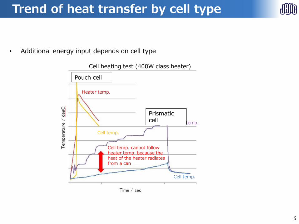
Cell heating test (400W class heater)
Trend of heat transfer by cell type
• Additional energy input depends on cell type
Pouch cell
dHeater temp.
Cell temp.
Heater temp.
Cell temp.
Prismatic cell
d
Cell temp. cannot follow heater temp. because the heat of the heater radiatesfrom a can
Trend of heat transfer by cell type
6
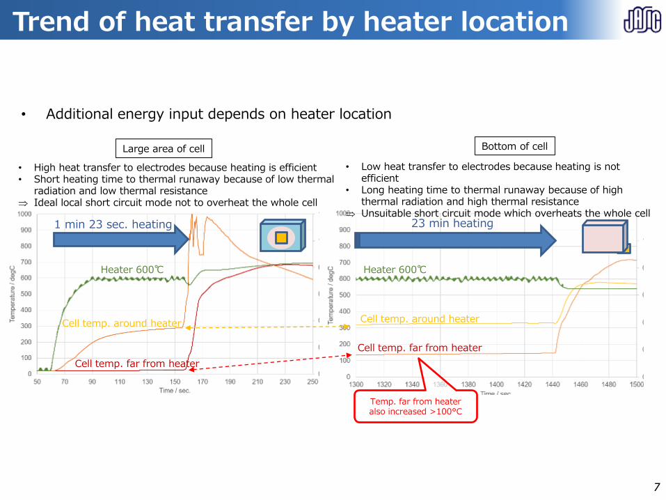
Heater 600℃Heater 600℃
Bottom of cellLarge area of cell
23 min heating1 min 23 sec. heating
• High heat transfer to electrodes because heating is efficient• Short heating time to thermal runaway because of low thermal
radiation and low thermal resistance Ideal local short circuit mode not to overheat the whole cell
• Additional energy input depends on heater location
Cell temp. around heater
Cell temp. far from heater
Temp. far from heater also increased >100°C
Trend of heat transfer by heater location
Cell temp. around heater
Cell temp. far from heater
• Low heat transfer to electrodes because heating is not efficient
• Long heating time to thermal runaway because of high thermal radiation and high thermal resistance
Unsuitable short circuit mode which overheats the whole cell
Trend of heat transfer by heater location
7
【Test result】 High-power heater
【Test result】 High-power heater
8
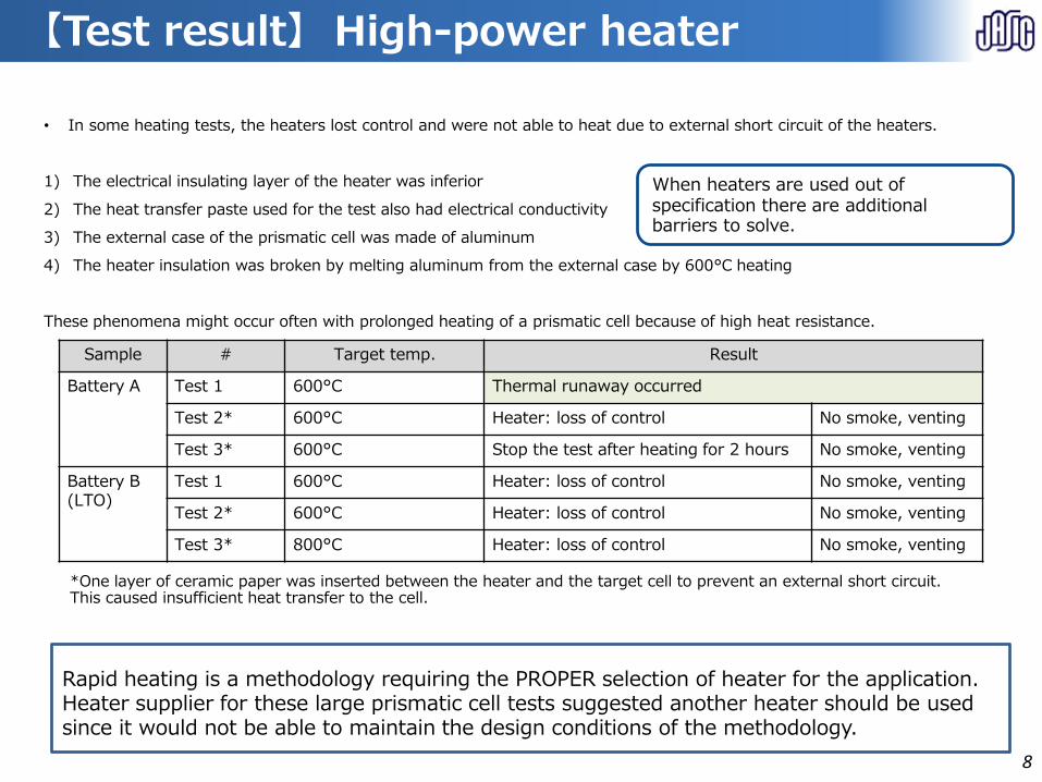
Sample # Target temp. Result
Battery A Test 1 600°C Thermal runaway occurred
Test 2* 600°C Heater: loss of control No smoke, venting
Test 3* 600°C Stop the test after heating for 2 hours No smoke, venting
Battery B(LTO)
Test 1 600°C Heater: loss of control No smoke, venting
Test 2* 600°C Heater: loss of control No smoke, venting
Test 3* 800°C Heater: loss of control No smoke, venting
• In some heating tests, the heaters lost control and were not able to heat due to external short circuit of the heaters.
1) The electrical insulating layer of the heater was inferior
2) The heat transfer paste used for the test also had electrical conductivity
3) The external case of the prismatic cell was made of aluminum
4) The heater insulation was broken by melting aluminum from the external case by 600°C heating
These phenomena might occur often with prolonged heating of a prismatic cell because of high heat resistance.
*One layer of ceramic paper was inserted between the heater and the target cell to prevent an external short circuit. This caused insufficient heat transfer to the cell.
Rapid heating is a methodology requiring the PROPER selection of heater for the application. Heater supplier for these large prismatic cell tests suggested another heater should be used since it would not be able to maintain the design conditions of the methodology.
When heaters are used out of specification there are additional barriers to solve.
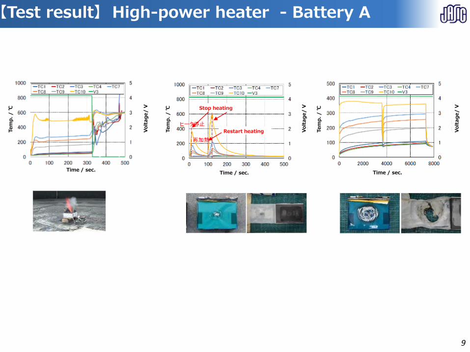
【Test result】 High-power heater - Battery A
Time / sec.Time / sec. Time / sec.
Tem
p.
/℃
Tem
p.
/℃
Tem
p.
/℃
Volt
ag
e/
V
Volt
ag
e/
V
Volt
ag
e/
V Stop heating
Restart heating
【Test result】 High-power heater - Battery A
9
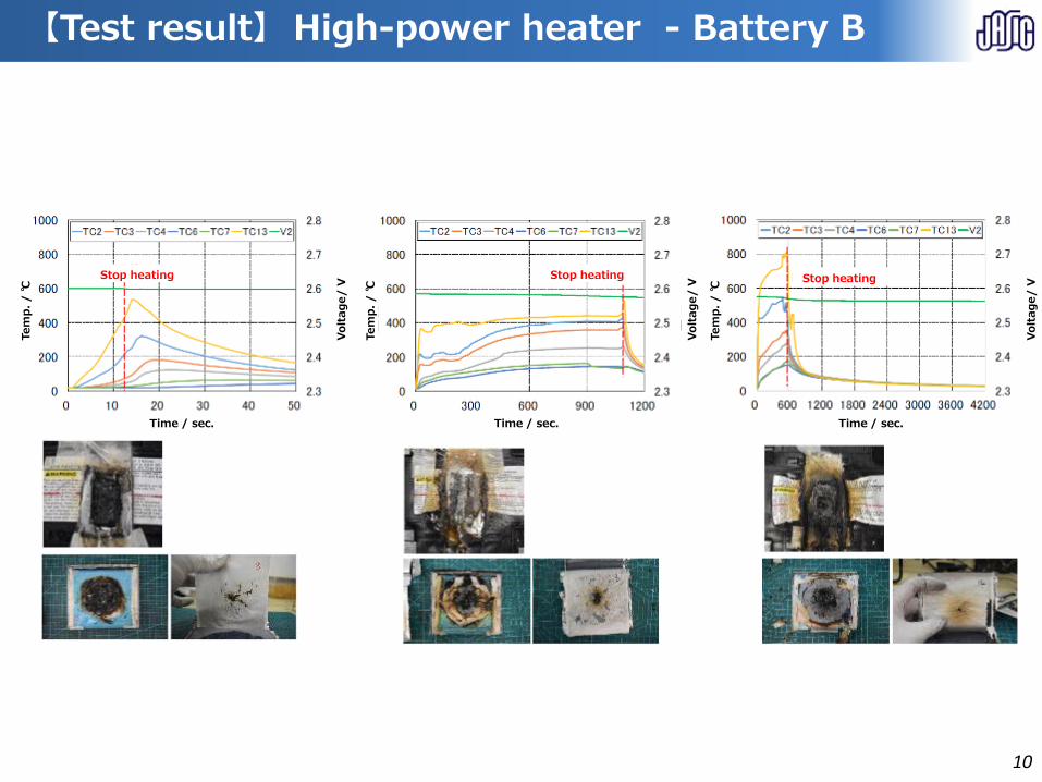
【Test result】 High-power heater - Battery B
Time / sec.
Tem
p.
/℃
Volt
ag
e/
V
Time / sec.
Tem
p.
/℃
Volt
ag
e/
V
Time / sec.
Tem
p.
/℃
Volt
ag
e/
V
Stop heating Stop heatingStop heating
【Test result】 High-power heater - Battery B
10
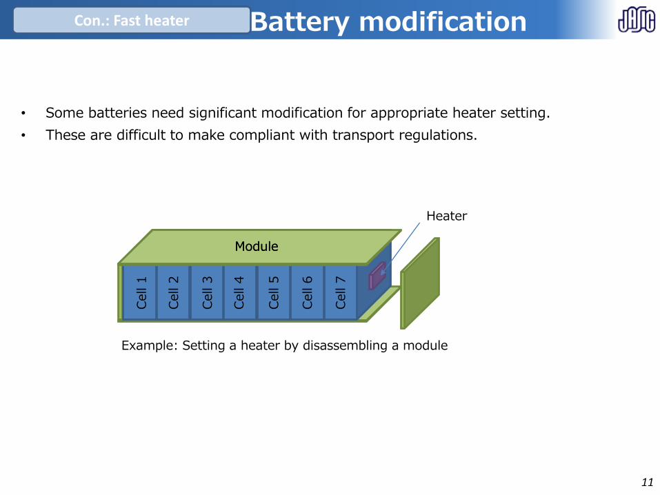
• Some batteries need significant modification for appropriate heater setting.
• These are difficult to make compliant with transport regulations.
Battery modification
Module
Cell
1
Cell
2
Cell
3
Cell
4
Cell 5
Cell
6
Cell
7
Module
Heater
Example: Setting a heater by disassembling a module
Con.: Fast heater Battery modification
11
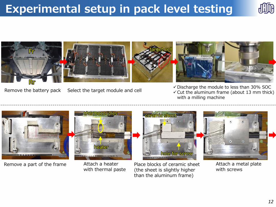
Experimental setup in pack level testing
Fr
Rr
target cell
Remove the battery pack Select the target module and cellDischarge the module to less than 30% SOCCut the aluminum frame (about 13 mm thick)
with a milling machine
Attach a heaterwith thermal paste
Remove a part of the frame
thermocouples
heater
Place blocks of ceramic sheet (the sheet is slightly higher than the aluminum frame)
hole for screw
ceramic sheet
Attach a metal platewith screws
Experimental setup in pack level testing
12
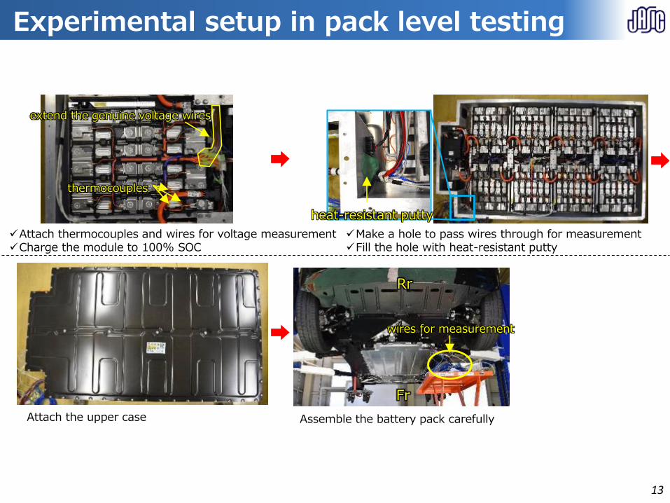
Experimental setup in pack level testing
Attach thermocouples and wires for voltage measurementCharge the module to 100% SOC
thermocouples
extend the genuine voltage wires
Make a hole to pass wires through for measurementFill the hole with heat-resistant putty
heat-resistant putty
Attach the upper case Assemble the battery pack carefully
Fr
Rr
wires for measurement
Experimental setup in pack level testing
13
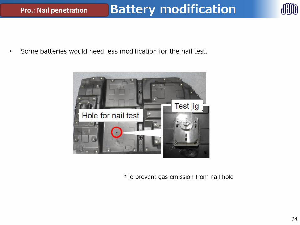
Pro.: Nail penetration
• Some batteries would need less modification for the nail test.
*To prevent gas emission from nail hole
*
Battery modification
Battery modification
14
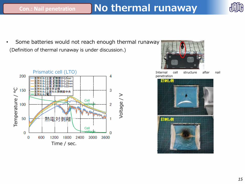
Prismatic cell (LTO)
• Some batteries would not reach enough thermal runaway
(Definition of thermal runaway is under discussion.)
Con.: Nail penetration
Internal cell structure after nailpenetration
Tem
pera
ture
/ °
C
Time / sec.
Voltage /
V
Cell voltage
Cell voltage
No thermal runaway
No thermal runaway
15
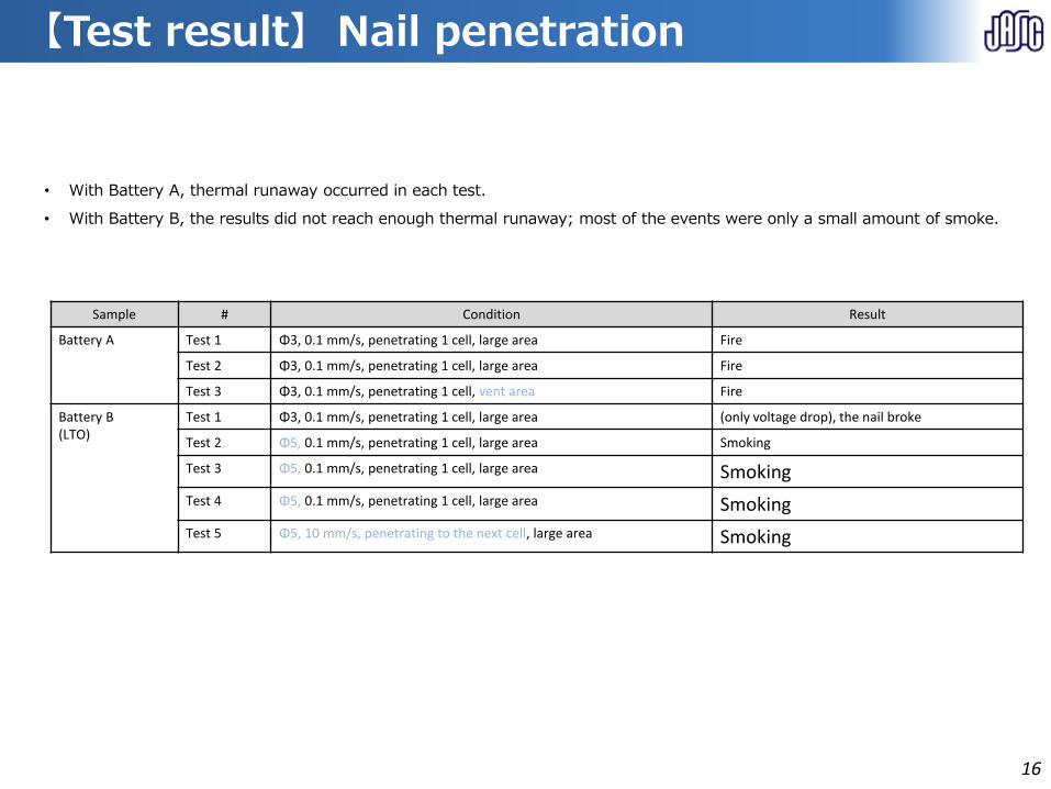
【Test result】 Nail penetration
Sample # Condition Result
Battery A Test 1 Φ3, 0.1 mm/s, penetrating 1 cell, large area Fire
Test 2 Φ3, 0.1 mm/s, penetrating 1 cell, large area Fire
Test 3 Φ3, 0.1 mm/s, penetrating 1 cell, vent area Fire
Battery B(LTO)
Test 1 Φ3, 0.1 mm/s, penetrating 1 cell, large area (only voltage drop), the nail broke
Test 2 Φ5, 0.1 mm/s, penetrating 1 cell, large area Smoking
Test 3 Φ5, 0.1 mm/s, penetrating 1 cell, large area Smoking
Test 4 Φ5, 0.1 mm/s, penetrating 1 cell, large area Smoking
Test 5 Φ5, 10 mm/s, penetrating to the next cell, large area Smoking
• With Battery A, thermal runaway occurred in each test.
• With Battery B, the results did not reach enough thermal runaway; most of the events were only a small amount of smoke.
【Test result】 Nail penetration
16
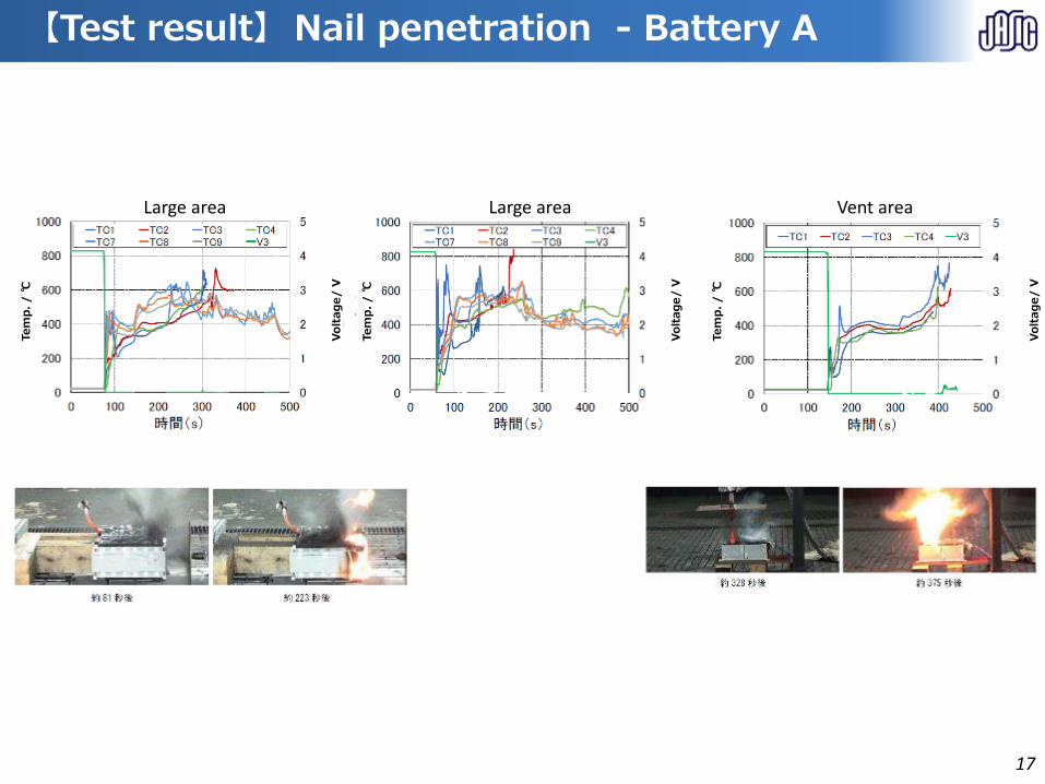
【Test result】 Nail penetration - Battery A
Tem
p.
/℃
Volt
ag
e/
V
Tem
p.
/℃
Volt
ag
e/
V
Tem
p.
/℃
Volt
ag
e/
V
Large area Large area Vent area
【Test result】 Nail penetration - Battery A
17

【Test result】 Nail penetration - Battery B
Tem
p.
/℃
Volt
ag
e/
V
Tem
p.
/℃
Volt
ag
e/
V
Tem
p.
/℃
Volt
ag
e/
V
#1: Φ3, 0.1 mm/s, penetrating 1 celllarge area
#2: Φ5, 0.1 mm/s, penetrating 1 celllarge area
#5: Φ5, 10 mm/s, penetrating to the next cell, large area
the nail broke
gas
gas
【Test result】 Nail penetration - Battery B
18
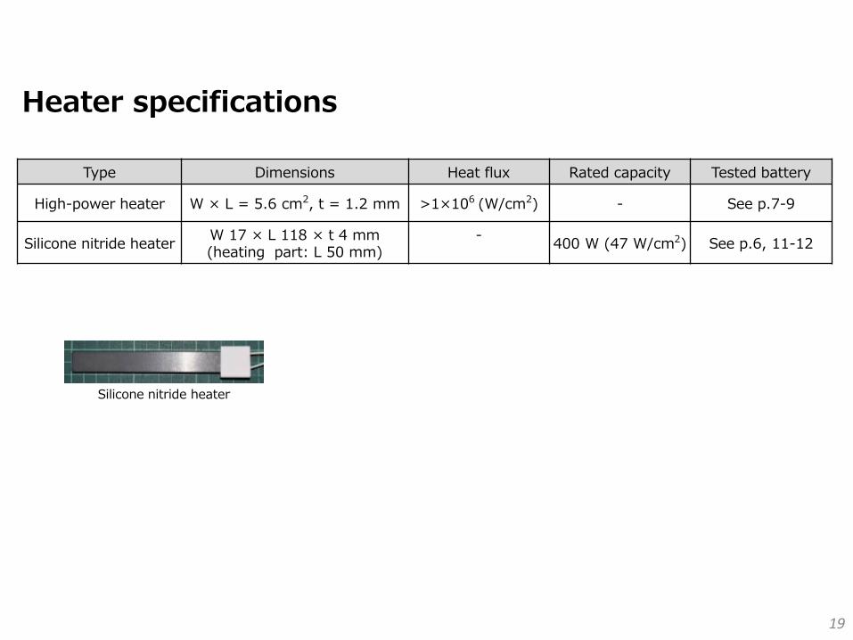
Heater specifications
Type Dimensions Heat flux Rated capacity Tested battery
High-power heater W × L = 5.6 cm2, t = 1.2 mm >1×10⁶ (W/cm2) - See p.7-9
Silicone nitride heaterW 17 × L 118 × t 4 mm(heating part: L 50 mm)
-400 W (47 W/cm2) See p.6, 11-12
Silicone nitride heater
19
1. Initiation Methods for Thermal Propagation
(Test Results)
2. Proposal on Test Procedure
20
Current Test Procedure and Challenging Issues under GTR-Phase1
test
Fig. 1 Visualized Test Flow on Thermal Propagation based on EVS-GTR-Phase 1
Any methods selected by OEM
Criteria
are
satisfied
Pass Fail
No
Yes
Pass
Thermal
runaway
occurs
21
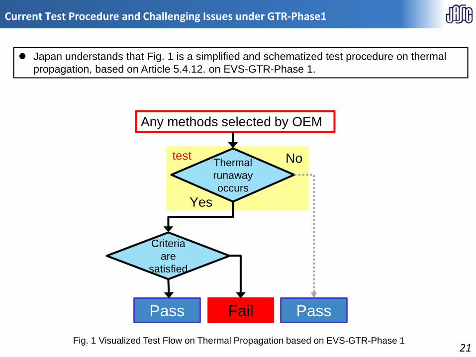
Japan understands that Fig. 1 is a simplified and schematized test procedure on thermal
propagation, based on Article 5.4.12. on EVS-GTR-Phase 1.
test
Fig. 1 Visualized Test Flow on Thermal Propagation
based on EVS-GTR-Phase 1
Any methods selected by OEM
Criteria
are
satisfied
Pass Fail
No
Yes
Pass
Thermal
runaway
occurs
22
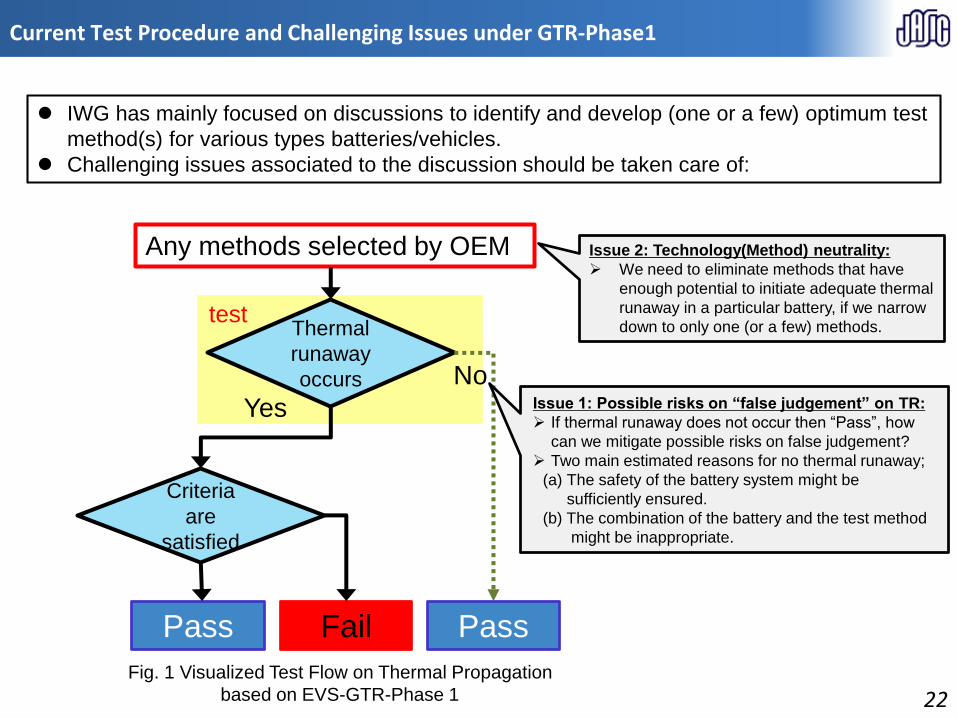
IWG has mainly focused on discussions to identify and develop (one or a few) optimum test
method(s) for various types batteries/vehicles.
Challenging issues associated to the discussion should be taken care of:
Issue 2: Technology(Method) neutrality:
We need to eliminate methods that have
enough potential to initiate adequate thermal
runaway in a particular battery, if we narrow
down to only one (or a few) methods.
Issue 1: Possible risks on “false judgement” on TR:
If thermal runaway does not occur then “Pass”, how
can we mitigate possible risks on false judgement?
Two main estimated reasons for no thermal runaway;
(a) The safety of the battery system might be
sufficiently ensured.
(b) The combination of the battery and the test method
might be inappropriate.
Current Test Procedure and Challenging Issues under GTR-Phase1
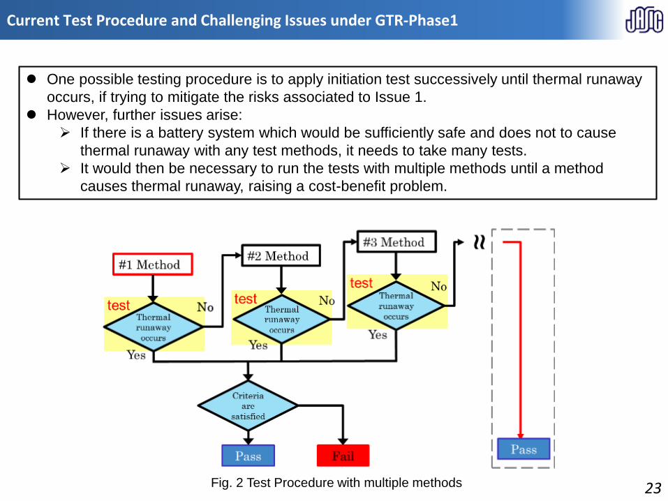
Fig. 2 Test Procedure with multiple methods 23
Current Test Procedure and Challenging Issues under GTR-Phase1
One possible testing procedure is to apply initiation test successively until thermal runaway
occurs, if trying to mitigate the risks associated to Issue 1.
However, further issues arise:
If there is a battery system which would be sufficiently safe and does not to cause
thermal runaway with any test methods, it needs to take many tests.
It would then be necessary to run the tests with multiple methods until a method
causes thermal runaway, raising a cost-benefit problem.

Fig. 3 Proposed Test Procedure
Proposal: Test Procedure
To solve these issues, Japan proposes the modified test procedure (see Fig. 3), dividing the
methods agreed upon by the IWG members into two categories (Main/Optional) and
changing the test flow accordingly.
The proposed test procedure would be expected to give answers to the raised challenges:
- Mitigating the possible risks on false judgement on thermal runaway
- Maintaining technical(method) neutrality by offering “Optional methods”
Any methods selected by OEM
24

Thank you for your kind attention!
25