j!iil ill j up*! - dtic.mil · department of the army project no. 503-03-001 ordnance research and...
TRANSCRIPT
i
•i
i!
.i
I
j i E C
[ ?
«e
i iij
llllliliiiiiiii
iaer till iJllN. wfl
ii if M • ill!
Illlll!
mn. ill
l! II ii!
«iai III- Hilt i •n:"':"i " ' i
!...!>" J!IIL ill
uiiiiLe..
m I i
'lEBSMSS'
II III I m i!
ii! I
if
UP"*! J REPORT No 898
Notes on a Theory of Spinning Shell
R. H. KENT
a.
DEPARTMENT OF THE ARMY PROJECT No. 503-03-001 ORDNANCE RESEARCH AND DEVELOPMENT PROJECT No. ^B3-0T08
BALLISTIC RESEARCH LABORATORIES *3SiSft6M*S ^-^iiiii^i'^^^i^; -•'• -^•' • sSgaaaisi f-., .» \---:±- iu,j.:_^-~i:*,*^...t^;;;.*;i.-:±_-.;-?>
ABERDEEN PROVING GROUND, MARYLAND

THIS REPORT HAS BEEN DELIMITED
AND CLEARED FOR PUBLIC RELEASE
UNDER DOD DIRECTIVE 5200,20 AND
NO RESTRICTIONS ARE IMPOSED UPON
ITS USE AND DISCLOSURE,
DISTRIBUTION STATEMENT A
APPROVED FOR PUBLIC RELEASE;
DISTRIBUTION UNLIMITED,

^KATA SHEET FOP nor rv„~ Jhtmn ***** S0- 898
^ ox Spinnilag Shell by
S. jf. jknt
«* * »* «. ^ ^ . ^
^ *' "««W footnote i„ n M ^"'ej in the en»^*-»« n>
— 3.: — e9Uation .^^ ^
-«-a xine from too . r~o "P - replace u by V-
b» "Initial distribution has been made of this report in accordance with the distribution list contained herein. Additional distribution with- out recourse to the Ordnance Office may be made to United States military organizations, and to such of their contractors as they certify to be cleared to receive this report and to need it in the furtherance of a military contract ••
REPORT SO. 898
February 195U
SOTS? OH A TfiEOKT OF SPIHSISG SHELL
R» E. Kent
Department of the Araiy Project So. 503-03-001 Ordnance Research and Develcpsnnt Project Ho* TB3-0108
ABERDEEN FROTHS GROUHD, MARYLAND

•R)
ti
Notes on a Theory of Spinning Shell
TABLE OF COHTEHTS
Abstract ............... ^ ..... .
Definition of Symbols .*..«.«.«••••••
Chapter I Motion with a Simplified Force System
Chapter II
Chapter III
Chapter IV
Chapter V
Equations of Motion with a Spinning Coordinate System. The Spins Caused hy t!se Cress Wind Force, the Magnus Force and Gravity. *
The Yawing Moment Due to Yawing, the Magnus isfcaent, the Equation for the Complex Yaw .....
Tis Solutions of the Equation for the Complex Yaw« Stability. . . . * * = , * '.
The Motion of the Coordinate System, Comparisons with Fowler, Gallop, Lock and Richmond, and with Kelley acid McShane. Neglected Forces. Acknowledgments .....
VI
11
17
21
27
iii

BALLISTIC RESEARCH LABORATORIES
REPORT NO. 898
RHKftnt/8281/iph Aberdeen Proving Ground, Md. 7 icuruBij Jk&j-'
HOTSS OH A THEORY OF SPIHHXHG SHELL
ABS'JSACT
The theory expounded here is based Baiuly on that of F&eier, Gallop, Lock and Richmond* except that the coordinate system is attached to the actual trajectory instead of the particle tra- jectory* They are followed i£> their fortunate choice of eyubols, especially for the damping factors.
£a& equations for the complex year are developed on the usual linear assumption and their solutions obtained* The dysssical stability of «b*01 i« dlacuaead* It is here pointed out that, for practical purposes, it is not essential that a shell be dynamically stable at all points of its trajectory. A reassuring comparison is made between the results of this theory and those of FGLR and Sellay and HcShaee.
I
"Phil. Tranc. Roy. SocD A, vol. 221, pp. 295-387 (1920).
I
DSFIKITIOS OF OTCMBCLS
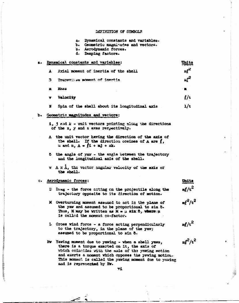
&• Dynamical constants and variables* b. Geometric magnitudes and vectors- s. Aerodynamic forces. d» Damping factors*
a* Dynamical constants and variables;
A .Axial moment of Inertia of the shell
3 Tn&ssrc:- »*» wowAgt o? l»*5+i«
m maae
v Velocity
N Spin of the shell about its longitudinal axis
b. Geometric magnitudes and vectors;
1, *, r4d k - unit vectors pointing aiosg the directions of the x, y and z axes respectively*
A the unit vector caving the direction of the axis of the shell* If the direction cosines of A are (, » and «, A » jfl + aj + ax*
o the angle of yaw - the angle between the trajectory and the longitudinal axis of the shell*
v A x A^ the vector aagulag velocity of the axis or the shell*
*feita
=*2
r/t i/t
c* Aerodynamic forces;
li ?>mm - the force acting on the projectile along the trajectory opposite to its direction of motion.
M Overturning moment assumed to act in the plane of the yav and assumed to be proportional to sin o. Thus, M may be written as M - u sin B, where p is cfcllFd the moment co-factor.
L Cross wind force - a force acting perpendicularly to the trajectory, in the plane of the yaw: assumed to be proportional to sin 8.
itv Tawing moment due to yawing - when a shell yaws, there is a torque exerted on It, the axis of which coincides witn the axis of ths yawing motion and exerts a sioment which opposes the yawing motion This momaut is called the yawing moment due to ys»ing and Is represented by Hw.
Units
»jf/t2
«*2A2
•f/t'
*J?2A2
•
Unite
*?/ 2 K Ma^iue force - corresponding to the cross v±ud mf/t
force, when a shell spins, there is a Magnus force acting on it, proportional to sin 8, but acting perpendicularly to the plane of the yav.
J Magnus moment - the moment of the Magnus force* rof /t
-2 / 2 -AHP Rolling moment - the moa&ent that opposes the znf /t
W£T*^» WA VAM» Cl l*J hi*
* d. Deuuplng factors ;
i The rolling moment damping factor
g AH * " All
K The cross wind force damping factor
L R m 1
mv sin o
h The yawing moment due to yaving damping factor
h - - H/B
X The Magnus fores damping factor
X K " mr N sin 6
7 The Magnus moment damping factor
-T 7 - AH sin 6
¥ These damping factors all hare l/t for unit*
all
*
Chapter I
Motion with Simplified Force System*
Tto simplify tits problem and to orlug out the essential pointB of the M theox-y, we shall consider first a shall subject to a force system con- -j slating only of the overturning moment, M, the drag, D, and a spin fentroy-
Ing couple or rolling moment. We take
w _ —fss * »•* — i> •»•*£! v
c where ji is the moment co-factor and 8 is the angle of yaw. We assume the A magnitude of the rolling moment to be AH p where A is the axial moment of N inertia of the shell and H the spin* The axis of the torque AN f" is that p of the shell.
Gravity#- the cross wind force, yawing assent due to yawing, etc., are
Since there are no forces transverse to the trajectory, the trajectory is linear* Therefore a coordinate system with origin at the center of
x gravity of the shell, with its x axis pointing along the trajectory, with y its y axis in a vertical plane, and the z a^is pointing to the right, while z not Galilean with respect to translation, is Galilean so far as angular
motions are concerned. See Figure 1. *
Figure 1
- The unit vectors having the directions of the x, y, z axes are designated , as i, J, k, respectiv^ly. (These vectors as well as all other vectors £ are written with heavy letters.) We define the relevant quantities.
B B = loomant of inertia about a transverse ex^B through the center of gravity.
A/. A - unit vector in the direction of the axis of the shell.
v w » the resultant vector angular velocity of the longitudinal axis about a transverse axis through the center of gravity (also called the cross spin).
H • total vector angular momentum of shell with respect to 0.
-
•:
I V
By re«son of the symmetry of revolution vtitch the shell is assumed to possess, the total angular racmantura is the sum of two components:
(a) the component about the axis, *?hieh has tfc* direction A and is represented by the vector ANA., and
(b) the component transverse to the axis, which is represented by the vector Bw.
Tom rector cross spin v is equal in magnitude to A and is perpendicular to A and A . V© thus have
w - A x A .
The total angular momentum,
I - AHA. + B |~A x A ( .
The vector equation of motion is that the rate of change of angular
0 momentum, H, is equal to the Impressed vector couple, designated by 0.
If we take N as variable we fixd that
• • • r*» • ~i •• i H - ANA + AHA + B A x A + B [A x A J «
• • • • The A x A term ia iero since A and A are parallel* Thus
(1) E = AHA + AHA. + B f A x A | = G .
On the present assumption, the vector couple 0 consists of two terms, the couple M and rolling scssnt AJJf"* . Let us »e« how we may express them as vectors.
** M is equal in magnitude to u sin & and the axis of the couple is obviously perpendicular to the trajectory and hence to the unit vector 1, and to the axis of the shell.
r• -i Consider the vector, \i x Aj ; this vector is, by definition of the
vector product, perpendicular to 1 and A and has the magnitude sin o.
Hence, the moment M is expressed as the vector, u ML s AJ • The rolling moment, AKT , hae by definition A as its axis and the moesnt Is assumed to be negative. Hence we represent it vectorlaliy as -AH p A*
Heplacing 8 in the preceding equation by its two components, uji x A and -AH PA, the equation becomes *— -*
(la) H = AHA + AHA + B \ A x A~| - u | i x A | -AHP A ; — 4 L_ j
this Is the vector equation of motion. -* Differentiation with respect to the time, t, is indicated by the superposed dot.
o 2 2
**In ballistic notation, •••Kv.P'1 y •
r9- ^

It should be noted that since A is a unit vector, A is necessarily per- pendicular to A, while [A x XJ and jjl x XI are perpendicular to A by the definition of a vectov product. Hence, if we take the scalar product of A into equation (l), all the terns vanish except AN(A*A) and -ANf (A«JJ.>. From this
AH « -A»T and
Alia - -AN r A.
By virtue of this, it is obvious that (la) may be written
(1.01) AKa + B LA x AJ - ji 11 1 x A I
If the direction cosines of A with respect to the x. y, z axes are jf, m. and n,
A » Ii + mj + nk
A = jf i + ng + nk *•
A • f4 •*• ag + nk
and
I A x A J - (jfl + mj + nk) x ( /i + aj + nk) .
Upon performing the vector multiplication, remembering that
i v 1 - 0, i x ,1 - k, Jii» -k, etc., we have
A x A « (an - am) i + («/ - /£) J + (jfif ^ a?)k .
For i x A, we have
i x (/i + nqf + nk) • - nj * ak *
Equation (i.O*) written out in full becomes
(1.01X) AN(jfi + aj + nk) + B j (an - n£)i + (nf - jfn)J +
+ (fa - ajf)k - u Q nj + aft | .
In this theory - the assumption is made that the yaw is small* If the yaw is email, then the i component, the magnitude of which is COP o, is always taken as unity, and therefore the i component is not involved in this theory*
Since the 13 J and k components are independent, there are three equations, one for each component* We take the 4 &£d k components:
(2) (j component) ASk + B (njf - jfa) » - un,
>{3) (k component) AJJn + B (jfa - ejf) » + urn .
i i

I
I is equal in magnitude to cos 8 « 1 » ~ and jf sy. = 8 -88.
Nov, m and n are of the order of 8* Hence, in neglecting rich, tents aa njf,
v? are neglecting a term of the order of (88 - 8~ ft) in comparison vitta 8
and in taking / • 1. we are neglecting a term of tbe order of 8 in compar-
ison with unity.. We nov take { » 1 and neglect the terns in ( .
Equations (2) and (3) then become
(2.1) AHm - Bn - - mi
(3*1) AHn + BE • * [is .
Multij'y (2.1) by i • -\-l and then aubtraet from (5*1) with the result,
A»(-im + n) + B(m + in) - u (m • in).
2 Since -(l) - -l(-l) » +1, the first term may be written -lAH(m + in)
and the equation becomes
CM -iAH(m + in) + B(m + in) - u (m -r in).
i) We now substitute r\ for (m + in) and call TJ the complex yaw.
The complex yaw TJ is represented on a plane perpendicular to the
trajectory as indicated in Figure 2.
&XJ s of /•«/$ m
T _j» 2
dX|S Of //>,»» 9//) »A/e-s
Figure 2
The axis of reals points upward in a vertical plane along the y axis
and the axis of lmaglnarles points tc the right along1 the z axis.
With i) substituted for m + in, (k) becomes, upon division by B
(**.!) rf-iaij-gii-O,
0 if 0 is used tc represent AN/B.
«5= ^
To solve this equa+ion, it is convenient first to eliminate the f| term. Let us write it for future convenience in the form
(k.2) if - IETJ - Ft) *= 0 . Ve nov make the substitution
il - y exp t ( i o
§1 { Edt
Upon differentiating once, ve have
t 1»7 «=? |i ( Edt 'dt <ex* |i J Edt
fl. f ...1 rr } y exp ^ x \ jsat j Edt j + y exp j = i } Edt (f i E)
• ax© 1 i»
i 1 f RHt. 2 1 — + £ i E y
Hie second differentiation give<?;
V- at {expj I1! Mt ! 1
(y -r ^ iEy) + eacp | i \ Edt o dt*y 2 '
exp
- exp
| i| Edt"j f| i E(y * | IBy) * ? • ^ • ^H .
ii^Edtj[y:+.(|lE + |iE)y+ (- \ E2 + f)yj .
Unon substituting for n, TJ, and TJ* in (U.2) it becomes
exp iijEdt f\
4 [? + iEy + (- \ E2 + ^)yj - iE(y + | iEy) - fy (
- exp 1
|i(Edt . ?+(% -F + |iE)y .0
and the equation for y is
U-3) y + ( Ec
P + | i E)y - o

Upon substituting for JS end F their values as obtained from (**-«l) and for the present taking il as constant, that is, neglecting E in (**-J}; we have
(k.k) ?+(£- - £)y - 0 . ^TT B
This may be written
y+^.2 fi.J
if
L 2
BQ — < x5/
il * - r i * * M L'-IJ
designating ill - l/s by a, we finally get
fi. c
(*.6>
y • vjs0/ y - o .
For convenience, following Kelley and Mc8hane , we rewrite (^«5) as
y - q*y * y + (lqj'y a 0
and make another substitution
d lo" y y r *
dt y
From this
<*.7)
and (^-6) becomes
2 2 ry + ry-qy»0, from which
2 2. r -»- r = q = 0 »
If r is small in comparison with r, we should have two solutions for r in this equation, one nearly equal to +q, and the other nearly equal to -q. Hence let
r = + q T £ •
By substituting JLu (V»7), it appears that
2 2 2 + q + £ + q • 2qc + €** - q •» 0,
from which, if v^ neglect k and € ,
t * - 2f* . and r • • q • wr • 2q ' -• • £q •Keiley-kcShaue, BRL Report 446, 19^7"" *»Kelley-McShans> refer to; H. Jeffreys, Proc. London Math. Soe. (2), vol. 23 (1923) p.428, aud G. Wentzel.. Zeitscbrift fur Physik. vol*38 (1926) p. 51S.

4
From the definition of r,
rdt • <?.(log y)
and t f rdt * loa y - log y , O °
t From this, log y • log y^ + \ rdt
o
and y-y0 e
J rdt C (+q - ^)dt
yQe
mus, the two solutions for +q and -q, respectively, are
r* > y - y, exp j \ \q - gMdt
2q' u
V • V <*YT»
* "2 "' < Ttous, y. and y2 are constants*
and
From (h,5) and \k,6) we have
+q - + —ir
-q lfio
Furthermore
2q = 210 o
Since A and B are const-ant,
2 <a • o> '
I
jr • = which we designate by - / ,
where jf is called the rolling moment damping factor* We have then,
7
substituting for q and q/2q, for **** two solutions
I f (10a + Jf - f) at y = yx exp
^"2 e*P L*I (~ iJto + ( - 2) at
fl $ "1 Recalling that r, • y exp ^ 1 j ftdt and that the general solution
(5)
is the sum of the two solutions, we have
Pl P2 TJ = i^ e + Kg e
where
and
io(i + c) + jf - 5
In (5)> K, and K^, are arbitrary complex constants determined by the
initial conditions.
Interpretation of Solution
For those who have nor, had experience in the field of complex quantities, an. interpretation of the solution (5) is offered.
v Consider the series expansion of e~.
1 + j -r *£ + et<% Upon substituting ix f or y in this, we have
_ix 2 5 h , . x ix^ x , ix
= i • ix - 2J- - -jj-+ 5T + 5i 5 6 —. •* t 7TV* "•* C • • • • sat
2 k 6 n X X X 1 ° 2T + 57 ~ 57 +,,° + i
x^ x5 x " 3T" 5T+ '•'
ix The first term on the expansion of e is the series for cos x while the
expression la the second bracket Is the series fcr sin x* Hence ve hsvc
ix e « cos x + 1 sin x .
For the case when u 1 x A is the only component of tba 1'orce systaa
and h » jf « 0 , the solution, as we have seen, Is of the form
iitt(l + o)t iiO(l - a)t TJ • K.e
h&z us write this as
(6) ,J^t + j^im*
(6.1)
and let us also assume for sltnplielty that K, and K^ are both reai..
Since a is the real part of r; and n the imaginary part of q, then in
ix view of the interpretation of e , (6) may be written as;
/m « K, cos axt +
{ n • K, sin (tt.t •
K2 cos os^t
K„ sin «a^t I- - -1 — V Consider an epicyclic motion of the following character. Let there be
a circle of radius JL. as ahoim in Figure 5 »"* let • point P move on it with
a constant angular velocity Ok* With P as a moving center, let there be
another circle of radius X- and a point, Q, moving on it with a constant
angular velocity a. •
-
Figure 3
9
:
!
2
If 6-'•* 0 is the axis of m's and 0 • */2 is the axis of n's, we have for m and n at any time t,
aeK, cos <xut + K_ cos COK*
n » K_ sin to, t + Kg sin Ogt .
But this is the same as given by (6.1) and the result establishes the cpicycllc cliwhwWr of tbe motion given in (6).
In cases of practical interest, neither a nor f is y.«ro? Let us
rewrite P. and P0 of (5) as
pi"11 fn (1 + ff>dt + i ) u '6/o) dt
P2 - 1 | f a (1 - o)dt + | ( (Jf - a/o) dt .
The first parts of P, and Vf are imaginary and the second parts are
real. In view of the fact that a is no longer taken as a constant, the
angular velocities m. and to- are no longer constant* The real second
parts indicate that the ssplitudcj ars no los^r either.
So, in place of (6.1), we write
n
{ fir ~I n f i> r, f "*! -.jKjCos j£}a(l+0)dt + Kgcos | I Q(i-o)dt j 't expl £ I (jf-&/o)dt
- jltjSin |Jo(l+o)at j -r KgSin | ( a(l-e)dt I exp | | f (MM** •
10
r» r»

Chapter II
Equations of Motion with a Spinning Coordinate System. The Spins Caused by the Cross Wind Force, the Magnus Force and Gravity*
The gp<»-«"',iwg Coordinate System
In the preceding, ve have follow, i the methods of Fowler, Gallop, Lock, and Richmond Is deriving equations (**.l) and (U.5) and the methods J>~-\ 1 ~_J V.. 1f.11.., ..—^ M^C'k«.~»5 4» A««J»4<i« •» V— a«l«*4<M> Vte *——*.* — _
the motion in the presence of a cross wind force, and other forces trans- verse to the trajectory, we depart from Fowler, Gallop, lock and Richmond, and adopt a coordinate system which is attached to the actual trajectory* Art In Chapter I, the unit vector, i, points along the trajectory, the unit vector, J, is initially in a vertical place through the trajectory, and the unit vector, k, is initially horizontal.*
As a result of the cross wind force and other forces having components transverse to the trajectory, our coordinate system will have a component of spin, a, about some axis transverse to the trajectory but no spin about the trajectory. By virtue of the spin, the coordinate system will not be a Galilean one. tfe proceed to derive first n and then Lhe equations of motion in this spinning non-Galilean coordinate system*
Consider a body of mass, m, moving with velocity, v, in the direction indicated by the unit vector, T. Its vector momentum is evidently mvr. The rate of change of momentum or the vector force is made up of two components, ravr and mvT. The first component, parallel to T, is the sum of the drag and the tangential corarponent of the force of gravity, while the Second cogspOiient is a force perpendicular to T. This 1B apparent since T is a unit vector and the only possible change in T is a change in direction. See Figure h.
1 Figure k
If we designate the vector force perpendicular to T by F , ve have
mv
The deviation of k from the horizontal direction and J from the vertical plane will be discusse^.lnJ Chapter.^ It will be shown that these deviations are small.
11

Thus, the angular velocity of the trajectory, a, is equsl in magnitude to
F n mv
As a vector, it.must be perpendicular to T and also T. Hence> the
spin of our coordinate system, IO»TXT»T!!— . v, n p
It is apparent that —- may b» replaced by —- , where P is the
resultant force on the shell, since the tangential eonmrment of ? sstess
no contribution to the vector product.
In the future, we shall replace T by 1 since by definition, 1 is the unit vector pointing along the trajectory* So that
(7) o.ixi»ix| . v" mv
Proa page 2, we have as the equation of motion
(1) am. + Aiwv + a (A x AJ- G .
K
The superscript • indicates time derivatives in a Galilean coordinate system. If superscript primes indicate time derivatives in our chosen
coordinate system, the Job i6 to express N. A and A in terms of N* . A' , A " oxiU CM.
As the first step, we state the following theorem:
|7»i) r0 - p„« + arx r.
»' u.
/
^X
p
Figure 5
In this, p' is the rate of change of the vector, r. as measured in
space 1 (non-Galilean) with axes x., y1, z.. Suppose this space is
spinning with respect to Galilean space, 2, with an angular velocity, CD,
as indicated. It is apparent that the velocity in space 2 of the point P at the end of r caused by the spin ©., will bs a x r. It may be
12
Jk**
i
•
rigorously shown that the rat* of change of r in space a, L , is to be
obtained by adding this term to r' • Hence, since space 2 is Galilean,
r2 » r* + o> x r, . ##
rYom this theorem, it follows directly that A * A' + o> x A and by a second application that
A" + a x A' + as' x A + CD x A' + CD x J~» x AJ » A*
A" + 2 a> x A* + a>' x A + » XtXA] Although © has no component about the trajectory, it does have a
component CD sin 5 about the axis of the shell, which makes an angle & irith the tangent to the trajectory- We shall neglect a> sin 6 in compar- ison with N. S6 we take the spin N unchanged in our coordinate system.
Upon making tha substitutions indicated above in (l), we obtain
AN'A + AWk* + AN» x A
/ r- x XI -ri (1.02) + B<A x A"+ [A x [«• x A]~| + 2|A X fix A*"] !
I III \
To simplify this result, we make use of a theorem of vector analysis,
[Xx [B x Cj I = B (A*C) - C (AfB) .
For the two triple and one quadruple products indicated by the superscripts I, II and III, respectively, we obtain
« »'(AtA) - ACA*®1) - «« - (A*eo»)A (I) I A x |o* x A"1
(II) 2|A x r® x A1"!"] « 2to (A'A') - 2A' (A'»)
(III) I A x [a> x Tco x AJ~|j - <B(A'|CD XA"|) - jco x A~j (A««)
In treating the term (A'OD'JA of I, we consider two cases* Ttie first case is the one where CD arises from aerodynamic forces and is therefore proportional to o. Since in the final A, we consider only the J and k components which are themselves proportional to 5, it is apparent that, *Ifce use of the superscript dot is appropriate since space 2 is Gallleau. ~ "The name Coriolis is associated with a similar transformation- See
"Classical )yibchaiiiesf,, pp. 136-157, by Goldstein.
13

for this case, (A*®:)A is at least of order 88° and may be neglected ia
this first order theory •> In the second case, m arises from gravity asi an and •* are always perpendicular to the particle trajectory; to the actual trajectory, they will he so nearly perpendicular th&£ ths product (A*®') will be of the order 8 and (A»®')A of the order of 8< This also is neglected.
1st II, since A is a unit vector, A' is necessarily perpendicular to A* Eence, the scalar product (A* A') = 0* The spin w is perpendicular to 1, hence, the product (A*») is at least of the order 8 and A' is of the order ft*. T^M» AYnrBsainti -2*,'f.A,2^ is at issjst of the order 55' snd is thus omitted in this small yaw theory.
±ii in, one »caa.ar product vA* i® x A i ) =» u, since j ® x A l is per- pendicular to A. *~ -1
In view of these considerations, (1*02) may be written
(1.03) AN'A + A8h° + AN fa x A~J
\ A x A** j + ®c - j® x Aj (A*®) f • G B
If the spin & is caused by aerodynamic forces, ® will be proportional to 8
PI 2 and the term I® x A j {A*®) will be at least of the order 8 and thus may be neglected.
W© proceed to ccapute tie spins, © , ca^, and ® caused by the cross
wind force, the Magnus force and gravity, respectively, thus obtaining the resuit»urtt anin m« m -f ®. -f ® •
i\ A g
The Cross Wind, Force #
rae cross wind force, L , is defined to be a force which acts per- pendicularly to the trajectory in the plane of the yaw. For this treat- •ssntfiaSs further assumed to be proportional to sin 8* So we take
L « A sin 8,
and call A the crosf. wind force co-factor. ;/ (A- Cosoi)
Consider now the vector difference
(A - cos 8 i); (see Figure 6). \—Cos €
Figure 6
*In ballistics, we write
L m X_ p d u ein 8. (See Hayes9 Elements of Ordnance-, p. kl2)>
Ik

It is obvious that (A - cos 5 l) huB the magnitude sin b and that it is perpendicular to the trajectory, the direction of which is i. Accordingly, a correct vector representation of the cross wind force is
>. (A - cos 5»i) .
Froiii (?) it appears that the spin © , of the coordinate system, caused by the cross wind force, is
f •»
4 * (A - coe 6 i) A i, _ . .. » n r\ L
mv
r- "i __
LlxAJ* s-krLlxAJ- •\ T
Upon replacing — or ", J by ic, we have for the spin GO caused * * ° mv mv sin ft * ' * K
by the cross wind force,
T "I oo^ = ft | i x A I »
Magnus Force
The Magnus force is a force which arises from the interaction of the boundary layer of a spinning shell and the wind stream when the shell has an angle of yaw. Consider a tennis ball or a baseball under the conditions shewn in Figurs 7» As a result of the interaction between the wind stream and the boundary layer, the velocity at the top surface of the ball will be
Direction of spin ^
wind velocity
Figure 7
less than the velocity on the bottom surface* of the bell. Associated with this will be a higher pressure over the top thu;a. thex*e is on the bottom producing a force which accelerates the ball in » downward direction. This is what happens when a tennis b&LL is given a top spin.
Consider a shell spinning as showu in Figure 8. As a result of the
A >- V^^—>- i
MofniS fe."ce
Figm
V
' 7
. Sj
spin of sh*//

pressure distribution mentioned, thers vill be a Magaus force> K, acting perpendicular to the plnae of the yaw, as indicated, which should be approximately proportional to the spin, K, the velocity of the shell, v, and to the sine of the angle of yaw, 8. If the factor of proportionality is represented by fm, we may write
K K - fmvN sin 6 (in magnitude)
and by
fmvN J A x i I as a vector.
X We shall represent fN in the above by X and call X** the Magnus for^e damping factor* The contribution to i caused by K is th»Y^»fore
mv ALT J
The spin QL caused by the Magnus force is
ilii ! - A j 1 X [A X f] I .
g The force of gravity is numerically equal to mg where g is the acceleration caused by gravity* This force has a component perpendicular
6 to the trajectory equal in magnitude to mg cos 0, where d in the inclina- tion of the trajectory to the horizontal. Therefore, in our coordinate system, the component perpendicular to the trajectory will be represented oy
- mg cos 9 J
It follows from (7) that the spin m . caused by gravity, will be g
ix (-6 cos 6 j) m e, k
M «t - n«g cos 6 since 6* « —=a .
The Resultant Spin of the Coordinate System
The spins caused by the cross wind force, the Magnus fores «ud gravity h&c rCopoCv«a.V£Ay ?
a> BicixA; ,
f8) < c^ • X i x (A x i] ,
a> m 0% k vIn ballistic notation, w* write, Magnus foree-K-K-^pd Nv sin &(in magnitude).
'"The damping factor X is to be distinguished from the crcsswind fore© co- i factor X.
W M M
In view of the small rotation of our system about the trajectory, the component of the gravity force will not be extictly represented by - mg cos 0$.
Shere will, in general, be a smell k ccsuponent.
I 16

Chapter III
Ths Yavlng Moment Due to Yawing. 'fhe Magnus Mossnt.
The Equation for the Complex Yaw*
We have so far considered the following elements of the force system:
Drag Overturning Couple Mel Cw"*l>lfi
Cross Wind Force Maguus Force Gravity
The last three forces contribute to the spin of the trajectory and, hence, to the spin of our coordinate system* In this chapter, ve consider the yavlng moment due to yawing and the Magnus moment, and derive the equation f >r the complex yaw.
Yawing moment due to yawing
# H The yawing moment due to yawing, designated by Hw , is the moment
which opposes the angular velocity of the axis of the shell*
h We define a yawing moment due to yawing damping factor, h, by writing
Hw • • h Bw •
As ve have seen in Chapter I (p<5«e 2), the angulsr velocity of the axis of
the shell w may be expressed as (A x A). Thus, if we are to take account of this moment, we include on the right hand of equation (1*03) on page lU,
- h B (A x A)
in addition to the overturning moment, u 11 x A I, and the axial couple, -AN PA. U
J
As has been mentioned, A is the angular velocity referred to Galilean axes, whereas, in this problem, we refer the motion to axes turning with the trajectory* We thus have to express A i« terms of A* and tb.v resultant angular velocity of the trajectory, <g» As we have seen in Chapter II, A is equal to A' + m x A. and thus
AxA-AxA' + A x [• x A j «
As we have also seen in Chapter II, the triple product A x j m x A i may be expressed as « - (« - A)A*- Hence — ~
"^.fe XAI- -hBllA XAG ie - (• • A>A } . •In ballistic notation, Br is expressed by , *
Kg p d vw
in which Kg is the yawing soment due to yawing coefficient and w is the
vector angular velocity of the axis of the shell. 17

The term (a * A)A will "be oailtted since it is of the order S in the 2 and k components. Thus we have, including the moments so far considered, for the right hand side of (l.Oj),
i H I i x A - AH pA - hB < IA x A' + oa >
Magnus Moment
On page 15, it appeared that the vector Magnus force is proportional to A x !• Ttoe masrmnt. of this force is perpendicular to the force aiw. %o the axis of the shell and is therefore properly given as proportional to
r~ —i A x | A x 1 I . We assume a proportionality f so tor cf AEy, wue» j is the
Magnus moraeirt damping factor, and write the Magnus moment,
J* » AN7 [A x IA x ±2 \ . 1— -H
This term is to be added to the right hand of equation (l>03) in addition to the ssossests ssatioasd above*
While it is commonly assumed in the small yaw theory that the Magnus force and moment are strictly proportional to the spin, there is little experimental evidence to back up this assumption. What evidence there is indicates that the force and moment are not exactly proportional to the spin. On the other hand, the evidence indicates that the Magnus force and moment are proportional to B for small yaws.
Including all the moments so far considered, the right hand side of (1.05) is
M r*:'xA"l - ^HA - hB j [A XA'1+ »/ + AHr JA X[A x ij | .
If the term - ANpA is cancelled against AN'A, (1*03), see psgs Ik, becomes «.
(1,04) AN(A* +| a> x A j) + B-f |A x A" j4 «s - (A * aft) JJD x A J f -
- ti Ti x A*1- hB T |A x A' "J + at + AH? A x [7. x il |
with the spin; mf as given in equation (7) of Chapter II by
a> « itfi x A~|+ A i xTk x ll + 8* k .
We are to expand (1*0V) in terms cf the j ac£ k components, the compon- ents of the complex yaw, and omit ths= i ccs^onents, if any, since in this small yaw theory, / - 1.
*ixx ballistic notation, we write J * Kjp d fi v sin 6 (in aagaitsdcO. I
i. 18

Before carrying out this expansion, it is convenient tc espsnd the vectors and the vector products i*a (l.o4),«
For mf on carrying out the indicated vector multiplications, ws find with ,
A • jf i + fflj + nk,
st = (=«n -r >«}J + (wa + Xn + 0*)* •
If the J and k conpoaants of the vectors and vector products in (1.04) are Indicated by the notation ( ). ». we have
(A*)« fc - m: j + nsk
if > —
(txA). V • (wa + to + 9')J + (an - ?s)k .
With the usual approximations.
fA x A'4 . _ • -n»» 1 + a" k J, k -••-•--
(•*)« V "" v-*0' + to1)* + (wa1 + to' + 8t5)k •
In treating the term (a * A) |«p x A | we need to include in m only the term $'•»; since • will \m proportional to 5 for the other components and the
2 tern itself will be of the order o for thees components»<.; ..
With « - e'k, S
On the right hand side of (1.04).
nk , ([*»AJ)I. *-••»•
(A "i A x i ! I , . » a * -!• nk *
Using thes« expression* for the vectors and vector products in (i.Cw),
AM dividing both ftidas by B, expressing the quotient -«• by Sif «nd collecting the terms is •• and k# respectively, we obtain
&0&* +iem + >?:. + 3') - n" + (-im' + Tan') - n0' « - £ n + hn* + hien - htan-QTK* o
) oCn'+icn m >ju)+ mM • («m* + >ai* * 69) » ^ « - hm'-hitm - Wm - h©' + Oyn .
••-• •••-,•, :•- ••:«-.-. .-,•*?•,.•,*. .v•- ^

We multiply the first of these equations by -i » -*f-l sod add to the second with the result:
fi Q im» + n' - K (iin - n) + X(-m - in) - i ej
•r ni" + in" -.• s(m' + in0) - *(im' - n°) + in0°2 + 9M =
- | (m + in) - h(in' + in0)- hn(m + in) + h ~h(iM - n) - ha" - fty{im - n) .
Replacing (m + in) by TJ, the complex yaw, as in Chapter I, and arranging "Cue t-rzjnwa. we xmve
TJro + KTJ° - lto/ ' lOll? - liters
-IIXTI - I n + hn8 + hi^ - ihAt) + ifiyn - 100° - 000 - in8°2 - hS°
or
(l.j06) Ti00 - i(fl + iK + ih + *)TJ° - I + Mic + AX - ifl7 - hn + ibA ji
- IQO° s!" in e°2 - he'
in p. **£ + i (e-^'H;
20
Chapter IV
The Solutions of tire Equation for the Complex Yaw, Stability*
In this chapter, we derive the solutions of the equation for the complex yaw (l«06). We first consider a particular solution cf the equation* We insert the particular solution in the equation and subtract the resulting equation from vl»06)« By so doing, vs get as huwogsseous equation*
The Particular Solution
We proceed with the derivation of the particular solution and shall consider later the solutions Of the homogeneous equation.
Following Keiiey and McShane, let us write (l*0o) in the form
(li07) TJ" + atj* -r hr, - c .
Assume a solution of the form
n - f + « , on the assumption that the i\n and n' terms are relatively small* On Inserting the solution in (1*07) sad rssglectieg r?" and e'. one finds
a / c *
and
(9)
In terms of the notation of equatloa (1*06) this gives
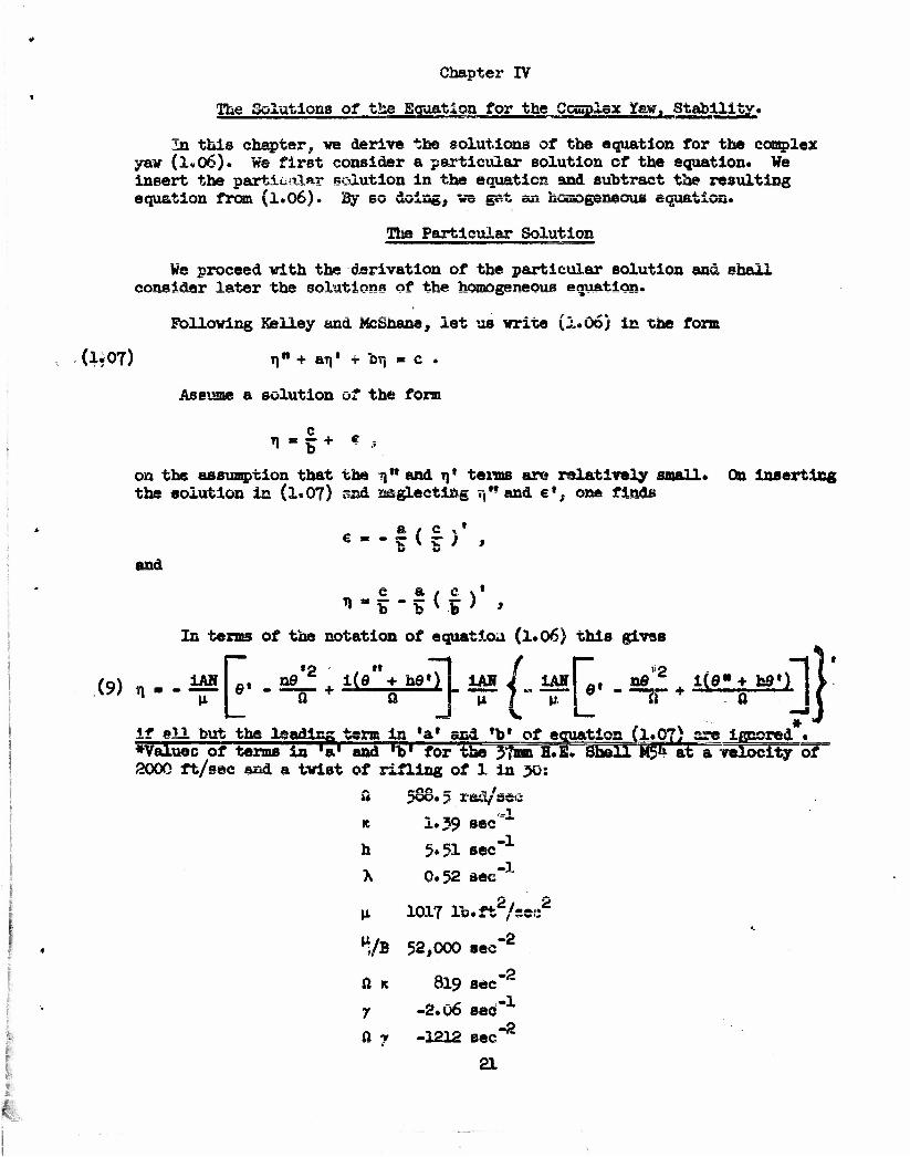
iAN fll ne'2 iCe" + hd1) IAN J IAHI -, nfi'2 i(g* + hg«) I
If eH but the leading term la 'a* and 'p' of equation (l.p^) are ignored * •Valuec of terms In 'a' and ,b' for the 37mm H.E. Shell M5& al" a velocity o 2000 ft/sec and a twist of rifling of 1 in 50:
»
of"
ft 5Q°o rad/se<3 R I.39 sec "*"
h 5.51 sec"1
X 0*52 aec"J
u 1017 lb.ft2/see2
tys 52,000 sec"2
ft ic 819 sec"2
7 -2.06 sec" ft 7 -1212 sec"2
21
•
12 ' * ' If n© , 5 . and h<9 in the first bracket, on the right are neglected
and the second term, is neglected entirely. (9) •becomes
(9*D u ~ v
In visv of the fact that the z axis is the axis or imaginarles, ($•!) indicates, on this approximation, that (a) the projectile is pointing directly to the right, and (b) the magnitude of the yav is given by
m4m fc AH g cos 6 (I V
The preceding is therefore a derivation of the result given In Hayes,, Chapter X, p. <tex>. Essentially, this expression for what is called the "yav of repose" vas used by Fowler, Gallop, Lock and Richmond in predicting the "right drift" of a projectile Kith a satisfactory sgrss&eul with experi- ment.
Solutions for the Homogeneous Equation
As vas pointed out, if we subtract the special solution (9) from (1*06), we get the follmring hessogeneous equation,
(10) TJ" - i(ft + isc -v ih + 70V - j^/B + ifl(t* - y - iX) - hK + ihXJr, = 0 .
As in Chapter I, we write (10) in the form
ij" - lEn' - Fn = 0
and make the transformation
ti«yexj?||i\Edt
obtaining "••* —
y«+ ( » - F + |i s')y - o .
Upon inserting the values of E and F from (10), this becomes
Sp - | + | (~iK + ih + 2iy - X) + | hK +
| i(idv + hK) - | (K2 + h2 - *2) + y" +
| i(fl« + IK' + ih1 + A')
If we neglect the products and squares of the damping factors and also their derivatives and write
fl« $o.-Xo.
§
I
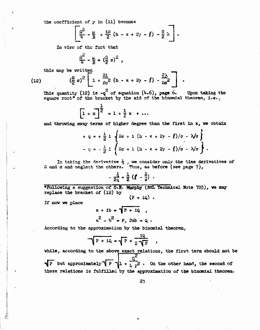
the coefficient of y in (ll) becoaes
i. - g + S (b - « • 27 - t) - I * • In visv of the fact that
this may he written ._
(12) (§ of |jL + ^2 (h - R + 27 - 0 - ^2 J .
This quantity (12) is -q of equation (U.6), page 6* Upon taking the square root* of the bracket by the aid of the binomial theorem, i.e.,
= 1 + ?r x + ••*
and throwing away terms of higher degree than the first in x, we obtain
+ q« + |iJfto + i(a-K + 27- I)/a - V* )
- q « - I i |0c + i(h-ie + 27- ()/o - V* J •
In taking the derivative q . we consider only the time derivatives of ft and a and neglect the others. Thue, as before (see page 7),
. _a c * it. i) . 2q 2 s* 0'
•Following a suggestion of O.K. Murphy (BHL Technical Rote 705), we may replace the bracket of (12) by
\r + mt . If now we place
a + ib - "|jp + iQ ,
a2 - b2 « P, 2ab » Q .
According to the approximation by the binomial theorem,
while, according to the above exact relations, the first term should not be
^P but approximately~yP "Ml + . 2 . On the other hand, the second of
these relations is fulfilled by the approximation of the binomial theorem.
23

Hence, the solution for y is
tf (13) y = yx ex? I i fjfio - I • ip!h . < + 27 - ft/o - ( + fj j dt
iiHO(T--+i(h«x J( • L
where y. and y? are complex constants.
y_ exD1 -* - j ^
')
If ve write this as
yA 4- "V flft 1 "fg**
then, in view of the fact that
il « y exp
E m (n + iK + ih + X), and that
we have for n.
I i I E dt o
(1*) t) * K. exp 1 ,* "1 I i J (n + ih ^ i* + X) dt + ^ j +
Kg exp I i f (0 + ih + ±K + X) dt + %
where K. and iC are complex constants.
Finally we write
(U.l)
U
P P 1 -_- _ 2 4 i^e n - I^e
From (14) and (lU.l), it is seen that
(15) P, = 5 f «/ i jn(l + a) + X - X/'ffJ - I h
t,' - I / j i I 0(1 - o) + X + X/o - h
+ K
+ K
-17 jf -r a/a + (h - K + 27 -jf)/cr |>dt,
II -ft ( + ^ - (h - K + 27 - /)/0 *? dt. *IJ
Since the s+.Ability factor is assumed to be appreciably greater than 1, the terse in X are negligible compared to those in ft*. Hereafter, X will be *E.g*, for the 20mm Practice Projectile T114 fired at a muzzle velocity of 3026 ft/sec with a twist of rifling of one turn in 25»4 calibers,
fl m 1525 rad/sec;
X • 0-2 sec" (approximately).
f f
I
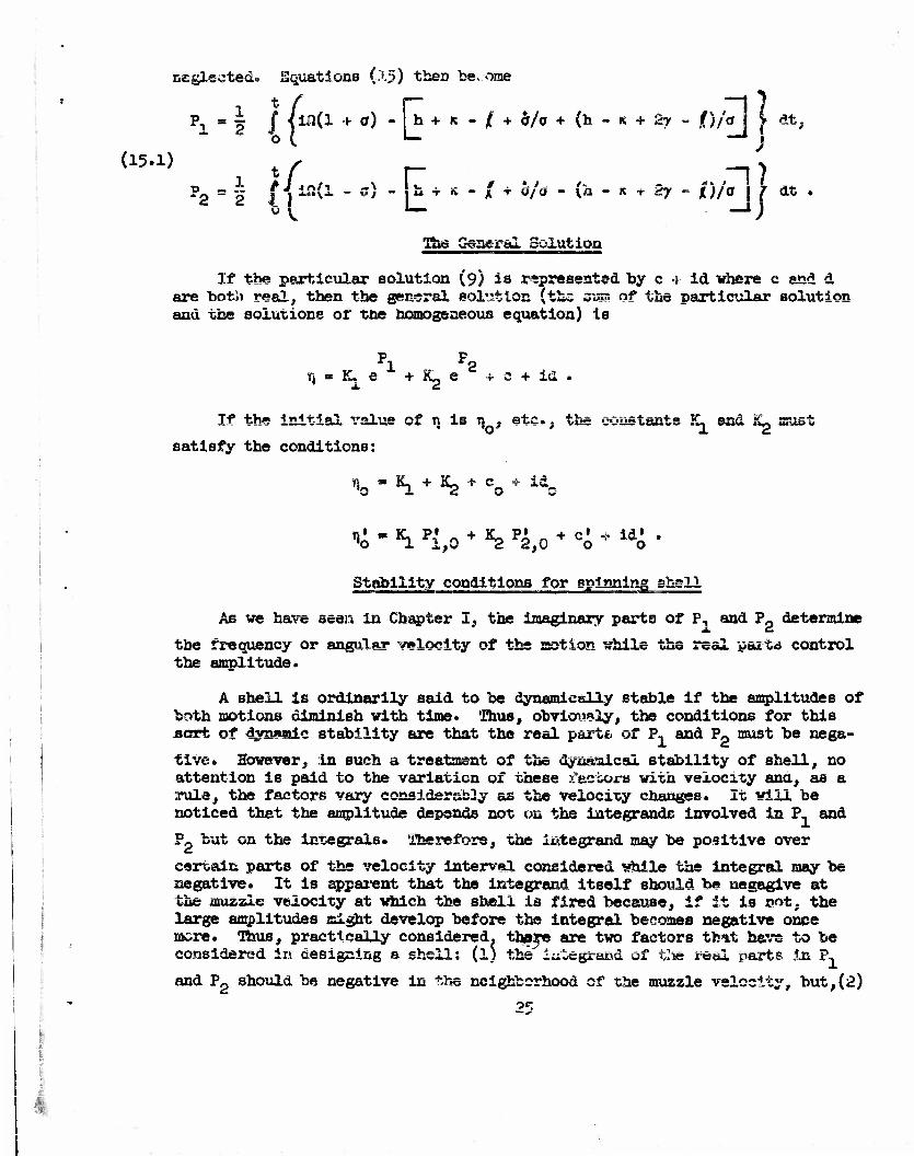
• .ft I -' I i
(15.1)
P., = § ]" /m(l + <r) - |h + K - /; + or/a + (h - »c + 2y - /)/a] [ dt,
The General Solution
If the particular 8olution (9) is represented by c -r id where c and d are "hot'a real, then the general solution (the StS? of the particular solution and tee solutions or toe Homogeneous equation) Is
Pl F2 rt » K, e +Le + c + id .
It the initial value of r, is n . ate.. the constants K, snd KL must
satisfy the conditions:
n»JL+K2+c_ + id. o
1 - «1 Pi,0 + *2 %0 + Co * id,
Stability conditions for spinning shell 11 111 1 '•• • 11 1 • • HI T 1 1 I>I 1
As we have seen in Chapter I, the imaginary parts of P. and P determine
tbe frequency or angular velocity of the motion while the real pasta control the amplitude.
A shell is ordinarily said to be dynamically stable if the amplitudes of both motions diminish with time* Thus, obviously, the conditions for this sort of dyrmmic stability are that the real part*, of P, and Pp must be nega-
tive. Hovever. in such a treatment of the dynamical stability of shell, no attention is paid to the variation of these factors with velocity ana, as a •.rule, the factors vary considerably as the velocity changes. It viii be noticed that the amplitude depends not on the integrands involved in P, and
Pp but on the integrals. Therefore, the integrand may be positive over
certain parts of the velocity interval considered vhile the integral may be negative. It is apparent that the integrand itself should be nagagive at the muzzle velocity at which the shell is fired because, if it is pot. the large amplitudes might develop before the integral becomes negative once more. Thus, practically considered, there are two factors tb*t have to be considered in designing a shell: (l) the iiitegrat\d of the real parts in P1
and Pg should be negative in the neighborhood of the muzzle velocity, but,(2)
en the other nand, if the integrands are reasonably negative in the neighbor- hood of the muzzle velocity, it is not essential that they he negative at all other velocities which the shell assumes on its trajectory* It is known that there are quite a number of shell which, in the narrow sense of the word, are dynamically unstable on certain pax to of their trajectories hut nevertheless are exceedingly accurate. It would be throwing away many perfectly good shell designs if one insisted that the integrand be negative at- all ve- locities which the shell takes on during its trajectory*
If c is real, the four conditions for the satisfactory lamping of the yaw of a shell on a given trajectory are:
near the muzzle
(a) Ih + R - i + b/a + (h - R + 27 - I) fa |^ 0
(b) |h + K - f + b/a - (h - K + 27 - O/o J. 0
along the trajectory
(c) f \ h + R - I + b/a + (h - K + 27 - ()/a |
"° I- -4
(*) /[* +
dt
(dynamically stable)
K - I + a/a - (h - R + 27 - jf)/i a }dt 1
0 ,
(not necessarily dynamioally stable at all points on the trajectory)
when t is any tlaae along the trajectory .
Ae Murphy suggests in BRL Report 853, for practical purposes, the 0*8 on the right of ihe above inequalities might well be replaced by positive constants*
As S'ier^e and Poor have pointed out, it may be dangerous to design ». weapon ior which all four stability conditions are satisfied only i/hen the shell it» fired for a certain muzzle velocity. If the muzzle velocity were inadvertently changed, the conditions no longer be satisfied.
'a' and 'b* might
?6

Chapter V
The Motion of the Coordinate System. Comparison with Fowler, Gallop, Lock and Richmond.
Comparison with Kelley and McShane. Neglected Forces. Acknowledgments.
The Motion of the Coordinate System
As compared with the coordinate system or Fouler, Gallop, Lock and Richmond, which is attached to the particle trajectory, oars has the advantage that it deals with only one vector. A. Instead of two, A and X (see below). As compared with that of Keliey and MsShane*,, it has the advantage of resembling more closely a Galilean system than one whose coordinates oscillate with the projectile. Howe-rex-, our coordinate system has the disadvantage that the z axis, originally assessed to be horizontal, will not, in general, remain horizontal, and the y axis, originally in a vertical plane: through the trajectory, will not, in general, remain in that plane. However, it will be shown tnat the departure of the z axis from the horizontal will bo small and the departure of the y axis from the vertical plane will be also.
Consider a projectile moving vertically upv&rd* Let us taite the y axis initially as coming out of the plane
x
Figure 9
of Figure 9 end the z axis as pointing to the right. Suppose there is a spin a> of the coordinate system about the y axis, then the z axis will
turn toward the vertical with the same angular velocity a> • Place a vertical
plane so that it will include the z axis and let • be the angle, measured in that plane between a horizontal line and the z axis* In this case, • = <D •
Let us consider the "eneral case* SiT**,,*ose the tsnssnt to the tr°Sector"" makes an angle d with the horizontal, let the z axis point initially directly to the right and let the y axis be initially in the vertical plane thru the x axis. See Figure 10.
Keliey and McShane have adopted the coordinate system of Nielsen and Synge. Cf. "On the Motion of a Spinning Shell7 Quarterly of Applied Mathematics, Vol. IV, No. 3, October 19**6, pp. 201-226.
27

:
#-Z
Kiciiro 10
It appears that the component of a> about an horizontal normal to the y
initial direction of the z tali* will h« m «in S-. So, in general, y
• = a sin f) .
It is atmarsnt that a rotation g> about the z axis, if z is horizontal,
will not mcr?e the y axis f xaa. the vortical.
On the other hand, if the % axis is not horizontal, a rotation about it, A . viii cause the y axis to leave the vertical plane through the trajectory.
However, <t> is approximately proportional too ss long as 4> in email'. Thus,
the departure of the y axis from the vertical will be approximately proportional to the product CD *» and will be neglected,
y z °^
It is obvious that a rotation about; the y axis will not change the direction of the y axis*
It thus appears that the rate of departure of the z axis from the hori- zontal is given by * = © sin 5, and that ths rate of departure of the y axis
will be cf higher order in the spins of the trajectory;
The spin of the coordinate system caused by gravity, <o , has no component
in cp1 . The main component of a> is that caused by the cross wind force, in
magnitude, - KT|.
With an assumed value of R « 1.0, Hitchcock and Harrington have computed
U) i U dt _ far dt *!** *f 9 Bta 8 ' Bin 6
for two cases, one where the motion is undamped (with damping due to K neg- lected) and one where the motion is damped with h • 3.2 and K * 1.0* This was for a 3.3" shell with a velocity of 208o ft/sec. The results were that, at the end of .6 see*, the maximum value of » for the undamped case
sin 6 was less thai* .003 ?&&> &&& less than .002 rad for the damped case.
2b

Co»?r^rl3oa with ^=^^Lta of FSLR >
Fowler and associates refer the motion to a coordinate system attached to the particle trajectory with only drag and gravity acting on the particle. In this system, they consider two vectors. One which we shall call A- is
the unit vector having the direction of the axis of the shell; the other. x, s, unit vector having the direction of the actual trajectory, both referred to the coordinate system mentioned.
Fowler writes
^ « VF + VF + VF
X » x£_, + yj._, + *k_ . (x,y,z are direction cosines.)
If we define the vector yew indicated by Za as the component of the vector A- normal to the actual trajectory, then with the coordinate system
of FGLR,
A, - Ay - X = (m_ - y)jp + (np - z)}^
since Jt <3g x #B 1 *
[ On the other hand, the vector representation of our complex yaw is
(mj + nk). Hence, if the small angles between our and their coordinate axes may be disregarded, i.e., if J_ • j, kp » itj.-ffi == su «• y, n « n„ - z .
S FGLR introduce two complex variables in their treatment, r\ and £ • The
definitions of these variables are es follows:
T) + c £ * 12^ + inj, , c g m y + is
where c • cos 0.
From these, it is seen that
H - (aij, - y) + ifrij, - z) ,
i and Fowler's r, is equivalent to our TJ, except for the slight difference between our axes and his.
On page 337, FGLR give, with slight changes in notation, the following equations involving TJ and £ .
(3*613) T)» -(ift-h-ic+i>v)Ti»-<(|^ +ift(ic«i7v-7)->i!e+-ShX-icf + IV -(K»1?0 ^ f n
- jj.Qc» - he* - cr I £ - Id m m{e< + 19&Q) .
* Where Q is the inclination of tba particle-trejectory«
29 :. I
•
This is to be compered with cur equation (1«06) on page 20. The differences are as follows;
a* FGLR have two terms in r,r -(*' - 1?\')TI and + (* - iX) •— »J
I i].
b, Hwy have a £ term which they later discard as being of the i
c. On the right haad side, we have two terms in the bracket of (1.06)
P ner~ „ ih0»
which Fowler considers negligible,
FGLR give as the solution (p. 339) for the simplified homogeneous equation in r\. with a alight change of form,
(3.623*) 1- (r?" j "ie + Vs
, t / -- —, ^
1 2 2 o ( " L - _j; and K. and K_ are arbitrary constants*
It way be shown that
fa*)"1—L}f«-*- • -*
I
In view of this, (3.623k) may be written
pi pp r\ « KjB x + Kge *
with the P's now defined by
P 'l' P2 = I J YLfl<1 ± •) "p +K-Jt + |t (fe-K + 27~ /)/©! t dt .
This is to be compared with (15.1) on page 25. It will be seen that the results are identical:
Another cossaant on Fowler's treatment: he claims his result to be valid oaiy for large values of Sj our results indicate that his results are of greater generality than he realized. In fact, they merely depend
1 I 1 30
on the u'sxisl W.K.B. approximations (see p. o) .
!
Comparison vith Kelley-McShane
Kelley-McShane use the arc length as the independent variable, instead of the time. Dr. Galbraith has kindly transicrr^d Kelley-McShane - s equation (1.25). BRL Report KUb; to its equivalent with time as the independent variable- The result, with our notation .tor the damping factors, is:
n - in(ft + lie + ih + -K + * ) - T) ("l + IO(K - 7 - IX) - i a&±^ e I
- ia e» (i + | + ^) . e».
*ln view of the fact that FGLR made their observations by~yawcards/they give, in addition to an expression for r^ths complex yaw, expressions for 62 and for •, the ecagle between a vertical plane through the trajectory and the plane of the yaw:
5 • a sin qt + p cos" qt .
1 f 1 • ••_+* Ot + arctan «* coth (.1 - a,) tan ot V .
O c L 3 " j In these,
a • maximum yaw
3 = minimum yaw
q * £ far
a - Je cosh (qp - j)
p * Je " sinh (r^ - j)
tanh J = 0 /a o o
J - ao/cosh j = 0o/sinh j
o
qg = , 2ff •——••— -v o
J 2c dt
51

If ttis is compared with (l?06) os page 20; it is apparent that, aside from the terms in $ which we xieglect, the only difference is the tens
±2& 5aS S ia the coefficient of t). In view of the fact that this term is u
omitted in ^Exterior Ballistics", by MeShejse,. aXeiley and Reno, it is apparent that Kelley and McShs.se consider it should he omJ, ti«d.
Neglected Forces
We have so far neglected three elsaente of the fores system because, in practice, the corresponding dealing f asters are negligible* These are:
,.\12 »KTCC N*"U^ i/C yikVjkug,
the Magnus force due to yawing,
the Magnus moment due to yawing.
force due fco yawing,
The yawing moment due to yawirg is produced by she product of a force multiplied into the distance between the center of application of the ?orc? e»* ths center of gravity. This force is the force due to yawing* It is important in the motion oi dirigibles and of interest in developing a tneory of the yawing moment due to yawing. It has a negligible effect on the motion of ordinary shell.
b- The Magnus force due to yawing
Just as there is a Magnus force which corresponds to the cross wind force, so there is also a M&guus force du« to y&wisg. As a result of thus spin of a shell, the Magnus force due to yawing differs in magnitude and direction from the force due to yawing* This force is also negligibly small and need not be considered in the theory of damping*
c. The Magnus moment due to yawing
Corresponding to the yawing moment due to yawing, if the shell is spun, there will be a Magnus moment due to yawing but this Magnus moment is also negligibly small*
3?

Acknowledgments
I have received much helpful advice tind many useful suggestions in the preparation of these notes; from Professor Birlshoff - much sound advise on clarity and rigor; from Dr. GaToraith - valuable help in comparing this theory with that of Kelley and McShane; and from Mr. Hitchcock - much careful reading of the manuscript. Mr* Hitchcock and Miss M. E. Harrington also computed the motion of my coordinate system to determine the departure from the horizontal of an axis originally horizontal.
R. K> KElfT^
33
DISTRIBUTION
No. of Copies
10
Organization
Chief of Ordnance Dspsur't-sisn'v 01 ths Ari^y Washington 25, D. C. Attn: OFJDTB - Bal Sec
Briti«b •• QRDTB for distribution
Canadian Joint btaff - ORDTB for distribution
Chief, Bureau of Ordnance Department of the Navy Washington 25. D. C. Attn; Re3
ASTIA Reference Center Library of Congress Washington 25, D. C.
Coomander Naval Ordnance Laboratory White Oak Silver Spring, Maryland
Commander NaYsl OrduaQCe TwoL owbir.ion Inyckern, China Lake, California Attn;; Technical Library
Superintendent Naval Postgraduate School Monterey, California
Cos vender Naval Ail* Development Center •Johnsville, Pennsylvania
Commander Naval Air Missile Test Center Point Mugu, California
Director National. Advisory Committee for Aeronautics lf2U F Street., N.W. Washington 25 j S» C. Attn: Division Fieeearch Information
No. of Copieu
Director MBX»3 S3PB S
for Aeronautics Ames laboratory Moffett Field, California Attn: Dr. A. C. Ghs>rtsrs
Mr, H. J. Allen
David W. Taylor ifodel Basin Washington 7, D, C. Attn: Aerodynamics Laboratory
Chief of Staff
The Pentagon Washington 25, D. C. Attn: DCS/D, AFDKD-AC-3
Chief, Armed Forces Special Weapons Project
P. 0. Box 2610 Washington 25, D. C.
Director Armed Services Technical Information Agency
.Documents Service Center Khott Building Dayton 2,, Ohio Attn: DSC - SA
Commanding General Redstone Arsenal HuntsvUle, Alabama.
Commanding General Picatlnay Arsenal Dover, Nsv Jersey
Commanding Officer Frenkford Arsenal Philadelphia 27* Peasusyivasaia
Commanding Officer Camp Dietrick Frederick, Maryland
3*
DXSHMBOTIOK
Copies
1
Mo. of Copies
Profensor cf Crdnaac* U. S. Military Aeadesgr West Point, Ssv York
Professor G. BlrkhoiT Dcparts&ut Ox maihemacxcs Harvard Uni^/ersity 2 Divinity Avenue Cambridge 33, Massachusetts
Professor George P. Carrier Division of Applied Science Harvard University Cambridge 3ft, Massachusetts
Professor Francis H. Clauser Depa.-tment of Aeronautics Johns Hopkins 'diversity BaJLtlPore 18, Maryland
Professor C 3. Draper Department of Aeronautical Bngine&ring
MT/j-JsacnussfCs .institute of Technology
Cambridge 39, Massachusetts
Professor F. W. Loomis Head, Lepartment of Physics University of Illinois Urbane, Illinois
Professor E. J. MeShane Department of Mathematics University of Virginia CharlottesviUe, Virginia
Professor Clark B. Millikan Guggenheim Aeronautical Labora- tory
California Institute of ufech-
Paaadeua h, Calif oinia
Dr. Aliea B. Puckott Hughes Aircraft Company Florence Avenue at Teal Street Culver City, California
Prof* N. F. Ramsey, Jr. XScueu-'uraeut of PhyBXCP Harvard University Cssibridge 38, Massachusetts
Dr. L* H. Thomas Watson Scientific Computing
Laboratory 612 West 116th Street Mew York 27, Mew York
Prof F John von Meumaue Institute for Advanced Stwdy Princetcrs, fiev Jarsey
Dr* E. E. Bola Cause Institute of !r*chnology University Circle Cleveland, Ohio
Professor J. V. Cell Morth Carolina State Ccdlcgs Ralaigh, Jforth Carolina
Dr. J. L. Keliey Department of Mathematics University of California Berkeley. California
Dr. Z. Kopal Department of Electrics!
Engloeerlng Massachusetts Institute of
Technology Cambridge 39, Massachusetts
,t.
3?
J
DISTRIBUTION
Organization
Professor G» Kxterti Department of Mechanical Engineering Case Institute of Tecanolcg;, Cleveland, Ohio
Illinois Jjistitute of Technology iltechnology Center Chicago 15; Illinois Attns Mr. We Casler
Dr. A. Wundneiler
Ko. of Organisation
Dr. P. J. Gingo Defense Research Division Firestone Tire and Rubber Co. Akron, Ohio
l/r. leverett Davis Herman Bridge Laboratory of
Phvslcs California Institute of
Technology Pasadena, California
Applied Physics Laboratory JohuB Hopkins university Silver Snrin«o Maryland
Colonel H. U. Wagner 1622 Wyoming Avenue Washington 9, D. C=
DTv B* B« 3age Department of Chemical Es-meeriag California Institute of Technology Pasadena, California
I
North American Aviation, Inc. 12214 Lakevood Boulevard Downey, California Attns Aerophysics Library
florthrop Aircraft, Inc. Hawthorne, California
Massachusetts Institute of Technology Ca&brioge 39t Kassachusstts Attns Guided Missiles Library
Room 22-001
Sandia Corporation Sandia Base F= 0. Box ?800 Albuquerque, New Mexico Attns Mrs. Wynoe K. Cox
•;
iivusssci J. vie seams Chairman, department of Physics University of Virginia Charlottesville, Virginia
11 36