jf00300224 marine ac service manual - bt malta-version-a---website.pdf · water system installation...
TRANSCRIPT

GREE COMMERCIAL AIR CONDITION MARINE AIR CONDITIONERS
1
Marine Air Conditioners
Service Manual
GREE ELECTRIC APPLIANCES INC. OF ZHUHAI

GREE COMMERCIAL AIR CONDITION MARINE AIR CONDITIONERS
2
CONTENTS
PRODUCT .......................................................................................................................................2 1. MODELS LIST ................................................................................................................2 2. NOMENCLATURE .........................................................................................................2 3. FUNCTION ......................................................................................................................3 4. PRODUCT DATA ............................................................................................................3
4.1. Product Data at Rated Condition .....................................................................3 4.2. Operation Range ................................................................................................5 4.3. Electrical Data .....................................................................................................5
5. PIPING DIAGRAM .........................................................................................................5 Heat Pump.......................................................................................................................6
CONTROL .......................................................................................................................................8 1. OPERATION FLOWCHART .........................................................................................8
1.1. Cooling/Dry Operation .......................................................................................8 1.2. Heating Operation ..............................................................................................9
2. MAIN LOGIC ...................................................................................................................9 2.1. Cooling/Dry Mode ...............................................................................................9 2.2. Heating Mode(Defrosting/ Auxiliary Electric Heater)..............................12 2.3. Fan Mode...........................................................................................................14
3. REMOTE CONTROLLER ...........................................................................................14 3.1. Wireless Remote Controller ............................................................................14 3.2. Wired Remote Controller .................................................................................17 3.3. Display Fahrenheit or Centigrade ..................................................................19 3.4. Key Lock ............................................................................................................20 3.5. Starting Interval Setting....................................................................................20 3.6. Auto –off function of the manual controller ...................................................20 3.7. Dimension ..........................................................................................................21 3.8. Installation..........................................................................................................21
INSTALLATION.............................................................................................................................23 1. Dimension Data ............................................................................................................23 2. Installation Clearance Data .........................................................................................23 3. Unit Installation .............................................................................................................24 4. Water System Installation............................................................................................25 5. ELECTRIC WIRING WORK........................................................................................27
5.1. Electric Wiring Design......................................................................................27 5.2. Specification of Power Supply Wire and Air Switch.....................................27
MAINTENANCE............................................................................................................................30 1. TROUBLE TABLE ........................................................................................................30 2. FLOW CHART OF TROUBLESHOOTING...............................................................32
2.1. High Pressure Protection ................................................................................32 2.2. Low Pressure Protection .................................................................................33 2.3. Temp Sensor Error ...........................................................................................34

GREE COMMERCIAL AIR CONDITION MARINE AIR CONDITIONERS
3
3. WIRING DIAGRAM ......................................................................................................34 4. DISASSEMBLY AND ASSEMBLY PROCEDURE OF MAIN PARTS ...................36
4.1. Compressor .......................................................................................................36 4.2. The 4-way valve................................................................................................38 4.3. Tube in Tube Heat Exchanger ........................................................................40 4.4. Fan and Fan Motor...........................................................................................41
5. EXPLODED VIEWS AND PART LIST .......................................................................41

GREE COMMERCIAL AIR CONDITION MARINE AIR CONDITIONERS
1
PRODUCT

MARINE AIR CONDITIONERS PRODUCT
2
PRODUCT 1. MODELS LIST
Capacity
Model Cooling
(Btu/h)
Heating
(Btu/h)
Ref. Power
Supply Appearance
CYR7/Na-K 7200 7500
CYR9/Na-K 8900 9500
CYR12/Na-K 11900 13000
CYR16/Na-K 15700 16200
R410A
220-240V
1Ph
50Hz
Note:1Ton =12000Btu/h = 3.517kW
2. NOMENCLATURE C Y S R □ / □ - □
1 2 3 4 5 6
NO. Description Options
1 Unit Series Type CY: marine air conditioner
2 The Type of the Unit Cold/Hot Air Default;Cold/Hot
Water S
3 Function Characteristics
Heat Pump R;Heat Pump with
Auxiliary Electric Heater Rd;
Cooling-only Default
4 Nominal Cooling Capacity
7=7000Btu/h
9=9000 Btu/h
12=12000 Btu/h
16=16000 Btu/h
5 The Type Of Refrigerant None:R22
Na:R410A
6 Power Supply
D:1Ph,208/230V,60HZ
K:1Ph,220/240V,50HZ
M:3Ph,380/415V,50HZ
F:3Ph,208/230V,60HZ
MARINE AIR CONDITIONERS PRODUCT
3
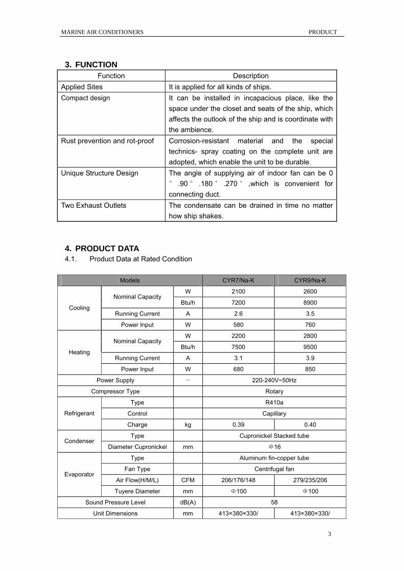
3. FUNCTION Function Description
Applied Sites It is applied for all kinds of ships. Compact design It can be installed in incapacious place, like the
space under the closet and seats of the ship, which affects the outlook of the ship and is coordinate with the ambience.
Rust prevention and rot-proof Corrosion-resistant material and the special technics- spray coating on the complete unit are adopted, which enable the unit to be durable.
Unique Structure Design The angle of supplying air of indoor fan can be 0° .90 ° .180 ° .270 ° ,which is convenient for connecting duct.
Two Exhaust Outlets The condensate can be drained in time no matter how ship shakes.
4. PRODUCT DATA 4.1. Product Data at Rated Condition
Models CYR7/Na-K CYR9/Na-K
W 2100 2600 Nominal Capacity
Btu/h 7200 8900
Running Current A 2.6 3.5 Cooling
Power Input W 580 760
W 2200 2800 Nominal Capacity
Btu/h 7500 9500
Running Current A 3.1 3.9 Heating
Power Input W 680 850
Power Supply - 220-240V~50Hz
Compressor Type Rotary
Type R410a
Control Capillary Refrigerant
Charge kg 0.39 0.40
Type Cupronickel Stacked tube Condenser
Diameter Cupronickel mm Φ16
Type Aluminum fin-copper tube
Fan Type Centrifugal fan
Air Flow(H/M/L) CFM 206/176/148 279/235/206 Evaporator
Tuyere Diameter mm Φ100 Φ100
Sound Pressure Level dB(A) 58
Unit Dimensions mm 413×380×330/ 413×380×330/

MARINE AIR CONDITIONERS PRODUCT
4
(Outline/Package) (H×W×D) 545×500×370 545×500×370
Weight(Net/Gross) kg 26.5/31.5 29/32.5
Models CYR12/Na-K CYR16/Na-K
W 3500 4600 Nominal Capacity
Btu/h 11900 15700
Running Current A 4.6 5.8 Cooling
Power Input W 950 1200
W 3800 4750 Nominal Capacity
Btu/h 13000 16200
Running Current A 5 6.7 Heating
Power Input W 1100 1400
Power Supply - 220-240V~50Hz
Compressor Type Rotary
Type R410a
Control Capillary Refrigerant
Charge kg 0.51 0.60
Type Cupronickel Stacked tube Condenser
Diameter Cupronickel mm Φ16
Type Aluminum fin-copper tube
Fan Type Centrifugal fan
Air Flow(H/M/L) CFM 325/282/235 395/353/323 Evaporator
Tuyere Diameter mm Φ125
Sound Pressure Level dB(A) 58
Unit Dimensions
(Outline/Package) (H×W×D) mm
468×380×330/
554×545×376
494×450×355/
622×590×400
Weight(Net/Gross) kg 32.5/38 38/43.5
Note:Fluctuation of the current and voltage can’t be beyond ±10%
1) Test Condition of Nominal Cooling Capacity: Indoor side-dry/wet bulb temp: 27/19.5℃; Water-in temp: Temp difference is 5℃ and static pressure is 0Pa;
2) Test Condition of Nominal Heating Capacity: Indoor side-dry/wet bulb temp: 20/15℃; Water-in temp: 15℃; Flow is as the test of nominal cooling capacity and static pressure is 0Pa;
3) Noise Measurement shall comply with JB/T4330-1999. 4) Input power excludes that of user’s water pump. 5) Specification will change with the revision of the product. Parameter on nameplate of the
unit is the standard.

MARINE AIR CONDITIONERS PRODUCT
5
4.2. Operation Range Water side Air side
Model Leaving Water
(℃/℉)
Temperature Difference
of Water(℃/℉)
Air on Condenser
(℃/℉)
Cooling 25 5 10~40
Heating 15 - 4~25
4.3. Electrical Data
Compressor
Power
Supply Qty. RLA LRA
Supply
Blower
Motor Model
V,Ph,Hz — Each Each Each RLA
CYR7/Na-K 3.05 12.4 0.64
CYR9/Na-K 4.05 19.6 0.86 CYR12/Na-K 5.55 25.0 0.59 CYR16/Na-K
220-240V 1Ph~50Hz 1
6.8 32 0.85 Notes:
RLA:Rated load amperes
LRA:Locked rotor amperes
5. PIPING DIAGRAM Name compresso
r 4-way valve
Stop Valve
Check Valve
Capillary Filter
ElectronicExpansio
n Valve
Symbol
Name
Temperature
Sensor
Pressure Switch
Heat Exchanger with Axial Flow Fan
Heat Exchange with CrossFlow Blower
Heat Exchanger with Centrifugal Fan
Thermal Expansion Valve
Vapour Liquid
Separator
Symbol
MARINE AIR CONDITIONERS PRODUCT
6
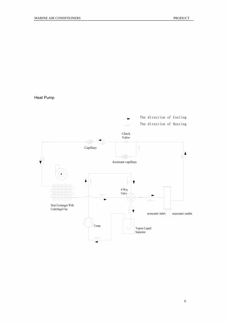
Heat Pump
The direction of Cooling
The direction of Heating
CheckValve
Capillary
Assistant capillary
seawater inlet seawater outlet

GREE COMMERCIAL AIR CONDITION MARINE AIR CONDITIONERS
7
CONTROL

MARINE AIR CONDITIONERS CONTROL
8
CONTROL 1. OPERATION FLOWCHART 1.1. Cooling/Dry Operation

MARINE AIR CONDITIONERS CONTROL
9
1.2. Heating Operation
2. MAIN LOGIC 2.1. Cooling/Dry Mode
(1)Cooling ON Condition: Compressor ON: Tamb≥Tset+1℃ and no error at the same time. When cooling is entered (they are just conditions for compressor ON, if they can’t be met, only indoor fan is running when startup of the unit while water pump and compressor are not running. Description

MARINE AIR CONDITIONERS CONTROL
10
1) Water pump starts up after the cooling command is sent. 2) After indoor fan has been running at high speed for 5s, it turns to low speed. 3) Compressor is ON after water pump has started up for 5s 4) 4-way valve closes.
Sequence Chart
Indoor Fan
Compressor
Send Command
Water Pump
4-way Valve
(2)Betweenness of Cooling
Condition: Tset-1℃<Tamb<Tset+1℃ Description 1) Indoor fan keeps the original status. 2) Water pump keeps the original status. 3) Compressor keeps the original status. 5)Other loads don’t need to work,
(3)Cooling OFF Condition: Tamb≤Tset-1℃ and no error at the same time ( if there is error, handle it according to troubleshooting sequence). Description 1) Indoor fan is running at setting speed. 2) Compressor stops 3) Water pump stops after the compressor has stopped for 5s.

MARINE AIR CONDITIONERS CONTROL
11
Sequence Chart
Indoor Fan
Compressor
Water Pump
4-way Valve
Send Command
(4)Cooling OFF Description 1) After the command is sent, the compressor stops. 2) Indoor unit and indoor fan stop at the same time. 3) 5s later water pump stops.
Sequence Chart
Indoor Fan
Compressor
Water Pump
4-way Valve
Send Command

MARINE AIR CONDITIONERS CONTROL
12
2.2. Heating Mode(Defrosting/ Auxiliary Electric Heater) (1)Heating ON Condition: Compressor ON: if Tamb≤Tset-1℃ and there is no error at the same time, the heating will be entered. Description 1) The indoor unit starts up when the command has been sent. 2) Water pump starts up at the same time. 3) Compressor starts up when the water pump has started up for 5s. 4) When compressor firstly starts up for 15s, 4-way valve is energized.
Sequence Chart
4-way Valve
Indoor Fan
Compressor
Water Pump
Send command
(2)Betweenness of Heating Condition: Tset-1℃<Tamb<Tset+1℃ and no error at the same time(( if there is error, handle it
according to troubleshooting sequence). Description 1) Indoor fan keeps original status. 2) Water pump keeps original status. 3) Compressor keeps original status. 4) 4-way valve keeps original status. (3)Heating OFF Condition Tamb≥Tset+1℃ and and no error at the same time(( if there is error, handle it according to troubleshooting sequence).

MARINE AIR CONDITIONERS CONTROL
13
Description 1) Indoor fan is running at setting speed. 2) Compressor stops. 3) 5s later, water pump stops. 4) 4-way valve keeps being energized. Sequence Chart
4-way Valve
Indoor Fan
Compressor
Water Pump
Send command
(4)Heating OFF Description 1) Compressor stops after command is sent. 2) 5s later, water pump stops. 3) 30s later after the stop of compressor, indoor fan stops. 4) 4-way valve is deenergized after the compressor has stopped for 2min.
Sequence Chart

MARINE AIR CONDITIONERS CONTROL
14
4-way Valve
Indoor Fan
Compressor
Water Pump
Send command
2.3. Fan Mode Indoor fan is running at setting speed and there are three options for the speed.
→ HIGH →MID → LOW → AUTO →
Auto Air Speed
a) Heating If Tamb≥Tset, it is automatically set to be low speed. If Tset-2℃<Tamb<Tset, it is automatically set to be mediate speed. If Tamb≤Tset-2℃, it is automatically set to be high speed.
During this course, there must be 30s delay at least. b) Cooling
If Tamb≤Tset℃, it is automatically set to be low speed. If Tset<Tamb<Tset+3℃ it is automatically set to be mediate speed.
If Tamb≥Tset+3℃ it is automatically set to be high speed.
3. REMOTE CONTROLLER 3.1. Wireless Remote Controller
3.1.1 Operation View

MARINE AIR CONDITIONERS CONTROL
15
ON/OFF
OPER
oF
MODE
NO. Name Function description
1 SWING button There is no swing function in this A/C unit.
2 TEMP button
TEMP. increase 1° by pressing + button once, and decreases 1° by pressing
- button once.
COOL MODE SET Temp. 61° F-86° F or 16° C-30° C
HEAT MODE SET Temp. 61° F-86° F or 16° C-30° C
DEHUMIDFY MODE 61° F-86° F or 16° C-30° C
3 MODE button
Press this button to change the operation mode in order of
Note: the cooling only without mode.
4 ON/OFF button Press this button to turn on or turn off the unit.
5 LCD It shows all the setting contents.
Note: Cover remove will not change the display contents.
6 FAN button Press this button to change the fan speed:

MARINE AIR CONDITIONERS CONTROL
16
3.1.2 Display View

MARINE AIR CONDITIONERS CONTROL
17
OPER
oF
NO. Display Function description
1 Fan speed display HIGH-MID-LOW and AUTO speed
2 Display of mode
operation
:Run automatically; :Cooling; :Dry;
:Only fan run; :Heating
Cooling only type without heat mode
3 Digital display Display of set temperature
4 Display of ON/OFF /
3.2. Wired Remote Controller
3.2.1 Operation View

MARINE AIR CONDITIONERS CONTROL
18
NO. Name Function description

MARINE AIR CONDITIONERS CONTROL
19
1 Remote receiver Receive the signal from the mainboard
2 Digital display Display of set temperature
3 Fan speed display Display of HIGH-MID-LOW or AUTO speed
4
Display of mode
operation
(COOL-DEHUMIDI
FY-HEAT and
AUTO)
In “COOL” mode, the LED marked will be light if the set
temperature is lower than room temperature. If set temperature is higher than room temperature, only the fan will run.
In “DEHUMIDIFY” mode, the LED marked will be light and fan will
work at low speed within a certain temperature range. Dehumidifying is more efficient than in cooling mode and it will save energy.
In “HEAT” mode, the LED marked will be light when the set
temperature is higher than the room temperature. When the setting temperature is lower than the room temperature, it will not run. In “FAN” mode, the room temperature will be displayed and the temperature cannot be set. In “AUTO” mode, the LED marked AUTO will be light and the room temperature will be displayed. The temperature cannot be set, as the system will run automatically in the appropriate mode according to the contrast between room temperature and set temperature.
5 Mode button
Press this key to change the operation mode in order of
→ COOL → DEHUMIDIFY → FAN → HEAT → AUTO →
6 Fan control button
Press the FAN button, the fan speed will change in the following order:
→ HIGH →MID → LOW → AUTO →
In “DEHUMIDIFY” mode, the fan will work at low speed automatically.
7 Temp. Setting
button (Increasing) To increase in 1o increments
8
Temp. Setting
button
(Decreasing) To decrease in 1o increments
9 ON/OFF button Press ON/OFF button to turn the unit on
Pressing the ON/OFF button a second time will turn the unit off
3.3. Display Fahrenheit or Centigrade
Pressing the ▲ and ▼ key simultaneously, will switch between Fahrenheit and Centigrade modes.

MARINE AIR CONDITIONERS CONTROL
20
3.4. Key Lock Press ▼and FAN key simultaneously, all keys are locked. Press ▼and FAN key simultaneously
again, to unlock the keys.
When keys are locked, the controller is locked out of system operation. “EE” will be displayed.
3.5. Starting Interval Setting If there are several A/C units in a yacht, you can set starting time interval between one by one.
When the manual controller power on, and there isn’t any operation, to press
the ▲ button and fan speed button simultaneously, the starting interval can be set, the nixie
tube will flash a number in every 0.5s, then pressing ▼ and ▲ buttons to set up, after the
setting, to press the ▲ button and fan speed button simultaneously, to confirm the set up value;
if not to press▲ button and fan button again simultaneously, the figure will flash 10s,and then
the controller will quit from starting interval setting, the setting number is not available.
The value be displayed by nixie tube is the figure of interval time, each interval time is 20s, for
example the set up value is 128, it means that the actual setting interval time should be
128×20=2560s.
When the value be displayed by flashing nixie tube, then to shield each signal of wireless
remote controller, excepting to press the ▲ button and fan speed button at the same time, and
to shield other buttons.
After manual controller powered on, if there is wireless remote controller or at the same time to
press other buttons except the ▲ button and fan speed button simultaneously, and then press
the ▲ button and fan speed button simultaneously, it will display the figure of interval time for 5s.
During the period, if there is wireless remote controller or other remote controller signal, it will
directly quit the display interface of starting interval time.
The new setting starting interval time would be executed after manual controller re-powered on.
The setting range of starting interval value is 0-255; accordingly, the setting range of starting
interval time is 0-5100s(85min).
If there is malfunction happened, cannot set up or display the time of starting interval.
3.6. Auto –off function of the manual controller The display of ambient temperature will automatically blank in 5-minute lag if there is no operation on
the manual controller.
(1)After receiving the signal from the manual controller, the indicator will light on automatically, in
which case, the unit will not operation at all and the manual controller can be active after it lights on.
(2) After receiving the signal from remote controller, the display of temperature on the manual
controller will light on; meanwhile, the unit carries out corresponding operation.
After the unit stops, there is no display on the manual controller.
Powered on again if the unit status is on before power off, temperature indicator and mode
indicator of the manual controller will light on automatically.
If the unit receives the stop signal, it will directly blank off the temperature indicator and mode
indicator of the manual controller.

MARINE AIR CONDITIONERS CONTROL
21
3.7. Dimension
(19m
m)
AUTOAUTO
FAN MODE
ML
H
3.8. Installation Before mounting the manual controller, consider the location. The manual controller should be mounted
on an inside wall, slightly higher than mid-height of the cabin. The cut out size for the manual controller is
2 1/2” (64mm) wide by 3 5/16” (84mm). Do not mount the manual controller in direct sunlight, near any
heat producing appliances or in a bulkhead where temperatures radiating from behind the panel may
affect performance. Do not mount the manual controller in the supply air stream. Do not mount the
manual controller above or below a supply or return air grille. Do not mount the manual controller behind
a door, in a corner, under a stairwell or any place where there is no freely circulating air. Mount the
manual controller within display cable length (custom lengths available) of the air conditioner. Plug the
display cable into the circuit board in the electric box and into the back of the manual controller.
GREE COMMERCIAL AIR CONDITION MARINE AIR CONDITIONERS
22
INSTALLATION

MARINE AIR CONDITIONERS INSTALLATION
23
INSTALLATION 1. Dimension Data
Model H A B C D
CYR7/Na-K 331 386 383 120 16
CYR9/Na-K 331 395 383 120 16
CYR12/Na-K 331 441 383 150 16
CYR16/Na-K 358 475 455 150 16
2. Installation Clearance Data
wall
wall
wall wall

MARINE AIR CONDITIONERS INSTALLATION
24
wall
Note: Air outlets on bottom and both sides shall be away from the ceiling for 40mm at least; Air outlet
shall be away from the ceiling for 100mm at least.
Drain Piping Work The condensate drain pan is 2” (50mm) high with two drain locations. During conditions of high humidity,
condensate may be produced at a rate of approximately 1/2 gallon per hour (1.9 liters per hour). Please
pay more attention, it is important to route condensate drains downward to a sump pump. It is not
recommended to route condensate drains to the bilge. After the condensate drain installation is complete,
test the installation by pouring water into the pan and checking for good flow.
For installation of the condensate drain:
● Attach a 5/8” I.D. reinforced hose to the hose barb and secure with stainless steel hose clamps.
● Install the condensate drain hose downhill from the unit and aft to a sump.
● Two drain fittings may be used and the hoses (teed) together using a tee fitting provided there
is a minimum 2" drop from the bottom of the base pan to the tee connection.
Do not terminate condensate drain line within three 3’ (914mm) of any outlet of engine,
generator exhaust systems, compartment housing an engine or generator, nor in a bilge,
unless the drain is connected properly to a sealed condensate or shower sump pump.
Seal all condensate hose penetrations.
3. Unit Installation Selecting a good location for your air conditioner is the most important part of your preparation. Be sure to consider the size of the area you are cooling, the air distribution needs, and the size of the unit you have chosen. Keeping in mind that cool air has a tendency to fall; it is highly recommended that you locate the supply air grille as high as possible in the cabin. See diagram below.

MARINE AIR CONDITIONERS INSTALLATION
25
The unit should be installed as low as possible, BUT NEVER IN THE BILGE OR ENGINE
ROOM AREAS, ENSURE THAT THE SELECTED LOCATION IS SEALED FROM DIRECT
ACCESS TO BILGE AND/OR ENGINE ROOM VAPORS. Installing the unit as low as possible (such as under a V-berth, dinette seat or bottom of a locker) and ducting the supply air as high as possible, creates an ideal airflow condition. This type of installation will prevent short or premature cycling.
The unit should be positioned on a firm, level, horizontal surface and the condensate drain line should run downward from the unit to a suitable drain location. Plan all Connections, which must be made including ducting, condensate drain, and seawater in and out, electrical power connections, location of control, and seawater pump placement, to assure easy access for routing and servicing.
4. Water System Installation Several guidelines should be followed during the installation of the seawater system. Since the circulation pump is centrifugal and not self-priming, it must be mounted so that it is always at least 1’ (305mm) below the water line regardless of which tack the vessel is on. Pump may be mounted horizontally or vertically, however, the discharge must always be above the inlet. Pump head should be rotated toward the direction of water flow. Install the seawater speed scoop intake as far below the water line and as close to the keel as possible in any application,

MARINE AIR CONDITIONERS INSTALLATION
26
but especially on a sailboat, to keep the intake in the water when the boat heels over so that air does not get into the system. The speed scoop intake must face forward and not be shared with any other pump. A seawater strainer is mandatory between the shut off valve (seacock) and the pump to protect the pump from any foreign matter. Failure to install a seawater strainer will void the pump warranty. The seawater system should be installed with an upward incline from the speed scoop & seacock, through the strainer, to the inlet of the pump, next to the inlet of the a/c unit's condenser coil. The discharge from the a/c unit should run to the seawater outlet thru-hull fitting that should be located where it can be visually inspected for water flow as close to the waterline to reduce noise. All hose connections shall be secured using double/reversed stainless steel hose clamps. Use Teflon tape on all threaded connections.
Summary of the seawater system installation:
1. Install the speed scoop thru-hull inlet as close to the keel and as far below the water line as possible, facing forward. Bed the scoop with a marine sealant designed for underwater use.
2. Install a bronze, full flow seacock on the speed scoop thru-hull inlet. 3. Install a seawater strainer below the level of the pump with access to filter. 4. Mount the pump above the strainer and at least 1’ (305mm) below the waterline. 5. Connect the seacock and strainer with an uphill run of 5/8" reinforced marine grade
hose. 6. Connect the discharge from the pump uphill to the bottom inlet of the a/c unit's
condenser coil with 5/8" hose. Connect the discharge from the condenser coil to the overboard discharge thru-hull fitting with 5/8" hose.
7. Avoid loops, high spots or the use of 90° elbows with seawater hose (each 90° elbow is equivalent to 2.5' (762mm) of hose and a 90° elbow on the pump outlet is equivalent to 20' (6.1m) of hose).
8. Double clamp all hose connections with stainless steel clamps, reversing the clamps. 9. Use Teflon tape on all threaded connections. 10. Connect all metallic parts in contact with seawater to the vessel's bonding system
including the speed scoop inlet, strainer, pump and the air conditioner. Failure to do so will void warranty.

MARINE AIR CONDITIONERS INSTALLATION
27
5. ELECTRIC WIRING WORK 5.1. Electric Wiring Design
Mainboard
Power
Connect water circulating pump
Connect wired controller
5.2. Specification of Power Supply Wire and Air Switch
Model Power Supply Capability of Minimum Minimum Sectional

MARINE AIR CONDITIONERS INSTALLATION
28
Air Switch Sectional Area of
Earth Wire
Area of Power
Supply Wire
V Ph Hz (A) (mm2) (mm2)
CYR7/Na-K 6 1.0 1.0
CYR9/Na-K 6 1.0 1.0
CYR12/Na-K 10 1.5 1.5
CYR16/Na-K
220-240V 1Ph
50Hz
10 1.5 1.5

MARINE AIR CONDITIONERS MAINTENANCE
29
MAINTENANCE

MARINE AIR CONDITIONERS MAINTENANCE
30
MAINTENANCE 1. TROUBLE TABLE Trouble Code
Trouble Name
Origin of Trouble Signal
Control Description
E1
High Pressure
Protection of
Compressor
High Pressure Switch
When high pressure is detected for
continuous 3s, turn off the system( 4
way-valve is excluded when heating), and
“E1” will be displayed. It cannot be
recovered. “E1” is cleared by pressing
button “ON/OFF”. Press ON/OFF again to
resume running.
E2 Indoor Antifreezing
Protection Temp Sensor
Under Cool or Dry mode, after the
compressor has been running for
continuous 15min, if Teva <-2℃ is detected
for continuous 3min, compressor will stop,
fan will keep original status, nixie display
indicator will display “E2”. When Teva ≥10
℃ for continuous 1s, it will recover and
system will work normally.
E3
Low Pressure
Protection of
Compressor
Low Pressure
Switch
After 4min startup of compressor, detection
for low pressure is executed. When detect
that the low pressure switch breaks for 30s,
the system is turned off (4-way valve is
excluded when heating and indoor fan stops
after the compressor has stopped for 30s.),
E3 is displayed and buzzer is warning. It
can’t recover automatically. Press ON/OFF
to clear the warning of voice.
E6 Communication Error
Protection
When communication error has been
detected for 1min, system is turned off
94-way valve is excluded when heating and
indoor fan stops after the compressor has
stopped for 30s.)and E6 is displayed. After
the communication turns to normal, system
resumes running and error code is cleared.
F0 Indoor Ambient Temp
Sensor Error Temp Sensor
When detect that AD value is greater than
250 (short circuit) or less than 5 (open
circuit) for continuous 5s, it is believed that
the temp sensor is error. If detect that the

MARINE AIR CONDITIONERS MAINTENANCE
31
AD value is between 5 and 250 for
continuous 5s, it is believed that the temp
sensor recovers.
When there is error of temp senor, system is
turned off (4-way valve is excluded when
heating and indoor fan stops after the
compressor has stopped for 30s) and F0 is
displayed. It can resume running when the
error is cleared. Under air supply mode, only
error code is displayed and the fan works
normally. The error code will disappear
when the error is cleared.
F1 Evaporator Temp
Sensor Error Temp Sensor
When detect that AD value is greater than
250 (short circuit) or less than 5 (open
circuit) for continuous 5s, it is believed that
the temp sensor is error. If detect that the
AD value is between 5 and 250 for
continuous 5s, it is believed that the temp
sensor recovers
When there is error of temp sensor, the
system is turned off (4-way valve is
excluded when heating and indoor fan stops
after the compressor has stopped for 30s.)
and F1 is displayed. After the error is
cleared, it resumes running. Under air
supply mode, only error code is displayed
and fan works normally. When error is
cleared, error code will disappear.

MARINE AIR CONDITIONERS MAINTENANCE
32
2. FLOW CHART OF TROUBLESHOOTING 2.1. High Pressure Protection
Check if the pressure is
high by manometer
High Pressure Protection
Replace mainboard
Check if the mainboard is
normal
Check if the setting for
running mode of the unit is proper
Adjust the setting mode
Check if the fan works normally
Check fan motor and the signal input
Check if the components for throttling are blocked
Replace the components
No No
Yes
No
No
Yes
No
Yes

MARINE AIR CONDITIONERS MAINTENANCE
33
2.2. Low Pressure Protection
MARINE AIR CONDITIONERS MAINTENANCE
34
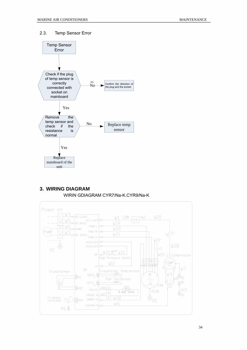
2.3. Temp Sensor Error
Check if the plug of temp sensor is
correctly connected with
socket on mainboard
Temp Sensor Error
Remove the temp sensor and check if the resistance is normal
Replace temp sensor
否
No
Yes
No Confirm the direction of the plug and the socket
Replace mainboard of the
unit
Yes
3. WIRING DIAGRAM
WIRIN GDIAGRAM CYR7/Na-K.CYR9/Na-K

MARINE AIR CONDITIONERS MAINTENANCE
35
WIRIN GDIAGRAM CYR12/Na-K.CYR16/Na-K

MARINE AIR CONDITIONERS MAINTENANCE
36
4. DISASSEMBLY AND ASSEMBLY PROCEDURE OF MAIN PARTS 4.1. Compressor
Disassembly and Assembly of Compressor
Remark : Make sure that there isn’t any refrigerant in pipe system and the power supply is cut off before
removal of the compressor.
Process Pictorial View Handling Description
1 . Disconnect
the power cord
●Unscrew the retaining screw
of power cord with
screwdriver.
●Unplug the power cord.
2. Disassemble
retaining nut
●Unscrew retaining nut by
screwdriver.
3. Disassemble
the discharge
pipe and the
suction and
discharge pipe of
compressor.
●Heating suction and
discharge pipe by acetylene
welding and then unplug them
from compressor.
●Conduct nitrogen-fill
protection on process pipe
and the pressure of nitrogen is
0.5±0.1kgf/c ㎡ ( relative
pressure).
●Heat it with caution in case
the surroundings get burnt
due to high temperature
4 . Remove
compressor
● Remove the compressor
from chassis.

MARINE AIR CONDITIONERS MAINTENANCE
37
5. Fix the new
compressor on
chassis.
●Place the new compressor
on the accurate position
●Screw up retaining bolts of
compressor
●Don’t inversely place the
compressor
6. Connect the
inlet and outlet of
compressor
with pipeline of
system.
●Weld suction and discharge
pipe by acetylene welding
●Conduct nitrogen-fill
protection on process pipe
and the pressure of nitrogen is
0.5±0.1kgf/c ㎡ ( relative
pressure).
●Heat it with caution in case
the surroundings get burnt
due to high temperature
7 . Connect
power cord of
compressor
●Connect the power cord to
retaining bolts according to
disassebly sequence.
●Screw the bolts tightly.
8 . Vacuumize
system by
feeding fluorin
nozzle.
●Vacuumize system by
feeding fluorin nozzle.
●
9 . Charge
refrigerants again
by feeding fluorin
nozzle.
●Charge refrigerants again by
feeding fluorin nozzle.
●Charge volume must comply
with the nameplate.

MARINE AIR CONDITIONERS MAINTENANCE
38
4.2. The 4-way valve Disassembly and Assembly of the 4-way valve
Remark : Make sure that there isn’t any refrigerant in pipe system and the power supply is cut off before
removal of the thermal expansion valve.
Process Pictorial View Handling Description
1. Disassemble
electromagnetic valve.
●Dismantle
electromagnetic valve
with spanner.
●Remove
electromagnetic valve
from 4-way valve.
2. Dismantle 4-way
valve.
●Heat connecting
pipe of 4 vents of
4-way valve by gas
welding and then
unplug 4-way valve.
●nitrogen-fill
protection shall be
conducted on welding
joint and the pressure
of nitrogen is
0.5±0.1kgf/c ㎡
( relative pressure)
●Record the direction
of 4-way valve and the
position of each vent
before remove 4-way
valve.

MARINE AIR CONDITIONERS MAINTENANCE
39
3. Remove 4-way valve
●Remove old 4-way
valve from pipeline.
4. Install new 4-way
valve.
●Install the new 4-way
valve in correct
position and connect it
with pipeline correctly.
●Wrap the valve with
wet cloth when
welding to prevent the
slide block inside the
valve from burning
and prevent water
from piping.
●Charge nitrogen to
weld and the nitrogen
pressure is
0.5±0.1kgf/c ㎡
( relative pressure)
5. Install
electromagnetic valve.
●Install the
electromagnetic valve
in new 4-way valve.
6. Inspect the system
and charge
refrigerants.
●Vacuumize and
charge refrigerants
after confirmation that
there is no leakage of
the system.
MARINE AIR CONDITIONERS MAINTENANCE
40
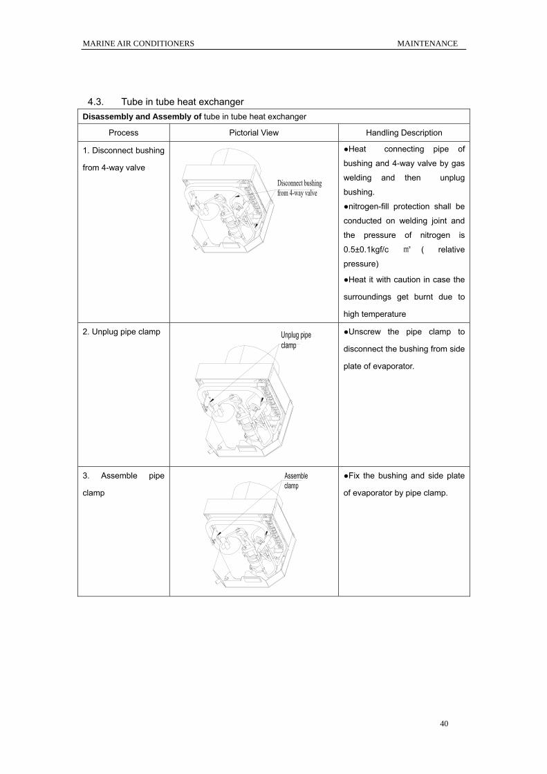
4.3. Tube in tube heat exchanger Disassembly and Assembly of tube in tube heat exchanger
Process Pictorial View Handling Description
1. Disconnect bushing
from 4-way valve
●Heat connecting pipe of
bushing and 4-way valve by gas
welding and then unplug
bushing.
●nitrogen-fill protection shall be
conducted on welding joint and
the pressure of nitrogen is
0.5±0.1kgf/c ㎡ ( relative
pressure)
●Heat it with caution in case the
surroundings get burnt due to
high temperature
2. Unplug pipe clamp
●Unscrew the pipe clamp to
disconnect the bushing from side
plate of evaporator.
3. Assemble pipe
clamp
●Fix the bushing and side plate
of evaporator by pipe clamp.

MARINE AIR CONDITIONERS MAINTENANCE
41
4. Connect the
bushing with pipeline
of 4-way valve
●Weld bushing by gas welding.
●nitrogen-fill protection shall be
conducted on welding joint and
the pressure of nitrogen is
0.5±0.1kgf/c ㎡ ( relative
pressure)
●Heat it with caution in case the
surroundings get burnt due to
high temperature
4.4. Fan and Fan Motor
Disassembly and Assembly of Fan and Fan Motor
Process Pictorial View Handling Description
1. Disassemble fan
●Disassemble fan by
screwdriver.
2. Install fan
●Fix the fan by screwdriver.
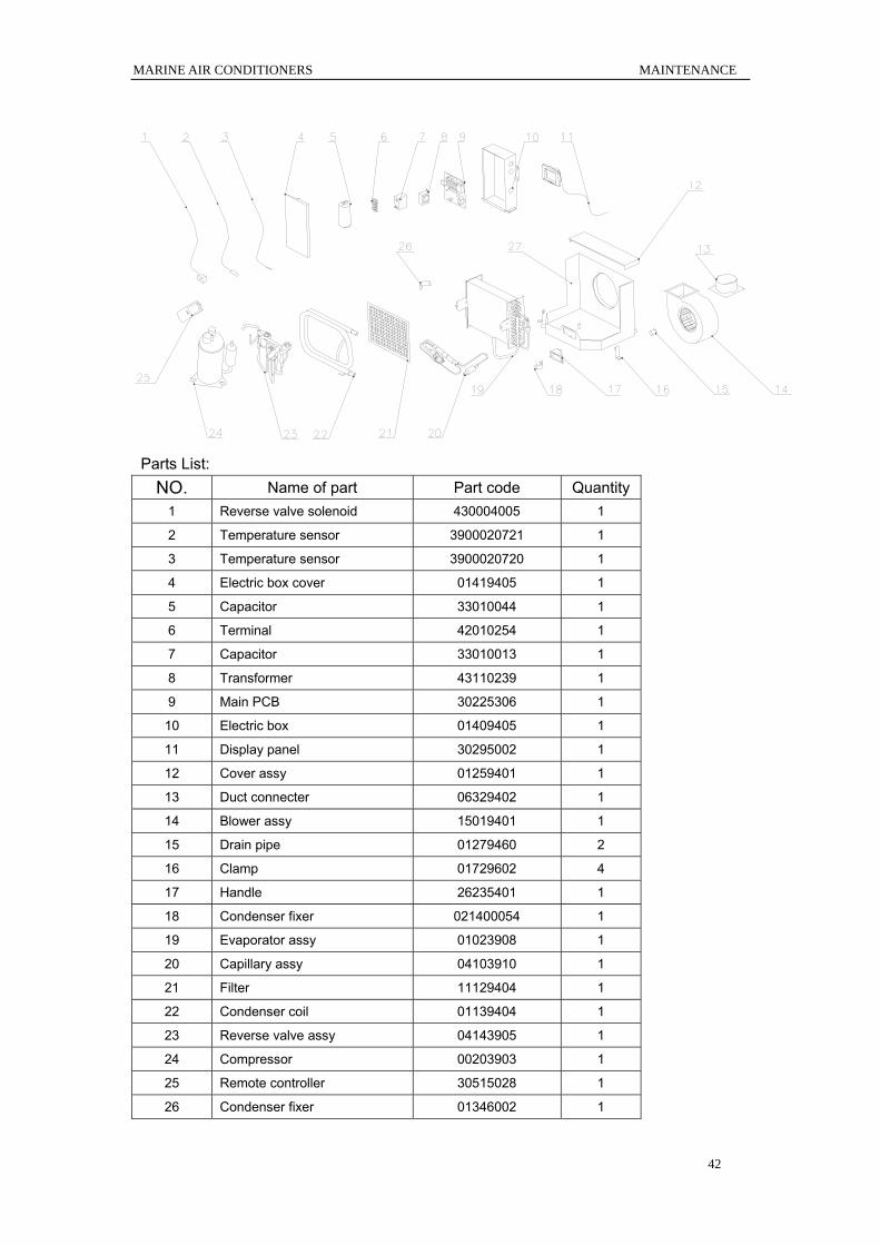
5. EXPLODED VIEWS AND PART LIST 1) Model: CYR7NaK
Exploded View:
MARINE AIR CONDITIONERS MAINTENANCE
42
Parts List: NO. Name of part Part code Quantity
1 Reverse valve solenoid 430004005 1
2 Temperature sensor 3900020721 1
3 Temperature sensor 3900020720 1
4 Electric box cover 01419405 1
5 Capacitor 33010044 1
6 Terminal 42010254 1
7 Capacitor 33010013 1
8 Transformer 43110239 1
9 Main PCB 30225306 1
10 Electric box 01409405 1
11 Display panel 30295002 1
12 Cover assy 01259401 1
13 Duct connecter 06329402 1
14 Blower assy 15019401 1
15 Drain pipe 01279460 2
16 Clamp 01729602 4
17 Handle 26235401 1
18 Condenser fixer 021400054 1
19 Evaporator assy 01023908 1
20 Capillary assy 04103910 1
21 Filter 11129404 1
22 Condenser coil 01139404 1
23 Reverse valve assy 04143905 1
24 Compressor 00203903 1
25 Remote controller 30515028 1
26 Condenser fixer 01346002 1

MARINE AIR CONDITIONERS MAINTENANCE
43
27 Base/pan 01283929 1
2) Model: CYR9NaK
Exploded View:
Parts List: NO. Name of part Part code Quantity
1 Reverse valve solenoid 430004005 1
2 Temperature sensor 3900020721 1
3 Temperature sensor 3900020720 1
4 Electric box cover 01419405 1
5 Capacitor 33000018 1
6 Terminal 42010254 1
7 Capacitor 33010013 1
8 Transformer 43110239 1
9 Main PCB 30225306 1
10 Electric box 01409405 1
11 Display panel 30295002 1
12 Cover assy 01259401 1
13 Duct connecter 06329401 1
14 Blower assy 150194014 1
15 Drain pipe 01279460 2
16 Clamp 01729602 4
17 Handle 26235401 1
18 Condenser fixer 021400054 1
19 Evaporator assy 01009401 1

MARINE AIR CONDITIONERS MAINTENANCE
44
20 Capillary assy 03009405 1
21 Filter 11129404 1
22 Condenser coil 01139401 1
23 Reverse valve assy 04143903 1
24 Compressor 00120084 1
25 Remote controller 30515028 1
26 Condenser fixer 01346002 1
27 Base/pan 01283921 1
3) Model: CYR12NaK Exploded View:
NO. Name of part Part code Quantity 1 Reverse valve solenoid 430004005 1
2 Temperature sensor 3900020721 1
3 Temperature sensor 3900020720 1
4 Electric box cover 01419405 1
5 Capacitor 33010743 1
6 Terminal 42010254 1
7 Capacitor 33010010 1
8 Transformer 43110239 1
9 Main PCB 30225306 1
10 Electric box 01409405 1
11 Display panel 30295002 1
12 Cover assy 01259401 1

MARINE AIR CONDITIONERS MAINTENANCE
45
13 Duct connecter 06329402 1
14 Blower assy 150094065 1
15 Drain pipe 01279460 2
16 Clamp 01729602 4
17 Handle 26235401 1
18 Condenser fixer 021400054 1
19 Evaporator assy 01023907 1
20 Capillary assy 04103908 1
21 Filter 11129403 1
22 Condenser coil 01139404 1
23 Reverse valve assy 04143903 1
24 Compressor 00120084 1
25 Remote controller 30515028 1
26 Condenser fixer 01346002 1
27 Base/pan 01283916 1
4) Model: CYR16NaK Exploded View:
NO. Name of part Part code Quantity 1 Reverse valve solenoid 430004005 1
2 Temperature sensor 3900020721 1
3 Temperature sensor 3900020720 1
4 Electric box cover 01419405 1
5 Capacitor 33010743 1
6 Terminal 42010254 1
7 Capacitor 33010013 1
MARINE AIR CONDITIONERS MAINTENANCE
46
8 Transformer 43110239 1
9 Main PCB 30225306 1
10 Electric box 01409405 1
11 Display panel 30295002 1
12 Cover assy 01259404 1
13 Duct connecter 06329402 1
14 Blower assy 150094064 1
15 Drain pipe 01279460 2
16 Clamp 01729602 4
17 Handle 26235401 1
18 Condenser fixer 021400054 1
19 Evaporator assy 01039405 1
20 Capillary assy 04103909 1
21 Filter 11129402 1
22 Condenser coil 01139405 1
23 Reverse valve assy 04143902 1
24 Compressor 00120023 1
25 Remote controller 30515028 1
26 Condenser fixer 01346004 1
27 Base/pan 01283918 1
PDM S/N:JF00300224