jeppiaar engineering collegedl.icdst.org/pdfs/files1/e4df1a8bfbf029416156ec82c25ee9c...jeppiaar...
TRANSCRIPT
JEPPIAAR ENGINEERING COLLEGE
QUESTION BANK
UNIT I SIGNALS AND SYSTEMS 9 Basic elements of DSP – concepts of frequency in Analog and Digital Signals – sampling theorem – Discrete – time signals, systems – Analysis of discrete time LTI systems – Z transform – Convolution (linear and circular) – Correlation.
UNIT II FREQUENCY TRANSFORMATIONS 9 Introduction to DFT – Properties of DFT – Filtering methods based on DFT – FFT Algorithms Decimation – in – time Algorithms, Decimation – in – frequency Algorithms – Use of FFT in Linear Filtering – DCT.
UNIT III IIR FILTER DESIGN 9 Structures of IIR – Analog filter design – Discrete time IIR filter from analog filter – IIR filter design by Impulse Invariance, Bilinear transformation, Approximation of derivatives – (HPF, BPF, BRF) filter design using frequency translation
UNIT IV FIR FILTER DESIGN 9 Structures of FIR – Linear phase FIR filter – Filter design using windowing techniques, Frequency sampling techniques – Finite word length effects in digital Filters
UNIT V APPLICATIONS 9 Multirate signal processing – Speech compression – Adaptive filter – Musical sound processing – Image enhancement.
TEXT BOOKS:
1. John G. Proakis & Dimitris G.Manolakis, “Digital Signal Processing – Principles, Algorithms & Applications”, Fourth edition, Pearson education / Prentice Hall, 2007.
2. Emmanuel C..Ifeachor, & Barrie.W.Jervis, “Digital Signal Processing”, Second edition, Pearson Education / Prentice Hall, 2002.
REFERENCES:
3. Alan V.Oppenheim, Ronald W. Schafer & Hohn. R.Back, “Discrete Time Signal Processing”, Pearson Education.
4. Andreas Antoniou, “Digital Signal Processing”, Tata McGraw Hill.
CS 2403 – DIGITAL SIGNAL PROCESSING
www.vidyarthiplus.com
UNIT I - SIGNALS ANS SYTEMS
1. What are energy and power signals?
The energy signal is one in which has finite energy and zero
average power. The power signal is one in which has finite average
power and infinite energy.
T
E = Lt ∫ │x(t)│2 dt joules .
T→∞ -T
P = Lt T
T→∞ 1 / 2T ∫ │x(t)│2 dt joules .
2. What are Random signals?
The signal that takes on random value at any given instant and it
cannot be predicted. Non deterministic signals are also called as
Random signals.
Example: ECG signals, Noise in electric circuits.
3. Distinguish between continuous and discrete time signals.
If the signal amplitude can be defined for all values of time t is
Called as continuous time signals and it is denoted by x(t).
If the signal amplitude can be defined for particular integer values of
time period n is called as discrete time signals and it is denoted by
x(n).
4. Find the period of x(n) = cos [8πn/7 +2].
ω = 8π/7 2πf = 8π/7
f= 4/7 ; here K= 4 & N =7
It is periodic and the fundamental period is N =7 samples.
5. Define System.
A system is a physical device that performs an operation on the
signal. The input signal is called as excitation and output signal is
called as response.
6. State the classification of system. (Nov/Dec 2004)
I. Linear and non linear system
www.vidyarthiplus.com

II. Time variant and in variant system
III. Causal and non causal system.
IV. Static and Dynamic system.
V. Stable and unstable system.
7. Distinguish between linear and non linear system.
a1 y1(t) + a2 y2(t) = f[a1x1(t) + a2x2(t)]
If the above equation satisfies then the system is said to be linear
system. If the above equation does not satisfy then the system is said
to be non linear system.
8. State the properties of linear system.
A system is said to be linear it should satisfy the principle of
Superposition.
9. Define time invariant system. (May/June 2006)
A system is time invariant if it satisfies the following relation
F[ x(t – t1)] = y(t – t1).
10. What is meant by causal & non causal system? (May/June 2006)
A system is said be causal if it’s output at anytime depends
upon present and past input only. A system is said be non causal if it’s
output at anytime depends upon present and future input only.
11. State the condition for the BIBO stable? May/June 2005
The condition for the BIBO stable is given by
∞
∫ │h (t)│dt < ª
12. Define Z- Transform.
The Z – transform of a discrete time signal x(n) is defined as
the power series α
Z[x(n)] = X(z) = Σ x(n) z-n
n= -α
13. Define Sampling Theorem. Nov/Dec 2008
Sampling is the process by which analog signal is converted
into corresponding sequence of samples that are spaced uniformly in
time.
www.vidyarthiplus.com

14. What is aliasing?
The phenomenon of high frequency sinusoidal components
acquiring the identity of low frequency sinusoidal components after
sampling is called aliasing.
15. Check whether the system y(n) = e
x(n) is linear. May/June 2007
Consider two signals x1(n) and x2(n).Let
y1(n) & y2(n) be the
response of the system for inputs x1(n) and x2(n) respectively.
y1(n) = H[x1(n)] = e x1
(n)
y2(n) = H[x2(n)] = e x2
(n)
y3(n) = H[a1x1(n) +a2 x2(n)] = e (a
1x1
(n) + a2
x2
(n)) = e
a1
x1
(n) .
e
a2
x2
(n))
Therefore, a1y1(n) + a2y2(n) = a1ex1
(n) + a2 e
x2
(n)
y3(n) is not equal to a1y1(n) + a2y2(n). Hence the system is non linear.
PART-B
1) Determine whether the following signals are linear,time
variant, causal and stable. Nov/Dec 2008
Y(n) = Cos[x(n)]
Y(n) = x(-n+2)
Y(n) = x(2n)
Y(n) = x(n) + nx(n+1)
Ans: Ref Pg.No 31-45 , DSP by Nagoor Kani.A
2) Find the response of the system for the input signal
X(n) = {1,2,2,3} and h(n) = {1,0,3,2} May/June 2007
Ans: Ref Pg.No 164 , DSP by Nagoor Kani.A
3) Explain sampling theorem
Ans: Ref Pg.No 26 , DSP by Proakis
4) Find the inverse z- transform of May/June 2007
1/ (1-0.5 z-1
) (1-z-1
)
Ans: Ref Pg.No 461, DSP by Nagoor Kani.A
5) Perform circular convolution of the two sequences.
X1(n) = {2,1,2,1}
X2(n) = {1,2,3,4}
Ans: Ref Pg.No 175, DSP by Nagoor Kani.A
www.vidyarthiplus.com
UNIT II - FREQUENCY TRANSFORMATION
PART-A
1. State and prove Parseval’s Theorem. Nov/Dec 2007
Parseval’s theorem states that
If x(n) ↔ X(K) and y(n) ↔ Y(K) , Then
N-1 N-1
∑ x(n) y*(n) = 1/N ∑ X(K) Y*(K)
n=0 K =0
When y(n) = x(n), the above equation becomes
2. . What do you mean by the term “bit reversal” as applied to FFT?
Nov/Dec 2007
Re-ordering of input sequence is required in decimation – in –time.
When represented in binary notation sequence index appears as
reversed bit order of row number.
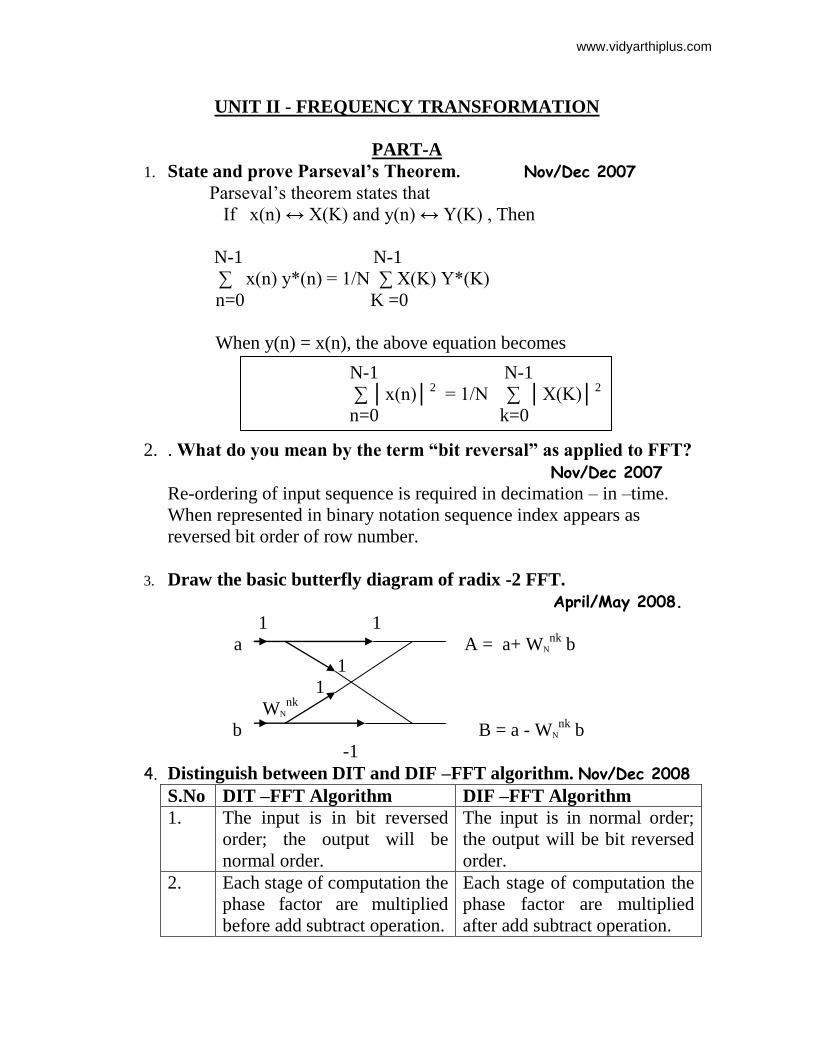
3. Draw the basic butterfly diagram of radix -2 FFT.
April/May 2008.
1 1
a A = a+ WN
nk b
1
1
WN
nk
b B = a - WN
nk b
-1
4. Distinguish between DIT and DIF –FFT algorithm. Nov/Dec 2008
S.No DIT –FFT Algorithm DIF –FFT Algorithm
1. The input is in bit reversed
order; the output will be
normal order.
The input is in normal order;
the output will be bit reversed
order.
2. Each stage of computation the
phase factor are multiplied
before add subtract operation.
Each stage of computation the
phase factor are multiplied
after add subtract operation.
N-1 N-1
∑ │x(n)│2 = 1/N ∑ │X(K)│
2
n=0 k=0
www.vidyarthiplus.com
5. If H(K) is the N-point DFT of a sequence h(n) , Prove that H(K)
and H(N-K) are comples conjugates. Nov/Dec 2008
This property states that, if h(n) is real , then
H(N-K) = H*(K) = H(-K)
Proof:
By the definition of DFT;
N-1
X(K) = ∑ x(n) e (–j2πnk)/N
n=0
Replace ‘K’ by ‘N-K’
N-1
X(N-K) = ∑ x(n) e (–j2πn(N-K))/N
n=
6. The first five DFT coefficients of a sequence x(n) are X(0) = 20,
X(1) = 5+j2,X(2) = 0,X(3) = 0.2+j0.4 , X(4) = 0 . Determine the
remaining DFT coefficients. May/June 2007
Solution:
X (K) = [20, 5+j2, 0, 0.2+j 0.4 , 0,X(5),X(6),X(7)]
X (5) = 0.2 – j0.4
X (6) = 0
X (7) = 5-j2
7. What is FFT? Nov/Dec 2006 The Fast Fourier Transform is a method or algorithm for computing
the DFT with reduced number of calculations. The computational
efficiency can be achieved if we adopt a divider and conquer
approach. This approach is based on decomposition of an N-point
DFT in to sucessively smaller DFT’s. This approach leads to a family
of an efficient computational algorithm is known as FFT algorithm.
8. What are the advantages of FFT algorithm over direct
computation of DFT? May/June 2007
1. Reduces the computation time required by DFT.
2. Complex multiplication required for direct computation is N2
and for FFT calculation is N/2 log 2 N.
Speed calculation
X(N-K) = X*(K)
www.vidyarthiplus.com
9. Define the properties of convolution. April/May 2008.
3. Commutative property: x(n)*h(n) = h(n) *x(n)
4. Associative Property: [x(n)*h1(n)] *h2(n) = x(n)*[h1(n)*h2(n)]
5. Distributive Property: x(n)*[ h1(n)+ h2(n)] = [x(n)* h1(n)]+ [x(n)*
h1(n)]
10. Distinguish between linear & circular convolution.
s.no Linear convolution circular convolution
1 The length of the input sequence
can be different.
The length of the input
sequence should be same.
2 Zero Padding is not required. Zero padding is required if
the length of the sequence is
different.
11. Define Zero padding? Why it is needed?
Appending zeros to the sequence in order to increase the size or length
of the sequence is called zero padding.In circular convolution , when
the two input sequence are of different size , then they are converted
to equal size by zero padding.
12. State the shifting property of DFT.
Time shifting property states that
DFT {x(n-n0)} = X(K) e (–j2πn0k)/N
13. Why do we go for FFT?
The FFT is needed to compute DFT with reduced number of
calculations.The DFT is required for spectrum analysis on the sinals
using digital computers.
14. What do you mean by radix-2 FFT?
The radix -2 FFT is an efficient algorithm for coputing N- point DFT
of an N-point sequence .In radix-2 FFT the n-point is decimated into
2-point sequence and the 2-point DFT for each decimated sequence is
computed. From the results of 2-point DFT’s, the 4-point DFT’s are
computed. From the results of 4 –point DFT’s ,the 8-point DFT’s are
computed and so on until we get N - point DFT.
www.vidyarthiplus.com
15. Give any two application of DFT?
1. The DFT is used for spectral analysis of signals using a digital
computer.
2. The DFT is used to perform filtering operations on signals
using digital computer.
16. How many multiplications & addition are involved in radix-2
FFT?
For performing radix-2 FFT, the value of Nshould be such that, N=
2m. The total numbers of complex additions are Nlog 2 N and the total
number of complex multiplication are (N/2) log 2 N.
17. What is Twiddle factor?
Twiddle factor is defined as WN = e –j2π/N.
It is also called as weight
factor.
18. What is main advantage of FFT?
FFT reduces the computation time required to compute Discrete
Fourier Transform.
PART-B
1. Derive the equation for Decimation – in time algorithm for
FFT. Nov/Dec 2006 & April /May 2008 & Nov/Dec 2008
Ans: Ref Pg.No 207-209 , DSP by Nagoor Kani.A
2. (i)From first principles obtain the signal flow graph for
Computing 8-point using radix -2 DIF –FFT algorithm.
ii) Using the above signal flow graph compute DFT of
x(n) = cos (nπ/4) ,0 ≤ n ≤ 7.
May/June 2007 & Nov/Dec 2007 & Nov/Dec 2008
Ans: Ref Pg.No 219 , DSP by Nagoor Kani.A
X(K) = {0, 3, 0, 2.7-j0.7, 0, 1, 0, 1.293-j0.7}
3. i)Discuss in detail the important properties of the DFT.
ii)Find the 4-point DFT of the sequence x(n) = cos (nπ/4)
iii)Compute an 8-point DFT using DIF FFT radix -2 algorithm.
x(n) = { 1,2,3,4,4,3,2,1} April /May 2008
Ans: i)Ref Pg.No 308-311, DSP by Salivahanan.
ii) X(K) = {1, 1-j1.414, 1, 1+j1.414}
X(K) = {20,-5.8-j2.4, 0, 0.17-j0.414, 0, -0.17+j0.414, 0,-5.82+j2.414}.
www.vidyarthiplus.com
4. i)Prove the following properties of DFT when H(k) is the DFT
of an N-point sequence h(n). H(k) is real and even when h(n) is
real and even.H (k) is imaginary and odd when h(n) is real and
odd.Compute the DFT of x(n) = e-0.5n
, 0≤ n≤ 5.
May/June 2007
Ans: i) Ref Pg.No 309, DSP by Salivahanan.
X(K) = { 2.414, 0.87-j0.659, 0.627-0.394j, 1.202,0.62-j0.252, 0.627-
j0.252}.
5. Two finite duration sequence are given by
x(n) = sin (nπ/2) for n = 0,1,2,3
h(n) = 2 n for n = 0,1,2,3 Determine circular convolution using
DFT &IDFT method. Nov/Dec 2007
Ans: X(K) = {0, -2j, 0, 2j}
H(K) = {15, -3+6j, -5, -3-6j}
y(n) = {6, -3, -6, 3}
6. Calculate the DFT of the sequence x(n) = {1,1,-2,-2}.Determine the
response of LTI system by radix -2 DIT FFT. Nov/Dec 2006
Ans:i) X(K) = { 0, -1-j,6,-1+j}
Ref Pg.No 320-328, DSP by Salivahanan
UNIT III - IIR FILTER DESIGN
1. What are the different types of filters based on impulse response?
Based on impulse response the filters are of two types
1. IIR filter
2. FIR filter
The IIR filters are of recursive type, whereby the present output
sample depends on the present input, past input samples and output samples.
The FIR filters are of non recursive type, whereby the present output
sample depends on the present input sample and previous input samples.
2. What are the different types of filters based on frequency
response?
Based on frequency response the filters can be classified as
1. Lowpass filter
2. Highpass filter
3. Bandpass filter
4. Bandreject filter
www.vidyarthiplus.com
3. Distinguish between FIR filters and IIR filters.
FIR filter IIR filter
1. These filters can be easily designed tohave perfectly linear phase.These
filters do not have linear phase.
2. FIR filters can be realized recursive and non-recursively.
3. Greater flexibility to control the shapeof their magnitude response.
4. Errors due to round off noise are less severe in FIR filters, mainly because
feedback is not used.IIR filters are easily realized recursively.Less
flexibility, usually limited to specific
kind of filters.The round off noise in IIR filters is
more.
4. What are the design techniques of designing FIR filters?
There are three well known methods for designing FIR filters with
linear phase .They are (1.)Window method (2.) Frequency sampling method
(3.) Optimal or minimax design.
5. What is Gibb’s phenomenon?
One possible way of finding an FIR filter that approximates H(ejw)
would be to truncate the infinite Fourier series at n=±(N-1/2).Direct
truncation of the series will lead to fixed percentage overshoots and
undershoots before and after an approximated discontinuity in the frequency
response.
6. Find the digital transfer function H(Z) by using impulse
invariant method for the analog transfer function H(S) = 1/
(S+2).Assume T=0.5sec May /June 2007 &Nov/Dec 2007
Solution:
H(S) = 1/ (S+2).
H(Z) = 1/[1-e-1
Z-1
]
H(Z) = 1/ [1-0.368Z-1
]
7. What is the relationship between analog and digital
frequency in impulse invariant transformation? April/May 2008
Digital Frequency: ω = Ω T
Ω = analog frequency
T= Sampling interval
www.vidyarthiplus.com

8. What is Prewarping? Why is it needed? Nov/Dec 2008
In IIR design using bilinear transformation the conversion of
specified digital frequencies to analog frequencies is called Pre-
warping. The Pre-Warping is necessary to eliminate the effect of
warping on amplitude response.
9. How one can design digital filters from analog filters?
1) Map the desired digital filter specifications into those for an
equivalent analog filter.
2) Derive the analog transfer function for the analog prototype.
3) Transform the transfer function of the analog prototype into an
equivalent digital filter transfer function.
10. Mention the procedures for digitizing the transfer function of an
analog filter.
The two important procedures for digitizing the transfer function of an
analog filter are
Impulse invariance method.
Bilinear transformation method.
11. What do you understand by backward difference?
One of the simplest method for converting an analog filter into a
digital filter is to approximate the differential equation by an equivalent
difference equation. d/dt y(t)=y(nT)-y(nT-T)/T
The above equation is called backward difference equation.
12. What is the mapping procedure between S-plane & Z-plane in the
method of mapping differentials? What are its characteristics?
The mapping procedure between S-plane & Z-plane in the method of
mapping of differentials is given by
H(Z) =H(S)|S=(1-Z-1
)/T
The above mapping has the following characteristics
The left half of S-plane maps inside a circle of radius ½ centered at Z= ½ in
the Z plane.
The right half of S-plane maps into the region outside the circle of radius ½
in the Z-plane.
The j-axis maps onto the perimeter of the circle of radius ½ in the Z-plane.
www.vidyarthiplus.com
13. What is meant by impulse invariant method of designing IIR
filter?
In this method of digitizing an analog filter, the impulse response of
resulting digital filter is a sampled version of the impulse response of the
analog filter.
14. Give the bilinear transform equation between S-plane & Z-plane.
S=2/T(1-Z-1
/1+Z-1
)
15. What is bilinear transformation?
The bilinear transformation is a mapping that transforms the left half
of S-plane into the unit circle in the Z-plane only once, thus avoiding
aliasing of frequency components.The mapping from the S-plane to the Z-
plane is in bilinear transformation is
S=2/T(1-Z-1/1+Z-1)
16. What are the properties of bilinear transformation?
1) The mapping for the bilinear transformation is a one-to-one mapping
that is for every point Z, there is exactly one corresponding point S,
and vice-versa.
2) The j .-axis maps on to the unit circle |z|=1,the left half of the s-plane
maps to the interior of the unit circle |z|=1 and the half of the s-plane
maps on to the exterior of the unit circle |z|=1.
17. What are the advantages & disadvantages of bilinear
transformation?
Advantages:
The bilinear transformation provides one-to-one mapping.
Stable continuous systems can be mapped into realizable, stable digital
systems.
There is no aliasing.
Disadvantage:
The mapping is highly non-linear producing frequency, compression
at high frequencies.
Neither the impulse response nor the phase response of the analog
filter is preserved in a digital filter obtained by bilinear transformation.
18. Define signal flow graph.
A signal flow graph is a graphical representation of the relationships
between the variables of a set of linear difference equations.
www.vidyarthiplus.com
PART-B
1) Derive the equation for designing IIR filter using bilinear
transformation.
ANS: Ref: Page No.336….Digital Signal Processing by A.Nagoorkani
2) Derive the equation for designing IIR filter using impulse
invariant method.
ANS: Ref: Page No .330….Digital Signal Processing by A.Nagoorkani
3) Draw all the possible realization of FIR system.
Ref : Page No 502 Digital Signal Processing by John G.Proakis
4) Design a digital Butterworth filter satisfying the constraints
0.707 ≤ | H(ω)| ≤ 1.0 ; 0 ≤ ω ≤ π/2
| H(ω)| ≤ 0.2 ; 3π/4 ≤ ω ≤ π.
Nov/Dec 2006
Ans: Ref Pg.No 435-437, DSP by Salivahanan.
5) Design a digital Butterworth filter satisfying the constraints
0.8 ≤ | H(ω)| ≤ 1.0 ; 0 ≤ ω ≤ π/4
| H(ω)| ≤ 0.2 ; π/2 ≤ ω ≤ π.
May/June2007 & Nov/Dec 2008
Ans: Ref: Pg.No: 359-362, DSP by Nagoorkani.
6) Design a digital BUTTERWORTH filter that satisfies the
following constraint using BILINEAR Transformation.
Assume T = 1 sec.
0.9 ≤ | H(ω)| ≤ 1 ; 0 ≤ ω ≤ π /2
| H(ω)| ≤ 0.2 ; (3 π /4) ≤ ω ≤ π
ANS: Ref: Page No .370….Digital Signal Processing by A.Nagoorkani
7) For the analog transfer function H(S) = 2/ (S+1)(S+2) .
Determine H(Z) using impulse invariant technique.
April /May 2008 ANS: Ref: Page No .341.Digital Signal Processing by A.Nagoorkani
www.vidyarthiplus.com
UNIT IV - FIR FILTER DESIGN
PART-A
1) Give any two properties of Butterworth and Chebyshev filter.
Nov/Dec 2006
Properties of Butterworth:
The butterworth filters are all pole design.
The filter order N completely specifies the filter
The magnitude is maximally flat at the origin.
The magnitude is monotomically decreasing function of ohm.
Properties of Chebyshev:
The magnitude reponse of the filter exhibits ripples in the
pass band or stop band
The pole of the filter lies on an ellipse.
2) Show that the filter with h(n) = [-1,0,1] is a linear phase filter.
May /June 2007 & Nov/Dec 2008
Solution:
h(n) = [ -1,0,1]
h(0) = -1 = -h(N-1-n) = -h(3-1-0) = -h(2)
h(1) = 0 = -h(N-1-n) = -h(3-1-1) = -h(1)
h(2) = 1 = -h(N-1-n) = -h(3-1-2) = -h(0)
It is a linear phase filter.
3) In the design of FIR digital filter, how is Kaiser Window
different from other windows? Nov/Dec 2007
In all other windows a trade off exists between ripple ratio and main
lobe width. In Kaiser Window both ripple ratio and main lobe width
can be varied independently.
4) What are the merits and demerits of FIR filter? April/May 2008
Merits :
Linear phase filter.
Always Stable
Demerits:
The duration of the impulse response should be large
Non integral delay.
www.vidyarthiplus.com
5) What are the advantages and disadvantages of FIR filters?
Advantages:
1. FIR filters have exact linear phase.
2. FIR filters are always stable.
3. FIR filters can be realized in both recursive and non recursive
structure.
4. Filters with any arbitrary magnitude response can be tackled using
FIR sequence.
Disadvantages:
1. For the same filter specifications the order of FIR filter design can
be as high as 5 to 10 times that in an IIR design.
2. Large storage requirement is requirement
3. Powerful computational facilities required for the implementation.
6) What are the desirable characteristics of the window function?
The desirable characteristics of the window are
1. The central lobe of the frequency response of the window should
contain most of the energy and should be narrow.
2. The highest side lobe level of the frequency response should be
small.
3. The side lobes of the frequency response should decrease in energy
7) Mention the windows of FIR filters.
a. Rectangular window
b. Hamming window
c. Hanning window
d. Bartlett window
e. Kaiser window
8) What is the necessary and sufficient condition for linear phase
characteristic in FIR filter?
The necessary and sufficient condition for linear phase characteristic
in FIR filter is, the impulse response h(n) of the system should have the
symmetry property i.e.,H(n) = h(N-1-n)where N is the duration of the
sequence.
9) What are the advantages of Kaiser Window?
www.vidyarthiplus.com
It provides flexibility for the designer to select the side lobe level
It has the attractive property that the side lobe level can be varied
continuously from the low value in the Blackman window to the
high value in the rectangular window.
10) What is the principle of designing FIR filter using
frequency sampling method?
In frequency sampling method the desired magnitude response is
sampled and a linear phase response is specified .The samples of
desiredfrequency response are identified as DFT coefficients. The filter
coefficients are then determined as the IDFT of this set of samples.
11) For what type of filters frequency sampling method is
suitable?
Frequency sampling method is attractive for narrow band frequency
selective filters where only a few of the samples of the frequency response
are non zero.
12) When cascade form realization is preferred in FIR filters?
The cascade form realization is preferred when complex zeros with
absolute magnitude is less than one.
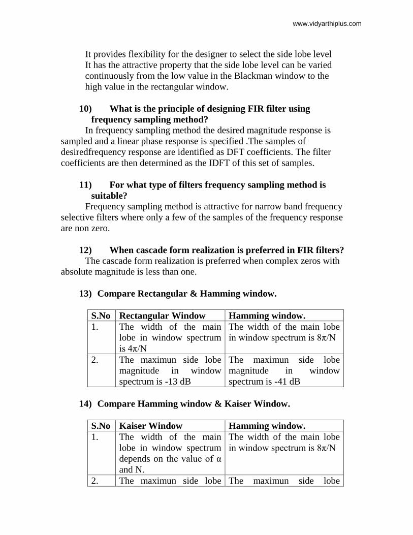
13) Compare Rectangular & Hamming window.
S.No Rectangular Window Hamming window.
1. The width of the main
lobe in window spectrum
is 4π/N
The width of the main lobe
in window spectrum is 8π/N
2. The maximun side lobe
magnitude in window
spectrum is -13 dB
The maximun side lobe
magnitude in window
spectrum is -41 dB
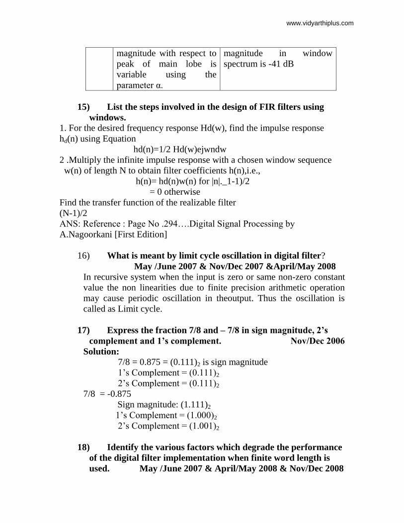
14) Compare Hamming window & Kaiser Window.
S.No Kaiser Window Hamming window.
1. The width of the main
lobe in window spectrum
depends on the value of α
and N.
The width of the main lobe
in window spectrum is 8π/N
2. The maximun side lobe The maximun side lobe
www.vidyarthiplus.com
magnitude with respect to
peak of main lobe is
variable using the
parameter α.
magnitude in window
spectrum is -41 dB
15) List the steps involved in the design of FIR filters using
windows.
1. For the desired frequency response Hd(w), find the impulse response
hd(n) using Equation
hd(n)=1/2 Hd(w)ejwndw
2 .Multiply the infinite impulse response with a chosen window sequence
w(n) of length N to obtain filter coefficients h(n),i.e.,
h(n)= hd(n)w(n) for |n|._1-1)/2
= 0 otherwise
Find the transfer function of the realizable filter
(N-1)/2
ANS: Reference : Page No .294….Digital Signal Processing by
A.Nagoorkani [First Edition]
16) What is meant by limit cycle oscillation in digital filter?
May /June 2007 & Nov/Dec 2007 &April/May 2008
In recursive system when the input is zero or same non-zero constant
value the non linearities due to finite precision arithmetic operation
may cause periodic oscillation in theoutput. Thus the oscillation is
called as Limit cycle.
17) Express the fraction 7/8 and – 7/8 in sign magnitude, 2’s
complement and 1’s complement. Nov/Dec 2006
Solution:
7/8 = 0.875 = (0.111)2 is sign magnitude
1’s Complement = (0.111)2
2’s Complement = (0.111)2
7/8 = -0.875
Sign magnitude: (1.111)2
1’s Complement = (1.000)2
2’s Complement = (1.001)2
18) Identify the various factors which degrade the performance
of the digital filter implementation when finite word length is
used. May /June 2007 & April/May 2008 & Nov/Dec 2008
www.vidyarthiplus.com
Input quantization error
Coefficient quantization error
Product quantization error
19) a) What are the quantization errors due to finite word
length register in digital filter.
b) What are the different quantization methods? Nov/Dec 2006
Quantization Error :
Input quantization error
Coefficient quantization error
Product quantization error
Quantization methods
Truncation
Rounding
20) Express the fraction (-7/32) in signed magnitude and 2’s
complement notations using 6 bits. Nov/Dec 2007 &Nov/Dec
2008
In Signed Magnitude: 1.001110
In 2’s complement: 1.110010
PART-B
1. a) Design a high pass filter hamming window by taking 9
samples of w(n) and with a cutoff frequency of 1.2 radians/sec
Nov/Dec 2006
Ans: Ref: Pg.No: 298-301, DSP by Nagoorkani.
2. a) Describe the design of FIR filter using frequency sampling
technique.
b) The desired frequency response of a low pass filter is given by
Hd(ω) ={ e –j2ω
; -π/4 ≤ ω ≤ π/4
0 ; other wise.
3. Obtain the filter coefficient, h(n) using RECTANGUAR window
define by W(n) = { 1; 0 ≤ n ≤ 4
0; otherwise.
www.vidyarthiplus.com
Nov/Dec 2007
Ans: a) Ref Pg.No 389-391, DSP by Salivahanan.
b) Ref Pg.No 399, DSP by Salivahanan.
4. ii) Determine the magnitude response of the FIR filter (M=11)
and show that phase and group delay are conatant.
iii) The desired frequency response of a low pass filter is given
by
Hd(ω) ={ e –j3ω
; -3π/4 ≤ ω ≤ 3π/4
0 ; other wise.
Determine H(ejω
) for M= 7using HAMMING window.
Ans: a) i) Ref Pg.No 437-439, DSP by Salivahanan.
ii) Ref Pg.No 383-384, DSP by Salivahanan.
iii) Ref Pg.No 400-401, DSP by Salivahanan.
iv) Ref Pg.No 426, DSP by Salivahanan.
5. Explain the design of lowpass digital butterworth filter.
ANS: Reference : Page No.347….Digital Signal Processing by
A.Nagoorkani [First Edition]
6. Explain the design of lowpass digital Chebyshev filter.
ANS: Reference : Page No.351….Digital Signal Processing by
A.Nagoorkani [First Edition]
7. Derive the frequency response of linear phase FIR filter when
impulse response is Symmetric when N is ODD.
ANS: Reference : Page No.264….Digital Signal Processing by
A.Nagoorkani [First Edition]
8. Derive the frequency response of linear phase FIR filter when
impulse response is Symmetric when N is EVEN.
ANS: Reference : Page No.267….Digital Signal Processing by
A.Nagoorkani [First Edition]
9. Derive the frequency response of linear phase FIR filter when
impulse response is Anti symmetric when N is ODD.
www.vidyarthiplus.com
ANS: Reference : Page No.269….Digital Signal Processing by
A.Nagoorkani [First Edition]
10. Derive the frequency response of linear phase FIR filter when
impulse response is Antisymmetric when N is EVEN.
ANS: Reference : Page No.272….Digital Signal Processing by
A.Nagoorkani [First Edition]
11. Analyze the Windows specifying the FIR filters
a. Rectangular window
b. Hamming window
c. Hanning window
d. Bartlett window
e. Kaiser window
ANS: Reference : Page No .281….Digital Signal Processing by
A.Nagoorkani [First Edition]
12. Draw the structures of FIR filters
Reference : Page No 502Digital Signal Processing by John G.Proakis[Third
Edition]
13. .Explain the design of FIR filters by frequency sampling
technique.
ANS: Reference : Page No.306….Digital Signal Processing by
A.Nagoorkani [First Edition]
14. a)i) Explain the characteristics of a Limit cycle oscillation w.r.t
the
system described by the difference equation
y(n) = 0.95y(n-1)+x(n).Determine the dead band of the filter.
ii) Draw the product quantisation noise model of second order
IIR fihter. Nov/Dec 2006 & Nov/Dec 2007
Ans: a) i) Dead band = [+0.625.-0.625 ]
ii) Ref Pg.No 513-514, DSP by Salivahanan.
15. For the given transfer function H(Z) = H1(Z) .H2(Z) ,where 1 1
H1(Z) = and H2(Z) =
1 – 0.5 Z-1
1 – 0.6 Z-1
www.vidyarthiplus.com
Find the output round off noise power. Nov/Dec 2006
Ans: 2-2b
/12(5.4315)
16. a)i) Consider the truncation of negative fraction number
represented in(β+1) bit fixed point binary form including sign bit
. Let (β-b) bits be truncated .Obtain the range of truncation errors
for signed magnitude ,2’s complement and 1’s complement
representation of negative numbers. Nov/Dec 2007
ii) The coefficients of a system defined by
1
H(Z) =
(1-0.4Z-1
)(1-0.55Z-1
)
are represented in anumber with a sign bit and 3 data bits.
iii) Consider the (b+1) bit bipolar A/D converter.Obtain an
expression for signal to quantization noise ratio . May /June 2007& Nov/Dec 2007&April/May2008 & Nov/Dec 2008
Ans: a) i) Ref Pg.No 496-499, DSP by Salivahanan.
ii) Direct form: 1/ [1-0.875z-1
+0.125Z-2
]
Cascade form:1/[1-0.375Z-1
][1-0.5Z-1
]
17. With the neat diagram explain the operation of limit cycle
oscillations.
Ref Pg.No 513-514, DSP by Salivahanan.
UNIT V - APPLICATIONS
PART-A
1. Define multirate digital signal processing.
The process of converting a signal from a given rate to a
different rate is called sampling rate conversion. The system that employs
multiple sampling rates in the processing of digital signals are called
digital signal processing systems.
2. Give the advantages of multirate digital signal processing.
Computational requirements are less
Storage for filter coefficients is less
Finite arithmetic effects are less
Sensitivity to filter coefficients lengths are less
www.vidyarthiplus.com
3. Give the applications of multirate digital signal processing.
Communication systems
Speech and audio processing systems
Antenna systems
Radar systems
4. Define Decimation.
The process of reducing the sampling rate of the signal is called
decimation (sampling rate compression).
5. Define Interpolation
The process of increasing the sampling rate of the signal is
called interpolation (sampling rate Expansion).
PART-B 1. Explain briefly: Multi rate signal processing May/June 2007
Ref Pg.No 751, DSP by Proakis
2. Explain briefly: Vocoder May/June 2007 Ref Pg.No 754, DSP by Proakis
3. Explain decimation of sampling rate by an integer factor D and
derive spectra for decimated signal May/June 2006
Ref Pg.No 755, DSP by Proakis
4. Explain interpolation of sampling rate by an integer factor I and
derive spectra for decimated signal May/June 2006
Ref Pg.No 760, DSP by Proakis
5. Explain about adaptive filters
Ref Pg.No 880, DSP by Proakis
www.vidyarthiplus.com