jeppiaar engineering collegejeppiaarcollege.org/jeppiaar/wp-content/uploads/2018/07/... ·...
TRANSCRIPT

JEPPIAAR ENGINEERING COLLEGE Jeppiaar Nagar, Rajiv Gandhi Salai – 600 119
DEPARTMENT OFMECHANICAL ENGINEERING
QUESTION BANK
V SEMESTER
ME6503 – Design of Machine Elements
Regulation – 2013

JEPPIAAR ENGINEERING COLLEGE
Vision of Institution
To build Jeppiaar Engineering College as an institution of academic excellence in
technological and management education to become a world class university.
Mission of Institution
To excel in teaching and learning, research and innovation by promoting the
principles of scientific analysis and creative thinking.
To participate in the production, development and dissemination of knowledge and
interact with national and international communities.
To equip students with values, ethics and life skills needed to enrich their lives and
enable them to meaningfully contribute to the progress of society.
To prepare students for higher studies and lifelong learning, enrich them with the
practical and entrepreneurial skills necessary to excel as future professionals and
contribute to Nation’s economy.
PO1 Engineering knowledge: Apply the knowledge of mathematics, science, engineering fundamentals, and
an engineering specialization to the solution of complex engineering problems.
PO2 Problem analysis: Identify, formulate, review research literature, and analyze complex engineering
problems reaching substantiated conclusions using first principles of mathematics, natural sciences, and
engineering sciences.
PO3 Design/development of solutions: Design solutions for complex engineering problems and design
system components or processes that meet the specified needs with appropriate consideration for the
public health and safety, and the cultural, societal, and environmental considerations
PO4 Conduct investigations of complex problems: Use research-based knowledge and research methods
including design of experiments, analysis and interpretation of data, and synthesis of the information to
provide valid conclusions.
PO5 Modern tool usage: Create, select, and apply appropriate techniques, resources, and modern
engineering and IT tools including prediction and modeling to complex engineering activities with an
understanding of the limitations.
PO6 The engineer and society: Apply reasoning informed by the contextual knowledge to assess societal,
health, safety, legal and cultural issues and the consequent responsibilities relevant to the professional
engineering practice.
PO7 Environment and sustainability: Understand the impact of the professional engineering solutions in
societal and environmental contexts, and demonstrate the knowledge of, and need for sustainable
development.
PO8 Ethics: Apply ethical principles and commit to professional ethics and responsibilities and norms of the
engineering practice.
PO9 Individual and team work: Function effectively as an individual, and as a member or leader in diverse
teams, and in multidisciplinary settings.
PO10 Communication: Communicate effectively on complex engineering activities with the engineering
community and with society at large, such as, being able to comprehend and write effective reports and
design documentation, make effective presentations, and give and receive clear instructions.
PO11 Project management and finance: Demonstrate knowledge and understanding of the engineering and
management principles and apply these to one’s own work, as a member and leader in a team, to
manage projects and in multidisciplinary environments.
PO12 Life-long learning: Recognize the need for, and have the preparation and ability to engage in
independent and life-long learning in the broadest context of technological change.

JEPPIAAR ENGINEERING COLLEGE
DEPARTMENT OF MECHANICAL ENGINEERING
Vision of the Department
To create excellent professionals in the field of Mechanical Engineering and to uplift the quality of
technical education on par with the International Standards.
Department Mission
1. To reinforce the fundamentals of Science and Mathematics to Mechanical Engineering and
critically and relatively investigate complex mechanical systems and processes.
2. To engage in the production, expansion and practice of advanced engineering applications
through knowledge sharing activities by interacting with global communities and industries.
3. Toequip students with engineering ethics, professional roles, corporate social
responsibility and life skills and apply them for the betterment of society.
4. To promote higher studies and lifelong learning and entrepreneurial skills and develop
excellent professionals for empowering nation’s economy.
PEO’s
1. To enrich the technical knowledge of design, manufacturing and management of mechanical
systems and develop creative and analytical thinking in research.
2. To relate, strengthen and develop the theoretical knowledge of the Mechanical Engineering
by exhibiting various concepts applied through diverse industrial exposures and experts’
guidance.
3. Facilitate the students to communicate effectively on complex social, professional and
engineering activities with strict adherence to ethical principles.
4. Create awareness for independent and life long learning and develop the ability to keep
abreast of modern trends and adopt them for personal technological growth of the
nation.
PSO’s
1. To understand the basic concept of various mechanical engineering field such as design,
manufacturing, thermal and industrial engineering.
2. To apply the knowledge in advanced mechanical system and processes by using design and
analysis techniques.
3. To develop student’s professional skills to meet the industry requirements and entrepreneurial
skills for improving nation’s economy stronger.

ME6503- PRINCIPLES OF MANAGEMENT
COURSE OUTCOMES
C303.1 Explain the design process and stresses due to different loading in machine
members.
C303.2 Design shafts, keys and couplings based on strength, rigidity and critical speed.
C303.3 Design various joints for structures under different loading conditions and discuss
the bonded joints.
C303.4 Classify the springs and design springs, flywheels, crank shafts and connecting
rods.
C303.5 Classify the bearings, design journal bearings and select rolling contact bearings.

ME6503 DESIGN OF MACHINE ELEMENTS L T P C 3 0 0 3
OBJECTIVES
• To familiarize the various steps involved in the Design Process
•To understand the principles involved in evaluating the shape and dimensions of a component to satisfy functional and strength requirements.
• To learn to use standard practices and standard data
• To learn to use catalogues and standard machine components
(Use of P S G Design Data Book is permitted)
UNIT I STEADY STRESSES AND VARIABLE STRESSES IN MACHINE MEMBERS 10
Introduction to the design process - factors influencing machine design, selection of materials
based on mechanical properties - Preferred numbers, fits and tolerances – Direct, Bending
and torsional stress equations – Impact and shock loading – calculation of principle stresses
for various load combinations, eccentric loading – curved beams – crane hook and ‘C’ frame-
Factor of safety theories of failure – Design based on strength and stiffness – stress
concentration – Design for variable loading.
UNIT II SHAFTS AND COUPLINGS 8
Design of solid and hollow shafts based on strength, rigidity and critical speed – Keys,
keyways and splines - Rigid and flexible couplings.
UNIT III TEMPORARY AND PERMANENT JOINTS 9
Threaded fastners - Bolted joints including eccentric loading, Knuckle joints, Cotter joints –
Welded joints, riveted joints for structures - theory of bonded joints.
UNIT IV ENERGY STORING ELEMENTS AND ENGINE COMPONENTS9
Various types of springs, optimization of helical springs - rubber springs - Flywheels
considering stresses in rims and arms for engines and punching machines- Connecting Rods
and crank shafts.
UNIT V BEARINGS 9 Sliding contact and rolling contact bearings - Hydrodynamic journal bearings, Sommerfeld
Number, Raimondi and Boyd graphs, -- Selection of Rolling Contact bearings.
TOTAL: 45 PERIODS
OUTCOMES:
components
TEXT BOOK:
1. BhandariV,“Design of Machine Elements”,3rd
Edition, Tata McGraw-Hill Book Co, 2010.
2. Joseph Shigley, Charles Mischke, Richard Budynas and Keith Nisbett “Mechanical
Engineering Design”, 8th
Edition, Tata McGraw-Hill, 2008.
REFERENCES:
1. Sundararajamoorthy T. V. Shanmugam .N, “Machine Design”, Anuradha Publications,
Chennai, 2003.
2. Robert C. Juvinall and Kurt M. Marshek,“Fundamentals of Machine Design”,4 Edition,
Wiley, 2005.
3. Alfred Hall, Halowenko, A and Laughlin, H., “Machine Design”, Tata McGraw-Hill
BookCo.(Schaum’s Outline), 2010
4. Bernard Hamrock, Steven Schmid,Bo Jacobson, “Fundamentals of Machine Elements”,2
Edition, Tata McGraw-Hill Book Co., 2006.
5. Orthwein W, “Machine Component Design”, Jaico Publishing Co, 2003.
6. AnselUgural, “Mechanical Design – An Integral Approach", 1st Edition, Tata McGraw-Hill
Book Co, 2003.
7. Merhyle F. Spotts, Terry E. Shoup and Lee E. Hornberger, “Design of Machine Elements”
8th Edition, Printice Hall, 2003.
JEPPIAAR ENGINEERING COLLEGE Jeppiaar Nagar, Rajiv Gandhi Salai – 600 119
DEPARTMENT OFMECHANICAL ENGINEERING
QUESTION BANK
Subject : ME6503 – Design of Machine Elements Year / Sem : III / V
UNIT I STEADY STRESSES AND VARIABLE STRESSES IN MACHINE
MEMBERS
Introduction to the design process - factors influencing machine design, selection of materials based on mechanical
properties - Preferred numbers, fits and tolerances – Direct, Bending and torsional stress equations – Impact and
shock loading – calculation of principle stresses for various load combinations, eccentric loading – curved beams –
crane hook and ‘C’ frame- Factor of safety theories of failure – Design based on strength and stiffness – stress
concentration – Design for variable loading.
PART-A
CO Mapping : C304.1
Q.No. Questions BT
Level Competence PO
1 Define design. What are the various phases of design
process? How the machine design may be classified?
BTL-1
BTL-2
Remembering
Understanding PO1
2 What is Adaptive design? Where is it used? Give
examples. BTL-1 Remembering PO1
3 What do you mean by Optimum design? What are the
various optimization methods available? BTL-1 Remembering PO1
4 What are the factors that govern selection of materials
while designing a machine component? BTL-1 Remembering
PO1,PO6,
PO7
5 What are the common materials used in mechanical
engineering design? BTL-1 Remembering PO1
6 Describe material properties hardness, stiffness and
resilience. BTL-1 Remembering PO1
7 Define modulus of resilience and proof resilience. BTL-1 Remembering PO1
8 Differentiate hardness and toughness. BTL-2 Understanding PO1
9 Define factor of safety. BTL-1 Remembering PO1

10 List the important factors that influence the magnitude of
factor of safety. BTL-1 Remembering PO4,PO6,
PO7,PO8
11 What are the different types of loads that can act on
machine components? BTL-1 Remembering PO1
12 What is an impact load? Give examples. BTL-1 Remembering PO1
13 What are the modes of fracture? Explain Griffith theory.
(Or) State the condition for crack growth. BTL-1 Remembering PO1
14 What are the types of fracture? Distinguish them. BTL-1 Remembering PO1
15 What are the various theories of failure? BTL-1 Remembering PO1
16
What is the use of Goodman &Soderberg diagrams? Write
Soderberg equation for machine component subjected to
(a) combination of mean and variable torques (b)
combination of mean and variable bending moments.
BTL-1 Remembering PO1
17 Which theory of failure is suitable for the design of brittle
materials? BTL-1 Remembering PO1
18 What is curved beam? Give some example for curved
beam. BTL-1 Remembering PO1
19 State the difference between straight beams and curved
beams.
BTL-1 Remembering PO1
20 Why nonsymmetrical I and T sections are preferred in
design of curved beams? BTL-1 Remembering PO1
21 Define principal plane and principal stresses? BTL-1 Remembering PO1
22 Why normal stress theory is not suitable for ductile
materials? BTL-1 Remembering PO1
23 Define stress concentration and stress concentration factor. BTL-1 Remembering PO1
24 State the various methods of finding stresses concentration
factors. BTL-1 Remembering PO1
25 Give some methods of reducing stress concentration. BTL-1 Remembering PO1
26
Explain notch sensitivity. State the relation between stress
concentration factor, fatigue stress concentration factor and
notch sensitivity.
BTL-1 Remembering PO1
27 What are the factors that affect notch sensitivity? BTL-1 Remembering PO1
28 What are the types of variable stresses? BTL-1 Remembering PO1
29 Differentiate between repeated stress and reversed stress. BTL-2 Understanding PO1
30 Explain size factor in endurance strength. BTL-2 Understanding PO1
31 Define fatigue. What are the methods used to improve
fatigue strength? BTL-1 Remembering PO1
32 What is an S-N curve? What is low and high cycle fatigue? BTL-1 Remembering PO1,PO2
PART-B & PART-C
Q.No. Questions BT
Level Competence PO

1
A Circular bar of 500 mm length is supported freely at it
two ends. It is acted upon by a central concentrated cyclic
load having a minimum value of 20 kN and a maximum
value of 50 kN. Determine the diameter of bar by taking a
factor of safety 1.5, size effect of 0.85, surface finish factor
of 0.9. The material properties of bar as given by: ultimate
strength of 650 MPa, yield strength of 500 MPa and
endurance strength of 350 MPa.
BTL-5 Evaluating PO1,PO2,
PO3
2
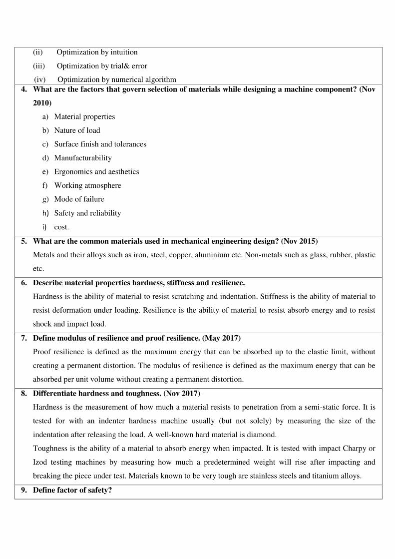
A hollow circular column of external diameter 250 mm
and internal diameter 200 mm carries a projecting bracket
on which a load of 20 kN rests, as shown in Fig. The
centre of the load from the centre of the column is 500
mm. Find the stresses at the sides of the column. All
dimensions in mm.
BTL-5 Evaluating PO1
3
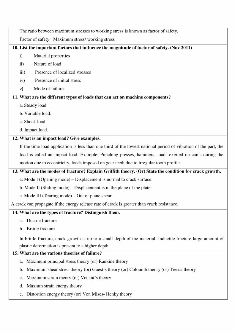
(i) Theframeofapunchpressisshowninfigure
below.Findthestressesattheinnerand outersurfaceat section
X-X ofthe frame, ifW=5000 N.
ii) What is factor of safety? List the factors to be
considered while deciding the factor of safety.
BTL-5
BTL-2
Evaluating
Understanding
PO1,
PO4,PO6,
PO7,PO8
4 (i) What are the factors influencing machine design?
Explain it.
BTL-
1BTL-2
Remembering
Understanding PO1
(ii)Write short notes on the following: (a)
Interchangeability (b) Tolerance (c) Allowance.
5
An unknown weights fall through 10 mm onto a collar
which is rigidly attached to the lower end of a vertical bar
3 m long and 600 mm2 cross section. The maximum
instantaneous extension is 2 mm. What is the
corresponding stress and the value of the weight? Take E =
200 kN/mm2.
BTL-5 Evaluating PO1
6
A mass of 50 kg drops through 25 mm at the center of a
250 mm long simply supported beam. The beam has a
square cross section. It is made of steel 30C8 (Syt = 400
N/mm2) and the factor of safety is 2. The modulus of
elasticity is 207000 N/mm2. Determine the dimension of
the cross section of the beam.
BTL-5 Evaluating PO1,PO2,
PO3
7
A shaft of diameter ‘d’ is subjected to a torque varying
between 900 Nm to 1800 Nm. Assuming a factor of safety
2 and a stress concentration factor of 1.2, find the diameter
of the shaft. Take u= 650 N/mm2, y= 480 N/mm
2, Size
factor B = 0.85 and surface finish factor C = 0.5.
BTL-5 Evaluating PO1,PO2,
PO3
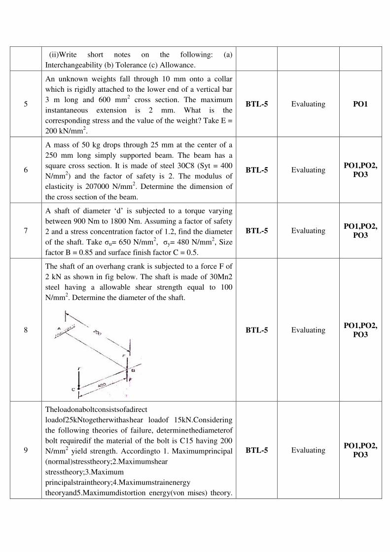
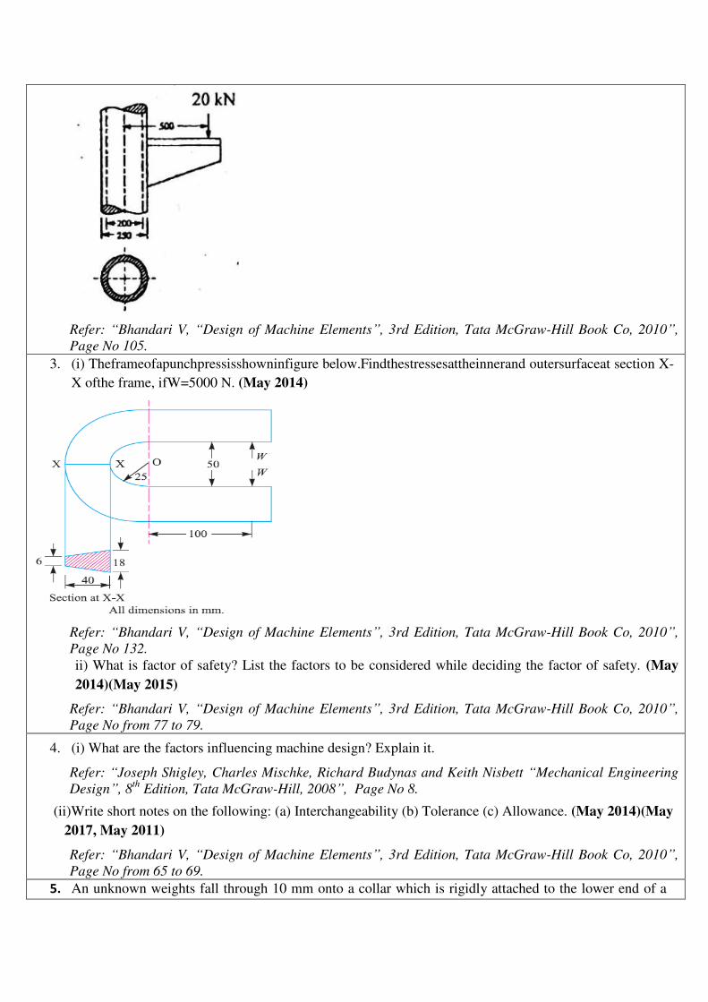
8
The shaft of an overhang crank is subjected to a force F of
2 kN as shown in fig below. The shaft is made of 30Mn2
steel having a allowable shear strength equal to 100
N/mm2. Determine the diameter of the shaft.
BTL-5 Evaluating PO1,PO2,
PO3
9
Theloadonaboltconsistsofadirect
loadof25kNtogetherwithashear loadof 15kN.Considering
the following theories of failure, determinethediameterof
bolt requiredif the material of the bolt is C15 having 200
N/mm2 yield strength. Accordingto 1. Maximumprincipal
(normal)stresstheory;2.Maximumshear
stresstheory;3.Maximum
principalstraintheory;4.Maximumstrainenergy
theoryand5.Maximumdistortion energy(von mises) theory.
BTL-5 Evaluating PO1,PO2,
PO3
Assume F.O.S = 2.
10
A solid circular shaft of diameter 45 mm is loaded by
bending moment 650 Nm, torque 900 Nm and axial tensile
force of 30 kN. The shaft material is ductile with yield
strength of 280 MPa. Determine the factor of safety
according to Maximum principle stress, Tresca and Von
misses theories of failure.
BTL-5 Evaluating PO1,PO3,
PO5
11
A cantilever rod of length 120 mm with circular section is
subjected to a cyclic transverse load; varying from -100 N
and 300 N at its free end. Determine the diameter ‘d’ of the
rod, by (i) Goodman method and (ii) Soderberg method
using the following data. Factor of safety = 2; Theoretical
stress concentration factor = 1.4; Notch sensitivity factor =
0.9; Ultimate strength = 550 MPa; Yield strength = 320
MPa; Endurance limit = 275 MPa; Size correction factor =
0.85; Surface correction factor = 0.9
BTL-5 Evaluating PO1,PO2,
PO3
12
A machine component is subjected to a flexural stress
which fluctuates between + 300 MN/m2 and – 150 MN/m
2.
Determine the value of minimum ultimate strength
according to i) Gerber relation ii) Modified Goodman
relation and iii) Soderberg relation. Take yield strength =
0.55 Ultimate strength; Endurance strength = 0.5 Ultimate
strength; and factor of safety = 2.
BTL-5 Evaluating PO1
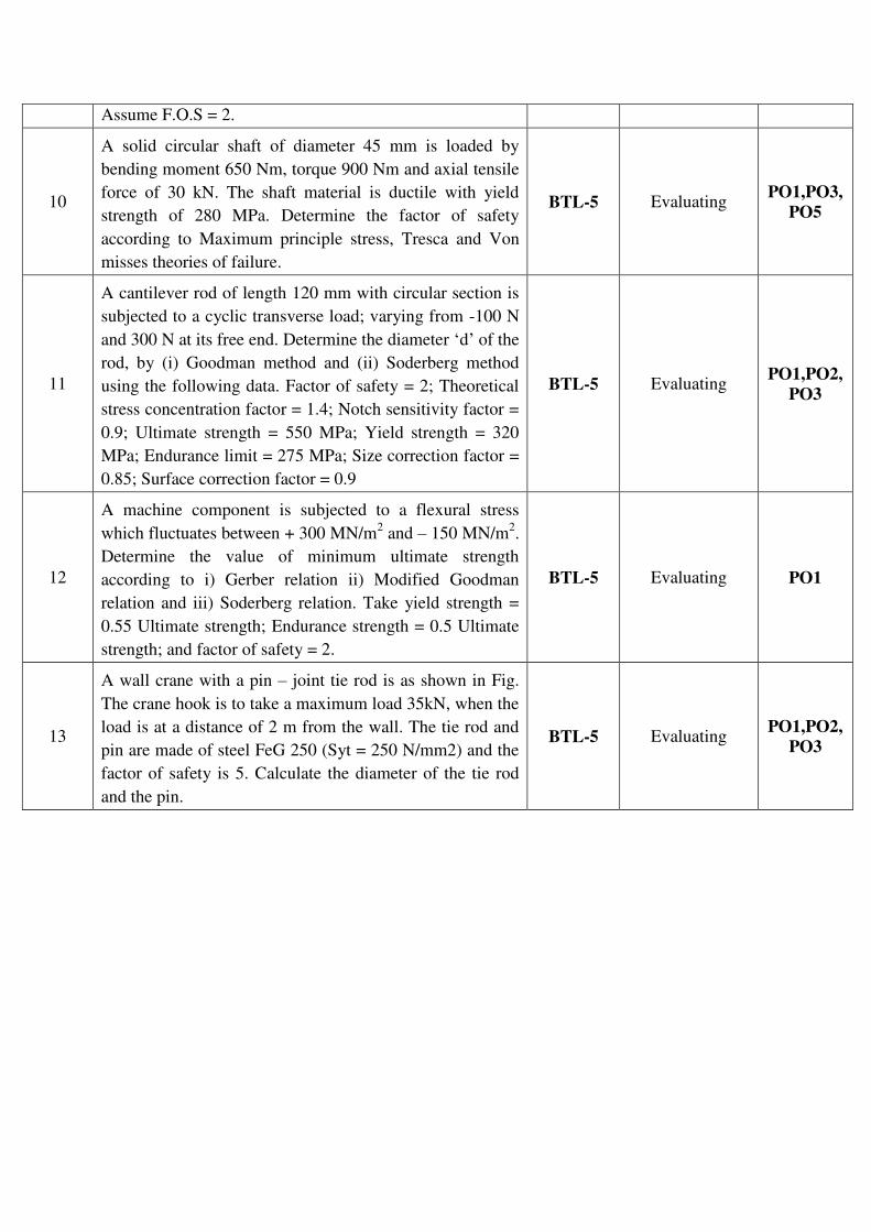
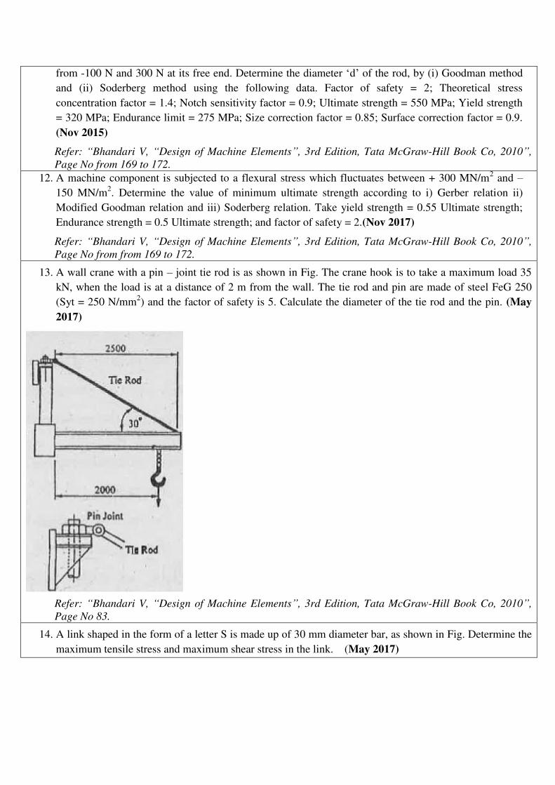
13
A wall crane with a pin – joint tie rod is as shown in Fig.
The crane hook is to take a maximum load 35kN, when the
load is at a distance of 2 m from the wall. The tie rod and
pin are made of steel FeG 250 (Syt = 250 N/mm2) and the
factor of safety is 5. Calculate the diameter of the tie rod
and the pin.
BTL-5 Evaluating PO1,PO2,
PO3
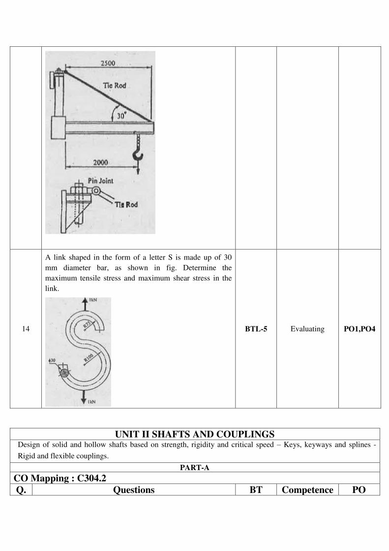
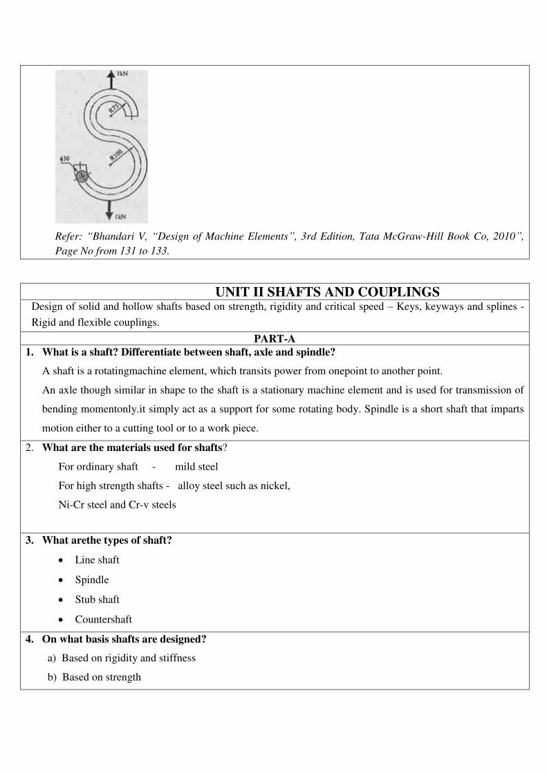
14
A link shaped in the form of a letter S is made up of 30
mm diameter bar, as shown in fig. Determine the
maximum tensile stress and maximum shear stress in the
link.
BTL-5 Evaluating PO1,PO4
UNIT II SHAFTS AND COUPLINGS Design of solid and hollow shafts based on strength, rigidity and critical speed – Keys, keyways and splines -
Rigid and flexible couplings.
PART-A
CO Mapping : C304.2
Q. Questions BT Competence PO
No. Level
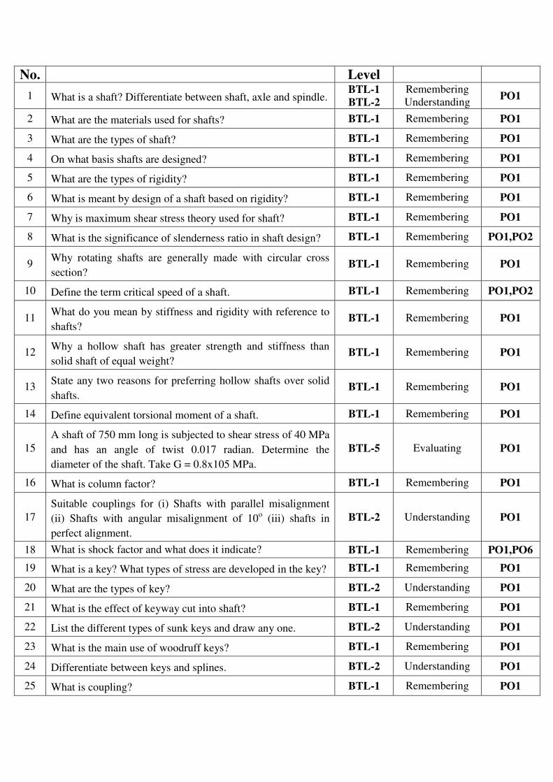
1 What is a shaft? Differentiate between shaft, axle and spindle. BTL-1
BTL-2
Remembering
Understanding PO1
2 What are the materials used for shafts? BTL-1 Remembering PO1
3 What are the types of shaft? BTL-1 Remembering PO1
4 On what basis shafts are designed? BTL-1 Remembering PO1
5 What are the types of rigidity? BTL-1 Remembering PO1
6 What is meant by design of a shaft based on rigidity? BTL-1 Remembering PO1
7 Why is maximum shear stress theory used for shaft? BTL-1 Remembering PO1
8 What is the significance of slenderness ratio in shaft design? BTL-1 Remembering PO1,PO2
9 Why rotating shafts are generally made with circular cross
section? BTL-1 Remembering PO1
10 Define the term critical speed of a shaft. BTL-1 Remembering PO1,PO2
11 What do you mean by stiffness and rigidity with reference to
shafts? BTL-1 Remembering PO1
12 Why a hollow shaft has greater strength and stiffness than
solid shaft of equal weight? BTL-1 Remembering PO1
13 State any two reasons for preferring hollow shafts over solid
shafts. BTL-1 Remembering PO1
14 Define equivalent torsional moment of a shaft. BTL-1 Remembering PO1
15
A shaft of 750 mm long is subjected to shear stress of 40 MPa
and has an angle of twist 0.017 radian. Determine the
diameter of the shaft. Take G = 0.8x10⁵ MPa.
BTL-5 Evaluating PO1
16 What is column factor? BTL-1 Remembering PO1
17
Suitable couplings for (i) Shafts with parallel misalignment
(ii) Shafts with angular misalignment of 10o (iii) shafts in
perfect alignment.
BTL-2 Understanding PO1
18 What is shock factor and what does it indicate? BTL-1 Remembering PO1,PO6
19 What is a key? What types of stress are developed in the key? BTL-1 Remembering PO1
20 What are the types of key? BTL-2 Understanding PO1
21 What is the effect of keyway cut into shaft? BTL-1 Remembering PO1
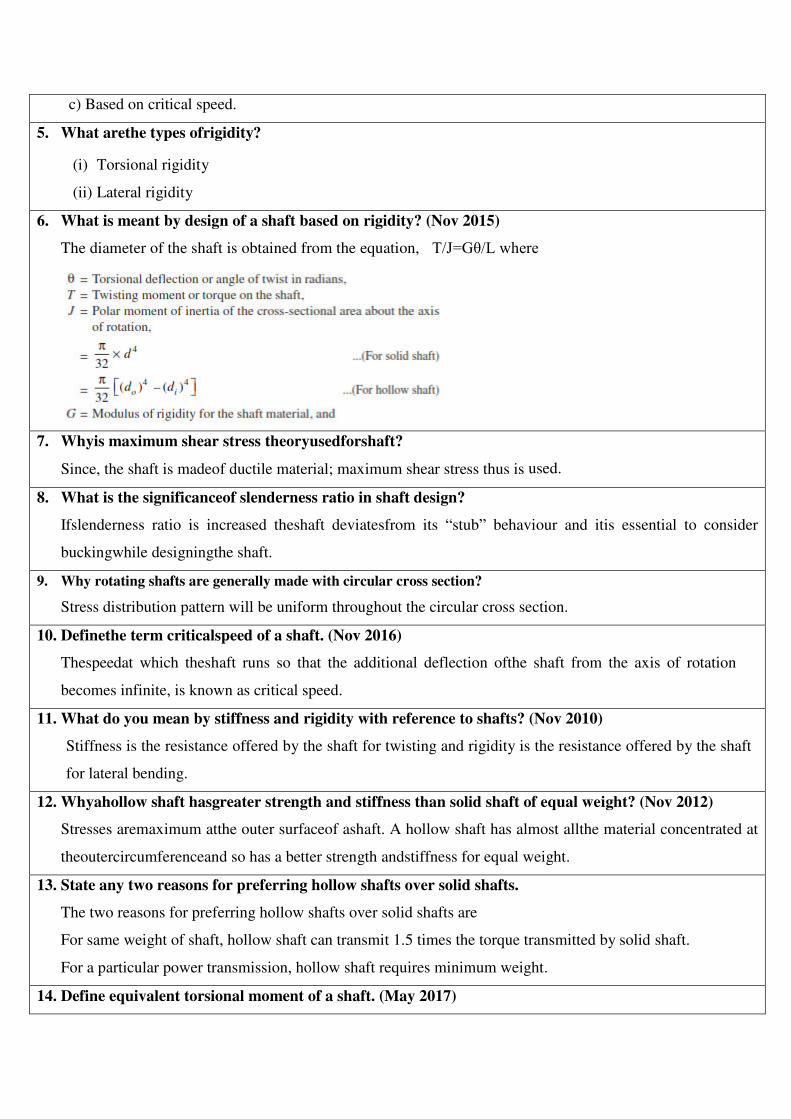
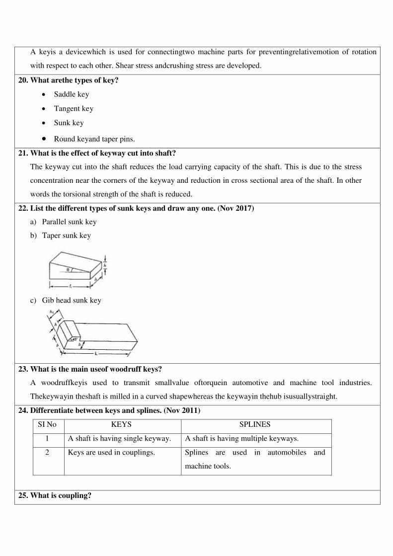
22 List the different types of sunk keys and draw any one. BTL-2 Understanding PO1
23 What is the main use of woodruff keys? BTL-1 Remembering PO1
24 Differentiate between keys and splines. BTL-2 Understanding PO1
25 What is coupling? BTL-1 Remembering PO1

26 What are the purposes in machinery for which couplings are
used? BTL-1 Remembering PO1
27 State the reasons for which the couplings are located near the
bearings. BTL-1 Remembering PO1
28 Under what circumstances flexible couplings are used? BTL-1 Remembering PO1
29 Where are flexible couplings used? BTL-1 Remembering PO1
30 What are the possible modes of failure of the pin (bolt) in a
flexible coupling? BTL-1 Remembering PO1
31 What is the advantage of gear coupling? BTL-1 Remembering PO1
32 What is a flange coupling? What are the different types of
flange coupling? BTL-1 Remembering PO1
33 What is the difference between rigid and flexible coupling? BTL-2 Understanding PO1
34 Differentiate between a cotter joint and a knuckle joint. BTL-2 Understanding PO1
PART-B & PART-C
Q.
No. Questions
BT
Level Competence PO
1
In an axial flow rotary compressor, the shaft is subjected to
maximum twisting moment and maximum bending moment
of 1500 Nm and 300 Nm respectively. Neglecting the axial
load, determine the diameter, if the permissible shear stress is
50 N/mm2. Assume minor shocks. If the shaft is hollow one
with K = di/do = 0.4., what will be material saving in hollow
shaft which is subjected to same loading and material as a
solid shaft.
BTL-5 Evaluating PO1,PO2,
PO3,PO6
2
A hollow shaft of 0.5 m outside diameter and 0.3 m inside
diameter is used to drive a propeller of a marine vessel. The
shaft is mounted on bearings 6 metre apart and it transmits
5600 kW at 150 rpm. The maximum axial propeller thrust is
500 kN and the shaft weighs 70 kN. Determine (i) The
maximum shear stress developed in the shaft and (ii) The
angular twist between the bearings.
BTL-5 Evaluating PO1
3
Ahollow shaft is required to transmit 600 kW at 110 rpm, the
maximum torque being 20% greater than the mean. The shear
stress is not to exceed 63 MPa and twist in a length of 3
meters not to exceed 1.4 degrees. Find the external diameter
of the shaft, if the internal diameter to the external diameter is
3/8. Take modulus of rigidity as 84 GPa.
BTL-5 Evaluating PO1,PO2,
PO3
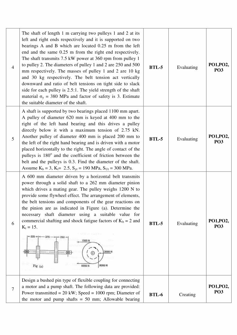
4
The shaft of length 1 m carrying two pulleys 1 and 2 at its
left and right ends respectively and it is supported on two
bearings A and B which are located 0.25 m from the left
end and the same 0.25 m from the right end respectively.
The shaft transmits 7.5 kW power at 360 rpm from pulley 1
to pulley 2. The diameters of pulley 1 and 2 are 250 and 500
mm respectively. The masses of pulley 1 and 2 are 10 kg
and 30 kg respectively. The belt tension act vertically
downward and ratio of belt tensions on tight side to slack
side for each pulley is 2.5:1. The yield strength of the shaft
material y = 380 MPa and factor of safety is 3. Estimate
the suitable diameter of the shaft.
BTL-5 Evaluating PO1,PO2,
PO3
5
A shaft is supported by two bearings placed 1100 mm apart.
A pulley of diameter 620 mm is keyed at 400 mm to the
right of the left hand bearing and this drives a pulley
directly below it with a maximum tension of 2.75 kN.
Another pulley of diameter 400 mm is placed 200 mm to
the left of the right hand bearing and is driven with a motor
placed horizontally to the right. The angle of contact of the
pulleys is 180o and the coefficient of friction between the
belt and the pulleys is 0.3. Find the diameter of the shaft.
Assume Kb = 3, Kt= 2.5, Syt = 190 MPa, SUt = 300 MPa.
BTL-5 Evaluating PO1,PO2,
PO3
6
A 600 mm diameter driven by a horizontal belt transmits
power through a solid shaft to a 262 mm diameter pinion
which drives a mating gear. The pulley weighs 1200 N to
provide some flywheel effect. The arrangement of elements,
the belt tensions and components of the gear reactions on
the pinion are as indicated in Figure (a). Determine the
necessary shaft diameter using a suitable value for
commercial shafting and shock fatigue factors of Kb = 2 and
Kt = 15.
BTL-5 Evaluating PO1,PO2,
PO3
7
Design a bushed pin type of flexible coupling for connecting
a motor and a pump shaft. The following data are provided:
Power transmitted = 20 kW; Speed = 1000 rpm; Diameter of
the motor and pump shafts = 50 mm; Allowable bearing
BTL-6
Creating
PO1,PO2,
PO3
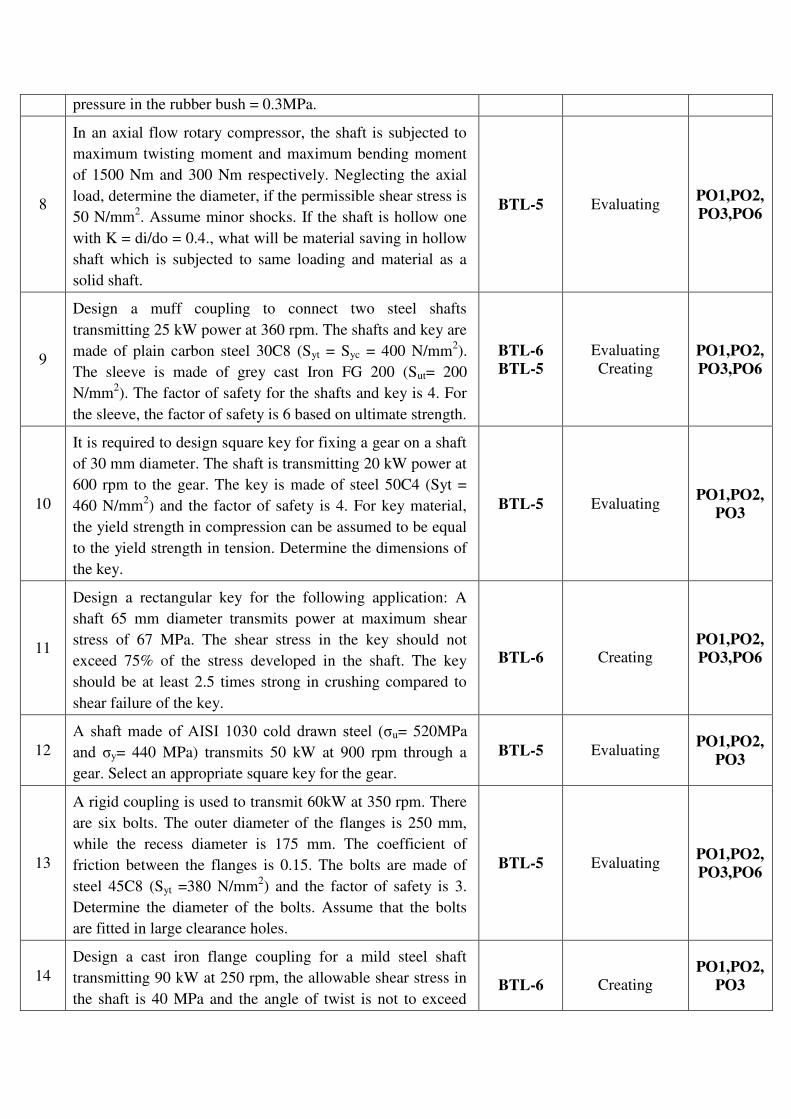
pressure in the rubber bush = 0.3MPa.
8
In an axial flow rotary compressor, the shaft is subjected to
maximum twisting moment and maximum bending moment
of 1500 Nm and 300 Nm respectively. Neglecting the axial
load, determine the diameter, if the permissible shear stress is
50 N/mm2. Assume minor shocks. If the shaft is hollow one
with K = di/do = 0.4., what will be material saving in hollow
shaft which is subjected to same loading and material as a
solid shaft.
BTL-5 Evaluating PO1,PO2,
PO3,PO6
9
Design a muff coupling to connect two steel shafts
transmitting 25 kW power at 360 rpm. The shafts and key are
made of plain carbon steel 30C8 (Syt = Syc = 400 N/mm2).
The sleeve is made of grey cast Iron FG 200 (Sut= 200
N/mm2). The factor of safety for the shafts and key is 4. For
the sleeve, the factor of safety is 6 based on ultimate strength.
BTL-6
BTL-5
Evaluating
Creating PO1,PO2,
PO3,PO6
10
It is required to design square key for fixing a gear on a shaft
of 30 mm diameter. The shaft is transmitting 20 kW power at
600 rpm to the gear. The key is made of steel 50C4 (Syt =
460 N/mm2) and the factor of safety is 4. For key material,
the yield strength in compression can be assumed to be equal
to the yield strength in tension. Determine the dimensions of
the key.
BTL-5 Evaluating PO1,PO2,
PO3
11
Design a rectangular key for the following application: A
shaft 65 mm diameter transmits power at maximum shear
stress of 67 MPa. The shear stress in the key should not
exceed 75% of the stress developed in the shaft. The key
should be at least 2.5 times strong in crushing compared to
shear failure of the key.
BTL-6
Creating PO1,PO2,
PO3,PO6
12
A shaft made of AISI 1030 cold drawn steel ( u= 520MPa
and y= 440 MPa) transmits 50 kW at 900 rpm through a
gear. Select an appropriate square key for the gear.
BTL-5 Evaluating PO1,PO2,
PO3
13
A rigid coupling is used to transmit 60kW at 350 rpm. There
are six bolts. The outer diameter of the flanges is 250 mm,
while the recess diameter is 175 mm. The coefficient of
friction between the flanges is 0.15. The bolts are made of
steel 45C8 (Syt =380 N/mm2) and the factor of safety is 3.
Determine the diameter of the bolts. Assume that the bolts
are fitted in large clearance holes.
BTL-5 Evaluating PO1,PO2,
PO3,PO6
14
Design a cast iron flange coupling for a mild steel shaft
transmitting 90 kW at 250 rpm, the allowable shear stress in
the shaft is 40 MPa and the angle of twist is not to exceed
BTL-6
Creating PO1,PO2,
PO3
1oin a length of 20 meters. The allowable shear stress in the
coupling bolt is 30 MPa. Take G = 84 kN/mm2.
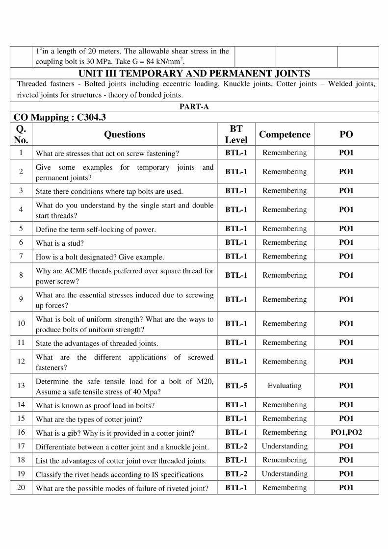
UNIT III TEMPORARY AND PERMANENT JOINTS Threaded fastners - Bolted joints including eccentric loading, Knuckle joints, Cotter joints – Welded joints,
riveted joints for structures - theory of bonded joints.
PART-A
CO Mapping : C304.3
Q.
No. Questions
BT
Level Competence PO
1 What are stresses that act on screw fastening? BTL-1 Remembering PO1
2 Give some examples for temporary joints and
permanent joints? BTL-1 Remembering PO1
3 State there conditions where tap bolts are used. BTL-1 Remembering PO1
4 What do you understand by the single start and double
start threads? BTL-1 Remembering PO1
5 Define the term self-locking of power. BTL-1 Remembering PO1
6 What is a stud? BTL-1 Remembering PO1
7 How is a bolt designated? Give example. BTL-1 Remembering PO1
8 Why are ACME threads preferred over square thread for
power screw? BTL-1 Remembering PO1
9 What are the essential stresses induced due to screwing
up forces? BTL-1 Remembering PO1
10 What is bolt of uniform strength? What are the ways to
produce bolts of uniform strength? BTL-1 Remembering PO1
11 State the advantages of threaded joints. BTL-1 Remembering PO1
12 What are the different applications of screwed
fasteners? BTL-1 Remembering PO1
13 Determine the safe tensile load for a bolt of M20,
Assume a safe tensile stress of 40 Mpa? BTL-5 Evaluating PO1
14 What is known as proof load in bolts? BTL-1 Remembering PO1
15 What are the types of cotter joint? BTL-1 Remembering PO1
16 What is a gib? Why is it provided in a cotter joint? BTL-1 Remembering PO1,PO2
17 Differentiate between a cotter joint and a knuckle joint. BTL-2 Understanding PO1
18 List the advantages of cotter joint over threaded joints. BTL-1 Remembering PO1
19 Classify the rivet heads according to IS specifications BTL-2 Understanding PO1
20 What are the possible modes of failure of riveted joint? BTL-1 Remembering PO1
21 What is a rivet? What are the different working
processes used for making riveting? BTL-1 Remembering PO1
22 Name the possible modes of failure of riveting joint. BTL-1 Remembering PO1,PO6
23 Define welding. Why are welded joints preferred over
riveted joints? BTL-1 Remembering PO1
24 What are the types of welded joints? BTL-2 Understanding PO1
25 Define butt and lap joint? BTL-1 Remembering PO1
26 What is the total shear in a double strap butt joint with
equal length of straps? BTL-1 Remembering PO1
27 Define Tee joint and corner joint. BTL-1 Remembering PO1
28 When will the edge preparation need? BTL-1 Remembering PO1
29
What is the minimum size for fillet weld? If the required
weld size from strength consideration is too small how
will you fulfill the condition of minimum weld size?
BTL-1 Remembering PO1
30 Why throat is considered while calculating stresses in
fillet welds? BTL-1 Remembering PO1
31 When will the weld deposit be weaker? BTL-1 Remembering PO1
32
What is the bending stress induced in a weld when a
circular rod of diameter d, welded to a rigid plate by a
circular fillet weld of size ‘t’, which is subjected to a
bending moment M?
BTL-1 Remembering PO1
33 State the two types of eccentric welded connections. BTL-2 Understanding PO1
34 Define circumferential joint. BTL-1 Remembering PO1
35 State the disadvantages of welded joints? BTL-1 Remembering PO1
PART-B & PART-C
Q.
No.
Questions BT
Level
Competence PO
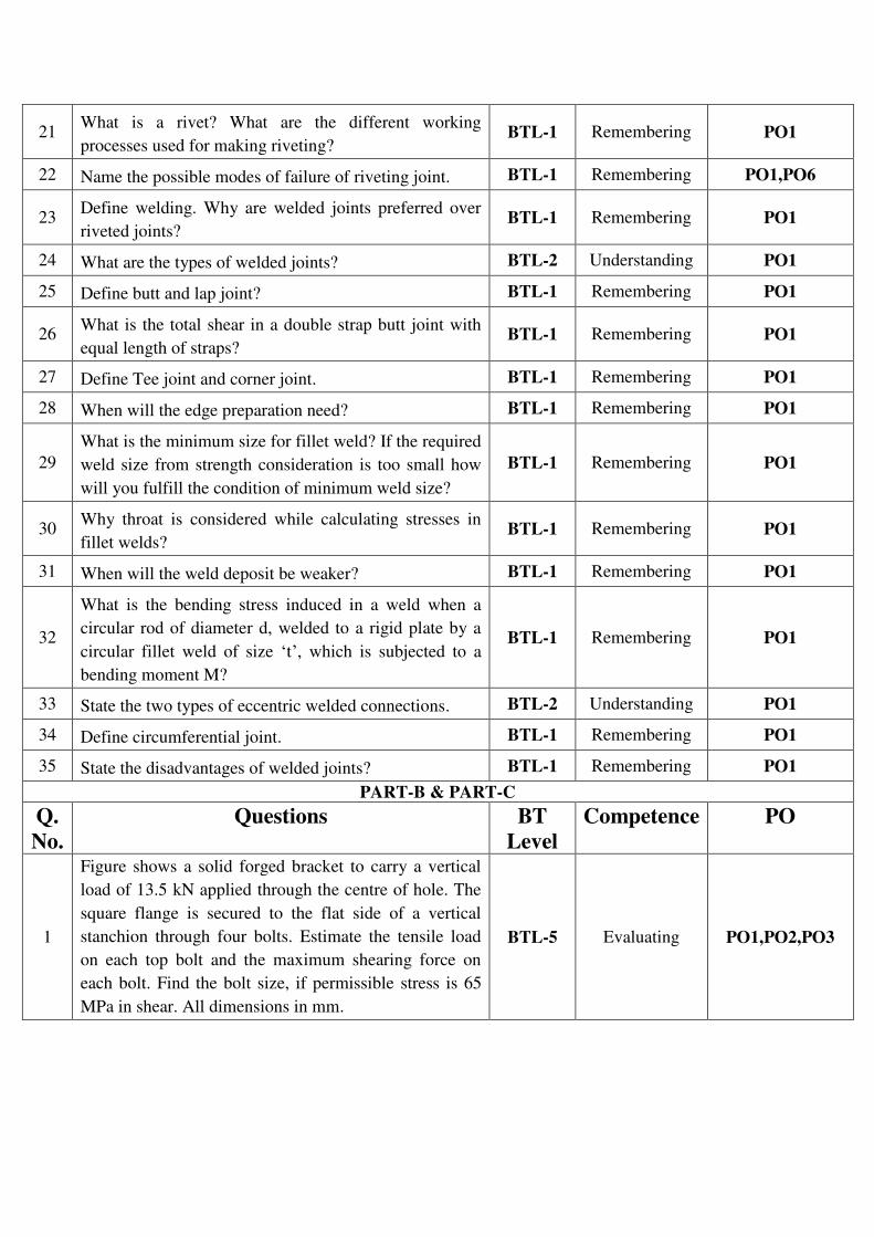
1
Figure shows a solid forged bracket to carry a vertical
load of 13.5 kN applied through the centre of hole. The
square flange is secured to the flat side of a vertical
stanchion through four bolts. Estimate the tensile load
on each top bolt and the maximum shearing force on
each bolt. Find the bolt size, if permissible stress is 65
MPa in shear. All dimensions in mm.
BTL-5 Evaluating PO1,PO2,PO3

2
A steel bolt of M16x2 is 300 mm long carries an impact
load of 500 Nm. If the threads stop adjacent to the Nut
and E = 2.1 x 10⁵MPa. (i) Find the stress in the root
area (ii) Find the stress if the shank area is reduced to
root area.
BTL-5 Evaluating PO1
3
A steam engine cylinder of 30 mm effective diameter is
subjected to a steam pressure of 1.5 MPa. The cylinder
head is connected by means of 8 bolts having yield
strength of 30 MPa and endurance limit of 240 MPa.
The bolts are tightened with an initial preload of 1.5
times that of steam load. A soft copper gasket is used to
make the joint leak proof assuming a fatigue stress
concentration factor of 1.4, and factor of safety of 2;
determine the size of the bolts required.
BTL-5
Evaluating
PO1,PO2,PO3,P
O6
4
A steel plate is subjected to a force of 5 kN and fixed to
a channel by means of three identical bolts as shown in
Fig. The bolts are made of from 50C8 steel (Syt = 380
N/mm2) and the factor of safety is 3. Specify the size of
the bolts.
BTL-6
Creating PO1,PO2,PO3,P
O6
5
Fig shows a bracket fixed on a steel column by means of
3 bolts of same size. If the permissible tensile and shear
stress are limited to 75 N/mm2 and 55 N/mm
2
respectively. Find the size of bolts.
BTL-6
Creating PO1,PO2,PO3

6
Design a knuckle joint to withstand a load of 100 kN.
All the parts of the joint are made of the same material
of the same material with ut= uc= 480 MPa, and u=
360 MPa. Use factor of safety of 6 on Ultimate strength.
BTL-6
Creating PO1,PO2,PO3,P
O6
7
It is required to design a knuckle joint to connect two
circular rods subjected to an axial tensile force of 50 kN.
The rods are co-axial and a small amount of angular
movement between their axes is permissible. Design the
joint and specify the dimensions of its components.
Select suitable materials for the parts. Assume rod
materials as 30C8 and FOS = 5.
BTL-6
Creating PO1,PO2,PO3,P
O6
8
Design a double riveted butt joint with two cover plates
for the longitudinal steam of a boiler shell 1.5 m in
diameter subjected to a steam pressure of 0.95 N/mm2.
Assume joint efficiency as 75%, allowable tensile stress
in the plate 90 MPa; compressive stress140 MPa and
shear stress in the rivet 56 MPa.
BTL-6
Creating
PO1,PO2,PO3
9
A welded connection, as shown below is subjected to an
eccentric force of 60 kN in the plane of welds.
Determine the size of the welds, if the permissible shear
stress for the weld is 90 N/mm2. Assume static
conditions.
BTL-5 Evaluating PO1,PO2,PO3
10
(i) A butt welded joint with ground and flush surface is
subjected to tensile load which varies from 50 kN to 100
kN. Plates are 10 mm thick. Determine the length of
BTL-5 Evaluating PO1,PO2,PO3
weld required for over 2,500,000 cycles.
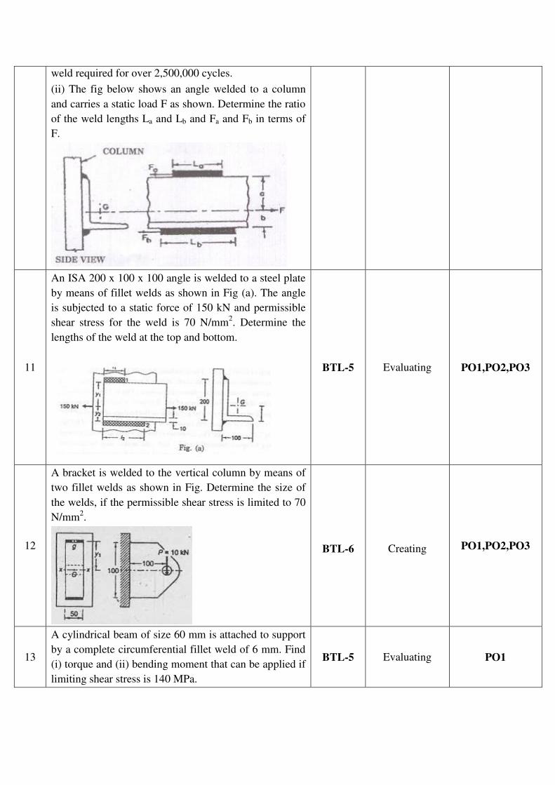
(ii) The fig below shows an angle welded to a column
and carries a static load F as shown. Determine the ratio
of the weld lengths La and Lb and Fa and Fb in terms of
F.
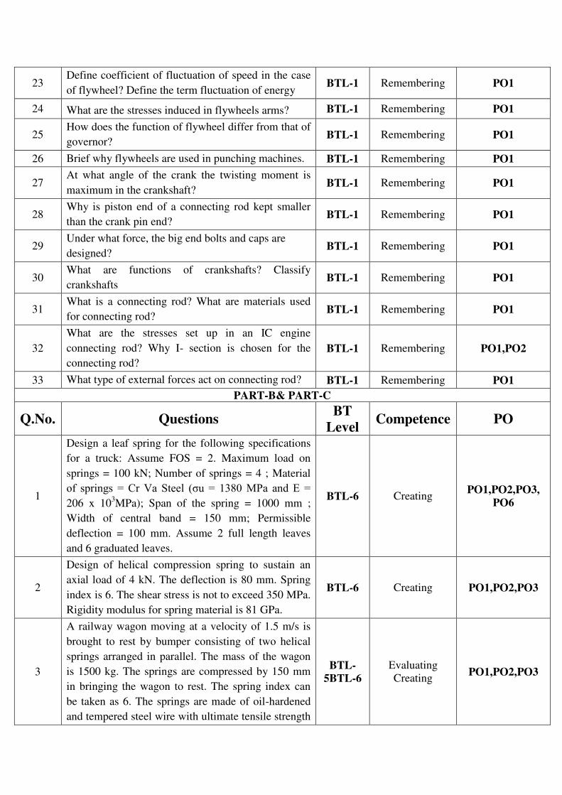
11
An ISA 200 x 100 x 100 angle is welded to a steel plate
by means of fillet welds as shown in Fig (a). The angle
is subjected to a static force of 150 kN and permissible
shear stress for the weld is 70 N/mm2. Determine the
lengths of the weld at the top and bottom.
BTL-5 Evaluating PO1,PO2,PO3
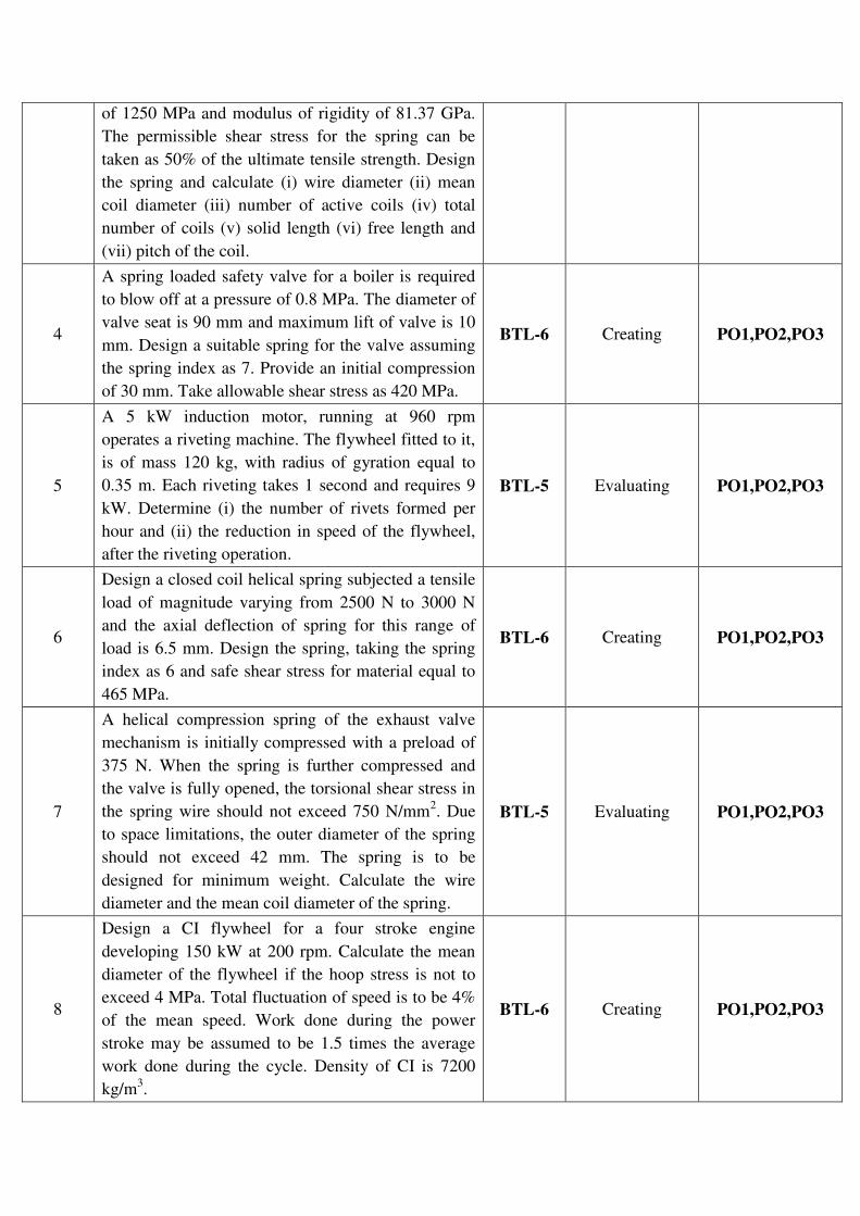
12
A bracket is welded to the vertical column by means of
two fillet welds as shown in Fig. Determine the size of
the welds, if the permissible shear stress is limited to 70
N/mm2.
BTL-6
Creating PO1,PO2,PO3
13
A cylindrical beam of size 60 mm is attached to support
by a complete circumferential fillet weld of 6 mm. Find
(i) torque and (ii) bending moment that can be applied if
limiting shear stress is 140 MPa.
BTL-5 Evaluating PO1

UNIT IV ENERGY STORING ELEMENTS AND ENGINE COMPONENTS Various types of springs, optimization of helical springs - rubber springs - Flywheels considering stresses in rims
and arms for engines and punching machines- Connecting Rods and crank shafts. PART-A
CO Mapping : C304.4
Q.No. Questions BT
Level Competence PO
1 What is spring and where it is employed? BTL-1 Remembering PO1
2 By what materials the springs can be made? BTL-1 Remembering PO1
3 Define (a) spring index (b) spring rate. BTL-1 Remembering PO1
4 Write the formula for natural frequency of spring. BTL-1 Remembering PO1
5 What is the effect of increase in wire diameter on the
allowable stress value? BTL-1 Remembering PO1
6 State any two function of springs. BTL-1 Remembering PO1
7 What are the various types of springs? BTL-1 Remembering PO1
8
How will you find whether the given helical spring is
a compression spring or tension spring? (or)
Distinguish between close coiled and open coiled
springs.
BTL-1
BTL-2
Remembering
Understanding PO1
9 What are conical springs? BTL-1 Remembering PO1
10 What are the purposes of composite springs? BTL-1 Remembering PO1
11 What are torsion springs? BTL-1 Remembering PO1
12 How the stiffness of the spring can be increased? BTL-1 Remembering PO1
13 What are the advantages of leaf springs over helical
springs? BTL-1 Remembering PO1
14 Sketch the stresses induced in the cross section of a
helical spring, considering Wahl’s effect. BTL-1 Remembering PO1
15 While designing helical springs, K is introduced in
the shear stress equation, why? BTL-1 Remembering PO1
16 What are active coils? BTL-1 Remembering PO1
17 What are the end conditions of the spring? BTL-1 Remembering PO1
18 What is fly wheel? What is the application of
flywheel? BTL-1 Remembering PO1
19 What type of stresses is produced in a disc flywheel? BTL-1 Remembering PO1
20 What is the main function of a flywheel in an engine? BTL-1 Remembering PO1
21 State any two type of flywheel. BTL-2 Understanding PO1
22 What is flywheel effect? BTL-1 Remembering PO1
23 Define coefficient of fluctuation of speed in the case
of flywheel? Define the term fluctuation of energy BTL-1 Remembering PO1
24 What are the stresses induced in flywheels arms? BTL-1 Remembering PO1
25 How does the function of flywheel differ from that of
governor? BTL-1 Remembering PO1
26 Brief why flywheels are used in punching machines. BTL-1 Remembering PO1
27 At what angle of the crank the twisting moment is
maximum in the crankshaft? BTL-1 Remembering PO1
28 Why is piston end of a connecting rod kept smaller
than the crank pin end? BTL-1 Remembering PO1
29 Under what force, the big end bolts and caps are
designed? BTL-1 Remembering PO1
30 What are functions of crankshafts? Classify
crankshafts BTL-1 Remembering PO1
31 What is a connecting rod? What are materials used
for connecting rod? BTL-1 Remembering PO1
32
What are the stresses set up in an IC engine
connecting rod? Why I- section is chosen for the
connecting rod?
BTL-1 Remembering PO1,PO2
33 What type of external forces act on connecting rod? BTL-1 Remembering PO1
PART-B& PART-C
Q.No. Questions BT
Level Competence PO
1
Design a leaf spring for the following specifications
for a truck: Assume FOS = 2. Maximum load on
springs = 100 kN; Number of springs = 4 ; Material
of springs = Cr Va Steel ( u = 1380 MPa and E =
206 x 103MPa); Span of the spring = 1000 mm ;
Width of central band = 150 mm; Permissible
deflection = 100 mm. Assume 2 full length leaves
and 6 graduated leaves.
BTL-6 Creating PO1,PO2,PO3,
PO6
2
Design of helical compression spring to sustain an
axial load of 4 kN. The deflection is 80 mm. Spring
index is 6. The shear stress is not to exceed 350 MPa.
Rigidity modulus for spring material is 81 GPa.
BTL-6 Creating PO1,PO2,PO3
3
A railway wagon moving at a velocity of 1.5 m/s is
brought to rest by bumper consisting of two helical
springs arranged in parallel. The mass of the wagon
is 1500 kg. The springs are compressed by 150 mm
in bringing the wagon to rest. The spring index can
be taken as 6. The springs are made of oil-hardened
and tempered steel wire with ultimate tensile strength
BTL-
5BTL-6
Evaluating
Creating PO1,PO2,PO3
of 1250 MPa and modulus of rigidity of 81.37 GPa.
The permissible shear stress for the spring can be
taken as 50% of the ultimate tensile strength. Design
the spring and calculate (i) wire diameter (ii) mean
coil diameter (iii) number of active coils (iv) total
number of coils (v) solid length (vi) free length and
(vii) pitch of the coil.
4
A spring loaded safety valve for a boiler is required
to blow off at a pressure of 0.8 MPa. The diameter of
valve seat is 90 mm and maximum lift of valve is 10
mm. Design a suitable spring for the valve assuming
the spring index as 7. Provide an initial compression
of 30 mm. Take allowable shear stress as 420 MPa.
BTL-6 Creating PO1,PO2,PO3
5
A 5 kW induction motor, running at 960 rpm
operates a riveting machine. The flywheel fitted to it,
is of mass 120 kg, with radius of gyration equal to
0.35 m. Each riveting takes 1 second and requires 9
kW. Determine (i) the number of rivets formed per
hour and (ii) the reduction in speed of the flywheel,
after the riveting operation.
BTL-5 Evaluating PO1,PO2,PO3
6
Design a closed coil helical spring subjected a tensile
load of magnitude varying from 2500 N to 3000 N
and the axial deflection of spring for this range of
load is 6.5 mm. Design the spring, taking the spring
index as 6 and safe shear stress for material equal to
465 MPa.
BTL-6 Creating PO1,PO2,PO3
7
A helical compression spring of the exhaust valve
mechanism is initially compressed with a preload of
375 N. When the spring is further compressed and
the valve is fully opened, the torsional shear stress in
the spring wire should not exceed 750 N/mm2. Due
to space limitations, the outer diameter of the spring
should not exceed 42 mm. The spring is to be
designed for minimum weight. Calculate the wire
diameter and the mean coil diameter of the spring.
BTL-5 Evaluating PO1,PO2,PO3
8
Design a CI flywheel for a four stroke engine
developing 150 kW at 200 rpm. Calculate the mean
diameter of the flywheel if the hoop stress is not to
exceed 4 MPa. Total fluctuation of speed is to be 4%
of the mean speed. Work done during the power
stroke may be assumed to be 1.5 times the average
work done during the cycle. Density of CI is 7200
kg/m3.
BTL-6 Creating PO1,PO2,PO3
9
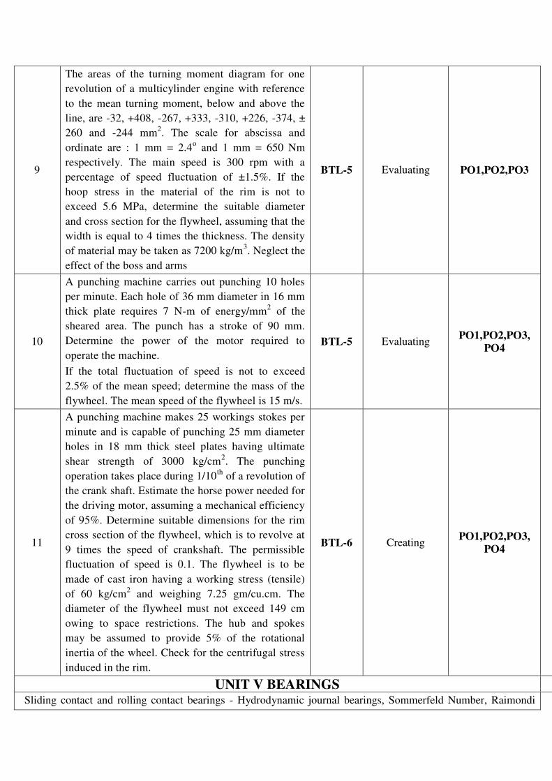
The areas of the turning moment diagram for one
revolution of a multicylinder engine with reference
to the mean turning moment, below and above the
line, are -32, +408, -267, +333, -310, +226, -374, ±
260 and -244 mm2. The scale for abscissa and
ordinate are : 1 mm = 2.4o and 1 mm = 650 Nm
respectively. The main speed is 300 rpm with a
percentage of speed fluctuation of ±1.5%. If the
hoop stress in the material of the rim is not to
exceed 5.6 MPa, determine the suitable diameter
and cross section for the flywheel, assuming that the
width is equal to 4 times the thickness. The density
of material may be taken as 7200 kg/m3. Neglect the
effect of the boss and arms
BTL-5 Evaluating PO1,PO2,PO3
10
A punching machine carries out punching 10 holes
per minute. Each hole of 36 mm diameter in 16 mm
thick plate requires 7 N-m of energy/mm2 of the
sheared area. The punch has a stroke of 90 mm.
Determine the power of the motor required to
operate the machine.
If the total fluctuation of speed is not to exceed
2.5% of the mean speed; determine the mass of the
flywheel. The mean speed of the flywheel is 15 m/s.
BTL-5 Evaluating PO1,PO2,PO3,
PO4
11
A punching machine makes 25 workings stokes per
minute and is capable of punching 25 mm diameter
holes in 18 mm thick steel plates having ultimate
shear strength of 3000 kg/cm2. The punching
operation takes place during 1/10th
of a revolution of
the crank shaft. Estimate the horse power needed for
the driving motor, assuming a mechanical efficiency
of 95%. Determine suitable dimensions for the rim
cross section of the flywheel, which is to revolve at
9 times the speed of crankshaft. The permissible
fluctuation of speed is 0.1. The flywheel is to be
made of cast iron having a working stress (tensile)
of 60 kg/cm2 and weighing 7.25 gm/cu.cm. The
diameter of the flywheel must not exceed 149 cm
owing to space restrictions. The hub and spokes
may be assumed to provide 5% of the rotational
inertia of the wheel. Check for the centrifugal stress
induced in the rim.
BTL-6 Creating PO1,PO2,PO3,
PO4
UNIT V BEARINGS
Sliding contact and rolling contact bearings - Hydrodynamic journal bearings, Sommerfeld Number, Raimondi
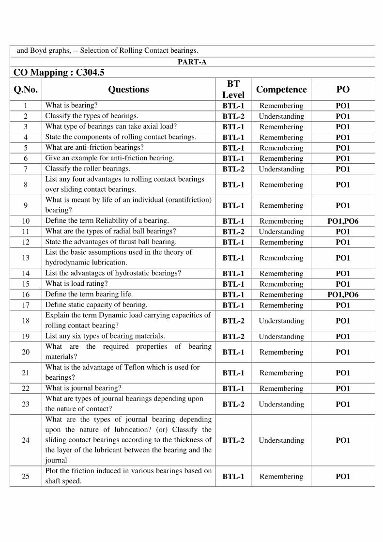
and Boyd graphs, -- Selection of Rolling Contact bearings.
PART-A
CO Mapping : C304.5
Q.No. Questions BT
Level Competence PO
1 What is bearing? BTL-1 Remembering PO1
2 Classify the types of bearings. BTL-2 Understanding PO1
3 What type of bearings can take axial load? BTL-1 Remembering PO1
4 State the components of rolling contact bearings. BTL-1 Remembering PO1
5 What are anti-friction bearings? BTL-1 Remembering PO1
6 Give an example for anti-friction bearing. BTL-1 Remembering PO1
7 Classify the roller bearings. BTL-2 Understanding PO1
8 List any four advantages to rolling contact bearings
over sliding contact bearings. BTL-1 Remembering PO1
9 What is meant by life of an individual (orantifriction)
bearing? BTL-1 Remembering PO1
10 Define the term Reliability of a bearing. BTL-1 Remembering PO1,PO6
11 What are the types of radial ball bearings? BTL-2 Understanding PO1
12 State the advantages of thrust ball bearing. BTL-1 Remembering PO1
13 List the basic assumptions used in the theory of
hydrodynamic lubrication. BTL-1 Remembering PO1
14 List the advantages of hydrostatic bearings? BTL-1 Remembering PO1
15 What is load rating? BTL-1 Remembering PO1
16 Define the term bearing life. BTL-1 Remembering PO1,PO6
17 Define static capacity of bearing. BTL-1 Remembering PO1
18 Explain the term Dynamic load carrying capacities of
rolling contact bearing? BTL-2 Understanding PO1
19 List any six types of bearing materials. BTL-2 Understanding PO1
20 What are the required properties of bearing
materials? BTL-1 Remembering PO1
21 What is the advantage of Teflon which is used for
bearings? BTL-1 Remembering PO1
22 What is journal bearing? BTL-1 Remembering PO1
23 What are types of journal bearings depending upon
the nature of contact? BTL-2 Understanding PO1
24
What are the types of journal bearing depending
upon the nature of lubrication? (or) Classify the
sliding contact bearings according to the thickness of
the layer of the lubricant between the bearing and the
journal
BTL-2 Understanding PO1
25 Plot the friction induced in various bearings based on
shaft speed. BTL-1 Remembering PO1
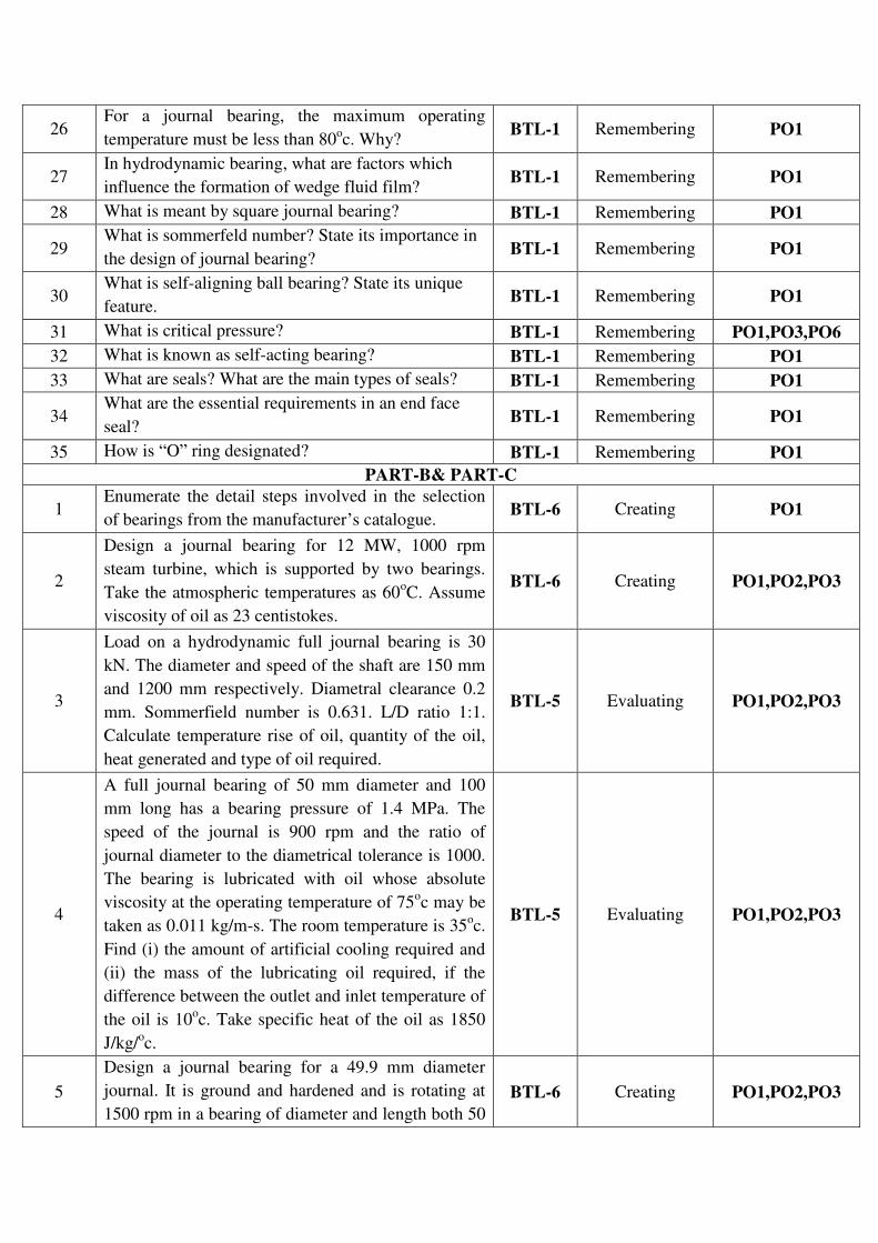
26 For a journal bearing, the maximum operating
temperature must be less than 80oc. Why?
BTL-1 Remembering PO1
27 In hydrodynamic bearing, what are factors which
influence the formation of wedge fluid film? BTL-1 Remembering PO1
28 What is meant by square journal bearing? BTL-1 Remembering PO1
29 What is sommerfeld number? State its importance in
the design of journal bearing? BTL-1 Remembering PO1
30 What is self-aligning ball bearing? State its unique
feature. BTL-1 Remembering PO1
31 What is critical pressure? BTL-1 Remembering PO1,PO3,PO6
32 What is known as self-acting bearing? BTL-1 Remembering PO1
33 What are seals? What are the main types of seals? BTL-1 Remembering PO1
34 What are the essential requirements in an end face
seal? BTL-1 Remembering PO1
35 How is “O” ring designated? BTL-1 Remembering PO1
PART-B& PART-C
1 Enumerate the detail steps involved in the selection
of bearings from the manufacturer’s catalogue. BTL-6 Creating PO1
2
Design a journal bearing for 12 MW, 1000 rpm
steam turbine, which is supported by two bearings.
Take the atmospheric temperatures as 60oC. Assume
viscosity of oil as 23 centistokes.
BTL-6 Creating PO1,PO2,PO3
3
Load on a hydrodynamic full journal bearing is 30
kN. The diameter and speed of the shaft are 150 mm
and 1200 mm respectively. Diametral clearance 0.2
mm. Sommerfield number is 0.631. L/D ratio 1:1.
Calculate temperature rise of oil, quantity of the oil,
heat generated and type of oil required.
BTL-5 Evaluating PO1,PO2,PO3
4
A full journal bearing of 50 mm diameter and 100
mm long has a bearing pressure of 1.4 MPa. The
speed of the journal is 900 rpm and the ratio of
journal diameter to the diametrical tolerance is 1000.
The bearing is lubricated with oil whose absolute
viscosity at the operating temperature of 75oc may be
taken as 0.011 kg/m-s. The room temperature is 35oc.
Find (i) the amount of artificial cooling required and
(ii) the mass of the lubricating oil required, if the
difference between the outlet and inlet temperature of
the oil is 10oc. Take specific heat of the oil as 1850
J/kg/oc.
BTL-5 Evaluating PO1,PO2,PO3
5
Design a journal bearing for a 49.9 mm diameter
journal. It is ground and hardened and is rotating at
1500 rpm in a bearing of diameter and length both 50
BTL-6 Creating PO1,PO2,PO3
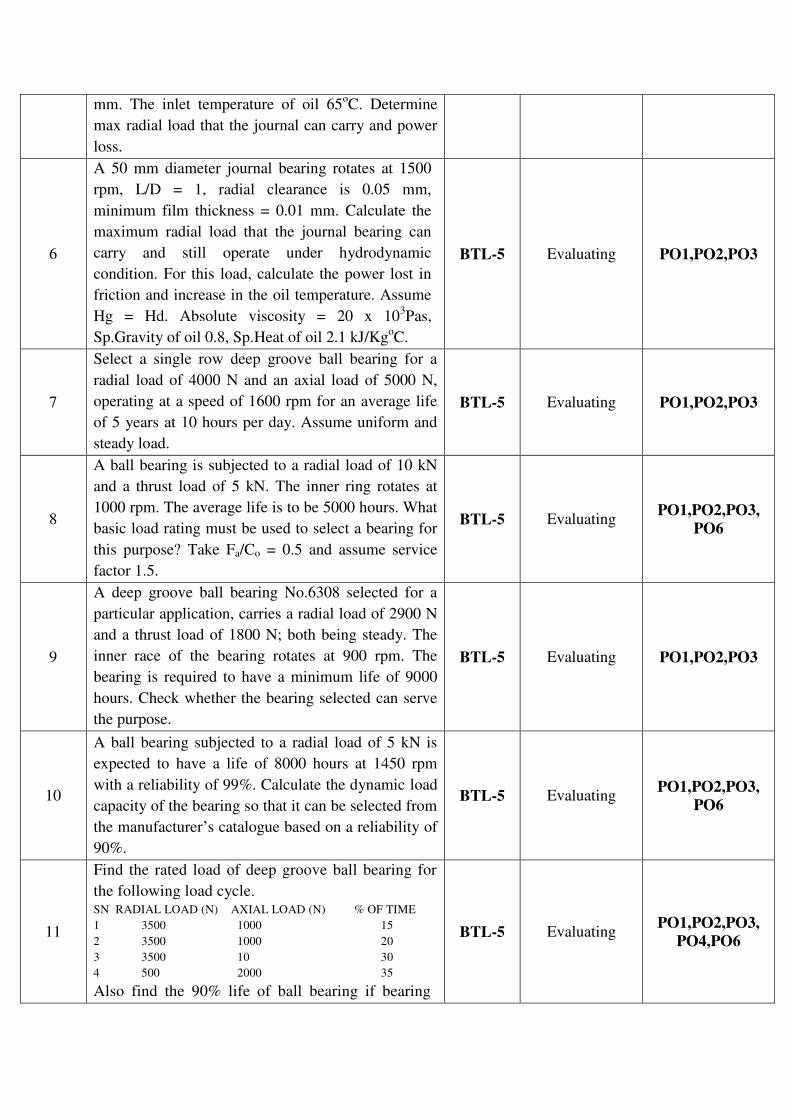
mm. The inlet temperature of oil 65oC. Determine
max radial load that the journal can carry and power
loss.
6
A 50 mm diameter journal bearing rotates at 1500
rpm, L/D = 1, radial clearance is 0.05 mm,
minimum film thickness = 0.01 mm. Calculate the
maximum radial load that the journal bearing can
carry and still operate under hydrodynamic
condition. For this load, calculate the power lost in
friction and increase in the oil temperature. Assume
Hg = Hd. Absolute viscosity = 20 x 103Pas,
Sp.Gravity of oil 0.8, Sp.Heat of oil 2.1 kJ/KgoC.
BTL-5 Evaluating PO1,PO2,PO3
7
Select a single row deep groove ball bearing for a
radial load of 4000 N and an axial load of 5000 N,
operating at a speed of 1600 rpm for an average life
of 5 years at 10 hours per day. Assume uniform and
steady load.
BTL-5 Evaluating PO1,PO2,PO3
8
A ball bearing is subjected to a radial load of 10 kN
and a thrust load of 5 kN. The inner ring rotates at
1000 rpm. The average life is to be 5000 hours. What
basic load rating must be used to select a bearing for
this purpose? Take Fa/Co = 0.5 and assume service
factor 1.5.
BTL-5 Evaluating PO1,PO2,PO3,
PO6
9
A deep groove ball bearing No.6308 selected for a
particular application, carries a radial load of 2900 N
and a thrust load of 1800 N; both being steady. The
inner race of the bearing rotates at 900 rpm. The
bearing is required to have a minimum life of 9000
hours. Check whether the bearing selected can serve
the purpose.
BTL-5 Evaluating PO1,PO2,PO3
10
A ball bearing subjected to a radial load of 5 kN is
expected to have a life of 8000 hours at 1450 rpm
with a reliability of 99%. Calculate the dynamic load
capacity of the bearing so that it can be selected from
the manufacturer’s catalogue based on a reliability of
90%.
BTL-5 Evaluating PO1,PO2,PO3,
PO6
11
Find the rated load of deep groove ball bearing for
the following load cycle. SN RADIAL LOAD (N) AXIAL LOAD (N) % OF TIME
1 3500 1000 15
2 3500 1000 20
3 3500 10 30
4 500 2000 35
Also find the 90% life of ball bearing if bearing
BTL-5 Evaluating PO1,PO2,PO3,
PO4,PO6

used is 6207 with dynamic capacity 19620 N.
UNIT I STEADY STRESSES AND VARIABLE STRESSES IN MACHINE
MEMBERS
Introduction to the design process - factors influencing machine design, selection of materials based on
mechanical properties - Preferred numbers, fits and tolerances – Direct, Bending and torsional stress equations –
Impact and shock loading – calculation of principle stresses for various load combinations, eccentric loading –
curved beams – crane hook and ‘C’ frame- Factor of safety theories of failure – Design based on strength and
stiffness – stress concentration – Design for variable loading.
PART-A 1. Define design. What are the various phases of design process? How the machine design may be
classified? (Nov 2016)
Design is a process of activities to gather all the information necessary to realize the designer’s idea as real
product. The steps involved in design process are: (i) Recognition of need (ii) Definition of problem (iii)
Synthesis (iv) Analysis and optimization (v) Evaluation (vi) Presentation.
Machine design is classified as
(i)Adaptive design
(ii) Development design
(iii) New design
a) Rational design
b) Empirical design
c) Industrial design
d) Optimum design
e) Element design
f) Computer aided design.
2. What is Adaptive design? Where is it used? Give examples. (Nov 2012)
It is a design process where a new product is developed just by making small changes to the existing
product. It is used where no or limited scope is available to go for an entirely new design. Examples: Die
design for a small sized product which is similar to an existing large sized product.
3. What do you mean by Optimum design? What are the various optimization methods available? (Nov
2011)
Optimization is the process of maximizing a desired quantity or minimizing an undesired one. The various
optimization methods are:
(i) Optimization by evaluation
(ii) Optimization by intuition
(iii) Optimization by trial& error
(iv) Optimization by numerical algorithm
4. What are the factors that govern selection of materials while designing a machine component? (Nov
2010)
a) Material properties
b) Nature of load
c) Surface finish and tolerances
d) Manufacturability
e) Ergonomics and aesthetics
f) Working atmosphere
g) Mode of failure
h) Safety and reliability
i) cost.
5. What are the common materials used in mechanical engineering design? (Nov 2015)
Metals and their alloys such as iron, steel, copper, aluminium etc. Non-metals such as glass, rubber, plastic
etc.
6. Describe material properties hardness, stiffness and resilience.
Hardness is the ability of material to resist scratching and indentation. Stiffness is the ability of material to
resist deformation under loading. Resilience is the ability of material to resist absorb energy and to resist
shock and impact load.
7. Define modulus of resilience and proof resilience. (May 2017)
Proof resilience is defined as the maximum energy that can be absorbed up to the elastic limit, without
creating a permanent distortion. The modulus of resilience is defined as the maximum energy that can be
absorbed per unit volume without creating a permanent distortion.
8. Differentiate hardness and toughness. (Nov 2017)
Hardness is the measurement of how much a material resists to penetration from a semi-static force. It is
tested for with an indenter hardness machine usually (but not solely) by measuring the size of the
indentation after releasing the load. A well-known hard material is diamond.
Toughness is the ability of a material to absorb energy when impacted. It is tested with impact Charpy or
Izod testing machines by measuring how much a predetermined weight will rise after impacting and
breaking the piece under test. Materials known to be very tough are stainless steels and titanium alloys.
9. Define factor of safety?
The ratio between maximum stresses to working stress is known as factor of safety.
Factor of safety= Maximum stress/ working stress
10. List the important factors that influence the magnitude of factor of safety. (Nov 2011)
i) Material properties
ii) Nature of load
iii) Presence of localized stresses
iv) Presence of initial stress
v) Mode of failure.
11. What are the different types of loads that can act on machine components?
a. Steady load.
b. Variable load.
c. Shock load
d. Impact load.
12. What is an impact load? Give examples.
If the time load application is less than one third of the lowest national period of vibration of the part, the
load is called an impact load. Example: Punching presses, hammers, loads exerted on cams during the
motion due to eccentricity, loads imposed on gear teeth due to irregular tooth profile.
13. What are the modes of fracture? Explain Griffith theory. (Or) State the condition for crack growth.
a. Mode I (Opening mode) – Displacement is normal to crack surface.
b. Mode II (Sliding mode) – Displacement is in the plane of the plate.
c. Mode III (Tearing mode) – Out of plane shear.
A crack can propagate if the energy release rate of crack is greater than crack resistance.
14. What are the types of fracture? Distinguish them.
a. Ductile fracture
b. Brittle fracture
In brittle fracture, crack growth is up to a small depth of the material. Inductile fracture large amount of
plastic deformation is present to a higher depth.
15. What are the various theories of failure?
a. Maximum principal stress theory (or) Rankine theory
b. Maximum shear stress theory (or) Guest’s theory (or) Coloumb theory (or) Tresca theory
c. Maximum strain theory (or) Venant’s theory
d. Maxium strain energy theory
e. Distortion energy theory (or) Von Mises- Henky theory

16. What is the use of Goodman &Soderberg diagrams? Write Soderberg equation for machine
component subjected to (a) combination of mean and variable torques (b) combination of mean and
variable bending moments. (Nov 2010)
Goodman andSoderberg diagramsare used to solve the problems of variable stresses.
17. Which theory of failure is suitable for the design of brittle materials? (or) Why normal stress theory
is not suitable for ductile materials? (Nov 2015)
Maximum principal stress theory or Maximum normal stress theory or Rankine theory is used for brittle
materials. Ductile materials are mostly undergone by shearing. But this theory takes into account the effect
of tensile and compressive stress only.
18. What is curved beam? Give some example for curved beam.
In curved beam the neutral axis does not coincide with the centroidal axis. Some examples are: C frame,
crane hook.
19. State the difference between straight beams and curved beams. (Nov 2012)
Feature Straight beam Curved beam
Centroidal axis
and neutral axis
Are concident. Are not coincident. Neutral axis is
shifted towards the centre of curvature.
Stress developed Same throughout the
section.
Different at inner and outer radii of the
section.
20. Why non-symmetrical I and T sections are preferred in design of curved beams? (May 2017)
Symmetrical cross-sections are mostly used in structural elements that are subject to bending as beams
and columns. The symmetry of the cross-section prevents it from being subject to additional stresses; like
torsional stresses for example.
On the other hand, unsymmetrical sections are used in structural elements subject to normal forces like
members of a truss or bracing members. Just by converting a beam system to a truss system, bending is
no more put into consideration and all the forces the system is subject to are normal forces of small
magnitudes; these forces can be resisted easily by non-symmetric sections like angles and T-sections,
which is also more economic.
21. Define principal plane and principal stresses?
A plane where only normal stresses act, with no shear stress acting is called principal plane. The (normal)
stress acting on this plane is called principal stresses

22. Why normal stress theory is not suitable for ductile materials?
Ductile materials mostly fail by shearing. But this theory considers only tensile or compressive stresses.
So this is not suitable for ductile materials.
23. Define stress concentration and stress concentration factor.
Stress concentration is the increase in local stresses at points of rapidchange in cross section or
discontinuities.Stress concentration factor is the ratio of maximum stress at critical section to the nominal
stress.
24. State the various methods of finding stresses concentration factors?
a. Photo elasticity method
b. Grid method
c. Brittle coating method
d. Strain gauge method
e. Finite element techniques
25. Give some methods of reducing stress concentration?
a. Avoiding sharp corners
b. Providing fillets
c. Use of multiple holes instead of single holes
26. Explain notch sensitivity. State the relation between stress concentration factor, fatigue stress
concentration factor and notch sensitivity.
Notch sensitivity (q) is the degree to which the theoretical effect of stressconcentration is actually reached.
The relation is, Kf= 1 + q (Kt-1)
27. What are the factors that affect notch sensitivity?
a. Materials
b. Notch radius
c. Size of component
d. Type of loading
e. Grain Structure
28. What is shock factor and what does it indicate? (Nov 2017)
29. What are the types of variable stresses?
a. Completely reverse or cyclic stresses
b. Fluctuating stresses
c. Repeated stresses
d. Alternating stresses
30. Differentiate between repeated stress and reversed stress.

Repeated stress refers to a stress varying from zero to a maximum value ofsame nature. Reversed stress of
cyclic stress varies from one value of tension to the same value of compression.
31. Explain size factor in endurance strength?
Size factor is used to consider the effect of the size on endurance strength. A large size object will have
more defects compared to a small one. So endurance strength is reduced. If K is the size factor,Actual
endurance strength = theoretical endurance limit x K
32. Define fatigue. What are the methods used to improve fatigue strength?
When a material is subjected to repeated stress, it fails at stresses below the yieldpoint stress; such type of
failure of the material is called fatigue. The methods used to improve:
(i) Cold working like short peening, burnishing
(ii) Heat treatments like induction hardening
(iii) Pre stressing
33. What is an S-N curve? What is low and high cycle fatigue? (Nov 2016)
An S-N curve has fatigue stress on Y- axis and number of loading cycles in X- axis. It is used to find the
fatigue stress value corresponding to a given number of cycles.Fatigue within 103 cycles is known as low
cycle fatigue. Fatigue at high number cycles is called high cycle fatigue.
PART-B
1. A Circular bar of 500 mm length is supported freely at it two ends. It is acted upon by a central
concentrated cyclic load having a minimum value of 20 kN and a maximum value of 50 kN. Determine
the diameter of bar by taking a factor of safety 1.5, size effect of 0.85, surface finish factor of 0.9. The
material properties of bar as given by: ultimate strength of 650 MPa, yield strength of 500 MPa and
endurance strength of 350 MPa. (Nov 2016)
Refer: “Bhandari V, “Design of Machine Elements”, 3rd
Edition, Tata McGraw-Hill Book Co, 2010”,
Page No163.
2. A hollow circular column of external diameter 250 mm and internal diameter 200 mm carries a
projecting bracket on which a load of 20 kN rests, as shown in Fig. The centre of the load from the
centre of the column is 500 mm. Find the stresses at the sides of the column. All dimensions in mm.
(Nov 2016)
Refer: “Bhandari V, “Design of Machine Elements”, 3rd Edition, Tata McGraw-Hill Book Co, 2010”,
Page No 105.
3. (i) Theframeofapunchpressisshowninfigure below.Findthestressesattheinnerand outersurfaceat section X-
X ofthe frame, ifW=5000 N. (May 2014)
Refer: “Bhandari V, “Design of Machine Elements”, 3rd Edition, Tata McGraw-Hill Book Co, 2010”,
Page No 132.
ii) What is factor of safety? List the factors to be considered while deciding the factor of safety. (May
2014)(May 2015)
Refer: “Bhandari V, “Design of Machine Elements”, 3rd Edition, Tata McGraw-Hill Book Co, 2010”,
Page No from 77 to 79.
4. (i) What are the factors influencing machine design? Explain it.
Refer: “Joseph Shigley, Charles Mischke, Richard Budynas and Keith Nisbett “Mechanical Engineering
Design”, 8th
Edition, Tata McGraw-Hill, 2008”, Page No 8.
(ii)Write short notes on the following: (a) Interchangeability (b) Tolerance (c) Allowance. (May 2014)(May
2017, May 2011)
Refer: “Bhandari V, “Design of Machine Elements”, 3rd Edition, Tata McGraw-Hill Book Co, 2010”,
Page No from 65 to 69.
5. An unknown weights fall through 10 mm onto a collar which is rigidly attached to the lower end of a
vertical bar 3 m long and 600 mm2 cross section. The maximum instantaneous extension is 2 mm. What
is the corresponding stress and the value of the weight? Take E = 200 kN/mm2. (Nov 2014)
Refer: “Bhandari V, “Design of Machine Elements”, 3rd Edition, Tata McGraw-Hill Book Co, 2010”,
Page No from 180 to 181.
6. A mass of 50 kg drops through 25 mm at the center of a 250 mm long simply supported beam. The
beam has a square cross section. It is made of steel 30C8 (Syt = 400 N/mm2) and the factor of safety is
2. The modulus of elasticity is 207000 N/mm2. Determine the dimension of the cross section of the
beam. (Nov 2017)
Refer: “Bhandari V, “Design of Machine Elements”, 3rd Edition, Tata McGraw-Hill Book Co, 2010”,
Page No from 180 to 181.
7. A shaft of diameter ‘d’ is subjected to a torque varying between 900 Nm to 1800 Nm. Assuming a
factor of safety 2 and a stress concentration factor of 1.2, find the diameter of the shaft. Take u= 650
N/mm2, y= 480 N/mm
2, Size factor B = 0.85 and surface finish factor C = 0.5. (Nov 2014)
Refer: “Bhandari V, “Design of Machine Elements”, 3rd Edition, Tata McGraw-Hill Book Co, 2010”,
Page No from 169 to 172.
8. The shaft of an overhang crank is subjected to a force F of 2 kN as shown in fig below. The shaft is
made of 30Mn2 steel having a allowable shear strength equal to 100 N/mm2. Determine the diameter of
the shaft. (May 2015)
Refer: “Joseph Shigley, Charles Mischke, Richard Budynas and Keith Nisbett “Mechanical Engineering
Design”, 8th
Edition, Tata McGraw-Hill, 2008”, Page No from 97 to 99.
9. The load on a bolt consists of a direct load of 25kN together with a shear load of 15kN. Considering the
following theories of failure, determine the diameter of bolt required if the material of the bolt is C15
having 200 N/mm2 yield strength. According to 1. Maximum principal (normal) stress theory; 2.
Maximum shear stress theory; 3. Maximum principal strain theory; 4. Maximum strain energy theory
and 5. Maximum distortion energy (von mises) theory. Assume F.O.S = 2.(Nov 2015)(Nov 2017)
Refer: “Bhandari V, “Design of Machine Elements”, 3rd Edition, Tata McGraw-Hill Book Co, 2010”,
Page No from 112 to 116.
10. A solid circular shaft of diameter 45 mm is loaded by bending moment 650 Nm, torque 900 Nm and
axial tensile force of 30 kN. The shaft material is ductile with yield strength of 280 MPa. Determine the
factor of safety according to Maximum principle stress, Tresca and Von misses theories of failure. (May
2017)
Refer: “Bhandari V, “Design of Machine Elements”, 3rd Edition, Tata McGraw-Hill Book Co, 2010”,
Page No from 112 to 116.
11. A cantilever rod of length 120 mm with circular section is subjected to a cyclic transverse load; varying
from -100 N and 300 N at its free end. Determine the diameter ‘d’ of the rod, by (i) Goodman method
and (ii) Soderberg method using the following data. Factor of safety = 2; Theoretical stress
concentration factor = 1.4; Notch sensitivity factor = 0.9; Ultimate strength = 550 MPa; Yield strength
= 320 MPa; Endurance limit = 275 MPa; Size correction factor = 0.85; Surface correction factor = 0.9.
(Nov 2015)
Refer: “Bhandari V, “Design of Machine Elements”, 3rd Edition, Tata McGraw-Hill Book Co, 2010”,
Page No from 169 to 172.
12. A machine component is subjected to a flexural stress which fluctuates between + 300 MN/m2 and –
150 MN/m2. Determine the value of minimum ultimate strength according to i) Gerber relation ii)
Modified Goodman relation and iii) Soderberg relation. Take yield strength = 0.55 Ultimate strength;
Endurance strength = 0.5 Ultimate strength; and factor of safety = 2.(Nov 2017)
Refer: “Bhandari V, “Design of Machine Elements”, 3rd Edition, Tata McGraw-Hill Book Co, 2010”,
Page No from from 169 to 172.
13. A wall crane with a pin – joint tie rod is as shown in Fig. The crane hook is to take a maximum load 35
kN, when the load is at a distance of 2 m from the wall. The tie rod and pin are made of steel FeG 250
(Syt = 250 N/mm2) and the factor of safety is 5. Calculate the diameter of the tie rod and the pin. (May
2017)
Refer: “Bhandari V, “Design of Machine Elements”, 3rd Edition, Tata McGraw-Hill Book Co, 2010”,
Page No 83.
14. A link shaped in the form of a letter S is made up of 30 mm diameter bar, as shown in Fig. Determine the
maximum tensile stress and maximum shear stress in the link. (May 2017)
Refer: “Bhandari V, “Design of Machine Elements”, 3rd Edition, Tata McGraw-Hill Book Co, 2010”,
Page No from 131 to 133.
UNIT II SHAFTS AND COUPLINGS Design of solid and hollow shafts based on strength, rigidity and critical speed – Keys, keyways and splines -
Rigid and flexible couplings.
PART-A 1. What is a shaft? Differentiate between shaft, axle and spindle?
A shaft is a rotatingmachine element, which transits power from onepoint to another point.
An axle though similar in shape to the shaft is a stationary machine element and is used for transmission of
bending momentonly.it simply act as a support for some rotating body. Spindle is a short shaft that imparts
motion either to a cutting tool or to a work piece.
2. What are the materials used for shafts?
For ordinary shaft - mild steel
For high strength shafts - alloy steel such as nickel,
Ni-Cr steel and Cr-v steels
3. What arethe types of shaft?
Line shaft
Spindle
Stub shaft
Countershaft
4. On what basis shafts are designed?
a) Based on rigidity and stiffness
b) Based on strength
c) Based on critical speed.
5. What arethe types ofrigidity?
(i) Torsional rigidity
(ii) Lateral rigidity
6. What is meant by design of a shaft based on rigidity? (Nov 2015)
The diameter of the shaft is obtained from the equation, T/J=Gθ/L where
7. Whyis maximum shear stress theoryusedforshaft?
Since, the shaft is madeof ductile material; maximum shear stress thus is used.
8. What is the significanceof slenderness ratio in shaft design?
Ifslenderness ratio is increased theshaft deviatesfrom its “stub” behaviour and itis essential to consider
buckingwhile designingthe shaft.
9. Why rotating shafts are generally made with circular cross section?
Stress distribution pattern will be uniform throughout the circular cross section.
10. Definethe term criticalspeed of a shaft. (Nov 2016)
Thespeedat which theshaft runs so that the additional deflection ofthe shaft from the axis of rotation
becomes infinite, is known as critical speed.
11. What do you mean by stiffness and rigidity with reference to shafts? (Nov 2010)
Stiffness is the resistance offered by the shaft for twisting and rigidity is the resistance offered by the shaft
for lateral bending.
12. Whyahollow shaft hasgreater strength and stiffness than solid shaft of equal weight? (Nov 2012)
Stresses aremaximum atthe outer surfaceof ashaft. A hollow shaft has almost allthe material concentrated at
theoutercircumferenceand so has a better strength andstiffness for equal weight.
13. State any two reasons for preferring hollow shafts over solid shafts.
The two reasons for preferring hollow shafts over solid shafts are
For same weight of shaft, hollow shaft can transmit 1.5 times the torque transmitted by solid shaft.
For a particular power transmission, hollow shaft requires minimum weight.
14. Define equivalent torsional moment of a shaft. (May 2017)

15. A shaft of 750 mm long is subjected to shear stress of 40 MPa and has an angle of twist 0.017 radian.
Determine the diameter of the shaft. Take G = 0.8x10⁵MPa. (Nov 2013)
16. What is column factor?
If a long shaft is subjected to axial load in addition to torsion and bending, a factor must be introduced to
take the column effect into account.
If L/K<115 If L/K>115
α = 1/ (1 - 0.0044(L/K)) α = Y(L/K)2/ C π2E
17. Suggest suitable couplings for (i) Shafts with parallel misalignment (ii) Shafts with angular
misalignment of 10o (iii) shafts in perfect alignment. (Nov 2010)
Flexible coupling such as spring coupling can be used for shafts with parallel misalignment. Universal
coupling is suitable for shafts with angular misalignment of 10o. Rigid coupling can be used for shafts in
perfect alignment.
18. What is shock factor and what does it indicate? (Nov 2017)
During operation, the shaft is subjected to shock due to bending and twisting conditions. The shock factor
should be multiplied with twisting and bending moments in order to find the equivalent twisting and
bending moments.
19. What is a key? What types of stressaredeveloped in thekey? (Nov 2014)
A keyis a devicewhich is used for connectingtwo machine parts for preventingrelativemotion of rotation
with respect to each other. Shear stress andcrushing stress are developed.
20. What arethe types of key?
Saddle key
Tangent key
Sunk key
Round keyand taper pins.
21. What is the effect of keyway cut into shaft?
The keyway cut into the shaft reduces the load carrying capacity of the shaft. This is due to the stress
concentration near the corners of the keyway and reduction in cross sectional area of the shaft. In other
words the torsional strength of the shaft is reduced.
22. List the different types of sunk keys and draw any one. (Nov 2017)
a) Parallel sunk key
b) Taper sunk key
c) Gib head sunk key
23. What is the main useof woodruff keys?
A woodruffkeyis used to transmit smallvalue oftorquein automotive and machine tool industries.
Thekeywayin theshaft is milled in a curved shapewhereas the keywayin thehub isusuallystraight.
24. Differentiate between keys and splines. (Nov 2011)
SI No KEYS SPLINES
1 A shaft is having single keyway. A shaft is having multiple keyways.
2 Keys are used in couplings. Splines are used in automobiles and
machine tools.
25. What is coupling?
The elements which jointwo shafts are coupling.It is used to connect sections of longtransmissions shaft to
the shaft ofadrivingmachine. Couplings areused to connect sections of longtransmission shafts andto
connect theshaft ofadriving machine to the shaft ofadriven machine.
26. What are the purposes in machinery for which couplings are used?
1. To provide the connection of shafts of units those are manufactured separately such as motor and
generator and to provide for disconnection for repairs or alterations.
2. To provide misalignment of the shafts or to introduce mechanical flexibility.
3. To reduce the transmission of shock from one shaft to another.
4. To introduce protection against over load.
27. State the reasons for which the couplings are located near the bearings. (May 2017)
Couplings tend to produce unbalanced forces due to misalignments of shafts which cause vibrations in
rotating machinery, leading to lower amplitude of vibrations.
28. Under what circumstances flexible couplings are used? (Nov 2012)
i) They are used to join the abutting ends of shafts when they are not in exact alignment.
ii) They are used to permit an axial misalignment of the shafts without under absorption of the power,
which the shafts are transmitting.
29. Whereare flexible couplings used?
Vehicle
Stationerymachinery
Automotive drives
Machine tools
30. What are the possible modes of failure of the pin (bolt) in a flexible coupling? (Nov 2015)
The threaded portion of the pin in the right hand flange should be a tapping fit in the couplinghole to avoid
bending stresses.The threaded length of the pin should be as small as possible so that the direct shear stress
canbe taken by the unthreaded neck.
31. What is the advantageof gearcoupling?
Gearcouplingis agrid couplingwith some flexibilitybecauseof using curved external teeth Strength
ofgearcoupling is veryhigh. Mostcompact coupling forhigh power transmission.
32. What is a flange coupling? What are the different types of flange coupling?
Flange coupling is a coupling having two separate cast iron flanges. Each flange is mounted on the
shaft end and keyed to it. The faces are turned up at right angles to the axis of shaft. One of the flanges
has a projected portion and other face has a corresponding recess. This helps to bring the shaft into line
and maintain alignment.

The different types of flange coupling are,
a) Unprotected type flange coupling
b) Protected type flange coupling
c) Marine type flange coupling
33. What is the difference between rigid and flexible coupling? (Nov 2016)(Nov 2017)
Rigid coupling Flexible coupling
It is used to connect two shafts which are
perfectly aligned
It is used to connect two shafts having both
lateral and angular misalignment.
It is used to join the straight ends of shafts It is used to join the abutting ends of shafts
34. Differentiate between a cotter joint and a knuckle joint?
Cotter joint is used to connect two rigid rods for transmitting motion without rotation. This joint is
subjected to axial forces.Knuckle joint is used for connecting two rods and transmitting axial force. This
joint permits a small amount of flexibility.
PART-B & PART-C 1. In an axial flow rotary compressor, the shaft is subjected to maximum twisting moment and maximum
bending moment of 1500 Nm and 300 Nm respectively. Neglecting the axial load, determine the
diameter, if the permissible shear stress is 50 N/mm2. Assume minor shocks. If the shaft is hollow one
with K = di/do = 0.4., what will be material saving in hollow shaft which is subjected to same loading
and material as a solid shaft. (Nov 2014)
Refer: “Bhandari V, “Design of Machine Elements”, 3rd Edition, Tata McGraw-Hill Book Co, 2010”,
Page No from 331 to 333.
2. A hollow shaft of 0.5 m outside diameter and 0.3 m inside diameter is used to drive a propeller of a
marine vessel. The shaft is mounted on bearings 6 metre apart and it transmits 5600 kW at 150 rpm. The
maximum axial propeller thrust is 500 kN and the shaft weighs 70 kN. Determine (i) The maximum
shear stress developed in the shaft and (ii) The angular twist between the bearings. (Nov 2016)
Refer: “Bhandari V, “Design of Machine Elements”, 3rd
Edition, Tata McGraw-Hill Book Co, 2010”,
Page No from 344 to 345.
3. Ahollow shaft is required to transmit 600 kW at 110 rpm, the maximum torque being 20% greater than
the mean. The shear stress is not to exceed 63 MPa and twist in a length of 3 meters not to exceed 1.4
degrees. Find the external diameter of the shaft, if the internal diameter to the external diameter is 3/8.
Take modulus of rigidity as 84 GPa. (May 2013)
Refer: “Bhandari V, “Design of Machine Elements”, 3rd Edition, Tata McGraw-Hill Book Co, 2010”,
Page No from 344 to 345.
4. The shaft of length 1 m carrying two pulleys 1 and 2 at its left and right ends respectively and it is
supported on two bearings A and B which are located 0.25 m from the left end and the same 0.25 m
from the right end respectively. The shaft transmits 7.5 kW power at 360 rpm from pulley 1 to pulley
2. The diameters of pulley 1 and 2 are 250 and 500 mm respectively. The masses of pulley 1 and 2 are

10 kg and 30 kg respectively. The belt tension act vertically downward and ratio of belt tensions on
tight side to slack side for each pulley is 2.5:1. The yield strength of the shaft material y = 380 MPa
and factor of safety is 3. Estimate the suitable diameter of the shaft. (Nov 2015)
Refer: “Bhandari V, “Design of Machine Elements”, 3rd Edition, Tata McGraw-Hill Book Co, 2010”,
Page No from 331to 333.
5. A shaft is supported by two bearings placed 1100 mm apart. A pulley of diameter 620 mm is keyed at
400 mm to the right of the left hand bearing and this drives a pulley directly below it with a maximum
tension of 2.75 kN. Another pulley of diameter 400 mm is placed 200 mm to the left of the right hand
bearing and is driven with a motor placed horizontally to the right. The angle of contact of the pulleys is
180o and the coefficient of friction between the belt and the pulleys is 0.3. Find the diameter of the
shaft. Assume Kb = 3, Kt= 2.5, Syt= 190 MPa, SUt = 300 MPa.(May 2017)
Refer: “Bhandari V, “Design of Machine Elements”, 3rd Edition, Tata McGraw-Hill Book Co, 2010”,
Page No from 331 to 333.
6. A 600 mm diameter driven by a horizontal belt transmits power through a solid shaft to a 262 mm
diameter pinion which drives a mating gear. The pulley weighs 1200 N to provide some flywheel
effect. The arrangement of elements, the belt tensions and components of the gear reactions on the
pinion are as indicated in Figure (a). Determine the necessary shaft diameter using a suitable value for
commercial shafting and shock fatigue factors of Kb = 2 and Kt = 15. (Nov 2017)
Refer: “Bhandari V, “Design of Machine Elements”, 3rd Edition, Tata McGraw-Hill Book Co, 2010”,
Page No from 331to 333.
7. Design a bushed pin type of flexible coupling for connecting a motor and a pump shaft. The following
data are provided: Power transmitted = 20 kW; Speed = 1000 rpm; Diameter of the motor and pump
shafts = 50 mm; Allowable bearing pressure in the rubber bush = 0.3MPa. (Nov 2015) (May 2014)
Refer: “Bhandari V, “Design of Machine Elements”, 3rd Edition, Tata McGraw-Hill Book Co, 2010”,
Page No from 371 to 373.
8. (i) Design a muff coupling to connect two steel shafts transmitting 25 kW power at 360 rpm. The shafts
and key are made of plain carbon steel 30C8 (Syt = Syc = 400 N/mm2). The sleeve is made of grey cast
Iron FG 200 (Sut= 200 N/mm2). The factor of safety for the shafts and key is 4. For the sleeve, the factor
of safety is 6 based on ultimate strength. (May 2015, May 2017)
Refer: “Bhandari V, “Design of Machine Elements”, 3rd Edition, Tata McGraw-Hill Book Co, 2010”,
Page No from 357 to 358.
(ii) It is required to design square key for fixing a gear on a shaft of 30 mm diameter. The shaft is
transmitting 20 kW power at 600 rpm to the gear. The key is made of steel 50C4 (Syt = 460 N/mm2) and
the factor of safety is 4. For key material, the yield strength in compression can be assumed to be equal

to the yield strength in tension. Determine the dimensions of the key. (May 2015)
Refer: “Bhandari V, “Design of Machine Elements”, 3rd Edition, Tata McGraw-Hill Book Co, 2010”,
Page No from 350 to 351.
9. It is required to design square key for fixing a gear on a shaft of 30 mm diameter. The shaft is transmitting
20 kW power at 600 rpm to the gear. The key is made of steel 50C4 (Syt = 460 N/mm2) and the factor of
safety is 4. For key material, the yield strength in compression can be assumed to be equal to the yield
strength in tension. Determine the dimensions of the key.(Nov 2017)
Refer: “Bhandari V, “Design of Machine Elements”, 3rd Edition, Tata McGraw-Hill Book Co, 2010”,
Page No from 350to 351.
10. Design a rectangular key for the following application: A shaft 65 mm diameter transmits power at
maximum shear stress of 67 MPa. The shear stress in the key should not exceed 75% of the stress
developed in the shaft. The key should be at least 2.5 times strong in crushing compared to shear failure of
the key.(May 2017)
Refer: “Bhandari V, “Design of Machine Elements”, 3rd Edition, Tata McGraw-Hill Book Co, 2010”,
Page No351.
11. A shaft made of AISI 1030 cold drawn steel ( u = 520 MPa and y = 440 MPa) transmits 50 kW at 900
rpm through a gear. Select an appropriate square key for the gear. (Nov 2017)
Refer: “Bhandari V, “Design of Machine Elements”, 3rd Edition, Tata McGraw-Hill Book Co, 2010”,
Page No from 350to 351.
12. A rigid coupling is used to transmit 60kW at 350 rpm. There are six bolts. The outer diameter of the
flanges is 250 mm, while the recess diameter is 175 mm. The coefficient of friction between the flanges
is 0.15. The bolts are made of steel 45C8 (Syt =380 N/mm2) and the factor of safety is 3. Determine the
diameter of the bolts. Assume that the bolts are fitted in large clearance holes. (May 2015)
Refer: “Bhandari V, “Design of Machine Elements”, 3rd Edition, Tata McGraw-Hill Book Co, 2010”,
Page No from 364 to 366.
13. Design a cast iron flange coupling for a mild steel shaft transmitting 90 kW at 250 rpm, the allowable
shear stress in the shaft is 40 MPa and the angle of twist is not to exceed 1o in a length of 20 meters. The
allowable shear stress in the coupling bolt is 30 MPa. Take G = 84 kN/mm2. (Nov 2014) (May 2016)
Refer: “Bhandari V, “Design of Machine Elements”, 3rd Edition, Tata McGraw-Hill Book Co, 2010”,
Page No from 364 to 366.
UNIT III TEMPORARY AND PERMANENT JOINTS Threaded fasteners - Bolted joints including eccentric loading, Knuckle joints, Cotter joints – Welded joints,
riveted joints for structures - theory of bonded joints.
PART-A 1. What are stresses that act on screw fastening?
Stresses that act on screw fastening are,
initial stresses due to screwing up

stresses due to external forces.
Combined stresses
2. Give some examples for temporary joints and permanent joints?
Some examples for temporary joints and permanent joints are,
Permanent joints – Riveted joints, Welded joints, bonded joints
Temporary joints – Threaded joints, cotter joints, knuckle joints.
3. State there conditions where tap bolts are used. (Nov 2010)
a. One of the parts being joined has enough thickness to accommodate a threaded hole.
b. Insufficient space for a nut.
c. Material is strong enough so that the threads have long life.
4. What do you understand by the single start and double start threads? (Nov 2011)
Single-start means that there is only one “ridge” wrapped around the cylinder of the screw’s body. Each
time that the screw’s body rotates one turn (360o), it has advanced axially by the one pitch advance.
“Double-start” means that there are two “ridges” wrapped around the cylinder of the screw’s body. Each
time that the screw’s body rotates one turn (360o), it has advanced axially by the two pitch distance.
5. Define the term self-locking of power. (Nov 2012)
If the friction angle (φ) is greater than helix angle (α) of the power screw, the torque required to lower the
load will be positive, indicating that an effort is applied to lower the load. This type of screw is known as
self-locking screw. The efficiency of the self-locking screw is less than 50%.
6. What is a stud?
A stud is a boltin which thehead is replaced byathreadedend.It passes through oneof theparts to be
connected andis screwed into the other part.
7. Howis a bolt designated?Give example.
A thread is designatedwith Letter M followed by Nominal diameter in mm and Pitch in mm[for fine pitches
only] Md×pIfcoarsepitchesareusedthen P valueis omitted. Thus M20×2.5 means, Nominal diameteris 20mm
2.5mmpitch, finethread. M20 means, 20mm nominal diameterwith coarsethreads.
8. Why are ACME threads preferred over square thread for power screw? (Nov 2014)
ACME threads are stronger than the square thread. These threads are frequently used on screw cutting lathes,
brass valves, cocks and bench vices.
9. What are the essential stresses induced due to screwing up forces?
The initial stresses induced due to screwing up forces are,
Tensile stresses dye to stretching of bolt
Torsional shear stress caused by frictional resistance of threads during its tightening
Shear stress across threads
Compression or crushing stress on threads
10. What is bolt of uniform strength? What are the ways to produce bolts of uniform strength?
A bolt of uniform strength has equal strength at the thread and shank position. The ways to produce bolts of
uniform strength are:
Reducing shank diameter equal to root diameter
Drilling axial holes
11. Statethe advantages ofthreaded joints?
High clamping
Small tighteningforcerequirement
Easymanufacturing
Simple design
12. What are the different applications of screwed fasteners? (Nov 2016)
The helical thread screw is the basis of power screws which change angular motion into linear motion to
transmit power or to develop larger forces (presses, jacks, etc).
13. Determine the safe tensile load for a bolt of M20, Assume a safe tensile stress of 40 Mpa?
From PSGDB 5.42, for M20,
Stress area Ac = 245 mm2,
= P / Ac => P = Ac = 40 x 245 = 9800 N.
14. What is known as proof load in bolts? (Nov 2017)
The proof load is the maximum load (force) that a bolt can withstand withoutacquiring a permanent set. The
proof strength is the quotient of the proof load andthe tensile-stress area.
15. What are the types of cotter joint?
1.Socket and Spigot 2.Sleeve and cotter 3.Gib and Cotter joints.
16. What is a gib? Why is it provided in a cotter joint?
A gib is an element made up of mild steel with thickness equal to the cotter. A gib is used in combination
with cotter to provide the following advantages.
(i) Reduce bending of socket end
(ii) Increasing the bearing area of contact between the mating surfaces.
17. Differentiate between a cotter joint and a knuckle joint?
Cotter joint is used to connect two rigid rods for transmitting motion without rotation. This joint is
subjected to axial forces.Knuckle joint is used for connecting two rods and transmitting axial force. This
joint permits a small amount of flexibility.
18. List the advantages of cotter joint over threaded joints. (May 2017)
A cotter joint is a temporary fasteningand is used to connect rigidly two co-axial rods or barswhich are
subjected to axial tensile or compressive forces.
The main disadvantage of the screwed joints is the stressconcentration in the threaded portions which
are vulnerable points under variable load conditions.
19. Classify the rivet heads according to IS specifications. (Nov 2011)
According to Indian standard specifications, the rivet heads are classified into the following three types:
a) Rivet heads for general purposes (below 12 mm diameter) according to IS : 2155 – 1982
(Reaffirmed 1996)
b) Rivet heads for general purposes (From 12 mm to 48 mm diameter), according to IS: 1929 – 1982
(Reaffirmed 1996)
c) Rivet heads for boiler work (from 12 mm to 48 mm diameter), according to IS : 1928 – 1961
(Reaffirmed 1996).
20. What are the possible modes of failure of riveted joint? (Nov 2012)
(i) Crushing of rivets
(ii) Shear of rivets
(iii) Tearing of the plate at the edge
(iv) Tearing of the plate between rivets.
21. What is a rivet? What arethe differentworkingprocesses usedformakingriveting?
A rivet is a round bar provided with ahead on oneside and atail on the otherside. The working processes used
are:
Cold riveting
hot riveting
22. Name thepossible modes of failureof riveting joint.
Crushingof rivets
Shear of rivets
Tearingof theplate at the edge
Tearingof theplate between rivets.
23. Definewelding? Whyare welded jointspreferred over riveted joints?(Nov 2010)
Weldingcan bedefinedas a process of joiningtwo similaror dissimilar metals with or without application
ofpressurealongwith or without addition of filler material.
Material is saved in welded joints andhencethe machine element willbe light if welded joints
areusedinstead of riveted joints.Leak proofjoints can be easily obtained bywelded joints compared riveted
joints.
24. What arethe types ofwelded joints?
Buttjoints
Lap joints
T joints
Corner joints
Edgejoints
25. Definebuttand lap joint?
Buttjoint is madebyweldingthe endsor edges oftwo plates. Lap joint is madebytwo plates areoverlappingeach
other fora certain distance. Then it is welded. Such weldingis called fillet weld.
26. What is the total shear in a double strap butt joint with equal length of straps? (Nov 2015)
In a double strap butt joint, the edges of the main platesbutt against each other and two cover plates are
placed onboth sides of the main plates and then riveted together.
27. DefineTeejoint and corner joint?
T joint:the two plates arearranged in shapewhich means theplates are located at right angles toeach other.
Corner weld:Twoplates arearranged at right angles such that it forms anangle.
28. When willthe edgepreparation need?
Ifthe two plates to bewelded havemorethan 6mmthickness, the edge preparation should be carried out.
29. What is the minimumsize for fillet weld?If therequired weld size from strength consideration is too
smallhow willyou fulfilthecondition of minimum weld size?
It is the defined as the minimum sizeof theweld foragiven thickness of the thinnerpart joined orplateto
avoid cold crackingbyescapingthe rapidcooling.
30. Why throat is considered while calculating stresses in fillet welds? (May 2017)
The minimum area of the weld is obtained at the throat, which is givenby the product of the throat
thickness and length of weld.
31. When willthe weld deposit beweaker?
When the components aremadeof high carbonsteel or alloysteel, the weld becomesweaker.
32. What is the bending stress induced in a weld when a circular rod of diameter d, welded to a rigid plate
by a circular fillet weld of size ‘t’, which is subjected to a bending moment M? (Nov 2015)
Bending stress bmax = 5.66 M / π s d2N/mm
2
33. State the two types of eccentric welded connections. (Nov 2016) (Nov 2013)
(i) Welded connections subjected to moment acting in plane of the weld.
(ii) Welded connections subjected to moment acting in a plane normal to the plane of weld.
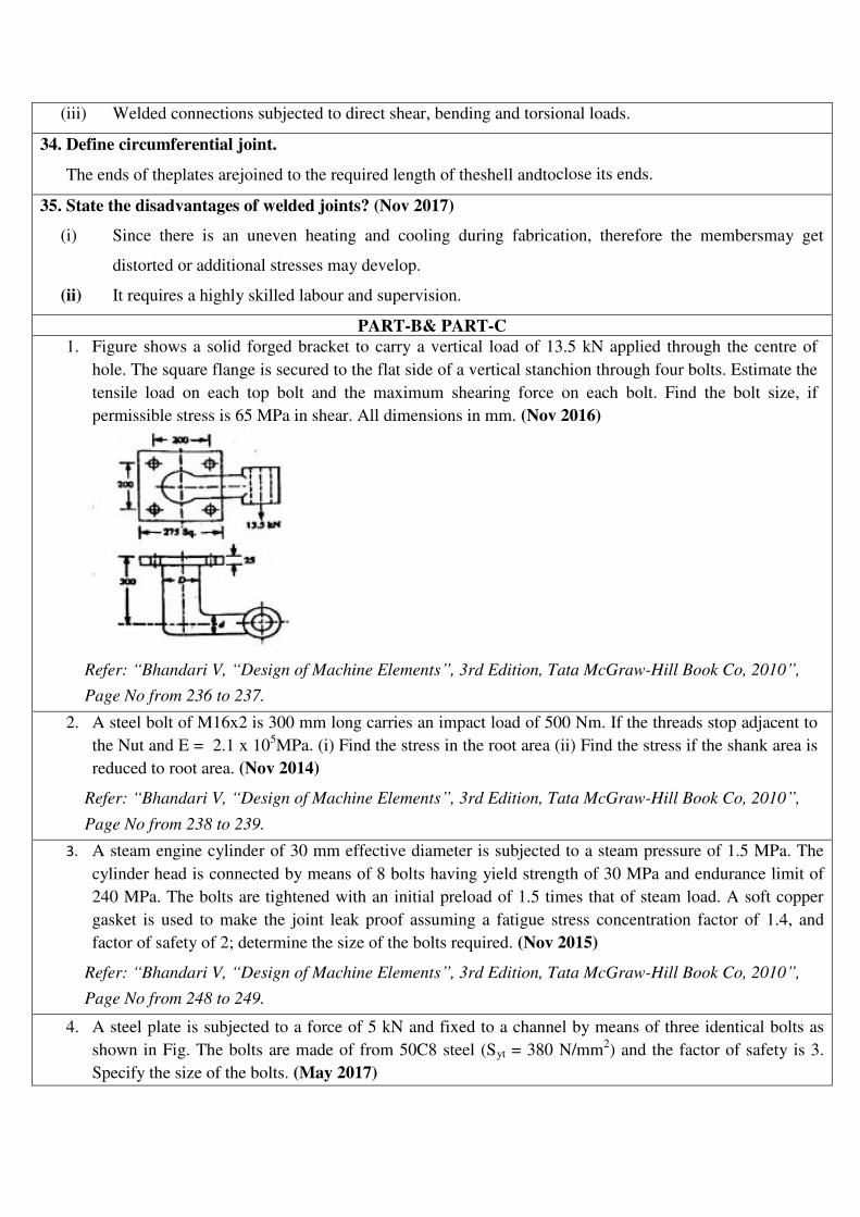
(iii) Welded connections subjected to direct shear, bending and torsional loads.
34. Define circumferential joint.
The ends of theplates arejoined to the required length of theshell andtoclose its ends.
35. State the disadvantages of welded joints? (Nov 2017)
(i) Since there is an uneven heating and cooling during fabrication, therefore the membersmay get
distorted or additional stresses may develop.
(ii) It requires a highly skilled labour and supervision.
PART-B& PART-C
1. Figure shows a solid forged bracket to carry a vertical load of 13.5 kN applied through the centre of
hole. The square flange is secured to the flat side of a vertical stanchion through four bolts. Estimate the
tensile load on each top bolt and the maximum shearing force on each bolt. Find the bolt size, if
permissible stress is 65 MPa in shear. All dimensions in mm. (Nov 2016)
Refer: “Bhandari V, “Design of Machine Elements”, 3rd Edition, Tata McGraw-Hill Book Co, 2010”,
Page No from 236 to 237.
2. A steel bolt of M16x2 is 300 mm long carries an impact load of 500 Nm. If the threads stop adjacent to
the Nut and E = 2.1 x 10⁵MPa. (i) Find the stress in the root area (ii) Find the stress if the shank area is
reduced to root area. (Nov 2014)
Refer: “Bhandari V, “Design of Machine Elements”, 3rd Edition, Tata McGraw-Hill Book Co, 2010”,
Page No from 238 to 239.
3. A steam engine cylinder of 30 mm effective diameter is subjected to a steam pressure of 1.5 MPa. The
cylinder head is connected by means of 8 bolts having yield strength of 30 MPa and endurance limit of
240 MPa. The bolts are tightened with an initial preload of 1.5 times that of steam load. A soft copper
gasket is used to make the joint leak proof assuming a fatigue stress concentration factor of 1.4, and
factor of safety of 2; determine the size of the bolts required. (Nov 2015)
Refer: “Bhandari V, “Design of Machine Elements”, 3rd Edition, Tata McGraw-Hill Book Co, 2010”,
Page No from 248 to 249.
4. A steel plate is subjected to a force of 5 kN and fixed to a channel by means of three identical bolts as
shown in Fig. The bolts are made of from 50C8 steel (Syt = 380 N/mm2) and the factor of safety is 3.
Specify the size of the bolts. (May 2017)
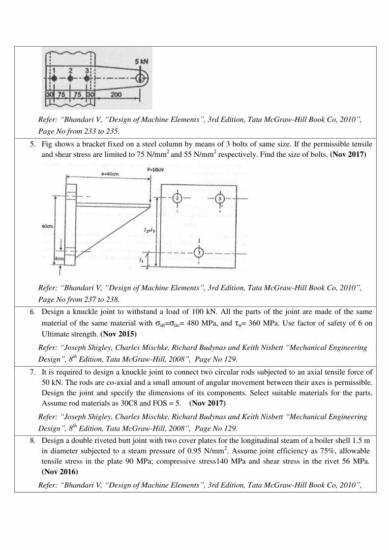
Refer: “Bhandari V, “Design of Machine Elements”, 3rd Edition, Tata McGraw-Hill Book Co, 2010”,
Page No from 233 to 235.
5. Fig shows a bracket fixed on a steel column by means of 3 bolts of same size. If the permissible tensile
and shear stress are limited to 75 N/mm2
and 55 N/mm2 respectively. Find the size of bolts. (Nov 2017)
Refer: “Bhandari V, “Design of Machine Elements”, 3rd Edition, Tata McGraw-Hill Book Co, 2010”,
Page No from 237 to 238.
6. Design a knuckle joint to withstand a load of 100 kN. All the parts of the joint are made of the same
material of the same material with ut= uc= 480 MPa, and u= 360 MPa. Use factor of safety of 6 on
Ultimate strength. (Nov 2015)
Refer: “Joseph Shigley, Charles Mischke, Richard Budynas and Keith Nisbett “Mechanical Engineering
Design”, 8th
Edition, Tata McGraw-Hill, 2008”, Page No 129.
7. It is required to design a knuckle joint to connect two circular rods subjected to an axial tensile force of
50 kN. The rods are co-axial and a small amount of angular movement between their axes is permissible.
Design the joint and specify the dimensions of its components. Select suitable materials for the parts.
Assume rod materials as 30C8 and FOS = 5. (Nov 2017)
Refer: “Joseph Shigley, Charles Mischke, Richard Budynas and Keith Nisbett “Mechanical Engineering
Design”, 8th
Edition, Tata McGraw-Hill, 2008”, Page No 129.
8. Design a double riveted butt joint with two cover plates for the longitudinal steam of a boiler shell 1.5 m
in diameter subjected to a steam pressure of 0.95 N/mm2. Assume joint efficiency as 75%, allowable
tensile stress in the plate 90 MPa; compressive stress140 MPa and shear stress in the rivet 56 MPa.
(Nov 2016)
Refer: “Bhandari V, “Design of Machine Elements”, 3rd Edition, Tata McGraw-Hill Book Co, 2010”,

Page No from 318 to 320.
9. A welded connection, as shown below is subjected to an eccentric force of 60 kN in the plane of welds.
Determine the size of the welds, if the permissible shear stress for the weld is 90 N/mm2. Assume static
conditions. (May 2015)
Refer: “Bhandari V, “Design of Machine Elements”, 3rd Edition, Tata McGraw-Hill Book Co, 2010”,
Page No from 285 to 287.
10. (i) A butt welded joint with ground and flush surface is subjected to tensile load which varies from 50
kN to 100 kN. Plates are 10 mm thick. Determine the length of weld required for over 2,500,000 cycles.
(May 2015)
Refer: “Bhandari V, “Design of Machine Elements”, 3rd Edition, Tata McGraw-Hill Book Co, 2010”,
Page No from 296 to 297.
(ii) The fig below shows an angle welded to a column and carries a static load F as shown. Determine the
ratio of the weld lengths La and Lb and Fa and Fb in terms of F. (May 2015)
Refer: “Bhandari V, “Design of Machine Elements”, 3rd Edition, Tata McGraw-Hill Book Co, 2010”,
Page No 284.
11. An ISA 200 x 100 x 100 angle is welded to a steel plate by means of fillet welds as shown in Fig (a). The
angle is subjected to a static force of 150 kN and permissible shear stress for the weld is 70 N/mm2.
Determine the lengths of the weld at the top and bottom. (Nov 2017)
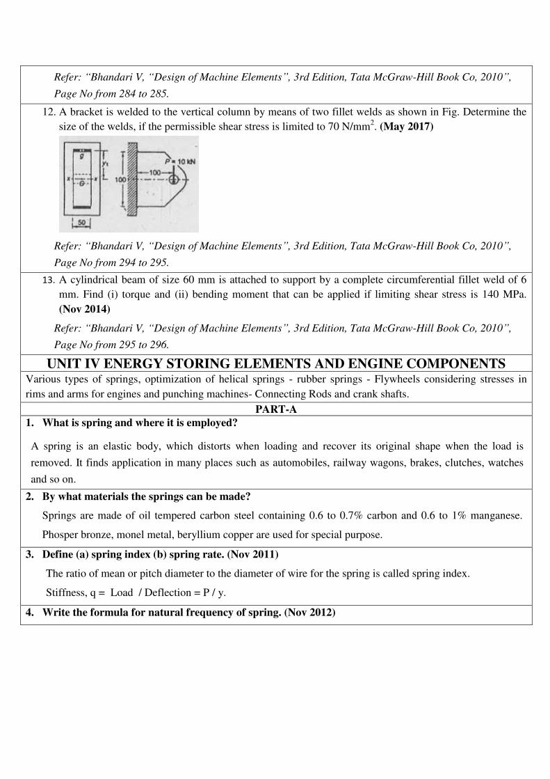
Refer: “Bhandari V, “Design of Machine Elements”, 3rd Edition, Tata McGraw-Hill Book Co, 2010”,
Page No from 284 to 285.
12. A bracket is welded to the vertical column by means of two fillet welds as shown in Fig. Determine the
size of the welds, if the permissible shear stress is limited to 70 N/mm2. (May 2017)
Refer: “Bhandari V, “Design of Machine Elements”, 3rd Edition, Tata McGraw-Hill Book Co, 2010”,
Page No from 294 to 295.
13. A cylindrical beam of size 60 mm is attached to support by a complete circumferential fillet weld of 6
mm. Find (i) torque and (ii) bending moment that can be applied if limiting shear stress is 140 MPa.
(Nov 2014)
Refer: “Bhandari V, “Design of Machine Elements”, 3rd Edition, Tata McGraw-Hill Book Co, 2010”,
Page No from 295 to 296.
UNIT IV ENERGY STORING ELEMENTS AND ENGINE COMPONENTS Various types of springs, optimization of helical springs - rubber springs - Flywheels considering stresses in
rims and arms for engines and punching machines- Connecting Rods and crank shafts. PART-A
1. What is spring and where it is employed?
A spring is an elastic body, which distorts when loading and recover its original shape when the load is
removed. It finds application in many places such as automobiles, railway wagons, brakes, clutches, watches
and so on.
2. By what materials the springs can be made?
Springs are made of oil tempered carbon steel containing 0.6 to 0.7% carbon and 0.6 to 1% manganese.
Phosper bronze, monel metal, beryllium copper are used for special purpose.
3. Define (a) spring index (b) spring rate. (Nov 2011)
The ratio of mean or pitch diameter to the diameter of wire for the spring is called spring index.
Stiffness, q = Load / Deflection = P / y.
4. Write the formula for natural frequency of spring. (Nov 2012)
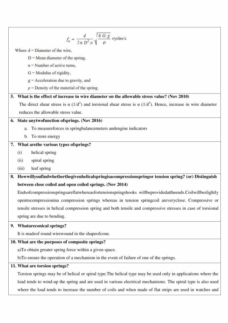
5. What is the effect of increase in wire diameter on the allowable stress value? (Nov 2010)
The direct shear stress is α (1/d2) and torsional shear stress is α (1/d3
). Hence, increase in wire diameter
reduces the allowable stress value.
6. State anytwofunction ofsprings. (Nov 2016)
a. To measureforces in springbalancemeters andengine indicators
b. To store energy
7. What arethe various types ofsprings?
(i) helical spring
(ii) spiral spring
(iii) leaf spring
8. Howwillyoufindwhetherthegivenhelicalspringisacompressionspringor tension spring? (or) Distinguish
between close coiled and open coiled springs. (Nov 2014)
Endsofcompressionspringsareflatwhereasfortensionspringshooks willbeprovidedattheends.Coilwillbeslightly
opentocompressionina compression springs whereas in tension springcoil areveryclose. Compressive or
tensile stresses in helical compression spring and both tensile and compressive stresses in case of torsional
spring are due to bending.
9. Whatareconical springs?
It is madeof round wirewound in the shapeofcone.
10. What are the purposes of composite springs?
a)To obtain greater spring force within a given space.
b)To ensure the operation of a mechanism in the event of failure of one of the springs.
11. What are torsion springs?
Torsion springs may be of helical or spiral type.The helical type may be used only in applications where the
load tends to wind-up the spring and are used in various electrical mechanisms. The spiral type is also used
where the load tends to increase the number of coils and when made of flat strips are used in watches and
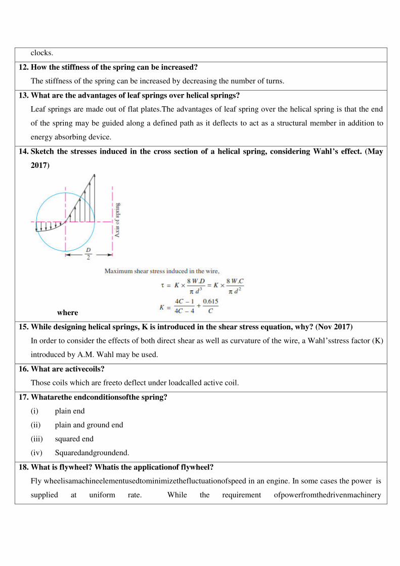
clocks.
12. How the stiffness of the spring can be increased?
The stiffness of the spring can be increased by decreasing the number of turns.
13. What are the advantages of leaf springs over helical springs?
Leaf springs are made out of flat plates.The advantages of leaf spring over the helical spring is that the end
of the spring may be guided along a defined path as it deflects to act as a structural member in addition to
energy absorbing device.
14. Sketch the stresses induced in the cross section of a helical spring, considering Wahl’s effect. (May
2017)
where
15. While designing helical springs, K is introduced in the shear stress equation, why? (Nov 2017)
In order to consider the effects of both direct shear as well as curvature of the wire, a Wahl’sstress factor (K)
introduced by A.M. Wahl may be used.
16. What are activecoils?
Those coils which are freeto deflect under loadcalled active coil.
17. Whatarethe endconditionsofthe spring?
(i) plain end
(ii) plain and ground end
(iii) squared end
(iv) Squaredandgroundend.
18. What is flywheel? Whatis the applicationof flywheel?
Fly wheelisamachineelementusedtominimizethefluctuationofspeed in an engine. In some cases the power is
supplied at uniform rate. While the requirement ofpowerfromthedrivenmachinery
isvariable.Eg:punchingpress drivenby theelectricmotor,rollingmilldrivenbyanelectricmotor.Inthiscasethe
flywheel storeenergyduring the idleportion oftheworkcyclebyincreasingits speed and delivers this
energy.Duringthepeak load period ofpunching.
19. What type of stresses is produced in a disc flywheel? (Nov 2010)
a. Tensile stress due to centrifugal force.
b. Tensile bending stress caused by the restraint of the arms and
c. The shrinkage stresses due to unequal rate of cooling of casting.
20. What is the main function of a flywheel in an engine? (Nov 2013) (Nov 2015)
A flywheel is a heavy rotating mass which is placed between the power source and the driven member to
act as a reservoir of energy. The primary function of flywheel is to act an ‘energy accumulator’. It will
absorb energy when demand is less than the supply of energy and will release it when the demand is more
than the energy being supplied.
21. State anytwo typeof flywheel.
(i) Disctype
(ii) Web type.
22. What is flywheeleffect?
Themassmomentofinertiarequiredforthefly wheelistermedas flywheel effect.
23. Define coefficient of fluctuation of speed in thecaseof flywheel? Definethe term fluctuation of energy.
(Nov 2014)
Coefficientoffluctuationofspeedistheratioofmaximumchangeof speed to mean speed of the flywheel.
Theratiooffluctuationofenergytothemeanenergyiscalledcoefficient of fluctuation of energy.
24. What arethe stresses induced in flywheels arms?
(i) tensilestress due to centrifugalforce
(ii) bendingstress due to torque
(iii)stress due to belttension
25. Howdoes the function of flywheel differfrom that ofgovernor? (Nov 2016)
A governor regulates the mean speed of an engine when there are variationsinthemeanloads.Itautomatically
controlsthesupply ofworkingfluidto engine withthevaryingloadconditionandkeepsthe meanspeedwithinthe
limits.It doesnotcontrolthespeedvariationcaused by thevaryingload.Aflywheeldoesnot maintain constant
speed.
26. Brief why flywheels are used in punching machines. (Nov 2017)
In machines where the operation is intermittent like punching machines, shearing machines,riveting
machines, crushers etc., the flywheel stores energy from the power source during the greaterportion of the
operating cycle and gives it up during a small period of the cycle. Thus the energy fromthe power source to
the machines is supplied practically at a constant rate throughout the operation.
27. At what angle of the crank the twisting moment is maximum in the crankshaft? (Nov 2011)
The crank angle for maximum twisting moment usually lies between 25o and 35
o from TDC for petrol
engines and between 30o and 40
o for diesel engines.
28. Why is piston end of a connecting rod kept smaller than the crank pin end? (Nov 2010)
The piston end of the connecting rod experiences less bending moment than the crack end. Hence, on the
basis of ‘beam of uniform strength’, the piston end of the performance & life.
29. Under what force, the big end bolts and caps are designed? (Nov 2011)
The big end bolts and caps are designed for inertia (Fi) force due to reciprocating parts.
30. What are functions ofcrankshafts? Classifycrankshafts.
Crankshafts areusedto convent lotterymotion into reciprocatingmotion. Two types are:
Single throw crankshafts and Multithrow crankshafts.
31. What is a connecting rod? What are materials used for connecting rod?
Connecting rod is a machine member, which used to transmit power from a reciprocating member to rotary
one or vice versa.Mild steel and alloy of aluminium for light duty. Alloy steels of molybdenum and
chromium are used for heavy duty.
32. What are the stresses set up in an IC engine connecting rod? Why I- section is chosen for the
connecting rod?
Types of stresses are: Tensile stress, Compressive stress and Bending stress due to inertia force.The “I”
section of the connecting rod is used due to its lightness and to keep the inertia forces as low as possible. It
can also with stand high gas pressure.
33. What type of external forces act on connecting rod?(May 2017)
The external forces acting on connecting rod are Forces due to gas or steam pressure and inertia of
reciprocating parts
Inertia forces.
PART-B& PART-C
1. Designaleafspringforthefollowingspecifications for a truck: Assume FOS = 2. Maximum load on
springs =100kN;Number ofsprings=4; Material of springs = Cr Va Steel ( u = 1380 MPa and E = 206 x
103MPa); Spanofthe spring =1000mm; Width of central ban = 150 mm; Permissibledeflection=100mm.
Assume 2 full length leaves and 6 graduated leaves. (May 2015)
Refer: “Bhandari V, “Design of Machine Elements”, 3rd Edition, Tata McGraw-Hill Book Co, 2010”,

Page No from 437 to 438.
2. Design of helical compression spring to sustain an axial load of 4 kN. The deflection is 80 mm. Spring
index is 6. The shear stress is not to exceed 350 MPa. Rigidity modulus for spring material is 81 GPa.
(May 2015)
Refer: “Bhandari V, “Design of Machine Elements”, 3rd Edition, Tata McGraw-Hill Book Co, 2010”,
Page No from 407 to 408.
3. A railway wagon moving at a velocity of 1.5 m/s is brought to rest by bumper consisting of two helical
springs arranged in parallel. The mass of the wagon is 1500 kg. The springs are compressed by 150 mm
in bringing the wagon to rest. The spring index can be taken as 6. The springs are made of oil-hardened
and tempered steel wire with ultimate tensile strength of 1250 MPa and modulus of rigidity of 81.37
GPa. The permissible shear stress for the spring can be taken as 50% of the ultimate tensile strength.
Design the spring and calculate (i) wire diameter (ii) mean coil diameter (iii) number of active coils (iv)
total number of coils (v) solid length (vi) free length and (vii) pitch of the coil. (Nov 2015)
Refer: “Bhandari V, “Design of Machine Elements”, 3rd Edition, Tata McGraw-Hill Book Co, 2010”,
Page No from 413 to 415.
4. A spring loaded safety valve for a boiler is required to blow off at a pressure of 0.8 MPa. The diameter
of valve seat is 90 mm and maximum lift of valve is 10 mm. Design a suitable spring for the valve
assuming the spring index as 7. Provide an initial compression of 30 mm. Take allowable shear stress as
420 MPa.(Nov 2017)
Refer: “Bhandari V, “Design of Machine Elements”, 3rd Edition, Tata McGraw-Hill Book Co, 2010”,
Page No from 417 to 418.
5. A 5 kW induction motor, running at 960 rpm operates a riveting machine. The flywheel fitted to it, is of
mass 120 kg, with radius of gyration equal to 0.35 m. Each riveting takes 1 second and requires 9 kW.
Determine (i) the number of rivets formed per hour and (ii) the reduction in speed of the flywheel, after
the riveting operation. (Nov 2015)
Refer: “Bhandari V, “Design of Machine Elements”, 3rd Edition, Tata McGraw-Hill Book Co, 2010”,
Page No from 760 to 761.
6. Design a closed coil helical spring subjected a tensile load of magnitude varying from 2500 N to 3000 N
and the axial deflection of spring for this range of load is 6.5 mm. Design the spring, taking the spring
index as 6 and safe shear stress for material equal to 465 MPa. (Nov 2014)
Refer: “Bhandari V, “Design of Machine Elements”, 3rd Edition, Tata McGraw-Hill Book Co, 2010”,
Page No from 419 to 420.
7. A helical compression spring of the exhaust valve mechanism is initially compressed with a preload of
375 N. When the spring is further compressed and the valve is fully opened, the torsional shear stress in
the spring wire should not exceed 750 N/mm2. Due to space limitations, the outer diameter of the spring
should not exceed 42 mm. The spring is to be designed for minimum weight. Calculate the wire diameter
and the mean coil diameter of the spring. (May 2017)
Refer: “Bhandari V, “Design of Machine Elements”, 3rd Edition, Tata McGraw-Hill Book Co, 2010”,
Page No from 407 to 408.
8. Design a CI flywheel for a four stroke engine developing 150 kW at 200 rpm. Calculate the mean
diameter of the flywheel if the hoop stress is not to exceed 4 MPa. Total fluctuation of speed is to be 4%
of the mean speed. Work done during the power stroke may be assumed to be 1.5 times the average work
done during the cycle. Density of CI is 7200 kg/m3. (Nov 2014)
Refer: “Bhandari V, “Design of Machine Elements”, 3rd Edition, Tata McGraw-Hill Book Co, 2010”,
Page No from 758 to 759.
9. The areas of the turning moment diagram for one revolution of a multicylinder engine with reference to
the mean turning moment, below and above the line, are -32, +408, -267, +333, -310, +226, -374, ± 260
and -244 mm2. The scale for abscissa and ordinate are : 1 mm = 2.4
o and 1 mm = 650 Nm respectively.
The main speed is 300 rpm with a percentage of speed fluctuation of ±1.5%. If the hoop stress in the
material of the rim is not to exceed 5.6 MPa, determine the suitable diameter and cross section for the
flywheel, assuming that the width is equal to 4 times the thickness. The density of material may be taken
as 7200 kg/m3. Neglect the effect of the boss and arms. (Nov 2016)(May 2014)
Refer: “Bhandari V, “Design of Machine Elements”, 3rd Edition, Tata McGraw-Hill Book Co, 2010”,
Page No from 764 to 765.
10. A punching machine carries out punching 10 holes per minute. Each hole of 36 mm diameter in 16 mm
thick plate requires 7 N-m of energy/mm2 of the sheared area. The punch has a stroke of 90 mm.
Determine the power of the motor required to operate the machine.
If the total fluctuation of speed is not to exceed 2.5% of the mean speed; determine the mass of the
flywheel. The mean speed of the flywheel is 15 m/s.(May 2017)
Refer: “Bhandari V, “Design of Machine Elements”, 3rd Edition, Tata McGraw-Hill Book Co, 2010”,
Page No from 763 to 764.
11. A punching machine makes 25 workings stokes per minute and is capable of punching 25 mm diameter
holes in 18 mm thick steel plates having ultimate shear strength of 3000 kg/cm2. The punching operation
takes place during 1/10th
of a revolution of the crank shaft. Estimate the horse power needed for the
driving motor, assuming a mechanical efficiency of 95%. Determine suitable dimensions for the rim
cross section of the flywheel, which is to revolve at 9 times the speed of crankshaft. The permissible
fluctuation of speed is 0.1. The flywheel is to be made of cast iron having a working stress (tensile) of 60
kg/cm2 and weighing 7.25 gm/cu.cm. The diameter of the flywheel must not exceed 149 cm owing to
space restrictions. The hub and spokes may be assumed to provide 5% of the rotational inertia of the
wheel. Check for the centrifugal stress induced in the rim. (Nov 2017)
Refer: “Bhandari V, “Design of Machine Elements”, 3rd Edition, Tata McGraw-Hill Book Co, 2010”,
Page No from 761 to 762.
UNIT V BEARINGS Sliding contact and rolling contact bearings - Hydrodynamic journal bearings, Sommerfeld Number, Raimondi
and Boyd graphs, -- Selection of Rolling Contact bearings.
PART-A 1. What is bearing?
Bearingis a stationarymachine element which supports a rotatingshafts or axles and confines its motion.
2. Classify the types of bearings. (Nov 2016)
i) Depending upon the type of load coming upon the shaft:
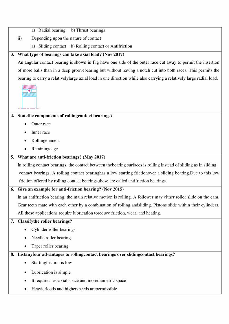
a) Radial bearing b) Thrust bearings
ii) Depending upon the nature of contact
a) Sliding contact b) Rolling contact or Antifriction
3. What type of bearings can take axial load? (Nov 2017)
An angular contact bearing is shown in Fig have one side of the outer race cut away to permit the insertion
of more balls than in a deep groovebearing but without having a notch cut into both races. This permits the
bearing to carry a relativelylarge axial load in one direction while also carrying a relatively large radial load.
4. Statethe components of rollingcontact bearings?
Outer race
Inner race
Rollingelement
Retainingcage
5. What are anti-friction bearings? (May 2017)
In rolling contact bearings, the contact between thebearing surfaces is rolling instead of sliding as in sliding
contact bearings. A rolling contact bearinghas a low starting frictionover a sliding bearing.Due to this low
friction offered by rolling contact bearings,these are called antifriction bearings.
6. Give an example for anti-friction bearing? (Nov 2015)
In an antifriction bearing, the main relative motion is rolling. A follower may either rollor slide on the cam.
Gear teeth mate with each other by a combination of rolling andsliding. Pistons slide within their cylinders.
All these applications require lubrication toreduce friction, wear, and heating.
7. Classifythe roller bearings?
Cylinder roller bearings
Needle roller bearing
Taper roller bearing
8. Listanyfour advantages to rollingcontact bearings over slidingcontact bearings?
Startingfriction is low
Lubrication is simple
It requires lessaxial space and morediametric space
Heavierloads and higherspeeds arepermissible
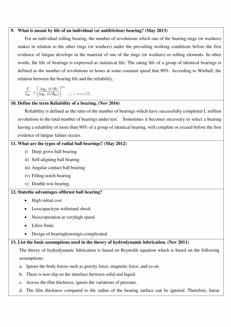
9. What is meant by life of an individual (or antifriction) bearing? (May 2013)
For an individual rolling bearing, the number of revolutions which one of the bearing rings (or washers)
makes in relation to the other rings (or washers) under the prevailing working conditions before the first
evidence of fatigue develops in the material of one of the rings (or washers) or rolling elements. In other
words, the life of bearings is expressed as statistical life. The rating life of a group of identical bearings is
defined as the number of revolutions or hours at some constant speed that 90%. According to Wiebull, the
relation between the bearing life and the reliability,
10. Define the term Reliability of a bearing. (Nov 2016)
Reliability is defined as the ratio of the number of bearings which have successfully completed L million
revolutions to the total number of bearings under test. Sometimes it becomes necessary to select a bearing
having a reliability of more than 90% of a group of identical bearing, will complete or exceed before the first
evidence of fatigue failure occurs.
11. What are the types of radial ball bearings? (May 2012)
i) Deep grove ball bearing
ii) Self-aligning ball bearing
iii) Angular contact ball bearing
iv) Filling notch bearing
v) Double row bearing.
12. Statethe advantages ofthrust ball bearing?
High initial cost
Lesscapacityto withstand shock
Noisyoperation at veryhigh speed
Lifeis finite
Design of bearinghousingis complicated
13. List the basic assumptions used in the theory of hydrodynamic lubrication. (Nov 2011)
The theory of hydrodynamic lubrication is based on Reynolds equation which is based on the following
assumptions:
a. Ignore the body forces such as gravity force, magnetic force, and so on.
b. There is non-slip on the interface between solid and liquid.
c. Across the film thickness, ignore the variations of pressure.
d. The film thickness compared to the radius of the bearing surface can be ignored. Therefore, linear
velocity is used to calculate instead of rotational speed to neglect speed to neglect the influence of film
curvature.
e. Lubricants are Newtonian.
f. The flow is laminar and it is not a boundary layer or turbulence.
g. Compared to the viscous force, the inertia force can be ignored, including the acceleration force and
centrifugal force.
h. Across the lubricant film thickness, viscosity remains unchanged.
14. List the advantages of hydrostatic bearings? (Nov 2017)
The hydrostatic bearings are thosewhich can support steady loads without any relative motion between the
journal and the bearing.This is achieved by forcing externally pressurized lubricant between the members.
15. What is load rating?
Theload carryingcapacityofa rolling element bearingiscalled load rating.
16. Define the term bearing life.
The life of a radial ball bearing is the number of revolutions or hours at a given constant speed that the
bearing runs before the first evidence of fatigue develops in the material of either ring or in a ball.
17. Define static capacity of bearing. (Nov 2014)
It is defined as load acting on a non-rotating bearing under which permanent deformation is 0.0001 times the
ball or roller diameter.
18. Explain the term Dynamicload carrying capacities of rollingcontact bearing? (Nov 2012)
Dynamicload ratingis defined as theradial load in radial bearings that can becarried foraminimum lifeof
onemillion revolutions.
19. Listanysix types of bearingmaterials?
Lead basebabbit
Tin basebabbit
Leaded bronze
Copper lead alloy
Gun metal
Phosphor bronze
20. What are the required properties of bearing materials?
i) High compressive strength
ii) Low coefficient of friction
iii) High thermal conductivity
iv) High resistance to corrosion
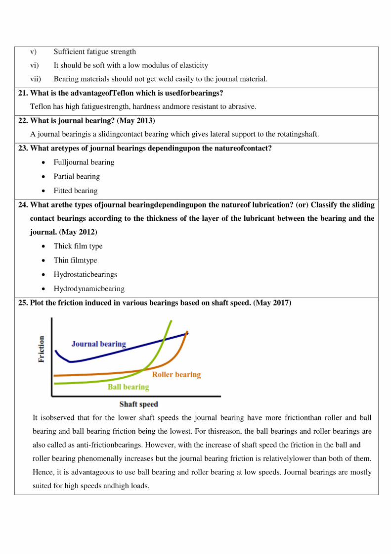
v) Sufficient fatigue strength
vi) It should be soft with a low modulus of elasticity
vii) Bearing materials should not get weld easily to the journal material.
21. What is the advantageofTeflon which is usedforbearings?
Teflon has high fatiguestrength, hardness andmore resistant to abrasive.
22. What is journal bearing? (May 2013)
A journal bearingis a slidingcontact bearing which gives lateral support to the rotatingshaft.
23. What aretypes of journal bearings dependingupon the natureofcontact?
Fulljournal bearing
Partial bearing
Fitted bearing
24. What arethe types ofjournal bearingdependingupon the natureof lubrication? (or) Classify the sliding
contact bearings according to the thickness of the layer of the lubricant between the bearing and the
journal. (May 2012)
Thick film type
Thin filmtype
Hydrostaticbearings
Hydrodynamicbearing
25. Plot the friction induced in various bearings based on shaft speed. (May 2017)
It isobserved that for the lower shaft speeds the journal bearing have more frictionthan roller and ball
bearing and ball bearing friction being the lowest. For thisreason, the ball bearings and roller bearings are
also called as anti-frictionbearings. However, with the increase of shaft speed the friction in the ball and
roller bearing phenomenally increases but the journal bearing friction is relativelylower than both of them.
Hence, it is advantageous to use ball bearing and roller bearing at low speeds. Journal bearings are mostly
suited for high speeds andhigh loads.
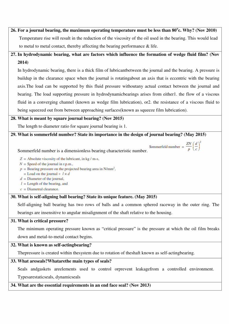
26. For a journal bearing, the maximum operating temperature must be less than 80oc. Why? (Nov 2010)
Temperature rise will result in the reduction of the viscosity of the oil used in the bearing. This would lead
to metal to metal contact, thereby affecting the bearing performance & life.
27. In hydrodynamic bearing, what are factors which influence the formation of wedge fluid film? (Nov
2014)
In hydrodynamic bearing, there is a thick film of lubricantbetween the journal and the bearing. A pressure is
buildup in the clearance space when the journal is rotatingabout an axis that is eccentric with the bearing
axis.The load can be supported by this fluid pressure withoutany actual contact between the journal and
bearing. The load supporting pressure in hydrodynamicbearings arises from either1. the flow of a viscous
fluid in a converging channel (known as wedge film lubrication), or2. the resistance of a viscous fluid to
being squeezed out from between approaching surfaces(known as squeeze film lubrication).
28. What is meant by square journal bearing? (Nov 2015)
The length to diameter ratio for square journal bearing is 1.
29. What is sommerfeld number? State its importance in the design of journal bearing? (May 2015)
Sommerfeld number is a dimensionless bearing characteristic number.
30. What is self-aligning ball bearing? State its unique feature. (May 2015)
Self-aligning ball bearing has two rows of balls and a common sphered raceway in the outer ring. The
bearings are insensitive to angular misalignment of the shaft relative to the housing.
31. What is critical pressure?
The minimum operating pressure known as “critical pressure” is the pressure at which the oil film breaks
down and metal-to-metal contact begins.
32. What is known as self-actingbearing?
Thepressure is created within thesystem due to rotation of theshaft known as self-actingbearing.
33. What areseals?Whatarethe main types of seals?
Seals andgaskets areelements used to control orprevent leakagefrom a controlled environment.
Typesarestaticseals, dynamicseals
34. What are the essential requirements in an end face seal? (Nov 2013)
i) Surfaces of the seals (stationary and rotating) should be polished and perfectly flat.
ii) Seal faces must be perpendicular to the shaft.
iii) Spring force should be sufficient to hold the sea faces in contact.
iv) No friction between shaft and seal parts.
35. Howis “O” ringdesignated?
An “O”ringis designated as “internal diameter×thickness”.
PART-B& PART-C
1. Enumerate the detail steps involved in the selection of bearings from the manufacturer’s catalogue. (May
2015)
Refer: “Bhandari V, “Design of Machine Elements”, 3rd Edition, Tata McGraw-Hill Book Co, 2010”,
Page No from 573 to 575.
2. Design a journal bearing for 12 MW, 1000 rpm steam turbine, which is supported by two bearings. Take
the atmospheric temperatures as 60oC. Assume viscosity of oil as 23 centistokes. (Nov 2016)
Refer: “Bhandari V, “Design of Machine Elements”, 3rd Edition, Tata McGraw-Hill Book Co, 2010”,
Page No from 629 to 630.
3. Load on a hydrodynamic full journal bearing is 30 kN. The diameter and speed of the shaft are 150 mm and
1200 mm respectively. Diametral clearance 0.2 mm. Sommerfield number is 0.631. L/D ratio 1:1.
Calculate temperature rise of oil, quantity of the oil, heat generated and type of oil required. (May 2015)
Refer: “Bhandari V, “Design of Machine Elements”, 3rd Edition, Tata McGraw-Hill Book Co, 2010”,
Page No from 629 to 630.
4. A full journal bearing of 50 mm diameter and 100 mm long has a bearing pressure of 1.4 MPa. The speed
of the journal is 900 rpm and the ratio of journal diameter to the diametrical tolerance is 1000. The bearing
is lubricated with oil whose absolute viscosity at the operating temperature of 75oc may be taken as 0.011
kg/m-s. The room temperature is 35oc. Find (i) the amount of artificial cooling required and (ii) the mass
of the lubricating oil required, if the difference between the outlet and inlet temperature of the oil is 10oc.
Take specific heat of the oil as 1850 J/kg/oc. (Nov 2015)
Refer: “Bhandari V, “Design of Machine Elements”, 3rd Edition, Tata McGraw-Hill Book Co, 2010”,
Page No from 632 to 633.
5. Design a journal bearing for a 49.9 mm diameter journal. It is ground and hardened and is rotating at 1500
rpm in a bearing of diameter and length both 50 mm. The inlet temperature of oil 65oC. Determine max
radial load that the journal can carry and power loss. (May 2017) (Nov 2017)
Refer: “Bhandari V, “Design of Machine Elements”, 3rd Edition, Tata McGraw-Hill Book Co, 2010”,
Page No from 629 to 630.
6. A 50 mm diameter journal bearing rotates at 1500 rpm, L/D = 1, radial clearance is 0.05 mm, minimum
film thickness = 0.01 mm. Calculate the maximum radial load that the journal bearing can carry and still
operate under hydrodynamic condition. For this load, calculate the power lost in friction and increase in
the oil temperature. Assume Hg = Hd. Absolute viscosity = 20 x 103Pas, Sp.Gravity of oil 0.8, Sp.Heat of
oil 2.1 kJ/KgoC. (Nov 2014)
Refer: “Bhandari V, “Design of Machine Elements”, 3rd Edition, Tata McGraw-Hill Book Co, 2010”,
Page No from 630 to 631.
7. Select a single row deep groove ball bearing for a radial load of 4000 N and an axial load of 5000 N,

operating at a speed of 1600 rpm for an average life of 5 years at 10 hours per day. Assume uniform and
steady load. (Nov 2015)
Refer: “Bhandari V, “Design of Machine Elements”, 3rd Edition, Tata McGraw-Hill Book Co, 2010”,
Page No from 582 to 583.
8. A ball bearing is subjected to a radial load of 10 kN and a thrust load of 5 kN. The inner ring rotates at 1000
rpm. The average life is to be 5000 hours. What basic load rating must be used to select a bearing for this
purpose? Take Fa/Co = 0.5 and assume service factor 1.5.(May 2017)
Refer: “Bhandari V, “Design of Machine Elements”, 3rd Edition, Tata McGraw-Hill Book Co, 2010”,
Page No from 584 to 585.
9. A deep groove ball bearing No.6308 selected for a particular application, carries a radial load of 2900 N and
a thrust load of 1800 N; both being steady. The inner race of the bearing rotates at 900 rpm. The bearing is
required to have a minimum life of 9000 hours. Check whether the bearing selected can serve the purpose.
(Nov 2017)
Refer: “Bhandari V, “Design of Machine Elements”, 3rd Edition, Tata McGraw-Hill Book Co, 2010”,
Page No from 583 to 584.
10. A ball bearing subjected to a radial load of 5 kN is expected to have a life of 8000 hours at 1450 rpm with
a reliability of 99%. Calculate the dynamic load capacity of the bearing so that it can be selected from the
manufacturer’s catalogue based on a reliability of 90%. (Nov 2016)
Refer: “Bhandari V, “Design of Machine Elements”, 3rd Edition, Tata McGraw-Hill Book Co, 2010”,
Page No from 593 to 594.
11. Find the rated load of deep groove ball bearing for the following load cycle.
SL NO RADIAL LOAD (N) AXIAL LOAD (N) % OF TIME
1 3500 1000 15
2 3500 1000 20
3 3500 10 30
4 500 2000 35
Also find the 90% life of ball bearing if bearing used is 6207 with dynamic capacity 19620 N. (Nov
2014)
Refer: “Bhandari V, “Design of Machine Elements”, 3rd Edition, Tata McGraw-Hill Book Co, 2010”,
Page No from 594 to 595.