jeol 5800lv scanning electron microscope...
TRANSCRIPT
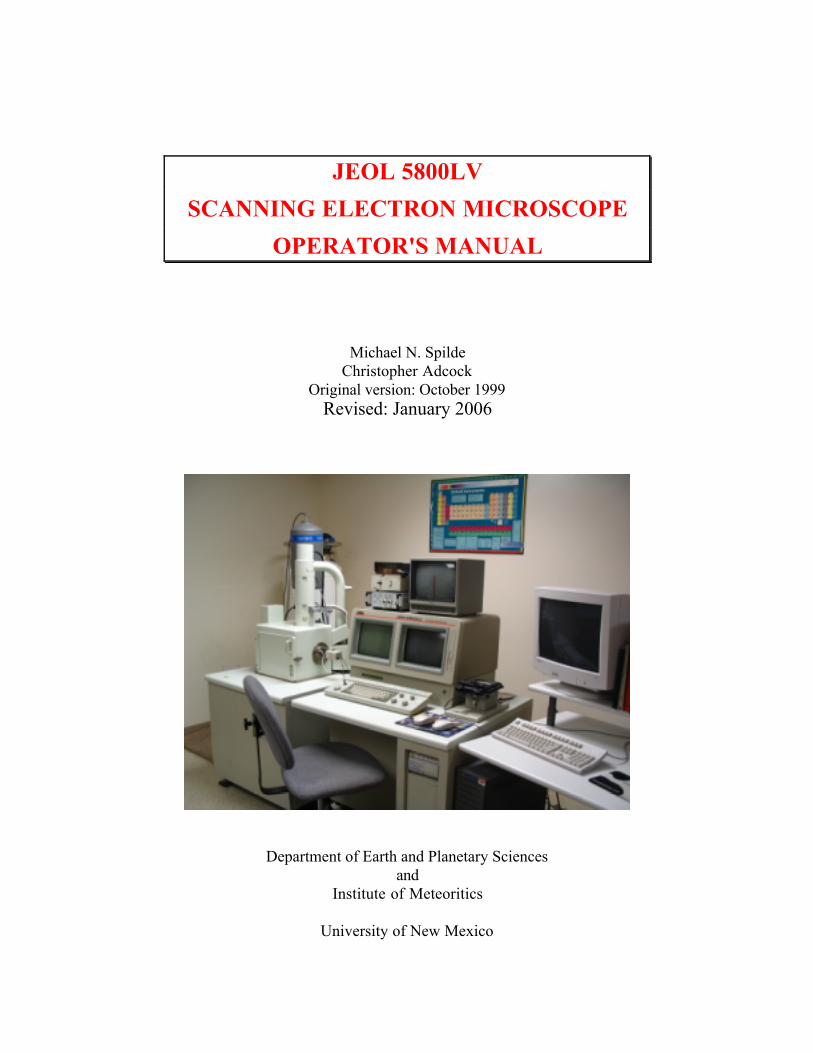
JEOL 5800LV
SCANNING ELECTRON MICROSCOPE
OPERATOR'S MANUAL
Michael N. SpildeChristopher Adcock
Original version: October 1999Revised: January 2006
Department of Earth and Planetary Sciencesand
Institute of Meteoritics
University of New Mexico
Introduction
1
INTRODUCTION
This document is an introduction to the operation of the JEOL 5800LV scanningelectron microscope and the Oxford Isis 300 analytical system. This manual should beconsidered a work in progress. With time, we will add sections as operating proceduresare developed or improved by user experience. This manual is not intended to be formalinstrument documentation, but rather, a hands-on users guide to the integrated operationof both the microscope and analyzer. Details of microscope operation, the EDSanalytical system, and the computer software can be found in the manufacturer’s manualskept in the lab. Unfortunately the JEOL reference manual is poorly translated fromJapanese and is difficult to understand, and thus is a limited resource. The Oxfordsoftware manuals are a useful resource, with reference and tutorial sections for most ofthe software packages.
The first part of this manual consists of a brief introduction to the JEOL 5800 andthe Oxford analytical system. This is followed by a comprehensive checklist for settingup, starting, and shutting down the instrument. This section is divided into two parts:one for operation in high vacuum and the other for operation in low vacuum mode.Sections then follow for EDS analysis, collection and manipulation of images and x-raymaps, and operation of the cathodoluminescence detector. An appendix section isincluded that deals with emergencies and potential problem areas. Users should proceedstepwise through the sections on loading samples and instrument set up and then proceedto the appropriate section(s) for imaging, X-ray analysis, etc.
THE JEOL 5800LV
The JEOL 5800 SEM is a sophisticated scanning electron microscope that wasdesigned to operate in either high or low vacuum (the LV connotation indicates thepresence of the "low vacuum" controls). The electron column contains a pressuredifferential aperture that allows the specimen chamber to be operated at a low (or poor)vacuum while the rest of the column and gun are maintained at a high vacuum. In thisoperating mode, two separate rotary vacuum pumps are used: one to back the diffusionpump that pumps the column and another to pump directly on the chamber. When thesystem is operated in high vacuum mode, the diffusion pump and its rotary pump areused to maintain equal vacuum in the column and chamber.
The microscope is controlled by an internal computer through a menu-drivensoftware interface. The motorized stage is operated from a joy stick, and the singlejoystick serves several functions which are set by buttons on the keyboard. Likewise,several knobs on the keyboard serve different functions which are selected from keyboardbuttons. The computer has a command line interpreter, so that in addition to manualoperation from the various knobs, buttons and joystick, many of the functions can beaccomplished by commands typed from the keyboard. The instrument's computer canalso receive instructions and be controlled by other independent computers throughRS232 and SCSI ports.
Introduction
2
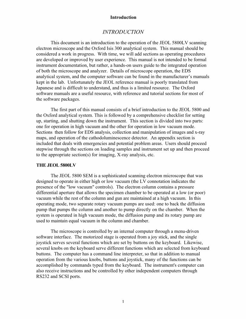
Figure 1. Components of the JEOL scanning electron microscope and Oxford analyzersystem.
The SEM is equipped with detectors for imaging of secondary electrons (SE) ,backscattered electrons (BSE), x-rays, and cathodoluminescence (CL). The SE detector isa highly efficient Everhart-Thornly detector for imaging at all scan rates in high vacuum.The Everhart-Thornly detector cannot be used in the low vacuum mode, and its functionis replaced by the BSE detector. This detector consists of an annular ring mounted underthe objective lens and another flat detector a short distance from the lens, creating aparallax from which topographic information is derived in the low vacuum mode. TheEDS can be utilized in both vacuum modes, but requires a working distance of 15 mm orless. The CL detector is an independent optical device that must be inserted into theelectron path with the stage at a specific height. Only the SE detector can be used withthe CL inserted.
THE OXFORD ISIS 300
The Oxford analytical system consists of the EDS detector, an interface box and astandard desk-top computer. The EDS has an ultra-thin window installed and cantherefore detect elements from boron and up (Z≥5). The detector is controlled from theOxford interface, which contains the electronic hardware for the EDS signal and imageacquisition, along with microscope automation hardware. The interface passes
Introduction
3
information to and receives commands from the user through the Oxford software on thePC computer. The PC is an HP Vectra with a 200 MHz Pentium CPU, a 2 GB harddrive, a single 3 1/2" high-density floppy disk drive, a CD-Rom, and a 100 MB IomegaZip™ drive communicating through a SCSI port. Software is operated in the Windows95 operating environment. The system is attached to the EPS local area network (LAN)via ethernet connection.
Image and EDS acquisition is accomplished through Oxford Windows software.The software is modular in design, and many of the available modules have been installed.There are four primary modules: X-ray Analysis, Autobeam, Automation, and IMQuant.Two additional mudules are Detector Calibration and Notepad. All of these primarymodules are accessed through Labbook™, Oxford's information database system.Qualitative x-ray identification, quantitative analysis, and x-ray mapping are availablethrough the X-ray Analysis module. SE, BSE and CL images are acquired through theAutobeam module. This module is also the access point for several image analysissubsystems, including Cameo™, area analysis and phase analysis software. TheAutomation module controls stage movement and electron colunm functions for operatingthe microscope in an automated mode. Finally, the manipulation, processing, andanalysis of image is done in the IMQuant module.
Data transfer from the SEM to the "outside world" can take place on a variety ofmedia. Images can be acquired and printed directly from the SEM to Polaroid film or to athermal image printer. These digital images can be saved directly, in TIFF format, to afloppy disk on the JEOL, which is the highest resolution available (see Appedix A, Table1). More commonly, however, images are acquired through the Isis system. There theimages are stored in Oxford's proprietary format on the hard drive. The images must thenbe converted to TIFF or BMP for export. Once exported, images may be loaded tofloppy or to Zip disk to be taken away. They can also be sent directly to a user's file or apublic directory on the Department LAN for access by the user or by anonymous ftp. Inaddition, a public file exists on the HP computer that may be accessed by anonymous ftpfrom an outside computer or sent directly by ftp to another computer.
Oxford Instruments Cathodoluminescence Detector
There are three main components to the CL system:1. A very sensitive photomultiplier tube. This item is derived from
instrumentation developed for use in astronomy. It is capable of detectingvery low levels of light and can "see" photon emission far below the levels thatare directly detectable by humans. Thus, it is possible to study theluminescence character of minerals that are "nonluminescent" in conventionalluminoscopes.
2. A parabolic mirror. This part of the system is inserted very close to thesample and sends the photons to the photomultiplier. The scanning electronbeam goes through a hole in this mirror.
3. An amplifier and associated electronics that send the photomultiplier signal tothe AUX image port of the JEOL 5800 microscope.

Introduction
4
This instrument is designed for detection of low-level cathodoluminescence.Brightly luminescing minerals, especially those emitting in the red-orange portions of thespectrum or having emission that is persistent (phosphorescent) relative to the scanspeed, will require special consideration.
Use of the CL detector increases the level of difficulty in navigating around thesample. It is a good idea to familiarize yourself with the sample before doing CL work. Ifnecessary, identify target grains using optical petrographic techniques and use sketches oroptical photomicrographs to navigate to the target grains. India ink trails that lead fromthe edge of the sample to circles around the items of interest are helpful. Next, it is a goodidea to obtain some BSE images or other photomicrographs at the same or slightly lowermagnifications than those you expect to use with luminescence. The practical limit ofresolution with this luminescence system is around 1000x. Many of the landmarksvisible in the BSE-image will also be visible in the secondary electron image.
High Vacuum Operation
5
GETTING STARTED
Note: for the following discussion, BOLD CAPS indicate buttons or other controls, italictype indicates menu commands that may be issued by selection with the mouse or fromfunction (F1-F15) keys.
Take note! Important warnings are set in boxed text.
OPERATION IN HIGH VACUUM MODE
I. PRELIMINARY PROCEDURESA. Check condition of instrument.
1. Turn up both JEOL monitors using thumb knobs under each monitor.a. On the left monitor, turn up brightness (right knob) all the way, leave
contrast (left knob) low.b. On the right monitor, set brightness and contrast to comfortable levels.
2. On the Status Panel, check to see that the previous user has left the instrumentat the proper settings:a. The SEI detector should be enabled.b. Accelerating voltage is at 20 kV.c. Stage height is at Z=25 or greater.d. Stage X, Y, T and R should be at approximately 0.
Do not load a sample when the stage is less than 25 mm.
3. If any of the stage parameters are not as shown above, set stage to ExchangePosition.a. From the Menu Screen, SELECT F5 STAGE .b. SELECT "Exchange Position" from the file list (Use "Low Exchange" if large
samples will be introduced).c. SELECT START from the window to start the stage moving.
B. Check status of the keyboard:a. Joystick X/Y button is activated (it should be green).b. The TONE button is activated.c. COARSE focus button is activated.d. Beam BLANK button is NOT activated (not red).e. HT button is NOT actived.f. L(eft) screen freeze button is NOT activated.g. D-MAG button is not activated.
II. LOAD SAMPLESA. Vent the chamber.
1. PRESS and HOLD the VENT button until it activates.2. UNLATCH the door latch.3. Wait until VENT light stops flashing. Instrument will beep once (door may
open by itself before that!).
High Vacuum Operation
6
B. Insert specimen holder.1. Use the Specimen Inserting Tool to load sample holder into the chamber.2. CLOSE the door and latch.3. PRESS and HOLD EVAC button until it activates.
III. INITIAL SETUPProceed with setup while instrument is pumping down.A. Set accelerating voltage (guidelines are given in Table 1 below).
1. From the Menu Screen, SELECT F2 MENU .2. SELECT ACCV.3. SELECT the desired accelerating voltage.
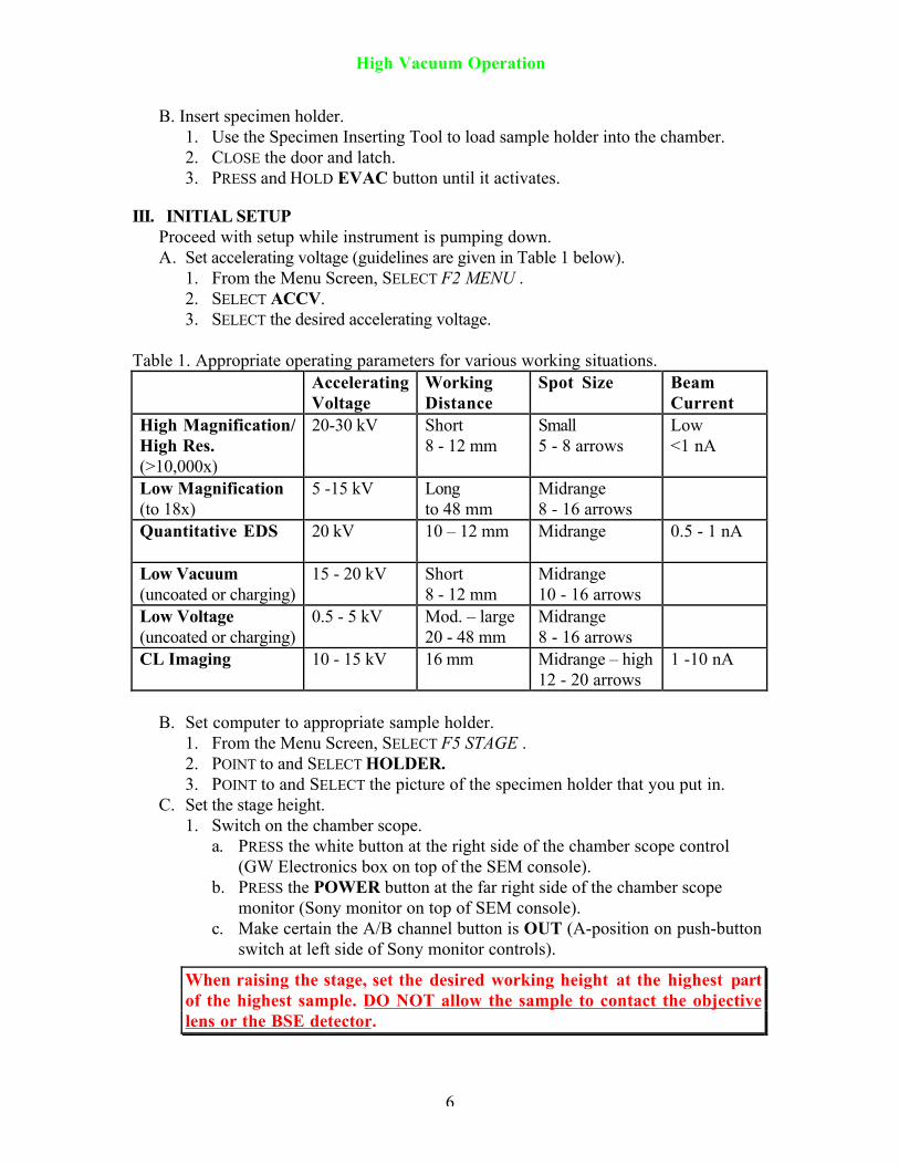
Table 1. Appropriate operating parameters for various working situations.AcceleratingVoltage
WorkingDistance
Spot Size BeamCurrent
High Magnification/High Res.(>10,000x)
20-30 kV Short8 - 12 mm
Small5 - 8 arrows
Low<1 nA
Low Magnification(to 18x)
5 -15 kV Longto 48 mm
Midrange8 - 16 arrows
Quantitative EDS 20 kV 10 – 12 mm Midrange 0.5 - 1 nA
Low Vacuum(uncoated or charging)
15 - 20 kV Short8 - 12 mm
Midrange10 - 16 arrows
Low Voltage(uncoated or charging)
0.5 - 5 kV Mod. – large20 - 48 mm
Midrange8 - 16 arrows
CL Imaging 10 - 15 kV 16 mm Midrange – high12 - 20 arrows
1 -10 nA
B. Set computer to appropriate sample holder.1. From the Menu Screen, SELECT F5 STAGE .2. POINT to and SELECT HOLDER.3. POINT to and SELECT the picture of the specimen holder that you put in.
C. Set the stage height.1. Switch on the chamber scope.
a. PRESS the white button at the right side of the chamber scope control(GW Electronics box on top of the SEM console).
b. PRESS the POWER button at the far right side of the chamber scopemonitor (Sony monitor on top of SEM console).
c. Make certain the A/B channel button is OUT (A-position on push-buttonswitch at left side of Sony monitor controls).
When raising the stage, set the desired working height at the highest partof the highest sample. DO NOT allow the sample to contact the objectivelens or the BSE detector.

High Vacuum Operation
7
2. Manually set the stage height using the joy stick.a. PRESS the T/Z button to change to the "Z" the function of the joystick.b. Raise stage by pushing joystick away from you (positive Y direction),
lower by moving joystick toward you (negative Y direction).c. On the chamber scope monitor, observe the position of the sample relative
to the bottom of the objective lens.d. PRESS the X/Y button to change back to the "X-Y" the function of the
joystick.D. Move the sample position to an appropriate place on the sample or holder.
(For the most part, beam saturation and alignment can be done anywhere on thesample. However, to avoid damaging the sample, it is recommended that setup bedone on the rim of the sample holder.1. TURN the MAGNIFICATION knob counterclockwise to the lowest
magnification.2. Make sure the X/Y button is lit on the keyboard.3. The Menu Screen should be on F5 STAGE menu.
a. Point and click the mouse on some part of the sample holder rim.b. A dialog box will appear. SELECT "Start" to move to the point.
IV. INSTRUMENT STARTUPYou may proceed with this section once "HT Ready" is displayed in the Status Panel.A. Filament saturation.
1. PRESS LSP1 button.a. ADJUST the BRT knob to approximately center the line on the monitor.b. As you reach filament saturation, it may be necessary to adjust both BRT
and CONT knobs to maintain the line within the middle portion of themonitor.
2. PRESS HT button. The FILAment light will flash until you begin heating thefilament.
3. PRESS the lower left corner of the Photo Panel to release the lid and access theFilament Panel.a. Slowly TURN the FILAMENT knob clockwise to heat the filament.b. TURN the knob past the false peak until the line profile no longer rises.
Leave the knob just at the point of saturation (Do not turn past 3:00o'clock).
4. PRESS TV2 button on keyboard.5. TURN magnification all the way down.
If the FILAment light begins flashing after you have reached saturationor if it never stops flashing, the filament is burned out. Notify the labmanager.

High Vacuum Operation
8
B. Current axis (gun) alignment).Note 1: You will need a sample area suitable for magnification up to 20,000x.
You can probably find a small milling mark or other discernible feature on thesample holder (bright spherical objects work best).
Note 2: This procedure brackets the most commonly used current range (from 8to 16). If lower spot size will be used, e.g. <8 for high resolution imaging,bracket gun alignment range from 1 to 8.
1. ADJUST the FOCUS knob (coarse focus) and initially focus at lowmagnification on the surface of the sample holder.a. Gradually increase magnification while focusing to find a small feature.b. At 20,000X, approximately center the object in the monitor.
2. PRESS SPOT SIZE button. Use CRS knob to set spot size to 8 (>>>>>>>>)on the Status Panel.
3. PRESS RESET button on keyboard.a. Refocus. (You will probably have to turn the magnification down to find
the object again).b. PRESS RESET button again and refocus if necessary.c. Repeat reset until there is no movement or change in focus.
4. Closely center object on the monitor using the joystick.a. Place left index finger on object at center of monitor and keep it there.b. ADJUST SPOT SIZE to 16 (>>>>>>>> >>>>>>>>).c. While keeping finger on object, PRESS SHIFT button on Filament Panel.
1) ADJUST X and Y gun alignment knobs on Filament Panel to re-centerobject under finger.
d. Observe object while turning SPOT SIZE back to 8.1) While turning spot size down, object may loop out from under finger
and return back. This is a function of the microscope itself and is ok.2) If object has shifted from center (under finger) repeat from step 4
above until object returns to within 0.5 µm of center.e. Set SPOT SIZE back to midrange (you can lift your finger off the screen
now!).f. PRESS SHIFT button off.
5. PRESS LSP1 button on keyboard to check gun tilt.a. ADJUST X and Y gun alignment knobs on Filament Panel to maximize
height of line profile on screen.b. Close Filament Panel lid using lower left corner of Photo Panel. Be careful
not to take a picture by pressing one of the Photo buttons.c. PRESS TONE button.
C. Objective aperture alignment.Aperture sizes are as follows: #1=20 µm, #2=30 µm and #3=100 µm1. PRESS TV1 button on keyboard.2. TURN MAGNIFICATION to 1,000-5,000x and center the monitor on a
clearly discernible object.3. PRESS WOBB button on keyboard and observe any apparent motion of
object.

High Vacuum Operation
9
a. If object moves around on screen, the objective aperture must be aligned(any apparent stretching of the object will be eliminated later)
b. Adjust aperture alignment control knobs (one at a time) until objectremains centered while wobbling in and out of focus.1) Side knob controls SW-NE motion.2) End knob controls NW-SE motion.
4. PRESS WOBB button off.D. Stigmation adjustment
Note: You will need an area of the sample holder that has fine details (a cluster ofbright, spherical objects is best).
1. PRESS D-MAG button on keyboard.2. Increase magnification to an appropriate level (5,000-20,000x).3. ADJUST the FOCUS knob (coarse focus) to best focus.4. PRESS COARSE button off, and carefully focus as well as possible.5. PRESS STIG button.
a. Adjust X and Y stigmation knobs one at a time until image becomes asclear and sharp as possible.
b. Readjust fine focus.c. Repeat until image is sharp and clear.
6. PRESS TONE button.E. Begin work on your sample.
1. Use joystick to move to your sample.2. Refer to other sections of the manual for other procedures.3. After completion of work, return to the next section below for shut-down
procedures.
High Vacuum Operation
10
V. INSTRUMENT SHUTDOWNA. Turn filament off.
1. Raise Photo Panel lid and TURN FILAMENT knob fully counterclockwise.2. PRESS HT button off.3. Close Photo Panel lid.
B. Return stage to exchange position.1. Turn on the chamber scope light and monitor if it is not already on.2. From the Menu Screen, SELECT F5 STAGE menu.3. SELECT "Exchange" from File List. Use “Low exchange” if large samples are in
the chamber.a. SELECT "Start."
Watch the sample on the chamber scope monitor. If the sampleappears that it might, for any reason, contact the BSE detector,immediately move the joystick in any direction to abort the move.
4. If necessary, set image mode to SEI.a. From the Menu Screen, SELECTF2 MENU.b. SELECT IMS and then option #1 SEI.
5. Wait for a few minutes for filament to cool before continuing.C. Remove sample holder.
1. PRESS and HOLD the VENT button until it activates.2. UNLATCH the door latch.3. Wait until VENT light stops flashing. Instrument will beep once (door may
open by itself before that!).4. Use the Specimen Inserting Tool to remove sample holder from the chamber.5. CLOSE the door and latch.6. PRESS and HOLD EVAC button until it activates.7. Remove sample holder from Tool by pressing rubber buttons on Tool handle.
a. Remove sample adapter from holder; return holder to shelf.b. Remove sample stubs from adapter; return adapter to shelf.c. Return Inserting Tool to drawer.
D. Secure the instrument.1. Turn down both JEOL monitors by turning two thumb knobs under each
monitor fully counterclockwise.2. PRESS SL3 button on keyboard.3. PRESS D-MAG button off.4. SET magnification to 300,000x.5. Turn off chamber scope and monitor.
E. Shut down computer.F. Fill out logbookG. Clean up around instrument and sample prep counter.
Low Vacuum Operation
11
OPERATION IN LOW VACUUM MODE
I. PRELIMINARY PROCEDURESA. Mount samples in the appropriate holder.
1. Securely mount the sample to a sample stub.a. Use carbon paint, carbon or double-sided Scotch tape, or Duco™ cement
to secure the sample to a sample stub.b. Modeling clay or aluminum foil may be used to prop up a sample in
holder.2. Secure the sample stub into the specimen adapter with a set screw.3. Place the adapter into the specimen holder and secure with one or more set
screws.Note: You will need to take special precautions if the sample protrudes more than
1 cm above the height of the specimen holder. Only experienced usersshould attempt to operate with samples taller than 1 cm.
B. Check condition of instrument.1. Turn up both JEOL monitors using thumb knobs under each monitor.2. On the Status Panel, check to see that the previous user has left the instrument
at the proper settings:a. The SEI detector should be enabled.b. Accelerating voltage is at 20 kV.c. Stage height is at Z=25 or greater.d. Stage X, Y, T and R should be at approximately 0.
Do not load a sample when the stage is less than 25 mm.
3. If any of the stage parameters are not as shown above, set stage to ExchangePosition.a. From the Menu Screen, SELECT F5 STAGE .b. SELECT "Exchange Position" from the file list (Use "Low Exchange" if large
samples will be introduced).c. SELECT START from the window to start the stage moving.
C. Check status of the keyboard:a. Joystick X/Y button is activated (it should be green).b. The TONE button is activated.c. COARSE focus button is activated.d. Beam BLANK button is NOT activated (not red).e. HT button is NOT activated.f. L(eft) screen freeze button is NOT activated.g. D-MAG button is not activated.
II. LOAD SAMPLESA. Vent the chamber.
1. PRESS and HOLD the VENT button until it activates.2. UNLATCH the door latch.
Low Vacuum Operation
12
3. Wait until VENT light stops flashing. Instrument will beep once (door mayopen by itself before that!).
B. Insert specimen holder.1. Use the Specimen Inserting Tool to load sample holder into the chamber.2. CLOSE the door and latch.3. PRESS and HOLD EVAC button until it activates.
C. Turn on the LV mode at this point for faster evacuation.1. Lift the plastic lid on the LV control and PRESS the white button.2. PRESS the AUTO button.3. Dial in the desired pressure on the CONTROLLER knob.
a. Start at a low number, e.g. 30 Pa, and try to image at this pressure.b. If charging is a problem, you may increase the pressure at any time by
pressing the Auto button and dialing in a higher pressure.c. The pressure reading on the vacuum gage will flash until that pressure is
achieved in the specimen chamber.
III. INITIAL SETUPProceed with setup while instrument is pumping down.A. Set accelerating voltage.
1. From the Menu Screen, SELECT F2 MENU .2. SELECT ACCV.3. SELECT the desired accelerating voltage.
a. Use 20 kV for most applications, including EDS analysis, at workingdistance 8-15 mm.
b. For greater working distance, increase accelerating voltage to 25-30 kV.B. Set computer to appropriate sample holder.
1. From the Menu Screen, SELECT F5 STAGE .2. POINT to and SELECT HOLDER.3. POINT to and SELECT the picture of the specimen holder that you put in.
C. Set the stage height.1. For low vacuum microscopy, a short working distance of 15 mm or less to the
top of the sample should be used (the upward limit of z is 8 mm).2. Switch on the chamber scope.
a. PRESS the white button at the right side of the chamber scope control(GW Electronics box on top of the SEM console).
b. PRESS the POWER button at the far right side of the chamber scopemonitor (Sony monitor on top of SEM console).
c. Make certain the A/B channel button is OUT (A-position on push-buttonswitch at left side of Sony monitor controls).
3. Manually set the stage height using the joy stick.
When raising the stage, set the desired working height at the highest partof the sample. DO NOT allow the sample to contact the objective lens orthe BSE detector.
a. PRESS the T/Z button to change to the "Z" the function of the joystick.
Low Vacuum Operation
13
b. Raise stage by pushing joystick away from you (positive Y direction),lower by moving joystick toward you (negative Y direction).
c. On the chamber scope monitor, observe the position of the sample relativeto the bottom of the objective lens.
d. PRESS the X/Y button to change back to the "X-Y" the function of thejoystick.
D. Move the sample position to an appropriate place on the sample or holder.(For the most part, beam saturation and alignment can be done anywhere on thesample. However, to avoid damaging the sample, it is recommended that setup bedone on the rim of the sample holder.1. TURN the MAGNIFICATION knob counterclockwise to the lowest
magnification.2. Make sure the X/Y button is lit on the keyboard.3. The Menu Screen should be on F5 STAGE menu.
a. Point and click the mouse on some part of the sample holder rim.b. A dialog box will appear. SELECT "Start" to move to the point.
Watch the sample on the chamber scope monitor. If the sample appears thatit might, for whatever reason, contact the BSE detector, immediately movethe joystick in any direction to abort the move.
IV. INSTRUMENT STARTUPYou may proceed with this section once "HT Ready" is displayed in the Status Panel.A. Filament saturation.
1. Switch off the chamber scope light.2. PRESS SPOT SIZE button.
a. Use CRS knob to set spot size to midrange on the Status Panel.b. PRESS TONE button.
3. PRESS LSP1 button.a. ADJUST the BRT knob to approximately center the line on the monitor.b. As you reach filament saturation, it may be necessary to adjust both BRT
and CONT knobs to maintain the line within the middle portion of themonitor.
4. PRESS HT button. The FILAment light will flash until you begin heating thefilament.
5. PRESS the lower left corner of the Photo Panel to release the lid and exposethe Filament Panel.a. Slowly TURN the FILAMENT knob clockwise to heat the filament.b. TURN the knob past the false peak until the line profile no longer rises.
Leave the knob just at the point of saturation (Do not turn past 3:00o'clock).
If the FILAment light begins flashing after you have reached saturation orif it never stops flashing, the filament is burned out. Notify the labmanager.

Low Vacuum Operation
14
B. Gun alignment.1. PRESS on the ON/OFF switch on the Keithley Picoammter. Range should be
set to “Auto”.2. SWITCH the MET/GND switch (little blue box behind column) to MET.3. TURN MAGNIFICATION to 300,000x.4. PRESS SPOT SIZE button. Use CRS knob to set spot size to 16
(>>>>>>>> >>>>>>>>) on the Status Panel.a. PRESS RESET button on keyboard.b. PRESS SHIFT button on Filament Panel.
1) ADJUST X and Y gun alignment knobs on Filament Panel to getmaximum reading on the picoammeter.
d. TURN SPOT SIZE back to 8.f. PRESS SHIFT button off.
5. PRESS LSP1 button on keyboard to check gun tilt.a. ADJUST X and Y gun alignment knobs on Filament Panel to maximize
height of line profile on screen.b. TURN SPOT SIZE to midrange on Status Panel.c. Close Filament Panel lid using lower left corner of Photo Panel. Be careful
not to take a picture by pressing one of the Photo buttons.d. PRESS TONE button.
C. Objective aperture alignment.Note: You will need to find a feature on the sample holder that has significant
contrast against the aluminum holder.1. PRESS SL1 button on keyboard.2. TURN MAGNIFICATION to 1,000-5,000x and center the monitor on a
clearly discernible object on the sample holder.3. PRESS WOBB button on keyboard and observe any apparent motion of
object.a. If object moves around on screen, the objective aperture must be aligned
(any apparent stretching of the object will be eliminated later)b. Adjust aperture alignment control knobs (one at a time) until object
remains centered while wobbling in and out of focus.1) Side knob controls SW-NE motion.2) End knob controls NW-SE motion.
4. PRESS WOBB button off.D. Stigmation adjustment
1. PRESS SL1 button on keyboard.2. PRESS D-MAG button on keyboard.3. Set magnification to an appropriate level (1,000-5,000x).4. ADJUST the FOCUS knob (coarse focus) to best focus.5. PRESS COARSE button off, and carefully focus as well as possible.6. PRESS STIG button.
a. Adjust X and Y stigmation knobs one at a time until image becomes asclear and sharp as possible (this is difficult in low vacuum).
b. Readjust fine focus and repeat if necessary.

Low Vacuum Operation
15
7. PRESS TONE button.E. Begin work on your sample.
1. Use joystick to move to your sample.2. Refer to other sections of the manual for other procedures.3. After completion of work, return to the next section below for shut-down
procedures.
V. INSTRUMENT SHUTDOWNA. Turn filament off.
1. Raise Photo Panel lid and TURN FILAMENT knob fully counterclockwise.2. PRESS HT button off.3. Close Photo Panel lid.
B. Return stage to exchange position.1. TURN on the chamber scope monitor and light.2. From the Menu Screen, SELECT F5 STAGE menu.
a. If tall samples are present, manually move the stage down until all samplesare well below from the objective lens.
b. SELECT "Low exchange” from the File List if large samples are in thechamber, otherwise SELECT "Exchange" from File List.
c. SELECT "Start."
Watch the sample on the chamber scope monitor. If the sampleappears that it might, for any reason, contact the BSE detector,immediately move the joystick in any direction to abort the move.
4. Wait for a few minutes for filament to cool before continuing.C. Remove sample holder.
1. PRESS and HOLD the VENT button until it activates.2. Lift the plastic lid on the LV control and PRESS the white button (it will go off
shortly).3. UNLATCH the door latch.4. Wait until VENT light stops flashing. Instrument will beep once (door may
open by itself before that!).5. Use the Specimen Inserting Tool to remove sample holder from the chamber.6. CLOSE the door and latch.7. PRESS and HOLD EVAC button until it activates.
D. Secure the instrument.1. Turn off the LV mode.
a. Lift the plastic lid on the LV control and PRESS the white button.2. Set image mode to SEI.
a. From the Menu Screen, SELECTF2 MENU.b. SELECT IMS and then option #1 SEI.
3. Turn down both JEOL monitors by turning two thumb knobs under eachmonitor fully counterclockwise.
4. PRESS SL3 button on keyboard.5. PRESS D-MAG button off.6. SET magnification to 300,000x.

Low Vacuum Operation
16
7. Turn off chamber scope and monitor.8. SWITCH the MET/GND switch (little blue box behind column) to MET.
E. Fill out logbook.F. Turn off computer.
Procedures
17
MICROSCOPE PROCEDURES
PRIMARY IMAGING
I. SECONDARY AND BACKSCATTERED ELECTRON IMAGINGA. The secondary electron (SE) detector can be used in any mode of operation
EXCEPT low vacuum.1. The SE detector will be automatically turned off and the backscattered
detector will be switched on in low vacuum operation2. To switch between detectors in high vacuum mode:
a. From the Menu Screen, SELECT F2 MENU .b. SELECT IMS.
1) SELECT the SEI (#1) detector for secondary electron imaging.2) SELECT the BSE Compo (#2) detector for compositional or
"shadowed" topographical backscattered electron imaging (BSE Topo[#3)] is used to emphasize the DIFFERENCES in topography ratherthan produce a topographic image).
3) SELECT AUX (#8) for cathodoluminescence imaging (see below).4) No other imaging modes can be activated from this menu.
B. The BSE detector can used in any mode of operation.1. During low vacuum operation, it is the ONLY image detector available.2. For collection of topographical images (especially in low vacuum mode), the
"shadow" detector must be switched on.a. From the Menu Screen, SELECT F2 MENU .b. SELECT BEIW.c. In the BEIW window, SWITCH SHADOW to ON.d. On the SHADOW ENHANCE slider, set the degree of topographic
enhancement (settings between 5 and 7 seem to work best).1) Higher values produce more topographic contrast, but darken the
image.2) Lower values result in less topographic contrast and brighter images.
3. For pure BSE images, e.g. working on polished thin sections, switch theshadow detector off.
4. SELECT scan speed SL1.
II. OPERATION OF THE CL DETECTORRead the introductory section for tips on how to use the CL detector.A. Setting up the SEM for CL work.
1. Mount the sample.a. Use polished, carbon-coated samples (probe sections or polished slabs).b. Mount your sample in the thin section holder as you would with a probe
section, or mount directly on an appropriate size aluminum sample stubwith carbon tape (don't forget to provide a conductive path from thesample surface).
c. The sample should not protrude above the rim of the aluminum sampleholder.

Procedures
18
2. Load the sample.a. Make sure that:
1) The stage is not tilted (T=0).2) Stage X, Y, and R should be at approximately 0.3) Stage height is at Z=25 or greater.4) The CL detector is withdrawn (large silver knob fully clockwise).
b. Vent the chamber as normal.c. Insert the sample into the SEM.d. Set sample height.
1) While the door is open, insert the CL mirror by turning the large silverknob on the luminescence detector counterclockwise. Turn the knobgently until it stops.
2) Watch while you move the stage upward until the sample surface isabout 1 mm below the mirror. The Z setting should now be around 15-17 mm depending on sample height.
Do not drive the stage into the mirror! !
3) Retract the mirror by turning the silver knob clockwise. The mirror isfully retracted when you come to a gentle "bump" and the knob willturn no farther.
e. Close the door and latch. Evacuate the chamber as normal.3. Setup the SEM.
a. Make sure the Chamberscope IR light is off.b. Check initial settings on the PA1 amplifier (Oxford Instruments box on
top of the SEM console):1) Gain = 5.02) Offset= 5.03) X100/X1000 switch in up (X100) position.4) Invert/Normal switch between Amplifier Overload light and Input
Overload light is set to the left (Normal image).5) The unit is switched off (green LED light should not be lit).
c. Set the accelerating voltage at 10 to 15kV (or less).B. Operation.
1. Bring up the beam as normal.a. Optimize the gun and column aligment for a spot size at midrange or above
(>>>>>>>> >>>>).
It is important to have the beam in optimum alignment for CL work—don'tshortcut this step! Refer to IV.B. through IV.D. in the HIGH VACUUMsection above.
2. Navigate to the area of interest on your sample.3. Obtain a focused good secondary electron image on the sample.4. Carefully insert the mirror.
a. Set the magnification to its lowest setting and scan rate to TV1.
Procedures
19
b. Rotate the large silver knob slowly counterclockwise while watching theSE image.1) If the SE image of the sample moves during insertion (mirror has
bumped the sample), retract the mirror, lower the stage slightly, andtry again.
2) At low magnification (<100x) you should be able to see the hole in themirror when it is fully inserted.
c. Center the hole in the mirror vertically in the SE image by finely adjustingthe large silver knob.1) The secondary electron image will be seriously degraded by inserting
the mirror. This is normal.2) Obtain a reasonable secondary electron image by adjusting SEM
contrast and brightness.3) Increase the magnification to a point where you can no longer see the
hole in the mirror.5. Acquire an image from the CL detector.
a. Turn on the power to the PA1 amplifier (black button at the lower right).b. Switch to the CL image.
1) From the Menu Screen, SELECT F2 MENU .2) SELECT IMS, then SELECT AUX (#8) from the IMS window.3) SELECT SL1 or SL2 on the keyboard.
Do not allow the detector to be flooded with too much light. If thechamberscope IR light is left on, the door opened with the PA1 left on, or ifsamples luminesce too strongly, the amplifier will switch off and the redoverload light will come on. Correct the problem before resetting theamplifier.
c. Carefully jog the stage up or down by 1 or 2 mm maximum to find thefocal point of the mirror. Look for an increase in brightness at the focalpoint.
d. The image contrast and brightness is controlled by:1) Gain and offset knobs on the PA1 amplifier.2) Increasing or decreasing beam current.
a) If image screen is flooded white, turn gain down or drop the beamcurrent. For extreme CL, set accelerating voltage to a lower kV.
b) If image screen is dark, turn gain up or try turning beam current up.For weakly luminescing samples, switch amplification factor toX1000 (use X100 for most things).
c) Set gain until an image of bright spots (pixels) can be seen on thescreen. Adjust offset down (usually) until individual pixels can beseen and they are not flaring or smearing into each other.
f. Use a slow scan for correct exposure.1) Use SL2 or SL3 on the JEOL to collect an image on the screen.2) To collect images on the Isis system, use the Slow scan with the dwell
set at 400 µs or greater. For persistent CL (phosphorescence), which

Procedures
20
will appear as streaks in the image, increase the dwell time to as high asnecessary (up to 6400 µs) to eliminate streaking.
3) It is best to use the smallest, or lowest resolution (Medium scan),image on the Oxford to set up the exposure, then switch to Fine orUltrafine scan to collect the final image.
g. For moving about your sample you will probably find it most convenientto retract the mirror, returning to SE or BSE imaging.1) Because the mirror blocks electrons from reaching the BSE detector,
BSE imaging cannot be used with the mirror inserted.2) Likewise, the mirror also blocks x-rays from reaching the EDS detector,
so it cannot be used with the mirror inserted.
Do not rotate or tilt the stage or move Z closer than 15 mm with the mirrrorinserted!
C. Shut off the CL detector and retract the mirror.1. Switch the PA1 amplifier off.2. Retract the mirror by rotating the large silver knob fully clockwise.3. If you are finished with the CL detector, return PA1 settings to initial values
(see section A.3. above)
Do not open the chamber without first turning the CL detector off!

21
OXFORD SYSTEM PROCEDURES
DIGITAL IMAGING
The Oxford Isis system consists of specialized programs that are accessed as programmodules selected from the control and database program (“Labbook”). The programsavailable are: X-Ray Analysis, Autobeam (digital image acquisition), Detector Control,Autostage (automated stage control), IMQuant (digital image analysis) and Notebook(report writing). From within X-ray Analysis, the available programs are Quant,SpeedMap, Quantmap, Linescan and Autocolumn. Cameo and Phase Measurement areavailable in Autobeam.
I . ELECTRON AND CATHODOLUMINESCENCE IMAGINGA. Start Isis imaging software.
1. Turn on the HP computer and monitor.a. PRESS any key (spacebar) to start the computer (Windows™ will load
automatically).b. If green or yellow light is on present at the lower right the of the monitor,
it is already on; otherwise turn monitor on at switch (lower right front).2. Start and setup Isis “Labbook”
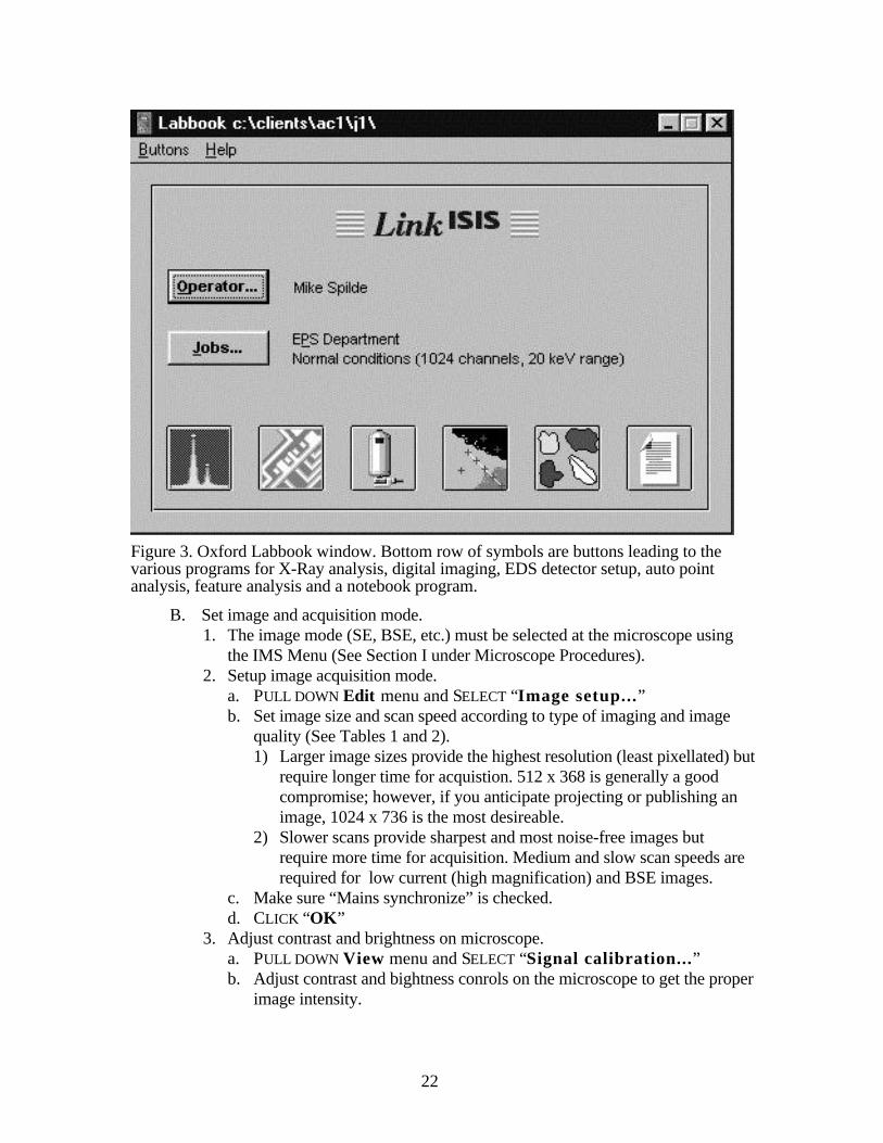
a. SELECT (double-click on) the “Link ISIS” shortcut icon from thedesktop.
1) After a short time, the “Welcome to Link ISIS” window will appear;SELECT your name from the list of operators.
2) CLICK the small blue labbook icon or double-click on your name.b. Next the “Labbok” window will appear (Fig. 3).
1) Your last job file will appear by default, but if necessary, change tothe appropriate job file or create a new one (see section c. below). Allyour spectra and images should be stored in your own job file--don’tuse someone else’s.
2) CLICK Autobeam button (second from left).c. To change or setup new jobfile.
1) CLICK JOBS. . . button.2) Double-click on one of your available job files or setup new.
a) PULL DOWN “Jobs” menu.b) SELECT “Create a new job...”c) PRESS “Yes” on the Job Creation dialog box.d) Type in Job Description and Client Name.e) PRESS “OK”3) Your job file is now available for use.
22
Figure 3. Oxford Labbook window. Bottom row of symbols are buttons leading to thevarious programs for X-Ray analysis, digital imaging, EDS detector setup, auto pointanalysis, feature analysis and a notebook program.
B. Set image and acquisition mode.1. The image mode (SE, BSE, etc.) must be selected at the microscope using
the IMS Menu (See Section I under Microscope Procedures).2. Setup image acquisition mode.
a. PULL DOWN Edit menu and SELECT “Image setup...”b. Set image size and scan speed according to type of imaging and image
quality (See Tables 1 and 2).1) Larger image sizes provide the highest resolution (least pixellated) but
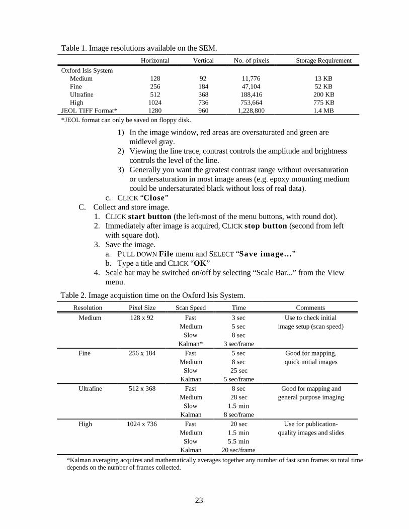
require longer time for acquistion. 512 x 368 is generally a goodcompromise; however, if you anticipate projecting or publishing animage, 1024 x 736 is the most desireable.
2) Slower scans provide sharpest and most noise-free images butrequire more time for acquisition. Medium and slow scan speeds arerequired for low current (high magnification) and BSE images.
c. Make sure “Mains synchronize” is checked.d. CLICK “OK”
3. Adjust contrast and brightness on microscope.a. PULL DOWN View menu and SELECT “Signal calibration...”b. Adjust contrast and bightness conrols on the microscope to get the proper
image intensity.
23
1) In the image window, red areas are oversaturated and green aremidlevel gray.
2) Viewing the line trace, contrast controls the amplitude and brightnesscontrols the level of the line.
3) Generally you want the greatest contrast range without oversaturationor undersaturation in most image areas (e.g. epoxy mounting mediumcould be undersaturated black without loss of real data).
c. CLICK “Close”C. Collect and store image.
1. CLICK start button (the left-most of the menu buttons, with round dot).2. Immediately after image is acquired, CLICK stop button (second from left
with square dot).3. Save the image.
a. PULL DOWN File menu and SELECT “Save image...”b. Type a title and CLICK “OK”
4. Scale bar may be switched on/off by selecting “Scale Bar...” from the Viewmenu.
Table 1. Image resolutions available on the SEM.
Horizontal Vertical No. of pixels Storage Requirement
Oxford Isis SystemMedium 128 92 11,776 13 KBFine 256 184 47,104 52 KBUltrafine 512 368 188,416 200 KBHigh 1024 736 753,664 775 KB
JEOL TIFF Format* 1280 960 1,228,800 1.4 MB
*JEOL format can only be saved on floppy disk.
Table 2. Image acquistion time on the Oxford Isis System.
Resolution Pixel Size Scan Speed Time Comments
Medium 128 x 92 Fast 3 sec Use to check initialMedium 5 sec image setup (scan speed)
Slow 8 secKalman* 3 sec/frame
Fine 256 x 184 Fast 5 sec Good for mapping,Medium 8 sec quick initial images
Slow 25 secKalman 5 sec/frame
Ultrafine 512 x 368 Fast 8 sec Good for mapping andMedium 28 sec general purpose imaging
Slow 1.5 minKalman 8 sec/frame
High 1024 x 736 Fast 20 sec Use for publication-Medium 1.5 min quality images and slides
Slow 5.5 minKalman 20 sec/frame
*Kalman averaging acquires and mathematically averages together any number of fast scan frames so total timedepends on the number of frames collected.

24
II. EXPORTING DIGITAL IMAGES.
Digital images are saved in Oxford’s image format and must be converted to tiff orbitmap format and exported before they can be read by other image processing or printingprograms.
A. Open the image to export.1. Scale bar may be switched on/off by selecting “Scale Bar...” from the
View menu.a. Note that once the scale bar is added to an exported image, the bar and its
text cannot be manipulated, it becomes part of the image.1) An alternative to the less-than-nice-looking Oxford scale bar is to
export 2 images, one with a scale and one without.2) A scale bar of your liking can then be added to the unscaled in a more
functional program, such as Photoshop, using the scaled image forreference.
b. A scale can also be calculated from the formula L = 130/Mwhere L is image width (in mm) and M is magnification.
B. Export the image in either a TIFF format or BMP format.1. PULL DOWN File menu and SELECT “Export image...”2. In the dialog window, select the file destination (a folder outside of the
current Oxford folder that you are in).a. For ftp download or upload, select D:\!Downloads and select a file.b. For direct transfer to Zip-disk, select drive H.
3. Enter a file name, 8 characters or less (the .TIF or .BMP extension willautomatically be added.
4. CLICK “OK”
25
X-RAY ANALYSIS
The X-ray analyzer provides access to the EDS system for X-ray collection.Available from the analyzer are programs for auto-identification of peak, quantitativeanalysis, normal and quantitative EDS mapping, linescans, and beam control for automatedanalysis.
I . QUALITATIVE EDS ANALYSISA. Start Isis software and select your job file (See Section I.A. under Digital
Imaging).B. Set process time and acquisition time.
1. PULL DOWN Edit menu and SELECT “X-ray setup...”2. Type in acquistion time (default is 50 seconds).3. Check “Acquistion Preset” window for the process time used.
a. For fast acquisition but low resolution (Process Time 1), PRESS the“Optimum” button.
b. For best resolution of light elements (Process Time 6),PRESS the “BestResolution” button.
c. If quantitative analysis will be proformed, CLICK the “More...” buttonand select Process Time 4 form the pull-down menu
4. CLICK “OK”C. Select target and begin acquisition.
1. Place the electron beam on the target area by one of these methods:a. Move stage to the area of interest and zoom the magnification (e.g.
100,000x or greater),b. Collect an image on the SEM on the right-hand CRT.
1) From the Menu Screen, SELECT F2 MENU .2) SELECT EDX and drag the cursor cross with the left mouse button
depressed to the point of interest.3) SELECT SET to position beam on point; select again to relaese.
c. Collect an image with the Oxford Autobeam software.1) CLICK the left mouse button with the curser on the image at the point
of interest.2) Release beam when finished by clicking on right mouse button.
3. CLICK the round button on the analyzer button bar to begin acquistion.4. Use ?-button to find and label peaks.
D. Exporting Spectra1. To export as a graphic plot:
(Note: the TIFF export under the File Menu copies the solid-color spectrummay be problematic for some graphics software.)a. CLICK printer button.b. PULL DOWN File menu and SELECT “Export as TIFF (line
spectrum”c. Select destination and enter file name; CLICK “OK”
2. To export as an ASCII file:

26
(Note: this method produces a comma separated text file of the spectrum witha header. There are 1024 data points in 5 columns. It can be read by Excelbut works best with the freeware program Desktop Spectrum Analyzer fromNIST.)a. PULL DOWN File menu and SELECT “Spectrum Conversion”
1) SELECT “Conversion Type ...”2) CLICK the EMSA/MAS button and CLICK “OK”.
b. PULL DOWN File menu again and SELECT “Export”c. Select destination and enter file name; CLICK “OK”
II. QUANTITATIVE ANALYSIS
III. X-RAY MAPPINGA. X-Ray Map SetupB. Map Data Analysis
1. Contrast and brightness adjustments2. Map mixing and overlays3. Phase Measurement
IV. X-RAY LINESCANS
V. AUTOMATION
IMAGE AND DATA ANALYSIS
I. X-RAY MAP ANALYSISA. Basic Map AnalysisB. Cameo AnalysisC. Phase Map Analysis
Open AutobeamPress Cameo buttonSelect open image from File menu to open speed map or quantmap data.Select SE/BSE image (must select one)Hold Ctrl key and select 2 or 3 x-ray maps• Selecting 2 maps results in X-Y plot of 2 colors with lower 2 plotted on X-axis
and higher 2 on Y axis.
• Selecting 3 maps results in ternary plot of 3 colors lowest 2 is assigned to red in
lower right apexNext 2 assigned green at upper apexHighest 2 assigned blue at lower left apex
Press Phase Map button an Open File dialog windowPress the triangle button on the Autobeam window (A ternary scatter diagram will
be plotted in the Phase measurement window. The various phases should
27
appear as groups of clusters. If an x-ray map has low counts, empty diagonalareas or lines will appear on the plot.
Select 1st phase, define a name (if desired) Define phase by clicking left mousebutton on ternary diagram and draw a series of line segments (hold left mousebutton and draw) around phase or cluster of interest. Double click to enclosephase completely. Area % of that cluster will be displayed.
To add a new phase click on Phase button in Area Measurement window. Definename and outline phase. Up to 8 phases may be defined.
To change phase color, click on color box in Phase Measurement window.
It is useful to identify all phases in a map area first, then paint each phaseindividually by selecting the phase name then press Paint button to identify andpaint just that phase in the autobeam window.
Once phases are defined, named, etc. use the Paint All button to paint the Autobeamwindow with the defined phase colors. Note: if white saturated areas arepresent in the BSE image (e.g. from high-2 phases), it may be necessary toopen the image first and lower contrast and brightness slightly (with Cameobutton off) before starting this process. Otherwise the colors do not show up inthe white areas of the image.
Use Measure button to print phase proportion data. To print graphical phase map,hit Copy button to save to clipboard and paste as picture into a program such asWord or a graphics program (can also be saved as clipboard File .CLP).
II. IMQUANT

28
APPENDICESA. General Information
I. Calibrate stage to sample height(Focus at the top or highest point of sample.)1. Clear lens by pressing Reset OL button (Refocus if necessary).2. Enter command: AFT -OFF [Rtn] (turns off auto focus).3. Enter command: AFC-I [Rtn] (initialize stage).4. Enter command: WD [Rtn] (set working distance) .
a. Displays WD without decimal pointb. Use coarse and find focus to set reading to 200.c. Press “E.”
5. Clear the lens again.6. Use joystick to set mechanical Z to focus
a. Press T/Z button.b. Move joystick up or down to bring sample into focus.
7. Enter command: Stage - IZ [Rtn] (sets stage to WD height, which shouldnow be 20 mm).
II. Load Current Jump1. If the load current in the status monitor window should suddenly jump
above 100 uA, it MUST be reset or the filament will burn out.2. Press command F1, type: “Bias”, and hit Return.
a. The status monitor will display:
cmd>bias E/I/D ####
XXuA
3. Note the hexidecimal number in the upper right.4. Turn focus knob one or two clicks to the right and then back to where it was
(hexidecimal number should change and then return to original number)5. Hit “E” to exit.