jd 900f to lexion - headsight · 2017-12-06 · • qp0-ca12-31q (single point equipped heads) •...
TRANSCRIPT

Conversion Manual09040123a
JD 900FTOLEXION
HEADSIGHT.COM | 574.546.5022


i
Copyright Headsight, Inc. 2017
About Headsight
Headsight Contact InfoHeadsight, Inc. 4845 3B Road Bremen, IN 46506 Phone: 574-546-5022 Fax: 574-546-5760 Email: [email protected] Web: www.headsight.com
Technical AssistancePhone: 574-220-5511
About this Manual
How to use this manualThe instructions in this manual are in the order that they should be completed for new installations. Complete all applicable instructions in each section before proceeding. Note that some sections are labeled to indicate they only apply to certain machines or applications. An index is available in the front of the manual to help find technical information for previously installed systems.
This icon designates information of which you should take note.
This icon indicates a special tool needed for a given task.
This icon designates an important instruction.
DisclaimersHeadsight®, Horizon®, Pinpoint®, Insight®, Foresight®, Feathersight® Truesense™ and Truesight® are trademarks of Headsight, Inc. All other trademarks are property of their respective owners.
SuggestionsIf you have any suggestions to improve this manual please call 574-546-5022 or email [email protected].
Headsight’s products are protected by one or more of the following US Patents 6202395, 6833299, 7310931, 7647753 and other patents pending.

ii
Table of ContentsAbout Headsight ��������������������������������������������������������������������������������������������� iAbout this Manual ������������������������������������������������������������������������������������������� iInstallation �������������������������������������������������������������������������������������������������� 1
Header Type Identification ����������������������������������������������������������������������������� 1DAM Headers �������������������������������������������������������������������������������������������� 1Potentiometer Headers �������������������������������������������������������������������������������� 1
Components ����������������������������������������������������������������������������������������������� 2Multilink and Valve Mounting �������������������������������������������������������������������������� 3
For Singlepoint equipped heads ��������������������������������������������������������������������� 3For Multi-point equipped heads ��������������������������������������������������������������������� 3
Interface Box Mounting���������������������������������������������������������������������������������� 3Header Connection �������������������������������������������������������������������������������������� 4
For Multipoint equipped heads ���������������������������������������������������������������������� 4For Singlepoint equipped heads ��������������������������������������������������������������������� 4
Multilink Connection ������������������������������������������������������������������������������������ 5Reel Enable Connection ��������������������������������������������������������������������������������� 5Solenoid Connection ������������������������������������������������������������������������������������ 5
Calibration ��������������������������������������������������������������������������������������������������� 6Insight Calibration ��������������������������������������������������������������������������������������� 6
Initialize Insight ���������������������������������������������������������������������������������������� 6Calibrate Insight ���������������������������������������������������������������������������������������� 6Standard Calibration ����������������������������������������������������������������������������������� 6
Combine Calibration ������������������������������������������������������������������������������������� 7Calibration: 4/500 Series, 600F/FD Headers ������������������������������������������������������ 7Calibration: 6/700 Series ����������������������������������������������������������������������������� 8
Settings ������������������������������������������������������������������������������������������������������� 9Insight Settings ������������������������������������������������������������������������������������������� 9
Tilt Sensitivity ������������������������������������������������������������������������������������������ 9Tilt Balance ���������������������������������������������������������������������������������������������� 9
Combine Settings ����������������������������������������������������������������������������������������104/500 Combines ���������������������������������������������������������������������������������������106/700 Series ��������������������������������������������������������������������������������������������11
Operation ���������������������������������������������������������������������������������������������������12AHC Operation: All Combines��������������������������������������������������������������������������12
Overview ����������������������������������������������������������������������������������������������������13Insight® Navigation ��������������������������������������������������������������������������������������13
How to Navigate ����������������������������������������������������������������������������������������13Meaning of Status Light �������������������������������������������������������������������������������13Screen Contrast Adjustment �������������������������������������������������������������������������13Resetting Insight® to Defaults �����������������������������������������������������������������������14Updating Insight® Software with USB Drive �������������������������������������������������������14
Advanced Information ������������������������������������������������������������������������������������15Theory of Operation ������������������������������������������������������������������������������������15

iii
Basic Requirements �������������������������������������������������������������������������������������15Adjusting Sensors ���������������������������������������������������������������������������������������16Reading Voltages ����������������������������������������������������������������������������������������17
Before You Start ���������������������������������������������������������������������������������������17On the Insight® Box : Sensor Voltages ��������������������������������������������������������������17On the Insight® Box : Output Voltages ��������������������������������������������������������������17
Reading Voltages: Combine ����������������������������������������������������������������������������1812V Power Test ������������������������������������������������������������������������������������������18Wiring and Diagrams �����������������������������������������������������������������������������������19
Header Adapter Harness (-31Q shown, -31J similar) ��������������������������������������������19Multilink ������������������������������������������������������������������������������������������������20Header Adapter Schematic (-31J, Part 1) ����������������������������������������������������������21Header Adapter Schematic (-31J, Part 2) ����������������������������������������������������������22Header Adapter Schematic (-31Q, Part 1) ���������������������������������������������������������23Header Adapter Schematic (-31Q Part 2) ����������������������������������������������������������24Multilink Diagram (Part 1)���������������������������������������������������������������������������25Multilink Diagram (Part 2)���������������������������������������������������������������������������26Header Multilink Mechanical ������������������������������������������������������������������������27
Diagnostics �������������������������������������������������������������������������������������������������28Troubleshooting by Symptom �������������������������������������������������������������������������28Troubleshooting by Insight® Error Codes �����������������������������������������������������������33
Parts ���������������������������������������������������������������������������������������������������������41STATEMENT OF LIMITED WARRANTY �����������������������������������������������������������������42

1
Installation
Installation
Before working under header always:
1. Perform all combine and header manufacturer safety precautions for servicing header.
2. Insert stop to prevent movement of header.
3. Turn off combine and remove key from ignition.
4. Set combine parking brake.
5. Disconnect all drive shafts from the header.
Header Type Identification
There are 2 different types of AHC used on these combines. This system ONLY works for heads equipped with potentiometer height and lateral tilt sensors. If your head has the DAM box, you MUST upgrade the header to potentiometer first. Contact Headsight.
DAM Headers• Has a 16 pin combine connection• Has the rectangular green “box” mounted on the
right end of the sensing cross rod
Potentiometer Headers• Has the 31 pin plug combine connection
• -31J shown• Has a horizontal linkage and pot connected to the
right end of the sensing cross rod• Any head already converted to single point
• -31Q

2
Installation
Components
1. Multilink• CA500MLHYD• Required to allow connection to the combine
2. Hydraulics, Dual Valve Assm. kit• HT9002• Required to control the hydraulic functions on the
header to the combine. See valve-specific manual. • Also Includes the Reel Flow fittings
3. Insight• INSIGHT• Converts the AHC system on the header to the
Lexion combine.
4. Header Adapter Harness• QP0-CA12-31Q (single point equipped heads)• QP0-CA12-31J (Multi point equipped heads)• This harness is installed on the Header, between
the Insight, Lexion multilink, valve assm, and the JD header connection. For connector details, see “Wiring” in the Appendix

3
Installation
Make sure the cable routing is done so no wiring can bind or pinch. Tie up all loose cabling. Properly installed wiring is the most critical aspect of a trouble-free installation. For harness details, see Wiring.
Multilink and Valve Mounting
1. Mount the Headsight provided Lexion Multilink assembly on the header. • Shown with combine connected• Photo shows one suggested mounting position
2. Install the Reel Flow couplings into the Multilink (500-700 series only)
3. See the Specific Installation Guide for the Lexion Dual Valve assembly for details on the next steps.
4. Mount the hydraulic valve assembly to the head.
5. Route the pressure and tank hoses from the valves to the multilink.
For Singlepoint equipped heads6. Disconnect the smaller hoses from the JD single point and connect them to the valve assembly as
shown in the Dual Valve Assembly
7. Disconnect the Reel Drive hoses from the JD single point and connect them to the Reel Flow couplers.
For Multi-point equipped heads8. You will need to manuafacture hoses from the OEM JD multipoint hose fittings to the Lexion valve &
multilink assemblies
Interface Box Mounting
9. Install Insight box at rear of header within reach of feederhouse electrical connection on combine and mark mounting hole locations.
10. Secure box to header. • Drill mounting holes using ¼” drill bit• Use provided button head bolts• Box must be within reach of the header electrical
connector
11. Connect the 24 pin connector on the adapter Header harness to the Insight box using an Allen wrench.
If Insight Box does not power up after completing full installation section, check that Y401 is connected to correct port on multilink, and see Advanced Info, 12V Power Test.

4
Installation
Header Connection
For Multipoint equipped heads1. Connect the Adpater plug to the existing header plug
For Singlepoint equipped heads2. Remove the C clip holding the OEM header electrical
connector in the JD single-point plate.
3. Remove the connector from the plate, and press fit the two loose connector bodies together. Secure with the HT2259 bracket and zip ties.

5
Installation
Multilink Connection
1. Connect Insight™ header harness to header side of multilink block.• The plug marked Y410 should connect to
receptacle VS1• The plug marked Y401 should connect to
receptacle VS2• Y424 (16 pin Round) is not used with the 900F
heads
2. Connect Y111 and Y112 (Lights) together.
3. Connect Y407 and Y408 (Valve Functions) together.
Reel Enable Connection
This step is only applicable to Multilink assemblies provided by Headsight®.
1. To Enable reel drive flow, connect the mating 1p Weatherpack connectors, Y517 & Y518.
Solenoid Connection
1. There are two sets of solenoid connections, Reel Lift & Reel F/A (shown). Follow the steps below to correctly attach them.• Connect Y411 to the Reel Lift Solenoid• Connect Y412 to the Reel Lower Solenoid• Connect Y413 to the Reel Fore Solenoid• Connect Y414 to the Reel Aft Solenoid• If any function acts in reverse, swap the connections
at the solenoids.
VS1
VS2

6
Calibration
Calibration
Insight Calibration
Initialize Insight
These steps must be performed the first time the Insight box is powered up and each time it is reset. They do not need to be redone each time the Insight box is calibrated.
Refer to “Insight Overview” for basic Insight operation information.
1. Connect all wiring to the Insight box and combine.
2. Start the combine.
3. Chose “English”, “Lexion”.
4. For ALL flex head conversions, choose Lexion 600/700 combine (even if you are running a 400 or 500 series.)
5. Choose the number of height sensors.• For JD 900F w/ Contour Master sensors, choose 3
Calibrate Insight
When you initialize Insight, you will be led directly to this calibration routine. If you wish to recalibrate at any other time – choose “>>Perform Calibration” on the Insight main menu.
Standard Calibration1. Park the combine on a level and smooth surface.
2. Follow on-screen instructions.• “Raise Header” - Press Enter
• Raise the head high enough that NO sensors touch the ground.• Voltages should typically be in the 3.0-4.5V range
• “Lower Header” - Press Enter• Lower the head ALL the way down onto the skids• Voltages should typically be in the 0.5-2.0V range• Each sensor must change at least 1.0V

7
Calibration
Combine Calibration
Before calibrating the combine, make sure the header type is chosen correctly. See Settings>>Header Type Settings.
Calibration: 4/500 Series, 600F/FD Headers
This section applies to ALL 400 and 500 combines when operating a Flex Head in Flex mode.
1. Start Combine.
2. Make sure that the Headsight Bypass harness is either not installed, or is disconnected from the header harness and has the Y402J jumper in place.
3. Adjust the CAC setting.
• Choose on the harvest display – Press OK• Choose “Header” – Press OK• Choose “Sensitivity CAC” – Press OK• Adjust setting as suggested for a flex platform in the Lexion Owner’s Manual. Increasing the setting
should weight height over tilt
4. Raise head almost up, and speed up motor.
5. Choose “Cutt. Height Limits” – Press OK.
6. Follow on-screen instructions. (If head drops too fast, see Combine Settings. • Raise header• Lower header
7. After calibration, the right bar graph (feeder position) should read “empty” to “full” as the head is moved full stroke.
8. After calibration, the left graph should read:• Nearly “empty” with the head all the way down hard• Nearly “full” as the cutterbar just leaves the ground
9. If the graphs operate as suggested, the header sensors are working properly and the calibration is good.

8
Calibration
Calibration: 6/700 Series
To insure a proper calibration, make sure your combine has the latest Lexion recommended software and the feeder to header latching mechanism is tight with minimal play. See Appendix for more information.
1. Start Combine.
2. Use the Scroll knob and ESC to navigate the menus as shown:
3. Get to the HHC “Learning End Stops”
• Choose on the main display – Press the Scroll knob to OK
• Choose – Press OK
• Choose – Press OK
• Choose – Press OK
4. The screen should read “Start learning procedure with “OK”.
5. Follow on-screen instructions.
6. You may also wish to calibrate other relevant items such as “Lateral Float End Stops” and “Reel End Stops”. See your Lexion Owners Manual.
7. Also adjust working position to about 50%.
8. After calibration, the right bar graph (feeder position) should read 0-100 as the head is moved full stroke.
9. After calibration, the left graph should read:• 0 with the head all the way down hard• 50 as the header frame begins to lift off the ground • 100 as the cutterbar just leaves the ground• 0-49 is the header lift pressure• 50-100 is the header AHC sensors
10. If the numbers on the graphs are close to this, the calibration is good.
OK ESC

9
Settings
Settings
Insight Settings
Tilt Sensitivity1. To change this setting go to >>Settings>>Tilt Sensitivity in the Insight™ box.
• Default setting is 50.
2. Adjust combine Tilt Sensitivity first (when available.)
3. If the head is to jumpy from side to side:• Decrease sensitivity
4. If you would like the head to be more responsive:• Increase sensitivity
5. Press Enter to save value
Tilt Balance1. To change this setting go to >>Settings>>Tilt Balance in the Insight™ box.
• Default setting is 100
2. Make certain ALL other possible causes of head running out of level are eliminated first:• Insight/sensors not calibrated on flat level surface• Combine not calibrated on same surface as Insight• Header float not equal across head. Cutterbar should move the same travel at both ends.
3. If the head will still not run level:• Increase value to tilt head to right. • Decrease value to tilt head to left. • Press Enter to save value
4. This setting must be reset to 100 every time before doing a combine header calibration.

10
Settings
Combine Settings
Properly setting the combine is essential to having responsive header control. You should become very familiar with these steps.
4/500 Combines1. Perform “Cutting Height Limits” calibration before attempting fine tuning.
2. Set CAC setting.• For On-Ground operation of a flex head, do not install the Pressure Bypass.
• Adjust the CAC to an appropriate setting exactly as if you were operating a Lexion header (see Lexion Owner’s Manual).
• Choose on the harvest display – Press OK.• Choose “Header” – Press OK.• Choose “Sensitivity CAC” – Press OK.
• Adjust setting as suggested for a flex platform in the Lexion Owner’s Manual. Increasing the setting should weight height over tilt
• Always redo “Cutting Height Limits” calibration after changing Sensitivity CAC. Insight must be in >>Setup >>Combine Cal Mode
4/500 High Speed Drop Rate
1. Use the high speed drop rate valve adjustment knob on the main valve block.• Turn OUT (counterclockwise) to slow down, IN (CW)
to speed up• If the speed is to fast – hunting will occur• If the speed is to slow – the system will not be
responsive enough
2. Common range is 8-10 seconds from header full up to full down in automatic mode.

11
Settings
6/700 Series
Set the high speed drop rate as high as you like without causing head “hunting”. If the head “hunts”, decrease the drop rate. You may need to set this before calibration if it is too fast.
1. Perform “Learning End Stops” calibration before attempting fine tuning.
2. Start Combine.
3. Use the Scroll knob and ESC to navigate the menus as shown:
4. Get to the HHC “Sensitivity CAC”.
• Choose on the main display – Press the Scroll knob to OK
• Choose – Press OK
• Choose – Press OK
• Choose – Press OK
5. All Settings have a range of -50 to +50.
6. “Cutting Height Adjustment” is actually height sensitivity. It should be adjusted just below the point the head will “hunt”.
7. Adjust the “Lateral leveling” to increase/decrease lateral response. It should be adjusted just below the point the head will “rock” side to side.
8. Set “fast manual raising” to 5-6 seconds Full down to full up.
9. Set “fast manual lowering” to 8-10 seconds full up to full down.
10. Set “Automatic drop rate” slow enough to eliminate “hunting”.
11. Suggesting starting values are shown in the picture. • Your values may vary• See your Lexion Owner’s manual for more information

12
Operation
Operation
AHC Operation: All Combines
Operate the Headsight system exactly like you would use a Lexion system. Further details may be found in the combine operator’s manual.
1. Engage header and separator clutch (700 shown, 400-500 similar)
2. Choose desired cutting height setpoints.• Lower the head to the desired cutting height
• Must be within the sensor travel range• Press and hold the “Left Side” button until the caret
resets to point to the top of the dark bar in the Left graph (Active Header Height)
• Tap button once and redo above to set 2nd position.
• The “greyed” caret is selected• To set a higher “feeder position”, press and hold the
“Right Side” button until the caret resets to point to the top of the dark bar in the Right graph (feeder Position)
• Tap button once and redo above to set 2nd position.
3. Press left side of header raise/lower button to enter active HHC. Press again to switch to 2nd setting.• The Left Side button (arrows to dot) is Active Header
Height (AHC). It should be used for all heads with height sensors on the head
• The Right Side button (arrows to lines) is “Feeder Position” (Return to Cut or RTC.) It should be used only for heads with NO height sensors, or to raise the head to a preset height for turning, etc.

13
Overview
Overview
Insight® Navigation
How to NavigateWhen in a menu (selection arrow appears to left side)
• Enter: chooses the selected menu choice• Esc: backs up one menu level• Up: moves up within the menu choices displayed • Down: moves down within the menu choices displayed
When in a screen which allows setting of parameters• Enter: backs up to last menu level AFTER saving• Esc: backs up to last menu level without saving• Up: increases the value• Down: decreases the value
Meaning of Status LightSolid Green:
• System is operating• No errors detected
Solid Red:• System is NOT operating• No height or tilt signals are sent to combine• You have changed settings which require calibration of Insight, are currently in a menu which will
force a calibration if you make any changes, or are in calibration mode
Solid Green with Flashing red:• System is operating• An error has been detected• Repair problem then clear errors
Flashing Red:• System is operating• A sensor has been ignored• See note in Troubleshooting by Error - ER16• Repair system - Recalibrate Insight
Screen Contrast AdjustmentTo increase contrast:
• Press and hold Esc +• Press Up to increase contrast (while holding Esc)
To decrease contrast:• Press and hold Esc +• Press Down to decrease contrast (while holding Esc)

14
Overview
Resetting Insight® to DefaultsTo reset all settings hold + for 5 seconds:
• Press and hold ESC then• Press and hold Enter while holding ESC• Hold both for 5 seconds
Updating Insight® Software with USB Drive
Updating software may cause the Foresight option to be disabled. If you have purchased Foresight, contact Headsight before updating software.
1. You will need:• USB drive• Means of loading USB Stick (computer with USB)
2. Load USB drive with new software files• Place insightf.hex in the root directory of USB drive (ex. E:\insightf.hex) • Do not change file names
3. If you do not have the new files you may• Download updated software from www.headsight.com • Order pre-loaded USB drive from Headsight, Inc.
4. Remove cap from USB on front of Insight controller
5. Insert USB drive card into USB slot on front of Insight
6. Power Insight• Turn on key switch
7. Wait for software to download• Yellow light will blink while download is in progress• Green light will turn on solid when download is complete
8. Verify update is successful• Go to >>About Insight>>Software Version and read software version number
9. Remove USB drive
10. Install cap on USB on front of Insight controller
11. Remove power from Insight• Turn off key

15
Advanced Info
Advanced Information
Theory of Operation
A review of the following points will help the service technician to understand the complete system which will help when diagnosing specific problems.
1. Each sensor returns a variable voltage depending on its height.• High height = high voltage (approximately 4 volts)• Low height = low voltage (approximately 1 volt)
2. Each sensor has 3 wires:• 5V power• Ground• Signal returned to the combine
• Varies between approximately 1.0 and 4.0 volts
3. The voltages the combine sees are exactly like what it would see with an OEM system. All existing combine controls and settings may be used.
Basic Requirements
If any sensor does not meet the requirements below you must correct it (to meet the requirements) and then recalibrate. See the header manual for sensor adjustment instructions. Each sensor must meet basic requirements for the combine to accept the calibration.
1. Signal must always be between .3 and 4.7 volts.
2. Signal must change more than 1.0 volts from raised to lowered position for each sensor.
16
Advanced Info
Adjusting Sensors
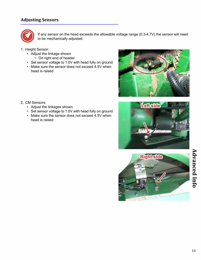
If any sensor on the head exceeds the allowable voltage range (0.3-4.7V) the sensor will need to be mechanically adjusted.
1. Height Sensor: • Adjust the linkage shown
• On right end of header• Set sensor voltage to 1.0V with head fully on ground• Make sure the sensor does not exceed 4.5V when
head is raised
2. CM Sensors: • Adjust the linkages shown• Set sensor voltage to 1.0V with head fully on ground• Make sure the sensor does not exceed 4.5V when
head is raised
Right side
Left side

17
Advanced Info
Reading Voltages
Before You Start
The Insight box can display both the input voltages it receives from each sensor and the output voltages it is sending to the combine.
Sensor voltage = Insight box input voltage Insight box output voltage = Combine sensor input
On the Insight® Box : Sensor Voltages1. From main menu, go to >>Diagnostics>>Disp Sensor
Voltages.• This shows real-time voltage coming from each sensor
2. For more information about sensor history and status see >>Diagnostics>>Detailed Diagnostics>>(parameter of interest.)
• Sensor = signal from sensor in volts• Max = the maximum voltage sent to Insight box from
sensor since last calibrated• Min = the minimum voltage sent to Insight box from sensor since last calibrated• Enabled = is this sensor enabled to control height? Yes or No• SetH = the “header raised” voltage set-point recorded during calibration• SetL = the “header lowered” voltage set-point recorded during calibration• Reversed = is the polarity of this sensor reversed? Yes or No
On the Insight® Box : Output Voltages3. From main menu, go to >> Diagnostics>>Detailed
Diagnostics>> (parameter of Interest). • This shows voltage being sent to the combine
4. Left or Right Height Out = X.XVolts:• 1V with head fully lowered• 4V with head raised
Insight box scales voltages received to what combine needs to function
Sensor Voltages
L LC CTR RC R0.0 0.0 0.0 0.0 0.0
Left Sens =0.00VMax=0.00V SetH=5.00VMin=0.00V SetL=0.00VEnabled=N Reversed=N
Pressure/aux Sensor Left Height OUTPUT Pressure Height OUT Right Height OUTPUT
Left Height OUTPUT
=2.0V

18
Advanced Info
Reading Voltages: Combine
1. You must have a Service Tool plugged into the Diagnostic ports to read voltages on a Lexion combine
2. To determine if the sensor voltages are getting to the combine, watch the Left bar graph on the display while raising and lowering the header. See the appropriate “Combine Settings” section for details.
12V Power Test
Complete the tests below to determine if you need to do the update. (Update should be very rare.)
1. Turn on engine. Make sure the Roading switch is in field mode.• If the Insight box turns on• You do not need to install the power wire • Go to next section
• If the Insight box does not turn on• Make sure that Y401 on the adapter harness is
plugged into VS2. There should be 12V on the red wire in Y401 (pin 6)
• If not, then continue with step 2
2. Disconnect the Combine Multilink and use a voltmeter to measure pin 9 of the B housing on the Combine Multilink.• There is no 12V on pin B9
• Find and repair 12V supply problem on combine (most likely issue!)
• There is 12V on pin B9• Repair wire in the header multilink.

19
Advanced Info
Wiring and Diagrams
Header Adapter Harness (-31Q shown, -31J similar)
Y401
Y410
Y408 Y112
Y424
Y150
HT9223 DP
Y101
Y202
Y414Y413
Y412Y411
Y248
Connector Description Connects toY202 31 pin Deutsch Header Connector – Header Single-PointY112 4 pin WP Multilink: Y111 Lights Y424 16 pin Amp CPC Adapter Feeder HarnessY101 24 pin DT Insight™ Control boxY150 12 pin DT Diode Module (HT9223 DP)Y408 12 pin DT Multilink: Y407 Valve FunctionsY401 7 pin C016 (AHC) Multilink: VS2Y410 7 pin CO16 (REEL) Multilink: VS1
Y411/2 2 pin DT set Reel Lift SolenoidsY413/4 2 pin DT set Reel F/A Solenoids

20
Advanced Info
Multilink
Y407
Y517 Y518 Y111
VS1
VS3VS2
Connector Description Connects toVS1 Reel Sensors Y410 (If equipped)VS2 AHHC Y401VS3 AutoPilot Y409 (If equipped)Y111 Lights Y112Y517 Reel Drive Y518Y518 Reel Drive Y517Y407 Valve Functions Y408

21
Advanced Info
Header Adapter Schematic (-31J, Part 1)
001 SIG
NA
L GN
D B
LK
041 LEFT H
GT TA
N
045 RIG
HT H
GT TA
N
012 12V P
OW
ER
RE
D
050 SE
NS
OR
PW
R P
NK
100 SE
NS
OR
GN
D Lt B
LU
087 RIG
HT S
EN
SO
R W
HT
081 LEFT S
EN
SO
R W
HT
Y101
INS
IGH
TP
6G
RO
UN
D
P10
LEFT H
GT S
IG
P12
RIG
HT H
GT S
IG
P4
12V P
OW
ER
P16
BY
PA
SS
SIG
P19
AU
X IN
PU
T
P2
HG
T SN
S V
+
P3
HG
T SN
S G
ND
P9
RIG
HT S
EN
SO
R
P7
CE
NTE
R S
EN
SO
R
P7
LEFT S
EN
SO
R
Y401
MU
LTI - VS
2P01
GR
OU
ND
P03
LEFT H
GT
P04
RIG
HT H
GT
P06
12V P
OW
ER
Y410
MU
LTI - VS
1P02
RE
EL S
PE
ED
P03
RE
EL V
ER
T
P04
DE
CK
PLA
TE
032 RIG
HT H
AZA
RD
Dk G
RN
033 STU
BB
LE LTS
BR
N
031 LEFT H
AZA
RD
YE
L
022 CH
AS
SIS
GN
D B
LK
098 RE
EL S
PE
ED
GR
Y
113 RE
EL F/A
YE
L
112 RE
EL H
GT Y
EL
Y112
LIGH
TSA
GR
OU
ND
BLE
FT HZD
LT
CR
IGH
T HZD
LT
DS
TUB
BLE
LTS
084 CE
NTE
R S
EN
SO
R W
HT
Y204
COMBINE
P15STUBBLE LTS
P14RT HZD LT
P13LEFT HZD LT
P12CHASSIS GND
P31DECK PLATE
P30REEL HGT
P08REEL SPEED
P0412V POWER
P20SENSOR V+
P10SENSOR GND
P09RIGHT HGT
P03CENTER HGT
P07LEFT HGTN
OTE
S:
QP
0-CA
12-31J4

22
Advanced Info
Header Adapter Schematic (-31J, Part 2)Y
408
VA
LVE
FU
NC
T. P12
GR
OU
ND
P09
RE
EL
FOR
E
P10
RE
EL
AFT
P01
GR
OU
ND
P07
RE
EL
UP
P08
RE
EL
DO
WN
P02
MA
STE
R
Y41
1R
EE
L R
AIS
E2
SO
L +
1G
RO
UN
D
Y41
2R
EE
L LO
WE
R2
SO
L +
1G
RO
UN
D
Y41
3R
EE
L FO
RE
2S
OL
+
1G
RO
UN
D
Y41
4R
EE
L A
FT2
SO
L +
1G
RO
UN
D
142
RE
EL
FOR
E O
RG
143
RE
EL
AFT
Dk
BLU
021
CH
AS
SIS
GN
D B
LK
12" B
LK 1
8g
12" B
LK 1
8g
021
CH
AS
SIS
GN
D B
LK
141
RE
EL
LOW
ER
BR
N
140
RE
EL
RA
ISE
WH
T
NO
TES
:
QP
0-C
A12
-31J
4

23
Advanced Info
Header Adapter Schematic (-31Q, Part 1)
001 SIG
NA
L GN
D B
LK
041 LEFT H
GT TA
N
045 RIG
HT H
GT TA
N
012 12V P
OW
ER
RE
D
050 SE
NS
OR
PW
R P
NK
100 SE
NS
OR
GN
D Lt B
LU
087 RIG
HT S
EN
SO
R W
HT
081 LEFT S
EN
SO
R W
HT
Y101
INS
IGH
TP
6G
RO
UN
D
P10
LEFT H
GT S
IG
P12
RIG
HT H
GT S
IG
P4
12V P
OW
ER
P16
BY
PA
SS
SIG
P19
AU
X IN
PU
T
P2
HG
T SN
S V
+
P3
HG
T SN
S G
ND
P9
RIG
HT S
EN
SO
R
P14
RT C
SE
NS
OR
P7
CE
NTE
R S
EN
SO
R
P13
L C S
EN
SO
R
P7
LEFT S
EN
SO
R
Y401
MU
LTI - VS
2P01
GR
OU
ND
P03
LEFT H
GT
P04
RIG
HT H
GT
P06
12V P
OW
ER
Y410
MU
LTI - VS
1P02
RE
EL S
PE
ED
P03
RE
EL V
ER
T
P04
DE
CK
PLA
TE
032 RIG
HT H
AZA
RD
Dk G
RN
033 STU
BB
LE LTS
BR
N
031 LEFT H
AZA
RD
YE
L
022 CH
AS
SIS
GN
D B
LK
098 RE
EL S
PE
ED
GR
Y
113 RE
EL F/A
YE
L
112 RE
EL H
GT Y
EL
Y112
LIGH
TSA
GR
OU
ND
BLE
FT HZD
LT
CR
IGH
T HZD
LT
DS
TUB
BLE
LTS
PG
4P
OW
ER
PG
4P
OW
ER
PG
4G
RO
UN
D
084 CE
NTE
R S
EN
SO
R W
HT
Y202
COMBINE
P15STUBBLE LTS
P14RT HZD LT
P13LEFT HZD LT
P12CHASSIS GND
P31DECK PLATE
P30REEL HGT
P08REEL SPEED
P0412V POWER
P20SENSOR V+
P10SENSOR GND
P09RIGHT HGT
P25RT C HGT
P03CENTER HGT
P07LEFT HGT
086 RT C
SE
NS
OR
WH
T
082 L C S
EN
SO
R W
HT
PG
4C
HA
SS
IS G
RO
UN
D
NO
TES
:
QP
0-CA
12-31Q4

24
Advanced Info
Header Adapter Schematic (-31Q Part 2)
091
FLE
X P
RE
SS
UR
E G
RY
145
FLE
X -
B
RN
079
FLE
X S
ELE
CT
OR
G
001
SIG
NA
L G
ND
BLK
Y42
4FL
EX
CO
NTR
OL
P01
FLE
X P
RE
SS
UR
E
P02
FLE
X S
ELE
CT
P03
FLE
X +
P04
FLE
X -
P05
GR
OU
ND
P06
PO
WE
R
P10
GR
OU
ND
P12
DR
AP
ER
+
P13
DR
AP
ER
-
P16
SH
AFT
SP
EE
D
144
FLE
X +
TA
N
PG
3G
RO
UN
D01
2 12
V P
OW
ER
RE
DP
G3
PO
WE
R
Y 2 0 2
C O M B I N E
P29 SHAFT SPEED
P27 DRAPER -
P26 DRAPER +
P19 FLEX SELECT
P05 FLEX PRESSURE
P21 REEL SELECT
078
RE
EL
SE
LEC
T P
UR
Y15
0D
IOD
E P
AC
KP
1S
IGN
AL
P4
RE
EL
+
P2
VA
LVE
+
P6
RE
EL
-
P9
VA
LVE
-
P5
RE
EL
SE
LEC
T
P7
FLE
X -
P3
FLE
X +
DIO
DE
PA
CK
, RE
FER
EN
CE
ON
LY
145
FLE
X -
B
RN
144
FLE
X +
TA
N
131
DR
AP
ER
- B
RN
130
DR
AP
ER
+ W
HT
124
BE
LT S
PE
ED
GR
Y
022
CH
AS
SIS
GN
D B
LKP
G3
CH
AS
SIS
GR
OU
ND
Y40
8V
ALV
E F
UN
CT. P12
GR
OU
ND
P09
RE
EL
FOR
E
P10
RE
EL
AFT
P01
GR
OU
ND
P07
RE
EL
UP
P08
RE
EL
DO
WN
P02
MA
STE
R
Y41
1R
EE
L R
AIS
E2
SO
L +
1G
RO
UN
D
Y41
2R
EE
L LO
WE
R2
SO
L +
1G
RO
UN
D
Y41
3R
EE
L FO
RE
2S
OL
+
1G
RO
UN
D
Y41
4R
EE
L A
FT2
SO
L +
1G
RO
UN
D
142
RE
EL
FOR
E O
RG
143
RE
EL
AFT
Dk
BLU
021
CH
AS
SIS
GN
D B
LK
12" B
LK 1
8g
12" B
LK 1
8g
021
CH
AS
SIS
GN
D B
LK
141
RE
EL
LOW
ER
BR
N
140
RE
EL
RA
ISE
WH
T
739
M S
OL
+ D
k G
RN
12"
18g
320
RE
EL
+ L
t BLU
322
RE
EL
- Lt
GR
N
Y14
9H
T922
3-D
P10
P03
P02
P01
P04
P05
P06
P09
P08
P07
P11
P12
D6
D1
D2
D3
D4
D5
D7
D8
NO
TES
:
QP
0-C
A12
-31Q
4

25
Advanced Info
Multilink Diagram (Part 1)
031 LEFT H
ZD LT Y
EL 12" 18g
032 RIG
HT H
ZD LT D
k GR
N 12" 18g
022 CH
AS
SIS
GN
D B
LK 12" 18g
033 STU
BB
LE LTS
BR
N 12" 18g
Y518
12V R
EE
LA
12V P
OW
ER
VS
2H
HC
P1
GR
OU
ND
P2
HH
C +5V
P3
LEFT S
NR
P4
RIG
HT S
NR
P6
12V P
OW
ER
XA
ML, A
HO
US
INGP02
GR
OU
ND
P03
LEFT H
ZD LT
P06
RT H
ZD LT
P04
MA
RK
ER
LTS
P01
GR
OU
ND
P07
RE
EL U
P
P08
RE
EL D
OW
N
P09
RE
EL FO
RE
P10
RE
EL A
FT
P13
GR
OU
ND
XC
ML, C
HO
US
INGP12
GR
OU
ND
P01
HH
C S
NR
+5V
P02
HH
C LE
FT SN
R
P03
HH
C R
T SN
R
P04
DE
CK
PLA
TE
P05
RE
EL E
NA
BLE
P08
AP
SN
R +5V
P09
AP
SN
R G
ND
P10
AP
LEFT
P11
AP
RIG
HT
Y517
RE
EL E
NA
BLE
AR
EE
L EN
AB
LE
Y111
LIGH
TSA
GR
OU
ND
BLE
FT HZD
LT
CR
T HZD
LT
DS
TUB
BLE
LTS
VS
3A
UTO
PILO
TP
1A
P +5V
P2
AP
GN
D
P3
LEFT S
NR
P4
RIG
HT S
NR
041 LEFT H
GT TA
N 6" 18g
045 RIG
HT H
GT TA
N 6" 18g
050 SE
NS
OR
PW
R P
INK
6" 18g
750 SE
NS
OR
PW
R P
INK
6" 18g
700 SE
NS
OR
GN
D Lt B
LU 6" 18g
781 CR
OP
1 L WH
T 6" 18g [LEFT S
NR
]
782 CR
OP
2 R W
HT 6" 18g [R
IGH
T SN
R]
138 RE
EL E
NA
BLE
PU
R 12" 18g
014 12V P
OW
ER
RE
D 8" 18g
001 SIG
NA
L GN
D B
LK 6" 18g
014 12V P
OW
ER
RE
D 12" 18g
M2
XB
ML, B
HO
US
INGP03
TAB
LE FO
RE
P04
TAB
LE A
FT
P05
UN
FOLD
P06
FOLD
P07
MA
STE
R
P09
12V P
OW
ER
P10
RE
EL S
PE
ED
P11
RE
EL V
ER
T.
Pg5
12V P
OW
ER
Pg5
SIG
NA
L GN
D
NO
TES
:
CA
500MLH
YD
6

26
Advanced Info
Multilink Diagram (Part 2)
VS
1A
UX
SN
RS
P1
GR
OU
ND
P2
RE
EL
SP
EE
D
P3
RE
EL
HG
T
P4
DE
CK
PLA
TE
P6
12V
PO
WE
R
XA
ML,
A H
OU
SIN
GP
02G
RO
UN
D
P03
LEFT
HZD
LT
P06
RT
HZD
LT
P04
MA
RK
ER
LTS
P01
GR
OU
ND
P07
RE
EL
UP
P08
RE
EL
DO
WN
P09
RE
EL
FOR
E
P10
RE
EL
AFT
P13
GR
OU
ND
XC
ML,
C H
OU
SIN
GP
12G
RO
UN
D
P01
HH
C S
NR
+5V
P02
HH
C L
EFT
SN
R
P03
HH
C R
T S
NR
P04
DE
CK
PLA
TE
P05
RE
EL
EN
AB
LE
P08
AP
SN
R +
5V
P09
AP
SN
R G
ND
P10
AP
LE
FT
P11
AP
RIG
HT
Y40
7V
ALV
E F
UN
CT.
P01
GR
OU
ND
P07
RE
EL
RA
ISE
P08
RE
EL
LOW
ER
P09
RE
EL
FOR
E
P10
RE
EL
AFT
P12
GR
OU
ND
P03
TAB
LE F
OR
E
P04
TAB
LE A
FT
P05
UN
FOLD
P06
FOLD
P02
MA
STE
R
098
RE
EL
SP
D G
RY
6" 1
8g
112
RE
EL
HG
T Y
EL
6" 1
8g
111
DE
CK
PLA
TE Y
EL/
bk 6
" 18g
142
RE
EL
FOR
E O
RG
12"
18g
143
RE
EL
AFT
Dk
BLU
12"
18g
021
CH
AS
SIS
GN
D B
LK 1
2" 1
6g
140
RE
EL
RA
ISE
WH
T 1
2" 1
8g
141
RE
EL
LOW
ER
BR
N 1
2" 1
8g
021
CH
AS
SIS
GN
D B
LK 1
2" 1
6g
M2
XB
ML,
B H
OU
SIN
GP
03TA
BLE
FO
RE
P04
TAB
LE A
FT
P05
UN
FOLD
P06
FOLD
P07
MA
STE
R
P09
12V
PO
WE
R
P10
RE
EL
SP
EE
D
P11
RE
EL
VE
RT.
158
UN
FOLD
WH
T/br
n 1
4" 1
8g
159
FOLD
BR
N/w
t 14
" 18g
136
SW
AP
1 O
RG
/bk
14"
18g
137
SW
AP
2 D
k B
LU/b
k 1
4" 1
8g
739
M S
OL
+ D
k G
RN
14"
18g
014
12V
PO
WE
R R
ED
6" 1
8gP
g412
V P
OW
ER
Pg4
SIG
NA
L G
ND
001
SIG
NA
L G
ND
BLK
6" 1
8g
NO
TES
:
CA
500M
LHY
D6

27
Diagnostics
Header Multilink Mechanical
ID LA
BE
LO
WN
ER
HE
AD
SIG
HT, IN
CITE
MS
EE
SH
EE
T PA
RT N
UM
BE
RR
EV
ISIO
NS
EE
SH
EE
T RE
V. #
DA
TEB
UILD
DA
TEM
FGS
UP
PLIE
R N
AM
E
2TX
L WIR
E IN
SU
LATIO
N M
AY
NO
T EX
CE
ED
0.078" (2MM
) DIA
.
1LA
BE
L EA
CH
CO
NN
EC
TOR
WITH
PA
RT ID
AN
D N
AM
E
CO
MP
ON
EN
T DA
TAITE
MP
AR
T IDQ
TYD
ES
CR
IPTIO
NM
FGM
FG P
NTE
RM
INA
L PN
AC
CE
SS
OR
Y P
NA
CC
ES
SO
RY
PN
1M
11
MA
IN FR
AM
E- 500+
CLA
AS
697 989 0
2M
21
ELE
CTR
ICA
L HO
US
ING
CLA
AS
668 802 0
3X
A-C
3C
ON
TAC
T HO
US
ING
CLA
AS
214 185 0
4M
41
DU
ST C
AP
(NO
T SH
OW
N)
CLA
AS
683 725 0
5M
51
DR
AW
BO
LTC
LAA
S683 722 1
6M
61
M12 N
UT
McM
AS
TER
90591A181
7M
72
PLA
STIC
PLU
GS
, LAR
GE
CLA
AS
213 607 0
8M
85
CA
P S
CR
EW
S, M
5x40, SO
CK
ET
McM
AS
TER
91290A258
9M
92
QR
HY
D. C
OU
PLIN
GC
LAA
S668 810 0
1011M
136
SC
RE
W, #4x
12 " + FLAT, TY
PE
BM
cMA
STE
R90055A
111
1213
FRO
NT FA
CE
VIE
W
RE
AR
FAC
E V
IEW
813
RE
AR
VIE
W
5 6
4
13 7
2
12 9
11 10
11 10
FRO
NT V
IEW
83 1
12 9
24
13 7
5 6
XB
XC
XA
XC
XB
XA
STD
VIE
W S
HO
WN
.P
LUG
IS R
OTA
TED
INH
OU
SIN
G
VS
2
RE
AR
FAC
E V
IEW
WITH
RE
AR
CA
PV
S2
LIGH
TSW
IRE
S
VS
3
VS
3
VS
1
SO
LEN
OID
WIR
ES
TAN
KP
RE
SS
UR
E
VS
1
M1
M2
M8 (x5)
M7 (x2)
M9 (x2)
XA
-C (x3)
M6
M5
M13 (x6)
LAB
EL C
ON
NE
CTO
R V
S2-H
HC
LAB
EL C
ON
NE
CTO
R V
S3-A
P
LAB
EL C
ON
NE
CTO
R V
S1
NO
TES
:
CA
500MLH
YD
6
4C
HA
NG
ED
SO
L. PLU
G TO
DTC
H2-14
JHK
5A
DD
ED
Y407 V
ALV
E FU
NC
T.3-16
JHK
6A
DD
ED
12V, G
ND
TO V
S1
4-17JH
K

28
Diagnostics
Diagnostics
Troubleshooting by Symptom
Nearly every problem with the header control system on CIH combines may be resolved by one of the following simple steps:
• Make sure each sensor meets basic requirements discussed in Advanced Info section• Properly calibrate Insight box• Properly calibrate combine• Enable appropriate HHC functions• Properly set combine electronics and/or hydraulics
Symptom Problem SolutionHeader is too jumpy or responds too slowly
Calibration not properly completed
Recalibrate Insight box and combine
Combine improperly set See Combine Settings Section
4/500 Decrease Fast Drop 6/700 Reduce Auto Drop rateAdjust sensitivity
Pressure Bypass installed when not needed.
See Installation/Pressure Bypass Harness
Combine Header Cal Fails
(Cutting Height Limits) or(Learning End stops)
Header not properly connected Verify that Insight harness is attached to VS2, and Insight box has power.
Insight not Setup & Calibrated or has Errors
Do initial Setup and Calibration
Repair error, clear error codes Cycle keyRecalibrate Insight
Insight Outputs are not correct
>>Diagnostics>>Detailed Diagnostics>>Left/Right Height Output
0.8-1.2V head fully lowered 3.8-4.2V sensors off ground
Recalibrate Insight on flat surface.
Reset Insight: See Insight Overview for details
Insight defective
Combine computer needs to be reset (4/500 Series only)
Disconnect header Multilink with key on, motor running.
Turn off key/motor.Reconnect Header
Turn on key, start engine.

29
Diagnostics
Symptom Problem SolutionCannot operate head low enough Calibration not properly
completedPerform Insight and Combine calibration on flat level surface
Contact Headsight regarding optional products Foresight and/or Feathersight
Cannot operate head high enough
Calibration not properly completed
Perform Insight and Combine calibration on flat level surface
Install extensions on corn sensors
Header works upward, then dives to ground (4/500 Series only)
Slow Lower non-functional Test combine manual slow lower mode.
Turn OFF Thresher & HeaderTest slow raise/lower modes.Head should raise and lower slowly. If not, repair OEM header lift valve assm.
Header dives to ground and recovers entering crop
Lower Rate set too high See Combine Specific Settings
6/700 Series: To much play in feeder to header coupling
(Due to a quirk in early combine SW, calibration does not work correctly with too much play)
Combine SN’s starting with C67, C68, or C69Update combine to VBM 3.6.3 or above.
All others:Block front of feeder so feeder cannot continue down after Header frame touches the ground.

30
Diagnostics
Symptom Problem SolutionNo Automatic operation Wiring not connected, or
calibration not completed.See Installation/ Calibration/ Settings sections of manual
Header control not enabled See Operation section
Insight box settings or calibrations incorrect
Verify that the proper combine and header type have been selected. Redo “Perform Calibration” on Insight box
Power supply from combine less than 10V to Insight
Roading switch on, Turn to field mode. Test pin B9 at the combine Multilink for 12V.
Insight box needs to be reset See Insight Overview for detailsInsight box/wiring failure >>Diagnostics>>Detailed
Diagnostics>>Left/Right Height Output0.8-1.2V head fully lowered3.8-4.2V sensors off ground
Combine Problem Contact your Lexion Service Center.
Height works but not Tilt Increase Tilt Sensitivity. >>Setup>>Tilt SensitivityIncrease Tilt sensitivityPress Check
Rare combine problem Call Headsight to increase Max Combine Tilt.
Head rocks back and forth Tilt Sensitivity too high Adjust sensitivity in combine
On Insight: >>Setup>>Tilt Sensitivity
Decrease Tilt sensitivityPress Check
Insight/Combine not calibrated properly(Do Cal on flat surface)
See Installation/ Calibration/ Settings sections of manual
Header tips wrong way(Once head is moved off level, it continues all the way in either direction)
Left and Right sensors reversed Adapter Harness MiswiredContact Headsight

31
Diagnostics
Symptom Problem SolutionHead tips all the way one direction
Sensor or wiring fault on head(Error on Insight)
Correct fault on head. Contact JD Service
Poor connection Check harness and connectors for cut/torn wire, loose, or “pushed back” terminals
Insight Miscalibration or Fault See Diagnostics>>Detailed Diagnostics>>Left (Right) Height Output. Output Voltages should read about the same with head level. If not, recalibrate
Adapter Harness fault Contact Lexion Service to read voltages in combine. Voltages should read the same as above. If not, trace wiring from Insight through Multilink
Header runs slightly out of level Insight or Combine not calibrated correctly
Perform Insight Cal and combine Header Cal. on flat surface
Header not adjusted correctly Make sure the frame to cutterbar adjustment is the same across the width of the head
Lower and tilt head until cutterbar skids just touch on a flat surface.Make sure frame is level to ground within 1” from left to right. Readjust head if necessary.
All the above fails to correct problem:
>>Settings>>Tilt BalanceAdjust balance to level Head (must be reset to 100 before calibrating combine)
Display dim, blank, or hard to read
Screen contrast improperly adjusted
See Insight Settings
Weak power supply to Insight™ box
See 12V Power Test
Short in sensors powered by Insight box
Reversed polarity to hall-effect sensors may cause this symptom Individually disconnect sensors to isolate problem – screen will regain contrast when faulty sensor is disconnected. Correct short in wiring. Insight will need reset after correction of wiring short
Control box failure Contact Headsight

32
Diagnostics
Symptom Problem SolutionReel does not Raise or Lower Wiring not connected properly
Hydraulic problem on head
Verify Y407 & Y408 are connected
Verify Y411 & Y412 are connected to the correct solenoids
Check hoses for correct connection pattern
Contact JD serviceReel does not move F/A Wiring not connected properly
Hydraulic problem on head
Verify Y407 & Y408 are connected
Verify Y411 & Y412 are connected to the correct solenoids
Check hoses for correct connection pattern
Contact JD serviceReel does not rotate Reel drive wiring loop not
connected
Hoses not connected correctly
Connect Y517 to Y518 near back of Header Multilink See Installation, Reel Enable
Check hose connection.Reel runs too fast or slow Reel speed not set properly in
combineSet the reel speed manually in the Cebis. See the Lexion owners manual.

33
Diagnostics
Troubleshooting by Insight® Error Codes
Error Code Problem SolutionER11
Left sensor signal less than 0.3VLeft sensor temporarily disconnected.
Wiring open
Sensor failure
Repair wiring or bad connectorCalibrate Insight BoxCalibrate Combine
Check sensor harness for pinched/broken wiring
See sensor test instructionsER12
Left sensor signal greater than 4.7V
Wiring problem
Sensor failure
Ground wire to sensor is openSignal short to powerCalibrate Insight BoxCalibrate Combine
See sensor test instructionsER13
Left sensor swing less than 0.6VLeft sensor mechanical range is restricted
Sensor failure
Verify sensor is not obstructed in swingVerify sensor can collapse fully with header loweredAdjust down stop to allow greater range
See sensor test instructionsER16
Left sensor expected but not detected
Left sensor not properly connected
Not enough swing during cal
Incorrect number of sensors selected in setup
Sensor failure
Control box /wiring failure
Verify harness is connected to sensor 1Verify harness is connected properly to control box harnessVerify that signal wire (Pin B white wire of sensor cable) is connected to PIN7 of connector Y101 (Insight box)
Make sure sensor meets requirements in - Advanced Information - Basic Requirements section of this manual
Go to >>Initial Setup>>Number Sensors and choose the correct number of sensors
See sensor troubleshooting instructions
Contact Headsight

34
Diagnostics
Error Code Problem SolutionER17
Left sensor detected but not expected
Incorrect number of sensors selected in setup
Harness wiring error
Control box /wiring failure
Go to >>Setup>>System Select and choose the correct number of sensors
Verify that no wires contact PIN7 of connector Y101
Contact HeadsightER21
Left Center sensor signal less than 0.3V
Left Center sensor temporarily disconnected.
Wiring open
Sensor failure
Repair wiring or bad connectorCalibrate Insight BoxCalibrate Combine
Check sensor harness for pinched/broken wiring
See sensor test instructionsER22
Left Center sensor signal greater than 4.7V
Wiring problem
Sensor failure
Ground wire to sensor is openSignal short to powerCalibrate Insight BoxCalibrate Combine
See sensor test instructionsER23
Left Center sensor swing less than 0.6V
Left Center sensor mechanical range is restricted
Sensor failure
Verify sensor is not obstructed in swingVerify sensor can collapse fully with header loweredAdjust down stop to allow greater range
See sensor test instructions

35
Diagnostics
Error Code Problem SolutionER26
Left Center sensor expected but not detected
Left Center sensor not properly connected
Not enough swing during cal
Incorrect number of sensors selected in setup
Sensor failure
Control box /wiring failure
Verify harness is connected to left center sensorVerify harness is connected properly to control box harnessVerify that signal wire (Pin B white wire of sensor cable) is connected to PIN13 of connector Y101 (Insight box)
Make sure sensor meets requirements in - Advanced Information - Basic Requirements section of this manual
Go to >>Initial Setup>>Number Sensors and choose the correct number of sensors
See sensor troubleshooting instructions
Contact Headsight
ER27Left Center sensor detected but
not expected
Incorrect number of sensors selected in setup
Harness wiring error
Control box /wiring failure
Go to >>Setup>>System Select and choose the correct number of sensors
Verify that no wires contact PIN13 of connector Y101
Contact HeadsightER31
Center sensor signal less than 0.3V
Center sensor temporarily disconnected.
Wiring open
Sensor failure
Repair wiring or bad connectorCalibrate Insight BoxCalibrate Combine
Check sensor harness for pinched/broken wiring
See sensor test instructionsER32
Center sensor signal greater than 4.7V
Wiring problem
Sensor failure
Ground wire to sensor is openSignal short to powerCalibrate Insight BoxCalibrate Combine
See sensor test instructions

36
Diagnostics
Error Code Problem SolutionER33
Center sensor swing less than 0.6V
Center sensor mechanical range is restricted
Sensor failure
Verify sensor is not obstructed in swingVerify sensor can collapse fully with header loweredAdjust down stop to allow greater range
See sensor test instructionsER36
Center sensor expected but not detected
Center sensor not properly connected
Not enough swing during cal
Incorrect number of sensors selected in setup
Sensor failure
Control box /wiring failure
Verify harness is connected to center sensorVerify harness is connected properly to control box harnessVerify that signal wire (Pin B white wire of sensor cable) is connected to PIN8 of connector Y101 (Insight box)
Make sure sensor meets requirements in - Advanced Information - Basic Requirements section of this manual
Go to >>Initial Setup>>Number Sensors and choose the correct number of sensors
See sensor troubleshooting instructions
Contact HeadsightER37
Center sensor detected but not expected
Incorrect number of sensors selected in setup
Harness wiring error
Control box /wiring failure
Go to >>Setup>>System Select and choose the correct number of sensors
Verify that no wires contact PIN8 of connector Y101
Contact HeadsightER41
Right Center sensor signal less than 0.3V
Right Center sensor temporarily disconnected.
Wiring open
Sensor failure
Repair wiring or bad connectorCalibrate Insight BoxCalibrate Combine
Check sensor harness for pinched/broken wiring
See sensor test instructions

37
Diagnostics
Error Code Problem SolutionER42
Right Center sensor signal greater than 4.7V
Wiring problem
Sensor failure
Ground wire to sensor is openSignal short to powerCalibrate Insight BoxCalibrate Combine
See sensor test instructionsER43
Right Center sensor swing less than 0.6V
Right Center sensor mechanical range is restricted
Sensor failure
Verify sensor is not obstructed in swingVerify sensor can collapse fully with header loweredAdjust down stop to allow greater range
See sensor test instructionsER46
Right Center sensor expected but not detected
Right Center sensor not properly connected
Not enough swing during cal
Incorrect number of sensors selected in setup
Sensor failure
Control box /wiring failure
Verify harness is connected to right center sensor Verify harness is connected properly to control box harnessVerify that signal wire (Pin B white wire of sensor cable) is connected to PIN14 of connector Y101 (Insight box)
Make sure sensor meets requirements in - Advanced Information - Basic Requirements section of this manual
Go to >>Initial Setup>>Number Sensors and choose the correct number of sensors
See sensor troubleshooting instructions
Contact Headsight
ER47Right Center sensor detected but
not expected
Incorrect number of sensors selected in setup
Harness wiring error
Control box /wiring failure
Go to >>Setup>>System Select and choose the correct number of sensors
Verify that no wires contact PIN14 of connector Y101
Contact Headsight

38
Diagnostics
Error Code Problem SolutionER51
Right sensor signal less than 0.3V
Left sensor temporarily disconnected.
Wiring open
Sensor failure
Repair wiring or bad connectorCalibrate Insight BoxCalibrate Combine
Check sensor harness for pinched/broken wiring
See sensor test instructionsER52
Right sensor signal greater than 4.7V
Wiring problem
Sensor failure
Ground wire to sensor is openSignal short to powerCalibrate Insight BoxCalibrate Combine
See sensor test instructionsER53
Right sensor swing less than 0.6V
Right sensor mechanical range is restricted
Sensor failure
Verify sensor is not obstructed in swingVerify sensor can collapse fully with header loweredAdjust down stop to allow greater range
See sensor test instructionsER56
Right sensor expected but not detected
Right sensor not properly connected
Not enough swing during cal
Incorrect number of sensors selected in setup
Sensor failure
Control box /wiring failure
Verify harness is connected to right sensor Verify harness is connected properly to control box harnessVerify that signal wire (Pin B white wire of sensor cable) is connected to PIN9 of connector Y101 (Insight box)
Make sure sensor meets requirements in - Advanced Information - Basic Requirements section of this manual
Go to >>Initial Setup>>Number Sensors and choose the correct number of sensors
See sensor troubleshooting instructions
Contact Headsight

39
Diagnostics
Error Code Problem SolutionER57
Right sensor detected but not expected
Incorrect number of sensors selected in setup
Harness wiring error
Control box /wiring failure
Go to >>Setup>>System Select and choose the correct number of sensors
Verify that no wires contact PIN9 of connector Y101
Contact HeadsightER61
Sensor 6 (aux sensor) signal less than 0.3V
Wiring open
Sensor failure
Check sensor harness for pinched/broken wiring
See sensor test instructionsER62
Sensor 6 (aux sensor) signal greater than 4.7V
Wiring problem
Sensor failure
Ground wire to sensor is open
See sensor test instructionsER92
Tilt Sensitivity greater than 4.0VWiring problem
Turn the Tilt sensitivity knob in the cab to Maximum CW. Read under >>Diagnostics>>Detailed Diag.>>Tilt Sens In, on the Insight boxReading between 4.0 and 4.5. Call Headsight for instructions
Reading > 4.5V, Combine problem- Check wiring on combine

40
Diagnostics

41
Parts
Parts
ITEM QTY. PART NUMBER DESCRIPTION1A AR QP0-CA12-31Q Header Adapter Harness,
Singlepoint1B AR QP0-CA12-31J Header Adapter Harness,
Multipoint2 1 INSIGHT AHC Interface
3 1 CA500MLHYD Multilink Assm.
4 1 HT9002 Dual valve kit
2
31
2
4

42
STATEMENT OF LIMITED WARRANTY
For Headsight® Products Headsight Inc. (Headsight) warrants its new products to be free from defects in material and workmanship for a period of twelve (12) consecutive months following the date of purchase by the retail purchaser.
Headsight Inc. (Headsight) warrants its new corn sensors assemblies for a period of thirty-six (36) months.
Headsight warrants genuine Headsight replacement parts and components to be free from defects in material and workmanship for a period of six (6) consecutive months following the date of purchase or the remainder of the original equipment warranty period, whichever is longer.
Headsight’s obligation under these warranties shall be limited to repairing or replacing, free of charge to the original purchaser, any part that, in Headsight’s judgment, shows evidence of such defect.
Limitations to Warranty
This warranty does not cover:• Warranty claims directly resulting from improper installation of the product.• Any product damaged by accident, abuse, misuse, or negligence after shipment from Headsight.• Any unauthorized product alteration or modification.• Any unauthorized repairs made with parts other than genuine Headsight parts.• Any repairs performed by anyone other than Headsight or an authorized Headsight dealer unless specifically authorized
by Headsight.
Warranty Procedure• Troubleshooting should be done between farmer/dealer and Headsight through our technical assistance @
574.220.5511. • Labor reimbursement will occur only pre-arranged through Headsight technical assistance and be scheduled to a flat rate
basis or reasonable time allowance in Headsight’s judgment. • There is no mileage reimbursement. • Diagnostic time will not be reimbursed except in pre-arranged circumstances.• Warranty claims should be on typical dealer service work order with a number and name to be attached for any future
correspondence. • All warranty work must be performed, and claims submitted, within thirty (30) days of the occurrence of the claim and
within the warranty period.• All parts removed during warranty repair must be returned to Headsight with Headsight’s Return Form within thirty (30)
days of the occurrence of the claim and within the warranty period.• Headsight, Inc. reserves the right to either inspect the product at the original retail purchaser’s location or require it to be
returned to Headsight, Inc. for inspection.
Limitation of LiabilityHeadsight makes no express warranties other than those, which are specifically described herein. Any description of the goods sold hereunder, including any reference to buyer’s specifications and any descriptions in circulars and other written material published by Headsight is for the sole purpose of identifying such goods and shall not create an express warranty that the goods shall conform to such description.
THIS WARRANTY IS EXPRESSLY IN LIEU OF ALL OTHER WARRANTIES EXPRESSED OR IMPLIED. There are no implied warranties of merchantability or fitness of a particular purpose. This warranty states Headsight’s entire and exclusive liability and buyer’s exclusive remedy or any claim for damages in connection with the sale of furnishing of Headsight products, their design, suitability for use, installation or operation, or for any claimed defects herein. HEADSIGHT WILL IN NO EVENT BE LIABLE FOR ANY INCIDENTAL OR CONSEQUENTIAL DAMAGES WHATSOEVER, NOR FOR ANY SUM IN EXCESS OF THE PRICE RE-CEIVED FOR THE GOODS FOR WHICH LIABILITY IS CLAIMED.
No representative of Headsight nor any dealer associated with Headsight has the authority to change the items of this warranty in any manner whatsoever, and no assistance to purchaser by Headsight in the repair of operation of any Headsight product shall constitute a waiver of the conditions of this warranty, nor shall such assistance extend or revive it.
Headsight reserves the right to make improvements in design or changes in specifications at any time, without incurring any obligation to owners of units previously sold. Warranty: 1/2017

P 574.546.5022 • F 574.546.57604845 3B Rd • Bremen, IN [email protected]