jbed journal of building enclosure design · jbed journal of building enclosure design winter 2008...
TRANSCRIPT

An official publication of the Building Enclosure Technology and Environment Council (BETEC) of the National Institute of Building Sciences (NIBS)
Journal of Building Enclosure DesignJBEDWinter 2008
Commissioning the Whole
Building Enclosure


Winter 2008 5
Published For: NIBS / BETEC 1090 Vermont Avenue, NW, Suite 700 Washington, DC 20005-4905 Phone: (202) 289-7800 Fax: (202) 289-1092 [email protected] www.nibs.org
Published by: MATrIx GrouP PuBlIShING Please return all undeliverable addresses to: 16516 El Camino Real Suite 413, Houston, TX 77062 Phone: (866) 999-1299 Fax: (866) 244-2544
PrESIDENT & CEo Jack Andress
SENIor PuBlIShEr Maurice P. LaBorde
PuBlIShEr & DIrECTor oF SAlES Joe Strazzullo [email protected]
EDITor-IN-ChIEF Shannon Lutter [email protected]
EDITor Jon Waldman
FINANCE/ACCouNTING & ADMINISTrATIoN Shoshana Weinberg, Pat Andress, Nathan Redekop [email protected]
DIrECTor oF MArkETING & CIrCulATIoN Jim Hamilton
SAlES MANAGEr Neil Gottfred
MATrIx GrouP PuBlIShING ACCouNT ExECuTIVES Travis Bevan, Albert Brydges, Lewis Daigle, Rick Kuzie, Miles Meagher, Ken Percival, Peter Schulz, Vicki Sutton
ADVErTISING DESIGN James Robinson
lAyouT & DESIGN J. Peters
©2008 Matrix Group Publishing. All rights reserved. Contents may not be reproduced by any means, in whole or in part, without the prior written permission of the publisher. The opinions expressed in JBED are not necessarily those of Matrix Group Publishing.
Features:10 Sidwell Friends Middle
School: Building Enclosure Panel System Commissioning
16 NIBS Guideline 3: Exterior Enclosure Technical requirements for the Commissioning Process
24 Quality Assurance for your Wall Air Barrier
27 Managing Quality: It’s About the People not the Paper
Contents
Messages: 7 Message from NIBS President,
David A. harris
9 Message from BETEC Chairman, Wagdy Anis
Industry Updates:35 BEC Corner
38 NIBS Application
On the cover: The Sidwell Friends Middle School, located in Washington, DC, is the first LEED Platinum rated school in the United States. Read more about the process used to com-mission the majority of the facade on page 10. Photo courtesy of Halkin Photography.
30 Case Study: Commissioning of the Building Envelope Children’s hospital Corporate Center Milwaukee Wisconsin
31 Characterizing Air leakage in large Buildings: Part II
JBED
10
24 30
Wall Air Barriers
Panel Systems
EMQ
Pr
ogra
m
37 Buyer’s Guide

Winter 2008 7
Message from NIBS
David A. Harris, FAIA
WElCoME To ThE FIFTh EDITIoN of the Journal of Building Enclosure Design. In my more than 27 years at the National Institute of Building Sciences, I’ve seen many “opportuni-ties” promise a revolution and, more often, an evolution of the u.S. building process. While many have advanced the performance of buildings, few have been “revolutionary.” We are now presented with two new oppor-tunities: building information modeling (BIM) and high performance building standards. We are in the early stages of the use of BIM, while the development of standards for high per-formance buildings is a new initiative, spon-sored by Section 914 of the 2005 Energy Policy Act. Again the claims are high, but I believe the potential of each may well match,
or even exceed, expectations. More importantly, to achieve the potential of these opportu-nities, our fragmented industry must work more cooperatively than it has in the past.
As the building process tran-sitions to BIM, the application of high performance criteria for design of higher performing buildings and building systems, including building envelopes, will
become easier. By advancing beyond today’s standards, which have been driven, at least in part, by minimum requirements for regula-tion, we have the opportunity to offer high performance buildings to owners and users. This will allow us to move beyond poorly or non-quantified performance measures, largely dependent on manufacturers’ claims and war-rantees, which address building performance in many different and non-standardized ways.
In the future, industry agreed upon metrics applied through the use of BIM, will greatly increase our ability to analyze the life-cycle value of many more design alternatives and options, far better manage costs, and virtu-ally eliminate much of the waste, error, and inefficiency inherent in today’s facility delivery and o&M processes. For the design of better performing building envelopes, a system that endures more complex and varied stresses than perhaps any other building system, the combination of high performance standards and BIM hold great promise.
Through building information modeling, which is far more advanced, comprehensive and useful than 3D CAD, we will be able to integrate high performance standards and the metrics through which to apply them into future design and analysis software. Thus, the move to establish metrics for high perfor-mance levels will be facilitated by our ability to virtually test models of design solutions. This will give us the ability to assess applications and success in virtual buildings before actually constructing them. For example, the recent-ly completed BIM module for architectural precast concrete sponsored by the Pankow Foundation will be an essential tool for future design and construction professionals.
To illustrate the complexity of fully apply-ing BIM, look at the number of parts that comprise buildings. There are about ten thou-sand different generic building products, from screws to cooling towers. Integrating the per-formance analysis of the building systems and components constructed from these “parts” into software products is a daunting challenge, especially if we are to assess all links in the process to make sure the performance of the weakest link is not unacceptable. But, through well designed and interoperable software, this is possible and within reach.
BIM provides us with the capability to test materials and components for intended and unintended performance and also to deter-mine how all parts will work together. As an example of complexity, with BIM we can test a precast concrete wall system and the building structural system under normal use, as well as under uncommon stresses from forces such as earthquake, flood, and high wind events.
The evolution/revolution we are now becoming a part of is exciting, it will be a chal-lenge, but it will likely transition us from our 100 year-old facility delivery process into one that promises dramatically better immediate and long-term facility performance. I urge you to become part of the solution by joining with other NIBS volunteers to help us with this transition.
David A. harris, FAIAPresidentNational Institute of Building Sciences
For the design of better performing
building envelopes, a system that endures
more complex and varied stresses than
perhaps any other building system,
the combination of high performance
standards and BIM hold great promise.


Winter 2008 9
Message from BETEC
Wagdy Anis, FAIA, LEED AP
IT IS WITh GrEAT SADNESS that I must announce that BETEC’s vice president Barry hardman passed away on February 7th, 2008. his wife Jacqueline “Jackie” Beaulac hardman was at his side at all BETEC events, and was with him at the end, as were son and daughters Barry G. hardman II, Susan Jean Grass, Jackie lynne hardman, Marjorie B. hardman, and Carolyn J. hardman. They all had a chance to express their love and gratitude to him and to pray with him and hold his hands through his final moments. recalling Barry’s window contracting career, Barry II said, “God was looking around heaven and needed some better windows, so he called the best man for the job!” Barry’s energy and long service to BETEC will be sorely missed.
on December 7, 2007 BETEC held its board meeting at the Sheraton Sand key resort in Clearwater Beach, Fl, in conjunction with the Buildings x Conference, a forum focused on build-ing enclosure science, research and applications. The conference was sponsored by BETEC and organized by oak ridge National laboratories of the DoE. The conference was a huge success, drawing more attendees than ever before in its 30 year history. Attendees and presenters came from all over the world to attend this conference. Notably, however, there were too few archi-tects in attendance, much to my disappointment. A very important possibility was discussed at the
BETEC board meeting, namely the collaboration of Canadian and united States’ BECs into one big North American family. A Memorandum of understanding has been drafted; more on that as we progress. BETEC also celebrated its 25th anniversary with a beachside dinner complete with a mariachi band.
BETEC will continue a new tradition by holding its next committee and board meetings in conjunction with the BEST 1 Conference in Minneapolis in June, 2008. If you have not yet found out about the Building Enclosure Science and Technology 1 Conference (BEST 1), be sure to look into this event, for it promises to be a great forum for learning. There will be tracks on energy efficiency and sustainable design practices, with a sub-focus on fenestration. The second track is focused on indoor air quality, moisture and durability. BEST 1 is a BETEC conference hosted by BEC-Minneapolis and AIA Minneapolis. Go to www.thebestconference.org for more information.
This edition of JBED is primarily focused on the commis-sioning of building enclosures. Although the commissioning of a building enclosure has been offered as a service by specialist firms, often in bits and pieces, it is a relatively new and system-atic process of providing building projects with high levels of excellence in building enclosure design, construction, and oper-
ation. With this issue, we bring you great articles focused on different aspects of commissioning the enclosure, including design and construction, as well as on specific techniques the authors have used to produce high quality projects. We also bring you a summary of NIBS Guideline 3-2006, “Exterior Enclosure Technical requirements for the Commissioning Process.”
We hope you enjoy what I believe is another excellent edition of JBED, and we would appreci-ate your feedback.
Wagdy Anis, lEED AP, FAIA, Principal, Wiss, Janney, Elstner Associates, Inc.Chairman of BETECChairman of the Editorial Board of JBED
BETEC losEs insTrumEnTal manAs mentioned, it is with great sadness that BETEC says goodbye
to Barry G. hardman, vice chairman of BETEC. Not only did Barry run a thriving business, National Building Science Corporation in Temecula, CA, he also found the time to better the industry. Barry was the force behind developing the ASTM fenestration installation standard ASTM E 2112 and the AAMA window installation training and certification program at AAMA. he also developed and con-ducted a number of mold educational sessions for five consecutive years for BETEC.
Barry also organized all the workshops for the international conference Whole Buildings x held December 2007, and for years organized all the WuFI hygrothermal educational programs for oak ridge National labs (orNl) of the department of energy. Barry was also a key player in a major orNl research study on the energy efficiency of exterior enclosures conducted in Charleston, SC.
his excitement and energy will be sorely missed by BETEC. our sympathy goes out to his family.
Congratulations to BEC-Los Angeles on the formation of the newest Building Enclosure Council. BEC–LA is the 19th BEC in the U.S. Welcome to the BEC family!

10 Journal of Building Enclosure Design
ThIS ArTIClE WIll DISCuSS ThE process used to commission the majority of the facade and its interface with other building ele-ments at Sidwell Friends Middle School, located in Washington, DC. An award winning building designed by kieran Timberlake Associ-ates (kTA), the building is the first lEED Platinum rated school in the united States and first Platinum building in Washington, DC.
The majority of the facade is comprised of factory-built, two-story panels, each typically with two inset punched windows (Figure 1). The justification for off-site fabrication of the enclosure system is examined, including schedule, quality control and cost.
The panels consist of an open wood screen, a drainage cavity with a uV-stable air barrier and water resistant barrier (WrB) over exterior sheathing, insulation, and another layer of sheathing attached to a steel stud structural frame. Thermal bridging discov-ered in the initial design of the panel system including elements such as sun shade devices attached through the panels; the effects of these issues were significantly mitigated due to a combination of insulation strategies, which we will briefly discuss.
The commissioning process for this structure involved peer review, shop drawing review, technical consultation, factory visits and visits at the job-site during the erection and tie-in of the pan-els to the rest of the building. We will describe the process used for panel system commissioning, based on the current National Institute of Building Sciences (NIBS) Guideline 3 for commissioning building enclosures. In addition, we will discuss some of the issues encountered during construction and their resolution.
ProjECT dEsCriPTionThe Sidwell Friends Middle School project was completed in
September 2006, in time for the start of the academic year. The project involved a 39,000 square foot addition and a comprehen-sive renovation of the existing 33,500 square foot building. The addition and renovation of the school was planned as a lEED-certified Platinum building, incorporating many innovative and sustainable technologies.
The building employs mechanically assisted, natural ventilation
Sidwell Friends Middle School: Building Enclosure Panel System CommissioningBy Paul E. Totten, PE, Simpson Gumpertz & Heger Inc. and richard hodge, AIA, LEED, Kieran Timberlake Associates
Feature
Figure 1.

Winter 2008 11
to minimize the need for artificial cooling. Classrooms are designed to optimize natural lighting as the primary daytime illumination source. Photovoltaic panels further reduce energy consumption. A constructed wetland at the campus-side entry forecourt to the Middle School treats and recycles all building wastewater for grey water use within the building. The building houses a central plant, which will serve the entire campus, allow greater control of energy resources, and demonstrates responsible energy use to students. A vegetated roof filters rainwater, which is collected in a biology pond used in the science curriculum. recycled and reclaimed materials are used throughout the building, including reclaimed lumber on the facade. See Figure 2 for an overall view of the school.
PanEl sysTEm dEsign and ConsTruCTion ConsidEraTionsThe panel system at Sidwell School as constructed consists of
the following building elements, from the outside to the inside:reclaimed red cedar open wood screen, secured to horizontal •and vertical pressure treated wood furring;uV-stable air and water barrier;•5/8 inch (16 millimeter) glass-mat faced exterior grade gypsum •sheathing;1/2 inch (13 millimeter) rigid insulation;•3/4 inch (19 millimeter) plywood);•8 inch (20 millimeter) steel stud framing with unfaced fiberglass •batt insulation between studs and at panel to panel joints;“Smart” variable permeance vapor retarder;•1 inch (25 millimeter) air space;•2.5 inch (63 millimeter) steel studs to secure interior drywall •finishes with fiberglass batt insulation between studs; and5/8 inch (16 millimeter) interior gypsum sheathing with two •coats of latex paint.In addition, most of the panels also contain two window systems
within the field of the panel. The panels form the majority of the facade of the second and third floors of the addition and the renovated middle school. They were factory built, shipped to the site and erected by the contractor, and joint treatments between panels and closure at the top and the bottom of the panels are field fabricated (Figure 3).
Numerous considerations went into the decision to factory-build the panels versus site construction. These included efficiency, cost, schedule and the higher level of quality control the architect felt factory building would provide. In addition, as the footprint for on-site storage was quite small, it allowed the construction team the ability to stage other portions of the construction prior to erecting the panels. The contractor for the project debated and originally proposed site building the wall system.
The most significant driver of the prefabrication decision was the compressed schedule. The academic calendar limited the renovation portion of the work to three months. This included the demolition of portions of the existing exterior and replace-ment with the new exterior wall assembly. About 440 linear feet of one story (eighteen feet high/5.4864 meters) and two stories (thirty-two feet high/9.7536 meters) of exterior wall was to be constructed on the existing portion of the project. After reviewing schedule and site constraints, it was determined that factory build-ing the facade offered the best solution.
kTA examined several wall system options before finalizing their design, all based on the concept of using factory built panels. A hybrid factory/site built panel was discussed where the support for the screen would be factory built but the screen itself would be field installed. To minimize thermal bridging caused by insulating between steel stud framing, the initial design had a drained EIFS system installed outboard of the panel sheathing with 2 inches (5.08 centimeters) of expanded polystyrene insulation. however, due to
Figure 2.

12 Journal of Building Enclosure Design
structural constraints of attaching the screen, this thickness of insulation could not be accommodated economically.
Initially the design assumed staggered studs in a single track; 4 inch (101 millimeter) studs supporting the exterior sheathing assembly, and 4 inch (10.16 centimeter) studs supporting the interior finish assem-bly. In order to further minimize the thermal bridges caused by the studs, a wall system was developed in consultation with the building enclosure com-missioning agent that offered a very similar level of performance. A 1/2 inch (13 millimeter) layer of rigid foam was sandwiched between the exterior sheathing layers, and an independent, interior finish wall was field fabricated with 2.5 inch (63.5 millimeter) studs, mostly offset from the 8 inch (203.2 millimeter) panel studs. An air gap was placed between the exterior and interior studs to avoid any incidental direct contact. The overall effect allowed thermal bridging to be minimized, with limited risk for condensation through the panel system (Figure 4).
In addition to the thermal efficiency of the pan-els, additional care needed to be taken in installing the windows. The commissioning agent and the window manufacturer both recommended that the windows be site installed to minimize risk of glass breakage and window damage during transportation. In addition, both parties raised concerns regard-ing additional stresses on the window connections due to transportation loads that are not part of the manufacturer’s design.
however, the panel fabricator indicated that they could install and properly brace the system for transportation with limited risk of damage to the windows. The window installation instructions were established for a site built system in a vertical wall rather than installation on a horizontal system as was completed by the panel fabricator. The manufac-turer reiterated its concerns with respect to stress on the window connections that were not intended for transportation loads, but only for in-service loads within a wall assembly. The panel fabricator responded by providing means and methods in the factory, including the installation of additional tem-porary bracing at windows, to ensure the installation met the manufacturer’s technical requirements and addressed their concerns.
Building EnClosurE Commissioning ProgramA commissioning program is typically comprised
of the following elements:Peer review and consultation on the enclosure, •typically at schematic design, design development and the construction document phases;hygrothermal and thermal analysis of the building •enclosure, in particular through the field of the wall, roof or below grade elements and at fenestration
Figure 5.
Figure 4 – Outside, cladding not shown.
Figure 3.

Winter 2008 13
to wall and roof element interfaces, as well as analysis of unique elements such as sun shades;Shop drawing review;•Submittal review of any material substitutions;•on-site review of the construction of the building enclosure;•on-going building technology and building science consultation; and•Project closeout services.•For Sidwell School, because of budget constraints, the panel sys-
tem and its interfaces with fenestration and the first floor facade and the roof were the primary commissioned elements rather than a full program to commission the entire building enclosure. This reduced scope, however, covered most of the critical interface conditions.
As many changes occurred to the drawings and specifications for the wall system during considerations to factory or site build the wall system at the wood screen, the most critical set of drawings for construction of the system to verify they met design intent was the panel and window system shop drawings. We will discuss the shop drawing review process for the panels by the commissioning agent, their analysis of the panel system, the coordinated factory and field site visits, some of the consultation during construction, and project closeout services.
shoP drawing rEviEwThe panel system shop drawings were reviewed for consistency
with the design set, interface conditions, information on factory and site built components and for completeness. After initial review and written comments and recommendations were forwarded to the architect and contractor, the panel fabricator and commissioning agent met to discuss the comments. key elements that were not clearly shown on the original shop drawings from the fabricator included the air barrier system, and water management system interface conditions and flashings. In completing the initial meeting at the fabricators, additional discussion on the design and design concepts with the fabricators personnel provided them key infor-mation regarding the intent of an air barrier system.
In addition, the flashing system details provided were typically in two-dimensions, similar to some of the design drawings. As such, all of the elements needed to complete the detail in three dimensions were not clear to the fabricator. Further discussion of the sequence they intended to use and each of the elements needed to complete some of these critical interfaces provided the information needed to better understand the elements required to properly complete the panel fabrication. The initial visits to the factory during mock-up construction provided additional opportunity to work out the details provided in the shop drawings by the fabricator.
hygroThErmal and ThErmal analysishygrothermal and thermal analysis was completed on the panel
system, and the window-to-wall interface of each panel. In addition, sun shade and light shelves were examined to determine how to best reduce the bridging effects. kTA used the same theory presented by the panel commissioning agent to reduce bridging in the field of the panels to create a similar effect at sun shades and light shelves. A layer of insulation was placed between the light shelve and sun shade location to minimize the thermal communication between the two elements. At locations where only the sun shades were installed (south elevation of the original school, where renovated
with the new panels), the offset and installation of new interior walls with a continuous band of insulation inboard of the sun shade also reduced the effects of bridging (Figure 5).
hygrothermal analysis used throughout the design phases veri-fied that the wall system is at minimal risk for condensation within the wall, and provides a robust wall that easily dries. Semi permeable combinations of materials at the outboard side provide summer time vapor drive control (outside to inside drive direction). The use of a variable “smart” vapor retarder at the inboard side of the wall system provides winter time vapor drive control (inside to outside).
The use of the analysis tools provided the necessary informa-tion to the architect to allow them to complete the design with confidence that their unique design will perform in the climate it is constructed in. Additional instrumentation of the walls and the building and analysis of data from the instrumentation is currently in progress. results from the instruments will be compared to the information shown in the models to verify the tools predictions for performance.
siTE and faCTory visiTs To rEviEw wall ConsTruCTionThe panel commissioning agent made numerous site and factory
visits to review the construction of the panel system. Factory visits were critical, as early deficiencies and difficulties encountered at the factory with the installation of the air and water barrier system resulted in visits and training of factory personnel by manufacturer technical representatives. The plant quality assurance personnel then modified their procedures to provide the proper oversight to reduce the number of deficiencies. The quality of workmanship on the panels made immediate drastic improvements, thereby prevent-ing large scale rework that may have been needed had the factory
Figure 6.

14 Journal of Building Enclosure Design
visits not been completed. The majority of the issues were related to the coating thickness in application and adequate cure time prior to shipping. Some minor recoating in the field was still required to areas damaged in shipping.
The initial panels that were shipped did not reach full cure for some of the coatings that were applied too thick. The commis-sioning agent arranged a field visit with the manufacturer’s techni-cal representative, the architect and the contractor to discuss the proper techniques for correcting the issues in the field. In addition, the method for joint treatment was discussed—and based on final recommendations made by the commissioning agent, with discus-sions with the manufacturer—a refined method of treating panel joints was developed. The joints are stripped in with self-adhering membrane secured with termination bar at each panel joint. The backer for the self-adhering membrane is left in place across the center of the joint (it is removed at the edges of the self adhering below the termination bar) and additional material “bellied” into each joint to allow for any thermal movement (Figure 6). The membrane is then coated over with the uV-stable air/water barrier. This detail is used at all panel-to-panel and panel-to-other building element interfaces.
At some of the building interfaces additional details were re-quired and installed due to the configuration of each unique detail. Items noted by the commissioning agent during site visits were dis-cussed with the architect and contractor at the conclusion of each visit and documented in field reports, with a list of follow-up action
items. This list became a rolling punch list; in addition, many of the issues noted that may have turned into a systemic problem were ad-dressed immediately and corrected not only at the locations already installed, but procedures changed and altered appropriately for the additional installations to come.
The commissioning agent and the contractor both made several site visits in the midst of actual rain events after large portions of the building enclosure were completed. Incidental leakage and the potential cause (roof leak, work yet to be completed, etc.) were documented and corrective action was identified and eventually completed.
The field and factory visits provided the project a higher level of quality assurance/control than if a commissioning process was not undertaken.
Building TEChnology and Building sCiEnCE ConsulTaTionThroughout the process of construction and during periodic job
site progress meetings, the commissioning agent provided valuable insight on several detailing issues and compatibility between material questions. In addition, information on the performance of the build-ing for heat, air and moisture control were discussed. These ses-sions of consultation with the commissioning agent helped work out a number of key details. The advantage of utilizing a commissioning agent for the building enclosure with extensive in-house knowledge and resources provides any construction team the opportunity to more efficiently work through these issues with minimal impact to the overall project schedule.
ProjECT ClosEouTAt the conclusion of the panel construction, the architect, con-
tractor and the commissioning agent made a few more site visits to complete a punch list for the panels and the enclosure tie-ins. The punch list items were noted by location on a set of architectural elevations and distributed. The contractor then scheduled the ap-propriate subcontractors with rework in order to correct the issues noted.
ConClusionThe use of a commissioning program and building enclosure and
building science consultation on the Sidwell project provided a bet-ter end product to an innovative design. The use of a commissioning program for the building enclosure will provide any project, regard-less of its complexity, a higher level of quality and a reduced risk for systemic problems with respect to the water and air tightness of the enclosure and overall thermal efficiency. ■
Paul E. Totten is a Senior Staff Engineer in the Washington, DC office of Simpson Gumpertz & Heger Inc. He has over 10 years of experience in the fields of structural engineering, building technology and build-ing science. He has concentrated his expertise on the evaluation and analysis of heat, air, and moisture transfer, and the cumulative effect these elements have on building components and building operation. Richard Hodge, AIA, LEED, is a project manager with KieranTimberlake Associates.Hodge is a member of the American Institute of Architects and is a LEED accredited professional. He participates in conferences and symposia on sustainable design and building information modeling.

16 Journal of Building Enclosure Design
inTroduCTionThe commissioning process, which is out-
lined in AShrAE Guideline 0-2005: The Com-missioning Process. Guideline 3, along with its Technical Support guidelines, provides specific information related to the building exterior en-closure.The commissioning process:
Is a quality-oriented process for achieving, •verifying and documenting that the perfor-mance of facilities, systems, and assemblies meets defined objectives and criteria. Assumes that owners, programmers, de-•signers, contractors, commissioning team members, and operations and maintenance entities are fully accountable for the quality of their work. uses methods and tools to verify that the •project is achieving the owner’s project re-quirements throughout the delivery of the project. Begins at project inception (during the pre-•design phase) and continues for the life of the facility (through the occupancy and op-erations phase). Includes specific tasks to be conducted •during each phase in order to verify that design, construction and training meet the owner’s project requirements. The National Institute of Building Sci-
ences’ (NIBS) Guideline 3 2006 focuses upon the implementation of this process to building
exterior enclosure systems and describes the specific tasks necessary to that implementa-tion. It can be applied to both new construction and renovation projects. The commissioning process structures the design and construction process to increase quality. It does not require the owner to employ a specific outside expert as the commissioning authority and nothing would prevent the owner from selecting the project design or construction firm to perform commissioning, if the commissioning authority is properly qualified and is sufficiently indepen-dent by being positioned outside the specific project team within the firm.
For a given project, the commission-ing role might be performed by a number of players—owner, program manager, construc-tion manager (CM), third party commissioning authority hired by the owner, lEED-required commissioning authority, general contractor, the MEP contractor, etc. For a project, each player will have a mixed set of characteristics including independence, expertise and project-related knowledge. Whoever hires the com-missioning authority (CxA) is doing so in order to provide the project with an independent set of eyes that verify and assure the required performance of the building. This required performance should be defined and found in the project documents and specifications. The level of effort of the commissioning process
and size of the commissioning team for a given building can be strongly influenced by such fac-tors as the owner’s preferred level of building quality, the level of risk the owner will accept, as well as building size, type and complexity. Thus, it is difficult to develop general estimates of the level of effort required by the commis-sioning authority and other members of the commissioning team.
ToTal Building CommissioningThe Total Building Commissioning series
of guidelines is a family of guidelines following Guideline 0’s recommended structure. Figure 1 shows the relationship of Guideline 3 and other guidelines to Guideline 0.Purpose
The purpose of Guideline 3 2006 is to de-scribe the technical requirements for the appli-cation of the commissioning process described in AShrAE Guideline 0-2005 that will verify that the building exterior enclosure systems achieve the owner’s project requirements (oPr) It includes requirements for:
Exterior enclosure systems to fully support •the commissioning process activities;Verification during each phase of the com-•missioning process;Acceptance during each phase;•Documentation during each phase; and•A Systems Manual, and training for •
Feature
NIBS Guideline 3: Exterior Enclosure Technical Requirements for the Commissioning ProcessThe National Institute of Building Sciences completed the 2006 NIBS Guideline 3, Exterior Enclosure Technical Requirements For the Commissioning Process; it is a new guide that includes a template for commissioning the enclosure, following ASHRAE Guideline 0, The Commissioning Process. Extensive information was produced by a variety of experts in differ-ent areas of the envelope for the first time. Annexes with copious examples, case studies and templates, additional information and interactions of systems with the envelope were created, as were sample commissioning specifications. This paper will help bring an understanding of the benefits of using Guideline 3 in commissioning the enclosure to achieve more durable, energy-efficient high-performance buildings.
By Wagdy Anis, LEED AP, FAIA

Winter 2008 17
operations and maintenance personnel and occupants.The primary focus is on new buildings. The
procedures, methods, and documentation requirements apply to new construction and to on-going commissioning process activities or requirements of buildings and facilities, or portions thereof. They also can be applied to rehabilitation projects, retro-commissioning, or re-commissioning projects.
milEsTonEsPre-design phase: Pre-design commis-
sioning overview for exterior enclosure sys-tem. Pre-design is a preparatory phase of the project delivery process in which the owner’s project requirements are developed and de-fined. General information about the overall project is gathered, including: (a) Program re-quirements (e.g., facility interior conditions), (b) Community context (e.g., reflectance limits on glazing), (c) Codes, regulations, standards and guidelines (d) Site and climate (e.g., outdoor air design conditions) (e) Facility functions (f) Con-struction budget (g) Building delivery schedule (h) Training requirements (i) Documentation requirements, and (j) operational and main-tenance budgets. Information for the exterior enclosure system is gathered as part of this process and documented as the enclosure portion of the owner’s project requirements.
Objectives of the pre-design phase: Commissioning process objectives relative to building exterior enclosure systems include the following:
Developing the owner’s project require-•ments (oPr);Identifying a scope and budget for the com-•missioning process;Developing the initial commissioning plan; •andAcceptance of pre-design phase commis-•sioning process activities.Design phase: During the design phase of
the project delivery process the owner’s proj-ect requirements (oPr) are translated into a
design intent and represented in construction documents. The design phase is typically bro-ken into three sub-phases:1. Schematic design. Early in the schematic
design phase, rough concepts of building massing, internal layout, appearance and materials are developed and tested against the oPr to arrive at a solution that best ful-fills all criteria. Analysis of conceptual solu-tions should include impact of inter-related systems. During this phase, a document called the Basis of Design (BoD) is cre-ated that clearly conveys the assumptions made in developing a design solution that fulfills the intent and criteria in the owner’s Project requirements document. During schematic design, the oPr is evaluated and updated to balance scope, budget and quality. Narrative descriptions of build-ing exterior enclosure systems (e.g., roof, exterior walls, floors, windows, skylights, atria, thermal mass, etc.) are developed and included in the BoD and the commis-sioning plan is expanded to include more details of construction phase and occupan-cy and operations phase activities.
2. Design development. In this phase more detailed drawings, typically largescale wall sections, elevations and plan details, and preliminary specifications for the exterior enclosure systems are developed in sup-port of the solution represented in the BoD. Commissioning procedures are es-tablished by the commissioning team for incorporation into the construction docu-ments. The CxA should verify that the de-sign team agrees upon these procedures. The oPr and BoD are updated to reflect ongoing decisions, and the design devel-opment documents are verified against them.
3. Construction documentation. The con-struction documents indicate the scope of work, the required level of quality and all other administrative and procedural re-quirements of the contractor. Construction
documents must also include requirements for the contractor to implement commis-sioning activities. Ideally, all significant de-cisions were made during the design de-velopment phase, but the oPr and BoD should be updated if changes have been made. Commissioning process objectives specific to the exterior enclosure includes verifying that each exterior enclosure sys-tem documented in the basis of design fulfills the requirements within the oPr documentBasis of design documentation: The BoD
is developed during the schematic design phase and includes the following as a minimum:
A description of each system option consid-•ered, such as the type of building exterior enclosure systems, sub-systems, materials and components, and the interaction of the building exterior enclosure system with the heating, cooling, mechanical and natu-ral ventilation, lighting, building interior, and other systems. Describe how the designer intends to meet the building exterior en-closure-related oPr. For appropriate ex-terior enclosure systems or components, provide an outline sequence of operations, for example:
Automatically controlled shading de-o vices; andoperation of sensing devices that pro-o vide feedback to occupants about day-lighting, security, natural ventilation, or glare control elements of the building exterior enclosure system.
The reasoning for the selection of the final •building exterior enclosure system, includ-ing supporting information describing fulfill-ment of criteria in the oPr. The inter-relationship of each exterior •enclosure system with other systems, e.g. stiffness/deflection of supporting structure, daylighting versus artificial lighting, impact of skin thermal performance on mechani-cal systems. operational assumptions for any operating •
ASHRAE Guideline 0-2005: The Commissioning Process
(Used as the foundation of ASHRAE Guideline 1, NIBS Guideline 3, and other Total Building Commisioning Process technical guidelines.
ASHRAE Guideline 1-200XHVAC&RTechnical Requirements for the Commissioning Process
NIBS Guideline 3-2006Exterior Enclosure Technical Requirements for the Commissioning Process
Guidelines 2-200X & 4-200X through 14-200XTechnical commissioning guidelines dealing with the structure, electrical, lighting, interiors, plumping, etc.
Figure 1 – Total Building Commissioning Series.

18 Journal of Building Enclosure Design
portions of the exterior enclosure system that are either manually or automatically controlled, including facility and space us-age, schedules (occupancy and operational), diversity, and annual operation and mainte-nance budget and personnel capabilities. Calculations including the electronic inputs •and outputs of modeling programs or cop-ies of manual calculations to show the pro-gression from assumption to calculation to the construction documents. If not included in the oPr, list facility, sys-•tem and assembly performance assump-tions for calculations for exterior enclosure loads on systems, and for exterior enclo-sure interactions with other building sys-tems at design day conditions and at part load conditions over time. If not included in the oPr, list analytical •procedures and tools used during design, including manual and software (including version) analysis and simulation models (heat gain, heat loss, cooling and heating loads, impacts on energy usage and com-fort conditions, control strategies, such as window management strategies and assumptions). If not included in the oPr, list environmen-•tal conditions including, exterior/interior pressure relationships, airflow and velocity. If not included in the oPr, list codes, stan-•dards, guidelines, regulations, and other references that influenced the design of building exterior enclosure systems. If not included in the oPr, list owner •guidelines and directives that influenced the design of building exterior enclosure systems.Commissioning process requirements
for the construction documents phase: re-quirements specific to the exterior enclosure include:
Systems to be documented and tested. •A schedule of building exterior enclosure-•related commissioning process activities for:
The construction phase; and o The occupancy and operations phase. o The schedule should identify critical times for witnessing testing activities, building exterior enclosure systems and equipment accessibility for mainte-nance and commissioning, completion of construction checklists, and activities relative to substantial completion/proj-ect closeout.
Integrate specific component performance •
documentation requirements and use of construction checklists into the relevant building exterior enclosure specification sections (and others as appropriate), with appropriate cross-references.Integrate building exterior enclosure com-•missioning process activities into the rel-evant building exterior enclosure specifica-tion Sections as required.Commissioning authority checklists:
To verify that delivered materials conform to specifications, that substrates and supporting structures have been inspected and approved for overlying construction, and that all com-ponents of the assembly are being properly completed.
Systems manual: A systems manual is developed for each major building exterior en-closure system.
Commissioning-foCusEd rEviEw of dEsign doCumEnTs
General quality review: A general quality review for building exterior enclosure systems should focus on completeness, organization and readability of drawings and specifications with attention to details, schedules, controls, phasing, legends, etc.
Coordination review: key system ele-ments and random samples (10 to 20 percent) of other portions of the building exterior en-closure systems are reviewed to evaluate the coordination accomplished within and among disciplines. This includes reviewing for interfac-es among disciplines and checking the design against the owner’s project requirements. The intent of this review is to determine if there are systematic errors, not to fully check the draw-ings. The responsibility for complete checking of the drawings for coordination and accuracy remains with the design team.
Building exterior enclosure system-specific review: The commissioning author-ity should verify that, within the areas selected for review, the design complies with the oPr. The intent of this review is to determine if there are systematic errors for exterior enclo-sure materials and interface coordination, not to fully check the drawings. The responsibil-ity for complete checking of the drawings for coordination, appropriateness, and accuracy remains with the design team.
Building exterior enclosure specifica-tion review: The commissioning authority should ensure that a review of the specifica-tions is performed to determine completeness and applicability to the project. A review of
10 to 20 percent of the building exterior en-closure specification is performed in detail for verification of compliance with the owner’s project requirements. Items checked include applicability of the section to the project, com-missioning process requirements, submittal requirements, applicability of sub-systems and materials, training requirements, coordination with other sections, and coordination with the drawings.
Schematic design documents: review approximately 20 percent of the BoD to verify that it provides an acceptable design solution to fulfill the oPr requirements, both for exterior enclosure requirements and requirements for integrating the exterior enclosure with other building systems.
Design development documents: re-view approximately 20 percent of the systems documented to verify that the design solutions are in conformance with the BoD and will fulfill the requirement of the oPr. review the documented solutions for coordination of inte-grated systems required for performance.
Construction documents: review ap-proximately 20 percent of the systems docu-mented to verify that the design solutions are in conformance with the BoD and will fulfill the requirement of the oPr. review specifi-cations for inclusion of commissioning process requirements, including submittal require-ments, training requirements, requirements for systems manual, testing requirements, inspection requirements, mock-ups, perfor-mance requirements, contractors quality as-surance requirements, etc.
ConsTruCTion PhasECommissioning process activities described
in this section to be performed by the various members of the construction-phase commis-sioning team are described in AShrAE Guide-line 0-2005 (Section 7.2). Additional require-ments pertaining to building exterior enclosure may include but are not limited to:
Assistance with detail development during •the construction phase for elements not addressed or co-coordinated during the design phase.Additional field-testing. The commission-•ing team may confer with the design team/contractor about the possible need for de-tail alterations if failures occur during either the laboratory mock up or the field air and water leakage tests performed during the construction phase. Field review of aesthetic and functional •

Winter 2008 19
mock-up(s) and review of both the unique interface conditions and the general inter-face conditions to verify that they meet the design intent and will provide the level of water and air tightness of the exterior en-closure as specified in the oPr. Mock-ups, construction and testing should be sched-uled with adequate time allowed for the remediation of unforeseen issues by way of iterative repair submittals and testing prior to actual construction.Thorough review of submittals including •shop drawing(s), mockups, sample con-structions, project schedule and sequenc-ing, and all building exterior enclosure components allowing for revisions as nec-essary to provide the level of water and air tightness in the exterior enclosure as speci-fied in the oPr. review of the contractor’s and subcontrac-•tors’ site-specific quality plans for the build-ing exterior enclosure.Pre-bid conference which is held including •Cx team, owner, all consultants and build-ing exterior enclosure specialists to discuss design intent, construction sequencing, constructability, and other issues pertaining to the co-ordination and construction of the building exterior enclosure.Aesthetic and functional review(s) of mock •up shop drawings, and accompanying sub-mittals for all laboratory testing and field testing.Periodic construction monitoring—quality •assurance, particularly increased during critical events, such as roof transition and roof termination installation, initial instal-lation of sealants, and the specific project interfacing conditions, such as below grade waterproofing, and the differing mate-rial interfaces, e.g., masonry, metal pan-els, EIFS, stucco, stone, GFrC, windows, curtain wall, fenestration expansion joints, plaza deck waterproofing, green roofs.Inspection, testing and witnessing, includ-•ing field-testing specific to the project and detailed documentation.Establishment of a training program for the •owner’s personnel for o & M of the build-ing exterior enclosure.
oCCuPanCy and oPEraTions PhasE“The occupancy and operations phase of
the commissioning process begins at substantial completion. As a minimum, the commission-ing process activities begun at this point should continue through the end of the contractual
warranty/correction period and ideally contin-ue throughout the life of the facility. During the occupancy and operations phase, the on-going operation, maintenance, and modification of the facility systems and assemblies, and their associated documentation, are verified against the updated owner’s project requirements.” Excerpt from Guideline 0-2005, Section 8.1.1.
Continuous commissioning: A pro-gram of continuous commissioning is recom-mended for the exterior enclosure systems in order to ensure that the required level of performance is maintained by monitoring the acceptable performance of key components and assemblies.
At this phase, the commissioning author-ity’s involvement is primarily to verify the accu-racy of the documentation record and manuals relative to the performance of the completed exterior enclosure including:
operations and maintenance manuals;•Manufacturers conformance records;•Functional performance test records;•record drawings;•Systems manual;•Commissioning report;•Documentation review;•Exterior envelope preventative mainte-•nance program including cyclical verifica-tion of exterior enclosure components to the original manufacturer’s maintenance recommendations and performance speci-fications with consideration for warranty enforcement; andAdditional documentation and verifi-•cation as specified in owner’s project requirements. Retro-commissioning: The activities de-
scribed below assume that the commissioning process has progressed through the activities defined for the pre-design, design, and con-struction phases. A commissioning process that begins during the occupancy and operations phase is termed “retro-commissioning” and is substantially different from the process de-scribed herein. The retro-commissioning pro-cess is not within the scope of this Guideline.
Occupancy and operations phase com-missioning process activities for exterior en-closure systems: These are based on owners project requirements. See AShrAE Guideline 0-2005, Section 8.2.1, plus the additional items listed below:
Verification of pre-design cost benefit anal-•ysis to actual performance of completed processes accepted by the owner;Sustainability analysis verification;•
IAQ performance using relevant AShrAE •standards;Guarantee/warranty enforcement matrix;•Comfort performance verification (using •AShrAE Standard 55-2004) for all types of space uses, based on the owners project requirements;Conformance to standards and codes ref-•erences in construction documents and systems manual;Documentation that the completed pro-•cess meets the level of quality established in the oPr.
Call-back of contractors. See AShrAE o Guideline 0-2005, Section 8.2.2.Performance verification. See AShrAE o Guideline 0-2005, Section 8.2.3. In ad-dition, the commissioning authority should ascertain that the performance verification being conducted for the exterior enclosure systems meet the owners project requirements as up-dated during the construction. Training. See AShrAE Guideline o 0-2005, Section 8.2.4, and Section 8.5 below in this guideline for the exterior enclosure. Final Project Commissioning Pro-o cess report. See AShrAE Guideline 0-2005, Section 8.2.5.Final Project Systems Manual. See o AShrAE Guideline 0-2005, Section 8.2.6.
Migration of performance levels: All types of exterior enclosure systems will mi-grate from performance levels established at the time of final acceptance. Materials used in construction have varied lifecycles and preven-tative maintenance requirements.
Training during occupancy and opera-tions phase. This training should be to the level defined in the oPr as implemented at the time of significant completion. As a minimum the occupancy and operations phase training sequence should contain a role and responsi-bilities matrix based on information contained in the o&M manuals.
ConClusionsNIBS Guideline 3 2006 has infinitely more
detail and guidance than summarized above—it is a 350 page document including extensive annexes that provide sample example docu-ments and case studies, and is an extremely rich resource for use in the total commission-ing process. It is anticipated that its use will result in a rigorous process of commissioning

20 Journal of Building Enclosure Design
the building enclosure that should result in more durable building enclosures and higher performance buildings. Guideline 3 may very well establish a new standard of care for the building enclosure in the design and construc-tion industries.
Credit is due to the project development team:Joseph Deringer, Committee ChairDon AckerFiona AldousDavid Altenhofen, Design ChairWagdy Anis, Pre-Design ChairDave BaileyBill BrodtPaul BrosnahanBrad CarpenterTim Corbett, occupancy/operations ChairDavid Eakinh. Jay EnckWalter Grondzikk. Quinn hartMarc laFranceDan lemieuxWilliam r. Nash, Construction ChairAndrew PersilyNik VigenerPaul TottenPaul TsengThomas Smithrichard WalkerMohammed Ettouney, liaison, ASCECharles E. Dorgan, liaison, NIBS/AShrAE Guideline 1Dagmar Epsten/larry ross, liaison, BCAEarle kennett, Vice-president NIBS ■
rEfErEnCEs:AShrAE Guideline 0 2006 The Commission-ing Process.AShrAE Guideline 1 200x hVAC & r.NIBS Guideline 3 2006 Exterior Enclosure Technical requirements for the Commission-ing Process.
Wagdy Anis, LEED AP, FAIA is a principal with Wiss, Janney, Elstner Associates, Inc. Architects Engineers and Material Scientists working out of the Cambridge, MA office. Anis is Chairman of the Building Enclosure Technology and Environ-ment Council, Board member of BEC Boston, ABAA, and chairman of the energy advisory com-mittee in MA. He is a member of ASHRAE 90.1, TC 4.4 and committee member of ASHRAE’s SP 200, Advanced Indoor Air Quality Design Guide-line; Anis provides building enclosure consulting services.


24 Journal of Building Enclosure Design
Feature
WITh ThE ExPANDED uSE oF air bar-rier materials and assemblies in buildings to reduce energy and assist with moisture management, the issue of on-site installation is something that needs to be taken into con-sideration. As with any product or assembly used in a building, the ultimate long-term performance of that product or assembly is directly related to how well (or not) it is installed.
In the case of air barriers in a wall assem-bly, these materials and assemblies are for the most part installed between the exterior clad-ding and structure of a building. As such, once the exterior cladding is installed, the air barrier becomes a non-maintainable component of the wall assembly that needs to perform for the life of the wall assembly. ultimately, this means that the installation must be done right the first time in order to minimize the risk of expensive repairs in the future.
To deal with this issue and to foster a professional industry, the Air Barrier Asso-ciation of America has adopted a pro-active, systematic program to increase the quality of the air barrier installation for the build-ing owner. The intent of the program is to take a 3-Dimensional approach to improv-ing quality through a number of initiatives and base it upon the principles of the Inter-national organization for Standardization
(ISo). Continuous improvement is then built into the program acknowledging that it will change as we learn more and the construc-tion industry changes or new technologies and techniques are developed.
whaT is “qualiTy assuranCE”?The term “quality assurance” is a term
that often is not fully understood. The whole concept of quality assurance often gets con-fused with quality control or inspections. In discussing the program with individuals, there seems to be a lack of understanding of quality assurance vs. quality control, the fun-damental differences between the two and what function each brings to the table.
To start off, an understanding of these terms is required and we need to know how they are defined. The American Society of Quality™ (ASQ) is noted as being one of the world’s leading authorities on quality and is an excellent resource that helps define these terms. The ASQ goes onto define these terms as follows:
Assurance: The act of giving confidence, the state of being certain or the act of mak-ing certain.
Quality assurance: The planned and systematic activities implemented in a qual-ity system so that quality requirements for a product or service will be fulfilled.
Control: An evaluation to indicate need-ed corrective responses; the act of guiding a process in which variability is attributable to a constant system of chance causes.
Quality control: The observation tech-niques and activities used to fulfill require-ments for quality.
Quality assurance is the prevention of quality problems through planned and sys-tematic activities—or simply put, the quality is “built in”. This process allows you to build quality into your building project at the front end rather than trying to build in quality at the back end of the project simply by doing some inspections. So rather than treating the cause, is it not better to treat the symptom? Is not prevention a much better form and effective way of ensuring quality on a building project than correction or repair?
To summarize, quality assurance:Provides a documented process by which •quality commitments are met;Establishes a benchmark;•Is systematic and reproducible; and•Provides a means for continuous •improvement.
whaT makEs uP ThE air BarriEr qualiTy assuranCE Program?
The Air Barrier Quality Assurance Pro-gram is made up of the following items:
By ryan Dalgleish, bpc Building Professionals Consortium
Quality Assurance for Your Wall Air Barrier
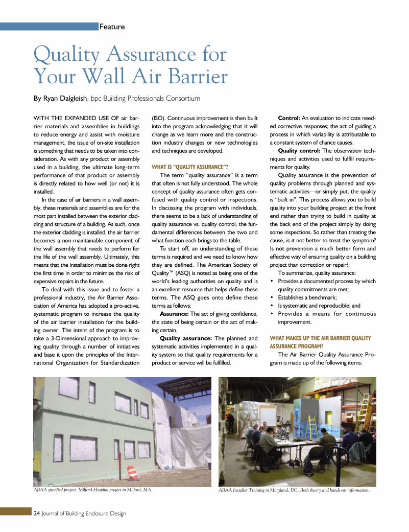
ABAA Installer Training in Maryland, DC. Both theory and hands-on information.ABAA specified project. Milford Hospital project in Milford, MA.

Winter 2008 25
research;•Standards and specifications;•Product validation;•Contractor accreditation;•Training;•3• rd Party Certification for installers and auditors;Trade testing and inspection;•Documentation;•3• rd party auditing; andConflict resolution.•A quick summary of each of the items
provides further insight:Research: In-field and laboratory testing
of materials, components, assemblies and systems by credible research bodies such as oak ridge National laboratories (orNl) and industry help provide reliable and cred-ible answers to questions the industry may have with regards to material performance, design or installation issues and real life per-formance. As research is completed, it can be disseminated to the field.
Standards and specifications: The Air Barrier Association of America (ABAA) is very active in developing guide specifica-tions for architects on how to properly specify various types of air barrier materials, and working with groups such as ASTM in developing a number of standards for test-ing materials, assemblies, installation, inspec-tions, durability and so forth. Currently two air barrier standards exist for testing the air permeance of a material (ASTM E2170 and the air permeance of an assembly (ASTM E2357). A number of other work items are in progress at ASTM. These provide the “benchmark” to the quality assurance program.
Product validation: ABAA has devel-oped performance criteria for various air
barrier materials through their technical committee. A manufacturer can apply to have its material evaluated against a set of performance criteria and have the prod-uct validated as meeting the predefined criteria. This provides a tool for designers to rely on when choosing a material, as no evaluation criteria currently exists in the uS market, such as the ICC evaluation services.
Contractor accreditation: ABAA Accredited Contractors must meet mini-mum requirements for insurance, bond-ing, employ certified installers, possess the necessary equipment to install and test their work, be trained in the Quality Assurance Program and sign a licensing agreement dictating professional conduct and the right to terminate their accreditation should they not meet the requirements of the program.
Education: Education is a very impor-tant component to ensuring quality. ABAA has taken a wide range approach to provid-ing education to all involved in the construc-tion process. First and foremost, education and training is provided to the installer of the air barrier of how to properly install the material, as he/she can have the single larg-est impact on the quality of the installation. ABAA also provides training programs for designers, general contractors, inspectors and others involved in the construction pro-cess to provide industry best practice and consistent information.
3rd Party Certification for installers and auditors: Certification is provided for the individual installers and auditors. Cer-tification criteria is defined and individuals can be eligible to receive certification after proving they have the knowledge. The cer-tification program provides the benchmark
for installation qualifications and knowl-edge and holds the individuals to meeting standards of professional conduct on an on-going basis in order to maintain their certification.
Trade testing and inspection: Cer-tified installers, on a daily basis, will per-form various forms of inspection and testing on the application of air barrier materials. This self testing program provides a mental checklist for the installer to conduct daily and provides a form of quality control.
Project installation documenta-tion: The certified installer is required to document the entire installation process on “daily work sheets”. These forms also allow the installer to document corrective action taken as part of their quality control program.
3rd party audits: on every project that is specified with the ABAA QAP program, an ABAA audit is conducted by a 3rd party. The number of audits performed on a spe-cific project is determined on the contract value of the project.
Conflict resolution: If there is a con-cern on a project by the design professional or owner, a dispute resolution system is in place to deal with any problems to make sure things are done right.
All of these initiatives and programs work together on an on-going basis and success is only achieved when this holis-tic approach is implemented as a system. Although each of the initiatives has merit in itself, the integration of all of them is what distinguishes this quality assurance program from other developed in the industry. Each item is intertwined with the next and each item feeds into each other. For instance, as research is conducted and new techniques
ABAA Certified Installers Daily Quality Control. Thickness testing of a liquid applied air barrier.
ABAA on-site audit in progress. Children’s Hospital, Wauwatosa, WI.

26 Journal of Building Enclosure Design
are established, this may impact what train-ing is needed, how to inspect completed work, and so forth.
how Can i gET air BarriEr qualiTy assuranCE on my ProjECT?
As a voluntary program, the ABAA QAP only comes into effect when specified in the project contract documents for the air bar-rier sub-trade. There are no building code requirements, nor industry standards that will automatically provide the owner or designer with a form of quality assurance.
whaT is ThE CosT?So, how much will incorporating the
air barrier QAP program add to the bot-tom line? Not much, based on the value of the program! As the entire program is a voluntary program, the additional costs for incorporating the program in a project is about 2.75 percent of the air barrier contract value. For instance, if the cost to supply and install the air barrier is $50,000, it would add around $1,500, as an estimate. This cost, for this case, would cover the cost of one site audit by an ABAA auditor and the management and administration fees of the program.
ConClusionThe ABAA Quality Assurance Program
has been designed to raise the professional-ism of the industry and benefit all parties involved. It takes a holistic approach to long-term quality and raising the standards within the industry. This program will help raise the bar to ensuring the long-term durability of our buildings, ensuring the energy efficiency benefits of an air bar-rier are achieved and to foster a mindset of continuous improvement. ■
Ryan Dalgleish is the Vice-President of the bpc Building Professional Consortium. BPC is a full service quality consulting and manage-ment firm that works with associations and industry across North America involved in energy efficiency and green buildings in both the residential and commercial industries. Dalgleish has been involved in the building envelope, building science and building perfor-mance areas of construction in for 10 years. He currently serves as the president of his lo-cal building envelope council (MBEC) and as president of the national building envelope council (NBEC).
Winter 2008 27
IF you’rE lookING For AN article which lays out a simple method to check some drawings and then end up with high-quality documents, well, you might as well stop here. If checklists, audits, peer reviews, office standards or anything similar could ensure even a minimum level of quality, let alone excellence, then these tricks already used widely by the industry, would be suf-ficient. The fact is, managing the design process to deliver high quality services, documents and in the end, the actual building is more of an art than a science. Central to delivering high quality service is the people involved and their skills, motivation, training and empowerment. Any design firm striving for quality, innovation and design excellence must focus on its staff.
dEfining qualiTyWhat is quality? one of the more significant problems with any
quality program is that defining quality is extremely difficult. Deal-ing with quality professional services versus a more tangible prod-uct creates many difficulties in assessing quality. When speaking about architecture, with many aspects inherently unquantifiable, then defining quality is nearly impossible. For this article “qual-ity” shall be defined as the level of design, innovation, service and project execution established by an individual design firm to serve its own needs and the needs of its clients.
moTivaTion in a dEsign firmAbsolutely essential for any firm to deliver quality is for the
individual members of that firm to be highly motivated to do so. of course they must have the requisite intelligence, knowledge and time but even with these things, if not motivated, mediocrity is likely. For the sake of this article, I will be talking about moti-vating architects but there are parallels for engineers, construc-tion managers and other service professionals in the construction industry.
Architects are motivated by the desire to see a great idea turned into an actual building. Although we sometimes focus on the drawings, any architect who has practiced long will inevitably talk about the indefinable but unmistakable feeling of fulfillment one gets visiting a job site for which you were part of the design team. So, while architects need good pay, job security and benefits, what really makes them tick is to be able to work on “cool” projects and be recognized for their contribution. By tapping into that desire an architectural firm can count on team members who are deeply, passionately committed
to the quality of a project. If you can feed this committed staff with knowledge, empowerment, recognition and guidance, they will make the project better than anyone’s expectations.
The key to managing quality in an architectural office is to walk the fine line between giving staff the knowledge to do the right thing within their own design solution versus simply telling them the solution. An architect who takes ownership of a design solu-tion will always do higher quality work.
ThrEE hElPful ToolsSeveral well recognized quality management systems can help
organize and manage a quality program. however, these pro-grams lack an emphasis on the individual team members. Instead, they either focus on verifying that a prescribed process is care-fully followed, without extensive checking of the content, or they attempt to thoroughly check a set of documents at a nearly com-plete state to find errors and omissions.
Perhaps the most well known quality program is the ISo 9000 system*. The International organization for Standardization pub-lishes documents which can guide the set up and administration of a quality program. The system is not dedicated to design or even service firms and in fact may be a better fit for manufacturing. The strength of the ISo 9000 program is that it forces the organization to put into writing the specific steps they themselves believe nec-essary to deliver quality. Behind this is the idea that if each step necessary for quality is followed, then quality itself will follow. The ISo program can ultimately result in ISo 9001 certification which requires outside auditing of the process. ISo Certification is more common in the u.S. for manufacturing firms but certifica-tion of design firms is not unusual in Europe. For design firms, it
is possible to carefully follow the prescribed steps, but if the individuals on the team are not really up to the task, quality will suffer.
Another quality system is “commissioning” such as put forth by AShrAE in Guide-
line 0-2005, The Commissioning Process**. The core tenets of commissioning is defining the owner’s project requirements (oPr),developing and documenting a design solution answering those requirements in a Basis of Design (BoD), and then checking off all future documentation and construction activities against the oPr and BoD.
The emphasis of commissioning on first understanding the owner’s needs and then checking back is an excellent process to
By David W. Altenhofen, AIA, RMJM Hillier
Feature
Managing QualityIt’s about the people, not the paper!
Central to delivering high quality service is the people
involved and their skills, motivation, training and
empowerment. Any design firm striving for quality,
innovation and design excellence must focus on its staff.

28 Journal of Building Enclosure Design
meet technical criteria (how many rooms, how big, what tem-perature, etc.) but provides little for aesthetic issues. Also, the commissioning process as written places a large emphasis on an outside commissioning agent who is responsible to somehow check the work of the design and construction team. I find this outside focus completely untenable and recommend that anyone investigating this particular commissioning system to instead inter-nalize the focus towards the project team.
rediCheck1 is both a methodology for checking of nearly completed construction documents and a professional service to conduct such checks. The rediCheck system does add rigor to a final independent checking which I highly recommend but I caution that it does not by itself ensure quality. For example, if a design assumption is flawed but otherwise properly documented, rediCheck may not catch the flaw. use rediCheck or a similar final review by someone not on the project team to check the completeness and coordination of a set of construction docu-ments but do not trust this one step to deliver quality.
CorPoraTE knowlEdgEEvery firm of more than a few people begins to develop a
corporate knowledge base, the collective knowledge of the indi-viduals that is larger than the knowledge of any individual within the firm. A central tenet of any quality program must be how to retain corporate knowledge and apply it to each project. office guide details, customized checklists, office master guide specifica-tions, etc. can and should be repositories for corporate data, the

Winter 2008 29
bits of information that make up corporate knowledge.
however, don’t confuse data with knowledge. Quality management must har-ness the knowledge of those individuals within the firm who have the most to offer a particular project and feed that knowl-edge into the project team. An excellent method is to conduct peer reviews at the beginning of project phases that include the project team and peers from outside the team. look for peers with senior level experience on similar projects but also include some “outsiders” who may bring an innovative approach unconstrained by past solutions.
There are no easy answers to providing quality. It takes a continuous and consistent message from the leadership of the firm that quality is important to them and that they recognize their staff as the only path to quality. Investing in the staff will garner their commitment, trust, and hard-work, and will result in high-quality work done in a productive manner by happy people. In the end, can we ask for much more? ■
noTEs* ISo 9000, www.iso.org.** ASHRAE Guideline 0-2005, The Commis-sioning Process, www.ashrae.org. See also, www.wbdg.org/project/buildingcomm.php.*** rediCheck, 109 Greensway, Suite 100, Peachtree City, GA 30269, www.redicheck-review.com.
rEfErEnCE1 The RediCheck system was developed in 1981 by William T. Nigro, AIA.
David W. Altenhofen AIA is the Technical De-sign Principal for RMJM Hillier, a 300 person architecture and design firm in New York, Princeton and Philadelphia with affiliated of-fices world-wide. He is responsible for man-aging the Technical Excellence Plan for the firm.
rECommEndaTions for PrEParing a qualiTy managEmEnT PlanEvery firm must custom design its own quality program around its own expecta-
tions, the peculiarities of its own practice, and its own professional goals. Below is a basic outline of preparing a quality management plan:
Firm leadership should discuss quality frequently to develop common expectations. •Appoint a principal to lead quality management but always emphasize that every principal must constantly reinforce quality. Establish a culture of excellence that is reinforced by daily actions.hire good staff, train them well and mentor them continually through their own •personal growth and through the development of the project.Ensure that firm leadership and project level leaders understand the importance of •training and empowerment. They likewise should be trained in the mentoring and training of the staff.Analyze the firm’s processes and history. Write out the steps you know are essen-•tial for quality.Manage for success. Start each project with a reasonable work plan that includes •more than just a fee burn-rate. Set milestones for key coordination and information transfer points. Check project progress against the plan make small periodic adjust-ments to keep up with the schedule rather than allowing the team to fall behind and then try to recover in the last weeks of CDs.Provide your staff with tools to do excellent work; CADD standards, checklists by •phase, guide details, specification guidelines, etc. Good tools provide for productiv-ity which allows time for good work. Start from commercial sources but customize the tools to suit your particular practice. Constantly update these tools with lessons learned from projects.Conduct timely reviews during the beginning of each phase to apply the assembled •knowledge of senior staff to each individual project. Such peer reviews can be the single most important tool to ensure that designs are solid, that owner’s project requirements are met, that the best knowledge of the firm is incorporated into the project and to lay a solid foundation for subsequent work without later backtrack-ing or duplication.require that a written document describing the owner’s project requirements and •the basis of design answering those requirements be developed for the end of sche-matic design and updated through the life of the project.require that your consultants perform similar quality assurance measures and ask •them to provide documentation that such measures have, in fact, been completed.Conduct quality control checks of each deliverable before it leaves the office to •ensure that the firm’s quality process has been followed and that deliverables meet quality expectations. The reviews should be performed by senior staff independent of the day-to-day project team. Allow sufficient time to make corrections before delivery, one or two days for small packages; up to two weeks for larger packages. Note that if the other aspects of the quality management plans have been followed then this final check should be minimal.require that your consultants perform similar quality assurance measures; ask them •to provide documentation that such measures have in fact been completed.Implement methods for continuing the quality process into the construction phases •by requiring senior review of important submittals, field testing of mock-ups, checklists, etc. and of course the emphasis on the staff doing CA.For liability reasons, it is recommended that records of performing the tasks •required of a quality management plan be maintained. however, it may not be desirable to keep records of the actual content of meetings and reviews. Discuss record keeping with your counsel.Continually monitor the quality management plan and adjust it based on feedback •from projects and changing conditions of the practice.
There are no easy answers to providing
quality. It takes a continuous and consistent
message from the leadership of the firm that
quality is important to them and that they
recognize their staff as the only path to quality.

30 Journal of Building Enclosure Design
ThE CoNSTruCTIoN MANAGEr’S INTErVIEW for Chil-dren’s Corporate Center at Children’s hospital of Wisconsin in Milwaukee focused on the need to create an energy efficient building that was pleasing to the eye, enjoyable to work in and could operate in Wisconsin’s wide ranging climate. The Boldt Company, along with architects Shepley Bulfinch, richardson & Abbott, Boston, and Zimmerman Architectural Studios, Wauwa-tosa, WI, took on this challenge.
Boldt’s Project Management Team implemented its Enclo-sure Quality Management (EQM) program. This program is designed to commission any building envelope through the use of Built In Quality (BIQ). The process consists of a plan review, mock up testing, on-site training, third party inspections and random site testing of installed products. The program was designed and implemented prior to the release of NIBS Guide-line 3-2006 Exterior Enclosure Technical requirements for the Commissioning Process, yet incorporates many of the same principles.
The first step of the EQM program occurred prior to the bidding process for the building enclosure components. Boldt reviewed all of the enclosure details and specifications to con-firm the proper use of barrier materials and their interfaces with adjacent materials. The review initiated discussions with
the designers, Shepley Bulfinch richardson & Abbott, and where warranted changes were made to the details. The review also aided in creating various lists of concerns and potential issues for the different enclosure disciplines. These lists were used in the interview process, preconstruction meetings and Boldt’s Quality Assurance Program.
The construction, full testing, documentation and implementa-tion of lessons learned from an enclosure mock up constituted the next phase of the EQM program. The mock up was built and test-ed at Architectural Testing Incorporated (ATI), located in york, Pa. The subcontractors for the project were required to send their lead men (who were then required to be a part of the instal-lation team on the project) out to the testing facility to install their materials. The “hands on” experience and knowledge attained by installing the materials prior to it actually being installed on the building proved to be invaluable.
For the mock up’s first series of air infiltration, moisture, ther-mal and structural tests, the contractors, architects, third party consultants and Boldt representatives were on hand to witness the issues that were discovered. The team reviewed each issue and agreed upon a potential solution and path forward. This pro-cess continued until the mock up passed all of the required tests. The mock up proved to be an integral part of the construction
By Brian Stroik, The Boldt Company
Feature
Case Study: Commissioning of the Building Envelope of Children’s Corporate Center Milwaukee, Wisconsin
ASTM 1186 Smoke Test performed on the actual building enclosure.
Children’s Corporate Center is an eight-level, 280,000 square foot office building located one block west of Children’s Hospital of Wisconsin. The building opened in December, 2005. Photo courtesy of the Children’s Hospital and Health System.

Winter 2008 31
process and led to a number of manufacturing, schedule sequenc-ing, and installation sequence changes prior to the building’s enclo-sure being constructed on site.
The Boldt Company integrated the information and lessons learned from the mock up and created a training program that every tradesman that worked on the building envelope was required to attend. The training program emphasized the impor-tance of installing the work properly the first time and reviewed the failures from the mock up testing along with discussing other high risk areas that were part of the envelope design. The on site training program instilled a sense of teamwork and stressed the importance of each worker and his diligence to the project details. Most importantly it let the tradesmen know how important com-munication is and that it was okay to ask questions if something in the field did not appear correct.
As the building enclosure construction began, the EQM pro-gram moved into its next phase: Boldt’s Quality Assurance Pro-gram and third party consultant site visits. Boldt’s QA Program emphasizes proactive measures by requiring foremen and/or superintendents to regularly review and document that their mate-rial has been installed correctly by their field personnel. The third party consultants included a curtain wall (unitized system) consul-tant who visited both the site and glazers manufacturing plant, an air and vapor barrier consultant who performed visual inspections, pull tests, and smoke tests (ASTM E 1186-03), and audits by the Air Barrier Association of America. All of the consultants made
numerous trips to the job site at various times, thus ensuring con-tractors did not become complacent in their work.
As the work on the enclosure progressed, Boldt hired ATI to field test the interfaces of various components and individual sys-tems. The first series of these tests were conducted early on so as to eliminate the possibility of a repetitive problem being over-looked and installed throughout the facade. The most common tests performed on site were: ASTM E 1105 (Field Determination of Water Penetration of Installed Exterior Windows, Curtain Walls and Doors by uniform or Cyclic Static Air Pressure Difference) and AAMA 502-02 (Voluntary Specification for Field Testing of Windows and Sliding Glass Doors, Test Method A).
The Enclosure Quality Management process Boldt utilized to commission the exterior envelope of the Children’s Corporate Center proved to be successful as the building functions and per-forms as it was designed. The EQM process along with the les-sons learned from this project are currently being employed on a 12-story, 425,000 square foot hospital addition underway at Chil-dren’s hospital. In conclusion, contractors whom facilitate com-missioning of the building envelope need to recognize that this is a system which contains numerous processes starting at the design phase and continuing through to the completion of the project. ■
Brian Stroik is the Quality Process Manager for Oscar J. Boldt’s Central Operations Group and specializes in field quality assurance process de-velopment and building enclosures.

32 Journal of Building Enclosure Design
In the Summer 2007 edition of JBED Terry Brennan and Michael Clarkin talked about what a fan pressurization test is, why it’s impor-tant and how to go about completing one. In Part II of their article, they’ll explain what the results of the test actually mean.
mEasuring PrEssurE diffErEnCEs
Electronic micromanometers designed for use in pressure test-ing buildings are available from the blower door manufacturers. A micromanometer has at least two air ports. A pressure sensitive transducer measures the air pressure difference between the two ports. Flexible tubing can be attached to each port so pres-sure differences between two locations that are distant from each other can be measured. Figure 1 shows a two channel micro-manometer. The green tubing runs to an outdoor measurement location. 2.1 Pascals air pressure difference is measured between the outdoor end of the tube and the open port at the bottom left. The building in this photo has none of the test fans operating—the pressure difference is due to a slight breeze. The blue tube runs to the flow nozzle on a blower door. The display switches between the two channels using the round knob below the display.
Wind and stack effect have important effects on pressure dif-ferences. Building air pressure is lower inside than outside on the windward side of the building; higher inside than outside on the leeward side. on sides parallel to wind usually the building is slight-ly lower air pressure than outside. When outdoor air is colder than indoor air the air pressure at the top of the building is higher than outdoor air and the air pressure at the bottom of the building is
lower than outdoor air. The ASTM, ATTMA and CGSB standards provide guidance for dealing with these problems.
The wind and stack problems found while conducting tests on small single zone buildings are compounded in larger, more com-plex buildings. In addition, uneven depressurization or pressuriza-tion between floors or zones during the test can produce errors in larger, multi-zone buildings. For example, in a two story office building with the first and second floor connected mostly by open doors at the top and bottom of a stairwell, and entry doors on the first floor the only place to install blower doors, the pressure difference between the first floor and the outdoors may be sig-nificantly greater than the pressure difference between the second floor and outdoors. Sometimes this problem can be mended by placing a fan door in a window opening or a roof hatch. Sometimes exhaust fans or outdoor air fan on the second floor can be used to produce more uniform pressure differences across the enclosure.
In larger buildings there is a great advantage to simultaneously measuring the pressure difference between indoors and outdoors at several locations or between floors and zones. This gives imme-diate feedback on the effect wind, stack and interzonal airflow resistance is having on the pressure differences across all walls. recording the data allows later analysis when data points with the smallest differences between orientations can be used. An eight channel micromanometer from the Energy Conservatory is shown in Figure 2. For this test four of the channels measure the pres-sure difference across four wall orientations, one channel mea-sures the pressure difference between first and second floor and
By Terry Brennan and Michael Clarkin, Camroden Associates Inc.
Feature
Characterizing Air Leakage in Large Buildings: Part II
Figure 1 – A two-channel micromanometer.
Figure 2 – An eight channel pressure difference datalogger.

Winter 2008 33
the remaining three channels measure the pressure drop across the flow orifices for three blower doors. NoTE: If using tubing longer than 100 feet, the tiniest airleaks cause erroneous pressure difference measurements. Accuracy must be verified across each wall if tubing longer than 100 feet is used.
Figure 3 shows a time series of pressure difference data across four walls during a test. At the beginning of the trace the building is being pressurized using a trailer mounted G54 and one blower door—a total of around 66,000 cfm. A second blower door is
turned on at 13 minutes adding another 6,000 cfm and increasing the indoor/outdoor pressure difference by 6 to 8 pascals. A third blower door is turned on at around 17 minutes, increasing the indoor outdoor pressure difference again. Notice the time lag between when the additional air was supplied and when the pressure difference stabi-lizes. This is due to the data collection time interval and the rather large 32,000,000 cubic foot volume of the warehouse being tested.
During the test the wind was from the north-east. The pressure difference across the north and east walls are usually within a pascal of each other. The pressure difference across the south and west walls are usually within a pascal of each but are generally 1 to 2 pascals greater than the north and east wall. This is consistent with the wind direction. With the graph plotting on the computer screen in real time, data at each new flow can be collected
long enough to assure small wind effects are noticed, and fan flows can be adjusted to maintain uniform pressure differences for mul-tiple zones.
If you are testing the building at multiple airflow-pressure points, it is a good idea to plot the data and do the regression anal-ysis as the data is collected. outliers become obvious and can be retested. At the very least, plot the data while the test equipment is still setup. It’s an expensive mistake to discover consistent data when everything is taken down and you’re back at the office.
ASHRAE 2005, Handbook of Fundamentals, American Society of Heating Refrigeration and Air-conditioning Engineers, 2005.
ATTMA 2006, ATTMA Technical Standard 1. Measuring Air Permeability of Building Envelopes, Air Testing and Measurement Association 2006.
Brennan 2002, Brennan, T., Cummings, J. “The Moisture Impact of Unplanned Airflows in Buildings”, ASHRAE Journal November, 2002.
Brennan 1997, Brennan, T., Clarkin, M., Lstiburek, J., Turner, W. “Unin-tended Consequences of Planned and Unplanned Airflows in Commercial Buildings” ASHRAE Healthy Buildings/IAQ 97, held at NIH, Bethesda, MD, September 1997.
CGSB 1996, CGSB-149.15-96 Determination of the Overall Envelope Airtightness of Buildings by the Fan Pressurization Method Using the Build-ing’s Air Handling Systems, Canadian General Standards Board, 1996.
Cummings 1996, Cummings, J.B., C.R. Withers, N. Moyer, P. Fairey, B. McKendry, “Uncontrolled Air Flow in Non-Residential Buildings”, Prepared for Florida Energy Office, Department of Community Affairs, FSEC-CR-878-96, March 29, 1996.
Cummings 1996, Cummings, J. B., C.R. Withers, N. Moyer, P. Fairey, and B. McKendry. “Field Measurement of Uncontrolled Air Flow and Depres-surization in Restaurants”. ASHRAE Transactions, 1996, Vol.102, Part 1, p.859.
Emmerich 2007, Emmerich, S. “Impact of Airtightness on Energy Use”. Journal of Building Enclosure Design” Winter 2007.
Emmerich 2005, Emmerich, S., Persily, A., McDowell, T., “Impact of
Commercial Building Infiltration on Heating and Cooling Loads in U.S. Office Buildings” Conference proceedings “Ventilation in Relation to the Energy Performance of buildings”, AIVC, 2005.
Henderson 2006, Henderson, H. et al “Mitigating the Impacts of Uncon-trolled Air Flow on Indoor Environmental Quality and Energy Demands in Non-residential Buildings”, New York State Energy Research and Develop-ment Association, 2006.
Lee 1998, Lee,B. “Protocol for Field Testing of Tall Buildings to Determine Envelope Leakage Rate”, Masters Thesis, Architectural Engineering Depart-ment, Pennsylvania State University, 1998.
Lstiburek 2007, Lstiburek, J. “The Hollow Building”. ASHRAE Journal June, 2007.
PECI 2005, Portland Energy Conservation Inc., TG12 Envelope Leakage Test, PECI Functional Testing Guidance, 2005.
Persily 1986, Persily, A., “Airtightness of Commercial and Institutional Build-ings: Blowing Holes in the Myth of Tight Buildings”, Thermal Envelopes VII Conference, 1998 Clearwater, FL.
Persily 1999, Persily, Andrew K. “Myths About Building Envelopes.” ASHRAE Journal, March 1999.
Potter 2007, Potter, N. “Air Tightness: The British Experience” Journal of Building Enclosure Design” Winter 2007.
SMACNA 2002, HVAC Systems Testing, Adjusting and Balancing, Sheet Metal and Air Conditioning Contractors National Association, Inc., 2002.
Figure 3 – Continuous pressure difference data reveals the impact of changing pressurization air flows and the effect wind has on the pressure differences.
ReFeReNCeS FRoM Both PARt I ANd PARt II oF the ARtICLe

34 Journal of Building Enclosure Design
whaT doEs iT mEan?Analysis of the data and interpretation depends on the purpose
of the test. If the purpose is to compare the enclosure tightness to a target—for example specified as performance criteria by owner, designer or regulation—then the analysis must report the result in the same measurement units as the target specification. The mea-surements must be made so the uncertainty in the result is small compared to the target tightness level. For example, if the target is the same as the British normal practice of 6 m3/hr@50pascals
per m² of enclosure (where enclosure area includes the top, bottom and exterior sides of the building), then the results must be converted to these units. The British ATTMA standard (multi-point test), ASTM E-779-03 (multi-point test) and ASTM E-1827-96 (single-point and two-point test) each provide criteria for bias and uncertainty, corrections for air density and accounting for environmental conditions.
The tightness of an enclosure can also be compared to similar buildings that have been previously tested. Figure 4 shows a histogram of the measured airtight-ness of 229 large building enclosures collected by the National Institute of Science and Technology from a number of data sources (Emmerich 2005). The results are reported in m3/hr@75 pascals per m2 surface area (where the surface area includes the roof, bottom floor and exterior walls of the enclosure). Enough data has been collected to see that the distribution is log-normal. To give some perspective on the data:
British Part l energy requirements require office buildings to •be air sealed to an airtightness of 10 m3/hr@50 pascals per m2 surface area; for comparison to the NIST data set this is converted to 13 m3/hr or 3.6 l/s @75 pascals per m2 surface area—assuming n=0.65 (Potter 2007). Just over 28 percent of the buildings in the dataset meet this target.British normal practice for office buildings is 5 m• 3/hr@50 pas-cals per m2 surface area (6.5 m3/hr or 1.8 l/s @75 pascals per m2 surface area—assuming n=0.65) (ATTMA, BSrIA). Just over 6 percent meet this target.British best practice for office buildings is 2 m• 3/hr@50 pascals per m2 surface area (2.6 m3/hr or 0.72 l/s @75 pascals per m2 surface area—assuming n=0.65) (ATTMA, BSrIA). Two of the buildings in the dataset are within 10 percent of this target, but none definitively meet it.
o For commercial buildings henri Fennell suggests a State of the Art target of 2.7 m3/hr@50 pascals per m2 surface area (3.5 m3/hr or 0.97 l/s @75 pascals per m2 surface area—assuming n=0.65) (Fennell 2005). Just over 2 per-cent of the buildings meet this target.
o AShrAE Addendum z to 90.1 2004 allows 2 l/s @ 75 Pa per m2 surface area.
o uS Army Corps of Engineers airtightness requirement is set at 1.25 l/s @ 75 Pa per m2 surface area.
The challenge to those designing high performance buildings is to meet the airtightness target values listed above, placing their buildings in the tightest few per cent of the building stock. To routinely achieve these target levels the construction documents must contain drawings and specifications detailing continuity of an air barrier system in all sections. It must be clear enough that con-tractors can understand what must be done. Pressure testing is an important tool in helping those who design and build to learn what is needed to air seal to meet airtightness target levels. ■
Terry Brennan and Michael Clarkin are building scientists who work at Camroden Associates Inc. They have been pressure testing buildings since 1981.
Figure 4 – Histogram of enclosure tightness measurements for large buildings.

Winter 2008 35
BosTonBy Jonathan Baron, AIA, Spagnolo Gisness & Associates, Inc.
The Boston-BEC continues to meet monthly (except for August and Decem-ber) for one and a half to two hours at the BSA headquarters in Boston’s Financial District. recent presentations have includ-ed a review of the jury process for the first BEC-Boston Award for the Most Innova-tive Building Enclosure, Cellulose Insulation by Betsy Petit of Building Science Corpo-ration, Fall Protection by Brent laPorte of Pro-Bel Enterprises, ltd., and Sound Transmission through the Building Envelope, by Jeff Fullerton of Acentech, Inc. We typi-cally have 20 to 30 attendees at our meet-ings, and there is always spirited discussion with the presenters.
The BEC sponsored a number of events at Build Boston, in November 2007, including a presentation of the first BEC-Boston Award for the Most Innovative Building Enclosure. Members of the jury reviewed the winning project, 60 oxford Street at harvard university, and mem-bers of the project team described the project and the sensitive treatment of the building enclosure.
upcoming meetings will focus on the effects of structural movement on build-ing enclosures and the interrelationship of AShrAE 90.1 and enclosures. More infor-mation about our current initiatives as well as future and past meetings can be found at our website www.bec-boston.org.
marylandBy H. Michael Hill, AIA, Torti Gallas and Partners, Inc; Fiona Aldous, Wiss, Janney, Elstner Associates, Inc.; and Paul E. Totten, PE, Simpson Gumpertz & Heger Inc.
Following successful and well attended programs featuring understanding Gar-den roofs and Selling Them to Clients; Curtain Wall Fabrication and Cladding of 1101 New york Avenue; Wind Informa-tion for Ballasted roofing Systems; What is a Window Wall?; Stone Cladding Design Considerations: An overview; and Double Skin Facades, the DC-BEC ended the year
2007 with a “town hall meeting” to intro-duce the new co-chairs and brainstorm the needs and expectations of our local BEC community.
David A. harris, FAIA, President of NIBS addressed the group with accolades to Tim Taylor and Bob Tarasovich for their devo-tion to sustaining the council with interest-ing and relevant monthly programs since our beginning in February 2005. harris applauded us for continuing the effort of providing a means by which the DC, NoVA and MD building envelope community with interest in the enclosure and related build-ing science can discuss and obtain informa-tion. A format of quarterly themes will be explored, with the first series of 2008 addressing “unnatural Forces” on the build-ing enclosure. Presentations will explore the relationships and issues associated with the building enclosure and fire, sound and blast. Although these events do naturally occur, their existence beyond the natural poses unique challenges to the designer to mitigate and control. The January 2008 topic of fire was presented by Dr. Jonathan Barnett and included discussion on fire and smoke controls for atria, as well as design considerations for phased occupancy.
Meetings for the first quarter will con-tinue to convene at Gensler’s office on the first Wednesday of each month at 4pm.
minnEsoTaBy Judd Peterson, AIA, BEC-Minnesota Co-chair and Jodelle Senger, AIA, LEED AP, BEC-Minnesota Co-chair
The BEC-Minnesota is preparing for the BEST 1 Symposium which will be held in Minneapolis, MI on June 10-12, 2008. Top-ics and speakers have been selected. We are now in the process of securing spon-sorships from national and regional com-panies that have a strong interest in the building enclosure. We hope that every-one will be able to attend and participate in this historic event. We also hope that the valuable information that is learned from this conference can lead to advance-ments in both energy efficiency and dura-bility of the building exterior. Please visit
the conference website to find out more about this exciting event, www.thebest-conference.org.
our local BEC continues to grow as we invite interesting experts to speak at our monthly meetings. recent speakers and topics have included John Edgar of Sto Corporation: recommended Application Systems for EIFS Stucco; Steve Pedracine of Minnesota lath and Plaster: residential Code Changes for Stucco Installations; and Al Gerhke of American hydrotech: Design and Installation of a Green roof. BEC-Min-nesota also hosted a seminar at our local AIA Convention in october 2007. Michael Petermann of Wiss, Janney, Elstner Asso-ciates, Inc. of New york and Ed Gerns of the WJEA Chicago office presented, “Are our Building Facades Safe?” which addressed building facade inspection ordi-nances. Since we received such interest in the topic, we continued the discussion at our November 2007 meeting, inviting the leaders of BoMA so we could hear their thoughts on the benefits and challenges of enforcing inspections. BEC-Minnesota has decided to survey key building owners to try to find a way to better protect the public without negatively impacting the building owner. We are looking forward to what 2008 has to offer.
PorTlandBy David C. Young, PE, RDH Building Sci-ences Inc.
After venue hopping each month for the past year, the Portland-BEC Chapter is happy to announce that our monthly meetings are now being held at the new Portland Center for Architecture, office of the AIA. We wish to thank all the compa-nies that provided space for our meetings over the past year and additionally, thank all presenters and attendees for being flex-ible with the changing venues.
The new AIA Center for Architecture building is a testament to green design. The existing single story building was reno-vated as an example of carbon neutral construction techniques. The building cal-culates to be 83 percent below the current
Industry update
BEC Corner

36 Journal of Building Enclosure Design
did you know?The National Institute of Building Sci-
ences (NIBS) was authorized by the u.S. Congress in the housing and Community Development Act of 1974, Public law 93-383. In establishing NIBS, Congress recognized the need for an organization that could serve as an interface between government and the private sector. The Institute's public interest mission is to improve the building regulatory environ-ment; facilitate the introduction of new and existing products and technology into the building process; and disseminate na-tionally recognized technical and regula-tory information.
As a non-profit, non-governmental organization, NIBS brings together rep-resentatives of government, the pro-fessions, industry, labor and consumer
interests to focus on the identification and resolution of problems and potential problems that hamper the construction of safe, affordable structures for hous-ing, commerce and industry throughout the united States. NIBS provides an au-thoritative source of advice for both the private and public sector of the economy with respect to the use of building science and technology. Congress recognized that the lack of such an authoritative voice was a burden on all those who plan, de-sign, procure, construct, use, operate, maintain and retire physical facilities, and that this burden frequently resulted from failure to take full advantage of new useful technology that could improve our living environment.
NIBS’ councils and standing com-mittees, which include the Consultative
Council, the Seismic Safety Council, the Building Enclosure Technology and En-vironment Council, the Facility Informa-tion Council, the buildingSMArT Alliance, the Multihazard Mitigation Council and the Facility Maintenance and operations Committee, focus on broad-based and specialized building process issues. Each specialty council is governed by a volun-tary board of direction comprised of na-tionally recognized leaders in appropriate disciplines.
NIBS is headquartered in Washing-ton, D.C. and is directed by a 21-mem-ber Board of Directors, 15 of whom are elected and six of whom are appointed by the President of the united States, sub-ject to the approval of the u.S. Senate.
For more information go to www.nibs.org.
AShrAE Co2 emissions. The facility will be used as an educational center for both the design community and the community at large for environmentally responsible design. The space suits our needs perfectly
and we look forward to the upcoming seminars we have planned this year.
The new year is appropriately starting out with green topics such as passive solar design and day-lighting. Seminar topics
later in the year will focus on roofing and seismic considerations for brick veneer cladding. We are also planning a flashing rodeo this summer after witnessing the success of the Charleston, SC event. ■
Winter 2008 37
AIR AND VAPOR BARRIER hohman and Barnard Inc. .........36, 37
ARCHITECTURAL GLASS oldcastle Glass ..........................22, 23
ARCHITECTURAL WINDOWS oldcastle Glass ..........................22, 23
ASSOCIATIONS ABAA ............................................... 31 Indoor Air Quality Association ............inside front cover
BUILDING ENCLOSURE Construction Consultants International .................................. 26
BUILDING ENVELOPE CONSULTANTS Conley Group .................................. 26
BUILDING SCIENCE & RESTORATION CONSULTANTS read Jones Christofferson ............... 28
ENGINEERED WALL AND WINDOW WALL oldcastle Glass ..........................22, 23
ENGINEERS Sutton-kennerly & Associations ...... 34
ENTRANCE SySTEMS SPARE PARTS oldcastle Glass ..........................22, 23
INSULATION MANUFACTURER knauf Insulation .....outside back cover
MANUFACTURER REFLECTIVE ROOF COATINGS, LEED COMPLIANT karnak Corporation .......................... 8
MASONRy Mortar Net uSA ltd. ...................... 20
MINERAL WOOL INSULATION roxul Inc. ........................................... 6
RAINSCREEN STUCO ASSEMBLy Stuco-Flex International .................... 3
ROOFING MANUFACTURER GAF Materials .................................... 4
STRUCTURAL ENGINEERING, DESIGN & CONSULTANTS Wiss, Janney, Elstner
Associates, Inc. .............................. 28
WATERPROOFING Sto Corp. ................. inside back cover
WEATHER BARRIER Cosella Dorken ............................... 15
Buyer’s Guide
PlEasE suPPorT our advErTisErs.
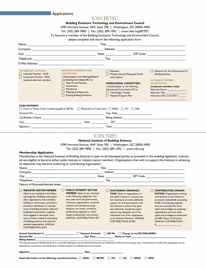
JOIN BETECBuilding Enclosure Technology and Environment Council
1090 Vermont Avenue, NW, Suite 700 | Washington, DC 20005-4905Tel: (202) 289-7800 | Fax: (202) 289-1092 | www.nibs.org/BETEC
To become a member of the Building Enclosure Technology and Environment Council, please complete and return the following application form:
Name: ______________________________________________ Title: ___________________________________________________
Company: ______________________________________________ Address: _____________________________________________
City: ______________________________________________ State: _________________ ZIP Code: _________________________
Telephone: ______________________________________________ Fax: ________________________________________________
E-Mail Address: __________________________________________
JOIN NIBSNational Institute of Building Sciences
1090 Vermont Avenue, NW, Suite 700 | Washington, DC 20005-4905Tel: (202) 289-7800 | Fax: (202) 289-1092 | www.nibs.org
Membership ApplicationMembership in the National Institute of Building Sciences is open to all interested parties as provided in the enabling legislation. Individu-als are eligible to become either public interest or industry sector members. organizations that wish to support the Institute in achieving its objectives may become sustaining or contributing organization.Name ______________________________________________ Title ___________________________________________________Company ______________________________________________ Addres _____________________________________________City ______________________________________________ State _________________ ZIP Code _________________________Telephone ______________________________________________ Fax ________________________________________________Nature of Business/interest areas: _________________________________________________________________________________
Annual Contribution $ __________________________ c Payment Enclosed c Bill Me c Charge to my MC/VISA/AMEX:Account No. __________________________________________ Exp. Date_______________ Name on Card _____________________________________________Billing Address _________________________________________________________________The National Institute of Building Sciences is a nonprofit organization with an Internal revenue Service Classification of 501(c)(3) tax exempt status. Contributions to all 501(c)(3) organizations are tax
deductible by corporations and individuals as charitable donations for federal income tax purposes.
Signature ____________________________________________ Date ___________________________
Send information on the following council/committee: c BSSC c BETEC c FIC c IAI c FMOC c MMC
DUES PAyMENT:c Check or Money order enclosed payable to BETEC c Please bill my Credit Card: c AMEx c MC c VISA
Account No. ___________________________________________________ Exp. Date _________________________
Cardholder’s Name _____________________________________________ Billing Address ________________________________________________
City __________________________________________ State _____________ ZIP ___________________________
Signature ______________________________________________________ Date _____________________________
MEMBErShIP CATEGory:c Individual Member - $100c Corporate Member - $250
(optional alternate member)
rESEArCh CoorDINATING CoMMITTEES:I will participate on the following research Coordinating Committees (rCC’s):c heat Air and Moisturec Fenestrationc Membranesc Materials and resources c Existing Building Enclosures
c Educationc Window Security rating and Certifi-
cation System
OPERATIONAL COMMITTEES:I will participate on the following operational Committees (oC’s):c Technology Transferc National Program Plan
c Network for the Advancement of Building Science
AlTErNATE MEMBEr INForMATIoN (corporate members only):Alternate Name: ________________Alternate Title: _________________Alternate’s rCC’s and oC’s: ______ ______________________________
c INDUSTRy SECTOR MEMBER: open to any individual in the follow-ing categories: Building construction; labor organizations; home builders; building or construction contractors; producers, distributors or manufac-turers of building products; trade and professional associations; organiza-tions engaged in real estate, insur-ance or finance; research and testing of building products; and code and standard organizations. ANNuAl CoNTrIBuTIoN: $150
c PUBLIC INTEREST SECTOR MEMBER: open to any individual in the following categories: Fed-eral, state and local government, consumer organizations, nonprofit research and educational orga-nizations, the media, architects, professional engineers or other design professionals, and retirees. ANNuAl CoNTrIBuTIoN: $75
c SUSTAINING ORGANIZA-TION: open to organizations in the public interest or industry sec-tors desiring to provide additional support for and participation with the Institute to achieve the goals and objectives. Sustaining organi-zations may designate up to five individuals from their organization to be Institute Members. ANNuAl CoNTrIBuTIoN: $1000
c CONTRIBUTING ORGANI-ZATION: organizations making contributions to the Institute in an amount substantially exceeding $1000. Contributing organiza-tions are accorded the same rights and privileges as sustaining organizations and such other rights and privileges as authorized by NIBS’ Board of Directors. ANNuAl CoNTrIBuTIoN: $______________________
Applications