january 2021 - rev. 02 snv/de - vorticeindustrial.com
TRANSCRIPT

100
SCRO
LL
R410A
EC
SNV/DE SWIMMING POOL DEHUMIDIFIERS
INTRODUCTIONIn indoor pools, the air temperature normally varies between 28 °C and 35 °C and, in general, the air temperature inside the rooms is always warmer than the outside air. In these rooms, the high degree of evaporation of the water, leads to a high level of humidity and the unpleasant feeling of an oppressive heat. If you do not control the humidity, not only is the time spent in an indoor pool perceived as unpleasant, but there is a risk that the humidity contained in the water vapour will condense on cooler surfaces, such as metal components, external walls or glass surfaces.This can lead to the formation of mould and cause corrosion. In addition, the ventilation of swimming pool rooms involves considerable energy consumption and the costs of a good
heat recovery system, in private or small applications and with moderate outside temperatures, do not allow returns on investment in a satisfactory time. For this reason, in private pools, hotel pools, wellness centers and therapeutic areas and in all those applications where the use of fresh air is not required by specific regulations, dehumidifiers with full recirculation can be used. These units are normally installed in a central service room with supply and return air ducts to the pool area. The air recirculation process guarantees an energy-efficient dehumidification system.All the thermal energy recovered from the high-performance heat pump circuit is completely returned to the environment, helping to reduce heating costs.

101
SNV/DE
-20 -15 -10 -5 0 5 10 15 20 25 30 35 40 45 50 55 60
DRY BULB TEMPERATURE - °C
5
10
15
20
25
30
SATU
RATI
ON
TEM
PERA
TURE
- °C
-15-10
-5
0 0
55
10
10
15
15
20
20
25
25 30 WET BULB TEMPERATURE - °C
30
15%
25%
2%
4%
6%
8%
10% RELATIVE HUMIDITY
20%
30%
40%
50%
60%
70%
80%
90%
.74
.76
.78
.80
.82
.84
.86
.88
.90 SP
EC
IFIC V
OLU
ME
m³/kg O
F DR
Y A
IR.92
.94 .96
.98
HU
MID
ITY
RA
TIO
- G
RA
MS
OF
MO
ISTU
RE
PE
R K
ILO
GR
AM
OF
DR
Y A
IR
1
2
3
4
5
6
7
8
9
10
11
12
13
14
15
16
17
18
19
20
21
22
23
24
25
26
27
28
29
30
31
32
33
34
STE
AM
PR
ES
SU
RE
- M
M O
F M
ER
CU
RY
-40-20
-10
0
10
20
25
30
DE
W P
OIN
T - °
C
OPERATING MODE
① Compressor ⑤ Expansion valve② Fan ⑥ Evaporator③ Condenser ⑦ Drain pan④ Filter
WET AIR
DRY AIR
gas
hot gas
liquid refrigerant
liquid / gas mixture
In practice, in a dehumidifier operating with a refrigeration cycle, the air passes through a finned evaporator, in which it is cooled by evaporation of the refrigerant gas; the dew temperature is reached and the water vapour condenses in the form of drops on the fins of the evaporator.The droplets are collected in the drain pan and evacuated through the drain pipe. Then, the freshly cooled and dehumidified air in the evaporator passes through the
condenser where it absorbs the condensation heat of the system. At this point, the air is reintroduced into the environment at a higher temperature and with a lower water vapour content. It is important to underline that the dehumidification treatment with refrigeration cycle is always solved with an increase in the air supply temperature. This aspect must be taken into consideration in installations where temperature control is necessary.
102
2
13
5
4
6
7
8
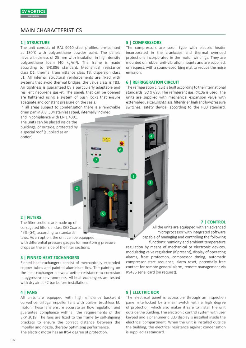
1 | STRUCTUREThe unit consists of RAL 9010 steel profiles, pre-painted at 180°C with polyurethane powder paint. The panels have a thickness of 25 mm with insulation in high density polyurethane foam (40 kg/m3). The frame is made according to EN1886 standard. Mechanical resistance class D1, thermal transmittance class T3, dispersion class L1. All internal structural reinforcements are fixed with systems that avoid thermal bridges; the value class is TB3. Air tightness is guaranteed by a particularly adaptable and resilient neoprene gasket. The panels that can be opened are tightened using a system of push locks that ensure adequate and constant pressure on the seals.In all areas subject to condensation there is a removabledrain pan in AISI 304 stainless steel, internally inclinedand in compliance with EN 1.4301. The units can be placed inside thebuildings, or outside, protected bya special roof (supplied as anoption).
2 | FILTERSThe filter sections are made up ofcorrugated filters in class ISO Coarse 45% (G4), according to standards laws. As an option, the unit can be equippedwith differential pressure gauges for monitoring pressure drops on the air side of the filter sections.
3 | FINNED HEAT EXCHANGERSFinned heat exchangers consist of mechanically expanded copper tubes and painted aluminium fins. The painting on the heat exchanger allows a better resistance to corrosion in aggressive environments. All heat exchangers are tested with dry air at 42 bar before installation.
4 | FANSAll units are equipped with high efficiency backward curved centrifugal impeller fans with built-in brushless EC motor. These fans ensure accurate air flow regulation and guarantee compliance with all the requirements of the ERP 2018. The fans are fixed to the frame by self-aligning brackets to ensure the correct distance between the impeller and nozzle, thereby optimizing performance.The electric motor has an IP54 degree of protection.
5 | COMPRESSORSThe compressors are scroll type with electric heater incorporated in the crankcase and thermal overload protections incorporated in the motor windings. They are mounted on rubber anti-vibration mounts and are supplied, on request, with a sound-absorbing mat to reduce the noise emission.
6 | REFRIGERATION CIRCUITThe refrigeration circuit is built according to the international standards ISO 97/23. The refrigerant gas R410a is used. The units are supplied with mechanical expansion valve with external equalizer, sight glass, filter drier, high and low pressure switches, safety device, according to the PED standard.
7 | CONTROLAll the units are equipped with an advanced
microprocessor with integrated softwarecapable of managing and controlling the following
functions: humidity and ambient temperatureregulation by means of mechanical or electronic devices, modulating valve regulation (if present), display of operating alarms, frost protection, compressor timing, automatic compressor start sequence, alarm reset, potentially free contact for remote general alarm, remote management via RS485 serial card (on request).
8 | ELECTRIC BOXThe electrical panel is accessible through an inspection panel interlocked by a main switch with a high degree of protection, which also makes it safe to install the unit outside the building. The electronic control system with user keypad and alphanumeric LED display is installed inside the electrical compartment. When the unit is installed outside the building, the electrical resistance against condensation is supplied as standard.
MAIN CHARACTERISTICS

103
SNV/DE
031 041 051 071 081 091 122 152 172 202 242
382.0 442.0 557.0 749.0 915.0 1066.0 1334.0 1604.0 1664.0 2255.0 2316.0
4.9 6.1 6.9 9.5 11.3 14.5 15.8 19.7 21.1 27.9 29.7
7.2 11.8 14.0 17.4 18.3 17.9 20.5 26.7 28.6 35.9 38.2
12.9 17.8 19.3 26.8 30.4 39.2 47.5 53.0 56.3 86.0 86.0
6.0 9.0 9.0 12.0 12.0 15.0 18.0 24.0 24.0 24.0 24.0
69.0 78.0 104.0 144.0 151.0 179.2 129.0 141.0 144.0 216.0 216.0
33.0 41.7 53.8 65.0 80.0 86.3 114.0 138.0 168.0 199.0 225.0
3500 4500 5500 7000 8500 9500 12000 15000 17000 20000 24000
250 250 250 250 250 250 250 250 250 250 250
1 / 1 1 / 1 1 / 1 1 / 1 1 / 1 1 / 1 2 / 2 2 / 2 2 / 2 2 / 2 2 / 2
R410A
2.5 2.7 4.2 5.2 6.8 6.8 9.6 10.4 12.0 15.0 15.0
2088
5.2 5.6 8.8 10.9 14.2 14.2 20.1 21.7 25.1 31.3 31.3
81.8 84.0 83.2 84.4 88.6 91.3 90.5 96.4 91.6 90.6 90.6
66.1 68.3 67.1 68.0 72.0 74.7 73.2 78.9 74.1 72.7 72.7
400 / 3 / 50
All units are fully assembled and wired at the factory, carefully vacuumed and dried after pressure tightness tests and loaded with R410A refrigerant, all subjected to functional testing before shipment.The units comply with European Directives, are individually marked with the CE mark and have a Declaration of Conformity.
TECHNICAL DATAMODEL
Moisture removed at 30°C - 80% (1) l/24h
Nominal input power at 30°C - 80% (2) kW
Maximum input power (2) kW
Maximum input current (2) A
Supplementary electric heater kW
Maximum starting current A
Hot water coil (3) kW
Air volume m3/h
Available static pressure Pa
Compressors / Refrigerant circuit nr.
Refrigerant gas
Refrigerant charge kg
Global warming potential (GWP)
Equivalent CO2 charge t
Sound power (4) dB(A)
Sound pressure (5) dB(A)
Power supply V/ph/Hz
(1) According to EN810 standards.(2) Unit without additional electric heater.(3) Room temperature 30°C; water temperature 80/70°C, compressor OFF.(4) Sound Power level according to EN 3744, ducted unit.(5) Sound pressure level measured at 1 mt from the unit in free field conditions according to EN 3744. Ducted unit.
UNIT TEST

104
40
35
30
25
20
15
10
30 40 50 60 70 80 90 10036 50 75 97
20
36
031 041 051 071 081 091 122 152 172 202 242
▪ ▪ ▪ ▪ ▪ ▪ ▪ ▪ ▪ ▪ ▪▪ ▪ ▪ ▪ ▪ ▪ ▪ ▪ ▪ ▪ ▪▪ ▪ ▪ ▪ ▪ ▪ ▪ ▪ ▪ ▪ ▪▪ ▪ ▪ ▪ ▪ ▪ ▪ ▪ ▪ ▪ ▪▫ ▫ ▫ ▫ ▫ ▫ ▫ ▫ ▫ ▫ ▫▫ ▫ ▫ ▫ ▫ ▫ ▫ ▫ ▫ ▫ ▫▫ ▫ ▫ ▫ ▫ ▫ ▫ ▫ ▫ ▫ ▫▫ ▫ ▫ ▫ ▫ ▫ ▫ ▫ ▫ ▫ ▫▫ ▫ ▫ ▫ ▫ ▫ ▫ ▫ ▫ ▫ ▫- - - ▫ ▫ ▫ ▫ ▫ ▫ ▫ ▫▫ ▫ ▫ ▫ ▫ ▫ ▫ ▫ ▫ ▫ ▫▫ ▫ ▫ ▫ ▫ ▫ ▫ ▫ ▫ ▫ ▫▫ ▫ ▫ ▫ ▫ ▫ ▫ ▫ ▫ ▫ ▫▫ ▫ ▫ ▫ ▫ ▫ ▫ ▫ ▫ ▫ ▫▫ ▫ ▫ ▫ ▫ ▫ ▫ ▫ ▫ ▫ ▫▫ ▫ ▫ ▫ ▫ ▫ ▫ ▫ ▫ ▫ ▫▫ ▫ ▫ ▫ ▫ ▫ ▫ ▫ ▫ ▫ ▫▫ ▫ ▫ ▫ ▫ ▫ ▫ ▫ ▫ ▫ ▫▫ ▫ ▫ ▫ ▫ ▫ ▫ ▫ ▫ ▫ ▫▫ ▫ ▫ ▫ ▫ ▫ ▫ ▫ ▫ ▫ ▫
ACCESSORIES
OPERATING LIMITS
Inte
rnal
tem
pera
ture
[°C]
Relative humidity [%]
MODELHigh efficiency E.C. fans ≤ 200 Pa
Supply flange
Mechanical expansion valve
Main switch
Remote mechanical hygrostat
Humidity & Temp. electronic probe sensor
Hot water coil
3 Way modulating valve kit installed
Electric heater kit 6 kW (400/3~/50)
Electric heater kit 12 kW (400/3~/50)
Serial interface card RS485
Remote control panel
Low noise version
Partial heat recovery
Stainless steel frame and panels
Roof for external installation
Frame for ducted installation
Flexible connections for ducts
High efficiency E.C. fans ≥ 200 Pa
Rigid bag filter ePM1 55% (F7) box
▪ Standard ▫ Optional - Not available

105
SNV/DE
L
W
H
L
W
H
031 041 051 071 081 091 122 152 172 202 2421250 1250 1610 1610 1810 1810 2130 2130 2430 2780 2780750 750 750 850 850 850 960 960 960 960 960
1340 1340 1430 1575 1625 1625 1900 2080 1875 2060 2060319 338 404 443 512 532 780 832 857 1025 1058
DIMENSIONAL DRAWING
DIMENSIONS AND WEIGHTS
MODEL L (mm)
W (mm)
H (mm)
Weight (kg)
Dimensions and weights referred to the standard configuration