january 17, 2018 ms. kimberly d. bose, secretary … postings/2018_01_17...1 northern natural gas...
TRANSCRIPT
1
Northern Natural Gas P.O. Box 3330 Omaha, NE 68103-0330 402 398-7200
January 17, 2018 Via eFiling Ms. Kimberly D. Bose, Secretary Federal Energy Regulatory Commission 888 First Street, N.E. Washington, D.C. 20426 RE: Northern Natural Gas Company Docket No. CP16-472-000 Northern Lights 2017 Expansion Project Faribault Compressor Station – Final Noise Survey Dear Ms. Bose:
Pursuant to Condition No. 14 of the Federal Energy Regulatory Commission’s (Commission) order issued January 30, 2017, in the above-referenced docket, Northern Natural Gas Company hereby submits for filing with the Commission its final noise survey for the Faribault compressor station.
Any questions regarding the filing should be directed to the undersigned at (402)
398-7103. Respectfully submitted, /signed/ Mike Loeffler Mike Loeffler Sr. Director, Certificates and External Affairs
Northern Natural Gas Company Northern Lights 2017 Expansion Project: Docket No. CP16-472-000 Faribault Compressor Station Post-construction Sound Report
Prepared for: Northern Natural Gas Company Omaha, Nebraska
Prepared by: Stantec Consulting Services Inc.
January 17, 2018
NORTHERN NATURAL GAS COMPANY NORTHERN LIGHTS 2017 EXPANSION PROJECT: DOCKET NO. CP16-472-000 FARIBAULT COMPRESSOR STATION POST-CONSTRUCTION SOUND REPORT
January 17, 2018
1
Table of Contents
ABBREVIATIONS ........................................................................................................................ 2
1.0 INTRODUCTION ............................................................................................................. 3
2.0 SITE DESCRIPTION .......................................................................................................... 3
3.0 SOUND LEVEL REQUIREMENT......................................................................................... 4
4.0 MEASUREMENT METHODOLOGY .................................................................................. 5
5.0 MONITORING RESULTS AND OBSERVATIONS ............................................................... 6
6.0 CONCLUSIONS .............................................................................................................. 6
LIST OF TABLES
TABLE 2.1 NSA SUMMARY FOR FARIBAULT COMPRESSOR STATION
TABLE 3.1 MPCA STATE NOISE STANDARDS
TABLE 5.1 AMBIENT SOUND PRESSURE LEVEL MEASUREMENTS SUMMARY
TABLE 5.2 ON-PROPERTY SOUND PRESSURE LEVEL MEASUREMENTS SUMMARY
APPENDICES
APPENDIX A: POST CONSTRUCTION NOISE ANALYSIS
APPENDIX B: H&K PRE-CONSTRUCTION SOUND SURVEY
NORTHERN NATURAL GAS COMPANY NORTHERN LIGHTS 2017 EXPANSION PROJECT: DOCKET NO. CP16-472-000 FARIBAULT COMPRESSOR STATION POST-CONSTRUCTION SOUND REPORT
January 17, 2018
2
Abbreviations
CFR Code of Federal Regulations
dB Decibel
dB(A) or dBA Decibel (A-weighted)
FERC Federal Energy Regulatory Commission
Facility Faribault Compressor Station
HP Horsepower
Leq Equivalent continuous sound level
Ld Equivalent continuous daytime sound level
Ln Equivalent continuous nighttime sound level
Ldn Day-night average sound level
Lp Sound pressure
Northern Northern Natural Gas Company
NSA Noise sensitive area
Project Northern Lights 2017 Expansion project
SLM Sound Level Monitor
NORTHERN NATURAL GAS COMPANY NORTHERN LIGHTS 2017 EXPANSION PROJECT: DOCKET NO. CP16-472-000 FARIBAULT COMPRESSOR STATION POST-CONSTRUCTION SOUND REPORT
January 17, 2018
3
1.0 Introduction Northern has completed construction and began operation of approximately 4.8 miles of branch line loop extensions and an additional compressor unit at Northern’s existing Facility. The Project consisted of: 1) an approximately 2.8-mile-long, 12-inch-diameter pipeline extending west from the end of Northern’s existing St. Cloud branch line loop and running adjacent to the St. Cloud branch line in Isanti County, Minnesota (St. Cloud Loop); 2) an approximately 2.0-mile-long, 8-inch-diameter pipeline extending south from the end of Northern’s existing Princeton branch line loop and running adjacent to the Princeton branch line in Sherburne County, Minnesota (Princeton Loop); and 3) the addition of one new 15,900-HP gas-driven compressor unit (Unit 2) at Northern’s existing Faribault Compressor Station in Rice County, Minnesota, which ties into Northern’s existing B-line, C-line, and D-line.
On December 21, 2017, Stantec completed a post-construction ambient sound survey of the Facility. The purpose of the survey was to quantify the sound level attributable to the Facility at nearby NSAs during operation and compare the measured and estimated sound level contribution to applicable sound criteria. During the sound survey, unit 1 was operating at maximum HP, while unit 2 was operating between 12,700 and 15,000 HP1.
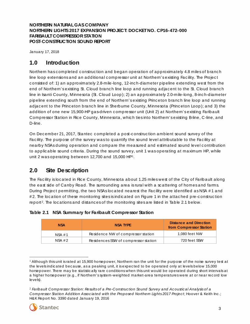
2.0 Site Description The Facility is located in Rice County, Minnesota about 1.25 miles west of the City of Faribault along the east side of Canby Road. The surrounding area is rural with a scattering of homes and farms. During Project permitting, the two NSAs located nearest the Facility were identified as NSA #1 and #2. The location of these monitoring sites is indicated on Figure 1 in the attached pre-construction report2. The locations and distances of the monitoring sites are listed in Table 2.1 below.
Table 2.1 NSA Summary for Faribault Compressor Station
NSA NSA TYPE Distance and Direction from Compressor Station
NSA #1 Residence NW of compressor station 1,080 feet NW
NSA #2 Residences SSW of compressor station 720 feet SSW
1 Although this unit is rated at 15,900 horsepower, Northern ran the unit for the purpose of the noise survey test at the levels indicated because, as a peaking unit, it is expected to be operated only at levels below 15,000 horsepower. There may be statistically rare conditions when this unit would be operated during short intervals at a higher horsepower (e.g., if Northern’s system-weighted market-area temperatures were at or near record low levels).
2 Faribault Compressor Station: Results of a Pre-Construction Sound Survey and Acoustical Analysis of a Compressor Station Addition Associated with the Proposed Northern Lights 2017 Project; Hoover & Keith Inc.; H&K Report No. 3390 dated January 19, 2016
NORTHERN NATURAL GAS COMPANY NORTHERN LIGHTS 2017 EXPANSION PROJECT: DOCKET NO. CP16-472-000 FARIBAULT COMPRESSOR STATION POST-CONSTRUCTION SOUND REPORT
January 17, 2018
4
3.0 Sound Level Requirement The FERC regulations at 18 CFR § 380.12(k)(2) state that any applicable state or local noise regulations be identified. 18 CFR § 380.12 (k)(4)(v) also specifies how a compressor station will meet the regulations. In the absence of any applicable state or local noise regulation, the FERC requires that pipeline noise impacts must not exceed a day-night noise level (L(dn)) of 55 dB(A) at any pre-existing NSA.
Internet searches were conducted to identify other applicable regulations for the Project. No state or local noise regulations were identified for Rice County or the local township.
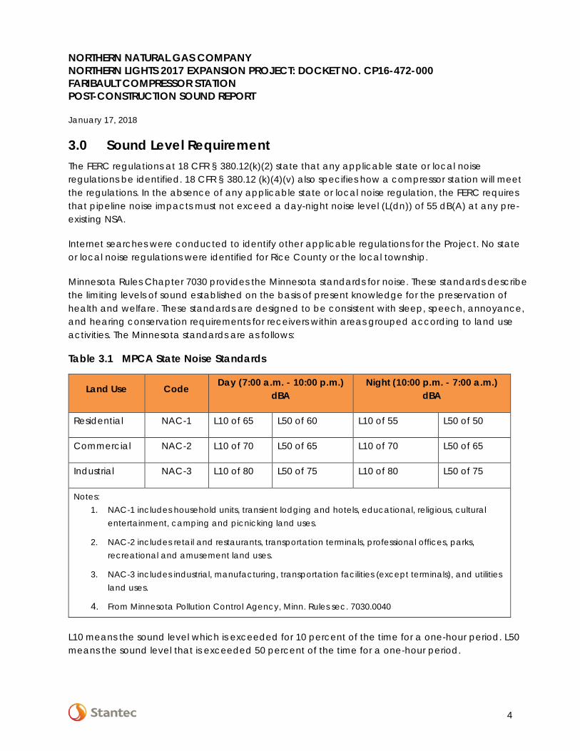
Minnesota Rules Chapter 7030 provides the Minnesota standards for noise. These standards describe the limiting levels of sound established on the basis of present knowledge for the preservation of health and welfare. These standards are designed to be consistent with sleep, speech, annoyance, and hearing conservation requirements for receivers within areas grouped according to land use activities. The Minnesota standards are as follows:
Table 3.1 MPCA State Noise Standards
Land Use Code Day (7:00 a.m. - 10:00 p.m.)
dBA Night (10:00 p.m. - 7:00 a.m.)
dBA
Residential NAC-1 L10 of 65 L50 of 60 L10 of 55 L50 of 50
Commercial NAC-2 L10 of 70 L50 of 65 L10 of 70 L50 of 65
Industrial NAC-3 L10 of 80 L50 of 75 L10 of 80 L50 of 75
Notes: 1. NAC-1 includes household units, transient lodging and hotels, educational, religious, cultural
entertainment, camping and picnicking land uses.
2. NAC-2 includes retail and restaurants, transportation terminals, professional offices, parks, recreational and amusement land uses.
3. NAC-3 includes industrial, manufacturing, transportation facilities (except terminals), and utilities land uses.
4. From Minnesota Pollution Control Agency, Minn. Rules sec. 7030.0040
L10 means the sound level which is exceeded for 10 percent of the time for a one-hour period. L50 means the sound level that is exceeded 50 percent of the time for a one-hour period.
NORTHERN NATURAL GAS COMPANY NORTHERN LIGHTS 2017 EXPANSION PROJECT: DOCKET NO. CP16-472-000 FARIBAULT COMPRESSOR STATION POST-CONSTRUCTION SOUND REPORT
January 17, 2018
5
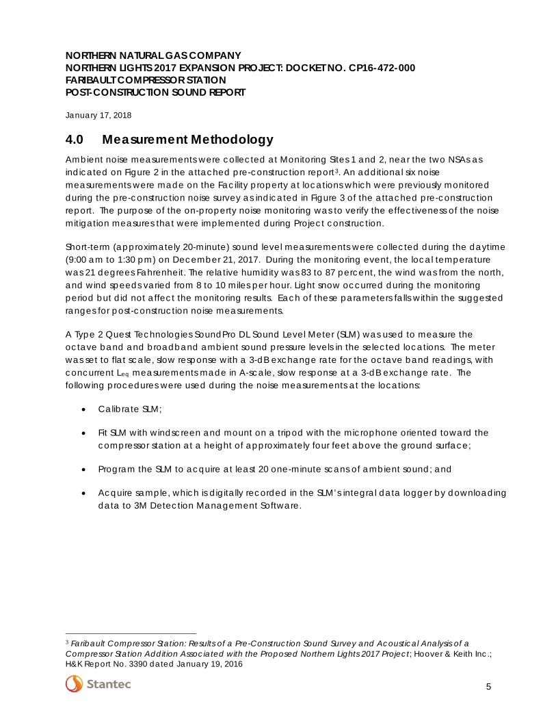
4.0 Measurement Methodology Ambient noise measurements were collected at Monitoring Sites 1 and 2, near the two NSAs as indicated on Figure 2 in the attached pre-construction report3. An additional six noise measurements were made on the Facility property at locations which were previously monitored during the pre-construction noise survey as indicated in Figure 3 of the attached pre-construction report. The purpose of the on-property noise monitoring was to verify the effectiveness of the noise mitigation measures that were implemented during Project construction.
Short-term (approximately 20-minute) sound level measurements were collected during the daytime (9:00 am to 1:30 pm) on December 21, 2017. During the monitoring event, the local temperature was 21 degrees Fahrenheit. The relative humidity was 83 to 87 percent, the wind was from the north, and wind speeds varied from 8 to 10 miles per hour. Light snow occurred during the monitoring period but did not affect the monitoring results. Each of these parameters falls within the suggested ranges for post-construction noise measurements.
A Type 2 Quest Technologies SoundPro DL Sound Level Meter (SLM) was used to measure the octave band and broadband ambient sound pressure levels in the selected locations. The meter was set to flat scale, slow response with a 3-dB exchange rate for the octave band readings, with concurrent Leq measurements made in A-scale, slow response at a 3-dB exchange rate. The following procedures were used during the noise measurements at the locations:
• Calibrate SLM;
• Fit SLM with windscreen and mount on a tripod with the microphone oriented toward the compressor station at a height of approximately four feet above the ground surface;
• Program the SLM to acquire at least 20 one-minute scans of ambient sound; and
• Acquire sample, which is digitally recorded in the SLM’s integral data logger by downloading data to 3M Detection Management Software.
3 Faribault Compressor Station: Results of a Pre-Construction Sound Survey and Acoustical Analysis of a Compressor Station Addition Associated with the Proposed Northern Lights 2017 Project; Hoover & Keith Inc.; H&K Report No. 3390 dated January 19, 2016
NORTHERN NATURAL GAS COMPANY NORTHERN LIGHTS 2017 EXPANSION PROJECT: DOCKET NO. CP16-472-000 FARIBAULT COMPRESSOR STATION POST-CONSTRUCTION SOUND REPORT
January 17, 2018
6
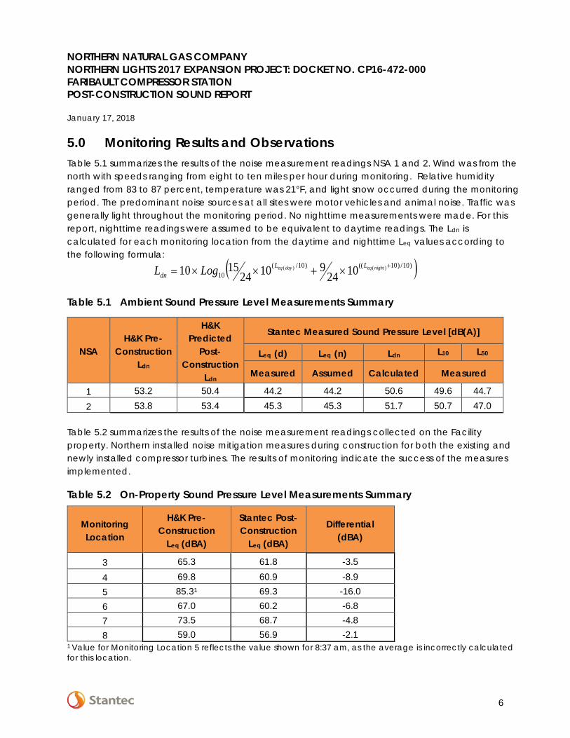
5.0 Monitoring Results and Observations Table 5.1 summarizes the results of the noise measurement readings NSA 1 and 2. Wind was from the north with speeds ranging from eight to ten miles per hour during monitoring. Relative humidity ranged from 83 to 87 percent, temperature was 21°F, and light snow occurred during the monitoring period. The predominant noise sources at all sites were motor vehicles and animal noise. Traffic was generally light throughout the monitoring period. No nighttime measurements were made. For this report, nighttime readings were assumed to be equivalent to daytime readings. The Ldn is calculated for each monitoring location from the daytime and nighttime Leq values according to the following formula:
Table 5.1 Ambient Sound Pressure Level Measurements Summary
NSA H&K Pre-
Construction Ldn
H&K Predicted
Post-Construction
Ldn
Stantec Measured Sound Pressure Level [dB(A)]
Leq (d) Leq (n) Ldn L10 L50
Measured Assumed Calculated Measured
1 53.2 50.4 44.2 44.2 50.6 49.6 44.7 2 53.8 53.4 45.3 45.3 51.7 50.7 47.0
Table 5.2 summarizes the results of the noise measurement readings collected on the Facility property. Northern installed noise mitigation measures during construction for both the existing and newly installed compressor turbines. The results of monitoring indicate the success of the measures implemented.
Table 5.2 On-Property Sound Pressure Level Measurements Summary
1 Value for Monitoring Location 5 reflects the value shown for 8:37 am, as the average is incorrectly calculated for this location.
Monitoring Location
H&K Pre-Construction
Leq (dBA)
Stantec Post-Construction
Leq (dBA)
Differential (dBA)
3 65.3 61.8 -3.5
4 69.8 60.9 -8.9 5 85.31 69.3 -16.0 6 67.0 60.2 -6.8 7 73.5 68.7 -4.8 8 59.0 56.9 -2.1
( ))10/)10(()10/(10
)()( 102491024
1510 +×+××= nighteqdayeq LLdn LogL
NORTHERN NATURAL GAS COMPANY NORTHERN LIGHTS 2017 EXPANSION PROJECT: DOCKET NO. CP16-472-000 FARIBAULT COMPRESSOR STATION POST-CONSTRUCTION SOUND REPORT
January 17, 2018
7
6.0 Conclusions The results of the post-construction sound survey performed on December 21, 2017 indicate that the sound attributable to the Facility at the nearby NSAs with the compressor turbines at operational capacity is less than the Ldn limit of 55 dB(A), which is the sound level specified by the FERC. The compressor station also abides by the MPCA noise level requirements for a compressor station as the measured L10 and L50 were less than residential (NAC-1) requirements for nighttime, which are 55 and 50 dBA respectively.
Page 1 1/17/2018
Northern Natural Gas - Faribault Compressor Station: Post-Construction MonitoringNorthern Lights 2017 Expansion Project: Docket No. CP16-472-000Faribault, Minnesota Compressor StationDecember 21, 2017
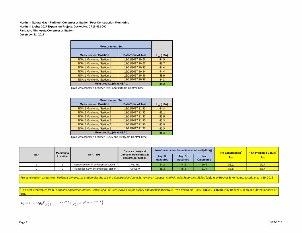
Measurement Position Date/Time of TestNSA 1 Monitoring Station 1 12/21/2017 10:26 44.5NSA 1 Monitoring Station 1 12/21/2017 10:27 43.7NSA 1 Monitoring Station 1 12/21/2017 10:32 44.4NSA 1 Monitoring Station 1 12/21/2017 10:34 44.4NSA 1 Monitoring Station 1 12/21/2017 10:36 43.9NSA 1 Monitoring Station 1 12/21/2017 10:38 44.3
44.2Data was collected between 9:20 and 9:40 am Central Time
Measurement Position Date/Time of TestNSA 2 Monitoring Station 2 12/21/2017 11:31 44.8NSA 2 Monitoring Station 2 12/21/2017 11:32 45.1NSA 2 Monitoring Station 2 12/21/2017 11:33 45.9NSA 2 Monitoring Station 2 12/21/2017 11:35 45.3NSA 2 Monitoring Station 2 12/21/2017 11:36 45.0NSA 2 Monitoring Station 2 12/21/2017 11:37 45.5
45.3Data was collected between 10:25 and 10:45 am Central Time
Leq (d) Measured
Leq (n) Assumed
Ldn
Calculated1 1 Residence NW of compressor station 1,080 NW 44.2 44.2 50.6 53.2 50.42 2 Residences SSW of compressor station 720 SSW 45.3 45.3 51.7 53.8 53.4
1Pre-construction values from Faribault Compressor Station: Results of a Pre-Construction Sound Survey and Accoustial Analysis, H&K Report No. 3390 , Table A by Hoover & Keith, Inc. dated January 19, 2016
2H&K predicted values from Faribault Compressor Station: Results of a Pre-Construction Sound Survey and Accoustial Analysis, H&K Report No. 3390 , Table D, Column 7 by Hoover & Keith, Inc. dated January 19, 2016
Measurement Set
Leq (dBA)
Measured Leq(d) at NSA 1
Measurement SetLeq (dBA)
Pre-Construction1
Ldn
H&K Predicted Values2
Ldn
Measured Leq(d) at NSA 2
NSA Monitoring Location NSA TYPE
Distance (feet) and Direction from Faribault
Compressor Station
Post-Construction Sound Pressure Level [dB(A)]
( ))10/)10(()10/(10
)()( 102491024
1510 +×+××= nighteqdayeq LLdn LogL
Page 2 1/17/2018
Northern Natural Gas - Faribault Compressor Station: Post-Construction MonitoringNorthern Lights 2017 Expansion Project: Docket No. CP16-472-000Faribault, Minnesota Compressor StationDecember 21, 2017
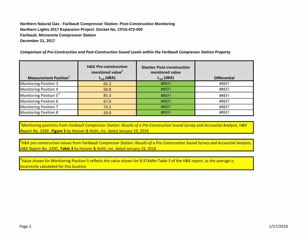
Comparison of Pre-Construction and Post-Construction Sound Levels within the Faribault Compressor Station Property
Monitoring Position 3 65.3 #REF! #REF!Monitoring Position 4 69.8 #REF! #REF!Monitoring Position 53 85.3 #REF! #REF!Monitoring Position 6 67.0 #REF! #REF!Monitoring Position 7 73.5 #REF! #REF!Monitoring Position 8 59.0 #REF! #REF!
3Value shown for Monitoring Position 5 reflects the value shown for 8:37AMin Table 3 of the H&K report, as the average is incorrectly calculated for this location.
2H&K pre-construction values from Faribault Compressor Station: Results of a Pre-Construction Sound Survey and Accoustial Analysis, H&K Report No. 3390 , Table 3 by Hoover & Keith, Inc. dated January 19, 2016
H&K Pre-construction monitored value2
Leq (dBA)Measurement Position1
Stantec Post-construction monitored value
Leq (dBA) Differential
1Monitoring positions from Faribault Compressor Station: Results of a Pre-Construction Sound Survey and Accoustial Analysis, H&K Report No. 3390 , Figure 3 by Hoover & Keith, Inc. dated January 19, 2016
FARIBAULT COMPRESSOR STATION
(RICE COUNTY, MINNESOTA)
RESULTS OF A PRE-CONSTRUCTION SOUND SURVEY AND
ACOUSTICAL ANALYSIS OF A COMPRESSOR ADDITION
ASSOCIATED WITH THE PROPOSED NORTHERN
NATURAL NORTHERN LIGHTS 2017 PROJECT H&K Report No. 3390 H&K Job No. 4946 Date of Report: January 19, 2016 Prepared for: Merjent TractorWorks Building Minneapolis, MN Project Applicant: Northern Natural Gas Company, LLC (“NNG” or “Northern Natural”)
A Berkshire Hathaway Energy Company Submitted by: Paul D. Kiteck, P.E. (primary author) Hoover & Keith Inc.
Hoover & Keith Inc. Consultants in Acoustics and Noise Control Engineering TX Office: 11381 Meadowglen, Suite I; Houston, TX 77082 TX Office Phone: (281) 496-9876 CO Office: 1680 Northwestern Road; Longmont, CO 80503 CO Office Phone: (303) 834-9455
Hoover & Keith Inc. Merjent – Northern Natural Faribault Compressor Station (“Station”) H&K Job No. 4846 Results of Ambient Sound Survey & Acoustical Analysis of the Station H&K Report No. 3390 (Date: 01/19/16)
-Page i-
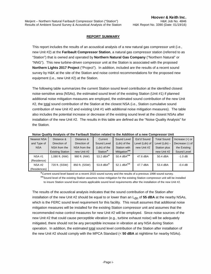
REPORT SUMMARY This report includes the results of an acoustical analysis of a new natural gas compressor unit (i.e., new Unit #2) at the Faribault Compressor Station, a natural gas compressor station (referred to as “Station”) that is owned and operated by Northern Natural Gas Company (“Northern Natural” or “NNG”). This new turbine-driven compressor unit at the Station is associated with the proposed Northern Lights 2017 Project (“Project”). In addition, included are the results of a recent sound survey by H&K at the site of the Station and noise control recommendations for the proposed new equipment (i.e., new Unit #2) at the Station.
The following table summarizes the current Station sound level contribution at the identified closest noise-sensitive area (NSAs), the estimated sound level of the existing Station (Unit #1) if planned additional noise mitigation measures are employed, the estimated sound contribution of the new Unit #2, the total sound contribution of the Station at the closest NSA (i.e., Station cumulative sound contribution of new Unit #2 and existing Unit #1 with additional noise mitigation measures). The table also includes the potential increase or decrease of the existing sound level at the closest NSAs after installation of the new Unit #2. The results in this table are defined as the “Noise Quality Analysis” for the Station.
Noise Quality Analysis of the Faribault Station related to the Addition of a new Compressor Unit
Nearest NSA and Type of
NSA
Distance & Direction of
NSA from the Existing Station
Distance & Direction of
NSA from the new Unit #2
Current Sound Level (Ldn) of the
Station*
Sound Level (Ldn) of the Station with Mitigation**
Est’d Sound Level (Ldn) of new Unit #2
Total Sound Level (Ldn) – Station plus new Unit #2
Increase (+) or Decrease (-) of
the Existing Sound Level
NSA #1 (Residence)
1,080 ft. (NW) 980 ft. (NW) 53.2 dBA* 50.4 dBA** 47.6 dBA 50.4 dBA -1.0 dB
NSA #2 (Residences)
720 ft. (SSW) 850 ft. (SSW) 53.8 dBA* 52.1 dBA** 47.7 dBA 53.4 dBA -0.4 dB
*Current sound level based on a recent 2015 sound survey and the results of a previous 1998 sound survey. **Sound level of the existing Station assumes noise mitigation for the existing Station compressor unit will be installed to insure Station sound level meets applicable sound level requirements after the installation of the new Unit #2.
The results of the acoustical analysis indicates that the sound contribution of the Station after installation of the new Unit #2 should be equal to or lower than an Ldn of 55 dBA at the nearby NSAs, which is the FERC sound level requirement for this facility. This result assumes that additional noise mitigation measures will be installed for the existing Station compressor unit and assumes that the recommended noise control measures for new Unit #2 will be employed. Since noise sources of the new Unit #2 that could cause perceptible vibration (e.g., turbine exhaust noise) will be adequately mitigated, there should not be any perceptible increase in vibration at any NSA during Station operation. In addition, the estimated total sound level contribution of the Station after installation of the new Unit #2 should comply with the MPCA Standard (< 50 dBA at nighttime for nearby NSAs).
Hoover & Keith Inc. Merjent – Northern Natural Faribault Compressor Station (“Station”) H&K Job No. 4846 Results of Ambient Sound Survey & Acoustical Analysis of the Station H&K Report No. 3390 (Date: 01/19/16)
-Page ii-
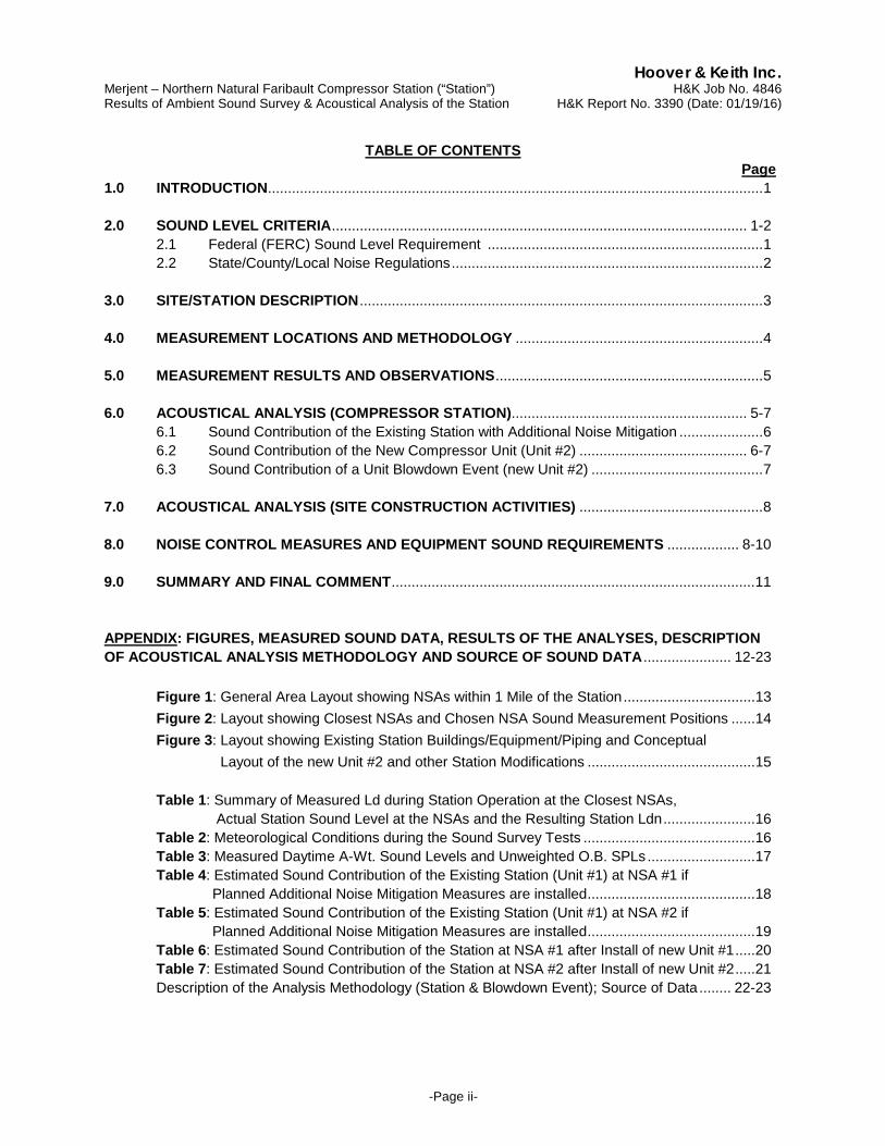
TABLE OF CONTENTS Page 1.0 INTRODUCTION ............................................................................................................................ 1 2.0 SOUND LEVEL CRITERIA ........................................................................................................ 1-2
2.1 Federal (FERC) Sound Level Requirement ..................................................................... 1 2.2 State/County/Local Noise Regulations .............................................................................. 2
3.0 SITE/STATION DESCRIPTION ..................................................................................................... 3 4.0 MEASUREMENT LOCATIONS AND METHODOLOGY .............................................................. 4 5.0 MEASUREMENT RESULTS AND OBSERVATIONS ................................................................... 5 6.0 ACOUSTICAL ANALYSIS (COMPRESSOR STATION)........................................................... 5-7
6.1 Sound Contribution of the Existing Station with Additional Noise Mitigation ..................... 6 6.2 Sound Contribution of the New Compressor Unit (Unit #2) .......................................... 6-7
6.3 Sound Contribution of a Unit Blowdown Event (new Unit #2) ........................................... 7 7.0 ACOUSTICAL ANALYSIS (SITE CONSTRUCTION ACTIVITIES) .............................................. 8 8.0 NOISE CONTROL MEASURES AND EQUIPMENT SOUND REQUIREMENTS .................. 8-10 9.0 SUMMARY AND FINAL COMMENT ........................................................................................... 11 APPENDIX: FIGURES, MEASURED SOUND DATA, RESULTS OF THE ANALYSES, DESCRIPTION OF ACOUSTICAL ANALYSIS METHODOLOGY AND SOURCE OF SOUND DATA ...................... 12-23 Figure 1: General Area Layout showing NSAs within 1 Mile of the Station ................................. 13 Figure 2: Layout showing Closest NSAs and Chosen NSA Sound Measurement Positions ...... 14 Figure 3: Layout showing Existing Station Buildings/Equipment/Piping and Conceptual Layout of the new Unit #2 and other Station Modifications .......................................... 15 Table 1: Summary of Measured Ld during Station Operation at the Closest NSAs, Actual Station Sound Level at the NSAs and the Resulting Station Ldn ....................... 16
Table 2: Meteorological Conditions during the Sound Survey Tests ........................................... 16 Table 3: Measured Daytime A-Wt. Sound Levels and Unweighted O.B. SPLs ........................... 17
Table 4: Estimated Sound Contribution of the Existing Station (Unit #1) at NSA #1 if Planned Additional Noise Mitigation Measures are installed .......................................... 18 Table 5: Estimated Sound Contribution of the Existing Station (Unit #1) at NSA #2 if Planned Additional Noise Mitigation Measures are installed .......................................... 19 Table 6: Estimated Sound Contribution of the Station at NSA #1 after Install of new Unit #1 ..... 20 Table 7: Estimated Sound Contribution of the Station at NSA #2 after Install of new Unit #2 ..... 21 Description of the Analysis Methodology (Station & Blowdown Event); Source of Data ........ 22-23
Hoover & Keith Inc. Merjent – Northern Natural Faribault Compressor Station (“Station”) H&K Job No. 4846 Results of Ambient Sound Survey & Acoustical Analysis of the Station H&K Report No. 3390 (Date: 01/19/16)
-Page 1-
1.0 INTRODUCTION
In this report, Hoover & Keith Inc. (H&K) presents the results of an acoustical analysis of a new gas compressor unit (i.e., new Unit #2) at the Faribault Compressor Station, a natural gas compressor station (referred to as “Station”) that is owned and operated by Northern Natural Gas Company (“Northern Natural” or “NNG”). This new turbine-driven compressor unit at the Station is associated with the proposed Northern Lights 2017 Project (“Project”). In addition, the results of a recent sound survey by H&K during Station operation are included. The following describes the purpose of the pre-construction sound survey and included acoustical analyses:
(1) The acoustical analysis estimates the Station sound contribution at nearby noise-sensitive
areas (NSAs), such as residences, hospitals and schools, which would result from the new compressor unit and determine noise mitigation measures to insure that applicable sound level criteria are not exceeded after installation of the new compressor unit;
(2) The recent sound survey quantifies the current Station sound level during operation at the
identified nearest NSAs. At one (1) of the NSAs (NSA #2), the results of a previous sound survey1 was utilized to obtain a representative Station sound contribution at that NSA;
(3) In addition, the sound level resulting from construction activities at the Station site and the
sound level due to a blowdown event for the new compressor unit were estimated. 2.0 SOUND LEVEL CRITERIA 2.1 Federal (FERC) Sound Level Requirement
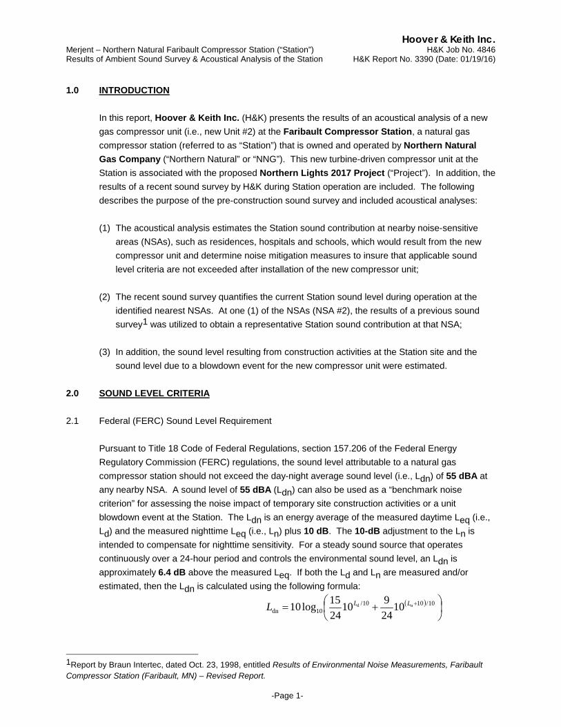
Pursuant to Title 18 Code of Federal Regulations, section 157.206 of the Federal Energy Regulatory Commission (FERC) regulations, the sound level attributable to a natural gas compressor station should not exceed the day-night average sound level (i.e., Ldn) of 55 dBA at any nearby NSA. A sound level of 55 dBA (Ldn) can also be used as a “benchmark noise criterion” for assessing the noise impact of temporary site construction activities or a unit blowdown event at the Station. The Ldn is an energy average of the measured daytime Leq (i.e., Ld) and the measured nighttime Leq (i.e., Ln) plus 10 dB. The 10-dB adjustment to the Ln is intended to compensate for nighttime sensitivity. For a steady sound source that operates continuously over a 24-hour period and controls the environmental sound level, an Ldn is approximately 6.4 dB above the measured Leq. If both the Ld and Ln are measured and/or estimated, then the Ldn is calculated using the following formula:
( )
+= + 10/1010/
10dnnd 10
24910
2415log10 LLL
1Report by Braun Intertec, dated Oct. 23, 1998, entitled Results of Environmental Noise Measurements, Faribault Compressor Station (Faribault, MN) – Revised Report.
Hoover & Keith Inc. Merjent – Northern Natural Faribault Compressor Station (“Station”) H&K Job No. 4846 Results of Ambient Sound Survey & Acoustical Analysis of the Station H&K Report No. 3390 (Date: 01/19/16)
-Page 2-
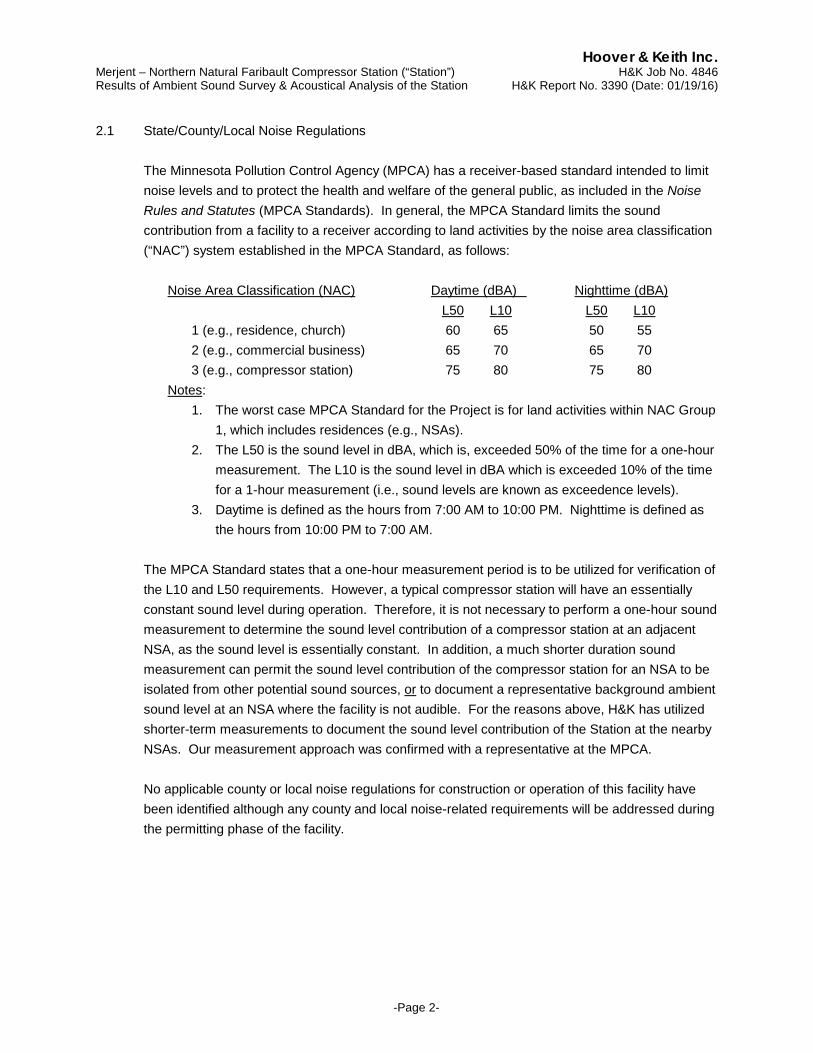
2.1 State/County/Local Noise Regulations The Minnesota Pollution Control Agency (MPCA) has a receiver-based standard intended to limit noise levels and to protect the health and welfare of the general public, as included in the Noise Rules and Statutes (MPCA Standards). In general, the MPCA Standard limits the sound contribution from a facility to a receiver according to land activities by the noise area classification (“NAC”) system established in the MPCA Standard, as follows:
Noise Area Classification (NAC) Daytime (dBA) Nighttime (dBA)
L50 L10 L50 L10 1 (e.g., residence, church) 60 65 50 55 2 (e.g., commercial business) 65 70 65 70 3 (e.g., compressor station) 75 80 75 80
Notes: 1. The worst case MPCA Standard for the Project is for land activities within NAC Group
1, which includes residences (e.g., NSAs). 2. The L50 is the sound level in dBA, which is, exceeded 50% of the time for a one-hour
measurement. The L10 is the sound level in dBA which is exceeded 10% of the time for a 1-hour measurement (i.e., sound levels are known as exceedence levels).
3. Daytime is defined as the hours from 7:00 AM to 10:00 PM. Nighttime is defined as the hours from 10:00 PM to 7:00 AM.
The MPCA Standard states that a one-hour measurement period is to be utilized for verification of the L10 and L50 requirements. However, a typical compressor station will have an essentially constant sound level during operation. Therefore, it is not necessary to perform a one-hour sound measurement to determine the sound level contribution of a compressor station at an adjacent NSA, as the sound level is essentially constant. In addition, a much shorter duration sound measurement can permit the sound level contribution of the compressor station for an NSA to be isolated from other potential sound sources, or to document a representative background ambient sound level at an NSA where the facility is not audible. For the reasons above, H&K has utilized shorter-term measurements to document the sound level contribution of the Station at the nearby NSAs. Our measurement approach was confirmed with a representative at the MPCA. No applicable county or local noise regulations for construction or operation of this facility have been identified although any county and local noise-related requirements will be addressed during the permitting phase of the facility.
Hoover & Keith Inc. Merjent – Northern Natural Faribault Compressor Station (“Station”) H&K Job No. 4846 Results of Ambient Sound Survey & Acoustical Analysis of the Station H&K Report No. 3390 (Date: 01/19/16)
-Page 3-
3.0 STATION/SITE DESCRIPTION
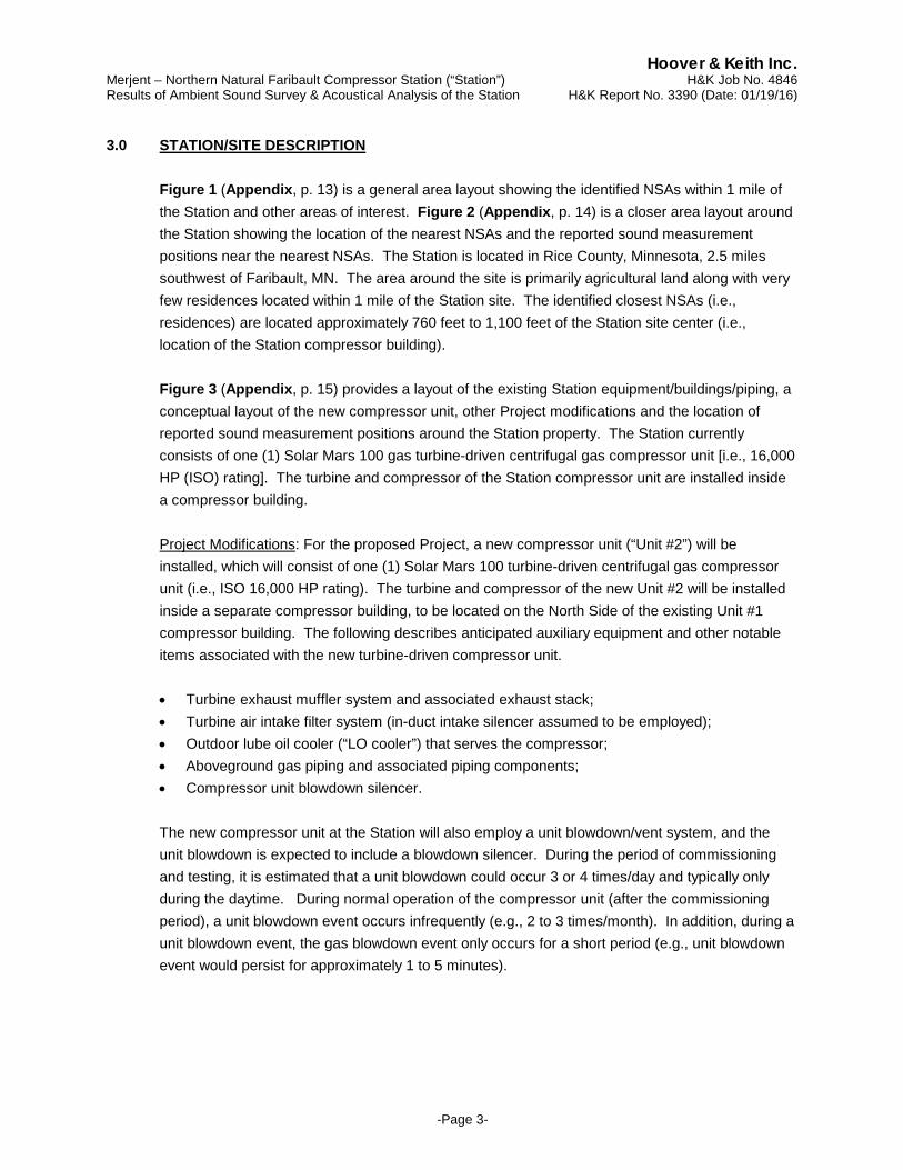
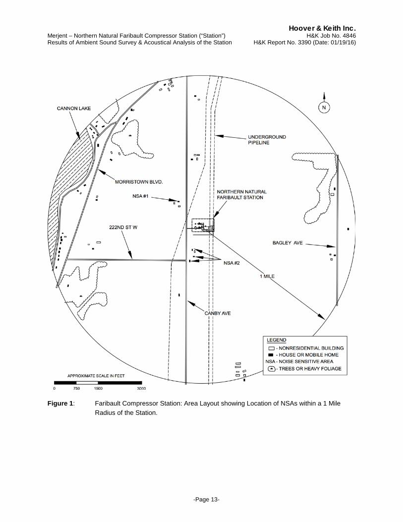
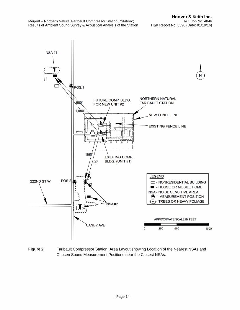
Figure 1 (Appendix, p. 13) is a general area layout showing the identified NSAs within 1 mile of the Station and other areas of interest. Figure 2 (Appendix, p. 14) is a closer area layout around the Station showing the location of the nearest NSAs and the reported sound measurement positions near the nearest NSAs. The Station is located in Rice County, Minnesota, 2.5 miles southwest of Faribault, MN. The area around the site is primarily agricultural land along with very few residences located within 1 mile of the Station site. The identified closest NSAs (i.e., residences) are located approximately 760 feet to 1,100 feet of the Station site center (i.e., location of the Station compressor building).
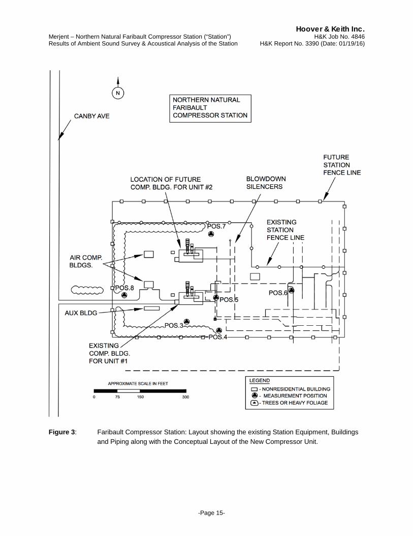
Figure 3 (Appendix, p. 15) provides a layout of the existing Station equipment/buildings/piping, a conceptual layout of the new compressor unit, other Project modifications and the location of reported sound measurement positions around the Station property. The Station currently consists of one (1) Solar Mars 100 gas turbine-driven centrifugal gas compressor unit [i.e., 16,000 HP (ISO) rating]. The turbine and compressor of the Station compressor unit are installed inside a compressor building. Project Modifications: For the proposed Project, a new compressor unit (“Unit #2”) will be installed, which will consist of one (1) Solar Mars 100 turbine-driven centrifugal gas compressor unit (i.e., ISO 16,000 HP rating). The turbine and compressor of the new Unit #2 will be installed inside a separate compressor building, to be located on the North Side of the existing Unit #1 compressor building. The following describes anticipated auxiliary equipment and other notable items associated with the new turbine-driven compressor unit.
• Turbine exhaust muffler system and associated exhaust stack; • Turbine air intake filter system (in-duct intake silencer assumed to be employed); • Outdoor lube oil cooler (“LO cooler”) that serves the compressor; • Aboveground gas piping and associated piping components; • Compressor unit blowdown silencer.
The new compressor unit at the Station will also employ a unit blowdown/vent system, and the unit blowdown is expected to include a blowdown silencer. During the period of commissioning and testing, it is estimated that a unit blowdown could occur 3 or 4 times/day and typically only during the daytime. During normal operation of the compressor unit (after the commissioning period), a unit blowdown event occurs infrequently (e.g., 2 to 3 times/month). In addition, during a unit blowdown event, the gas blowdown event only occurs for a short period (e.g., unit blowdown event would persist for approximately 1 to 5 minutes).

Hoover & Keith Inc. Merjent – Northern Natural Faribault Compressor Station (“Station”) H&K Job No. 4846 Results of Ambient Sound Survey & Acoustical Analysis of the Station H&K Report No. 3390 (Date: 01/19/16)
-Page 4-
4.0 MEASUREMENT LOCATIONS, CONDITIONS AND METHODOLOGY Sound survey measurements around the Station during operation were performed by Garrett
Porter of H&K during the daytime of Dec. 17, 2015, which included verification of existing NSAs surrounding the Station within approximately 1 mile of the Station site. During the sound survey tests, the temperature was 29 F, with cloudy skies and relatively high wind conditions from the west. The following is a description of the identified closest NSAs and the reported sound measurement positions during the recent sound survey at the closest NSAs and around the Station property: Pos. 1: Near NSA #1; Residence along West Side of Canby Ave., located approximately 1,080
feet northwest (NW) of the Station site center (i.e., location of the Station compressor building) and approximately 980 ft. NW of the new compressor unit (i.e., compressor building for new Unit #2);
Pos. 2: Near NSA #2; Residences along East Side of Canby Ave., and the closest of these
residences is located approximately 720 feet south-southwest (SSW) of the Station site center and approximately 850 ft. SSW of new Unit #2;
Pos. 3: Approximately 50 ft. south of the Station compressor building; Pos. 4: Approximately 85 ft. southeast (SE) of the Station compressor building; Pos. 5: Approximately 30 ft. east of the Station compressor building (area of piping); Pos. 6: Approximately 275 ft. east of the Station compressor building; Pos. 7: Approximately 195 ft. north of the Station compressor building; and Pos. 8: Approximately 180 ft. west of the Station compressor building.
At the reported sound measurement positions near the nearby NSAs, the A-weighted (A-wt.) sound level (i.e., Leq) and the unweighted octave-band (O.B.) sound pressure levels (i.e., Leq SPLs) were measured at 5 feet above ground. The sound measurements attempted to exclude "extraneous and intermittent sound" such as a vehicle passing immediately by the sound measurement location. In addition, the sound measurements were conducted during a period when the wind speed was below 8 mph, if feasible, although at one of the identified nearby NSAs (i.e., NSA #2), the wind-related noise was dominant and unavoidable. The acoustical measurement system consisted of a Norsonic Model Nor140 Sound Level Meter (a Type 1 “SLM” per ANSI S1.4 & S1.11) equipped with a ½-inch condenser microphone with a windscreen. The SLM was calibrated with a microphone calibrator (calibrated within 1 year of the sound test date).

Hoover & Keith Inc. Merjent – Northern Natural Faribault Compressor Station (“Station”) H&K Job No. 4846 Results of Ambient Sound Survey & Acoustical Analysis of the Station H&K Report No. 3390 (Date: 01/19/16)
-Page 5-
5.0 MEASUREMENT RESULTS AND OBSERVATIONS
Table 1 (Appendix, p. 16) shows the measured daytime Leq (i.e., Ld) at each reported NSA sound measurement position along with the average of the measured Ld (i.e., since more than 1 test was typically performed). The resulting Ldn are also provided in Table A, as calculated from the measured Ld, and the “actual” Station sound level at NSA #2 based on a previous 1998 sound survey since H&K’s sound level data at NSA #2 (per recent Dec. 2015 sound survey) was not representative of actual Station sound contribution. Meteorological conditions during the recent sound survey are summarized in Table 2 (Appendix, p. 16). The measured/averaged A-wt. sound levels (Ld) and the associated unweighted O.B. SPLs at the all reported sound measurement positions are provided in Table 3 (Appendix, p. 17). The following Table A summarizes the measured Ld during the recent Dec. 2015 sound survey at the closest NSAs with the Station operating at full load along with the resulting Ldn (i.e., as calculated via the measured Ld). In addition, since the wind-related noise significantly influenced the measured sound levels at NSA #2, the “actual” Station sound level contribution (Ldn) at NSA #2 was included, based on a previous 1998 sound survey.
Meas. Pos.
Description of Sound Measurement Location And associated NSA
Measured Ld
Resulting Ldn
“Actual” Station Ldn
Pos. 1 NSA #1: Residence 1,080 ft. NW of CS site center 46.8 dBA 53.2 dBA 53.2 dBA Pos. 2 NSA #2: Residences 720 ft. SSW of CS site center 60.3 dBA 66.7 dBA 53.8 dBA
Table A: Summary of Measured Ld during Station Operation and the Resulting Ldn at the NSA Sound Measurement Positions along with the “Actual” Station Sound Level (Ldn) at the Closest NSAs.
During the sound measurements by H&K near NSA #1, the Station noise was the most significant and dominant noise source although there was also some noise of distant vehicle traffic along local roads, and at times, wind-related sound (sound of wind blowing in local foliage/trees). During the sound level measurements by H&K near NSA #2, wind-related sound was the dominant noise source although there was some audible low-frequency noise associated with the Station turbine. Therefore, the actual Station sound level at NSA #2 should be significantly lower than the measured sound level at NSA #2 during the Dec. 2015 sound survey by H&K. As a result, the measured Station Ldn during a previous 1998 sound survey was utilized to provide a more representative of the actual Station sound level contribution at NSA #2.
6.0 ACOUSTICAL ANALYSIS (COMPRESSOR STATION)
The following section addresses the sound level contribution of the new Unit #2 during full load operation. In addition, there is a need to estimate the sound level contribution of the existing Station compressor unit (Unit #1) assuming planned noise mitigation measures are employed (i.e., acoustical insulation for the existing aboveground gas piping). Also included is an estimate of the unit blowdown noise associated with the new Unit #2 that occurs occasionally.
Hoover & Keith Inc. Merjent – Northern Natural Faribault Compressor Station (“Station”) H&K Job No. 4846 Results of Ambient Sound Survey & Acoustical Analysis of the Station H&K Report No. 3390 (Date: 01/19/16)
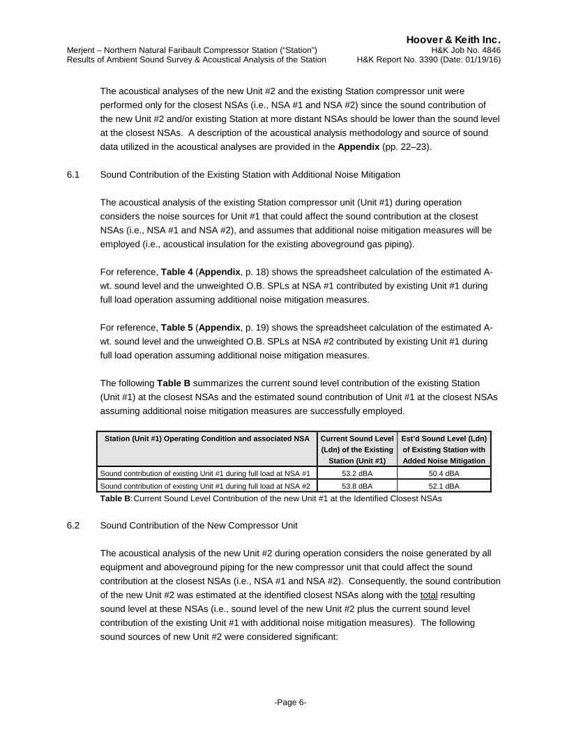
-Page 6-
The acoustical analyses of the new Unit #2 and the existing Station compressor unit were performed only for the closest NSAs (i.e., NSA #1 and NSA #2) since the sound contribution of the new Unit #2 and/or existing Station at more distant NSAs should be lower than the sound level at the closest NSAs. A description of the acoustical analysis methodology and source of sound data utilized in the acoustical analyses are provided in the Appendix (pp. 22–23).
6.1 Sound Contribution of the Existing Station with Additional Noise Mitigation
The acoustical analysis of the existing Station compressor unit (Unit #1) during operation considers the noise sources for Unit #1 that could affect the sound contribution at the closest NSAs (i.e., NSA #1 and NSA #2), and assumes that additional noise mitigation measures will be employed (i.e., acoustical insulation for the existing aboveground gas piping).
For reference, Table 4 (Appendix, p. 18) shows the spreadsheet calculation of the estimated A-wt. sound level and the unweighted O.B. SPLs at NSA #1 contributed by existing Unit #1 during full load operation assuming additional noise mitigation measures.
For reference, Table 5 (Appendix, p. 19) shows the spreadsheet calculation of the estimated A-wt. sound level and the unweighted O.B. SPLs at NSA #2 contributed by existing Unit #1 during full load operation assuming additional noise mitigation measures.
The following Table B summarizes the current sound level contribution of the existing Station (Unit #1) at the closest NSAs and the estimated sound contribution of Unit #1 at the closest NSAs assuming additional noise mitigation measures are successfully employed.
Station (Unit #1) Operating Condition and associated NSA Current Sound Level
(Ldn) of the Existing Station (Unit #1)
Est’d Sound Level (Ldn) of Existing Station with Added Noise Mitigation
Sound contribution of existing Unit #1 during full load at NSA #1 53.2 dBA 50.4 dBA Sound contribution of existing Unit #1 during full load at NSA #2 53.8 dBA 52.1 dBA Table B: Current Sound Level Contribution of the new Unit #1 at the Identified Closest NSAs
6.2 Sound Contribution of the New Compressor Unit
The acoustical analysis of the new Unit #2 during operation considers the noise generated by all equipment and aboveground piping for the new compressor unit that could affect the sound contribution at the closest NSAs (i.e., NSA #1 and NSA #2). Consequently, the sound contribution of the new Unit #2 was estimated at the identified closest NSAs along with the total resulting sound level at these NSAs (i.e., sound level of the new Unit #2 plus the current sound level contribution of the existing Unit #1 with additional noise mitigation measures). The following sound sources of new Unit #2 were considered significant:
Hoover & Keith Inc. Merjent – Northern Natural Faribault Compressor Station (“Station”) H&K Job No. 4846 Results of Ambient Sound Survey & Acoustical Analysis of the Station H&K Report No. 3390 (Date: 01/19/16)
-Page 7-
• Noise generated by the turbine/compressor that penetrates the compressor building; • Turbine exhaust noise (i.e., noise source that could generate perceptible vibration); • Noise radiated from aboveground gas piping and associated components; • Noise of the LO cooler; • Noise generated by the turbine air intake system; and • Noise radiated from the outdoor turbine exhaust ducting and any expansion joint.
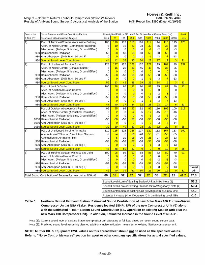
Table 6 (Appendix, p. 20) shows the spreadsheet calculation of the estimated A-wt. sound level and the unweighted O.B. SPLs at NSA #1 contributed by the new Unit #2 during full load operation assuming standard day conditions (i.e., no wind, 60 deg. F. and 70% R.H.). The acoustical analysis includes the effect of the anticipated and/or recommended noise control measures for the new Unit #2 equipment. Also included in Table 6 is the estimated total sound level at NSA #1 (i.e., sound level contribution of the new Unit #2 plus Unit #1 sound level with additional noise mitigation).
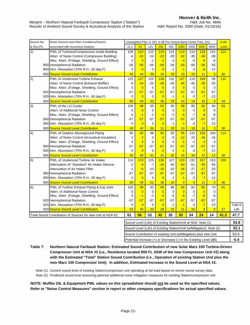
Table 7 (Appendix, p. 21) shows the spreadsheet calculation of the estimated A-wt. sound level and the unweighted O.B. SPLs at NSA #2 contributed by the new Unit #2 during full load operation assuming standard day conditions (i.e., no wind, 60 deg. F. and 70% R.H.). The acoustical analysis includes the effect of the anticipated and/or recommended noise control measures for the new Unit #2 equipment. Also included in Table 7 is the estimated total sound level at NSA #2 (i.e., sound level contribution of the new Unit #2 plus Unit #1 sound level with additional noise mitigation).
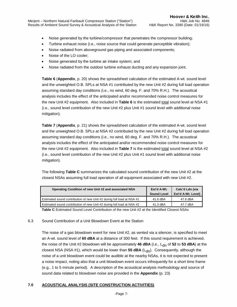
The following Table C summarizes the calculated sound contribution of the new Unit #2 at the closest NSAs assuming full load operation of all equipment associated with new Unit #2.
Operating Condition of new Unit #2 and associated NSA Est’d A-Wt.
Sound Level Calc’d Ldn (via
Est’d A-Wt. Level) Estimated sound contribution of new Unit #2 during full load at NSA #1 41.6 dBA 47.6 dBA Estimated sound contribution of new Unit #2 during full load at NSA #2 41.3 dBA 47.7 dBA Table C: Estimated Sound Level Contribution of the new Unit #2 at the Identified Closest NSAs
6.3 Sound Contribution of a Unit Blowdown Event at the Station
The noise of a gas blowdown event for new Unit #2, as vented via a silencer, is specified to meet an A-wt. sound level of 60 dBA at a distance of 300 feet. If this sound requirement is achieved, the noise of the Unit #2 blowdown will be approximately 46 dBA (i.e., Ldn of 52 to 53 dBA) at the closest NSA (NSA #1), which would be lower than 55 dBA (Ldn). Consequently, although the noise of a unit blowdown event could be audible at the nearby NSAs, it is not expected to present a noise impact, noting also that a unit blowdown event occurs infrequently for a short time frame (e.g., 1 to 5 minute period). A description of the acoustical analysis methodology and source of sound data related to blowdown noise are provided in the Appendix (p. 23)
7.0 ACOUSTICAL ANALYSIS (SITE CONSTRUCTION ACTIVITIES)

Hoover & Keith Inc. Merjent – Northern Natural Faribault Compressor Station (“Station”) H&K Job No. 4846 Results of Ambient Sound Survey & Acoustical Analysis of the Station H&K Report No. 3390 (Date: 01/19/16)
-Page 8-
The most prevalent sound source during construction will be internal combustion engines used to power construction equipment. Construction of the new compressor unit would consist of some earthwork (e.g., site grading, clearing and grubbing related to construction of the new buildings). Construction activities will be performed with standard heavy equipment such as a track-excavator, backhoe, dump truck(s) and concrete truck(s). Many construction machines operate intermittently and the types of machines in use at a construction site changes with the construction phase. The noise level contribution of construction-related activities at the Station related to the installation of the new compressor unit is not expected to exceed existing noise levels generated by the Station [i.e., site construction noise should be lower than 55 dBA (Ldn) at the nearby NSAs]. Therefore, site construction noise associated with the installation of the new compressor unit should have a minimal noise impact to the nearby NSAs, noting that the construction will be primarily limited to daytime hours.
8.0 NOISE CONTROL MEASURES AND EQUIPMENT SOUND REQUIREMENTS
The following section provides the recommended noise control measures and equipment sound level requirements for the significant sound sources (i.e., equipment & components) associated with the new compressor unit along with other assumptions that may affect the noise and vibration generated by the new compressor during normal operation.
8.1 Building Enclosing the Turbine/Compressor
Noise control measures will be applied to the building that will enclose the turbine/compressor for new Unit #2 rather than to the equipment themselves. The following describes specific requirements and other items related to the components of this compressor building.
• As a minimum, walls/roof should be constructed with an exterior skin of 22–gauge metal, and
building interior surfaces should be covered with 6–inch thick “high-density” mineral wool (i.e., 6.0-8.0 pcf uniform density) covered with a perforated liner. “Low-density” acoustical and/or thermal-type insulation (e.g., 0.6 to 0.75 pcf density) should not be substituted for the high-density material although low-density insulation could be employed in addition to the high-density insulation;
• The large access door/system (i.e., “roll-up door”) should consist of an insulated-type door
(e.g., 18-ga. exterior facing, 24-ga. backskin with insulation core). Personnel entry doors should be a STC-36 sound rating, even if glazing is employed and should be self-closing and should seal well when closed. No windows or open louvers should be installed in the compressor building walls;
• It is anticipated that the building air ventilation system will be designed with air supply fans
mounted in the building walls along with roof-mounted air exhaust vents or a roof ridge vent to exhaust the air. Assuming this type of air ventilation system, the sound level for each wall air-
Hoover & Keith Inc. Merjent – Northern Natural Faribault Compressor Station (“Station”) H&K Job No. 4846 Results of Ambient Sound Survey & Acoustical Analysis of the Station H&K Report No. 3390 (Date: 01/19/16)
-Page 9-
supply fan should not exceed 50 dBA at 50 feet, which will require that each fan employ an exterior dissipative-type silencer (e.g., 3-ft. length) and acoustically lined weatherhood.
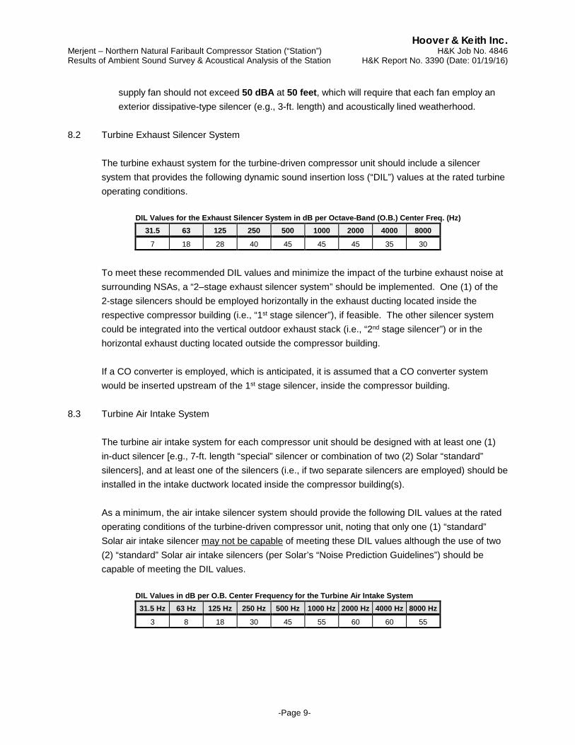
8.2 Turbine Exhaust Silencer System
The turbine exhaust system for the turbine-driven compressor unit should include a silencer system that provides the following dynamic sound insertion loss (“DIL”) values at the rated turbine operating conditions.
DIL Values for the Exhaust Silencer System in dB per Octave-Band (O.B.) Center Freq. (Hz)
31.5 63 125 250 500 1000 2000 4000 8000
7 18 28 40 45 45 45 35 30
To meet these recommended DIL values and minimize the impact of the turbine exhaust noise at surrounding NSAs, a “2–stage exhaust silencer system” should be implemented. One (1) of the 2-stage silencers should be employed horizontally in the exhaust ducting located inside the respective compressor building (i.e., “1st stage silencer”), if feasible. The other silencer system could be integrated into the vertical outdoor exhaust stack (i.e., “2nd stage silencer”) or in the horizontal exhaust ducting located outside the compressor building. If a CO converter is employed, which is anticipated, it is assumed that a CO converter system would be inserted upstream of the 1st stage silencer, inside the compressor building.
8.3 Turbine Air Intake System
The turbine air intake system for each compressor unit should be designed with at least one (1) in-duct silencer [e.g., 7-ft. length “special” silencer or combination of two (2) Solar “standard” silencers], and at least one of the silencers (i.e., if two separate silencers are employed) should be installed in the intake ductwork located inside the compressor building(s). As a minimum, the air intake silencer system should provide the following DIL values at the rated operating conditions of the turbine-driven compressor unit, noting that only one (1) “standard” Solar air intake silencer may not be capable of meeting these DIL values although the use of two (2) “standard” Solar air intake silencers (per Solar’s “Noise Prediction Guidelines”) should be capable of meeting the DIL values. DIL Values in dB per O.B. Center Frequency for the Turbine Air Intake System
31.5 Hz 63 Hz 125 Hz 250 Hz 500 Hz 1000 Hz 2000 Hz 4000 Hz 8000 Hz
3 8 18 30 45 55 60 60 55
Hoover & Keith Inc. Merjent – Northern Natural Faribault Compressor Station (“Station”) H&K Job No. 4846 Results of Ambient Sound Survey & Acoustical Analysis of the Station H&K Report No. 3390 (Date: 01/19/16)
-Page 10-
8.4 Aboveground Gas Piping and Associated Components
The acoustical analysis indicates that noise control measures for the outdoor aboveground gas piping associated with new Unit #2 will be required to meet applicable sound criteria. These same noise mitigation measures should also be applicable for the existing aboveground gas piping at existing Station compressor unit (Unit #1). The following items associated with the gas piping and piping components for new Unit #2 should be addressed:
• Acoustical pipe insulation should be employed for aboveground suction gas piping, discharge
gas piping and any recycle (surge control) gas piping. Acoustical pipe insulation should consist of a minimum 3-inch thick fiberglass or mineral wool (6.0-8.0 pcf density) that is covered with a mass-filled vinyl jacket (e.g., composite of 1.0 psf mass-filled vinyl laminated to 0.020-inch thick aluminum);
• All exposed pipe supports for the insulated gas piping should be covered with acoustical
insulation/cover or a type of removable/reusable acoustical blanket material;
• Outdoor valves should be covered with a type of removable/reusable “tight-fitting” acoustical blanket material. The acoustical blanket material could consist of a core of 2.0-in thick needled fiber mat (6.0-8.0 pcf), a liner material of mass-loaded vinyl (surface weight of 1.0-1.25 psf) covered with a coated fiberglass cloth;
• New or existing filter–separators and related gas piping should not have to be covered with
acoustical material unless deemed necessary after installation of new Unit #2. 8.5 Lube Oil Cooler
Lube oil cooler (“LO cooler”) for the new compressor unit should not exceed 60 dBA at 50 feet from the cooler perimeter at the full rated operating conditions (i.e., equivalent to a PWL of 92–93 dBA), and a “custom” Solar LO cooler may be required to meet the recommended sound level requirement.
8.6 Unit Blowdown Silencer
It is expected that a silencer will be employed for the unit blowdown event, and the unit blowdown silencer should attenuate the unsilenced blowdown noise to a noise level equal to or less than 60 dBA at 300 feet from the outlet of the silencer, which includes the noise radiated from the shell of the silencer during the blowdown event.
Hoover & Keith Inc. Merjent – Northern Natural Faribault Compressor Station (“Station”) H&K Job No. 4846 Results of Ambient Sound Survey & Acoustical Analysis of the Station H&K Report No. 3390 (Date: 01/19/16)
-Page 11-
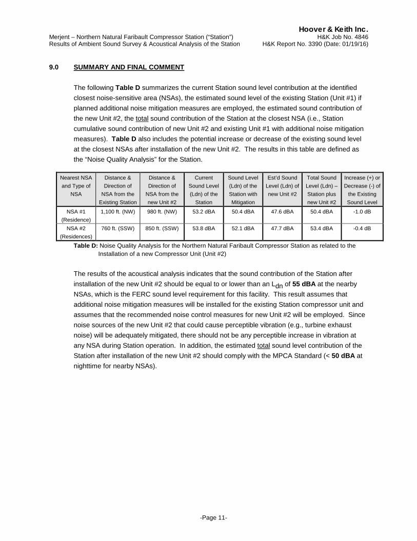
9.0 SUMMARY AND FINAL COMMENT The following Table D summarizes the current Station sound level contribution at the identified closest noise-sensitive area (NSAs), the estimated sound level of the existing Station (Unit #1) if planned additional noise mitigation measures are employed, the estimated sound contribution of the new Unit #2, the total sound contribution of the Station at the closest NSA (i.e., Station cumulative sound contribution of new Unit #2 and existing Unit #1 with additional noise mitigation measures). Table D also includes the potential increase or decrease of the existing sound level at the closest NSAs after installation of the new Unit #2. The results in this table are defined as the “Noise Quality Analysis” for the Station.
Nearest NSA and Type of
NSA
Distance & Direction of
NSA from the Existing Station
Distance & Direction of
NSA from the new Unit #2
Current Sound Level (Ldn) of the
Station
Sound Level (Ldn) of the Station with Mitigation
Est’d Sound Level (Ldn) of new Unit #2
Total Sound Level (Ldn) – Station plus new Unit #2
Increase (+) or Decrease (-) of
the Existing Sound Level
NSA #1 (Residence)
1,100 ft. (NW) 980 ft. (NW) 53.2 dBA 50.4 dBA 47.6 dBA 50.4 dBA -1.0 dB
NSA #2 (Residences)
760 ft. (SSW) 850 ft. (SSW) 53.8 dBA 52.1 dBA 47.7 dBA 53.4 dBA -0.4 dB
Table D: Noise Quality Analysis for the Northern Natural Faribault Compressor Station as related to the Installation of a new Compressor Unit (Unit #2)
The results of the acoustical analysis indicates that the sound contribution of the Station after installation of the new Unit #2 should be equal to or lower than an Ldn of 55 dBA at the nearby NSAs, which is the FERC sound level requirement for this facility. This result assumes that additional noise mitigation measures will be installed for the existing Station compressor unit and assumes that the recommended noise control measures for new Unit #2 will be employed. Since noise sources of the new Unit #2 that could cause perceptible vibration (e.g., turbine exhaust noise) will be adequately mitigated, there should not be any perceptible increase in vibration at any NSA during Station operation. In addition, the estimated total sound level contribution of the Station after installation of the new Unit #2 should comply with the MPCA Standard (< 50 dBA at nighttime for nearby NSAs).
Hoover & Keith Inc. Merjent – Northern Natural Faribault Compressor Station (“Station”) H&K Job No. 4846 Results of Ambient Sound Survey & Acoustical Analysis of the Station H&K Report No. 3390 (Date: 01/19/16)
-Page 12-
APPENDIX
FIGURE 1: GENERAL AREA LAYOUT AROUND THE STATION SHOWING THE NSAs LOCATED WITHIN 1 MILE OF THE STATION
FIGURE 2: LAYOUT AROUND THE STATION
SHOWING THE CLOSEST NSAs AND REPORTED SOUND MEASUREMENT POSITIONS NEAR THE CLOSEST NSAs
FIGURE 3: LAYOUT SHOWING THE EXISTING
EQUIPMENT, BUILDINGS AND PIPING AT THE STATION ALONG WITH A CONCEPTUAL LAYOUT OF THE NEW COMPRESSOR UNIT
SUMMARY OF THE MEASURED SOUND SURVEY DATA AND ANY SUBSEQUENT SOUND DATA CALCULATIONS
ACOUSTICAL ANALYSIS (NEW COMPRESSOR UNIT) ACOUSTICAL ANALYSIS (CONTRUCTION ACTIVITIES
RELATED TO INSTALLATION OF THE NEW UNIT) ANALYSIS METHODOLOGY (NOISE ATTRIBUTABLE TO
THE NEW UNIT, RELATED UNIT BLOWDOWN EVENT AND ANALYSIS OF THE EXISTING UNIT WITH MITIGATION); SOURCE OF SOUND DATA
Hoover & Keith Inc. Merjent – Northern Natural Faribault Compressor Station (“Station”) H&K Job No. 4846 Results of Ambient Sound Survey & Acoustical Analysis of the Station H&K Report No. 3390 (Date: 01/19/16)
-Page 13-
Figure 1: Faribault Compressor Station: Area Layout showing Location of NSAs within a 1 Mile
Radius of the Station.
Hoover & Keith Inc. Merjent – Northern Natural Faribault Compressor Station (“Station”) H&K Job No. 4846 Results of Ambient Sound Survey & Acoustical Analysis of the Station H&K Report No. 3390 (Date: 01/19/16)
-Page 14-
Figure 2: Faribault Compressor Station: Area Layout showing Location of the Nearest NSAs and
Chosen Sound Measurement Positions near the Closest NSAs.
Hoover & Keith Inc. Merjent – Northern Natural Faribault Compressor Station (“Station”) H&K Job No. 4846 Results of Ambient Sound Survey & Acoustical Analysis of the Station H&K Report No. 3390 (Date: 01/19/16)
-Page 15-
Figure 3: Faribault Compressor Station: Layout showing the existing Station Equipment, Buildings
and Piping along with the Conceptual Layout of the New Compressor Unit.
Hoover & Keith Inc. Merjent – Northern Natural Faribault Compressor Station (“Station”) H&K Job No. 4846 Results of Ambient Sound Survey & Acoustical Analysis of the Station H&K Report No. 3390 (Date: 01/19/16)
-Page 16-
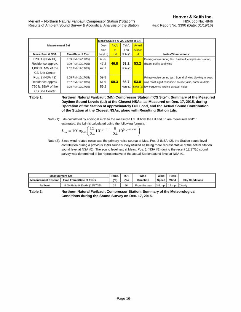
Meas'd/Calc'd A-Wt. Levels (dBA) Measurement Set Day- Avg'd Calc'd Actual
time of Ldn StationMeas. Pos. & NSA Time/Date of Test Leq(Ld) Ld Note (1) Ldn Notes/Observations
Pos. 1 (NSA #1) 8:59 PM (12/17/15) 45.6 Primary noise during test: Faribault compressor station,Residence approx. 9:00 PM (12/17/15) 47.2 46.8 53.2 53.2 distant traffic, and wind1,080 ft. NW of the 9:02 PM (12/17/15) 47.7 Note (1)
CS Site CenterPos. 2 (NSA #2) 9:05 PM (12/17/15) 59.8 Primary noise during test: Sound of wind blowing in trees
Residence approx. 9:07 PM (12/17/15) 61.9 60.3 66.7 53.8 was most significant noise source; also, some audible720 ft. SSW of the 9:08 PM (12/17/15) 59.2 Note (1) Note (2) low frequency turbine exhaust noise.
CS Site Center
Table 1: Northern Natural Faribault (MN) Compressor Station ("CS Site"): Summary of the MeasuredDaytime Sound Levels (Ld) at the Closest NSAs, as Measured on Dec. 17, 2015, duringOperation of the Station at approximately Full Load, and the Actual Sound Contributionof the Station at the Closest NSAs, along with Resulting Station Ldn.
Note (1): Ldn calculated by adding 6.4 dB to the measured Ld. If both the Ld and Ln are measured and/orestimated, the Ldn is calculated using the following formula:
Note (2): Since wind-related noise was the primary noise source at Mea. Pos. 2 (NSA #2), the Station sound level contribution during a previous 1998 sound survey utilized as being more representative of the actual Stationsound level at NSA #2. The sound level test at Meas. Pos. 1 (NSA #1) during the recent 12/17/16 soundsurvey was determined to be representative of the actual Station sound level at NSA #1.
Measurement Set Temp. R.H. Wind Wind PeakMeasurement Position Time Frame/Date of Tests (°F) (%) Direction Speed Wind Sky Conditions
Faribault 8:00 AM to 9:30 AM (12/17/15) 29 66 From the west 3-8 mph 12 mph Cloudy
Table 2: Northern Natural Faribault Compressor Station: Summary of the MeteorologicalConditions during the Sound Survey on Dec. 17, 2015.
( )
+= + 10/1010/
10dnnd 10
24910
2415log10 LLL
Hoover & Keith Inc. Merjent – Northern Natural Faribault Compressor Station (“Station”) H&K Job No. 4846 Results of Ambient Sound Survey & Acoustical Analysis of the Station H&K Report No. 3390 (Date: 01/19/16)
-Page 17-
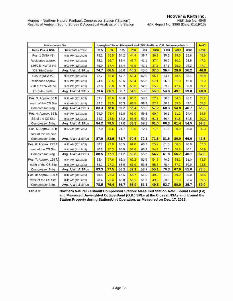
Measurement Set Unweighted Sound Pressure Level (SPL) in dB per O.B. Frequency (in Hz) A-Wt.Meas. Pos. & NSA Time/Date of Test 31.5 63 125 250 500 1000 2000 4000 8000 Level
Pos. 1 (NSA #1) 8:59 PM (12/17/15) 73.2 65.5 54.2 44.4 39.7 36.2 35.3 29.5 25.8 45.6Residence approx. 9:00 PM (12/17/15) 75.1 66.7 56.4 46.7 41.1 37.4 36.9 30.2 26.5 47.21,080 ft. NW of the 9:02 PM (12/17/15) 75.9 67.4 57.4 47.5 41.1 37.3 37.1 29.9 26.3 47.7
CS Site Center Avg. A-Wt. & SPLs 74.7 66.5 56.0 46.2 40.6 37.0 36.4 29.9 26.2 46.8Pos. 2 (NSA #2) 9:05 PM (12/17/15) 72.7 65.0 57.7 53.4 52.9 55.7 54.4 48.5 38.1 59.8
Residence approx. 9:07 PM (12/17/15) 74.4 66.5 59.5 56.4 55.3 57.1 56.6 51.3 42.0 61.9720 ft. SSW of the 9:08 PM (12/17/15) 73.8 66.8 58.9 53.6 52.5 55.2 53.5 47.4 36.8 59.2
CS Site Center Avg. A-Wt. & SPLs 73.6 66.1 58.7 54.5 53.6 56.0 54.8 49.1 39.0 60.3
Pos. 3: Approx. 50 ft. 8:31 AM (12/17/15) 83.4 78.6 66.0 65.2 58.3 57.2 60.3 54.5 46.2 65.2south of the CS Site 8:32 AM (12/17/15) 83.1 78.5 66.3 65.5 58.3 57.2 60.3 55.0 47.1 65.3Compressor Bldg. Avg. A-Wt. & SPLs 83.3 78.6 66.2 65.4 58.3 57.2 60.3 54.8 46.7 65.3
Pos. 4: Approx. 85 ft. 8:34 AM (12/17/15) 84.0 78.4 66.8 63.0 59.3 60.4 66.1 61.2 54.4 69.6SE of the CS Site 8:35 AM (12/17/15) 84.3 78.5 67.2 63.6 59.3 61.5 66.4 61.5 54.5 70.0Compressor Bldg. Avg. A-Wt. & SPLs 84.2 78.5 67.0 63.3 59.3 61.0 66.3 61.4 54.5 69.8
Pos. 5: Approx. 30 ft. 8:37 AM (12/17/15) 87.0 83.6 71.7 70.5 72.1 71.6 81.6 80.0 66.0 85.3east of the CS SiteCompressor Bldg. Avg. A-Wt. & SPLs 87.0 83.6 71.7 70.5 72.1 71.6 81.6 80.0 66.0 42.6
Pos. 6: Approx. 275 ft. 8:40 AM (12/17/15) 80.7 77.8 68.5 61.0 65.7 55.2 61.5 56.5 40.0 67.0east of the CS Site 8:41 AM (12/17/15) 80.2 76.3 65.9 58.6 65.3 54.2 62.0 56.8 40.1 66.9Compressor Bldg. Avg. A-Wt. & SPLs 80.5 77.1 67.2 59.8 65.5 54.7 61.8 56.7 40.1 67.0
Pos. 7: Approx. 195 ft. 8:44 AM (12/17/15) 83.4 77.6 66.3 62.2 53.9 54.8 70.2 68.1 51.0 73.5north of the CS Site 8:45 AM (12/17/15) 83.1 77.3 66.0 61.9 53.5 55.3 70.4 67.7 50.9 73.5Compressor Bldg. Avg. A-Wt. & SPLs 83.3 77.5 66.2 62.1 53.7 55.1 70.3 67.9 51.0 73.5
Pos. 8: Approx. 180 ft. 8:48 AM (12/17/15) 78.5 76.3 66.6 55.7 51.0 49.0 51.9 49.0 35.0 58.6west of the CS Site 8:49 AM (12/17/15) 78.4 76.4 66.8 56.1 51.1 49.9 53.5 51.0 36.4 59.5Compressor Bldg. Avg. A-Wt. & SPLs 78.5 76.4 66.7 55.9 51.1 49.5 52.7 50.0 35.7 59.0
Table 3: Northern Natural Faribault Compressor Station: Measured Station A-Wt. Sound Level (Ld)and Measured Unweighted Octave-Band (O.B.) SPLs at the Closest NSAs and around theStation Property during Station/Unit Operation, as Measured on Dec. 17, 2015.
Hoover & Keith Inc. Merjent – Northern Natural Faribault Compressor Station (“Station”) H&K Job No. 4846 Results of Ambient Sound Survey & Acoustical Analysis of the Station H&K Report No. 3390 (Date: 01/19/16)
-Page 18-
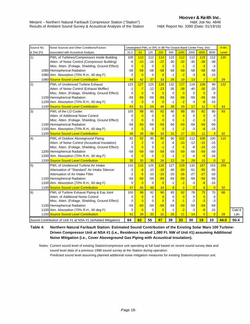
Source No. Noise Sources and Other Conditions/Factors Unweighted PWL or SPL in dB Per Octave-Band Center Freq. (Hz) A-Wt.& Dist (Ft) associated with Acoustical Analysis 31.5 63 125 250 500 1000 2000 4000 8000 Level
1) PWL of Turbines/Compressors inside Building 108 110 112 114 115 112 112 115 112 120Atten. of Noise Control (Compressor Building) -6 -10 -16 -22 -30 -32 -35 -38 -38Misc. Atten. (Foliage, Shielding, Ground Effect) 0 0 0 0 0 -1 -2 -3 -3
1080 Hemispherical Radiation -58 -58 -58 -58 -58 -58 -58 -58 -581080 Atm. Absorption (70% R.H., 60 deg F) 0 0 0 0 -1 -2 -3 -8 -151080 Source Sound Level Contribution 44 42 37 33 26 19 13 7 0 29
2) PWL of Unsilenced Turbine Exhaust 123 127 125 128 132 127 119 109 99 132Atten. of Noise Control (Exhaust Muffler) -1 -7 -12 -23 -35 -38 -40 -30 -20Misc. Atten. (Foliage, Shielding, Ground Effect) 0 0 0 0 0 0 0 0 0
1100 Hemispherical Radiation -59 -59 -59 -59 -59 -59 -59 -59 -591100 Atm. Absorption (70% R.H., 60 deg F) 0 0 0 0 -1 -2 -3 -8 -151100 Source Sound Level Contribution 63 61 54 46 38 29 17 12 5 43
3) PWL of the LO Cooler 105 98 95 92 90 88 85 82 80 93Atten. of Additional Noise Control 0 0 0 0 0 0 0 0 0Misc. Atten. (Foliage, Shielding, Ground Effect) 0 0 0 0 0 -1 -2 -3 -3
1100 Hemispherical Radiation -59 -59 -59 -59 -59 -59 -59 -59 -591100 Atm. Absorption (70% R.H., 60 deg F) 0 0 0 0 -1 -2 -3 -8 -151100 Source Sound Level Contribution 46 39 36 33 31 27 21 12 3 32
4) PWL of Outdoor Aboveground Piping 92 92 95 90 90 102 112 108 100 115Atten. of Noise Control (Acoustical Insulation) 2 2 0 -2 -6 -10 -12 -15 -15Misc. Atten. (Foliage, Shielding, Ground Effect) 0 0 0 -1 -2 -5 -8 -10 -10
1200 Hemispherical Radiation -59 -59 -59 -59 -59 -59 -59 -59 -591200 Atm. Absorption (70% R.H., 60 deg F) 0 0 0 -2 -1 -2 -4 -9 -161200 Source Sound Level Contribution 35 35 35 26 22 26 29 15 0 32
5) PWL of Unsilenced Turbine Air Intake 110 115 125 126 127 129 132 157 153 159Attenuation of "Standard" Air Intake Silencer -2 -6 -10 -18 -40 -50 -51 -55 -55Attenuation of Air Intake Filter -2 -5 -10 -15 -20 -26 -27 -27 -33
1100 Hemispherical Radiation -59 -59 -59 -59 -59 -59 -59 -59 -591100 Atm. Absorption (70% R.H., 60 deg F) 0 0 0 0 -1 -2 -3 -8 -151100 Source Sound Level Contribution 47 45 46 34 8 0 0 8 0 32
6) PWL of Turbine Exhaust Piping & Exp Joint 100 98 92 90 85 82 78 75 70 88Atten. of Additional Noise Control 0 0 0 0 0 0 0 0 0Misc. Atten. (Foliage, Shielding, Ground Effect) 0 0 0 0 0 -1 -2 -3 -3
1100 Hemispherical Radiation -59 -59 -59 -59 -59 -59 -59 -59 -591100 Atm. Absorption (70% R.H., 60 deg F) 0 0 0 0 -1 -2 -3 -8 -15 Calc'd1100 Source Sound Level Contribution 41 39 33 31 26 21 14 5 0 28 Ldn
Sound Contribution of Unit #1 at NSA #1 (w/Added Mitigation) 64 62 55 47 39 33 30 19 10 44.0 50.4
Table 4: Northern Natural Faribault Station: Estimated Sound Contribution of the Existing Solar Mars 100 Turbine-Driven Compressor Unit at NSA #1 (i.e., Residence located 1,080 Ft. NW of Unit #1) assuming AdditionalNoise Mitigation (i.e., Cover Aboveground Gas Piping with Acoustical Insulation).
Notes: Current sound level of existing Station/compressor unit operating at full load based on recent sound survey data andsound level data of a previous 1998 sound survey at the Station during operation.Predicted sound level assuming planned additional noise mitigation measures for existing Station/compressor unit.
Hoover & Keith Inc. Merjent – Northern Natural Faribault Compressor Station (“Station”) H&K Job No. 4846 Results of Ambient Sound Survey & Acoustical Analysis of the Station H&K Report No. 3390 (Date: 01/19/16)
-Page 19-
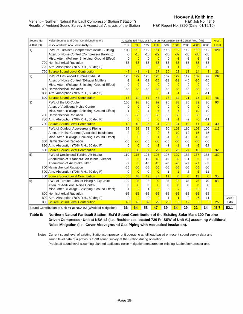
Source No. Noise Sources and Other Conditions/Factors Unweighted PWL or SPL in dB Per Octave-Band Center Freq. (Hz) A-Wt.& Dist (Ft) associated with Acoustical Analysis 31.5 63 125 250 500 1000 2000 4000 8000 Level
1) PWL of Turbines/Compressors inside Building 108 110 112 114 115 112 112 115 112 120Atten. of Noise Control (Compressor Building) -6 -10 -16 -22 -30 -32 -35 -38 -38Misc. Atten. (Foliage, Shielding, Ground Effect) 0 0 0 0 0 -1 -2 -3 -3
720 Hemispherical Radiation -55 -55 -55 -55 -55 -55 -55 -55 -55720 Atm. Absorption (70% R.H., 60 deg F) 0 0 0 0 -1 -1 -2 -5 -10720 Source Sound Level Contribution 47 45 41 37 30 23 18 14 6 33
2) PWL of Unsilenced Turbine Exhaust 123 127 125 128 132 127 119 109 99 132Atten. of Noise Control (Exhaust Muffler) -1 -7 -12 -26 -38 -38 -40 -30 -20Misc. Atten. (Foliage, Shielding, Ground Effect) 0 0 0 0 0 0 0 0 0
800 Hemispherical Radiation -56 -56 -56 -56 -56 -56 -56 -56 -56800 Atm. Absorption (70% R.H., 60 deg F) 0 0 0 0 -1 -1 -2 -6 -11800 Source Sound Level Contribution 66 64 57 46 38 32 21 17 12 45
3) PWL of the LO Cooler 105 98 95 92 90 88 85 82 80 93Atten. of Additional Noise Control 0 0 0 0 0 0 0 0 0Misc. Atten. (Foliage, Shielding, Ground Effect) -1 -2 -4 -5 -6 -7 -8 -10 -10
780 Hemispherical Radiation -56 -56 -56 -56 -56 -56 -56 -56 -56780 Atm. Absorption (70% R.H., 60 deg F) 0 0 0 0 -1 -1 -2 -6 -11780 Source Sound Level Contribution 48 40 35 31 28 24 19 11 4 30
4) PWL of Outdoor Aboveground Piping 92 92 95 90 90 102 110 106 100 113Atten. of Noise Control (Acoustical Insulation) 2 2 0 -2 -6 -10 -12 -15 -15Misc. Atten. (Foliage, Shielding, Ground Effect) 0 0 0 -1 -4 -9 -12 -12 -15
850 Hemispherical Radiation -56 -56 -56 -56 -56 -56 -56 -56 -56850 Atm. Absorption (70% R.H., 60 deg F) 0 0 0 -2 -1 -1 -3 -6 -12850 Source Sound Level Contribution 38 38 39 29 23 25 27 16 2 32
5) PWL of Unsilenced Turbine Air Intake 110 115 125 126 127 129 132 157 153 159Attenuation of "Standard" Air Intake Silencer -2 -6 -10 -18 -40 -50 -51 -55 -55Attenuation of Air Intake Filter -2 -5 -10 -15 -20 -26 -27 -27 -33
800 Hemispherical Radiation -56 -56 -56 -56 -56 -56 -56 -56 -56800 Atm. Absorption (70% R.H., 60 deg F) 0 0 0 0 -1 -1 -2 -6 -11800 Source Sound Level Contribution 50 48 49 37 11 0 0 13 0 35
6) PWL of Turbine Exhaust Piping & Exp Joint 100 98 92 90 85 82 78 75 70 88Atten. of Additional Noise Control 0 0 0 0 0 0 0 0 0Misc. Atten. (Foliage, Shielding, Ground Effect) -1 -2 -4 -5 -6 -7 -8 -10 -10
800 Hemispherical Radiation -56 -56 -56 -56 -56 -56 -56 -56 -56800 Atm. Absorption (70% R.H., 60 deg F) 0 0 0 0 -1 -1 -2 -6 -11 Calc'd800 Source Sound Level Contribution 43 40 32 29 23 18 12 3 0 25 Ldn
Sound Contribution of Unit #1 at NSA #2 (w/Added Mitigation) 66 64 58 47 39 34 29 22 14 45.7 52.1
Table 5: Northern Natural Faribault Station: Est'd Sound Contribution of the Existing Solar Mars 100 Turbine-Driven Compressor Unit at NSA #2 (i.e., Residences located 720 Ft. SSW of Unit #1) assuming AdditionalNoise Mitigation (i.e., Cover Aboveground Gas Piping with Acoustical Insulation).
Notes: Current sound level of existing Station/compressor unit operating at full load based on recent sound survey data andsound level data of a previous 1998 sound survey at the Station during operation.Predicted sound level assuming planned additional noise mitigation measures for existing Station/compressor unit.
Hoover & Keith Inc. Merjent – Northern Natural Faribault Compressor Station (“Station”) H&K Job No. 4846 Results of Ambient Sound Survey & Acoustical Analysis of the Station H&K Report No. 3390 (Date: 01/19/16)
-Page 20-
Source No. Noise Sources and Other Conditions/Factors Unweighted PWL or SPL in dB Per Octave-Band Center Freq. (Hz) A-Wt.& Dist (Ft) associated with Acoustical Analysis 31.5 63 125 250 500 1000 2000 4000 8000 Level
1) PWL of Turbines/Compressors inside Building 108 110 112 115 116 114 114 118 115 123Atten. of Noise Control (Compressor Building) -6 -10 -16 -22 -28 -32 -35 -38 -38Misc. Atten. (Foliage, Shielding, Ground Effect) 0 0 0 0 0 -1 -2 -3 -3
980 Hemispherical Radiation -58 -58 -58 -58 -58 -58 -58 -58 -58980 Atm. Absorption (70% R.H., 60 deg F) 0 0 0 0 -1 -1 -3 -7 -13980 Source Sound Level Contribution 44 42 38 35 30 22 17 12 3 31
2) PWL of Unsilenced Turbine Exhaust 123 127 125 128 132 127 119 109 99 132Atten. of Noise Control (Exhaust Muffler) -6 -16 -25 -35 -45 -45 -45 -35 -25Misc. Atten. (Foliage, Shielding, Ground Effect) 0 0 0 0 0 0 0 0 0
980 Hemispherical Radiation -58 -58 -58 -58 -58 -58 -58 -58 -58980 Atm. Absorption (70% R.H., 60 deg F) 0 0 0 0 -1 -1 -3 -7 -13980 Source Sound Level Contribution 59 53 42 35 29 23 14 9 3 33
3) PWL of the LO Cooler 105 98 95 92 90 88 85 82 80 93Atten. of Additional Noise Control 0 0 0 0 0 0 0 0 0Misc. Atten. (Foliage, Shielding, Ground Effect) 0 0 0 0 0 -1 -2 -3 -3
980 Hemispherical Radiation -58 -58 -58 -58 -58 -58 -58 -58 -58980 Atm. Absorption (70% R.H., 60 deg F) 0 0 0 0 -1 -1 -3 -7 -13980 Source Sound Level Contribution 47 40 37 34 32 28 23 14 6 33
4) PWL of Outdoor Aboveground Piping 95 95 98 92 92 95 110 105 100 113Atten. of Noise Control (Acoustical Insulation) 2 2 0 -2 -5 -12 -15 -16 -16Misc. Atten. (Foliage, Shielding, Ground Effect) 0 0 0 0 0 -1 -2 -3 -3
1050 Hemispherical Radiation -58 -58 -58 -58 -58 -58 -58 -58 -581050 Atm. Absorption (70% R.H., 60 deg F) 0 0 0 -2 -1 -2 -3 -8 -141050 Source Sound Level Contribution 39 39 40 30 28 22 32 20 8 35
5) PWL of Unsilenced Turbine Air Intake 110 115 125 126 127 129 132 157 153 159Attenuation of "Standard" Air Intake Silencer -2 -4 -7 -16 -40 -50 -51 -55 -55Attenuation of Air Intake Filter -2 -5 -10 -15 -20 -26 -27 -27 -33
980 Hemispherical Radiation -58 -58 -58 -58 -58 -58 -58 -58 -58980 Atm. Absorption (70% R.H., 60 deg F) 0 0 0 0 -1 -1 -3 -7 -13980 Source Sound Level Contribution 48 48 50 37 9 0 0 10 0 35
6) PWL of Turbine Exhaust Piping & Exp Joint 100 98 92 90 88 85 82 80 70 91Atten. of Additional Noise Control 0 0 0 0 0 0 0 0 0Misc. Atten. (Foliage, Shielding, Ground Effect) 0 0 0 0 0 -1 -2 -3 -3
980 Hemispherical Radiation -58 -58 -58 -58 -58 -58 -58 -58 -58980 Atm. Absorption (70% R.H., 60 deg F) 0 0 0 0 -1 -1 -3 -7 -13 Calc'd980 Source Sound Level Contribution 42 40 34 32 30 25 20 12 0 31 Ldn
Total Sound Contribution of Sources for new Unit at NSA #1 60 55 52 42 37 32 33 22 12 41.2 47.6
Sound Level (Ldn) of Existing Station/Unit at NSA: Note (1) 53.2Sound Level (Ldn) of Existing Station/Unit (w/Mitigation): Note (2) 50.4Sound Contribution of existing Unit (w/Mitigation) plus new Unit 52.2Potential Increase (+) or Decrease (-) in the Existing Level (dB) -1.0
Table 6: Northern Natural Faribault Station: Estimated Sound Contribution of new Solar Mars 100 Turbine-DrivenCompressor Unit at NSA #1 (i.e., Residence located 980 Ft. NW of the new Compressor Unit #2) alongwith the Estimated "Total" Station Sound Contribution (i.e., Operation of existing Station Unit plus thenew Mars 100 Compressor Unit). In addition, Estimated Increase in the Sound Level at NSA #1.
Note (1): Current sound level of existing Station/compressor unit operating at full load based on recent sound survey data.Note (2): Predicted sound level assuming planned additional noise mitigation measures for existing Station/compressor unit.
NOTE: Muffler DIL & Equipment PWL values on this spreadsheet should not be used as the specified values.Refer to "Noise Control Measures" section in report or other company specifications for actual specified values.
Hoover & Keith Inc. Merjent – Northern Natural Faribault Compressor Station (“Station”) H&K Job No. 4846 Results of Ambient Sound Survey & Acoustical Analysis of the Station H&K Report No. 3390 (Date: 01/19/16)
-Page 21-
Source No. Noise Sources and Other Conditions/Factors Unweighted PWL or SPL in dB Per Octave-Band Center Freq. (Hz) A-Wt.& Dist (Ft) associated with Acoustical Analysis 31.5 63 125 250 500 1000 2000 4000 8000 Level
1) PWL of Turbines/Compressors inside Building 108 110 112 115 116 114 114 118 115 123Atten. of Noise Control (Compressor Building) -6 -10 -16 -22 -28 -32 -35 -38 -38Misc. Atten. (Foliage, Shielding, Ground Effect) 0 0 -1 -2 -3 -4 -5 -6 -6
850 Hemispherical Radiation -56 -56 -56 -56 -56 -56 -56 -56 -56850 Atm. Absorption (70% R.H., 60 deg F) 0 0 0 0 -1 -1 -3 -6 -12850 Source Sound Level Contribution 46 44 39 34 28 20 15 11 3 30
2) PWL of Unsilenced Turbine Exhaust 123 127 125 128 132 127 119 109 99 132Atten. of Noise Control (Exhaust Muffler) -6 -16 -25 -35 -45 -45 -45 -35 -25Misc. Atten. (Foliage, Shielding, Ground Effect) 0 0 0 0 0 0 0 0 0
920 Hemispherical Radiation -57 -57 -57 -57 -57 -57 -57 -57 -57920 Atm. Absorption (70% R.H., 60 deg F) 0 0 0 0 -1 -1 -3 -7 -13920 Source Sound Level Contribution 60 54 43 36 29 24 14 10 4 34
3) PWL of the LO Cooler 105 98 95 92 90 88 85 82 80 93Atten. of Additional Noise Control 0 0 0 0 0 0 0 0 0Misc. Atten. (Foliage, Shielding, Ground Effect) 0 -1 -2 -4 -5 -6 -7 -8 -8
900 Hemispherical Radiation -57 -57 -57 -57 -57 -57 -57 -57 -57900 Atm. Absorption (70% R.H., 60 deg F) 0 0 0 0 -1 -1 -3 -7 -12900 Source Sound Level Contribution 48 40 36 31 28 24 19 10 3 30
4) PWL of Outdoor Aboveground Piping 95 95 98 92 92 95 110 105 100 113Atten. of Noise Control (Acoustical Insulation) 2 2 0 -2 -5 -12 -15 -16 -16Misc. Atten. (Foliage, Shielding, Ground Effect) 0 0 0 0 0 -1 -2 -3 -3
900 Hemispherical Radiation -57 -57 -57 -57 -57 -57 -57 -57 -57900 Atm. Absorption (70% R.H., 60 deg F) 0 0 0 -2 -1 -1 -3 -7 -12900 Source Sound Level Contribution 40 40 41 31 30 24 34 22 12 36
5) PWL of Unsilenced Turbine Air Intake 110 115 125 126 127 129 132 157 153 159Attenuation of "Standard" Air Intake Silencer -2 -4 -7 -16 -40 -50 -51 -55 -55Attenuation of Air Intake Filter -2 -5 -10 -15 -20 -26 -27 -27 -33
900 Hemispherical Radiation -57 -57 -57 -57 -57 -57 -57 -57 -57900 Atm. Absorption (70% R.H., 60 deg F) 0 0 0 0 -1 -1 -3 -7 -12900 Source Sound Level Contribution 49 49 51 38 10 0 0 11 0 36
6) PWL of Turbine Exhaust Piping & Exp Joint 100 98 92 90 88 85 82 80 70 91Atten. of Additional Noise Control 0 0 0 0 0 0 0 0 0Misc. Atten. (Foliage, Shielding, Ground Effect) 0 -1 -2 -4 -5 -6 -7 -8 -8
920 Hemispherical Radiation -57 -57 -57 -57 -57 -57 -57 -57 -57920 Atm. Absorption (70% R.H., 60 deg F) 0 0 0 0 -1 -1 -3 -7 -13 Calc'd920 Source Sound Level Contribution 43 40 33 29 25 21 15 8 0 27 Ldn
Total Sound Contribution of Sources for new Unit at NSA #2 61 56 52 42 35 30 34 24 14 41.3 47.7
Sound Level (Ldn) of Existing Station/Unit at NSA: Note (1) 53.8Sound Level (Ldn) of Existing Station/Unit (w/Mitigation): Note (2) 52.1Sound Contribution of existing Unit (w/Mitigation) plus new Unit 53.4Potential Increase (+) or Decrease (-) in the Existing Level (dB) -0.4
Table 7: Northern Natural Faribault Station: Estimated Sound Contribution of new Solar Mars 100 Turbine-DrivenCompressor Unit at NSA #2 (i.e., Residence located 850 Ft. SSW of the new Compressor Unit #2) alongwith the Estimated "Total" Station Sound Contribution (i.e., Operation of existing Station Unit plus thenew Mars 100 Compressor Unit). In addition, Estimated Increase in the Sound Level at NSA #2.
Note (1): Current sound level of existing Station/compressor unit operating at full load based on recent sound survey data.Note (2): Predicted sound level assuming planned additional noise mitigation measures for existing Station/compressor unit.
NOTE: Muffler DIL & Equipment PWL values on this spreadsheet should not be used as the specified values.Refer to "Noise Control Measures" section in report or other company specifications for actual specified values.
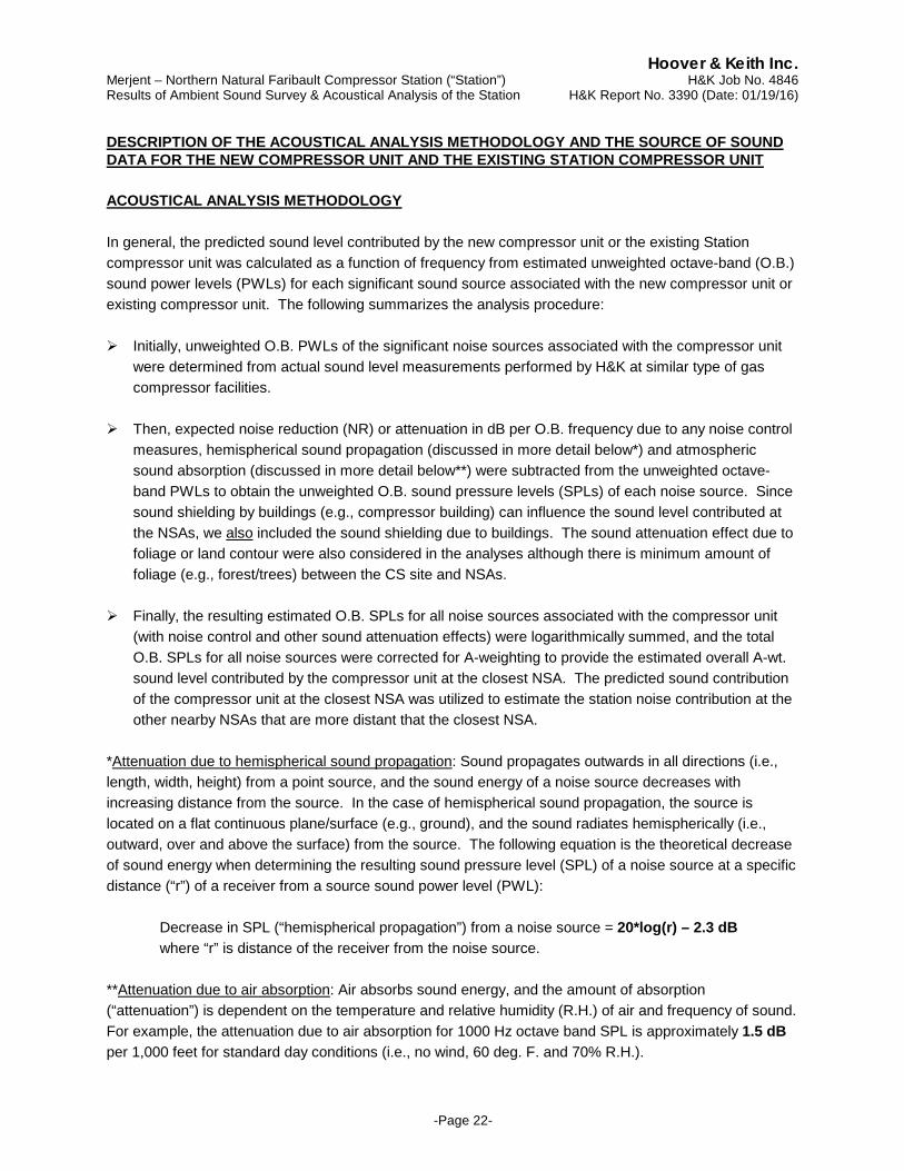
Hoover & Keith Inc. Merjent – Northern Natural Faribault Compressor Station (“Station”) H&K Job No. 4846 Results of Ambient Sound Survey & Acoustical Analysis of the Station H&K Report No. 3390 (Date: 01/19/16)
-Page 22-
DESCRIPTION OF THE ACOUSTICAL ANALYSIS METHODOLOGY AND THE SOURCE OF SOUND DATA FOR THE NEW COMPRESSOR UNIT AND THE EXISTING STATION COMPRESSOR UNIT ACOUSTICAL ANALYSIS METHODOLOGY In general, the predicted sound level contributed by the new compressor unit or the existing Station compressor unit was calculated as a function of frequency from estimated unweighted octave-band (O.B.) sound power levels (PWLs) for each significant sound source associated with the new compressor unit or existing compressor unit. The following summarizes the analysis procedure: Initially, unweighted O.B. PWLs of the significant noise sources associated with the compressor unit
were determined from actual sound level measurements performed by H&K at similar type of gas compressor facilities.
Then, expected noise reduction (NR) or attenuation in dB per O.B. frequency due to any noise control measures, hemispherical sound propagation (discussed in more detail below*) and atmospheric sound absorption (discussed in more detail below**) were subtracted from the unweighted octave-band PWLs to obtain the unweighted O.B. sound pressure levels (SPLs) of each noise source. Since sound shielding by buildings (e.g., compressor building) can influence the sound level contributed at the NSAs, we also included the sound shielding due to buildings. The sound attenuation effect due to foliage or land contour were also considered in the analyses although there is minimum amount of foliage (e.g., forest/trees) between the CS site and NSAs.
Finally, the resulting estimated O.B. SPLs for all noise sources associated with the compressor unit
(with noise control and other sound attenuation effects) were logarithmically summed, and the total O.B. SPLs for all noise sources were corrected for A-weighting to provide the estimated overall A-wt. sound level contributed by the compressor unit at the closest NSA. The predicted sound contribution of the compressor unit at the closest NSA was utilized to estimate the station noise contribution at the other nearby NSAs that are more distant that the closest NSA.
*Attenuation due to hemispherical sound propagation: Sound propagates outwards in all directions (i.e., length, width, height) from a point source, and the sound energy of a noise source decreases with increasing distance from the source. In the case of hemispherical sound propagation, the source is located on a flat continuous plane/surface (e.g., ground), and the sound radiates hemispherically (i.e., outward, over and above the surface) from the source. The following equation is the theoretical decrease of sound energy when determining the resulting sound pressure level (SPL) of a noise source at a specific distance (“r”) of a receiver from a source sound power level (PWL):
Decrease in SPL (“hemispherical propagation”) from a noise source = 20*log(r) – 2.3 dB where “r” is distance of the receiver from the noise source.
**Attenuation due to air absorption: Air absorbs sound energy, and the amount of absorption (“attenuation”) is dependent on the temperature and relative humidity (R.H.) of air and frequency of sound. For example, the attenuation due to air absorption for 1000 Hz octave band SPL is approximately 1.5 dB per 1,000 feet for standard day conditions (i.e., no wind, 60 deg. F. and 70% R.H.).
Hoover & Keith Inc. Merjent – Northern Natural Faribault Compressor Station (“Station”) H&K Job No. 4846 Results of Ambient Sound Survey & Acoustical Analysis of the Station H&K Report No. 3390 (Date: 01/19/16)
-Page 23-
ANALYSIS & METHODOLOGY (NOISE ATTRIBUTABLE TO A BLOWDOWN EVENT) The noise resulting from a blowdown event was estimated by using the “inverse-square law” and included some attenuation due to atmospheric sound absorption. Consequently, the estimated noise of a blowdown event at the receptor (i.e., closest NSA) was calculated as follows:
SPL (receptor) = (Blowdown SPL at R1) – 20*log(R2/R1) – Atm. Atten. = 60 dBA – 20*log(1000/300) – 3 dB = 46 dBA Where: R1 = Distance of Specified Blowdown Noise Level Requirement (i.e., 300 ft.)
R2 = Distance of the Closest Receptor from the Blowdown Silencer (1,000 ft.) SOURCE OF SOUND DATA The following describes the source of sound data for estimating the source sound levels and source PWLs used in the acoustical analysis. Note that equipment noise levels utilized in the acoustical analysis are generally higher than the sound level requirement for equipment to insure that the design incorporates an acoustical “margin of safety.” (1) Estimated PWL values of the specific equipment inside the building (i.e., noise of the turbine and
compressor) was calculated from sound data measured by H&K on a very similar type of gas compressor installation;
(2) Turbine exhaust PWL values for the Solar turbine were calculated from sound data provided by
Solar (i.e., sound data in the Solar Noise Prediction Guidelines Document) and/or estimated sound level data measured by H&K on a similar turbine installations;
(3) Noise radiated from aboveground gas piping is primarily a result the noise generated by the gas
compressor. Consequently, measurement of both near field and far field sound data on gas piping is presumed to be an accurate method of quantifying the noise associated with piping, and estimated PWL values for piping used in the analysis were determined from near field and far field sound data by H&K on a similar type of compressor to that of the new compressor unit;
(4) PWL values for the lube-oil cooler (“LO cooler”) were designated to meet the design noise goal.
Note that the estimated PWL for the cooler utilized in the acoustical analysis assumes some noise associated with piping associated with the coolers. The noise level for the LO cooler used in the acoustical analysis is generally higher than the sound level requirement in order that the noise design analysis incorporates an acoustical “margin of safety.” In addition, there can be other noise associated with the cooler that is not directly related to the operation of the cooler fans;
(5) Estimated PWL values for the turbine air intake were calculated from sound data provided by
Solar (i.e., sound data in the Solar Noise Prediction Guidelines Document), although low-frequency O.B. SPLs were modified based on field tests by H&K. The estimated A-wt. sound level of a unit blowdown event, assuming that the blowdown vent includes a silencer that meets the specified noise level, was based on field test by H&K.
File: \Merjent\Northern Lights 2017 Project\H&K Reports\Faribault Station\H&K Report – NNG Faribault Station – Acoustical Analysis of Compressor Addition.doc
End of Report