jamaica broilers ethanol dehydration plant wastewater … · 2015-07-10 · jamaica broilers...
TRANSCRIPT
Jamaica Broilers Ethanol Dehydration Plant Wastewater Treatment Facility Port Esquivel, St. Catherine, Jamaica
Waste Treatment and Disposal Options Preliminary Analysis
and Discussion of Effluent Water Quality Standard
Requirement by NEPA/NRCA
Prepared by FLUID SYSTEMS ENGINEERING LIMITED
OCTOBER 2006

Jamaica Broilers Ethanol Dehydration Plant Wastewater Treatment Facility
Waste Treatment and Disposal Options
Preliminary Analysis and
Discussion of Effluent Water Quality Standard Requirement by NEPA/NRCA
TABLE OF CONTENTS 1. INTRODUCTION ................................................................................................................................ 1
2. DATA PROVIDED BY JAMAICA BROILERS ............................................................................... 2
3. SUMMARY OF WASTE STREAM DATA PROVIDED AND ESTIMATED ............................... 5
4. SEWAGE ORGANIC AND NUTRIENT LOAD ESTIMATE ......................................................... 6 4.1. DISCUSSION OF REGULATORY FRAMEWORK ................................................................................... 6
5. SEWAGE TREATMENT OPTIONS .................................................................................................. 8 5.1. TREATMENT OPTION MATRIX ......................................................................................................... 9
6. TREATMENT SYSTEM RECOMMENDATIONS...........................................................................10
7. STABILIZATION POND TREATMENT AND ITS VARIANTS .................................................11
8. DESIGN OF RECOMMENDED TREATMENT FACILITY ..........................................................11 8.1. SEPTIC TANK / ANAEROBIC POND OPTION - DESCRIPTION AND SYSTEM CAPACITY .......................11 8.2. SEPTIC TANK - MITIGATION OF OPERATIONAL RISKS......................................................................12 8.3. STABILIZATION PONDS - DESCRIPTION AND SYSTEM CAPACITY .....................................................13 8.4. STABILIZATION PONDS - OPERATIONAL RISKS AND MITIGATION ...................................................16
9. LOCATION OF PROPOSED SEWAGE TREATMENT PONDS .................................................17
TABLE OF FIGURES
FIGURE 1: TOPOGRAPHIC MAP OF SITE WITH PLANIMETRIC FEATURES ............................................ 3 FIGURE 2: OBLIQUE AERIAL PHOTO OF SITE WITH TOTAL PROJECT AREA DELINEATED IN RED ............ 3 FIGURE 3: SOILS WITHIN THE PROPOSED DEVELOPMENT SITE AND GENERAL VICINITY ....................... 4 FIGURE 4: AERIAL VIEW OF SITE AND COASTAL LAGOON AREA ......................................................... 4 FIGURE 5: SEPTIC TANK TYPICAL DETAIL ..................................................................................... 12 FIGURE 6: GENERAL ARRANGEMENT OF THE TREATMENT PONDS .................................................. 13 FIGURE 7: LOCATION OF WASTE WATER TREATMENT PLANT RELATIVE TO DEHYDRATION PLANT ...... 17
TABLE OF TABLES TABLE 1: SUMMARY OF WASTE STREAM DATA ................................................................................. 5 TABLE 2: COMPOSITE WASTE STREAM PROJECTION ......................................................................... 6 TABLE 3: UNTREATED WASTE STREAM CHARACTERISTICS .............................................................. 6 TABLE 4: NEPA TRADE EFFLUENT REQUIREMENT .......................................................................... 7 TABLE 4: TREATMENT OPTIONS MATRIX ......................................................................................... 9 TABLE 5: PONDS DESIGN - SHEET 1 ............................................................................................ 14 TABLE 6: PONDS DESIGN - SHEET 2 ............................................................................................ 15 TABLE 7: PONDS DESIGN - SHEET 3 ............................................................................................ 16

1. Introduction
The Jamaica Broilers Group, Jamaica’s pioneer commercial producer of broiler meat, has a fully integrated poultry operation and has also diversified into feed milling, cattle rearing, beef production and fish farming, along with the development and marketing of other value-added products for both local consumption and export.
The Jamaica Broilers Group has also devoted significant resources to developing affiliated services that support the varied agricultural operations. These include veterinary and nutritional services, the wholesale and retail of a full range of farm products and the premixing of feed ingredients and concentrate.
The Jamaica Broilers Group recently announced that it would be investing U$14,000,000 to establish an ethanol dehydration plant capable of producing 60 million gallons per year of fuel grade ethanol.
Fluid Systems Engineering Limited, Consulting Engineers was requested to determine the sewage treatment requirement for the waste stream that is expected from this facility. This determination in the first instance is to form the basis of a submission to the National Environmental and Planning Authority NEPA (Jamaica) for a construction permit of the proposed wastewater treatment plant and a license to discharge trade effluent.
Limited information was provided as to the projected quantity and nature of the waste streams for the various components for the dehydration plant. It will therefore only be possible at this stage to prepare outline designs of the treatment options for the expected composite waste stream so that a preferred treatment approach can be selected. With the selection of the preferred approach, a preliminary design and plant layout will be required for submission to the regulatory agency.
JB Ethanol Dehydration Plant, Wastewater Treatment, Disposal Options – October 2006 Fluid Systems Engineering Ltd
Page 1

2. Data provided by Jamaica Broilers The following data was provided by the Client. The information is limited and clearly there are implications relating to the operation of the dehydration plant and the source and nature of the hydrous feed stock that will ultimately influence the final waste treatment requirements. Dehydration Plant 4,000 liters per hour (contains MAX 0.03% alcohol by volume) {Assume 24/7 Operations} Typical characteristics are below.
Sr. No. Analytical Parameter Unit Value
1 Ethanol Content ppm 500 max. 2 Appearance Colourless 3 BOD ppm 150 – 200 4 COD ppm 300 – 400 5 Other Chemicals ppm Nil 6 pH 4 - 5
Boiler Typical blow-down from 40,000 PPH boiler. Will contain Calcium Carbonates and Sulphates. {Assume 24/7 Operations} Cooling Tower Similar characteristics as Boiler – volumes at MAXIMUM of 5,000 liters per hour. {Assume 24/7 Operations} Human Wastes Budget for 50 persons maximum.
The engineers for the dehydration plant provided a preliminary P and ID chart which is attached separately as a PDF file.
JB Ethanol Dehydration Plant, Wastewater Treatment, Disposal Options – October 2006 Fluid Systems Engineering Ltd
Page 2
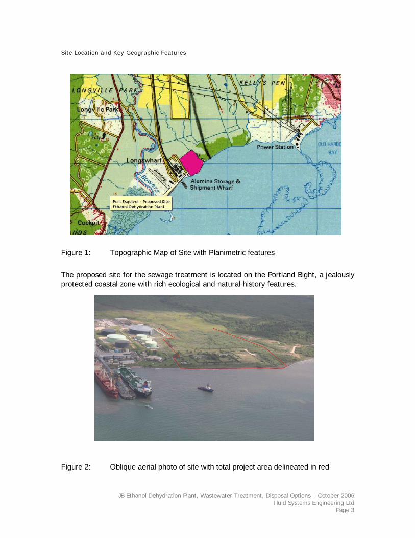
Site Location and Key Geographic Features
Figure 1: Topographic Map of Site with Planimetric features
The proposed site for the sewage treatment is located on the Portland Bight, a jealously protected coastal zone with rich ecological and natural history features.
Figure 2: Oblique aerial photo of site with total project area delineated in red
JB Ethanol Dehydration Plant, Wastewater Treatment, Disposal Options – October 2006 Fluid Systems Engineering Ltd
Page 3
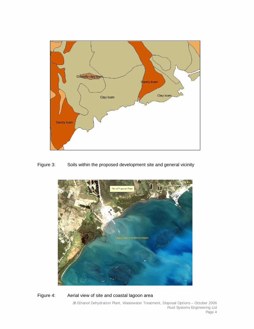
Figure 3: Soils within the proposed development site and general vicinity
Figure 4: Aerial view of site and coastal lagoon area JB Ethanol Dehydration Plant, Wastewater Treatment, Disposal Options – October 2006
Fluid Systems Engineering Ltd Page 4
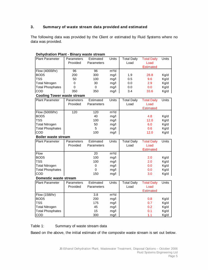
3. Summary of waste stream data provided and estimated The following data was provided by the Client or estimated by Fluid Systems where no data was provided.
Table 1: Summary of waste stream data
Based on the above, the initial estimate of the composite waste stream is set out below.
Dehydration Plant - Binary waste streamPlant Parameter Parameters
ProvidedEstimated
ParametersUnits Total Daily
LoadTotal Daily
Load Estimated
Units
Flow (4000l/hr) 96 96 m³/dBOD5 200 300 mg/l 1.9 28.8 Kg/dTSS 50 100 mg/l 0.5 9.6 Kg/dTotal Nitrogen 0 30 mg/l 0.0 2.9 Kg/dTotal Phosphates 0 0 mg/l 0.0 0.0 Kg/dCOD 350 350 mg/l 3.4 33.6 Kg/dCooling Tower waste streamPlant Parameter Parameters
ProvidedEstimated
ParametersUnits Total Daily
LoadTotal Daily
Load Estimated
Units
Flow (5000l/hr) 120 120 m³/dBOD5 40 mg/l 4.8 Kg/dTSS 100 mg/l 12.0 Kg/dTotal Nitrogen 50 mg/l 6.0 Kg/dTotal Phosphates 5 mg/l 0.6 Kg/dCOD 100 mg/l 12.0 Kg/dBoiler waste streamPlant Parameter Parameters
ProvidedEstimated
ParametersUnits Total Daily
LoadTotal Daily
Load Estimated
Units
Flow 20 m³/dBOD5 100 mg/l 2.0 Kg/dTSS 100 mg/l 2.0 Kg/dTotal Nitrogen 0 mg/l 0.0 Kg/dTotal Phosphates 0 mg/l 0.0 Kg/dCOD 150 mg/l 3.0 Kg/dDomestic waste streamPlant Parameter Parameters
ProvidedEstimated
ParametersUnits Total Daily
LoadTotal Daily
Load Estimated
Units
Flow (158l/hr) 3.8 m³/dBOD5 200 mg/l 0.8 Kg/dTSS 175 mg/l 0.7 Kg/dTotal Nitrogen 45 mg/l 0.2 Kg/dTotal Phosphates 15 mg/l 0.1 Kg/dCOD 300 mg/l 1.1 Kg/d
JB Ethanol Dehydration Plant, Wastewater Treatment, Disposal Options – October 2006 Fluid Systems Engineering Ltd
Page 5
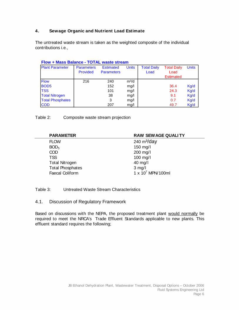
4. Sewage Organic and Nutrient Load Estimate The untreated waste stream is taken as the weighted composite of the individual contributions i.e.,
Table 2: Composite waste stream projection
PARAMETER RAW SEWAGE QUALITY FLOW 240 m³/day
BOD5 150 mg/l COD 200 mg/l TSS 100 mg/l Total Nitrogen 40 mg/l Total Phosphates 3 mg/l Faecal Coliform 1 x 10⁷ MPN/100ml
Table 3: Untreated Waste Stream Characteristics
4.1. Discussion of Regulatory Framework Based on discussions with the NEPA, the proposed treatment plant would normally be required to meet the NRCA’s Trade Effluent Standards applicable to new plants. This effluent standard requires the following;
Flow + Mass Balance - TOTAL waste streamPlant Parameter Parameters
ProvidedEstimated
ParametersUnits Total Daily
LoadTotal Daily
Load Estimated
Units
Flow 216 240 m³/dBOD5 152 mg/l 36.4 Kg/dTSS 101 mg/l 24.3 Kg/dTotal Nitrogen 38 mg/l 9.1 Kg/dTotal Phosphates 3 mg/l 0.7 Kg/dCOD 207 mg/l 49.7 Kg/d
JB Ethanol Dehydration Plant, Wastewater Treatment, Disposal Options – October 2006 Fluid Systems Engineering Ltd
Page 6
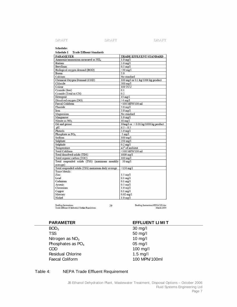
PARAMETER EFFLUENT LIMIT BOD5 30 mg/l TSS 50 mg/l Nitrogen as NO3 10 mg/l Phosphates as PO4 05 mg/l COD 100 mg/l Residual Chlorine 1.5 mg/l Faecal Coliform 100 MPN/100ml
Table 4: NEPA Trade Effluent Requirement
JB Ethanol Dehydration Plant, Wastewater Treatment, Disposal Options – October 2006 Fluid Systems Engineering Ltd
Page 7
Based on the above schedules, it will be necessary to remove substantial components of the carbonaceous and nitrogen based pollutants in the raw waste stream. Disinfection will be necessary for the effluent from the plant to meet the set bacteriological standards.
5. Sewage Treatment Options Generally, the sewage treatment options considered can be classified into four main groups based on the secondary treatment process utilized. For tertiary treatment, common options will be shared. The main groups are; Suspended Growth Systems: Activated Sludge Aeration options: Diffused Air, Surface Aeration, Hybrid Mixing options: Propeller mixers BNR: Various proprietary configurations CNR: Precipitation of phosphates with alum Disinfection: Chlorine, UV Sludge Treatment: Aerobic Stabilization, dewatering drying beds.
Activated Sludge (Ditch Systems) Aeration options: Surface Aeration, Hybrid Mixing options: Propeller mixers BNR: Various proprietary configurations CNR: Precipitation of phosphates with alum Disinfection: Chlorine, UV Sludge Treatment: Aerobic Stabilization, dewatering drying beds. Fixed Growth Systems: Rotating Biological Contactors Aeration options: Proprietary entrainment Mixing options: BNR: Nitrogen capable only in extended configuration CNR: Precipitation of phosphates with alum Disinfection: Chlorine, UV Sludge Treatment: Aerobic Stabilization, dewatering drying beds. Hybrid Systems (Fixed and Suspended): STM-Aerotor™ process. Aeration options: Proprietary entrainment Mixing options: Proprietary BNR: Nitrogen capable, limited Phosphorus CNR: Precipitation of phosphates with alum Disinfection: Chlorine, UV Sludge Treatment: Aerobic Stabilization, dewatering drying beds.
JB Ethanol Dehydration Plant, Wastewater Treatment, Disposal Options – October 2006 Fluid Systems Engineering Ltd
Page 8
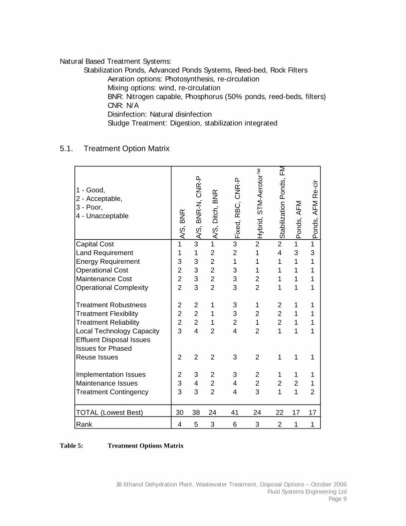
Natural Based Treatment Systems: Stabilization Ponds, Advanced Ponds Systems, Reed-bed, Rock Filters Aeration options: Photosynthesis, re-circulation Mixing options: wind, re-circulation BNR: Nitrogen capable, Phosphorus (50% ponds, reed-beds, filters) CNR: N/A Disinfection: Natural disinfection Sludge Treatment: Digestion, stabilization integrated
5.1. Treatment Option Matrix
Table 5: Treatment Options Matrix
1 - Good, 2 - Acceptable, 3 - Poor, 4 - Unacceptable
A/S,
BN
R
A/S,
BN
R-N
, CN
R-P
A/S,
Ditc
h, B
NR
Fixe
d, R
BC, C
NR
-P
Hyb
rid, S
TM-A
erot
or™
Stab
ilizat
ion
Pond
s, F
M
Pond
s, A
FM
Pond
s, A
FM R
e-ci
r
Capital Cost 1 3 1 3 2 2 1 1Land Requirement 1 1 2 2 1 4 3 3Energy Requirement 3 3 2 1 1 1 1 1Operational Cost 2 3 2 3 1 1 1 1Maintenance Cost 2 3 2 3 2 1 1 1Operational Complexity 2 3 2 3 2 1 1 1
Treatment Robustness 2 2 1 3 1 2 1 1Treatment Flexibility 2 2 1 3 2 2 1 1Treatment Reliability 2 2 1 2 1 2 1 1Local Technology Capacity 3 4 2 4 2 1 1 1Effluent Disposal IssuesIssues for Phased Reuse Issues 2 2 2 3 2 1 1 1
Implementation Issues 2 3 2 3 2 1 1 1Maintenance Issues 3 4 2 4 2 2 2 1Treatment Contingency 3 3 2 4 3 1 1 2
TOTAL (Lowest Best) 30 38 24 41 24 22 17 17
Rank 4 5 3 6 3 2 1 1
JB Ethanol Dehydration Plant, Wastewater Treatment, Disposal Options – October 2006 Fluid Systems Engineering Ltd
Page 9
A preliminary analysis of sewage treatment options, considered appropriate for the proposed development suggest that sewage treatment methodologies utilizing low energy input and simple technology for process operation and maintenance should be given the greatest consideration. Sewage stabilization ponds, configured with anaerobic, facultative, maturation units and recirculation arrangements, presented a robust treatment option. The large land space requirement for the ponds and for the necessary setback in many situations, exclude these solutions. High rate sewage treatment options based on the activated sludge process, where nutrient removal is available, generally leads to the use of the oxidation ditch process in Jamaica. It provides the best option when energy use and simplicity of operations is considered. The BNR configurations of these systems require increased complexity not appropriate for relatively small sewage flows. Several proprietary and hybrid high rate suspended and fixed growth treatment systems are available in the marketplace. Systems with any feature graded un-acceptable will not be considered.
6. Treatment System Recommendations Based on the outcome of the treatment matrix analysis and the general discussion, the following options for sewage treatment for the proposed Jamaica Broilers Ethanol Processing Plant have been reviewed.
1. Stabilization Ponds lined (AFM), if a suitable site adjacent to the development area can be found. Land area required 0.3 ha.
2. Recirculation enhanced stabilization pond system (AFM³r) with appropriate lining,
if a suitable site adjacent to the development area can be found. Land area required 0.22 ha.
JB Ethanol Dehydration Plant, Wastewater Treatment, Disposal Options – October 2006 Fluid Systems Engineering Ltd
Page 10

7. Stabilization Pond Treatment and its variants Generally for the treatment requirements necessary, a stabilization pond system is highly recommended. Stabilization ponds wastewater treatment systems have several different configurations.
• The most basic is the use of facultative ponds and maturation ponds (FM³). This configuration also has the highest demand for land.
• By incorporating an anaerobic pond as a pre-treatment system, the land area of
the basic system can be reduced by about 15% (AFM³). Odours associated with poorly designed anaerobic ponds have given them a bad ‘rap’ and their use has been generally avoided. Improved design technology has addressed the issues and these systems are now gaining significant acceptance.
• The robust nature of the ponds systems and their wide acceptance has in recent
times led to the development of more advanced applications. The (AFM³r) recirculation enhanced pond system is a variant that includes the provision for re-circulation, allowing a high rate of loading of the main treatment pond. This reduces land area requirement but more importantly, gives much needed operational flexibility especially for small systems.
Pond systems are highly integrated biological, physical and chemical ecologic balances. They can get upset and during such times (change of climate, long overcast periods etc.) they do need some help. The (AFM³r) recirculation enhanced pond system is best suited to address such situations.
8. Design of Recommended Treatment Facility
8.1. Septic Tank / Anaerobic Pond Option - Description and System capacity The anaerobic section of the treatment plant will be provided either with the use of a 0.75 day retention septic tank or covered anaerobic lagoon. In the case of a covered lagoon, a de-sludge facility will be provided. The anaerobic section of the plant will allow for the removal of suspended solids and some homogenizing of the waste stream. The sludge load will also be reduced by digestion. The basic dimensions of the septic tank will be 3m deep x 15m long x 4 m wide. For the covered anaerobic tank option, the basic dimensions will be 2.5m deep x 16m long x 4.5 m wide adjusted to maintain the prescribed volume within provision of the side slopes.
JB Ethanol Dehydration Plant, Wastewater Treatment, Disposal Options – October 2006 Fluid Systems Engineering Ltd
Page 11
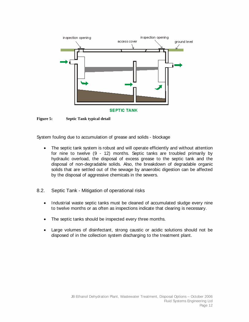
Figure 5: Septic Tank typical detail
System fouling due to accumulation of grease and solids - blockage
• The septic tank system is robust and will operate efficiently and without attention for nine to twelve (9 - 12) months. Septic tanks are troubled primarily by hydraulic overload, the disposal of excess grease to the septic tank and the disposal of non-degradable solids. Also, the breakdown of degradable organic solids that are settled out of the sewage by anaerobic digestion can be affected by the disposal of aggressive chemicals in the sewers.
8.2. Septic Tank - Mitigation of operational risks
• Industrial waste septic tanks must be cleaned of accumulated sludge every nine to twelve months or as often as inspections indicate that clearing is necessary.
• The septic tanks should be inspected every three months.
• Large volumes of disinfectant, strong caustic or acidic solutions should not be
disposed of in the collection system discharging to the treatment plant.
JB Ethanol Dehydration Plant, Wastewater Treatment, Disposal Options – October 2006 Fluid Systems Engineering Ltd
Page 12
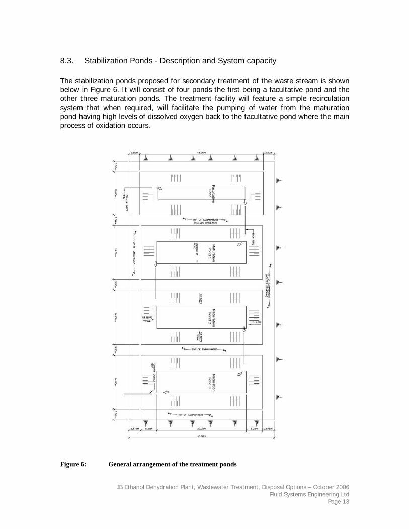
8.3. Stabilization Ponds - Description and System capacity The stabilization ponds proposed for secondary treatment of the waste stream is shown below in Figure 6. It will consist of four ponds the first being a facultative pond and the other three maturation ponds. The treatment facility will feature a simple recirculation system that when required, will facilitate the pumping of water from the maturation pond having high levels of dissolved oxygen back to the facultative pond where the main process of oxidation occurs.
Figure 6: General arrangement of the treatment ponds
JB Ethanol Dehydration Plant, Wastewater Treatment, Disposal Options – October 2006
Fluid Systems Engineering Ltd Page 13
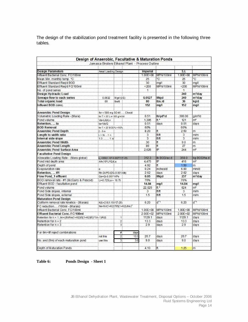
The design of the stabilization pond treatment facility is presented in the following three tables.
Table 6: Ponds Design - Sheet 1
JB Ethanol Dehydration Plant, Wastewater Treatment, Disposal Options – October 2006 Fluid Systems Engineering Ltd
Page 14

Table 7: Ponds Design - Sheet 2
JB Ethanol Dehydration Plant, Wastewater Treatment, Disposal Options – October 2006 Fluid Systems Engineering Ltd
Page 15
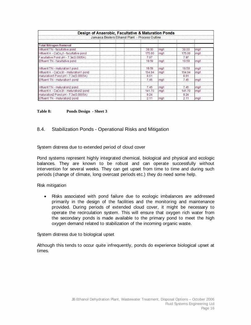
Table 8: Ponds Design - Sheet 3
8.4. Stabilization Ponds - Operational Risks and Mitigation System distress due to extended period of cloud cover Pond systems represent highly integrated chemical, biological and physical and ecologic balances. They are known to be robust and can operate successfully without intervention for several weeks. They can get upset from time to time and during such periods (change of climate, long overcast periods etc.) they do need some help. Risk mitigation
• Risks associated with pond failure due to ecologic imbalances are addressed primarily in the design of the facilities and the monitoring and maintenance provided. During periods of extended cloud cover, it might be necessary to operate the recirculation system. This will ensure that oxygen rich water from the secondary ponds is made available to the primary pond to meet the high oxygen demand related to stabilization of the incoming organic waste.
System distress due to biological upset Although this tends to occur quite infrequently, ponds do experience biological upset at times.
JB Ethanol Dehydration Plant, Wastewater Treatment, Disposal Options – October 2006 Fluid Systems Engineering Ltd
Page 16
Risk mitigation
• The recirculation of water from the secondary ponds will re-establish the required biological balance within a period of a day or two and return the system to stability. Odors if they occur at all, will be detectable in the immediate vicinity of the ponds during such period but it must be stressed that such situation are not expected more frequently that once or less per year.
Damage to pond structure due to hurricane storm surge or run-up wave During the passage of hurricane, high sea water levels associated with storm surge and wave run-up can damage coastal structures. Risk mitigation
• This risk is addressed primarily in the locating and design of the ponds. The pond embankments will be protected from wave action with the use of a geo-textile cover and stone armour.
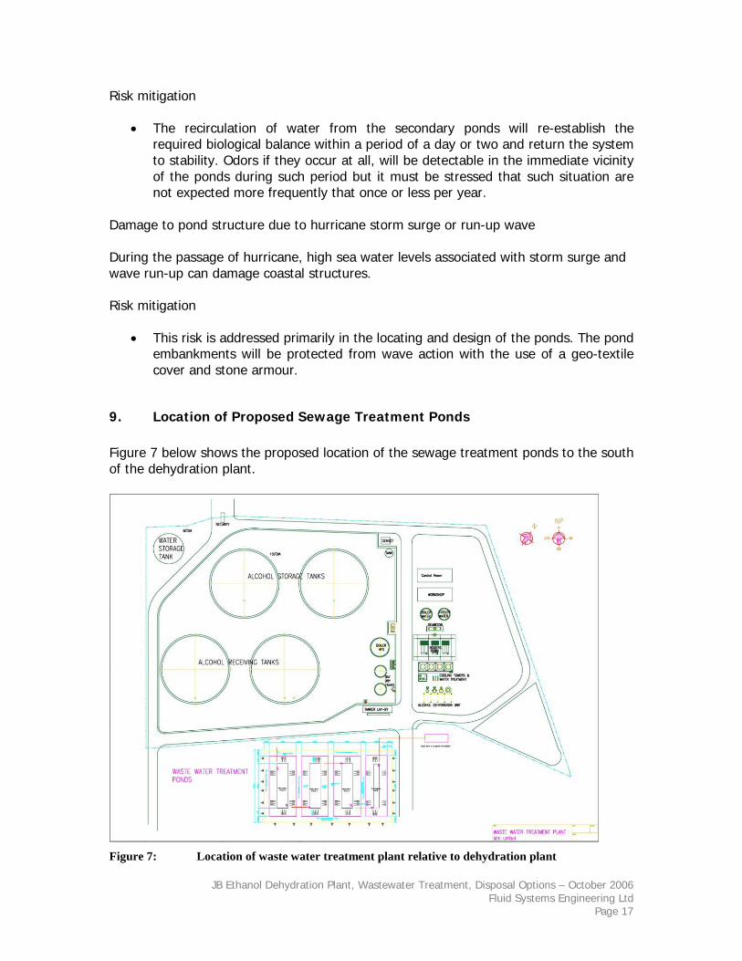
9. Location of Proposed Sewage Treatment Ponds Figure 7 below shows the proposed location of the sewage treatment ponds to the south of the dehydration plant.
Figure 7: Location of waste water treatment plant relative to dehydration plant
JB Ethanol Dehydration Plant, Wastewater Treatment, Disposal Options – October 2006 Fluid Systems Engineering Ltd
Page 17