j. m. doyle, j.m. and fang, s.j. underground pipe ...freeit.free.fr/structure engineering...
TRANSCRIPT

J. M. Doyle, J.M. and Fang, S.J. “Underground Pipe”Structural Engineering HandbookEd. Chen Wai-FahBoca Raton: CRC Press LLC, 1999
Underground Pipe
J. M. Doyle andS.J. FangSargent & Lundy, LLCChicago, IL
25.1 Introduction25.2 External Loads
Overburden • Surcharge at Grade • Live Loads • Seismic Loads
25.3 Internal LoadsInternal Pressure and Vacuum • Pipe and Contents
25.4 Design MethodsGeneral • Flexible Design • Rigid Design
25.5 JointsGeneral • Joint Types • Hydrostatic Testing
25.6 Corrosion ProtectionCoatings • Cathodic Protection
References
25.1 Introduction
Throughout recorded history, works have been constructed for conveying water from one place toanother. The Roman aqueducts are often mentioned as examples of great technical achievement;indeed, some of these early structures are still in use today. Although most of the early water carryingstructures were open channels, conduits and pipes of various materials were also used in Romantimes. It appears, though, that the effectiveness of the early pipes was limited because their materialswere weak in tensile capacity. Therefore, the pipes could not carry fluid under any appreciablepressure. Beginning in the 17th century, wood and cast iron were used in water pipe applicationsin order to carry water under pressure from pumping, which was introduced about the same time.Since then, many materials have evolved for use in pipes. As a general rule, the goals for new pipematerial development has been increased tensile strength, reduced weight, and, of course, reducedcost.
Pipe that is buried underground must sustain other loads besides the internal fluid pressure. Thatis, it must support the soil overburden, groundwater, loads applied at the ground surface, such asvehicular traffic, and forces induced by seismic motion. Buried pipe is, therefore, a structure aswell as a conduit for conveying fluid. That being the case, special design procedures are required toinsure that both functions are fulfilled. It is the purpose of this chapter to present techniques thatare currently in use for the design of underground pipelines. Such lines are used for public watersystems, sewers, drainage facilities, and many industrial processes. Pipe materials to be consideredinclude steel, concrete, and fiberglass reinforced plastic. This selection provides examples of bothflexible and rigid behavior. The methodologies presented here can be applied to other materials aswell. Design procedures given are, for the most part, based on material contained in U.S. nationalstandards or recommended practices developed by industry organizations. It is our intention toprovide an exposition of the essential elements of the various design procedures. No claim is made to
c©1999 by CRC Press LLC

total inclusiveness for the methodologies discussed. Readers interested in the full range of refinementsand subtleties of any of the approaches are encouraged to consult the cited works. For conveniencewhen comparing references, the notations used in work by others will be maintained here. Attentionis focused on large-diameter lines, generally greater than 24 in. Worked sample problems are includedto illustrate the material presented.
25.2 External Loads
25.2.1 Overburden
The vertical load that the pipe supports consists of a block of soil extending from the ground surfaceto the top of the pipe plus (or minus) shear forces along the edges of the block. The shear forcesare developed when the soil prism above the pipe or the soil surrounding the prism settle relative toeach other. For example, the soil prism above the pipe in an excavated trench would tend to settlerelative to the surrounding soil. The shear forces between the backfill and the undisturbed soil wouldresist the settlement, thus reducing the prism load to be carried by the pipe. For a pipe placed on theground and covered by a new fill, the effect may be the same or opposite, in which case the load to besupported by the pipe would be greater than the soil prism. The difference in behavior depends onthe difference in settlement between the pipe itself and the fill material. Sketches of typical methodsof buried pipe installation are shown in Figure 25.1.
Methods developed by Marston and Spangler, and their co-workers, at Iowa State University [28,29, 34, 35, 36, 39] over a period of about 50 years, are the accepted tools for evaluating overburdenloads on buried conduits and are widely used in design practice. The general form of the expression,developed by this group, used to calculate the overburden load carried by the pipe is given as
Wc = CwB2 (25.1)
where:Wc = total load on pipe, per unit of lengthC = load coefficient, dependent on type of installation, trench or fill, on the soil type, and on
relative rates of settlement of the pipe and surrounding soilw = unit weight of soil supported by pipeB = width of trench of outer diameter of pipe
Values for the load coefficient,C, for varying conditions of installation, are given in several standardreferences (see, e.g., [20]).
The American Water Works Association (AWWA) [21], in its design manual for steel pipe, rec-ommends that the total overburden load on buried steel pipes be assumed equal to a soil prism withwidth equal to the outer diameter of the pipe and height equal to the cover depth. That is,
Wc = wBch (25.2)
whereBc = external pipe diameterh = depth from ground surface to top of pipe
25.2.2 Surcharge at Grade
Besides the direct loads imposed by the soil overburden, underground pipes must also sustain loadsapplied on the ground surface. Typically, such loads occur as a result of vehicular traffic passing overthe route of the pipe. However, they can be caused by static objects placed directly, or nearly so,above the pipe as well.
c©1999 by CRC Press LLC
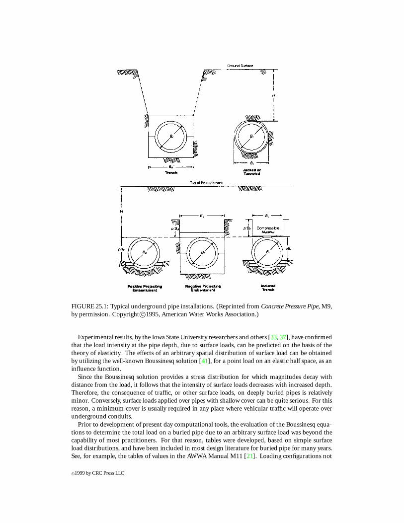
FIGURE 25.1: Typical underground pipe installations. (Reprinted from Concrete Pressure Pipe, M9,by permission. Copyright c©1995, American Water Works Association.)
Experimental results, by the Iowa State University researchers and others [33, 37], have confirmedthat the load intensity at the pipe depth, due to surface loads, can be predicted on the basis of thetheory of elasticity. The effects of an arbitrary spatial distribution of surface load can be obtainedby utilizing the well-known Boussinesq solution [41], for a point load on an elastic half space, as aninfluence function.
Since the Boussinesq solution provides a stress distribution for which magnitudes decay withdistance from the load, it follows that the intensity of surface loads decreases with increased depth.Therefore, the consequence of traffic, or other surface loads, on deeply buried pipes is relativelyminor. Conversely, surface loads applied over pipes with shallow cover can be quite serious. For thisreason, a minimum cover is usually required in any place where vehicular traffic will operate overunderground conduits.
Prior to development of present day computational tools, the evaluation of the Boussinesq equa-tions to determine the total load on a buried pipe due to an arbitrary surface load was beyond thecapability of most practitioners. For that reason, tables were developed, based on simple surfaceload distributions, and have been included in most design literature for buried pipe for many years.See, for example, the tables of values in the AWWA Manual M11 [21]. Loading configurations not
c©1999 by CRC Press LLC

covered by the previously developed tables can be investigated using available software programs.Mathcad [30], for example, can be utilized to carry out the analysis necessary to evaluate the effectof arbitrary surface loads on buried structures, including pipes.
25.2.3 Live Loads
The main source of design live loads on buried pipes is wheeled traffic from highway trucks, railroadlocomotives, and aircraft. Loads transmitted to buried structures by the standard HS-20 truckloading [1] and the Cooper E-80 railroad loading have been evaluated using the Boussinesq solutionand engineering judgment, for varying depths of cover, and are available, in different forms, in severalpublications (see, e.g., [6, 20]). Due to the wide variation in aircraft wheel loadings, it is usuallynecessary to evaluate each case separately. FAA Advisory Circular 150/5320-5B provides informationon aircraft wheel loads. The load intensity at the depth of the pipe has been reported in numerousreferences. Simple load intensities for the HS-20 truck loads and for the Cooper E-80 locomotiveloads, at varying depths, are given in Tables 25.1 and 25.2, respectively [6]. More comprehensivetables for truck and railroad loads have been published [20, 27]. In general, the intensities given inTables 25.1 and 25.2 are close to the intensities given in the other tables, though some differencesdo exist. For examples in this chapter, live loads will be based on the intensities given in Tables 25.1and 25.2. In case of doubt as to appropriate live load values to use in design of buried pipe, the adviceof a geotechnical engineer should be obtained.
TABLE 25.1 HS-20 Live Load
Height of cover, ft Live load, lb/ft2
1 18002 8003 6004 4005 2506 2007 1758 100
Over 8 Neglect
From American Society for Testing andMaterials. 1994. A796. Standard Prac-tice for Structural Design of Corrugated SteelPipe, Pipe-Arches and Arches for Storm andSanitary Sewers and Other Buried Applica-tions. With permission.
25.2.4 Seismic Loads
In zones of high seismicity, buried conduits must be designed for the stresses imposed by earthquakeground motions. The American Society of Civil Engineers (ASCE) has developed procedures forevaluation of the magnitude of axial and flexural strains induced in underground lines by seismicmotions [24]. The document reflects the research efforts of many of the leading seismic engineers inthe country and the methodology is widely used for design of underground conduits of all kinds.
As a general rule, the stresses inpipewalls due to seismicmotion–induced strains arequite small anddo not adversely affect the design. Since most design codes allow for an increase in allowable stress,or a decrease in load factors, when seismic loads are included in a load combination, buried pipesthat are sized to sustain other design loads usually have sufficient strength to resist seismic-imposedstresses.
c©1999 by CRC Press LLC

TABLE 25.2 Cooper E-80 Live Load
Height of cover, ft Live load, lb/ft2
2 38005 24008 160010 110012 80015 60020 30030 100
Over 30 Neglect
From American Society for Testing and Ma-terials. 1994. A796. Standard Practice forStructural Design of Corrugated Steel Pipe, Pipe-Arches and Arches for Storm and Sanitary Sewersand Other Buried Applications. With permis-sion.
Consequently, the major consideration to be addressed in design of underground pipe is notstrength but excessive relative movement. Unrestrained slip joints in buried pipe may be subject torelative movement, between the two segments meeting at a joint, that exceeds the limit of the joint’scapacity to function. For that reason, slip joint pipe must be investigated for maximum relativemovement when subject to seismic motion. Types of pipe commonly utilizing slip joints includeductile iron, reinforced and prestressed concrete, and fiberglass reinforced plastic.
25.3 Internal Loads
25.3.1 Internal Pressure and Vacuum
Underground pipe systems operate under varying levels of internal pressure. Gravity sewer linesnormally operate under fairly low internal pressure whereas water supply mains and industrial processpipes may be subject to internal pressures of several hundred pounds per square inch. High-pressurepipelines are often designed for a continuous operating pressure and for a short-term transientpressure.
Certain operational events may cause a temporary vacuum in buried conduits. In most cases theduration of application of vacuum loading is extremely short and its effects can usually be examinedseparately from other live loads. For design, a hydraulic analysis of the system may be used to predictthe magnitude and time variation of transients in both the positive and negative internal pressure.
25.3.2 Pipe and Contents
The effects of dead weight of the pipe wall and the fluid carried must be resisted by the structuralcapacity of the pipe. Neither of these loads contribute significantly to the overall stress state in mostcircumstances. In practice, loads from these two sources are often neglected in design of steel or plasticpipe, but they are usually included in design of prestressed and reinforced concrete pressure pipe andcan be included in design of concrete nonpressure pipe as well. Formulas for determination of pipewall bending moments and thrust forces, due to self-weight and fluid loads, are available in standardstress analysis references [43]. Since these loads are usually small compared to the overburden, theycan be added to the vertical soil loads for simplicity and with conservatism.
c©1999 by CRC Press LLC

25.4 Design Methods
25.4.1 General
The principal structural consideration in design of buried pipe is the ability to support all imposedloads. Other important items include the type of joints to be used and protection against environ-mental exposure. There are two fundamental approaches to design of buried pipe, based on thepipe’s behavior under load [32, 40]. Pipe that undergoes relatively large deformations under itsgravity loads, and obtains a large part of its supporting capacity from the passive pressure of thesurrounding soil, is referred to as “flexible”. As will be observed, the evaluation of the contributionof the soil to pipe strength is difficult due to varying conditions of pie installation. For that reason,prudence in design must be followed. However, as with most design problems, the engineer must,ultimately, balance conservatism with economic considerations.
Pipes with stiffer walls that resist most of the imposed load without much benefit of engagementof passive soil pressure, because deformation under load is restricted, are called “rigid”. Steel, bothcorrugated and plain plate, ductile iron, and fiberglass reinforced plastic pipes are considered flexible;concrete pipe is considered rigid. Different methodologies are employed in assessing the strength ofeach type.
25.4.2 Flexible Design
Plain Steel
The structural capacity of flexible pipes is evaluated on the basis of resistance to buckling(compressive yield) and vertical diametrical deflection under load. Additionally, for flexible pipes, anonstructural requirement in the form of a minimum stiffness to ensure that the pipe is not damagedduring shipping and handling is normally imposed. In the case of steel pipes designed according tothe recommendations of AWWA Manual M11 [21], the following two equations are used to choosepipe wall thickness sufficient to satisfy the handling requirement:
t ≥ D288 for diameter up to 54 in.
t ≥ D+20400 for diameter greater than 54 in. (25.3)
It is of interest to note that for many years, a minimum thickness of D/200 was used by pipedesigners. In our experience, wall thicknesses meeting this ratio will usually result in designs thatalso satisfy the strengthanddeflectioncriteriadiscussedbelow. Tensile stressesdue to internalpressuremust be limited to a fraction of the tensile yield of the material. AWWA recommends limiting thetensile stress to 50% of yield.
Collapse, or buckling, of flexible pipes is difficult to predict theoretically because of the indetermi-nate nature of the load pattern. AWWA has published an expression for the determination of capacityof a given pipe to support imposed loads. The equation, given as Equation 6-7 in AWWA ManualM11 [21], incorporates the effects of the passive soil resistance, the buoyant effect of groundwater,and the stiffness of the pipe itself. Allowable buckling pressure is given by:
qa =(
1
FS
)(32RwB ′E′ EI
D3
)1/2
(25.4)
whereqa = allowable buckling pressure (psi)FS = factor of safety
= 2.5 for (12h/D) ≥ 2 and
c©1999 by CRC Press LLC

= 3.0 for (12h/D) < 2Rw = water buoyancy factor
= 1-0.33 (hw/h)
h = height of ground surface above top of pipe (ft)hw = height of groundwater surface above top of pipe (ft)D = diameter of pipe (in.)B ′ = coefficient of elastic support
= 11+4e−0.065h
E′ = modulus of soil reaction (psi)E = modulus of elasticity of pipe wall (psi)I = moment of inertia per inch length of pipe wall (in.3)
In case vacuum load and surface live load are both included in the design conditions, AWWArecommends that separate load combinations be considered for each. That is because vacuumloads usually occur only for a short time and the probability of vacuum and maximum surfaceload occurring simultaneously is very small. In particular the following two load cases should beconsidered. For traffic live load:
qa ≥ γwhw + Rw
Wc
D+ WL
D(25.5)
whereγw = specific weight of water (0.0361 lb/in.3)WL = live load on pipe (lb/in. length of pipe)Wc = vertical soil load on pipe (lb/in. length of pipe)For vacuum load:
qa ≥ γwhw + Rw
Wc
D+ Pν (25.6)
wherePν = internal vacuum pressure (psi)
Deflection is determined by the Spangler formula:
1y = Dl
(KWcr
3
EI + 0.061E′r3
)(25.7)
where1y = deflection of pipe (in.)Dl = deflection lag factor (1.0 to 1.5)K = bedding constant (0.1)r = pipe radius (in.)
This form of the deflection equation was obtained by ordinary bending theory of a ring subject toan assumed pattern of applied vertical load, width of vertical reaction, and distribution of horizontalpassive pressure [38, 42] and has been used in pipe design for over 50 years. According to the formula,deflection is limited by the stiffness of the pipe wall itself and by the effect of the passive pressure. It issignificant to note that in the sizes of steel pipes often encountered, the ratio of the two componentsof resistance is on the order of 1:20, with the pipe wall stiffness being the smaller. Therefore, it isobvious that the passive resistance, which is closely related to the type of backfill and its degree ofcompaction, is the dominant influence on the vertical deflection of flexible pipes. That being thecase, it becomes apparent that increasing the strength of a flexible pipe will probably be an inefficientway to properly limit deflection of underground pipe in most cases. The pipe installation must becompleted as specified in order for this to be achieved.
c©1999 by CRC Press LLC
Efforts to quantify the modulus of soil reaction, E′, have continued since the initial developmentof the deflection equation. Suggested values are published in numerous references, including AWWAManual M11 [21]. Values given there range from 200 to 3000 psi. The values depend on the typeand level of compaction of the surrounding soil. Since pipe designers often have little control overthe installation of pipe, historically, a value of E′ in the range of 700 to 1000 psi has been assumedrepresentative of average installations for estimating deflection at time of design.
In a recent work, engineers at the U.S. Bureau of Reclamation addressed the question of deflectionof flexible pipe [27]. Their work, which is based on the wide experience of the Bureau of Reclamationin construction of all kinds of underground pipes, discusses appropriate values of E′ based on notonly the backfill and compaction used, but also the native soil. In addition to the soil modulus values,the authors also give a modified form of the deflection equation that includes a factor to account forlong-term deflection, Tf (which replaces the factorDl in Equation 25.7), and an additional multiplieron the soil modulus, called a design factor, Fd , with values ranging from 0.3 to 1.0. The combinedeffect of these two changes is, generally, to predict larger deflections than with the original Spanglerequation. The revised equation becomes:
1y = Tf
(KWcr
3
EI + 0.061FdE′r3
)(25.8)
whereTf = time lag factorFd = design factor
Values for Spangler’s deflection lag factor, Dl , of 1.0 to 1.5 are recommended; designers usually usethe 1.5 value for conservatism. Since the minimum recommended value for Tf is 1.5, the deflectionsby the modified equation will be higher. Values of the design factor, Fd , are presented for three cases,A, B, and C. The value for case A is 1.0; case B values, which are recommended for design, varyfrom 0.5 to 1.0; and case C values, which are recommended for designs in which deflection is critical,range from 0.3 to 0.75. In all cases the values of Fd increase with quality and level of compaction ofthe backfill.
It follows that control of bedding and backfill of flexible pipes during construction is critical totheir performance. The required passive pressure can be developed only in high-quality fill material,compacted to the proper density. The material surrounding the pipe and extending above the pipefor at least 12 in. should be a well-graded granular stone. Coarse-grained material provides muchhigher passive resistance and, therefore, limits pipe deflection, in flexible pipe systems, more thanfine-grained soil types. Compaction in the lower levels of the pipe is critical. Hand tampers or similarequipment are necessary to ensure that adequate density is obtained in the region below the lowerhaunches of the pipe. Historically, failure to achieve the proper level of compaction in this area ofdifficult accessibility has been identified as a major contributing cause to excessive deformations inflexible pipe construction.
It is common practice to limit the final vertical deflection of unlined pipes to less than 5% ofthe diameter. Deflection of pipes with cement mortar coatings should be limited to 2% of thediameter. Field observations of steel pipes in service indicate that once the deflection reaches 20% ofthe diameter, collapse is imminent.
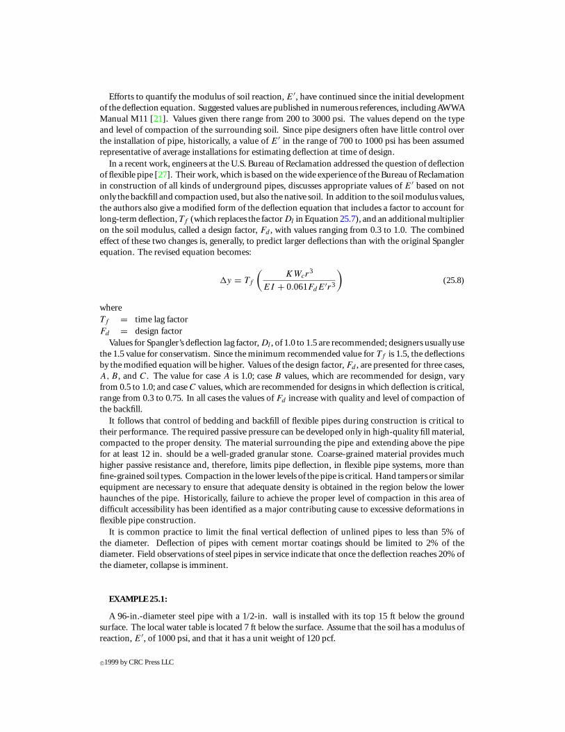
EXAMPLE 25.1:
A 96-in.-diameter steel pipe with a 1/2-in. wall is installed with its top 15 ft below the groundsurface. The local water table is located 7 ft below the surface. Assume that the soil has a modulus ofreaction, E′, of 1000 psi, and that it has a unit weight of 120 pcf.
c©1999 by CRC Press LLC

1. Verify that the pipe will satisfy the buckling and deflection criteria given in AWWA ManualM11 [21].
2. Determine the amount of vacuum load that can be supported by the pipe.
Solution
1. The weight of soil bearing on the pipe is calculated from the prism of soil from the top ofthe pipe to the ground surface:
Wc = γshD
= 120× 15× (96/12) = 14,400 lb/ft
Determine the h/D ratio to obtain the appropriate factor of safety:
h
D= 15
8= 1.875< 2; therefore FS = 3
The groundwater surface is 15− 7 = 8 ft above the top of the pie. The water buoyancyfactor (Rw) and the coefficient of elastic support (E′) are calculated on the basis of thedepth of cover and groundwater:
hw = 8f t
Rw = 1 − 0.33hw
h= 1 − 0.33× 8
15= 0.824
B ′ = 1
1 + 4e−0.065×15= 0.399
The modulus of elasticity for steel is 29× 106 psi; the moment of inertia per inch lengthof pipe is
I = t3
12= 0.53
12= 0.0104 in.3; hence the product EI = 302,083 in.-lb
Therefore, by Equation 25.4, the allowable buckling pressure is
qa =(
1
3
)(32× 0.824× 0.399× 1,000× 302,083
963
)1/2
= 19.968 psi
The total applied load intensity, Q, is given by
Q = γwhw + Rw
Wc
D+ WL
D= 0.0361× 96+ 0.824× 14,400
12× 96+ 0 = 13.766 psi
Since Q < qa , the pipe is safe against buckling. Check deflection:
1y = 1.5
(0.1 × 14,400
12 × 483
302,083+ 0.061× 1,000× 483
)= 2.824 in.
The calculated deflection is approximately 3% of the diameter, less than the 5% usuallyspecified as the limit for unlined pipe.
2. The vacuum pressure that can be supported within the buckling capacity of the pipe isthe difference between the calculated critical buckling capacity, qa , and the applied loadintensity, Q:
Pν = qa − Q = 19.968− 13.766= 6.202 psi
c©1999 by CRC Press LLC

Corrugated Steel
Corrugated steel has the advantage of greater flexural strength per unit weight of material thanplain steel, and has been widely used in surface drainage systems and to a lesser extent in processwater systems. In this form, the pipe is assembled from corrugated sheets, rolled to radius and boltedor riveted together.
Corrugated steel pipes can be designed according to ASTM standard practice A796 (AmericanSociety for Testing and Materials). The practice covers both curve and tangent (“sinusoidal”) wallsand smooth walls with helical ribs of rectangular section at regular intervals for increased strength. Aswith plain steel pipe, this design procedure requires a minimum stiffness in the pipe wall for shippingand handling. To make a quantitative evaluation of the degree of stiffness, a flexibility factor, definedfor all wall configurations as
FF = D2
EI(25.9)
whereFF = flexibility factor (in.-lb−1)D = pipe diameter (in.)E = modulus of elasticity (psi)I = moment of inertia of wall cross-section per inch (in.3)is subject to limits depending on the corrugation configuration and the type of installation. Forexample, in configurations of sinusoidal corrugations, specified in ASTM A760 and A761 [4, 5],values of the flexibility factor are restricted to 0.020 to 0.060.
The phenomenon of buckling of buried corrugated pipes has been investigated, through prototypetesting, by Watkins [3]. Design curves utilizing the results of that research were originally publishedin an American Iron and Steel Institute (AISI) design manual [3] and have been continued into thecurrent edition of the book. The curves provide buckling loads for corrugated steel–walled pipes asa function of diameter-to-radius of gyration ratio. The design equations given in ASTM A796 [6]are of the same general form as the design curves developed by AISI. That is, there are three ranges ofbehavior—elastic buckling, inelastic buckling, and yield—and the dependence of the expressions onthe independent variable, D/r , is the same in the two regimes of the formulas in both documents.The principal difference between the two approaches is the inclusion of an explicit dependence onsoil stiffness in the ASTM A796 equations. The AISI formulas, on the other hand, account for soilstiffness by reduction in applied load for well-compacted backfills.
The applicable formulas for critical buckling stress, as given in ASTM A796 [6], and their applicableranges of diameter-to-radius of gyration ratio are given below:
fc = fu − f 2u
48E
(kD
r
)2
forkD
r≤√
24E
fu
fc = 12E(kDr
)2 forkD
r>
√24E
fu
(25.10)
subject to the provision that:fc ≤ fy (25.11)
wherefc = critical buckling stress (psi)fy = specified minimum yield stress (psi)fu = specified minimum ultimate stress (psi)k = soil stiffness factor = 0.22 for material at 90% density
c©1999 by CRC Press LLC

E = modulus of elasticity (psi)D = pipe diameter (in.)r = radius of gyration of pipe wall (in.)
The buckling formulas in ASTM A796 [6] also are given in the AASHTO (American Associationof State Highway and Transportation Officials) specification for design of highway bridges [1].
The corresponding equations provided in the AISI handbook [3] are
fc = 40,000− 0.081
(D
r
)2
for 294<D
r< 500
fc = 4.93× 10⁹(Dr
)2 forD
r> 500 (25.12)
with, again, the provision that the critical buckling stress cannot exceed the yield stress, fy .A comparison of the two sets of formulas can be made to determine the maximum variation. The
soil parameter, k, obviously affects the results. InASTMA796[6], a valueofk = 0.22is recommendedfor good fill material compacted to 90% of standard density; no suggestions are provided for otherbackfill conditions. The AISI expressions for critical buckling stress (Equation 25.12) do not containany dependence on the degree of compaction of the surrounding soil. However, the handbookdoes recommend load factors, which multiply the applied loads, that are related to the degree ofcompaction. For example, the recommended load factor for 90% compaction is 0.75. Use of a loadfactor of 0.75 has the same effect as increasing the allowable stress by 1.33. If the results from theASTM and AISI equations are compared on that basis, the values are within 10%. On the otherhand, if a load factor of 1.0, which corresponds to a density of only 80% standard, is used, the soilstiffness, k, must be increased to 0.26 for the two sets of formulas to give approximately the sameresults. Clearly, use of the higher value for k results in a slightly more conservative design, and thatmay be desirable, in view of the normally unknown character of the actual installed backfill.
In either case, the appropriate wall cross-section must be selected to satisfy
Wc
2A≤ fc
(SF )(25.13)
whereA = cross-section area of wall per unit lengthSF = safety factor = 2Wc = vertical load per unit length of pipe (Note: Wc must be multiplied by the appropriate load
factor if the AISI equations are used)It is of interest to note the D/r ratios that form the transition between elastic and inelastic and
between buckling and yield behavior in the ASTM A796 equations. For pipe meeting ASTM A760,maximum thickness of 0.168 in., the specified minimum yield and ultimate stress are 33 ksi and 45ksi, respectively. For those values, elastic buckling controls design for D/r ratios greater than 478and yield controls for D/r ratios less than 350, for k equal to 0.26. These values correspond fairlyclosely with the AISI limits of 500 and 294, respectively.
EXAMPLE 25.2:
Consider the pipe in Example 25.1. Determine the minimum wall thickness of 3 in. x 1 in. corru-gated pipe that will satisfy the buckling expressions of Equation 25.10 and the handling requirementof Equation 25.9 with FF limited to a maximum value of 0.033. Assume a value of k of 0.26. Also,the minimum specified yield (fy) and ultimate (fu) stresses for the material are 33,000 and 45,000psi, respectively.
c©1999 by CRC Press LLC

Solution The radius of gyration for all thicknesses in the 3 × 1 series range from 0.3410to 0.3499 in. (see Table 25.3).
Therefore, in the calculations user = 0.34 in.
It follows that
kD
r= 0.26× 96
0.34= 52.8
√24E
fu
=√
24× 29× 106
45,000= 124.4
Since kDr
<√
24Efu
, the first of Equation 25.10 must be used:
fc = fu − f 2u
48E
(kD
r
)2
= 45,000− 45,0002
48× 29× 106
(0.26× 96
0.34
)2
= 37,160 psi > fy
Since the calculated buckling stress exceeds the yield, the critical stress is the yield stress, 33,000 psi.The required wall area per foot of length can be determined by rearrangement of Equation 25.13:
A = Wc
2 fc
(SF )
= 14,400
2 × 33,0002
= 0.437 in.2
The lightest section, thickness of 0.052 in., will satisfy the stress requirement. Check the handlingrequirement. The moment of inertia per inch of wall is 6.892× 10⁻³ in.3:
FF = D2
EI= 962
(29× 106) × (6.892× 10−3)= 0.046> 0.033
Since the flexibility factor is too large, try the next section in the series, the 0.064-in. thickness, andI = 8.658× 10⁻³ in.3:
FF = D2
EI= 962
(29× 106) × (8.658× 10−3)= 0.037> 0.033
Since the flexibility is still too great, the next section in the series, with a thickness of 0.079 in. andflexibility factor of 0.029 is chosen. This example demonstrates a condition that occurs quite oftenin the design of flexible pipes; if the handling and installation minimum stiffness requirements aremet, the strength requirements are automatically taken care of.
Fiberglass Reinforced Plastic
Fiberglass reinforced plastic (FRP) pipe is fabricated by winding glass strands into a matrix oforganic resin on a mandrel of the desired diameter. A variation on the fiberglass-resin matrix utilizescementofpolymermortar incorporated into the structure toadd stiffness andreduce costofmaterials.ASTM standards D3262 [9], D3517 [10], and D3754 [11], and AWWA standard C950 [19] providerequirements for manufacture of both the fiberglass-resin and the mortar pipe in diameters up to 144in. Structural strength and rigidity against external loads for this type of pipe are established by loadtests performed as specified by ASTM D2412 [8]. In the load test, equal and opposite concentratedloads are applied on opposite ends of a diameter. Load deflection data are obtained from whichstiffness and related buckling strength of the pipe can be determined.
Each of the mentioned pipe specifications provides for levels of pipe stiffness (PS) of 9, 18, 36,and 72 psi. These values represent applied force per unit length of pipe divided by deflection. Use of
c©1999 by CRC Press LLC
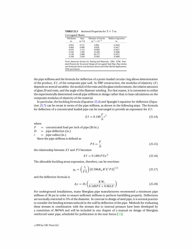
TABLE 25.3 Sectional Properties for 3 × 1 in.
Corrugated SheetsThickness Area Moment of inertia Radius of gyration
in. in.2/ft in.3 × 10−3 in.
0.052 0.711 6.892 0.34100.064 0.890 8.658 0.34170.079 1.113 10.883 0.34270.109 1.560 15.458 0.34480.138 2.008 20.175 0.34720.168 2.458 25.083 0.3499
From American Society for Testing and Materials. 1994. A796. Stan-dard Practice for Structural Design of Corrugated Steel Pipe, Pipe-Archesand Arches for Storm and Sanitary Sewers and Other Buried Applications.With permission.
the pipe stiffness and the formula for deflection of a point-loaded circular ring allows determinationof the product, EI , of the composite pipe wall. In FRP construction, the modulus of elasticity (E)
depends on several variables: the moduli of the resin and the glass reinforcement, the relative amountsof glass 20 and resin, and the angle of the filament winding. For that reason, it is convenient to utilizethe experimentally determined overall pipe stiffness in design rather than to base calculations on thecomposite modulus of elasticity of the material.
In particular, the buckling formula (Equation 25.4) and Spangler’s equation for deflection (Equa-tion 25.7) can be recast in terms of the pipe stiffness, as shown in the following steps. The formulafor deflection of a concentrated loaded pipe can be rearranged to provide an expression for EI :
EI = 0.149F
1r3 (25.14)
whereF = concentrated load per inch of pipe (lb/in.)D = pipe deflection (in.)r = pipe radius (in.)
Since the pipe stiffness is defined as
PS = F
1(25.15)
the relationship between EI and PS becomes
EI = 0.149(PS)r3 (25.16)
The allowable buckling stress expression, therefore, can be rewritten:
qa =(
1
FS
) (0.596RwB ′E′PS
)1/2(25.17)
and the deflection formula is
1y = Dl
(KWc
0.149PS + 0.061E′
)(25.18)
For underground installations, many fiberglass pipe manufacturers recommend a minimum pipestiffness of 36 psi in order to ensure sufficient stiffness to perform backfilling properly. Deflectionsare normally restricted to 5% of the diameter. In contrast to design of steel pipe, it is normal practiceto consider the bending stresses induced in the wall by deflection of the pipe. Methods for evaluatingthese stresses in combination with the stresses due to internal pressure have been developed bya committee of AWWA and will be included in one chapter of a manual on design of fiberglassreinforced water pipe, scheduled for publication in the near future [22].
c©1999 by CRC Press LLC

25.4.3 Rigid Design
Concrete Pressure Pipe
Concrete pipe can be used for both pressure and nonpressure applications. It offers the advan-tage of being corrosion resistant in conditions where steel might be attacked, and in some instancesit may be a more cost-effective solution than steel or plastic.
When concrete pipe is used in high-pressure systems, prestressed concrete pipe is the type mostoften selected. The pipe is manufactured in diameters from 24 to 144 in. and is fabricated with wallsfrom 4 to 12 in. thick. A steel cylinder, usually of 16-gal thickness, is embedded in the wall for leakprotection. The outer surface of the wall is wrapped with high-strength wire under tensile stressesin the 175–200 ksi range. The prestressing places the concrete wall into compression of sufficientmagnitude so that it will not be fully relieved under design internal pressure loadings. Finally, acoat of sand-cement mortar is applied over the prestressing wires to provide corrosion protection. Acomprehensive design procedure for this type of pipe is contained in AWWA C304 [17]. Prestressedpipe is normally designed only by pipe manufacturers. The design provisions meet AWWA C304and the actual pipe is fabricated according to AWWA C301 [14]. Pipe purchasers must indicate thedesign pressures, including transients, installation conditions, and surface loads.
Reinforced concrete pipe can be designed to sustain internal pressure loads, but the maximumpressures that can be carried are significantly less than with prestressed pipe and its use in suchapplications is limited. AWWA C300, C302, and C303 [13, 15, 16] are all specifications covering thedesign and fabrication of reinforced concrete pressure pipe in differing configurations of reinforcingand with or without the steel cylinder pressure boundary. Design procedures for all three specifica-tions are presented in AWWA Manual M9 [20] and the interested reader is encouraged to review thatmanual for details. As with prestressed pipe, the pipe specifier usually supplies only the performanceattributes and the pipe fabricator performs the design to meet the appropriate specification.
Concrete Nonpressure Pipe
ASTM C76 [7] contains specification requirements for reinforced concrete pipe not intendedfor pressure applications. Five classes of pipe, classes I–V, respectively, representing five levels ofstructural strength, are specified. The strength is characterized by the concentrated load requiredto cause a crack of 0.01 in. width and the ultimate concentrated load. Load values are determinedexperimentally by the three-edge-bearing test. The test simulates concentrated loads applied atopposite ends of a pipe diameter. These loads are referred to as D-loads (D0.01 and Dult): theconcentrated force per unit length of pipe per unit length of diameter necessary to cause either the10-mil-width crack or ultimate failure of the pipe. D-load values for the five pipe classes included inASTM C76 are shown in Table 25.4.
In determination of the strength required to resist external loads, the total pipe load is estimatedby standard methods. Bedding factors, based on the type of installation, the soil type, and its levelof compaction, have been developed by the American Concrete Pipe Association [2]. These factorsrepresent the ratio of the maximum bending moment due to a concentrated load to the momentcaused by the actual live and dead load of the same magnitude as the concentrated load.
ACPA has defined four standard installation types, for which relevant information is shown inTables 25.5 and 25.6. Bedding factors for embankment installations are given in Table 25.7. Otherbedding factors, for trench installations and for live load effects, have also been obtained by ACPAbut are not reproduced here. It is noted that ACPA recommends using the dead load factor for liveload contributions as well, if the tabulated live load factor is larger than the dead load factor. Thecalculation methodology used to obtain the various factors is described in the ACPA design data [2].
Use of the appropriate bedding factor allows the conversion of the actual load to an equivalent pointload. Comparison of that equivalent load with standard D-loads is used to establish the appropriateclass of pipe with sufficient capacity to support the design loads. Normal procedure is to utilize a
c©1999 by CRC Press LLC
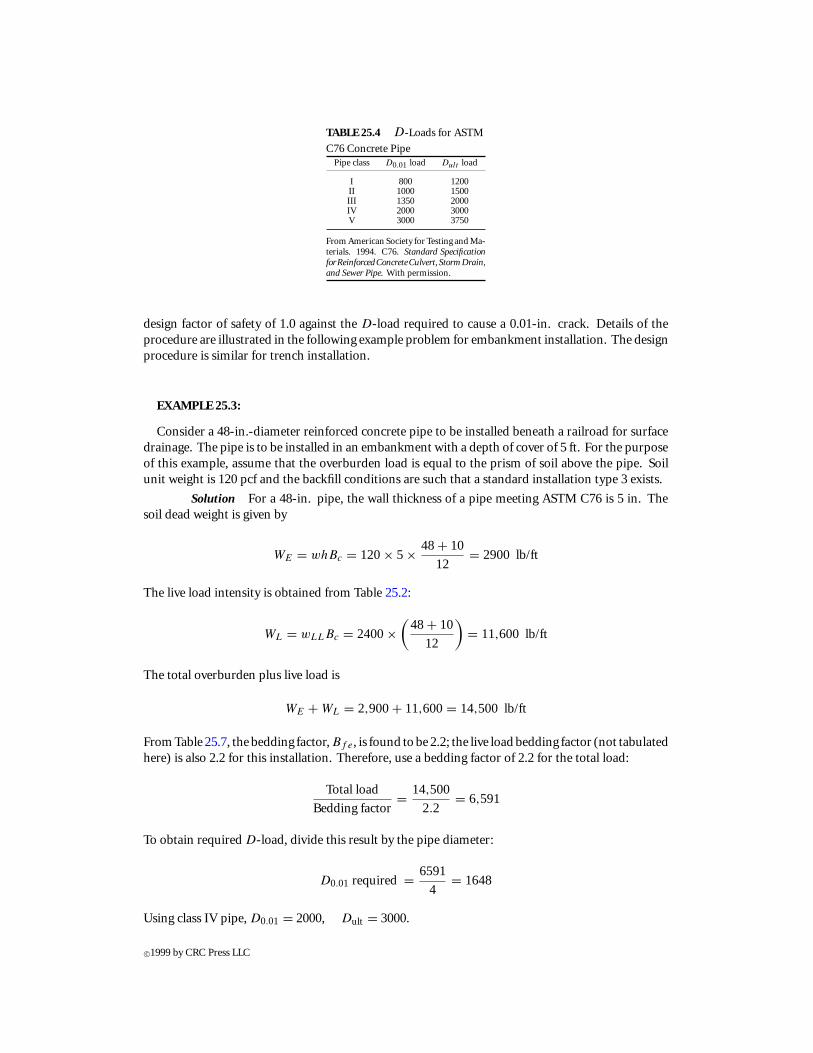
TABLE 25.4 D-Loads for ASTM
C76 Concrete PipePipe class D0.01 load Dult load
I 800 1200II 1000 1500III 1350 2000IV 2000 3000V 3000 3750
From American Society for Testing and Ma-terials. 1994. C76. Standard SpecificationforReinforcedConcreteCulvert, StormDrain,and Sewer Pipe. With permission.
design factor of safety of 1.0 against the D-load required to cause a 0.01-in. crack. Details of theprocedure are illustrated in the following example problem for embankment installation. The designprocedure is similar for trench installation.
EXAMPLE 25.3:
Consider a 48-in.-diameter reinforced concrete pipe to be installed beneath a railroad for surfacedrainage. The pipe is to be installed in an embankment with a depth of cover of 5 ft. For the purposeof this example, assume that the overburden load is equal to the prism of soil above the pipe. Soilunit weight is 120 pcf and the backfill conditions are such that a standard installation type 3 exists.
Solution For a 48-in. pipe, the wall thickness of a pipe meeting ASTM C76 is 5 in. Thesoil dead weight is given by
WE = whBc = 120× 5 × 48+ 10
12= 2900 lb/ft
The live load intensity is obtained from Table 25.2:
WL = wLLBc = 2400×(
48+ 10
12
)= 11,600 lb/ft
The total overburden plus live load is
WE + WL = 2,900+ 11,600= 14,500 lb/ft
From Table 25.7, the bedding factor, Bf e, is found to be 2.2; the live load bedding factor (not tabulatedhere) is also 2.2 for this installation. Therefore, use a bedding factor of 2.2 for the total load:
Total load
Bedding factor= 14,500
2.2= 6,591
To obtain required D-load, divide this result by the pipe diameter:
D0.01 required = 6591
4= 1648
Using class IV pipe, D0.01 = 2000, Dult = 3000.
c©1999 by CRC Press LLC
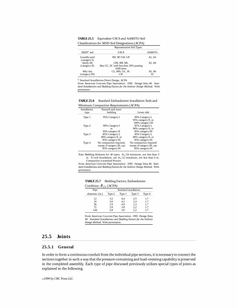
TABLE 25.5 Equivalent USCS and AASHTO Soil
Classifications for SIDD Soil Designations (ACPA)Representative Soil Types
SIDDa soil USCS AASHTO
Gravelly sand SW, SP, GW, GP A1, A3(category I)Sandy silt GM, SM, ML A2, A4
(category II) Also GC, SC with less then 20% passing#200 sieve
Silty clay CL, MH, GC, SC A5, A6(category III) CH A7
a Standard Installations Direct Design, ACPAFrom American Concrete Pipe Association. 1995. Design Data 40. Stan-dard Installations and Bedding Factors for the Indirect Design Method. Withpermission.
TABLE 25.6 Standard Embankment Installation Soils and
Minimum Compaction Requirements (ACPA)Installation Haunch and outer
type bedding Lower side
Type 1 95% Category I 90% Category I,95% category II, or100% category III
Type 2 90% Category I 85% Category I,or 90% category II, or
95% category II 95% category IIIType 3 85% Category I, 85% Category I,
90% category II, or 90% category II, or95% category III 95% category III
Type 4 No compaction required, No compaction requiredexcept if category III, use except if category III, use
85% category III 85% category III
Note: Bedding thickness for all types: Do/24 minimum, not less than 3in. If rock foundation, use Do/12 minimum, not less than 6 in.Compaction is standard Proctor.
From American Concrete Pipe Association. 1995. Design Data 40. Stan-dard Installations and Bedding Factors for the Indirect Design Method. Withpermission.
TABLE 25.7 Bedding Factors, Embankment
Condition, Bf e (ACPA)Pipe Standard installation
diameter, (in.) Type 2 Type 1 Type 3 Type 4
12 3.2 4.4 2.5 1.724 3.0 4.2 2.4 1.736 2.9 4.0 2.3 1.772 2.8 3.8 2.2 1.7144 2.8 3.6 2.2 1.7
From American Concrete Pipe Association. 1995. Design Data40. Standard Installations and Bedding Factors for the IndirectDesign Method. With permission.
25.5 Joints
25.5.1 General
In order to form a continuous conduit from the individual pipe sections, it is necessary to connect thesections together in such a way that the pressure-containing and load-resisting capability is preservedin the completed assembly. Each type of pipe discussed previously utilizes special types of joints asexplained in the following.
c©1999 by CRC Press LLC

25.5.2 Joint Types
Plain Steel
In plain steel plate pipe, the individual pipe sections are fabricated from plate, rolled to theproper radius, and welded together. Joints, in fabricated sections, are either continuous helical orlongitudinal. When installed, the sections are welded together using either bell-and-spigot or buttjoints.
In plain steel pipe, full penetration butt welds are used extensively for field joints. In waterworks construction, welding of pipelines is covered by AWWA C206 [12]. That standard requiresthat welding procedures and welding operators be prequalified before use on a job. In addition,tolerances on fit-up are specified and inspection requirements are set out. Strict adherence to projectspecifications is necessary to guarantee that the desired continuity is obtained at the junction.
Although connecting pipe segments by use of full-penetration butt welds has enjoyed wide ac-ceptance in pipeline construction, bell-and-spigot joints, fillet welded, may also be used. Thesejoints require only fillet welds and are generally considered to be less expensive to install than thefull-penetration butt weld. However, due to the inherent eccentricity in such joints, a potential forfailure exists under certain temperature conditions when longitudinal tensile stresses are developed.Some failures of welded bell-and-spigot joints were reported in the technical literature a few yearsago [26, 31]. Since that time, requirements for welding of bell-and-spigot joints in steel pipe inAWWA C206 [12] have been revised to minimize the potential for failure in this type of joint.
Corrugated Steel
The field joints used in corrugated steel are usually made by bolting, either in lap joints or withcoupling bands that fit over two adjacent sections. In most cases, gaskets should be used at joints toprovide leak tightness.
Fiberglass Reinforced Plastic
Several typesof joints areused infiberglass pipe. Couplingorbell-and-spigot jointswithO-ringgaskets (see Figure 25.2) and mechanical couplings, for unrestrained joints, are specified by the ASTMfiberglass pipe specifications mentioned previously. These joints can be used with restraining devices,such as tie rods, if necessary. In addition, continuous hand lay-up joints consisting of alternatinglayers of glass fabric and resin or adhesive-bonded bell-and-spigot joints are used for joints that mustresist longitudinal force as well as contain the pressure exerted by the fluid carried.
FIGURE 25.2: Bell-and-spigot and coupling joints for fiberglass pipe. (From American Society forTesting and Materials. 1991. D3517. Standard Specification for “Fiberglass” Glass-Fiber-ReinforcedThermosetting-Resin Pressure Pipe. With permission.)
Prestressed Concrete
In straight runs of prestressed concrete pressure pipe, the most common joint type is the bell-and-spigot slip-on joint with a rubber O-ring gasket (see Figure 25.3). When making the joint, careshould be used to ensure that the gasket is in its proper place and that the mating ends are properlylocated with respect to each other. The exterior of the joint should be filled with flowable sand-cement
c©1999 by CRC Press LLC
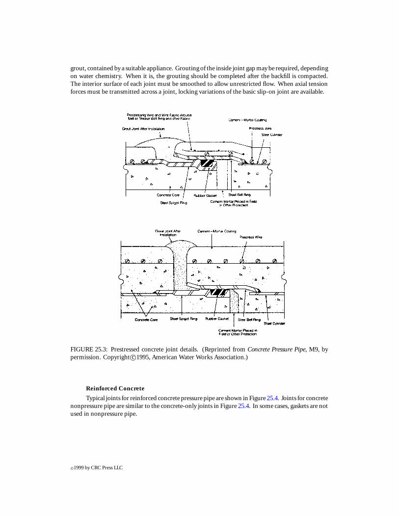
grout, contained by a suitable appliance. Grouting of the inside joint gap may be required, dependingon water chemistry. When it is, the grouting should be completed after the backfill is compacted.The interior surface of each joint must be smoothed to allow unrestricted flow. When axial tensionforces must be transmitted across a joint, locking variations of the basic slip-on joint are available.
FIGURE 25.3: Prestressed concrete joint details. (Reprinted from Concrete Pressure Pipe, M9, bypermission. Copyright c©1995, American Water Works Association.)
Reinforced Concrete
Typical joints for reinforced concrete pressure pipe are shown in Figure 25.4. Joints for concretenonpressure pipe are similar to the concrete-only joints in Figure 25.4. In some cases, gaskets are notused in nonpressure pipe.
c©1999 by CRC Press LLC

FIGURE 25.4: Joint details for reinforced concrete pipe. (Reprinted from Concrete Pressure Pipe, M9,by permission. Copyright c©1995, American Water Works Association.)
25.5.3 Hydrostatic Testing
A field hydrostatic test is usually performed to verify that all joints are watertight. Test pressureshould exceed the maximum design pressure, including transients, by at least 25%. Leakage throughwelded joints should be virtually nonexistent. It is common to allow a slight leakage rate for O-ringgasketed joints (AWWA, C600).
25.6 Corrosion Protection
There are three environmental agents that exert strong influence on corrosion of the pipe wall materialinburied installations. These are thewater, orotherfluid, carried, the soil in contactwith thepipe, andthe groundwater. In the case of certain process water systems, such as power plant condenser coolingsystems, the water may be circulated continuously within a closed loop using cooling towers, lakes,or other means of exhausting heat. When closed systems are used, even in fresh water environments,the concentrations of certain compounds in the water may increase and cause elevated corrosionrates in steel pipes. Chlorides are generally believed to be the most aggressive compounds, normallyfound in water sources, in regard to corrosion of steel. Chlorides can also be harmful to concretepipes, posing threats to the concrete itself and to steel reinforcing. Sulfates are not usually associatedwith steel corrosion, but they can be detrimental to concrete.
Once-through systems, on the other hand, are usually less corrosive for steel pipes and less harmfulto concrete than the closed-cycle systems. When brackish water is used for cooling, positive stepsmust be taken to ensure that corrosion is controlled.
While the process water carried may promote corrosion or other damage on the inside of the pipe,the outside surface may be attacked by the surrounding soil, the groundwater, or both. Soils with low
c©1999 by CRC Press LLC

electrical resistivity may help advance corrosion in steel. Soils that have sulfate compounds abovecertain critical levels can cause damage to concrete pipe. The groundwater can have the same effectson the exterior of the pipe as the process fluid has on the inside. Specifically, groundwater with highchloride or sulfate contents may be harmful to the pipe material.
Because of the wide range of possibilities for the existence of detrimental chemical action, it isessential that the nature of the external and internal environments of the pipe be evaluated in thedesign process. Chemical analyses of the process water and the groundwater are essential. Also,chemical analysis of the soil and resistivity survey results must be available in order to make the bestchoice of pipe system to withstand the exposure throughout the design life of the facility.
25.6.1 Coatings
Coatings can be used to inhibit corrosion or other forms of deterioration in both concrete and steelpipes. Type and extent of coatings depends on the service environment. Steel pipes are almost alwayscoated externally. Coal tar enamel and wrapping has been used successfully in the U.S. for decades.Epoxies and urethanes, among others, have become popular in more recent times.
Cement mortar coatings may be applied to both the interior and exterior of steel pipes. This typeof coating offers several advantages and has an extensive record of satisfactory service. When exteriorcoating of prestressed concrete pipes is desired, certain epoxies are acceptable. Because prevention ofcorrosion in the prestressing wires is so important, pipe designers sometimes specify an additionalcoating to supplement the protection furnished by the cement mortar coating.
25.6.2 Cathodic Protection
Protection against corrosion may, in certain circumstances, require a cathodic protection system. Forexample, cathodic protection has proven to be very successful in providing leak-free high-pressureoil and natural gas pipelines throughout the U.S. Power plant sites have widely dispersed groundingsystems, which can cause unpredictable stray currents that may promote steel corrosion. Cathodicprotection must be designed by competent engineers based on information regarding the extentof buried facilities, the soil resistivity measurements, and the plant grounding system. Electricalcontinuity should be provided on prestressed concrete pipe if present or future installation of cathodicprotection is a possibility.
References
[1] American Association of State Highway and Transportation Officials (AASHTO). 1992. Stan-dard Specifications for Highway Bridges. 15th ed.
[2] American Concrete Pipe Association (ACPA). 1995. Design Data 40. Standard Installationsand Bedding Factors for the Indirect Design Method.
[3] American Iron and Steel Institute (AISI). 1977. Handbook of Steel Drainage & HighwayConstruction Products.
[4] American Society for Testing and Materials (ASTM). 1993. A760. Standard Specification forCorrugated Steel Pipe, Metallic Coated for Sewers and Drains.
[5] American Society for Testing and Materials (ASTM). 1990. A761. Standard Specification forCorrugated Steel Structural Plate, Zinc-Coated, for Field-Bolted Pipe, Pipe-Arches, andArches.
[6] American Society for Testing and Materials (ASTM). 1994. A796. Standard Practice for Struc-tural Design of Corrugated Steel Pipe, Pipe-Arches and Arches for Storm and Sanitary Sewersand Other Buried Applications.
c©1999 by CRC Press LLC
[7] American Society for Testing and Materials (ASTM). 1994. C76. Standard Specification forReinforced Concrete Culvert, Storm Drain, and Sewer Pipe.
[8] American Society for Testing and Materials (ASTM). 1993. C2412. Standard Test Method forDetermination of External Loading Characteristics of Plastic Pipe by Parallel-Plate Loading.
[9] American Society for Testing and Materials (ASTM). 1993. D3262. Standard Specification for“Fiberglass” (Glass-Fiber-Reinforced Thermosetting-Resin Sewer Pipe).
[10] American Society for Testing and Materials (ASTM). 1991. D3517. Standard Specification for“Fiberglass” (Glass-Fiber-Reinforced Thermosetting-Resin Pressure Pipe).
[11] American Society for Testing and Materials (ASTM). 1991. D3754. Standard Specificationfor “Fiberglass” (Glass-Fiber-Reinforced Thermosetting-Resin Sewer and Industrial PressurePipe).
[12] American Water Works Association (AWWA). 1991. C206. Standard for Field Welding of SteelWater Pipe.
[13] American Water Works Association (AWWA). 1989. C300. Standard for Reinforced ConcretePressure Pipe, Steel-Cylinder Type, for Water and Other Liquids.
[14] American Water Works Association (AWWA). 1992. C301. Standard for Prestressed ConcretePressure Pipe, Steel-Cylinder Type, for Water and Other Liquids.
[15] American Water Works Association (AWWA). 1987. C302. Standard for Reinforced ConcretePressure Pipe, Noncylinder Type, for Water and Other Liquids.
[16] American Water Works Association (AWWA). 1987. C303. Standard for Reinforced ConcretePressure Pipe, Steel Cylinder Type, Pretensioned, for Water and Other Liquids.
[17] American Water Works Association (AWWA). 1992. C304. Standard for Design of PrestressedConcrete Cylinder Pipe.
[18] American Water Works Association (AWWA). 1987. C303. Standard for Installation of Ductile-Iron Water Mains and Their Appurtenances.
[19] American Water Works Association (AWWA). 1988. C950. Standard for Fiberglass PressurePipe.
[20] American Water Works Association (AWWA). 1995. Manual M9. Concrete Pressure Pipe.[21] American Water Works Association (AWWA). 1989. Manual M11. Steel Pipe-A Guide for
Design and Installation.[22] American Water Works Association (AWWA). 1997 (projected). Manual M45. Fiberglass Pres-
sure Pipe.[23] Anton, W.F., J.E. Herold, R.T. Dailey, and W.J. Cichanski. 1990. Investigation & Rehabilitation
of Seattle’s Tolt Pipeline. Proceedings of the International Conference on Pipeline Design andInstallation. ASCE. Las Vegas. pp. 213–229.
[24] Committee on Seismic Analysis of the ASCE Structural Division Committee on Nuclear Struc-tures and Materials. 1983. Seismic Response of Buried Pipes and Structural Components.American Society of Civil Engineers (ASCE).
[25] Doyle, J.M. and S.L. Chu. 1968. Plastic Design of Flexible Conduits. J. of Structural Division(ASCE), 94, 1935–1944.
[26] Eberhardt, A. 1990. 108-in. Diameter Steel Water Conduit Failure and Assessment of AWWAPractice. J. of Performance of Constructed Facilities (ASCE), 4, 30–50.
[27] Howard, A.K., L.A. Kinney, and R.P. Fuerst. 1995. Method for Prediction of Flexible PipeDeflection. Report M-25 (M0250000.995). U.S. Bureau of Reclamation. Denver, CO.
[28] Marston, A. and A.O. Anderson. 1913. The Theory of Loads on Pipes in Ditches and Tests ofCement and Clay Drain Tile and Sewer Pipe. Bull. 31. Iowa Engineering Experiment Station.Ames, IA.
[29] Marston, A. 1930. The Theory of External Loads on Closed Conduits in the Light of the LatestExperiments. Bull. 96. Iowa Engineering Experiment Station. Ames, IA.
[30] MathSoft Inc. 1994. Mathcad PLUS 5.0. MathSoft Inc. Cambridge, MA.
c©1999 by CRC Press LLC

[31] Moncarz, P.D., J.C. Shyne, and G.K. Derbalian. 1987. Failures of 108-inch Steel Pipe WaterMain. J. of Performance of Constructed Facilities (ASCE), 1, 168–187.
[32] Netzel, R.J. and J.M. Doyle. 1983. Design of Underground Pipelines. Proc. American PowerConference, 45, 792.
[33] Newmark, N.M. 1935. Simplified Computation of Vertical Pressures in Elastic Foundations.Circular No. 24. Engineering Experiment Station. University of Illinois. Urbana, IL.
[34] Schlick, W.J. 1932. Loads on Pipe in Wide Ditches. Bull. 108. Iowa Engineering Station. Ames,IA.
[35] Schlick, W.J. 1952. Loads on Negative Projecting Conduits. Proc. Highway Research Board, 31,308.
[36] Spangler, M.G., R. Winfrey, and C. Mason. 1926. Experimental Determination of Static andImpact Loads Transmitted to Culverts. Bull. 76. Iowa Engineering Experiment Station. Ames,IA.
[37] Spangler, M.G. and R.L. Hennessy. 1946. A Method of Computing Live Loads Transmitted toUnderground Conduits. Proc. Highway Research Board, 26, 83.
[38] Spangler, M.G. 1941. The Structural Design of Flexible Pipe Culverts. Bull. 153. Iowa Engineer-ing Experiment Station. Ames, IA.
[39] Spangler, M.G. 1950. A Theory of Loads on Negative Projecting Conduits. Proc. HighwayResearch Board, 29, 153.
[40] Spangler, M.G. and R.L. Handy. 1982. Soil Engineering. 4th ed. Harper & Row.[41] Timoshenko, S. and J.N. Goodier. 1951. Theory of Elasticity. McGraw-Hill, New York.[42] Watkins, R.K. and M.G. Spangler. 1958. Some Characteristics of the Modulus of Passive Resis-
tance of Soil: A Study in Similitude. Proc. Highway Research Board, 37, 576.[43] Young, W.C.1989. Roark’s Formulas for Stress & Strain. 6th ed. McGraw-Hill, New York.
c©1999 by CRC Press LLC