ituppsala universitet advanced computer graphics filip malmberg filip @cb.uu.se
TRANSCRIPT
UU/IT
08-01-29 | #2@ UU/IT
Todays lecture Rendering transparent surfaces Texture Mapping Volume rendering
UU/IT
08-01-29 | #3@ UU/IT
Visualizing volume data Surface Rendering We assume that data to
be visualized can be modelled by surfaces. Normally, we model the object with geometric primitives such as points, lines, triangles or polygons and use standard Computer Graphics techniques to render the data
Volume Rendering operates on the data itself and takes into account the changing properties inside the object
UU/IT
08-01-29 | #4@ UU/IT
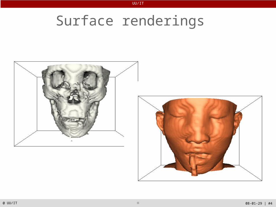
Surface renderings
UU/IT
08-01-29 | #5@ UU/IT
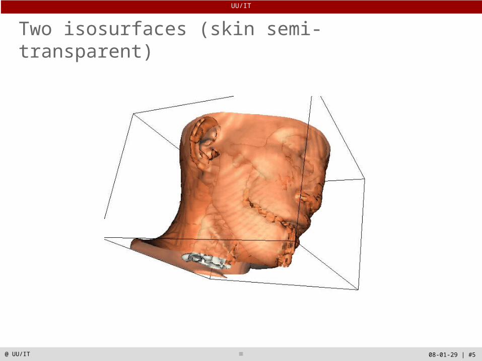
Two isosurfaces (skin semi-transparent)

UU/IT
08-01-29 | #6@ UU/IT
Transparency and Alpha Values
• Opaque objects reflect, scatter, or absorb light at their surface – no light is transmitted
• Transparency and its complement opacity are referred to as alpha in computer graphics
• On graphics cards the frame buffer can store the alpha value along with the RGB values

UU/IT
08-01-29 | #7@ UU/IT
Light transmission in the real world
UU/IT
08-01-29 | #8@ UU/IT
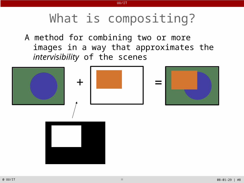
What is compositing?
A method for combining two or more images in a way that approximates the intervisibility of the scenes
+ =
UU/IT
08-01-29 | #9@ UU/IT
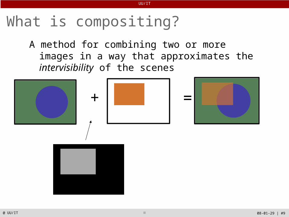
What is compositing?
A method for combining two or more images in a way that approximates the intervisibility of the scenes
+ =
UU/IT
08-01-29 | #10@ UU/IT
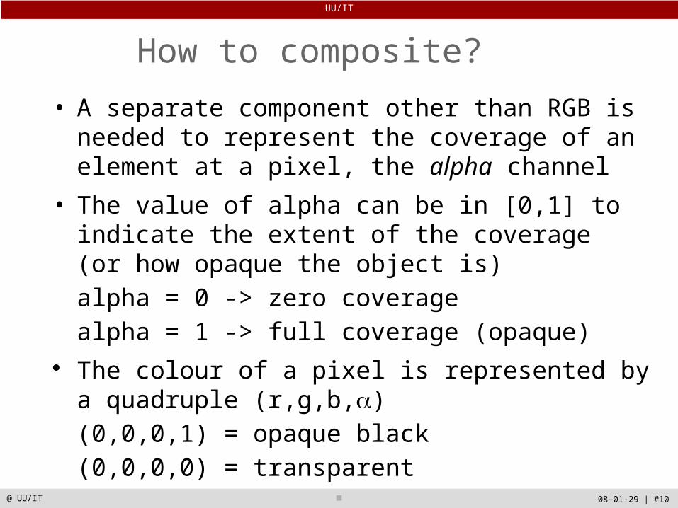
How to composite?
• A separate component other than RGB is needed to represent the coverage of an element at a pixel, the alpha channel
• The value of alpha can be in [0,1] to indicate the extent of the coverage (or how opaque the object is) alpha = 0 -> zero coveragealpha = 1 -> full coverage (opaque)
The colour of a pixel is represented by a quadruple (r,g,b,)(0,0,0,1) = opaque black (0,0,0,0) = transparent
UU/IT
08-01-29 | #11@ UU/IT
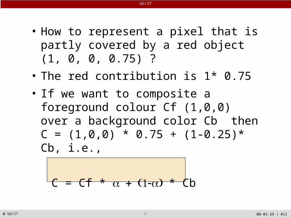
• How to represent a pixel that is partly covered by a red object (1, 0, 0, 0.75) ?
• The red contribution is 1* 0.75
• If we want to composite a foreground colour Cf (1,0,0) over a background color Cb then C = (1,0,0) * 0.75 + (1-0.25)* Cb, i.e.,
C = Cf * * Cb
UU/IT
08-01-29 | #12@ UU/IT
A problem with transparency rendering
• Objects must be drawn in the correct order.• In VTK, this is solved by sorting all objects prior to
rendering.• This makes transparency rendering quite slow

UU/IT
08-01-29 | #13@ UU/IT
Texture Mapping
UU/IT
08-01-29 | #14@ UU/IT
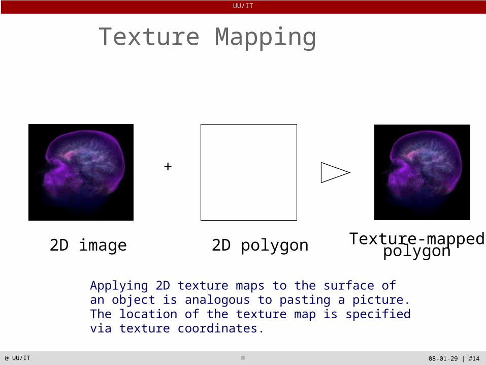
Texture Mapping
2D image 2D polygon
+
Texture-mappedpolygon
Applying 2D texture maps to the surface of an object is analogous to pasting a picture. The location of the texture map is specified via texture coordinates.
UU/IT
08-01-29 | #15@ UU/IT
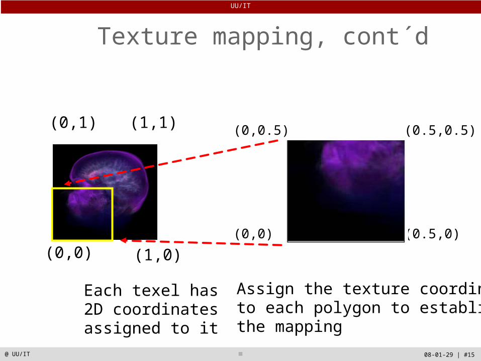
Texture mapping, cont´d
(0,0) (1,0)
(0,1) (1,1)
Each texel has 2D coordinates assigned to it
Assign the texture coordinatesto each polygon to establish the mapping
(0,0.5) (0.5,0.5)
(0,0) (0.5,0)
UU/IT
08-01-29 | #16@ UU/IT
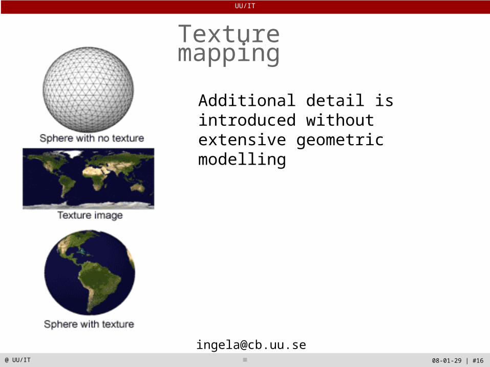
Texture mapping
Additional detail is introduced without extensive geometric modelling
UU/IT
08-01-29 | #17@ UU/IT
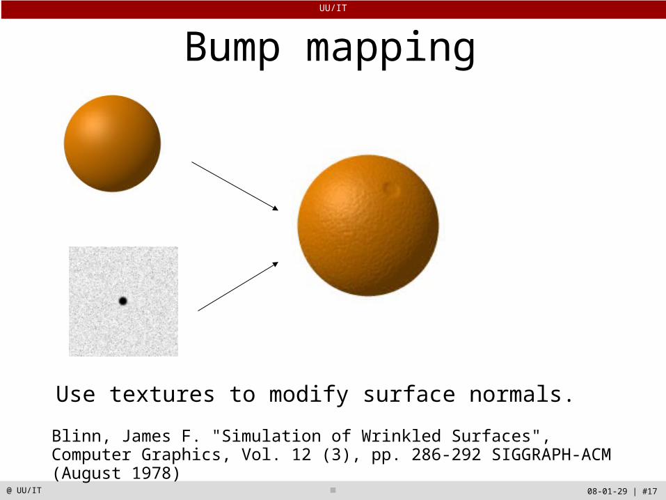
Bump mapping
Use textures to modify surface normals.
Blinn, James F. "Simulation of Wrinkled Surfaces", Computer Graphics, Vol. 12 (3), pp. 286-292 SIGGRAPH-ACM (August 1978)

UU/IT
08-01-29 | #18@ UU/IT
Alpha value in texture mapping
• By adding alpha values to make an RGBA texture map, parts of the texture becomes transparent
• Trick in computer graphics
Example:Trees have a complex modelRender a rectangular RGBA texture map for the whole forestLeaves, branches, and trunks: Gaps and open space:

UU/IT
08-01-29 | #19@ UU/IT
Digital volume images
True three-dimensional functions f(x, y, z)
Often medical data from CT, MR, PET, SPECT, …
How should these data be visualized?
N x 2D arrays = 3D array

UU/IT
08-01-29 | #20@ UU/IT
Magnetic Resonance Angiography (MRA)3D imaging of the blood vessel system
UU/IT
08-01-29 | #21@ UU/IT
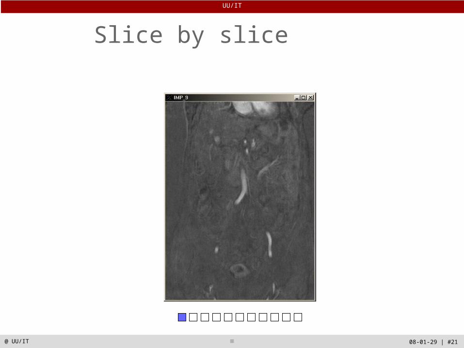
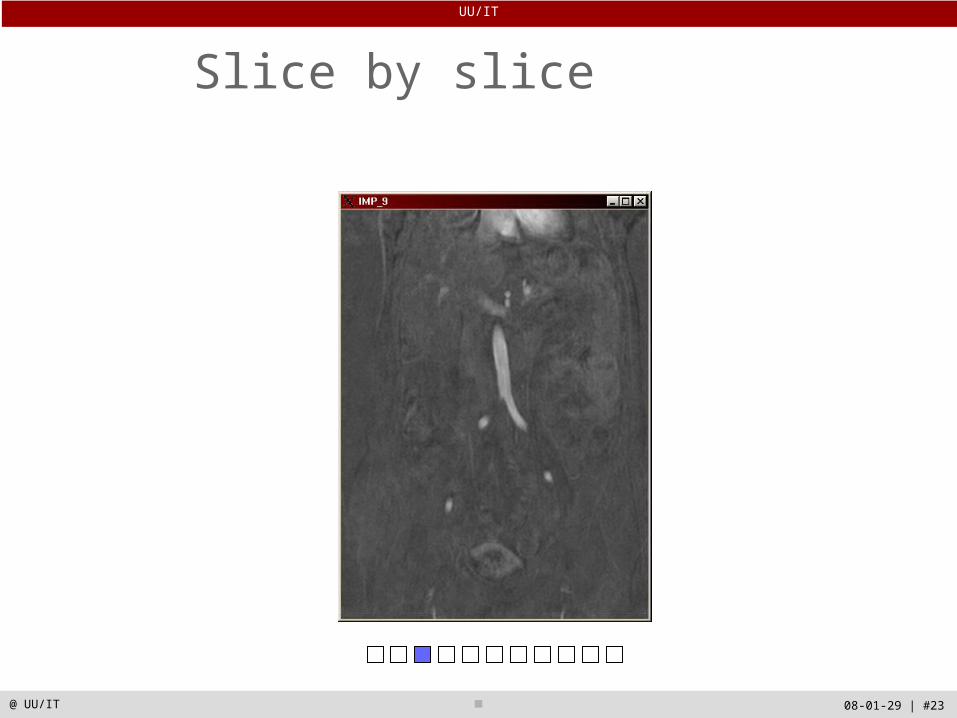
Slice by slice
UU/IT
08-01-29 | #22@ UU/IT
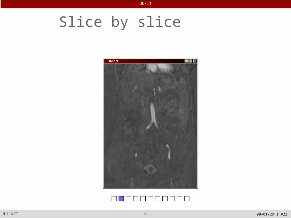
Slice by slice
UU/IT
08-01-29 | #23@ UU/IT
Slice by slice

UU/IT
08-01-29 | #24@ UU/IT
Slice by slice

UU/IT
08-01-29 | #25@ UU/IT
Slice by slice
UU/IT
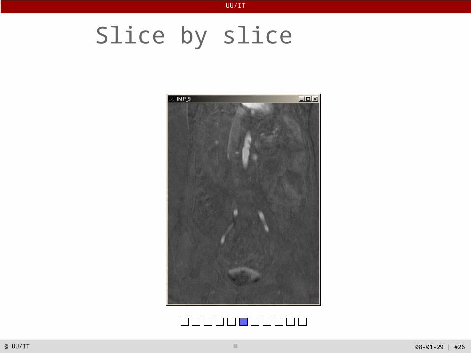
08-01-29 | #26@ UU/IT
Slice by slice

UU/IT
08-01-29 | #27@ UU/IT
Slice by slice
UU/IT
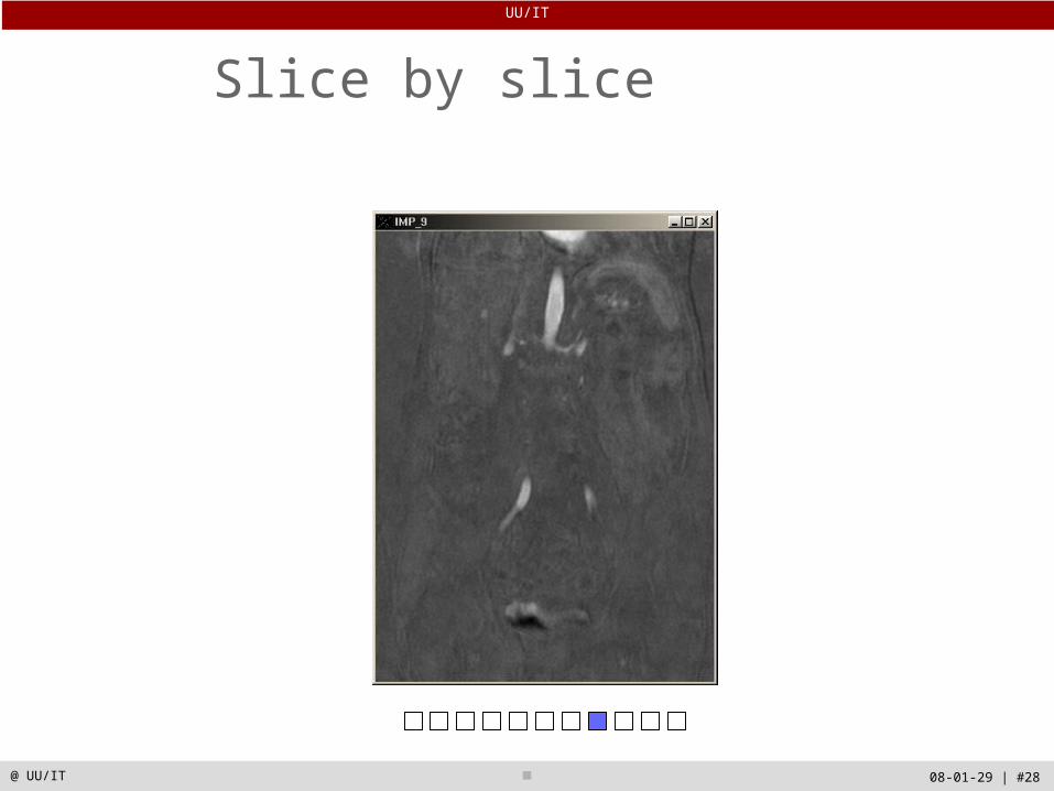
08-01-29 | #28@ UU/IT
Slice by slice
UU/IT
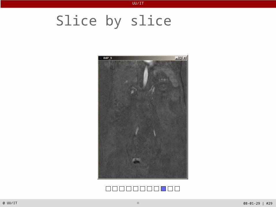
08-01-29 | #29@ UU/IT
Slice by slice
UU/IT
08-01-29 | #30@ UU/IT
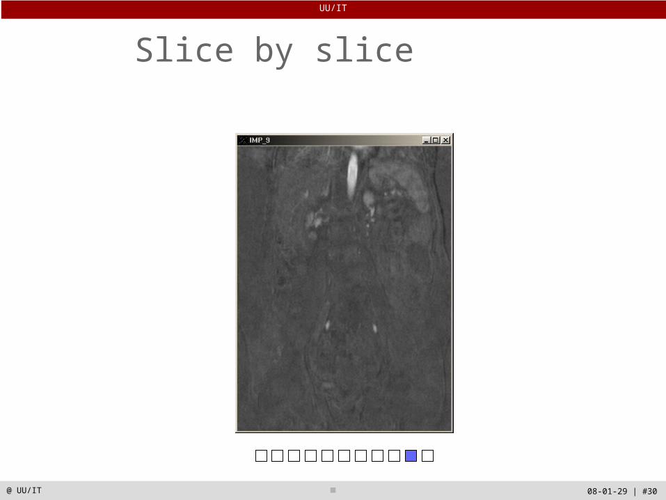
Slice by slice

UU/IT
08-01-29 | #31@ UU/IT
Slice by slice

UU/IT
08-01-29 | #32@ UU/IT
Multi-Planar Reformatting (MPR)
UU/IT
08-01-29 | #33@ UU/IT
Volume rendering approaches
• Image-order volume rendering Ray casting Front-to-back
Object-order volume rendering Splatting Footprint Back-to-front
UU/IT
08-01-29 | #34@ UU/IT
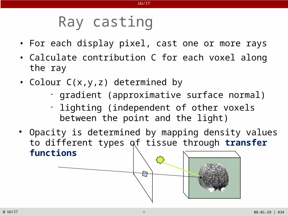
Ray casting• For each display pixel, cast one or more rays
• Calculate contribution C for each voxel along the ray
• Colour C(x,y,z) determined by gradient (approximative surface normal) lighting (independent of other voxels between the
point and the light) Opacity is determined by mapping density values to
different types of tissue through transfer functions
UU/IT
08-01-29 | #35@ UU/IT
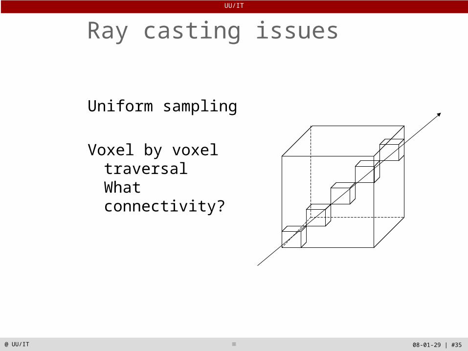
Ray casting issues
Uniform sampling
Voxel by voxel traversalWhat connectivity?
UU/IT
08-01-29 | #36@ UU/IT
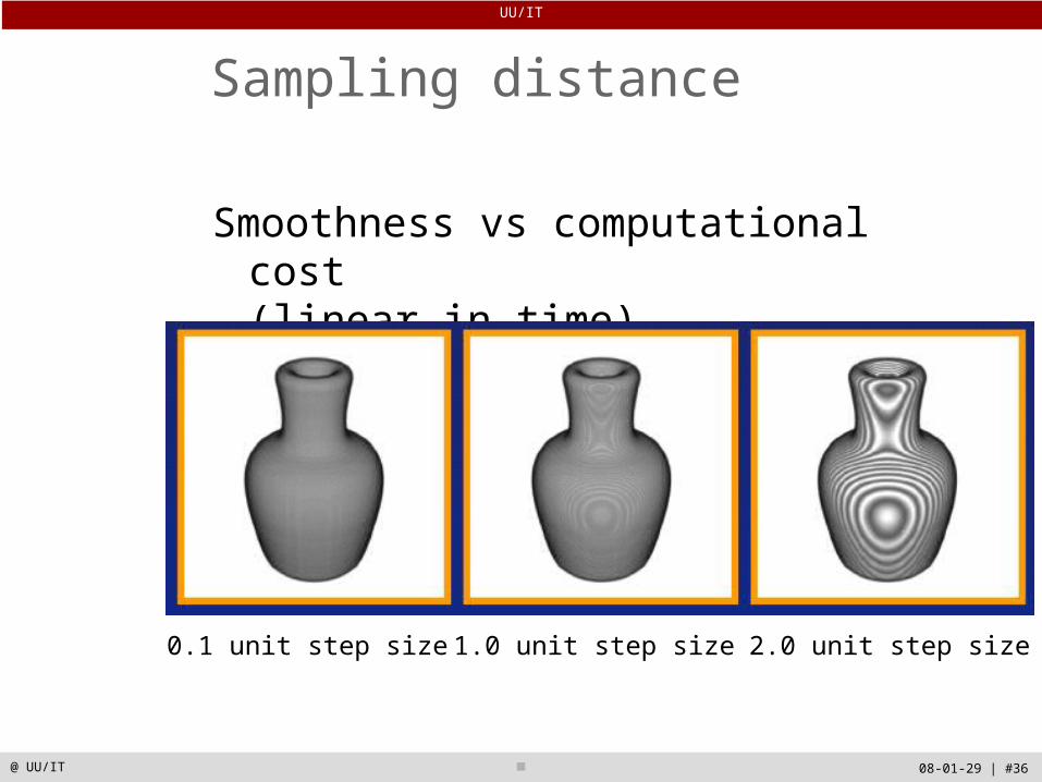
Sampling distance
0.1 unit step size 1.0 unit step size 2.0 unit step size
Smoothness vs computational cost (linear in time)
UU/IT
08-01-29 | #37@ UU/IT
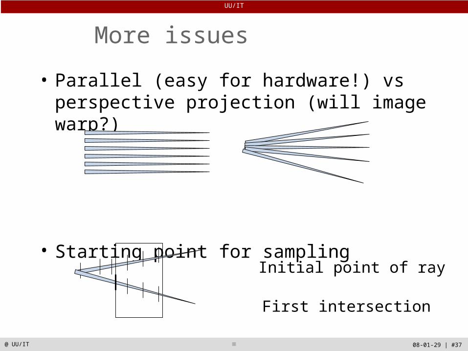
More issues
• Parallel (easy for hardware!) vs perspective projection (will image warp?)
• Starting point for sampling
Initial point of ray
First intersection
UU/IT
08-01-29 | #38@ UU/IT
Various rendering modes
Maximum intensity projection (MIP)Integral projectionDistance to a certain threshold valueDepth shadingDepth gradient shadingGrey-level gradient shadingCombined multi-modal rendering…
UU/IT
08-01-29 | #39@ UU/IT
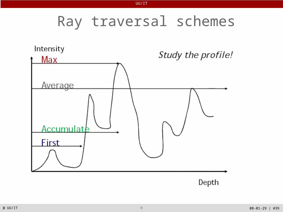
Ray traversal schemes
UU/IT
08-01-29 | #40@ UU/IT
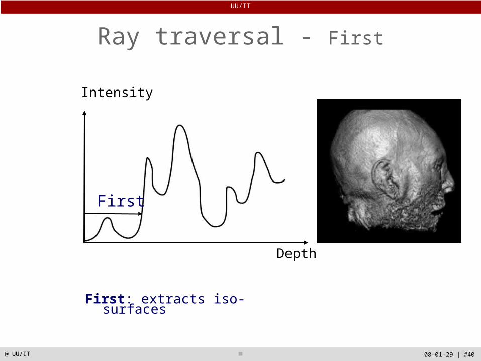
Ray traversal - First
Depth
Intensity
First
First: extracts iso-surfaces
UU/IT
08-01-29 | #41@ UU/IT
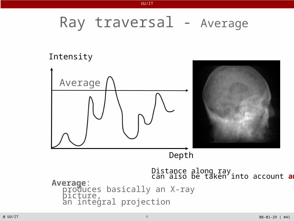
Ray traversal - Average
Depth
Intensity
Average
Average: produces basically an X-ray picture,an integral projection
Distance along ray can also be taken into account and used
UU/IT
08-01-29 | #42@ UU/IT
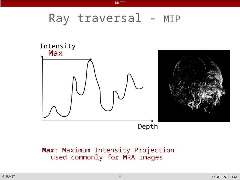
Ray traversal - MIP
Depth
IntensityMax
Max: Maximum Intensity Projectionused commonly for MRA images

UU/IT
08-01-29 | #43@ UU/IT
Ray traversal - Accumulate
Depth
Intensity
Accumulate
Accumulate opacity while compositing colors: make transparent layers visible

UU/IT
08-01-29 | #44@ UU/IT
Grey-level gradient shading
A threshold is given and the rays are cast into the volume until a voxel above the threshold is encounteredThe gradient at the points are combined with the light source to render the imageCut planes can be used to remove parts of the volume
UU/IT
08-01-29 | #45@ UU/IT
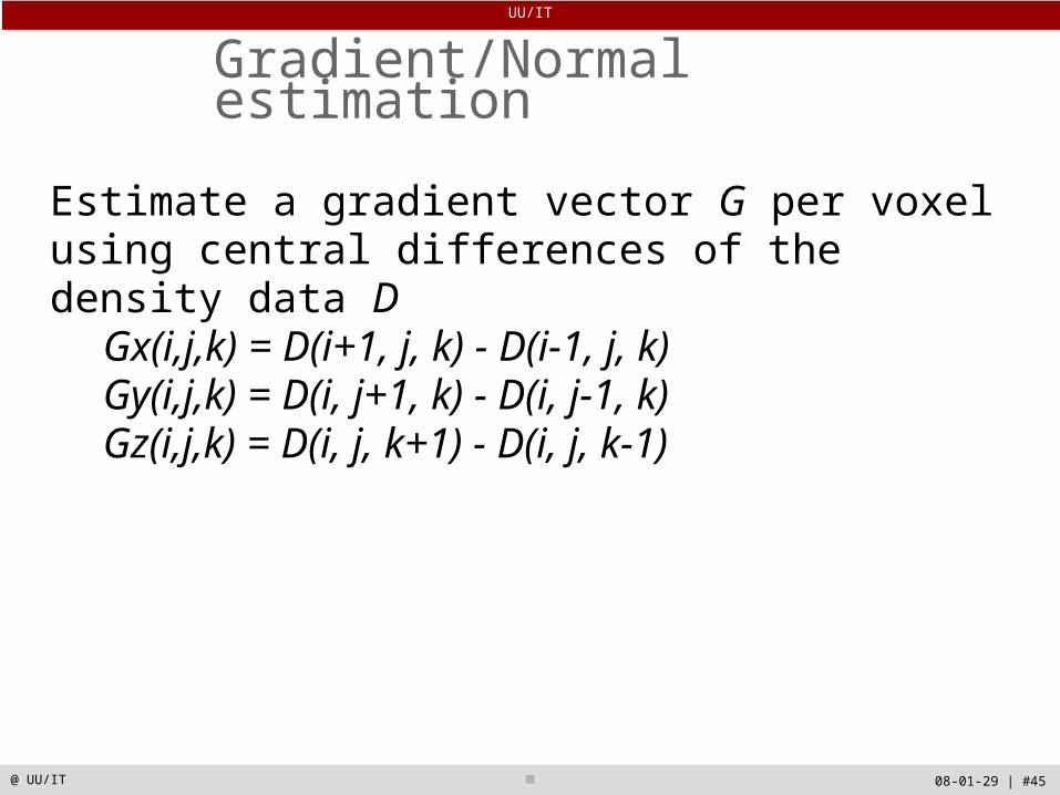
Gradient/Normal estimation
Estimate a gradient vector G per voxel using central differences of the density data D
Gx(i,j,k) = D(i+1, j, k) - D(i-1, j, k)Gy(i,j,k) = D(i, j+1, k) - D(i, j-1, k)Gz(i,j,k) = D(i, j, k+1) - D(i, j, k-1)

UU/IT
08-01-29 | #46@ UU/IT
Multi-modal rendering
MRI +
PET
Register two volumes to each otherRays are cast into the first volume For points on cut planes, values from both volumes are blended to produce a colour that enhances both modalities

UU/IT
08-01-29 | #47@ UU/IT
Splatting (feed-forward)
?
•“Splat” all voxels onto the image plane, in a back-to-front order•Trades quality for speed
UU/IT
08-01-29 | #48@ UU/IT
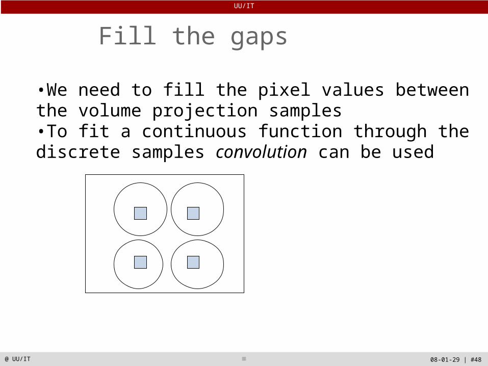
Fill the gaps
•We need to fill the pixel values between the volume projection samples •To fit a continuous function through the discrete samples convolution can be used
UU/IT
08-01-29 | #49@ UU/IT
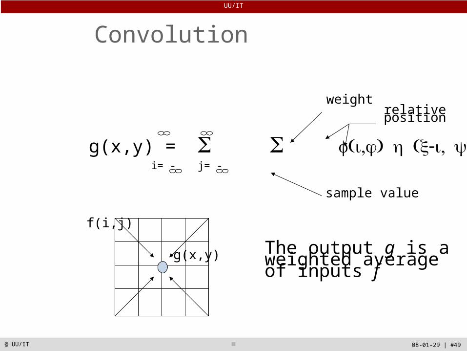
Convolution
g(x,y)
f(i,j)
The output g is a weighted average of inputs f
g(x,y) =
i= - j= -
sample value
weightrelative position
UU/IT
08-01-29 | #50@ UU/IT
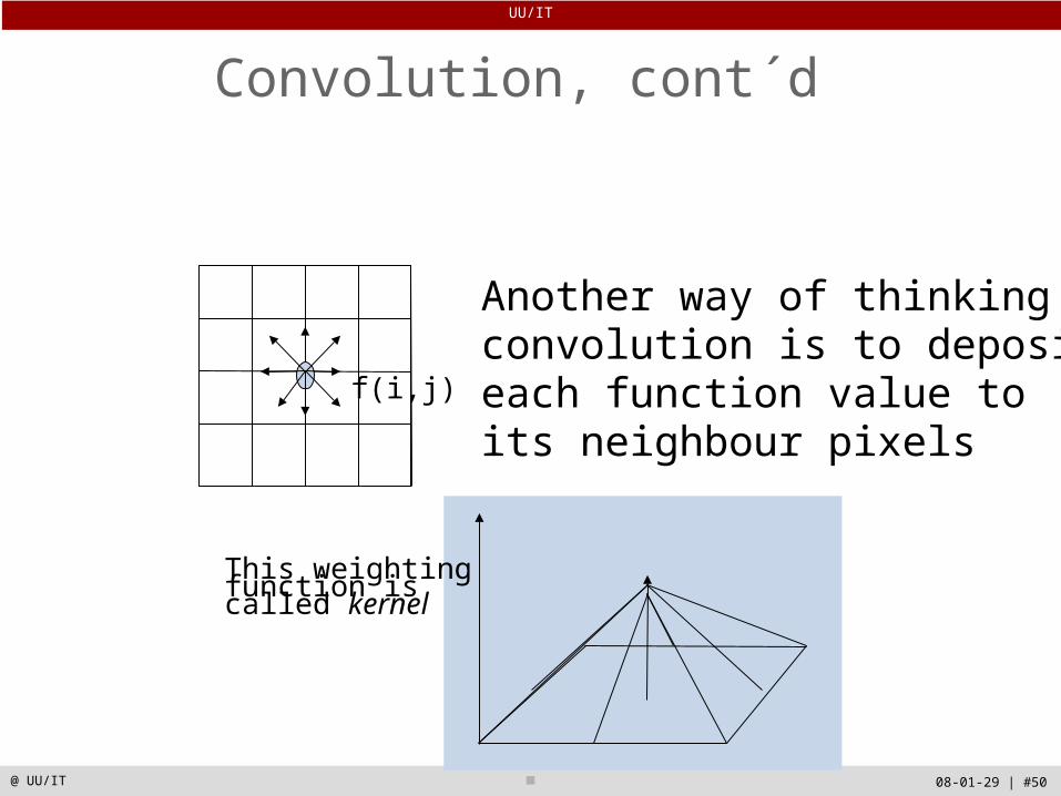
Convolution, cont´d
Another way of thinking convolution is to depositeach function value to its neighbour pixels
f(i,j)
This weightingfunction is called kernel
UU/IT
08-01-29 | #51@ UU/IT
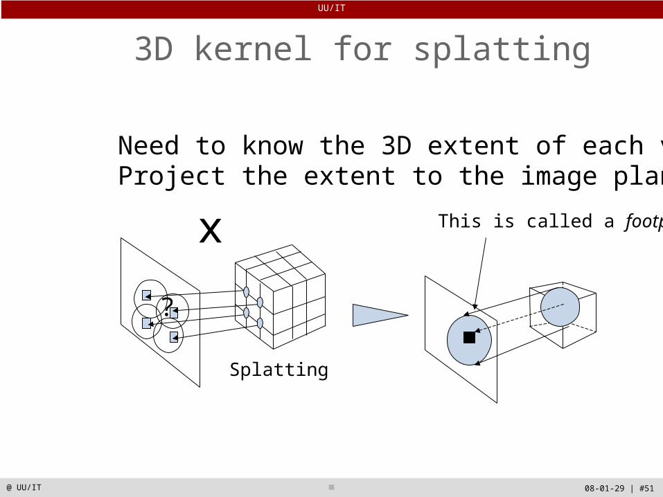
3D kernel for splatting
Need to know the 3D extent of each voxel Project the extent to the image plane
?
Splatting
x This is called a footprint
UU/IT
08-01-29 | #52@ UU/IT
Splatting
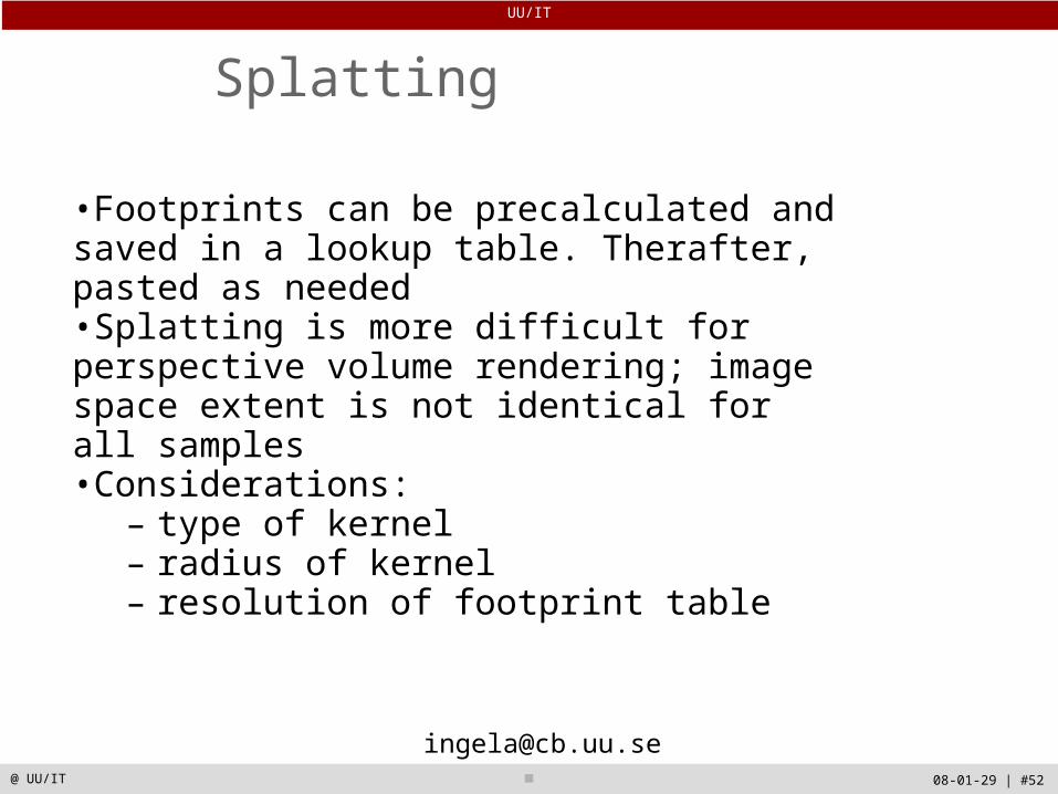
•Footprints can be precalculated and saved in a lookup table. Therafter, pasted as needed•Splatting is more difficult for perspective volume rendering; image space extent is not identical for all samples•Considerations:
– type of kernel– radius of kernel– resolution of footprint table
UU/IT
08-01-29 | #53@ UU/IT
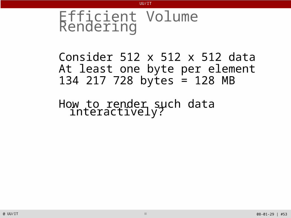
Efficient Volume Rendering
Consider 512 x 512 x 512 dataAt least one byte per element134 217 728 bytes = 128 MB
How to render such data interactively?
UU/IT
08-01-29 | #54@ UU/IT
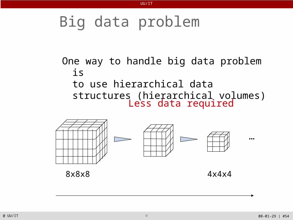
Big data problem
One way to handle big data problem is to use hierarchical data structures (hierarchical volumes)
8x8x8 4x4x4 2x2x2 …
…
Less data required
UU/IT
08-01-29 | #55@ UU/IT
Issues
Creation of hierarchical data structures
Utilization of hierarchical data structures
UU/IT
08-01-29 | #56@ UU/IT
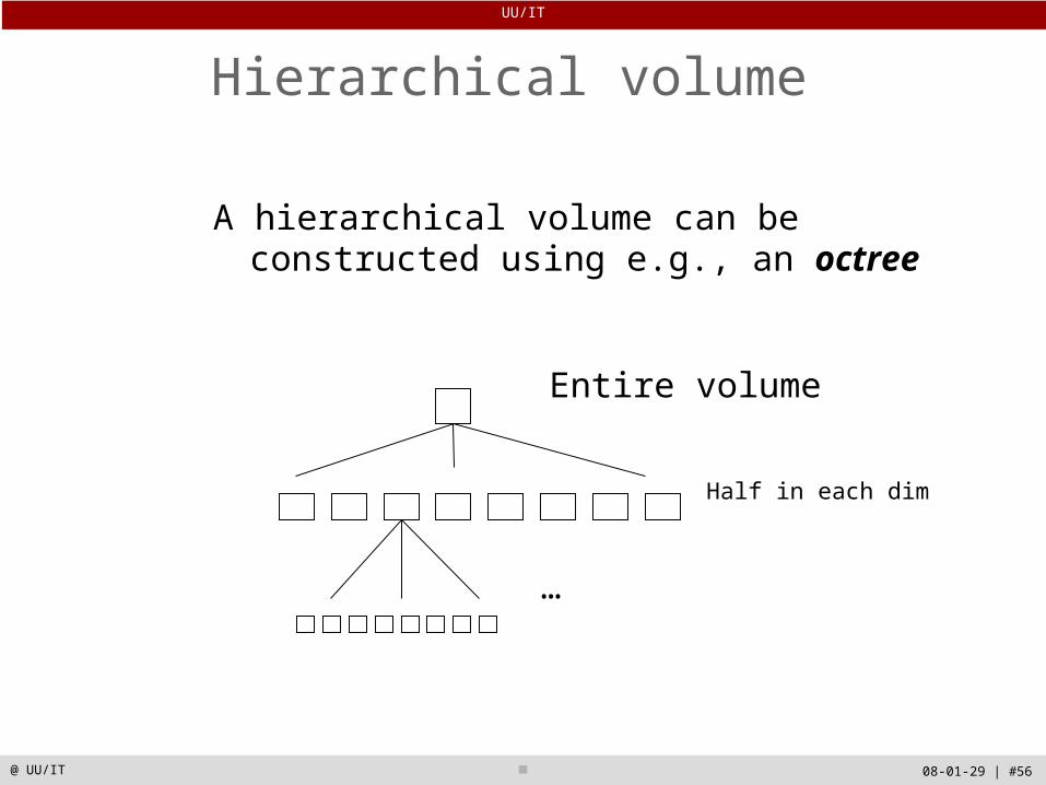
Hierarchical volume
A hierarchical volume can be constructed using e.g., an octree
…
Entire volume
Half in each dim

UU/IT
08-01-29 | #57@ UU/IT
How do we subdivide space?
We illustrate in 2D - known as quadtree
Divide space into four regions
Subdivision continues recursively until a node in the tree represents a homogeneous region of the image
Or until a specified subdivision level
UU/IT
08-01-29 | #58@ UU/IT
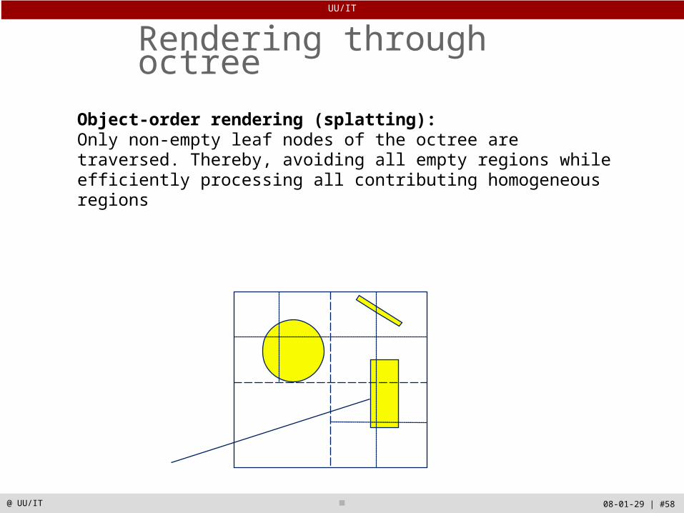
Rendering through octree
Object-order rendering (splatting):Only non-empty leaf nodes of the octree are traversed. Thereby, avoiding all empty regions while efficiently processing all contributing homogeneous regions
UU/IT
08-01-29 | #59@ UU/IT
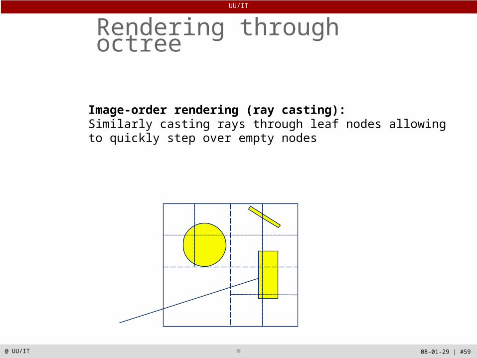
Rendering through octree
Image-order rendering (ray casting):Similarly casting rays through leaf nodes allowing to quickly step over empty nodes

UU/IT
08-01-29 | #60@ UU/IT
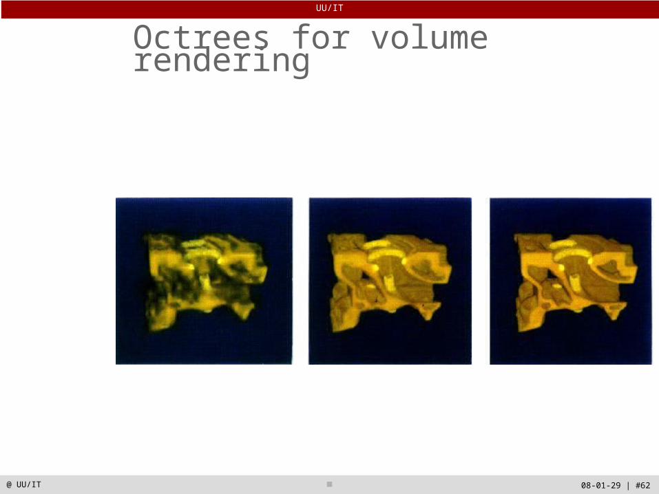
Octrees for volume rendering
Data structure: each tree node is a subvolume
Each tree node may store the mean value of the encompassed voxels
Each tree node may store an error measure: e.g., standard deviation of the voxels (root mean square to approximated value)
UU/IT
08-01-29 | #61@ UU/IT
Octrees for volume rendering
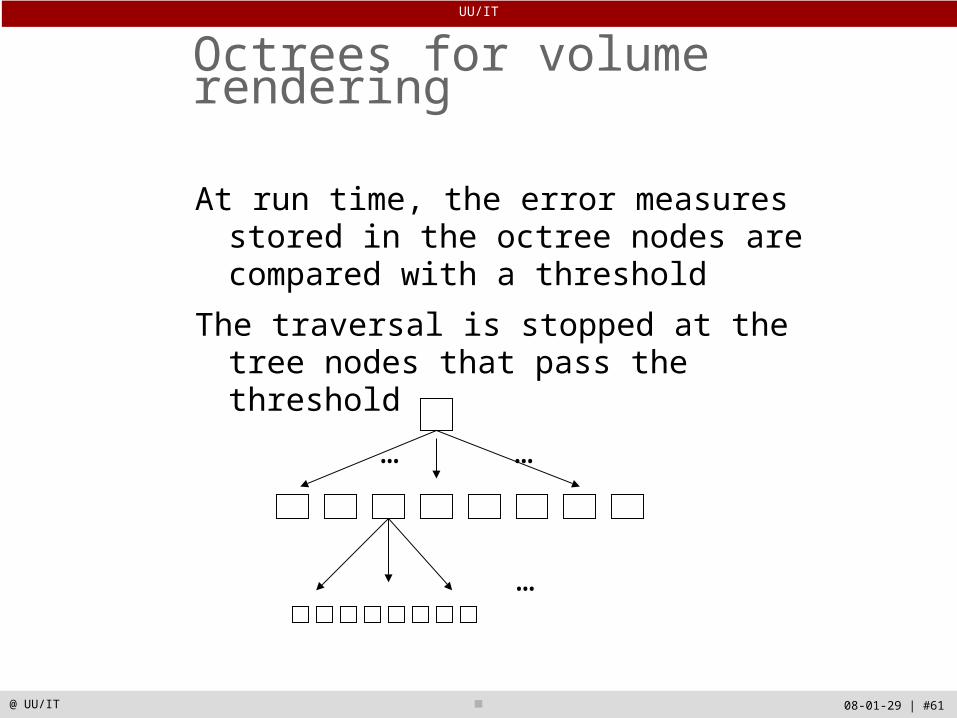
At run time, the error measures stored in the octree nodes are compared with a threshold
The traversal is stopped at the tree nodes that pass the threshold
…
… …
UU/IT
08-01-29 | #62@ UU/IT
Octrees for volume rendering

UU/IT
08-01-29 | #63@ UU/IT
Hardware accelerated volume rendering
UU/IT
08-01-29 | #64@ UU/IT
Surface versus Volume Rendering
Surface rendering+Standard computer graphics software can be used - simple +Supported by dedicated hardware - fast+A high data reduction can be achieved-Intensity information is lost-Cutting through the data is meaningless-Changes in surface definition criteria means recalculation of the data
UU/IT
08-01-29 | #65@ UU/IT
Surface versus Volume Rendering
Volume rendering+Arbitrary cuts can be made allowing the user to see inside the data+Allows for display of different aspects
MIPs semi-transparent surfaces etc.
+Rendering parameters can be changed interactively-May be slower than surface rendering

UU/IT
08-01-29 | #66@ UU/IT
Intermixing Volumes and Geometry
Department of Information Technology
- Scientific Computing
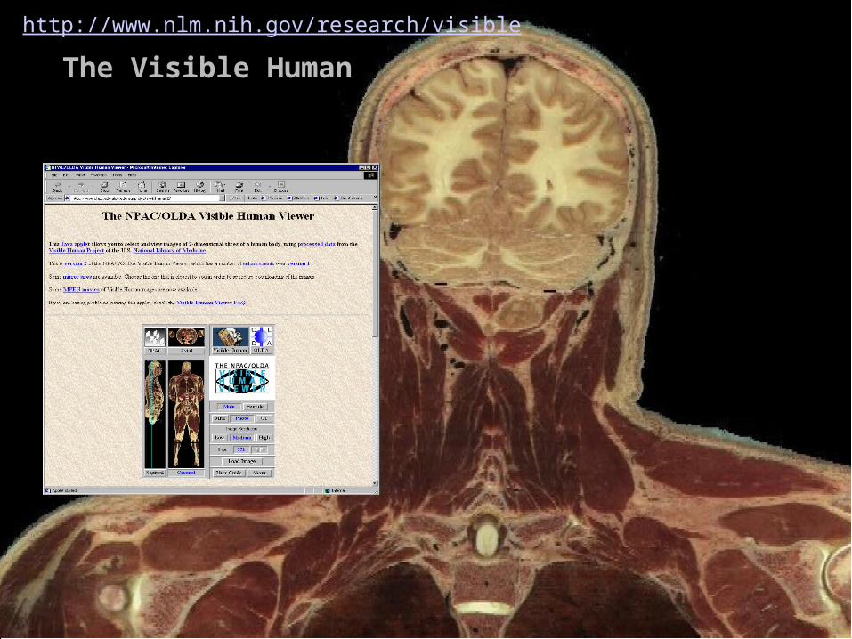
The Visible Human
http://www.nlm.nih.gov/research/visible