itec 1000 introduction to information technologies the cpu and memory
TRANSCRIPT

ITEC 1000 Introduction to Information Technologies
The CPU and Memory

ITEC 1000 Introduction to Information Technologies
Introduction
CentralProcessingUnit
In a Computer…
Memory is separate from the CPU
Data is in binary (not decimal)

ITEC 1000 Introduction to Information Technologies
System Block Diagram
ALU
CPU
Input/outputinterface
Control unit
Program counter
HighestAddress
Memory
Lowest Address

ITEC 1000 Introduction to Information Technologies
The Little Man Computer

ITEC 1000 Introduction to Information Technologies
Components of a CPU• ALU (arithmetic and logic unit)
– Performs arithmetic and logic operations– Arithmetic: add, subtract, multiply, divide, etc.– Logic: AND, OR, NOT, Shift, etc.
• Control unit– Interprets instructions– Controls the flow of information within the CPU– Works with a “program counter” (address of next
instruction)• Input/output interface
– Provides mechanism for input and output of data– Many variations possible

ITEC 1000 Introduction to Information Technologies
Registers• A register is a single storage location within the
CPU• Unlike memory, which is “outside” the CPU• Examples of registers:
– Accumulator (ACC)– Program counter (PC)– Instruction register (IR)– Memory address register (MAR)– Memory data register (MDR)– Status register
• General purpose registers (R0, R1, …)– Included on some CPUs– Used for high-speed temporary storage
ITEC 1000 Introduction to Information Technologies
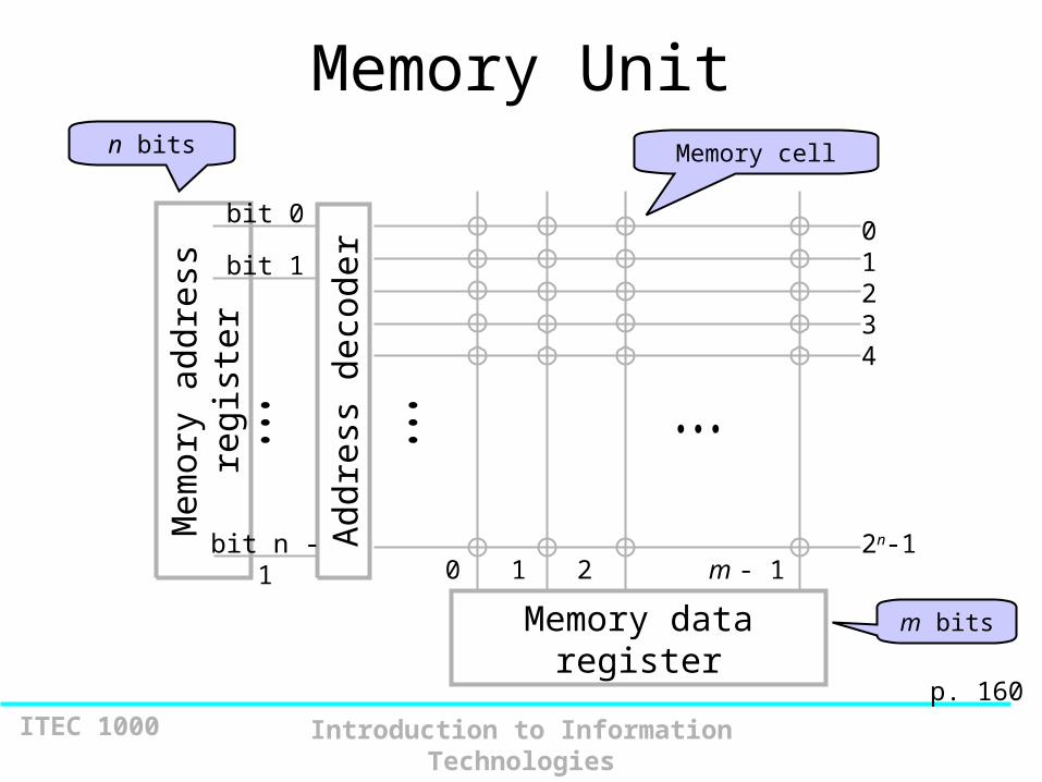
Memory Unit
Mem
ory
addr
ess
regi
ster
Add
ress
dec
oder
bit n - 1
bit 0
bit 101234
2n-1
Memory data register
Memory celln bits
m bits
0 1 2 m - 1
p. 160

ITEC 1000 Introduction to Information Technologies
MAR-MDR example

ITEC 1000 Introduction to Information Technologies
A visual analogy for memory

ITEC 1000 Introduction to Information Technologies
Memory Implementations
• RAM – random access memory– Static RAM– Dynamic RAM
• ROM – read-only memory
p. 165

ITEC 1000 Introduction to Information Technologies
RAM: Random Access Memory
• DRAM (Dynamic RAM)– Most common, cheap, less electrical power, less heat,
smaller space– Volatile: must be refreshed (recharged with power)
1000’s of times each second
• SRAM (static RAM)– Faster and more expensive than DRAM– Volatile– Small amounts are often used in cache memory for high-
speed memory access
7-11

ITEC 1000 Introduction to Information Technologies
Nonvolatile Memory
• ROM– Read-only Memory– Holds software that is not expected to change over the
life of the system such as firmware used for the system BIOS
• Flash Memory– Inexpensive nonvolatile secondary storage– Useful for nonvolatile portable computer storage,
digital cameras, tablets, smartphones– Slower rewrite time compared to RAM
7-12
ITEC 1000 Introduction to Information Technologies
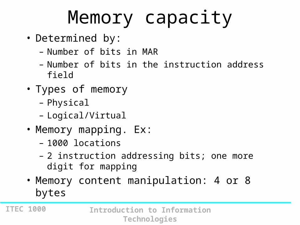
Memory capacity• Determined by:
– Number of bits in MAR
– Number of bits in the instruction address field
• Types of memory– Physical
– Logical/Virtual
• Memory mapping. Ex:– 1000 locations
– 2 instruction addressing bits; one more digit for mapping
• Memory content manipulation: 4 or 8 bytes

ITEC 1000 Introduction to Information Technologies
Memory Capacity
• 2n x m
• n address bits = 2n addresses
• m data bits; usually m = 8 (for one byte)
• m is the “width” of the data path
• Typical values:– n: 16, 17, 18, 19, 20, 21, 22, etc.– m: 8, 16, 32, 64

ITEC 1000 Introduction to Information Technologies
Question
• Q: How many bits of memory are contained in a memory unit with 512KB of memory?
A: 512 = 29, K = 210, B = byte = 8 = 23
29 x 210 x 23 = 222 = 4,194,304

ITEC 1000 Introduction to Information Technologies
Memory Maps
• The usage of memory space on a system is commonly depicted in a “memory map”
• The height of the map is determined by the number of addresses
• The width of the map is usually 8 bits
• E.g., – a system with a capacity of 216 bytes…

ITEC 1000 Introduction to Information Technologies
7 6 5 4 3 2 1 0
FFFF
000200010000
Hexadecimaladdress
Data bitposition
The “bottom” of memory
Memory Map

ITEC 1000 Introduction to Information Technologies
Use of Memory Maps• Memory maps are usually drawn to show “what is
where” on a system• The possibilities for “what”
– RAM, ROM, I/O, nothing
• The possibilities for “where”– Determined by the starting/ending addresses for each
“block” of RAM, ROM, I/O, nothing
• E.g., – a memory map for a system with a capacity of 224 bytes
with two 1 MB RAM modules residing consecutively at the bottom of memory….

ITEC 1000 Introduction to Information Technologies
FFFFFF
2000001FFFFF
1000000FFFFF
000000
224 bytes = 16 MB “capacity”
1 MB RAM
14 MB
empty
1 MB RAM
Memory Map

ITEC 1000 Introduction to Information Technologies
A dedicated register in the CPU.
Contains the address in memory of the current instruction being executed.
Incremented automatically after each instruction.
May be forced to change: eg “jump” instruction.
Usually initialize to zero when machine starts, or is reset.
Program Counter ( PC )

ITEC 1000 Introduction to Information Technologies
A dedicated register in the CPU which contains the actual current instruction.
Op Code + Address
What To Do Location of Data
Simple 16-bit example: 1101 101101100100
Instruction Register ( IR )

ITEC 1000 Introduction to Information Technologies
Memory Address Register (MAR)Contains Address in memory to find or place data.
Memory Data Register (MDR)Contains Actual Data to be placed in location given in MAR, or which has been retrieved from location given in MAR.
Memory registers

ITEC 1000 Introduction to Information Technologies
A dedicated register (or set of registers) in the CPU used for the actual manipulation of data.
Default source (or destination) register.
Usually contains results of arithmetic or logical operations.
Accumulator

ITEC 1000 Introduction to Information Technologies
Accumulator ( A or Acc )
Instruction Register ( IR )
Memory Address Register ( MAR )
Memory Data Register ( MDR )
Program Counter ( PC )
Memory
Generic CPU With Registers

ITEC 1000 Introduction to Information Technologies
Fetch-Execute Cycle• Two steps, or cycles, in the execution of
every instruction– Fetch – fetch the code for the instruction from
memory and place it in the IR (instruction register)
– Execute – execute the instruction
Fetch Executetime

ITEC 1000 Introduction to Information Technologies
The LOAD Instruction
PC MAR
MDR IR
IR[address] MAR
MDR A
PC + 1 PC
Fetch
Execute
time

ITEC 1000 Introduction to Information Technologies
The Add Instruction
PC MAR
MDR IR
IR[address] MAR
A + MDR A
PC + 1 PC
Fetch
Execute
time

ITEC 1000 Introduction to Information Technologies
Fetch-Execute Example: Load Accumulator
Assume: Simple Eight bit system.
Thirty-two memory locations (0 to 31).
“Load” instruction is 010.
Value in location 15 is ten (ie: binary 00001010)
PC contains 6 (110).
The instruction, 01001111, is in location 6.
Then ...

ITEC 1000 Introduction to Information Technologies
PC: 00110
IR: (previous)
A: (previous)
MAR: (previous)
MDR: (previous)
Location 31
15: 00001010
06: 01001111
Location 0

ITEC 1000 Introduction to Information Technologies
PC: 00110
IR: (previous)
A: (previous)
MAR: 00110
MDR: (previous)
MAR loaded with PC: PC -> MAR
Location 31
15: 00001010
06: 01001111
Location 0

ITEC 1000 Introduction to Information Technologies
PC: 00110
IR: (previous)
A: (previous)
MAR: 00110
MDR: (previous)
Memory Location 00110 Accessedand Contents Placed in MDR:
Location 31
15: 00001010
06: 01001111
Location 0

ITEC 1000 Introduction to Information Technologies
PC: 00110
IR: (previous)
A: (previous)
MAR: 00110
MDR: 01001111
Memory Location 00110 Accessedand Contents Placed in MDR:
Location 31
15: 00001010
06: 01001111
Location 0

ITEC 1000 Introduction to Information Technologies
PC: 00110
IR: 01001111
A: (previous)
MAR: 00110
MDR: 01001111
MDR copied to IR: MDR -> IR
Location 31
15: 00001010
06: 01001111
Location 0

ITEC 1000 Introduction to Information Technologies
PC: 00110
IR: 01001111
A: (previous)
MAR: 01111
MDR: 01001111
IR [ address part ] -> MAR
Location 31
15: 00001010
06: 01001111
Location 0

ITEC 1000 Introduction to Information Technologies
PC: 00110
IR: 01001111
A: (previous)
MAR: 01111
MDR: 01001111
Location in MAR (01111) Accessed
Location 31
15: 00001010
06: 01001111
Location 0

ITEC 1000 Introduction to Information Technologies
PC: 00110
IR: 01001111
A: (previous)
MAR: 01111
MDR: 00001010
Contents of 01111 loaded into MDR
Location 31
15: 00001010
06: 01001111
Location 0

ITEC 1000 Introduction to Information Technologies
PC: 00110
IR: 01001111
A: 00001010
MAR: 01111
MDR: 00001010
IR [op code] executed: MDR -> A
Location 31
15: 00001010
06: 01001111
Location 0

ITEC 1000 Introduction to Information Technologies
PC: 00111
IR: 01001111
A: 00001010
MAR: 01111
MDR: 00001010
Location 31
15: 00001010
06: 01001111
Location 0
Increment PC: PC = PC + 1

ITEC 1000 Introduction to Information Technologies
PC: 00111
IR: 01001111
A: 00001010
MAR: 01111
MDR: 00001010
Location 31
15: 00001010
06: 01001111
Location 0
Finished

ITEC 1000 Introduction to Information Technologies
Now:
Assume: Value in location 7 is 10110010.
“Add” instruction is 101.
Value in location 18 is seventy-one
(i.e.: binary 01000111)
Everything else is as we left it!
Then ...

ITEC 1000 Introduction to Information Technologies
PC: 00111
IR: 01001111
A: 00001010
MAR: 00111
MDR: 00001010
PC -> MAR
Location 31
18: 01000111
15: 00001010
07: 10110010
06: 01001111
Location 0

ITEC 1000 Introduction to Information Technologies
PC: 00111
IR: 01001111
A: 00001010
MAR: 00111
MDR: 00001010
MAR Accesses Location 00111
Location 31
18: 01000111
15: 00001010
07: 10110010
06: 01001111
Location 0

ITEC 1000 Introduction to Information Technologies
PC: 00111
IR: 01001111
A: 00001010
MAR: 00111
MDR: 10110010
Contents of 00111 -> MDR
Location 31
18: 01000111
15: 00001010
07: 10110010
06: 01001111
Location 0

ITEC 1000 Introduction to Information Technologies
PC: 00111
IR: 10110010
A: 00001010
MAR: 00111
MDR: 10110010
MDR -> IR
Location 31
18: 01000111
15: 00001010
07: 10110010
06: 01001111
Location 0

ITEC 1000 Introduction to Information Technologies
PC: 00111
IR: 10110010
A: 00001010
MAR: 10010
MDR: 10110010
IR [address] -> MAR
Location 31
18: 01000111
15: 00001010
07: 10110010
06: 01001111
Location 0

ITEC 1000 Introduction to Information Technologies
PC: 00111
IR: 10110010
A: 00001010
MAR: 10010
MDR: 10110010
Location 10010 [MAR] Accessed
Location 31
18: 01000111
15: 00001010
07: 10110010
06: 01001111
Location 0

ITEC 1000 Introduction to Information Technologies
PC: 00111
IR: 10110010
A: 00001010
MAR: 10010
MDR: 01000111
Contents of [10010] -> MDR
Location 31
18: 01000111
15: 00001010
07: 10110010
06: 01001111
Location 0

ITEC 1000 Introduction to Information Technologies
PC: 00111
IR: 10110010
A: 01010001
MAR: 10010
MDR: 01000111
IR [opcode] executed: A = A + MDR
Location 31
18: 01000111
15: 00001010
07: 10110010
06: 01001111
Location 0

ITEC 1000 Introduction to Information Technologies
PC: 01000
IR: 01001111
A: 00001010
MAR: 01111
MDR: 00001010
Increment PC: PC = PC + 1
Location 31
18: 01000111
15: 00001010
08: 07: 10110010
06: 01001111
Location 0

ITEC 1000 Introduction to Information Technologies
To Continue:
If the next instruction were to load the Accumulator contents into an area of memory reserved for screen output (for example), then the number “81” should appear on the screen.
The process continues in the same fashion, more or less, until a stop or halt instruction is encountered.

ITEC 1000 Introduction to Information Technologies
Buses
• Definition: a collection of electrical conductors (eg: wires, traces) with a common purpose
• Each wire or trace is called a line
• Typically, buses carry information from one place to another
From our first lecture…Ed: k c

ITEC 1000 Introduction to Information Technologies
Ports
CPU
RAM
Diskcontroller
Graphicscard
Soundcard
Networkcard
Printer
Mouse
Keyboard
ModemMonitor
Speakers
bus
Computer

ITEC 1000 Introduction to Information Technologies
Bus• The physical connection that makes it possible to
transfer data from one location in the computer system to another
• Group of electrical or optical conductors for carrying signals from one location to another
– Wires or conductors printed on a circuit board– Line: each conductor in the bus
• 4 kinds of signals1. Data2. Addressing3. Control signals4. Power (sometimes)
7-53

ITEC 1000 Introduction to Information Technologies
Bus Characteristics• Number of separate wires or conductors
• Data width in bits carried simultaneously
• Addressing capacity
• Lines on the bus are for a single type of signal or shared
• Throughput – data transfer rate in bits per second
• Distance between two endpoints
• Number and type of attachments supported
• Type of control required
• Defined purpose
• Features and capabilities
7-54

ITEC 1000 Introduction to Information Technologies
Types of Buses (1 of 3)
• Point-to-pointSerialport
Modem
Controlunit ALU

ITEC 1000 Introduction to Information Technologies
Types of Buses (2 of 3)
• Multipoint
Computer
CPU
Disk controller
Computer
Computer Computer
Memory
Video controller

ITEC 1000 Introduction to Information Technologies
Types of Buses (3 of 3)
• Daisy chainDevice controller
Device
Device
Device
Terminator

ITEC 1000 Introduction to Information Technologies
Buses Inside a Computer
Data busAddress busControl bus
MemoryI/O Module
I/O Device
CPU
Motherboard• Many
configurations possible

ITEC 1000 Introduction to Information Technologies
Bus Categorizations• Parallel vs. serial buses
• Direction of transmission– Simplex – unidirectional
– Half duplex – bidirectional, one direction at a time
– Full duplex – bidirectional simultaneously
• Method of interconnection– Point-to-point – single source to single destination
• Cables – point-to-point buses that connect to an external device
– Multipoint bus – also broadcast bus or multidrop bus• Connect multiple points to one another
7-59

ITEC 1000 Introduction to Information Technologies
Parallel vs. Serial Buses• Parallel
– High throughput because all bits of a word are transmitted simultaneously
– Expensive and require a lot of space
– Subject to radio-generated electrical interference, which limits their speed and length
– Generally used for short distances such as CPU buses and on computer motherboards
• Serial– 1 bit transmitted at a time
– Single data line pair and a few control lines
– For many applications, throughput is higher than for parallel because of the lack of electrical interference
7-60

ITEC 1000 Introduction to Information Technologies
Data Bus
• Carries data between the CPU and memory or I/O devices
• Bi-directional– Data transferred “out of” the CPU for write operations
– Data transferred “into” the CPU for read operations
• Typical sizes: 8, 16, 32, 64 lines• Signal names:
– D0, D1, D2, D3, etc.

ITEC 1000 Introduction to Information Technologies
Address Bus
• Carries an address from the CPU to Memory or I/O devices
• Unidirectional– The address is always supplied by the CPU
(There is one exception to this, which we’ll discuss later.)
• Typical sizes: 16, 20, 24 lines• Signal names:
– A0, A1, A2, A3, etc.

ITEC 1000 Introduction to Information Technologies
Control Bus• Collection of signals for coordinating CPU
activities• Each signal has a unique purpose• Typical sizes: 10-20 lines• Signals are output, input, or bi-directional• Typical signals
– /RD (read)– /WR (write– CLK (clock)– /IRQ (interrupt request)– etc.

ITEC 1000 Introduction to Information Technologies
Figure 7.11 Alternative bus notations

ITEC 1000 Introduction to Information Technologies
Classification of Instructions
• Data Movement (load, store)– Most common, greatest flexibility– Involve memory and registers– What’s this size of a word ? 16? 32? 64 bits?
• Arithmetic– Operators + - / * ^– Integers and floating point
• Boolean Logic – Often includes at least AND, XOR, and NOT
• Single operand manipulation instructions– Negating, decrementing, incrementing, set to 0
7-65

ITEC 1000 Introduction to Information Technologies
More Instruction Classifications
• Bit manipulation instructions– Flags to test for conditions
• Shift and rotate
• Program control
• Stack instructions
• Multiple data instructions
• I/O and machine control
7-66

ITEC 1000 Introduction to Information Technologies
Register Shifts and Rotates
7-67

ITEC 1000 Introduction to Information Technologies
Program Control Instructions
• Program control– Jump and branch
– Subroutine call and return
7-68

ITEC 1000 Introduction to Information Technologies
Stack Instructions• Stack instructions
– LIFO method for organizing information – Items removed in the reverse order from how they are added
Push
Pop
7-69

ITEC 1000 Introduction to Information Technologies
Cache Memory• Blocks: between 8 and 64 bytes • Cache Line
– Unit of transfer between storage and cache memory
• Tags: pointer to location in main memory• Cache controller
– Hardware that checks tags to determine if in cache
• Hit Ratio: ratio of hits out of total requests

ITEC 1000 Introduction to Information Technologies
Step-by-Step Use of Cache

ITEC 1000 Introduction to Information Technologies
Step-by-Step Use of Cache

ITEC 1000 Introduction to Information TechnologiesCopyright 2013 John Wiley & Sons, Inc.
Traditional Modern ArchitecturesProblems with early CPU Architectures and solutions:• Large number of specialized instructions were rarely used
but added hardware complexity and slowed down other instructions
• Slow data memory accesses could be reduced by increasing the number of general purpose registers
• Using general registers to hold addresses could reduce the number of addressing modes and simplify architecture design
• Fixed-length, fixed-format instruction words would allow instructions to be fetched and decoded independently and in parallel
8-73

ITEC 1000 Introduction to Information Technologies
Performance Advantages• Hit ratios of 90% and above are common• 50%+ improved execution speed• Locality of reference is why caching works
– Most memory references confined to small region of memory at any given time
– Well-written program in small loop, procedure, or function
– Data likely in array
– Variables stored together

ITEC 1000 Introduction to Information Technologies
Multiprocessing
• Reasons– Increase the processing power of a system– Parallel processing through threads: independent
segments of a program that can be executed concurrently
• Multiprocessor system– Tightly coupled– Multicore processors—when CPUs are on a single
integrated circuit
8-75

ITEC 1000 Introduction to Information Technologies
Multiprocessor Systems
• Identical access to programs, data, shared memory, I/O, etc.
• Easily extends multi-tasking and redundant program execution
• Each CPU in a Processor is called a Core
• Two ways to configure– Master-slave multiprocessing– Symmetrical multiprocessing (SMP)
8-76

ITEC 1000 Introduction to Information Technologies
Typical Multiprocessing System Configuration
8-77

ITEC 1000 Introduction to Information Technologies
Master-Slave Multiprocessing
• Master CPU– Manages the system– Controls all resources and scheduling– Assigns tasks to slave CPUs
• Advantages– Simplicity– Protection of system and data
• Disadvantages– Master CPU becomes a bottleneck– Reliability issues—if master CPU fails entire system fails
8-78

ITEC 1000 Introduction to Information Technologies
Symmetrical Multiprocessing• Each CPU has equal access to resources• Each CPU determines what to run using a standard
algorithm• Disadvantages
– Resource conflicts: memory, I/O, etc.– Complex implementation
• Advantages– High reliability– Fault tolerant support is straightforward– Balanced workload
8-79

ITEC 1000 Introduction to Information Technologies
Multiple, Parallel Execution Units
• Different instructions have different numbers of steps in their cycle
• Differences in each step
• Each execution unit is optimized for one general type of instruction
• Multiple execution units permit simultaneous execution of several instructions
Copyright 2013 John Wiley & Sons, Inc. 8-80

ITEC 1000 Introduction to Information TechnologiesCopyright 2013 John Wiley & Sons, Inc.
Superscalar Processing
• Process more than one instruction per clock cycle
• Separate fetch and execute cycles as much as possible
• Buffers for fetch and decode phases
• Parallel execution units
8-81

ITEC 1000 Introduction to Information TechnologiesCopyright 2013 John Wiley & Sons, Inc.
Scalar vs. Superscalar Processing
8-82
http://www.intel.com/content/www/us/en/architecture-and-technology/hyper-threading/hyper-threading-technology-video.html

ITEC 1000 Introduction to Information Technologies
• Intel Core i7– 2-4 Cores– 2.2 – 4.0 GHz– http://www.intel.com/content/www/us/en/proce
ssors/core/core-i7-processor.html