itc 220 wayside transceiver - calamphelp.calamp.com/files/references/manuals/m_itcwayside.pdfitc 220...
TRANSCRIPT

ITC 220 Wayside Transceiver HIGH PERFORMANCE WIRELESS FOR RAILROAD PTC
Installation Guide PN 133981 Rev. A Revised July 2012

REVISION HISTORY
REV DATE REVISION DETAILS
A July 2012 Initial release. Part number 133981.
ITC 220 Wayside Transceiver Installation Guide PN 133981 Rev. A | Page i
Important Notice Because of the nature of wireless communication, transmission and reception of data can never be guaranteed. Data may be delayed, corrupted (i.e. have errors), or be totally lost. Significant delays or losses of data are rare when wireless devices such as CalAmp provides are used in a normal manner with a well-constructed network. These products should not be used in situations where failure to transmit or receive data could result in damage of any kind to the user or any other party, including but not limited to personal injury or death, or loss of property. CalAmp accepts no responsibility for damages of any kind resulting from delays or errors in data transmitted or received using the ITC 220 Base Station, Locomotive, or Wayside Transceiver, or for failure to transmit or receive such data.
Copyright Notice © Copyright 2012 CalAmp. All rights reserved.
Products offered may contain software proprietary to CalAmp or other parties. The offer of supply of these products and services does not include or infer any transfer of ownership. No part of the documentation or information supplied may be divulged to any third party without the express written consent of CalAmp.
CalAmp reserves the right to update its products, software, or documentation without obligation to notify any individual or entity. Product updates may result in differences between the information provided in this manual and the product shipped. For access to the most current product documentation and application notes, visit www.calamp.com.
RF Exposure Compliance Requirements The ITC 220 Base Station, Locomotive, and Wayside Transceivers are intended for use in the railroad industry as Interoperable Train Control (ITC) Radio (ITCR), which is an important component of Positive Train Control (PTC). The ITC 220 Base station, Locomotive, and Wayside Transceiver units must be professionally installed and must ensure a minimum separation distance between the antenna or radiating structure and any person. Refer to Table 1 and 2 on pages 3 and 4 of the RF Energy Exposure Guide for ITC 220 Base Station, Locomotive, and Wayside Transceivers Installed in Vehicles or at Fixed Sites for
recommended minimum lateral distance, as applicable for the antenna application, type of antenna, and transmitting power.
Radio Transceiver Model Antenna application Section and applicable table
ITC 220 Base Station Transceiver Fixed installation Section 6 Fixed Installations; Table 2 on Page 5
ITC 220 Locomotive Transceiver Mobile installation Section 4 Mobile Installations; Table 1 on Page 3
ITC 220 Wayside Transceiver Fixed installation Section 6 Fixed Installations; Table 2 on Page 5
ITC 220 Wayside Transceiver Mobile installation Section 4 Mobile Installations; Table 1 on Page 3
It is the responsibility of the user to guarantee compliance with the FCC MPE regulations when operating this device in a way other than described above. The installer of this equipment must ensure the antenna is located or pointed such that it does not emit an RF field in excess of Health Canada limits for the general population.
ITC 220 Base Station, Locomotive, and Wayside Transceivers use a low power radio frequency transmitter. The concentrated energy from an antenna may pose a health hazard. People should not be in front of the antenna when the transmitter is operating.
Recommended safety guidelines for the human exposure to radio frequency electromagnetic energy are contained in the Canadian Safety Code 6 (available from Health Canada), the Federal Communications Commission (FCC) Bulletin 65 and the Council of the European Union’s Recommendation of 12 July 1999 on the limitation of exposure of the general public to electromagnetic fields (0 Hz to 300 GHz) (1999/519/EC).
Any changes or modifications not expressly approved by the party responsible for compliance (in the country where used) could void the user’s authority to operate the equipment.

ITC 220 Wayside Transceiver Installation Guide PN 133981 Rev. A | Page ii
TABLE OF CONTENTS
1 Overview ......................................................................................................................................... 1
1.1 General Description ............................................................................................................................................... 1
1.2 Operational Characteristics .................................................................................................................................... 2
1.3 Physical Description ............................................................................................................................................... 3
1.3.1 Dimensions ................................................................................................................................................... 3
1.3.2 Connections .................................................................................................................................................. 5
1.4 Related Documents ................................................................................................................................................ 6
2 Follow Established Safety Guidelines ............................................................................................. 7
2.1 Electrical Safety ...................................................................................................................................................... 7
3 Important Information for the User ............................................................................................... 7
3.1 Limiting RF Exposure .............................................................................................................................................. 7
3.2 Fixed Antenna Guidelines ...................................................................................................................................... 8
3.3 RF Interference to Residential Receivers ............................................................................................................... 8
3.4 Equipment Modifications ....................................................................................................................................... 8
4 Wayside Transmitter Operation ..................................................................................................... 9
4.1 Wayside Transceiver Channelization and Frequency Range .................................................................................. 9
4.2 Wayside Channel Restrictions ................................................................................................................................ 9
4.3 Wayside-Radiated Power Limits ............................................................................................................................ 9
5 Routine Maintenance ................................................................................................................... 10
6 Installation .................................................................................................................................... 11
6.1 Required Equipment ............................................................................................................................................ 12
6.2 Unpack and Inspect the Unit ................................................................................................................................ 13
6.3 Confirm SD Memory Card (CIM) is Installed and Seated ..................................................................................... 13
6.4 Mount the Wayside Transceiver .......................................................................................................................... 13
6.5 Ground the Radio Transceiver ............................................................................................................................. 15
6.6 Connect Current-Limiting Circuit Protection ........................................................................................................ 16
6.7 Connect RF Antenna ............................................................................................................................................ 16
6.7.1 Antenna Planning ........................................................................................................................................ 16
6.7.2 Connect Antenna Cable for the Narrowband RF Antenna .......................................................................... 16
6.8 Connect the GPS Antenna .................................................................................................................................... 17
6.9 Connect the Ethernet Cable ................................................................................................................................. 17
6.10 Connect the Power Cable ..................................................................................................................................... 18
ITC 220 Wayside Transceiver Installation Guide PN 133981 Rev. A | Page iii
6.11 Power On the Transceiver .................................................................................................................................... 19
6.11.1 LED Diagnostics ........................................................................................................................................... 19
6.11.2 Review the Power On Self-Test (POST) Results .......................................................................................... 20
6.11.3 Determine and Verify or Set GPS Coordinates ........................................................................................... 21
6.11.4 Verify the Transceiver is Commissioned ..................................................................................................... 21
6.11.5 Verify LAN Ethernet Port is Operational ..................................................................................................... 22
7 Troubleshooting ............................................................................................................................ 23
7.1 Guidelines for Troubleshooting Common Problems ............................................................................................ 23
7.2 Power Problems ................................................................................................................................................... 24
7.3 SD Memory Card Problems .................................................................................................................................. 24
7.4 Antenna Problems................................................................................................................................................ 25
7.5 Transmission Problems ........................................................................................................................................ 26
7.6 Reception Problems ............................................................................................................................................. 27
7.7 Ethernet Connectivity Problems .......................................................................................................................... 27
7.8 RF Link Problems .................................................................................................................................................. 28
APPENDIX A — Abbreviations and Definitions ................................................................................... 30
APPENDIX B — GPS Satellite Constellation Overview and Antenna Planning Considerations .......... 32
B.1 GPS Satellite Constellation Overview ....................................................................................................................... 32
B.2 GPS Antenna Planning Considerations ..................................................................................................................... 33
B.2.1 Minimize Potential of GPS Antenna Issues ........................................................................................................ 34
B.2.2 Determine GPS Coordinates .............................................................................................................................. 34
APPENDIX C — Configure the Computer Ethernet Ports to Communicate with the Transceiver ..... 37
C.1 To Configure the Computer Ethernet 1 Interface for Communication with the Transceiver MAINT Port ............... 38
C.2 To Configure the Computer Ethernet 2 Interface for Communication with the Transceiver LAN Port .................... 41
C.3 Creating an XtermW Connection Profile ................................................................................................................... 43
APPENDIX D — Sample POST Results from a Properly Functioning Wayside Transceiver ................ 45
APPENDIX E — Command Security .................................................................................................... 48
E.1 Log On to the Transceiver ......................................................................................................................................... 48
E.2 Log Off From the Transceiver .................................................................................................................................... 49
E.3 Change Your Transceiver Password .......................................................................................................................... 49
E.3.1 Forget Your Password? ...................................................................................................................................... 50
APPENDIX F — Commonly Used Diagnostic Commands ................................................................... 51
INICHECK ..................................................................................................................................................................... 51
LINKSTAT ..................................................................................................................................................................... 51
REV ............................................................................................................................................................................. 52

ITC 220 Wayside Transceiver Installation Guide PN 133981 Rev. A | Page iv
STAT,RF ....................................................................................................................................................................... 52
STAT,HRX ..................................................................................................................................................................... 53
APPENDIX G — Transceiver Test and Adjustment Procedures .......................................................... 54
G.1 Required Equipment ................................................................................................................................................. 54
G.2 Put a Trace on a Feature ........................................................................................................................................... 54
APPENDIX H — Managing Software Application Images.................................................................... 57
H.1 Determining Software Image Status......................................................................................................................... 57
H.2 Updating Software Images ....................................................................................................................................... 59
H.2.1 Updating Transceiver Software Using the Command Line ................................................................................ 59
H.3 Rolling Back an Image ............................................................................................................................................... 63
H.3.1 How Automatic Rollback Occurs ....................................................................................................................... 63
H.3.2 Determining If Automatic Rollback Occurred ................................................................................................... 63
H.3.3 Rolling Back an Image via the Command Line: APPS ........................................................................................ 64
H.4 Maintaining Multiple Software Images in the Transceiver....................................................................................... 65
H.4.1 Managing Images Via the Command Line: APPS ............................................................................................... 65
H.4.2 System Events On Installed Software Images ................................................................................................... 66

ITC 220 Wayside Transceiver Installation Guide PN 133981 Rev. A | Page 1
1 OVERVIEW
This ITC 220 Wayside Transceiver Installation Guide provides important electrical safety and radio-frequency
compliance information, operation and routine maintenance instructions, and installation and troubleshooting
procedures for CalAmp ITC 220 Wayside Transceivers.
This manual provides essential information for personnel who perform the following on the Wayside Transceiver:
Operation and routine maintenance (Chapters 1–5; Appendix A)
Installation and verification of operation Chapters 1–6; Appendices A–D)
Intermediate troubleshooting and verification of configuration settings (Chapters 1–7; Appendices A–H)
Prerequisites for users of this manual who perform the above include:
Ability to work with standard radio-frequency (RF) test equipment, including knowledge of how to prevent personal
injury and equipment damage.
Ability to measure RF power, frequency, and other quantities, and analyze RF performance.
Working knowledge of the XtermW terminal emulation application that is used to configure and install updates in
the radio transceivers.
Familiarity with means to limit RF exposure from antennas and familiarity with the RF Energy Exposure Guide for ITC
220 Base Station, Locomotive, and Wayside Transceivers Installed in Vehicles or at Fixed Sites.
1.1 GENERAL DESCRIPTION
Positive Train Control (PTC) is a technology solution that prevents train-to-train collisions, over-speed derailments,
movement of a train through a switch left in the wrong position, and incursion of trains into maintenance of way work
limits. Interoperable Train Control (ITC) defines industry-standard messaging and communication protocols that
support PTC and ensure interoperability between components.
CalAmp’s line of ITC 220 Radio Transceivers for locomotive, base station, and wayside applications are manufactured
specifically for use by North American Railroads for PTC applications. Operating between 217.6 and 222 MHz, these
multi-channel software-defined radio transceivers meet railroad requirements for ITC and are designed to meet
relevant railroad specifications for operation in the harshest environments. With high power capacity, CalAmp’s ITC
220 Radio Transceivers provide wireless packet data transport between locomotives, base stations, and wayside
locations.
Wayside Transceivers are remote, fixed location radios installed at waysides. They provide wayside signal status, switch
position, and track integrity information to locomotives. They must communicate with locomotives even when there is
no Base radio coverage. Wayside radios also enable wayside sites to communicate with the Back Office for
maintenance and other purposes. Some Wayside radios may have access to the Back Office through a broadband
connection. The Base Station Transceiver, Locomotive Transceiver, and Wayside Transceiver form the transportation
backbone on which a messaging application provides communication capabilities between railroad assets and their
back offices.
Experience the advantage of high performance reliability designed to meet:
AAR Standard S-5702
ANSI/TIA-603-C-2004
MIL-STD-810E
American Recovery and Reinvestment Act – Buy American Provision

ITC 220 Wayside Transceiver Installation Guide PN 133981 Rev. A | Page 2
1.2 OPERATIONAL CHARACTERISTICS
ITC 220 Wayside Transceivers are designed to satisfy the industry-standard ITC requirements as part of an integrated
220 MHz radio (ITCR) network supporting the implementation of PTC systems. These Wayside Transceivers are
designed to provide communication in an interoperable fashion enabling messages to occur across railroad boundaries.
All input and output ports are grounded or shielded. Internal shielding is used within the unit assembly and PCB design
minimizes potential sources of unwanted radio emissions.
CalAmp ITC 220 Wayside Transceivers have the following operational characteristics. (Specifications are subject to
change without notice.)
General
Frequency Range: 217.6-222.0 MHz
Channel Spacing: 25 kHz
Temperature Range: Operating: -40°C to +70°C
Storage: -55°C to +85°C
Operating Humidity: 0 - 95% non-condensing
Frequency Stability: +/- 1.5 ppm over operating temperature range
DC Input Voltage Range: 10.9-15.5 VDC; Damage limit 17 VDC
DC Current Drain: Transmit: 10 A (peak) max into 50 ohm load, 7.5 A typical;
Receive: 1 A max. while receiving
DC Power Connector: Wago p/n 231-833/001-000
Size: 15.5 × 9.5 × 2.0 inches.
Weight: < 8 lbs. (3.5 kg)
Antenna Connector: Type N female
GPS Receiver Active or passive antenna; Antenna power 3.3 V 50 mA max.;
Antenna connector: TNC female
External Interface: Two (2) Ethernet:
One (1) data network port, RJ-45;
One (1) maintenance port, RJ-45
Configuration Interface Module (CIM): SD Card
Display: Activity and diagnostic LEDs on front panel
Regulatory: Complies with FCC Parts 2, 15, and 90
Transmitter
RF Power Output: 25 W PEP; adjustable to 7.5-25 W PEP
Output Impedance: 50 ohms; Operating VSWR < 3:1
Modulation Waveforms: 16 kbps pi/4DQPSK (linear);
Occupied Bandwidth: Meets 47CFR90.210 (f), five aggregated channels
Modulation Designators: 16 kbps: 8K90DXW
Conducted Spurious emissions: –25 dBm max.
Max. Duty Cycle Rating: 10 %

ITC 220 Wayside Transceiver Installation Guide PN 133981 Rev. A | Page 3
Receiver
Maximum Usable Sensitivity, Static BER<10-4
: 16 kbps -111 dBm;
32 kbps -108 dBm
Adjacent Channel Selectivity: 70 dB at 25 kHz offset
Spurious Response Rejection: 70 dB
Intermodulation Response Rejection: 65 dB
Blocking (1 MHz offset) 80 dB
Number of Simultaneous Receiver Channels: Two (2): (no diversity support)
One (1) 16 kbps;
One (1) auto 16 kbps/32 kbps
1.3 PHYSICAL DESCRIPTION
The ITC 220 Wayside Transceiver is housed in a rugged die-cast metal chassis for simple installation. Multiple mounting
lugs at top and bottom of the chassis allow for a variety of mounting options, including in 19-inch channel-rack
installations. The unit is designed to operate in an extended temperature range and provide worry-free operation.
1.3.1 DIMENSIONS
Overall dimensions of the ITC 220 Wayside Transceiver are approximately 15.5 in. width × 9.5 in. height × 2.0 in. depth,
as shown in Figure 1 below.
Figure 1 ITC 220 Wayside Transceiver overall dimensions
(Dimensions shown are in inches.)

ITC 220 Wayside Transceiver Installation Guide PN 133981 Rev. A | Page 4
The Wayside Transceiver may be mounted vertically or horizontally, providing that the unit is mounted such that the
cooling fins, CIM card door, and cable connections are unobstructed. When mounting the unit, choose an orientation
that provides clear visibility of the status LEDs. Dimensions of mounting lugs for mounting the unit are shown in Figure
2 below. (Dimensions shown are in inches.)
Figure 2 Wayside Transceiver mounting lug dimensions
Spacing of mounting lugs and slotted holes provide versatility for mounting the Wayside Transceiver. Figure 3, which
follows, shows the recommended method of installing the Wayside Transceiver in a typical EIA 19" telecommunications
rack application.

ITC 220 Wayside Transceiver Installation Guide PN 133981 Rev. A | Page 5
Figure 3 Wayside Transceiver mounted in a typical EIA 19" rack application
1.3.2 CONNECTIONS
All physical connections and interfaces are located at the bottom (as viewed with the unit mounted vertically) of the
Wayside Transceiver, except the CIM card slot, the door for which is in the right side of the unit (as viewed mounted
vertically).
The following figure and table illustrate the interface connections at the bottom panel of the unit.
Figure 4 Wayside Transceiver bottom panel interface connections
ITC 220 Wayside Transceiver Installation Guide PN 133981 Rev. A | Page 6
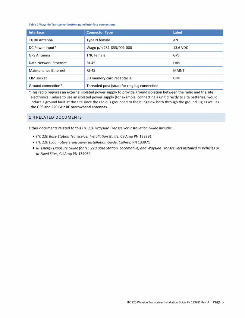
Table 1 Wayside Transceiver bottom panel interface connections
Interface Connector Type Label
TX RX Antenna Type N female ANT
DC Power Input* Wago p/n 231-833/001-000 13.6 VDC
GPS Antenna TNC female GPS
Data Network Ethernet RJ-45 LAN
Maintenance Ethernet RJ-45 MAINT
CIM socket SD memory card receptacle CIM
Ground connection* Threaded post (stud) for ring lug connection
*This radio requires an external isolated power supply to provide ground isolation between the radio and the site electronics. Failure to use an isolated power supply (for example, connecting a unit directly to site batteries) would induce a ground fault at the site since the radio is grounded to the bungalow both through the ground lug as well as the GPS and 220 GHz RF narrowband antennas.
1.4 RELATED DOCUMENTS
Other documents related to this ITC 220 Wayside Transceiver Installation Guide include:
ITC 220 Base Station Transceiver Installation Guide; CalAmp PN 133991
ITC 220 Locomotive Transceiver Installation Guide; CalAmp PN 133971
RF Energy Exposure Guide for ITC 220 Base Station, Locomotive, and Wayside Transceivers Installed in Vehicles or
at Fixed Sites; CalAmp PN 134069

ITC 220 Wayside Transceiver Installation Guide PN 133981 Rev. A | Page 7
2 FOLLOW ESTABLISHED SAFETY GUIDELINES
Your employer has created safety guidelines that apply to your work environment and tasks. Please follow them. If you
have questions about general on-the-job safety concerns, please consult your employer’s established safety guidelines.
2.1 ELECTRICAL SAFETY
To reduce the risk of electric shock:
Follow your employer’s established electrical safety guidelines.
Disconnect power from the transceiver before removing the cover.
Be aware that removing the cover of the radio transceiver may expose you to dangerous voltages or other risks.
Avoid making internal adjustments to the radio transceiver when you are alone.
Avoid contact with a radio’s electrical components. Electric shock from voltages present with the radio transceiver
are potentially fatal.
Reassemble radio transceivers correctly. Incorrect reassembly of a radio transceiver can cause a harmful electric
shock to anyone who handles it.
3 IMPORTANT INFORMATION FOR THE USER
3.1 LIMITING RF EXPOSURE
Caution – Please refer to the RF Energy Exposure Guide for ITC 220 Base Station, Locomotive, and Wayside
Transceivers Installed in Vehicles or at Fixed Sites that is packaged with each Base Station and Locomotive
Transceiver and available online or by request for specific information regarding safe distances that must be
maintained between personnel and energized transmitting antennas.
The information in the RF Energy Exposure Guide for ITC 220 Base Station, Locomotive, and Wayside Transceivers
Installed in Vehicles or at Fixed Sites (RF Energy Exposure Guide) is determined form FCC and Industry Canada rules
that, when followed, limit human exposure to radio frequency energy to acceptable levels. Note that although the
transceiver and antenna are expected to be sited, installed, and maintained only by professionals in a controlled-
exposure environment, the RF Energy Exposure Guide lists the larger lateral safe distances for an uncontrolled
environment. Obeying these limits will protect both railroad employees and the general public.
The Wayside Transceiver is intended to be operated with a fixed antenna in an Occupational/Controlled Exposure
environment per FCC OET 65 or Controlled Use Environment per IC RSS-102. The Maximum Permitted Exposure (MPE)
limit for devices in the presence of the general public in the 100-300 MHz range is 0.2 mW/cm2 = 2 W/m
2 vs. 10 W/m
2
in a controlled-exposure environment.
This radio transceiver is intended for use by railroad employees who have full knowledge of their exposure and can
exercise control over their exposure to meet FCC and IC limits. This radio device is not intended for use by consumers
or the general population. Base station antennas must be positioned on towers or nonresidential buildings that are
generally unoccupied except while servicing the equipment therein.
Table 2 in Section 6 and Table 1 in Section 4 of the RF Energy Exposure Guide list the calculated lateral distances to be
maintained between the general public and an operational transmitter antenna for antenna types suitable in fixed and
mobile applications.

ITC 220 Wayside Transceiver Installation Guide PN 133981 Rev. A | Page 8
Note – RF exposure compliance at multiple transmitter sites must be addressed on a site-by-site basis. It is the responsibility of the licensee to ensure compliance with maximum exposure limits
3.2 FIXED ANTENNA GUIDELINES
This section contains antenna information and additional notes regarding methods to limit RF exposure.
The licensee is required to comply with limits on antenna location, power, and effective antenna height per 47CFR
Subpart T §90.701 et. Seq., or Industry Canada SRSP-512 §6.3 as applicable. The section titled “Wayside-Radiated
Power Limits,” which follows, provides additional information on how to comply with ERP limits.
Refer to the RF Energy Exposure Guide, which is packaged with each Base Station and Locomotive Transceiver and
available online or by request, for specific guidelines regarding placement and installation of fixed antennas.
Acceptable fixed-antenna types are listed in the Rated Power and Recommended Lateral Distance tables in the RF
Energy Exposure Guide.
Install antennas in accordance with the manufacturer’s instructions.
Disable the transmitter when installing or servicing its antenna or transmission line.
Maintain a safe distance from energized transmitting antennas. Refer to the table of safe distances for Base radios
in the RF Energy Exposure Guide.
Unauthorized antennas, equipment modifications, or attachments could invalidate any equipment warranty or
authority to transmit. Modification could damage the radio transceiver and may violate FCC or IC regulations.
Contact CalAmp before using other antennas.
3.3 RF INTERFERENCE TO RESIDENTIAL RECEIVERS
Notice to user: This device complies with Part 15 of the FCC Rules. Operation is subject to the condition that this device
does not cause harmful interference.
Note: this equipment has been tested and found to comply with the limits for a Class B digital device, pursuant to Part
15 of the FCC Rules. These limits are designed to provide reasonable protection against harmful interference in a
residential installation. This equipment generates, uses, and can radiate radio-frequency energy and, if not installed
and used in accordance with the instructions, may cause harmful interference to radio communications. However,
there is no guarantee that interference will not occur in a particular installation. If this equipment does cause harmful
interference to radio or television reception, which can be determined by turning the equipment off and on, the user is
encouraged to try to correct the interference by one or more of the following measures:
Reorient or relocate the receiving antenna.
Increase the separation between the equipment and receiver.
Connect the equipment to an outlet on a circuit different from that to which the receiver is connected.
Consult the dealer or an experienced radio/TV technician for help.
3.4 EQUIPMENT MODIFICATIONS
Caution – Any changes or modifications to this equipment not expressly approved by the party responsible for compliance (in the respective country of use) could void the user’s authority to operate the equipment.
ITC 220 Wayside Transceiver Installation Guide PN 133981 Rev. A | Page 9
4 WAYSIDE TRANSMITTER OPERATION
It is the responsibility of the licensee to operate this radio transmitter in compliance with FCC and Industry Canada
service rules for 220-222 MHz, namely FCC Rules Part 90 Subpart T and Industry Canada SRSP-512.
4.1 WAYSIDE TRANSCEIVER CHANNELIZATION AND FREQUENCY RANGE
The Wayside Transceiver can be configured to transmit on any one of 80 selectable 25 kHz spaced channels ranging
from 220.0125 to 221.9875 MHz inclusive. The spectrum included corresponds to all 5 kHz-wide FCC channels
numbered from 1 at 220.0025 MHz to 400 at 221.9975 MHz. Each Wayside transmission occupies five of the FCC-
defined 5 kHz channels. The lowest radio channel center frequency is in the center of FCC channel 3 and the next is
centered on FCC channel 8, then 13, 18, and so on, up to the highest, which is centered with FCC channel 398.
4.2 WAYSIDE CHANNEL RESTRICTIONS
Section 90.715 of the FCC Rules lists the authorized frequencies of the 400 total 5 kHz wide channels. According to
§90.733(d), these can be aggregated into larger channel widths with the exceptions of FCC channels 161-170 and 181-
185. Therefore, the radio may not transmit on those channels or their 221 MHz counterparts, 361-370 and 381-385.
This corresponds to frequencies 220.8125, 220.8375, 220.9125, 221.8125, 221.8375, and 221.9125 MHz.
Please refer to Part 90 Subpart T and SRSP-512 for additional frequency use restrictions in Canadian and Mexican
border areas.
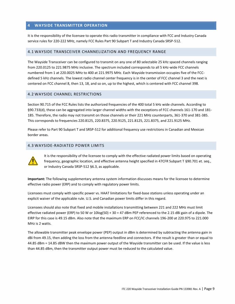
4.3 WAYSIDE-RADIATED POWER LIMITS
It is the responsibility of the licensee to comply with the effective radiated power limits based on operating
frequency, geographic location, and effective antenna height specified in 47CFR Subpart T §90.701 et. seq.,
or Industry Canada SRSP-512 §6.3, as applicable.
Important: The following supplementary antenna system information discusses means for the licensee to determine
effective radio power (ERP) and to comply with regulatory power limits.
Licensees must comply with specific power vs. HAAT limitations for fixed-base stations unless operating under an
explicit waiver of the applicable rule. U.S. and Canadian power limits differ in this regard.
Licensees should also note that fixed and mobile installations transmitting between 221 and 222 MHz must limit
effective radiated power (ERP) to 50 W or 10log(50) + 30 = 47 dBm PEP referenced to the 2.15 dBi gain of a dipole. The
EIRP for this case is 49.15 dBm. Also note that the maximum ERP on FCC/IC channels 196-200 at 220.975 to 221.000
MHz is 2 watts.
The allowable transmitter peak envelope power (PEP) output in dBm is determined by subtracting the antenna gain in
dBi from 49.15, then adding the loss from the antenna feedline and connectors. If the result is greater than or equal to
44.85 dBm = 14.85 dBW then the maximum power output of the Wayside transmitter can be used. If the value is less
than 44.85 dBm, then the transmitter output power must be reduced to the calculated value.
ITC 220 Wayside Transceiver Installation Guide PN 133981 Rev. A | Page 10
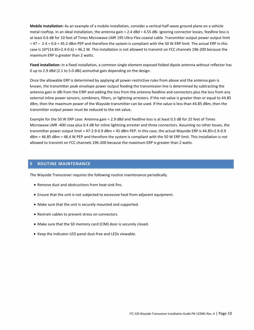
Mobile installation: As an example of a mobile installation, consider a vertical half-wave ground plane on a vehicle
metal rooftop. In an ideal installation, the antenna gain = 2.4 dBd = 4.55 dBi. Ignoring connector losses, feedline loss is
at least 0.6 dB for 10 feet of Times Microwave LMR 195 Ultra Flex coaxial cable. Transmitter output power output limit
= 47 – 2.4 + 0.6 = 45.2 dBm PEP and therefore the system is compliant with the 50 W ERP limit. The actual ERP in this
case is 10^(14.85+2.4-0.6) = 46.2 W. This installation is not allowed to transmit on FCC channels 196-200 because the
maximum ERP is greater than 2 watts.
Fixed installation: In a fixed installation, a common single element exposed folded dipole antenna without reflector has
0 up to 2.9 dBd (2.1 to 5.0 dBi) azimuthal gain depending on the design.
Once the allowable ERP is determined by applying all power-restrictive rules from above and the antenna gain is
known, the transmitter peak envelope power output feeding the transmission line is determined by subtracting the
antenna gain in dBi from the EIRP and adding the loss from the antenna feedline and connectors plus the loss from any
external inline power sensors, combiners, filters, or lightning arresters. If the net value is greater than or equal to 44.85
dBm, then the maximum power of the Wayside transmitter can be used. If the value is less than 44.85 dBm, then the
transmitter output power must be reduced to the net value.
Example for the 50 W ERP case: Antenna gain = 2.9 dBd and feedline loss is at least 0.5 dB for 25 feet of Times
Microwave LMR -400 coax plus 0.4 dB for inline lightning arrester and three connectors. Assuming no other losses, the
transmitter power output limit = 47-2.9-0.9 dBm = 45 dBm PEP. In this case, the actual Wayside ERP is 44.85+2.9-0.9
dBm = 46.85 dBm = 48.4 W PEP and therefore the system is compliant with the 50 W ERP limit. This installation is not
allowed to transmit on FCC channels 196-200 because the maximum ERP is greater than 2 watts.
5 ROUTINE MAINTENANCE
The Wayside Transceiver requires the following routine maintenance periodically.
Remove dust and obstructions from heat-sink fins.
Ensure that the unit is not subjected to excessive heat from adjacent equipment.
Make sure that the unit is securely mounted and supported.
Restrain cables to prevent stress on connectors.
Make sure that the SD memory card (CIM) door is securely closed.
Keep the indicator-LED panel dust-free and LEDs viewable.
ITC 220 Wayside Transceiver Installation Guide PN 133981 Rev. A | Page 11
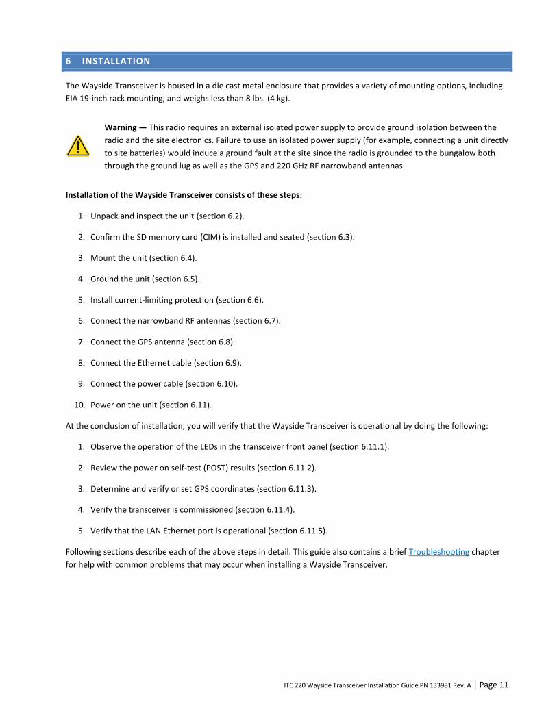
6 INSTALLATION
The Wayside Transceiver is housed in a die cast metal enclosure that provides a variety of mounting options, including
EIA 19-inch rack mounting, and weighs less than 8 lbs. (4 kg).
Warning — This radio requires an external isolated power supply to provide ground isolation between the
radio and the site electronics. Failure to use an isolated power supply (for example, connecting a unit directly
to site batteries) would induce a ground fault at the site since the radio is grounded to the bungalow both
through the ground lug as well as the GPS and 220 GHz RF narrowband antennas.
Installation of the Wayside Transceiver consists of these steps:
1. Unpack and inspect the unit (section 6.2).
2. Confirm the SD memory card (CIM) is installed and seated (section 6.3).
3. Mount the unit (section 6.4).
4. Ground the unit (section 6.5).
5. Install current-limiting protection (section 6.6).
6. Connect the narrowband RF antennas (section 6.7).
7. Connect the GPS antenna (section 6.8).
8. Connect the Ethernet cable (section 6.9).
9. Connect the power cable (section 6.10).
10. Power on the unit (section 6.11).
At the conclusion of installation, you will verify that the Wayside Transceiver is operational by doing the following:
1. Observe the operation of the LEDs in the transceiver front panel (section 6.11.1).
2. Review the power on self-test (POST) results (section 6.11.2).
3. Determine and verify or set GPS coordinates (section 6.11.3).
4. Verify the transceiver is commissioned (section 6.11.4).
5. Verify that the LAN Ethernet port is operational (section 6.11.5).
Following sections describe each of the above steps in detail. This guide also contains a brief Troubleshooting chapter
for help with common problems that may occur when installing a Wayside Transceiver.

ITC 220 Wayside Transceiver Installation Guide PN 133981 Rev. A | Page 12
6.1 REQUIRED EQUIPMENT
Following is a list of test equipment required to perform all of the tests described in this document. It is expected the
user is familiar with the pieces of test equipment listed below. Instructions on how to use the following equipment are
beyond the scope of this document.
Table 2 Required equipment
Type Model Notes
Handheld RF spectrum analyzer Anritsu or equivalent Recommended option for 50 VDC, 50 W input protection of RF signal output port.
Clip-on ammeter
Digital volt meter
Portable power meter
Host computer with at least one Ethernet port and XtermW or equivalent terminal program installed
If the host computer’s Ethernet port has not been configured, then follow the instructions in APPENDIX C— Configure the Computer Ethernet Ports to Communicate with the Transceiver.
Ethernet cable(s) Category 5 or better One Ethernet cable for each computer Ethernet port. Standard Ethernet cable terminated with RJ-45 connectors.
Network analyzer
Portable power meter
Site tester
7/16" and 9/16" wrenches
#2 Phillips head screwdriver
Torque wrench with 65-75 in.·lb. capacity
Cable ties as required
Crimping tool

ITC 220 Wayside Transceiver Installation Guide PN 133981 Rev. A | Page 13
6.2 UNPACK AND INSPECT THE UNIT
Unpack and inspect the Wayside Transceiver. Note any damage that may have resulted from shipping, including dents
or loose parts. Note any damage or discrepancies between the contents in the shipping container and the packing list.
If you detect damage or if the contents do not match the invoice, then note the defect and contact the
manufacturer.
If you do not detect any damage and the shipping invoice matches the contents, then continue with installation.
6.3 CONFIRM SD MEMORY CARD (CIM) IS INSTALLED AND SEATED
Note: The SD memory card must be inserted in the orientation shown on the front panel of the unit.
To confirm the CIM card is installed and seated:
Open the CIM door to ensure the SD memory card is present in the CIM socket.
Push the SD memory card once to release it.
Push the SD memory card again to ensure it is seated in the socket.
Once confirmed, close and secure the CIM door.
Figure 5 CIM card door location and orientation label on Wayside Transceiver
6.4 MOUNT THE WAYSIDE TRANSCEIVER
The Wayside Transceiver is equipped with top and bottom mounting features. It should be mounted vertically for
maximum heat dissipation.
When mounting the Wayside Transceiver, ensure that:
Equipment that produces substantial heat is not installed underneath the Wayside Transceiver.
The areas around the heat-sink fins are not obstructed to allow for proper air flow.
Each Wayside Transceiver is secured with a minimum of two screws at the top and bottom of the unit.
There is adequate clearance to access the SD memory card.
There is adequate clearance for cable connections.
Cables are restrained to prevent kinking and stressing connectors.
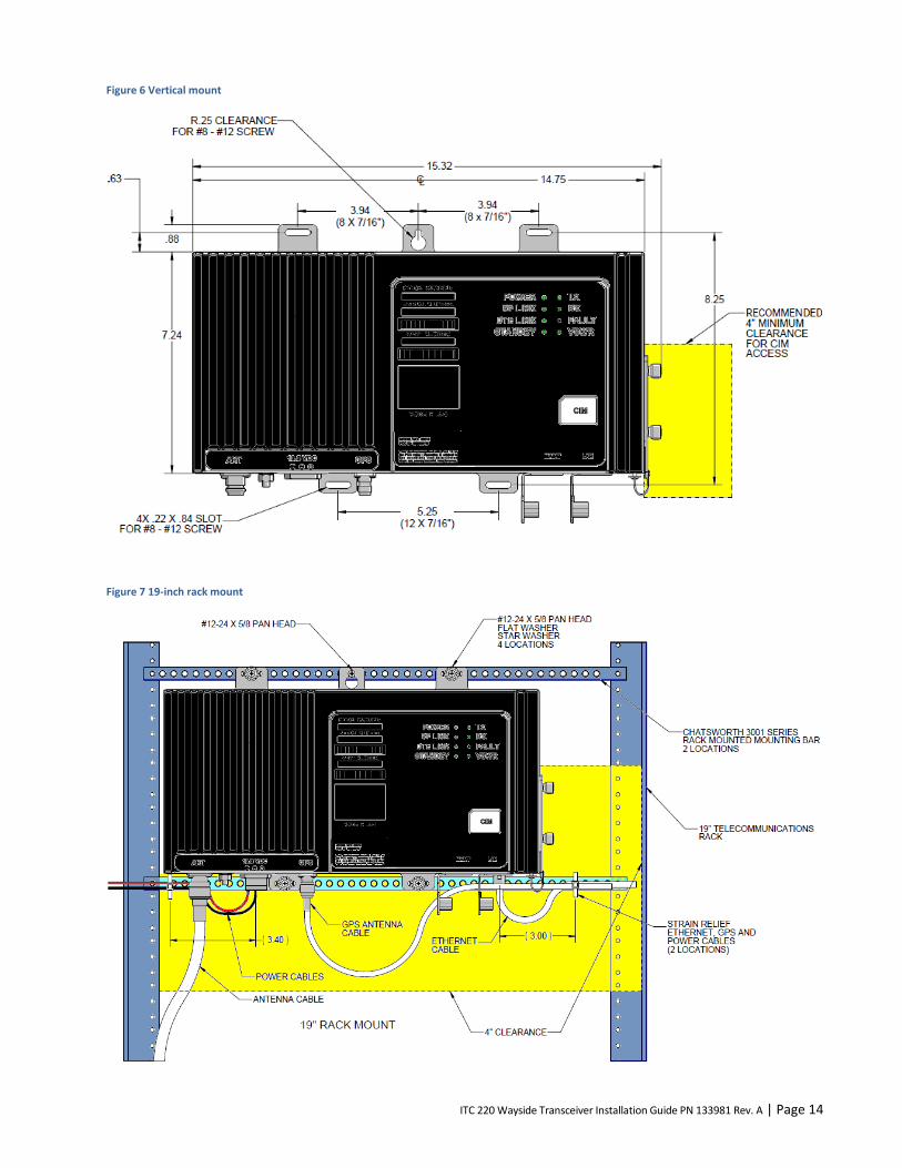
ITC 220 Wayside Transceiver Installation Guide PN 133981 Rev. A | Page 14
Figure 6 Vertical mount
Figure 7 19-inch rack mount

ITC 220 Wayside Transceiver Installation Guide PN 133981 Rev. A | Page 15
Warning – Anchor the rack according to your local building codes and standards.
After mounting, ensure that:
Equipment that produces substantial heat is not installed underneath the Wayside Transceiver.
The areas around the heat-sink fins are not obstructed to allow for proper air flow.
Each Wayside Transceiver is secured with a minimum of two screws at the top and bottom of the unit.
There is adequate clearance to access the SD memory card.
There is adequate clearance for cable connections.
Cables are restrained to prevent kinking and stressing connectors.
6.5 GROUND THE RADIO TRANSCEIVER
Warning — This radio requires an external isolated power supply to provide ground isolation between the
radio and the site electronics. Failure to use an isolated power supply (for example, connecting a unit directly
to site batteries) would induce a ground fault at the site since the radio is grounded to the bungalow both
through the ground lug as well as the GPS and 220 GHz RF narrowband antennas.
Warning — Ensure the radio is grounded. Not grounding the radio could result in possible bodily injury.
The Wayside Transceiver has a 1/4 inch grounding stud in the bottom of the unit (located between Type N female
connector for TX RX antenna connection and the power connector receptacle).
Figure 8 Grounding stud
To ground the Wayside Transceiver:
Note: The radio needs to be grounded to a proper isolated converter such as the Wilmore DC-DC isolated converter
(P/N 1675-12-12-15) or equivalent.
1. Remove the nut and internal-tooth lock washer from the grounding stud.
2. Connect a grounding wire with ring lugs to ground.
3. Reinstall the internal-tooth lock washer and nut, removed earlier, and tighten outer nut to a maximum torque of
65-75 in.·lbs. for the ¼-20 nut.
ITC 220 Wayside Transceiver Installation Guide PN 133981 Rev. A | Page 16
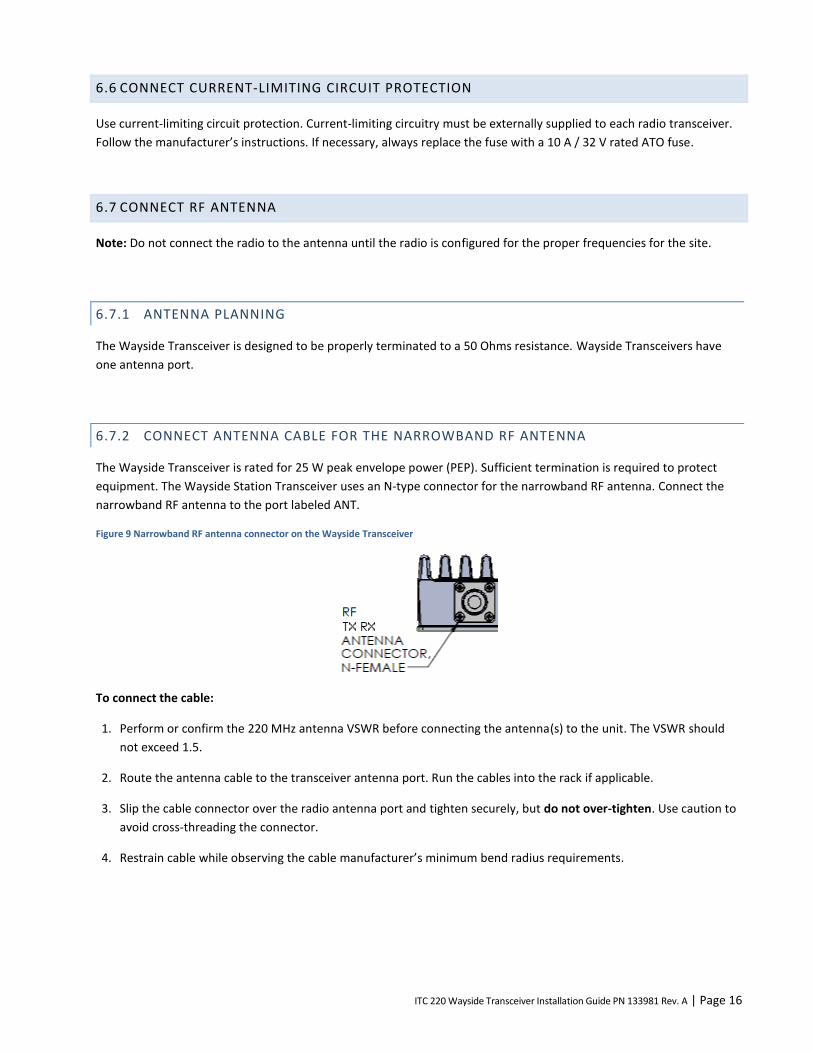
6.6 CONNECT CURRENT-LIMITING CIRCUIT PROTECTION
Use current-limiting circuit protection. Current-limiting circuitry must be externally supplied to each radio transceiver.
Follow the manufacturer’s instructions. If necessary, always replace the fuse with a 10 A / 32 V rated ATO fuse.
6.7 CONNECT RF ANTENNA
Note: Do not connect the radio to the antenna until the radio is configured for the proper frequencies for the site.
6.7.1 ANTENNA PLANNING
The Wayside Transceiver is designed to be properly terminated to a 50 Ohms resistance. Wayside Transceivers have
one antenna port.
6.7.2 CONNECT ANTENNA CABLE FOR THE NARROWBAND RF ANTENNA
The Wayside Transceiver is rated for 25 W peak envelope power (PEP). Sufficient termination is required to protect
equipment. The Wayside Station Transceiver uses an N-type connector for the narrowband RF antenna. Connect the
narrowband RF antenna to the port labeled ANT.
Figure 9 Narrowband RF antenna connector on the Wayside Transceiver
To connect the cable:
1. Perform or confirm the 220 MHz antenna VSWR before connecting the antenna(s) to the unit. The VSWR should
not exceed 1.5.
2. Route the antenna cable to the transceiver antenna port. Run the cables into the rack if applicable.
3. Slip the cable connector over the radio antenna port and tighten securely, but do not over-tighten. Use caution to
avoid cross-threading the connector.
4. Restrain cable while observing the cable manufacturer’s minimum bend radius requirements.

ITC 220 Wayside Transceiver Installation Guide PN 133981 Rev. A | Page 17
6.8 CONNECT THE GPS ANTENNA
Position the GPS antenna to avoid strong interference that could saturate the antenna low-noise amplifier or the radio
GPS receiver low-noise amplifier. Combinations of strong interferers could mix and interfere directly with the GPS
signal quality. Test the transceiver GPS with any interference source active to qualify the antenna-antenna isolation of
the GPS antenna position. See APPENDIX B— GPS Satellite Constellation Overview and Antenna Planning
Considerations, if necessary, for reference. Because GPS satellites are not stationary, but move throughout the sky,
install the GPS antenna where it will have clear visibility to as much of the entire sky as possible. (Not just the southern
sky, as for geosynchronous satellite reception.)
The Wayside Transceiver uses a TNC female connector for GPS antenna connection and always provides an active
antenna voltage. If the active antenna installed exceeds either the voltage or current ability of the transceiver, then
external power must be supplied to the antenna. A DC block must be used at the transceiver when the additional
power is supplied, to avoid damage to the transceiver. It is recommended that the cable length not exceed 30 meters.
To connect the GPS antenna
1. Confirm the GPS antenna has been verified.
2. Verify the power requirement of the GPS antenna and connect a DC block and tee in the case external power is
necessary.
3. Connect the GPS antenna cable to the GPS antenna input connector on the transceiver and tighten securely—but
use caution to not over-tighten. Use caution to avoid cross-threading the connector.
Figure 10 GPS connector
6.9 CONNECT THE ETHERNET CABLE
The Wayside Transceiver uses standard Category 5 (or better) Ethernet cable with an RJ-45 connector. It is
recommended that the cable length not exceed 100 meters. Insert the RJ-45 Ethernet cable connector into the RJ-45
jack labeled LAN.
Figure 11 Ethernet connector jacks in the bottom of the Wayside Transceiver

ITC 220 Wayside Transceiver Installation Guide PN 133981 Rev. A | Page 18
6.10 CONNECT THE POWER CABLE
Warning – Applying an incorrect voltage to the Wayside Transceiver can cause damage. Confirm the voltage
rating of the Transceiver and power source before applying power.
Warning – This radio requires an external isolated power supply to provide ground isolation between the
radio and the site electronics. Failure to use an isolated power supply (for example, connecting a unit directly
to site batteries) would induce a ground fault at the site since the radio is grounded to the bungalow both
through the ground lug as well as the GPS and 220 GHz RF narrowband antennas.
The Wayside Transceiver operates from a 13.6 VDC nominal power supply (10.9 to 15.5 VDC range) isolated from other
electronic equipment using a DC-DC isolated converter such as the Wilmore Model 1675-12-12-15. The Wayside
Transceiver uses a Wago-type connector supplying 10.9 to 15.5 VDC.
Important! The transceiver does not have a power switch. Applying power to the power port powers it on. Do not
connect the transceiver to power until instructed to do so later in these instructions. Verify that the power is off before
connecting the unit to a power source.
Figure 12, which follows, shows an example of a typical constructed power cable.
Figure 12 Example of a typical power cable externally fused with 10 A ATO
Figure 13 Wayside Transceiver power connector
ITC 220 Wayside Transceiver Installation Guide PN 133981 Rev. A | Page 19
To connect the power cable:
1. The Wayside Transceiver does not have a power switch. Verify that the power is off before connecting the unit to a
power source.
2. Run the power cable to the unit. Insert the power plug into the transceiver power port. The plug can only fit in one
direction. Make sure the red wire is connected to the slot marked +.
3. Confirm proper grounding.
4. Verify the ground bond from the ground lug on the transceiver through external surge protection.
5. Confirm the ground lug connection has not bypassed the isolator converter.
6. Restrain the cables, observing the cable manufacturer’s minimum bend radius requirements.
6.11 POWER ON THE TRANSCEIVER
Caution – Power should never be applied to any system unless the user is acutely aware of his intentions and
the environment in which the unit is operating. Applying power to an improperly-terminated radio
transceiver could result in damage to the radio transceiver, cause operator injury, or violate regulatory laws
regarding radio transceiver transmissions as radios will begin transmitting full-rated power without any user
intervention under certain conditions.
To power on the radio transceiver:
Make sure your computer network card is configured with a fixed IP address of 192.168.255.200. See Appendix C—
Configure the Computer Ethernet Ports to Communicate with the Transceiver for more information.
1. Connect the computer through the MAINT port on the radio transceiver with an Ethernet cable.
2. Start an XtermW session.
3. Confirm that all radio transceiver connections are secure.
4. Power on the transceiver.
5. Ensure the breaker did not trip on startup.
Caution – Take care to not power-cycle the transceiver off and on repeatedly within four minutes of
powering it on. Subjecting the transceiver to three or more successive power cycles within four minutes can
cause a reboot error. If a reboot error occurs, remove power, replace the SD card, and then apply power and
allow the transceiver to boot up normally without power interruptions.
6.11.1 LED DIAGNOSTICS
A blinking PWR (Power) LED on the front panel indicates that the boot sequence has completed. The Ethernet port
connection becomes active within 10 seconds, allowing you to start an XtermW session.

ITC 220 Wayside Transceiver Installation Guide PN 133981 Rev. A | Page 20
The front panel LEDs show the general operational status of the transceiver after it has conducted a POST, which it
does each time it boots up. Table 3 Front panel LEDs includes a description of the function of each LED as well as the
color of each LED when the transceiver is functioning properly.
Note: If a problem occurs after the transceiver boots up, the front panel LEDs indicate the problem only after a reboot
of the transceiver (provided the problem persists).
Read the description of each LED carefully. Some LEDs, such as the PWR LED, indicate a problem if they do not light.
The FLT (Fault) and SWR LEDs indicate a problem if they are lit.
Table 3 Front panel LEDs
Label Description Color
PWR Power — Blinking green LED indicates that the unit is on. Green
TX Illuminates when the radio transmitter is keyed. Red
VSWR Illuminates when the VSWR of the TX port exceeds approximately 3:1. Illuminates if the TX forward power is not within 25% of the RF output power setting. (A time-stamped entry specifying the cause will display in the XtermW window.)
Red
RX Illuminates when the transceiver is receiving a valid 220 MHz PTC signal. Amber
DTE Link Illuminates when the transceiver establishes a connection to a Communication Manager (CM) through the Ethernet network port.
Amber
RF Link Illuminates when an RF link is established between two radios. Amber
STANDBY Illuminates when the transceiver is in standby mode, indicating TX is disabled. Red
FAULT When illuminated, it indicates a variety of fault conditions not indicated by other LEDs. Possible faults indicated by the Fault LED include:
One or more internal radio supply voltages are below the minimum threshold.
The extended DC voltage to the transceiver is outside of the acceptable range.
One or more of the transceiver’s internal sensors is indicating a temperature exceeding the allowable threshold.
The transceiver failed one or more self tests at power on.
TX forward power is not within 25% of the RF output power setting.
The CIM script file is not present or has invalid or corrupt data. If the Fault LED illuminates, a time-stamped entry will display in XtermW specifying the cause.
Red
6.11.2 REVIEW THE POWER ON SELF-TEST (POST) RESULTS
A POST is a series of several dozen tests that the transceiver quickly runs on itself, each time it boots up, to determine if
it has a problem or is missing critical information. The radio boots up when it is powered on or the BOOT command is
issued at the command line. Entering the POST command multiple times does not cause the tests to be re-run since
one execution of the tests is automatic at each power on.
POST results show whether the transceiver has passed a test, indicated by PASS, or failed a test, indicated by FAIL. The
results do not appear on the transceiver, which has no display screen. Instead, you send a command to the radio and
view the results on your computer monitor.
To view POST results, remove and reconnect DC power. The transceiver will automatically run internal diagnostics. A
blinking green PWR LED on the front panel indicates that the boot sequence has completed. Within 10 seconds the
Ethernet port becomes active.
ITC 220 Wayside Transceiver Installation Guide PN 133981 Rev. A | Page 21
Make sure your computer network card has a fixed IP address of 192.168.255.200. See APPENDIX C — Configure the
Computer Ethernet Ports to Communicate with the Transceiver for instructions.
To display the POST results:
1. Connect the computer to the transceiver MAINT port using a standard Category 5 or better Ethernet cable.
2. On the computer, open the XtermW application.
3. Click Send, click Command, and then type:
POST
4. Click OK.
5. View the POST results list. See APPENDIX D— Sample POST Results from a Properly Functioning Wayside
Transceiver.
6.11.3 DETERMINE AND VERIFY OR SET GPS COORDINATES
Wayside Transceivers, because it is generally known where each will be installed, may have default GPS coordinates
already entered as part of system planning and configured before shipment. For the most part, this works to the
advantage of the installer. A hidden risk where this can become problematic though, is where a replacement Wayside
Transceiver is used to replace a non-working unit or where a Wayside Transceiver intended for installation at one
location is substituted for another at a different location. In these cases, if a GPS location has been programmed into
the system, it is most likely wrong. In any case, because being configured with the correct global position of the
Wayside Transceiver is essential to its proper function, it is important to determine and verify—and if necessary
correct—the GPS coordinates configured in the Wayside Transceiver.
APPENDIX B — GPS Satellite Constellation Overview and Antenna Planning Considerations provides a general overview
of GPS as it relates to the system. If you are not familiar with the concepts, it is good reference material. The sections
that are important here are those contained in B.2.2 Determine GPS Coordinates.
If the GPS coordinates of the Wayside Transceiver location are known use the instructions and example contained in
Surveyed position obtained offline to enter the GPS coordinates and configure the transceiver to use GPS Manual
mode.
If the GPS coordinates are not known or the transceiver will be used in a mobile application, use instructions and
example contained in GPS determines its own position, to configure the transceiver to use Survey mode.
Note: If you choose to have the Wayside Transceiver continue to use Survey mode (for example where the transceiver
will be used in a mobile application), DO NOT enter GPS coordinates in the CIM script.
6.11.4 VERIFY THE TRANSCEIVER IS COMMISSIONED
With the computer still connected to the transceiver MAINT port, use the COMMISSION command to determine
whether the radio is commissioned and if not to commission it.

ITC 220 Wayside Transceiver Installation Guide PN 133981 Rev. A | Page 22
To determine whether the transceiver has been commissioned and if necessary commission the transceiver:
1. If it is not already connected, connect the computer to the transceiver MAINT port using a Category 5 or better
Ethernet cable.
2. On the computer, open the XtermW application.
3. Click Send, click Command, and then type:
COMMISSION
4. Click OK.
The transceiver will return a Commission status of either “Radio State: COMMISSIONED” or “Radio State:
UNCOMMISSIONED.”
If the transceiver returns a status of “Radio State: COMMISSIONED,” the transceiver has been commissioned
and you can continue on to the next step Verify LAN Ethernet Port is Operational.
If the transceiver returns a status of “Radio State: UNCOMMISSIONED,” do the following to commission the
transceiver:
1. In the XtermW application, click Send, click Command, and then type:
COMMISSION,COMMISSION
2. Click OK.
The transceiver will return the status of “Radio State: COMMISSIONED.” The transceiver has been
commissioned and you can continue on to the next step Verify LAN Ethernet Port is Operational.
6.11.5 VERIFY LAN ETHERNET PORT IS OPERATIONAL
Configure the Ethernet port (or second Ethernet port) of the test computer for connection to the Transceiver LAN port,
then connect an Ethernet cable to connect these ports. The test computer should display an active network connection
on the port (indicated in the System Tray in Windows XP) within 60 seconds.
ITC 220 Wayside Transceiver Installation Guide PN 133981 Rev. A | Page 23
7 TROUBLESHOOTING
This section describes common problems, their possible causes, and likely solutions. It covers the following problems:
Power
SD memory card
Antenna
Transmission
Reception
Ethernet connectivity
RF link
In each of the following sections, a troubleshooting table lists solutions to these problems in the order you should try
them. Solutions that require more than one step are described in detail in Transceiver test and adjustment procedures.
7.1 GUIDELINES FOR TROUBLESHOOTING COMMON PROBLEMS
Always check these items first when a transceiver problem occurs.
Check physical connections.
Make sure that all physical connections to the transceiver are secure. This includes: Ethernet (LAN port), power,
narrowband RF antenna, and GPS.
Check that the SD card is present, seated, and contains a valid CIM script file.
Make sure that there is an SD card installed and seated that contains a valid CIM script file. Without an SD card
present and without a valid CIM script, the transceiver will not transmit and will continually reboot every few
minutes.
Check the LEDs.
Use the LEDs to determine the state of the system and whether there is a fault condition. See LED Diagnostics for
more information. (A time-stamped entry will display in XtermW if the Fault or SWR LEDS illuminate.)
Determine the version of software each transceiver is running.
Check the results of the REV command to determine what revision of software is running. All transceivers should be
running software version 1.1.15.05 or later.
Check the POST results.
Review the output of the POST command on the transceiver to ensure that no tests failed during the most recent
power-on self test. See Review the Power On Self-Test (POST) Results for more information.
Check that the transceiver configuration is up to date.
Run INICHECK to see if the transceiver configuration matches the current CIM script file. To run the CIM script in
the event that they are not the same, use: INICHECK,SCRIPT

ITC 220 Wayside Transceiver Installation Guide PN 133981 Rev. A | Page 24
7.2 POWER PROBLEMS
Problem indicators:
There is no power to the transceiver — as indicated by the PWR (Power) LED does not illuminate or blink.
The transceiver does not transmit.
The POST results show that internal voltages are low.
To troubleshoot transceiver power issues:
1. Make sure the power cable connectors are securely connected to the power supply and to the transceiver.
2. Make sure the power cable polarity is correct: the red wire is connected to the unit’s positive (+) terminal and the
black wire is plugged into the negative (–) terminal. See Figure 12 Example of a typical power cable .
3. Check that the power supply is turned on. If it is off, then turn it on. Verify that the breaker does not trip on power
up.
4. Adjust the power supply to within the rated operating voltage.
5. Verify that the current limit on the power supply meets the maximum current draw. See Table 4 Wayside
Transceiver input power parameters .
6. Replace the power cable.
7. Replace the transceiver. When replacing a transceiver, if the SD card contains a valid CIM script, remove the SD
memory card from the nonworking transceiver and insert and seat it in the replacement transceiver. The
replacement transceiver will use the CIM script on the SD memory card and its configuration will be the same as
the original transceiver.
7.3 SD MEMORY CARD PROBLEMS
SD memory card problems are one type of problem that can cause the Fault LED to illuminate.
You can determine the specific problem that causes the Fault LED to illuminate by viewing the results of the POST,
which occurs each time the transceiver boots up.
The POST results will show if there is an SD memory card failure. See Review the Power On Self-Test (POST) Results.
The following shows what you will see in the SD memory card portion of the POST results if the SD memory card is
missing:
HOST: SDCARD Present: FAIL
HOST: SDCARD Fail Pin: PASS
HOST: SDCARD Write Protect: OFF
HOST: SDCARD Access: FAIL
To troubleshoot SD memory card issues:
1. Check to make sure the SD memory card is present. See Confirm SD Memory Card (CIM) is Installed and Seated. If
it is missing or defective, replace it with a new SD card that contains a valid CIM script file.
ITC 220 Wayside Transceiver Installation Guide PN 133981 Rev. A | Page 25
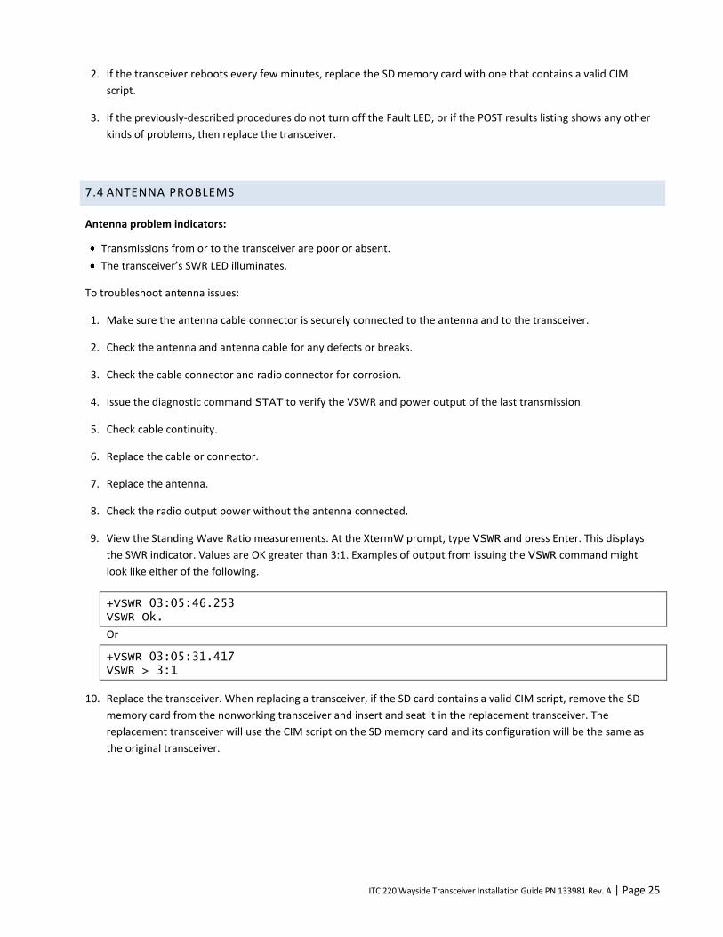
2. If the transceiver reboots every few minutes, replace the SD memory card with one that contains a valid CIM
script.
3. If the previously-described procedures do not turn off the Fault LED, or if the POST results listing shows any other
kinds of problems, then replace the transceiver.
7.4 ANTENNA PROBLEMS
Antenna problem indicators:
Transmissions from or to the transceiver are poor or absent.
The transceiver’s SWR LED illuminates.
To troubleshoot antenna issues:
1. Make sure the antenna cable connector is securely connected to the antenna and to the transceiver.
2. Check the antenna and antenna cable for any defects or breaks.
3. Check the cable connector and radio connector for corrosion.
4. Issue the diagnostic command STAT to verify the VSWR and power output of the last transmission.
5. Check cable continuity.
6. Replace the cable or connector.
7. Replace the antenna.
8. Check the radio output power without the antenna connected.
9. View the Standing Wave Ratio measurements. At the XtermW prompt, type VSWR and press Enter. This displays
the SWR indicator. Values are OK greater than 3:1. Examples of output from issuing the VSWR command might
look like either of the following.
+VSWR 03:05:46.253 VSWR Ok.
Or
+VSWR 03:05:31.417 VSWR > 3:1
10. Replace the transceiver. When replacing a transceiver, if the SD card contains a valid CIM script, remove the SD
memory card from the nonworking transceiver and insert and seat it in the replacement transceiver. The
replacement transceiver will use the CIM script on the SD memory card and its configuration will be the same as
the original transceiver.

ITC 220 Wayside Transceiver Installation Guide PN 133981 Rev. A | Page 26
7.5 TRANSMISSION PROBLEMS
Problem indicators:
Transmissions from the transceiver are weak or intermittent.
A transceiver in the network stops receiving expected communications from the transceiver.
The TX LED is off.
To troubleshoot transmission issues:
1. Make sure the transceiver is turned on and the green PWR LED illuminates and blinks.
2. Issue the diagnostic command STAT to confirm the power output of the last transmission and VSWR.
3. Check the cable connector and the radio connector for corrosion. If there is evidence of corrosion, then replace the
connector.
4. Check the temperature of the radio and confirm the PA (Power Amplifier) temperature has not exceeded the over-
temperature threshold using the TXSTAT command to query the transmitter status.
+txstat
Sniffer – FALSE CLI – FALSE Temperature – FALSE Voltage – FALSE CIM – FALSE Canned Msg – FALSE Test Mode – FALSE StartUp - FALSE
Transmitter State – Available
5. Inspect the SD memory card to ensure it is seated properly in the CIM socket in the orientation shown and is not
damaged.
6. Make sure there is a valid CIM script file loaded from the SD card. At the XtermW prompt, enter INICHECK,
SCRIPT.
7. Make sure the antenna cable connectors are securely connected to the antenna and to the radio connectors.
8. Adjust the power output higher and lower to verify the transmission is controllable.
9. Monitor the current supplied by the power supply to confirm the typical transmit current is drawn and the radio is
not current limited.
10. Check the antenna for any defects or breaks.
11. Adjust the power supply voltage, if necessary. If the power supply voltage is too low, the transceiver might stop
transmitting.
12. Adjust the transceiver power level, if necessary. The transceiver might stop transmitting if the voltage is too low.
13. Replace the cable or connector.
14. Replace the transceiver. When replacing a transceiver, if the SD card contains a valid CIM script, remove the SD
memory card from the nonworking transceiver and insert and seat it in the replacement transceiver. The

ITC 220 Wayside Transceiver Installation Guide PN 133981 Rev. A | Page 27
replacement transceiver will use the CIM script on the SD memory card and its configuration will be the same as
the original transceiver.
7.6 RECEPTION PROBLEMS
Problem indicators
A transceiver in the network stops receiving communications from another transceiver.
The RX LED is off.
To troubleshoot receiver issues:
1. Make sure the transceiver is turned on and the PWR LED illuminates and blinks.
2. Verify the transmit frequency is within limits. See Operational Characteristics.
3. Verify the antenna cable connectors are securely connected to the antenna and the transceiver.
4. Verify that the antenna is connected to the narrowband RF antenna input connector at the bottom of the unit.
5. Check the cable connector and transceiver connector for corrosion.
6. Replace the cable or connector.
7. Check the antenna for any defects or breaks.
8. Replace the transceiver. When replacing a transceiver, if the SD card contains a valid CIM script, remove the SD
memory card from the nonworking transceiver and insert and seat it in the replacement transceiver. The
replacement transceiver will use the CIM script on the SD memory card and its configuration will be the same as
the original transceiver.
7.7 ETHERNET CONNECTIVITY PROBLEMS
Problem indicators:
The transceiver is disconnected from the Ethernet network.
The DTE Link LED is off.
To troubleshoot network connectivity issues:
If you cannot directly connect to the MAINT port on the transceiver, then contact your system administrator.
1. Check network activity, for example, by using Wireshark software (or equivalent) and a computer. If the network is
down, persons responsible for the network administration will need to restore network operation.
2. Make sure the Ethernet cable is securely connected to the transceiver LAN port.
3. Verify external network equipment is functioning properly.

ITC 220 Wayside Transceiver Installation Guide PN 133981 Rev. A | Page 28
4. Connect your computer to the transceiver LAN port. See C.2 To Configure the Computer Ethernet 2 Interface for
Communication with the Transceiver LAN Port. Send a command to the transceiver LAN port and then see if the
transceiver responds.
Note: To communicate with the transceiver’s LAN port, the computer’s connected Ethernet port must be
configured to do so. You must know the LAN port’s IP address. If you do not know the IP address, contact the
system administrator.
5. Replace the Ethernet cable.
6. Replace the transceiver. When replacing a transceiver, if the SD card contains a valid CIM script, remove the SD
memory card from the nonworking transceiver and insert and seat it in the replacement transceiver. The
replacement transceiver will use the CIM script on the SD memory card and its configuration will be the same as
the original transceiver.
7.8 RF LINK PROBLEMS
When the RF Link LED illuminates, it means that the Wayside transceiver has selected and connected to a Base Station
transceiver. When the LED is off, it could mean that the Base Station transceiver has not communicated with the
Wayside transceiver for a specified time.
Problem indicators:
The RF Link LED is off.
To troubleshoot RF link issues:
1. Make sure the transceiver is turned on and the green PWR LED illuminates and blinks.
2. Make sure the antenna cable connectors are securely connected to the antenna and to the transceiver.
3. Inspect the SD memory card to ensure it is not damaged and is seated properly in the CIM socket.
4. Make sure there is a valid CIM script file loaded from the SD card. At the XtermW prompt, enter
INICHECK,SCRIPT.
5. Check the antenna for any defects or breaks.
6. In XtermW, run the STAT,RF command. This command displays the total number of packets transmitted and
received by the radio. Statistics are broken down by packet type. There are also several running totals included.

ITC 220 Wayside Transceiver Installation Guide PN 133981 Rev. A | Page 29
Example:
+stat,rf 19:28:54.282 Bytes Tx: 33213 Rx: 191 Segments Tx: 4 Rx: 4 Corr: 0 Bad: 0 Packets Tx: 2 Rx: 13 AckedPkts Ak: 2 NonAckPkts Tx: 2340 CtlPkt Tx: 2285 Rx: 0 Util Out: 449 In: 104 HPCSMA: 105098 APCSMA: 105117 QStatPkt Tx: 0 Rx: 6 BaseBeacon Tx: 35 Rx: 0 AckPkt Tx: 0 Rx: 2 AcqPkt Tx: 0 Rx: 1 PosPkt Tx: 0 Rx: 0 TodPkt Tx: 20 Rx: 0 BcastShort Tx: 0 Rx: 0 BcastLoc Tx: 0 Rx: 0 BcastComm Tx: 0 Rx: 0 UniLocal Tx: 2 Rx: 4 UniLocal Ak: 2 UniCommon Tx: 0 Rx: 0 UniCommon Ak: 0 UniBdcst Tx: 0 Rx: 0 OtherLocal Tx: 0 Rx: 0 OtherLocal Ak: 0 OtherComm Tx: 0 Rx: 0 OtherComm Ak: 0 Illegal Rx: 0 Messages Tx: 2 Rx: 2
7. Use the BBeacon command to ensure that the base beacons are configured for the common channel.
8. Replace the transceiver. When replacing a transceiver, if the SD card contains a valid CIM script, remove the SD
memory card from the nonworking transceiver and insert and seat it in the replacement transceiver. The
replacement transceiver will use the CIM script on the SD memory card and its configuration will be the same as
the original transceiver.

ITC 220 Wayside Transceiver Installation Guide PN 133981 Rev. A | Page 30
APPENDIX A — ABBREVIATIONS AND DEFINITIONS
A: Ampere, or Amp; measure of electric current
AWG: American Wire Gauge (a measure of wire
diameter)
BER: Bit Error Rate
CIM: Configuration Interface Module
cm: Centimeter
Common Channel: A CSMA-operated channel common
to all Base Station, Locomotive, and Wayside
Transceivers in the system. Every radio transceiver in
the system should have the same common channel.
CSMA: Carrier Sense Multiple Access
CW: Constant Wave
dB: Decibel
dBd: Decibel, dipole
dBi: Decibel, isotropic
dBm: Decibel, referenced to one milliwatt
DC: Direct Current
DCE: Data Communication Equipment
DTDMA: Dynamic Time Division Multiple Access
DOP Dilution of Precision
DQPSK: Differential Quaternary Phase-Shift Keying
EIA: Electronic Industries Alliance
EIRP: Equivalent Isotropically Radiated Power
ERP: Effective Radiated Power
EVM: Error Vector Magnitude
FCC: Federal Communications Commission (U.S.)
FRA: Federal Railroad Administration (U.S.)
FTDMA: Fixed Time Division Multiple Access
GPS: Global Positioning System
HAAT: Height Above Average Terrain
IC: Industry Canada (Canada)
ITC: Interoperable Train Control
ITCR: Interoperable Train Control Radio
kbps: Kilobits per Second
LAN: Local Area Network
LOS: Line of Sight
Local Channel: A frequency assigned to each Base
Transceiver (DTDMA and FTDMA) and Wayside
Transceiver (FTDMA)
m: Meter
Mbps: Megabits Per Second
MEO: Medium Earth Orbit
MHz: Megahertz
MPE: Maximum Permissible Exposure
MSGPS: Multi-Satellite Global Positioning System
mW: Milliwatt
NIC: Network Interface Card or Network Interface
Controller
PC: Personal Computer
PCA: Printed Circuit Assembly
PCB: Printed Circuit Board
PEP: Peak Envelope Power
PER: Packet Error Rate
POST: Power On Self Test
PPM: Parts Per Million
PSK: Phase Shift Keying

ITC 220 Wayside Transceiver Installation Guide PN 133981 Rev. A | Page 31
PSWR: Power Standing Wave Ratio
PTC: Positive Train Control
Radio ID: Radio Identifier; A unique identifier assigned
to each radio transceiver in the system
RF: Radio Frequency
RSSI: Received Signal Strength Indicator
RTCS: Radio Test Control Simulator
RX: Receive
SAR: Specific Absorption Rate
SD memory card: Secure Digital memory card
SMA connector: SubMiniature version A connector
SRSP: Standard Radio System Plan (Canada)
TCP/IP: Transmission Control Protocol / Internet
Protocol
TCXO: Temperature-Compensated Crystal Oscillator
TNC connector: Threaded Neill-Concelman connector
TX: Transmit
U: Unit measure of height for rack-mounted
equipment, defined 44.5 mm (approximately 1¾ in) for
rack-mounted equipment that conforms to EIA 19-inch
rack standards
UUT: Unit Under Test
VDC: Voltage, Direct Current
VSWR: Voltage Standing Wave Ratio
W: Watt
XtermW: The terminal-emulation application used for
configuring and testing ITC 220 Transceivers

ITC 220 Wayside Transceiver Installation Guide PN 133981 Rev. A | Page 32
APPENDIX B — GPS SATELLITE CONSTELLATION OVERVIEW AND ANTENNA PLANNING
CONSIDERATIONS
B.1 GPS SATELLITE CONSTELLATION OVERVIEW
The current GPS satellite constellation is comprised of 30 active satellites in six inclined orbits, with several on-orbit
spares. The GPS satellites operate in circular, approximately 11-hour and 58 minute orbits, at an inclination of 55
degrees at an altitude of 20,200 km.
Figure 14 — GPS satellite constellation
This type of satellite is referred to as an MEO (Medium Earth Orbit) satellite. They are not in geostationary orbit. This is
important because unlike GEO (Geostationary Earth Orbit) satellites, which are located at an altitude of 37,790 km over
the equator, MEO satellites move throughout most of the sky, so there is no significantly preferential sky visibility
sector when installing the GPS antennas at the site. The GPS antenna location selection must be optimized for as much
sky visibility as possible in all directions, not just to the South.
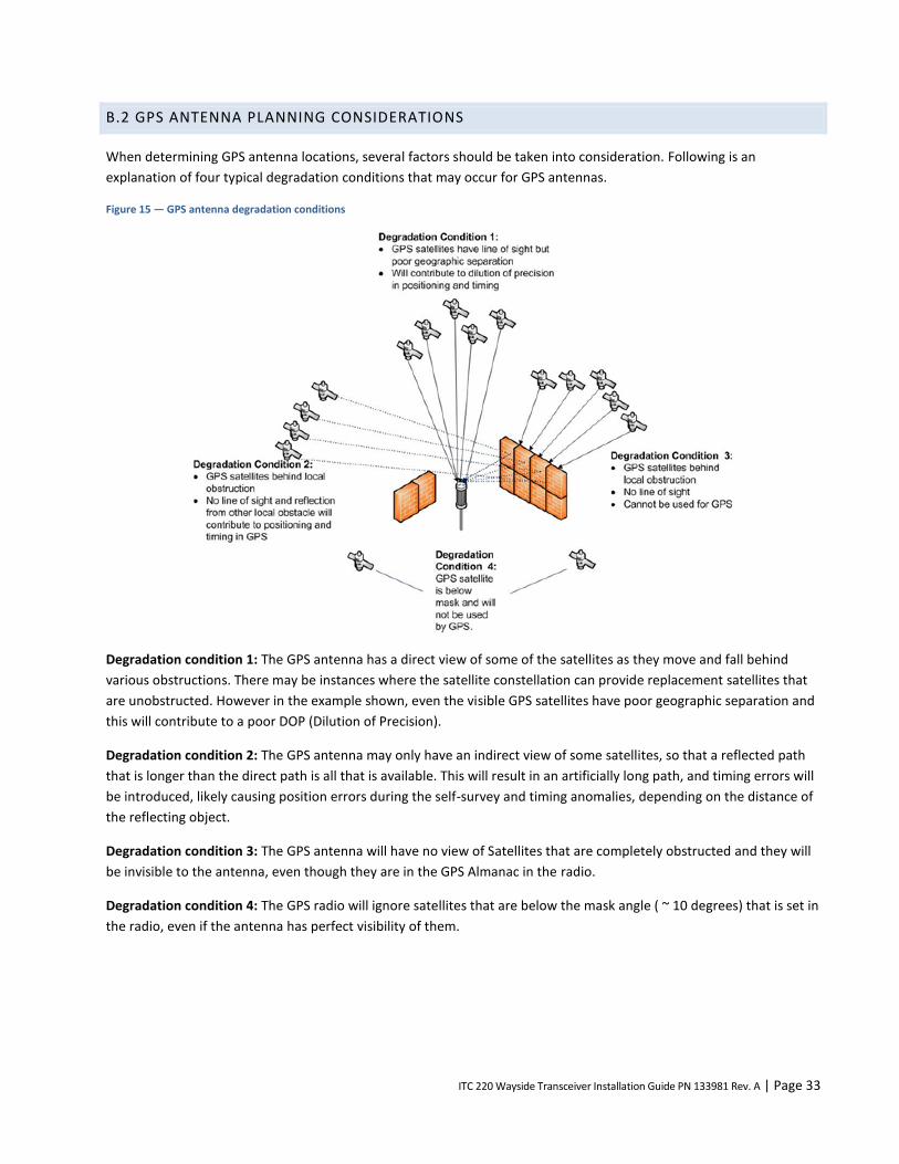
ITC 220 Wayside Transceiver Installation Guide PN 133981 Rev. A | Page 33
B.2 GPS ANTENNA PLANNING CONSIDERATIONS
When determining GPS antenna locations, several factors should be taken into consideration. Following is an
explanation of four typical degradation conditions that may occur for GPS antennas.
Figure 15 — GPS antenna degradation conditions
Degradation condition 1: The GPS antenna has a direct view of some of the satellites as they move and fall behind
various obstructions. There may be instances where the satellite constellation can provide replacement satellites that
are unobstructed. However in the example shown, even the visible GPS satellites have poor geographic separation and
this will contribute to a poor DOP (Dilution of Precision).
Degradation condition 2: The GPS antenna may only have an indirect view of some satellites, so that a reflected path
that is longer than the direct path is all that is available. This will result in an artificially long path, and timing errors will
be introduced, likely causing position errors during the self-survey and timing anomalies, depending on the distance of
the reflecting object.
Degradation condition 3: The GPS antenna will have no view of Satellites that are completely obstructed and they will
be invisible to the antenna, even though they are in the GPS Almanac in the radio.
Degradation condition 4: The GPS radio will ignore satellites that are below the mask angle ( ~ 10 degrees) that is set in
the radio, even if the antenna has perfect visibility of them.
ITC 220 Wayside Transceiver Installation Guide PN 133981 Rev. A | Page 34
B.2.1 MINIMIZE POTENTIAL OF GPS ANTENNA ISSUES
The intent is to optimize the GPS antenna installation to minimize the instances of intermittent timing anomalies.
The best way to minimize these types of problems is to:
Install the antenna as high as is practical and as allowed by local, state, and federal laws.
Reduce the obstruction angles by installing the antenna further from obstructions to reduce its apparent size from
the perspective of the GPS antenna.
Be aware of other large structures that may block a significant portion of the sky from the GPS antenna’s
perspective.
Be aware of any potential transient obstructions.
Always note the format of the GPS coordinates (for example, decimal degrees or decimal minutes)
B.2.2 DETERMINE GPS COORDINATES
If you have not already determined the GPS coordinates through a field survey, then it is possible to do so using the
radio’s internal GPS receiver. The GPS coordinates are of the GPS antenna and not the position of the radio.
GPS self-survey
GPS survey is a special and important case of configuration that does not fit neatly into any category. It is an installation
procedure that affects configuration.
Base Station and Wayside Transmitters are equipped with internal GPS receivers. The GPS provides the precision timing
required to synchronize the network.
Configure the GPS to use timing mode since it provides the most precise and reliable timing possible. In timing mode,
the GPS can provide timing signals with a single GPS satellite in view. However, timing mode requires that the radio
provides a position to the GPS. There are two ways to provide a position to the GPS:
Use the command line to configure surveyed position obtained offline.
Allow the GPS to determine its own position.
The method used depends on which fits better into the user’s workflow.
Surveyed position obtained offline
One way to configure the transceiver GPS is to obtain the survey position offline, then use the LOCATION command to
provide the position and instruct the transceiver GPS to use that position information.
Using this method, the user:
Must maintain a database of position coordinates for all fixed installations.
May configure the GPS by issuing the command manually or by including the command in a CIM script file.
The following example shows the use of the LOCATION command.

ITC 220 Wayside Transceiver Installation Guide PN 133981 Rev. A | Page 35
+LOCATION,47:28.381N,122:14.013W,15.7
+POS,SOURCE,MANUAL
+POS,TIMING,ON
+TIMESYNCH,GPS
+
GPS determines its own position
The second method allows the GPS receiver to determine its own position. This method adds an additional step to the
transceiver installation process.
The advantages of this method include:
No need to obtain position information as a separate procedure.
No need to maintain a database of position information for each fixed GPS antenna.
Some disadvantages include:
The self survey takes several minutes and may not complete for all sites all the time. For example, at certain times
of the day, an antenna may not have a direct line of sight to a GPS satellite. The radio cannot obtain the timing
needed to allow precision transmissions without the survey completing.
The survey has to be repeated whenever the transceiver or GPS receiver is swapped out.
Use the POS command to request the radio to survey its own position.
In the following example, POS,TIMING,SURVEY,1,1 requests the GPS to survey its own position for at least one
minute until it detects an rms error of 1 meter. When the survey is complete, the GPS operational mode is
automatically changed to timing mode and stored. The survey is not complete until the POS command indicates that
the timing mode is TIMING (not SURVEY). The example below highlights timing vs. survey mode indication.
+POS,SOURCE,SURVEY
+POS,TIMING,SURVEY,1,1
+TIMESYNCH,GPS
+POS
GPS Interval = 30, Tx format = TEXT, Input format = UBX
19:18:42 47:28.380N 122:14.015W S000 H000 A00014 V1
Position entered from GPS survey
Precision: LOW NSAT: 9 HDOP: OFF (0.93)
HOLD: OFF LOCK: OFF DGPS-Age: 99 Seconds
COPY Port: OFF
SCALE rrc values: 0.0000

ITC 220 Wayside Transceiver Installation Guide PN 133981 Rev. A | Page 36
RXDIFF: ON, ALL
Timing mode: Requested: SURVEY Actual: SURVEY
Surveyed ECEF position: x=-230367548 y=-365342165 z=467746427
Survey parameters: fixed err= 1000 req err= 1000000 req time= 60
+
+POS
GPS Interval = 30, Tx Format = TEXT, Input format = UBX
19:19:45 47:28.381N 122:14.015W S000 H000 A00015 V1
Position entered from GPS survey
Precision: LOW NSAT: 11 HDOP: OFF (99.99)
HOLD: OFF LOCK: OFF DGPS-Age: 99 Seconds
COPY Port: OFF
SCALE rrc values: 0.0000
RXDIFF: ON, All
Timing mode: Requested: TIMING Actual: TIMING
Surveyed ECEF position: x=230367629 y=365342370 z=467746792
Survey parameters: fixed err= 993928 req err= 1000000 req time= 60
+
Because it may take several minutes for the survey to complete, and completion should be verified, the survey should
not be repeated unless a GPS antenna has been physically moved. Consequently this method is not recommended for
inclusion in a CIM script file.

ITC 220 Wayside Transceiver Installation Guide PN 133981 Rev. A | Page 37
APPENDIX C — CONFIGURE THE COMPUTER ETHERNET PORTS TO COMMUNICATE WITH THE
TRANSCEIVER
It is recommended that you use a computer with two Ethernet interfaces so that your computer can communicate with
a transceiver’s MAINT and LAN Ethernet ports at the same time. You need XtermW installed on the computer and have
administrative rights to configure the Ethernet interfaces.
Notes:
The following configuration examples are for directly connecting to the transceiver and bypassing any network
infrastructure. If direct access to the transceiver cannot be obtained, then contact your network administrator for
instructions.
If you are using the factory defaults, then use the following examples. If you are not using the factory defaults, then
contact your network administrator for the appropriate IP settings.
For these examples, Ethernet 1 refers to the computer’s first Ethernet port and is used for communication with the
transceiver MAINT port, and Ethernet 2 refers to the computer’s second Ethernet port and is used for communication
with the transceiver LAN port. It is possible to communicate with the radio transceiver using a computer with a single
Ethernet port, but you will only be able to communicate with one port at a time, and you will need to reconfigure the
port each time to use the appropriate IP address for the transceiver port you are connecting to.
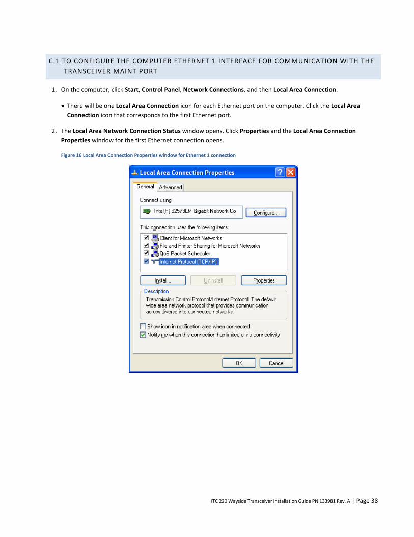
ITC 220 Wayside Transceiver Installation Guide PN 133981 Rev. A | Page 38
C.1 TO CONFIGURE THE COMPUTER ETHERNET 1 INTERFACE FOR COMMUNICATION WITH THE
TRANSCEIVER MAINT PORT
1. On the computer, click Start, Control Panel, Network Connections, and then Local Area Connection.
There will be one Local Area Connection icon for each Ethernet port on the computer. Click the Local Area
Connection icon that corresponds to the first Ethernet port.
2. The Local Area Network Connection Status window opens. Click Properties and the Local Area Connection
Properties window for the first Ethernet connection opens.
Figure 16 Local Area Connection Properties window for Ethernet 1 connection
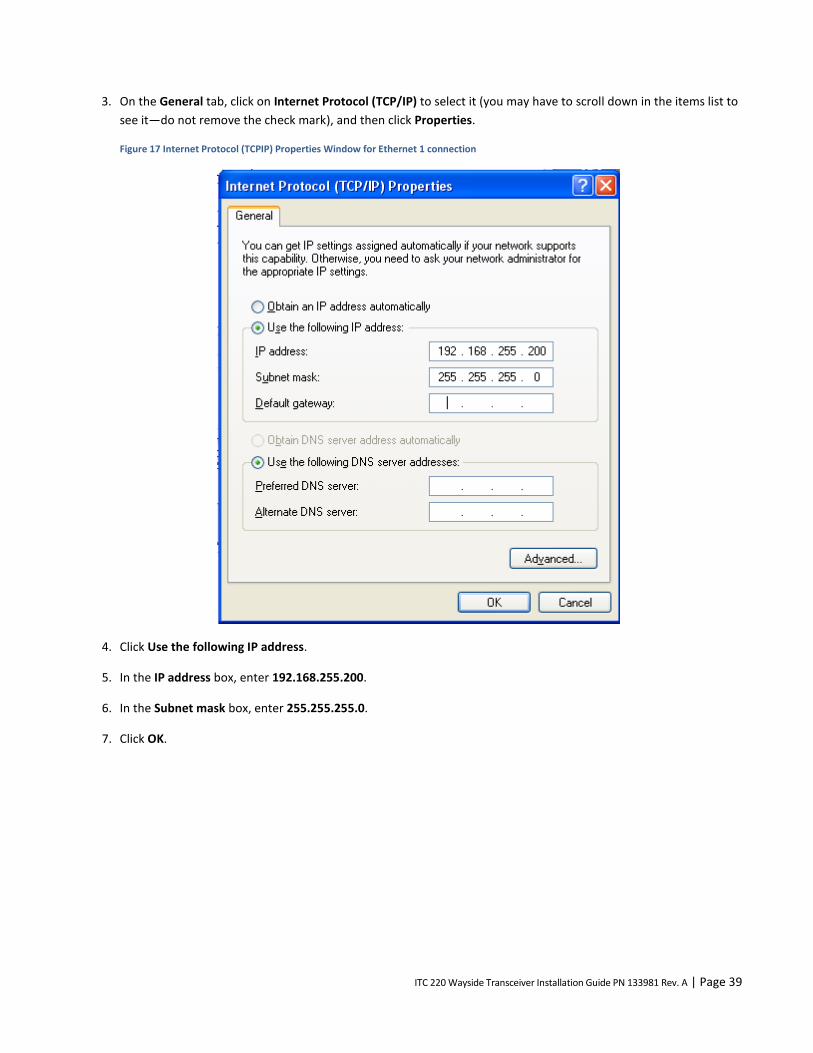
ITC 220 Wayside Transceiver Installation Guide PN 133981 Rev. A | Page 39
3. On the General tab, click on Internet Protocol (TCP/IP) to select it (you may have to scroll down in the items list to
see it—do not remove the check mark), and then click Properties.
Figure 17 Internet Protocol (TCPIP) Properties Window for Ethernet 1 connection
4. Click Use the following IP address.
5. In the IP address box, enter 192.168.255.200.
6. In the Subnet mask box, enter 255.255.255.0.
7. Click OK.

ITC 220 Wayside Transceiver Installation Guide PN 133981 Rev. A | Page 40
8. In XtermW, set the connection properties for the MAINT port connection as shown in the following figure.
Figure 18 XtermW Configure Port window with settings for MAINT port
Note TCP/IP Settings for Host on the MAINT port is configured for IP address 192.168.255.201.

ITC 220 Wayside Transceiver Installation Guide PN 133981 Rev. A | Page 41
C.2 TO CONFIGURE THE COMPUTER ETHERNET 2 INTERFACE FOR COMMUNICATION WITH THE
TRANSCEIVER LAN PORT
1. On the computer, click Start, Control Panel, Network Connections, and then Local Area Connection.
There will be one Local Area Connection icon for each Ethernet port on the computer. Click the Local Area
Connection icon that corresponds to the second Ethernet port.
2. The Local Area Network Connection Status window opens. Click Properties and the Local Area Connection
Properties window for the second Ethernet connection opens.
Figure 19 Local Area Connection Properties window for Ethernet 2 connection
3. On the General tab, click on Internet Protocol (TCP/IP) to select it (you may have to scroll down the items list to
see it—do not remove the check mark) and then click Properties.

ITC 220 Wayside Transceiver Installation Guide PN 133981 Rev. A | Page 42
Figure 20 Internet Protocol (TCP/IP) Properties window for Ethernet 2 connection
4. Click Use the following IP address.
5. In the IP address box, enter 10.255.255.200.
6. In the Subnet mask box, enter 255.255.255.0.
7. Click OK.
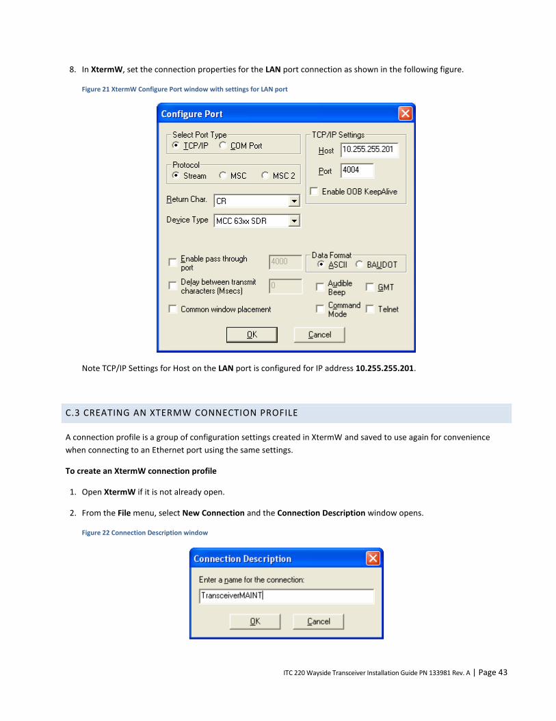
ITC 220 Wayside Transceiver Installation Guide PN 133981 Rev. A | Page 43
8. In XtermW, set the connection properties for the LAN port connection as shown in the following figure.
Figure 21 XtermW Configure Port window with settings for LAN port
Note TCP/IP Settings for Host on the LAN port is configured for IP address 10.255.255.201.
C.3 CREATING AN XTERMW CONNECTION PROFILE
A connection profile is a group of configuration settings created in XtermW and saved to use again for convenience
when connecting to an Ethernet port using the same settings.
To create an XtermW connection profile
1. Open XtermW if it is not already open.
2. From the File menu, select New Connection and the Connection Description window opens.
Figure 22 Connection Description window
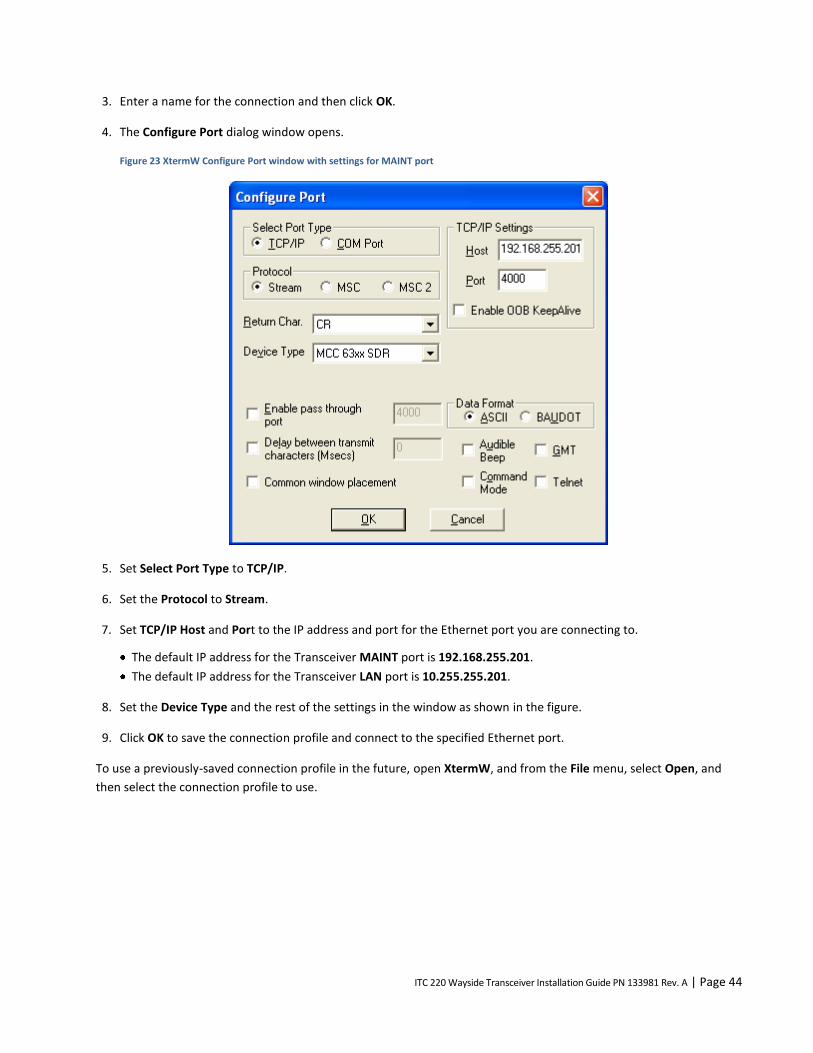
ITC 220 Wayside Transceiver Installation Guide PN 133981 Rev. A | Page 44
3. Enter a name for the connection and then click OK.
4. The Configure Port dialog window opens.
Figure 23 XtermW Configure Port window with settings for MAINT port
5. Set Select Port Type to TCP/IP.
6. Set the Protocol to Stream.
7. Set TCP/IP Host and Port to the IP address and port for the Ethernet port you are connecting to.
The default IP address for the Transceiver MAINT port is 192.168.255.201.
The default IP address for the Transceiver LAN port is 10.255.255.201.
8. Set the Device Type and the rest of the settings in the window as shown in the figure.
9. Click OK to save the connection profile and connect to the specified Ethernet port.
To use a previously-saved connection profile in the future, open XtermW, and from the File menu, select Open, and
then select the connection profile to use.
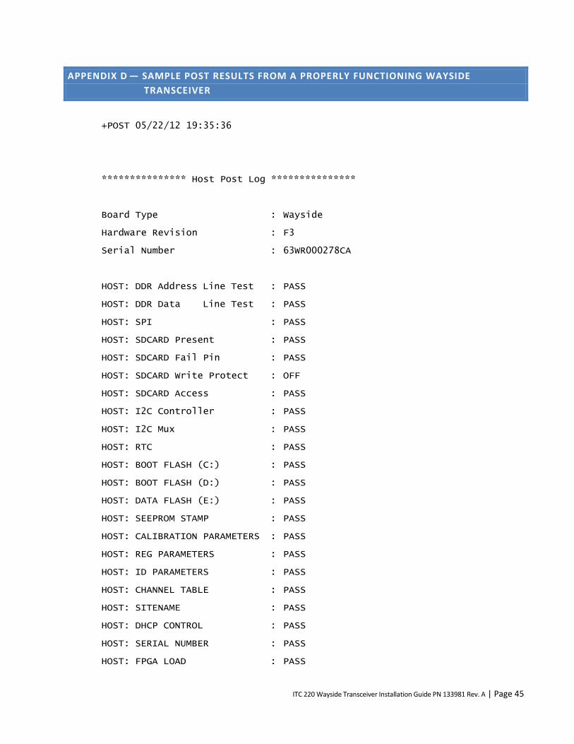
ITC 220 Wayside Transceiver Installation Guide PN 133981 Rev. A | Page 45
APPENDIX D — SAMPLE POST RESULTS FROM A PROPERLY FUNCTIONING WAYSIDE
TRANSCEIVER
+POST 05/22/12 19:35:36
*************** Host Post Log ***************
Board Type : Wayside
Hardware Revision : F3
Serial Number : 63WR000278CA
HOST: DDR Address Line Test : PASS
HOST: DDR Data Line Test : PASS
HOST: SPI : PASS
HOST: SDCARD Present : PASS
HOST: SDCARD Fail Pin : PASS
HOST: SDCARD Write Protect : OFF
HOST: SDCARD Access : PASS
HOST: I2C Controller : PASS
HOST: I2C Mux : PASS
HOST: RTC : PASS
HOST: BOOT FLASH (C:) : PASS
HOST: BOOT FLASH (D:) : PASS
HOST: DATA FLASH (E:) : PASS
HOST: SEEPROM STAMP : PASS
HOST: CALIBRATION PARAMETERS : PASS
HOST: REG PARAMETERS : PASS
HOST: ID PARAMETERS : PASS
HOST: CHANNEL TABLE : PASS
HOST: SITENAME : PASS
HOST: DHCP CONTROL : PASS
HOST: SERIAL NUMBER : PASS
HOST: FPGA LOAD : PASS
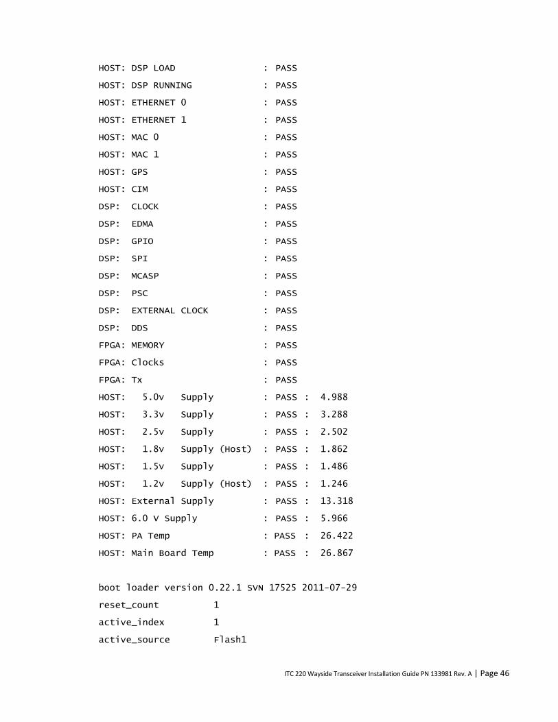
ITC 220 Wayside Transceiver Installation Guide PN 133981 Rev. A | Page 46
HOST: DSP LOAD : PASS
HOST: DSP RUNNING : PASS
HOST: ETHERNET 0 : PASS
HOST: ETHERNET 1 : PASS
HOST: MAC 0 : PASS
HOST: MAC 1 : PASS
HOST: GPS : PASS
HOST: CIM : PASS
DSP: CLOCK : PASS
DSP: EDMA : PASS
DSP: GPIO : PASS
DSP: SPI : PASS
DSP: MCASP : PASS
DSP: PSC : PASS
DSP: EXTERNAL CLOCK : PASS
DSP: DDS : PASS
FPGA: MEMORY : PASS
FPGA: Clocks : PASS
FPGA: Tx : PASS
HOST: 5.0v Supply : PASS : 4.988
HOST: 3.3v Supply : PASS : 3.288
HOST: 2.5v Supply : PASS : 2.502
HOST: 1.8v Supply (Host) : PASS : 1.862
HOST: 1.5v Supply : PASS : 1.486
HOST: 1.2v Supply (Host) : PASS : 1.246
HOST: External Supply : PASS : 13.318
HOST: 6.0 V Supply : PASS : 5.966
HOST: PA Temp : PASS : 26.422
HOST: Main Board Temp : PASS : 26.867
boot loader version 0.22.1 SVN 17525 2011-07-29
reset_count 1
active_index 1
active_source Flash1

ITC 220 Wayside Transceiver Installation Guide PN 133981 Rev. A | Page 47
active_user USER_BOOT
Inx Pri Stat Fail Lnch Name Notes Last Status
--- --- ---- ----- ----- -------------- ----- --------------
1 6 RDY 1 0 C:01011506.A17 ACTV Success

ITC 220 Wayside Transceiver Installation Guide PN 133981 Rev. A | Page 48
APPENDIX E — COMMAND SECURITY
User authentication is a way to identify yourself as someone who is allowed to change the radio’s configuration
settings.
User-authentication tasks consist of:
Logging on to a transceiver
Logging off from a transceiver
Changing your password
Replacing a forgotten password
Following sections describe each task in detail.
E.1 LOG ON TO THE TRANSCEIVER
The prerequisites for logging on to a transceiver are:
Recommended: an SD memory card with a configuration information module (CIM) script file installed in the
transceiver.
Note: You can log on without installing a CIM script. However, the transceiver will not transmit and it will reboot
after five minutes.
The transceiver has been powered on and has booted up successfully executing the CIM script.
A computer with Ethernet interfaces configured to communicate with the transceiver is connected to the
transceiver MAINT port.
The XtermW program is installed and running on the computer.
You have permission to enter commands that can change the configuration settings.
You can enter some commands that allow you to get the transceiver’s operational status only, such as SMS and
IPCONFIG (without parameters), without logging on.
Notes:
The login status defaults to logged-off when the transceiver boots up. If you want to log on again, you have to re-
enter your password after each reboot.
You can make an unlimited number of login attempts without being locked out of the transceiver.
The default password for the transceiver is mcc-6300.
You can have only one password at a time.
To log on to the transceiver:
1. On the computer, open XtermW if it is not already running.
2. Click Send, click Command, and then type:
LOGON,password
Where password is your current password.
ITC 220 Wayside Transceiver Installation Guide PN 133981 Rev. A | Page 49
3. Click OK or press Enter.
Note: If you enter the wrong password, you see the message “INCORRECT PASSWORD.” If you are already logged
on, you see the message “ALREADY LOGGED ON.”
E.2 LOG OFF FROM THE TRANSCEIVER
After you log on to a transceiver, it will log you off automatically if it does not detect any activity from you for 10
minutes. You can also log off manually at any time.
To log off from a radio:
1. On the computer, open XtermW if it is not already running.
2. Click Send, click Command, and then type:
LOGOFF
3. Click OK or press Enter.
E.3 CHANGE YOUR TRANSCEIVER PASSWORD
Changing your password from the default or a password you have been using to a new password is a good way to
improve security on the transceiver. If you are not sure when to change your password, check with your company’s
established security procedures.
The requirements for a password are:
Passwords can consist of any alphanumeric characters (a, b, c,…, 1, 2, 3,…), plus the dash (–) character, in any
combination. For example, a password can consist of all letters, all numbers, or a combination of letters and
numbers and dash characters.
Passwords must be 3 to 30 characters.
Passwords are not case sensitive.
To change your password:
1. Log on to the transceiver.
2. In XtermW , click Send, click Command, and then type:
NEWPASSWORD,oldpassword,newpassword,newpassword
Where:
oldpassword is your current password
newpassword is your new password you want to change to
3. Click OK or press Enter.

ITC 220 Wayside Transceiver Installation Guide PN 133981 Rev. A | Page 50
E.3.1 FORGET YOUR PASSWORD?
To recover from a forgotten password:
Ask an administrator who has permission to reset users’ passwords to the default password to reset your password
to the default.
Change your password from the default password to your own password. See E.3 Change Your Transceiver
Password.

ITC 220 Wayside Transceiver Installation Guide PN 133981 Rev. A | Page 51
APPENDIX F — COMMONLY USED DIAGNOSTIC COMMANDS
The following diagnostic commands provide information about the state of the transceiver, including current RF
connections and software version information. They can be used to collect information that may be useful in
determining why a radio connection is not performing as expected.
INICHECK
The INICHECK command checks the validity of the current transceiver configuration against the CIM (configuration
interface module) and optionally reconfigures the radio if the configuration is invalid. The CIM is a script file of
configuration commands with a signature contained in a removable SD card. When the CIM script is run, the radio is
configured by commands in the script and the CIM signature is stored in nonvolatile memory in the transceiver. When
a user invokes commands that reconfigure the transceiver, the CIM signature in the transceiver is invalidated. The
transceiver is reconfigured at startup if a CIM is found and the configuration is invalid. INICHECK allows a user to check
the configuration manually at any time.
Syntax:
INICHECK or INICHECK,script
Returns:
+OK on success, or
+Bad Parameter on failure.
LINKSTAT
The LINKSTAT command displays link statistics by link. On a remote transceiver (locomotive or wayside), it also
shows which Base Station Transceiver is currently selected. A minus-sign (–) to the left of the radio ID indicates that the
remote transceiver is currently attempting to connect to it. A caret (^) indicates that the remote transceiver is
connected to the Base transceiver. Below is an example of output from the LINKSTAT command on a Base Station
Transceiver.
+linkstat 08/23/11 00:42:52 NODE CHAN TYPE RXPKTS TXPKTS TXACKS BCAST BROADCST 000 SYSTM 0 0 0 0 CMNBDCST 000 SYSTM 0 0 0 0 r^00000500 v 127 SDR1 7 21 0 0
NODE CHAN TYPE RXMSGS TXMSGS RXSEGS TXSEGS BROADCST 000 SYSTM 0 0 0 0 CMNBDCST 000 SYSTM 0 0 0 0 r^00000500 v 127 SDR1 1 1 4 44
NODE CHAN TYPE BEACON WAIT DTRF STAT DIST DEG BROADCST 000 SYSTM 0 0000 0000 CMNBDCST 000 SYSTM 0 0000 0000 r^00000500 v 127 SDR1 0 0000 -099 0000 +
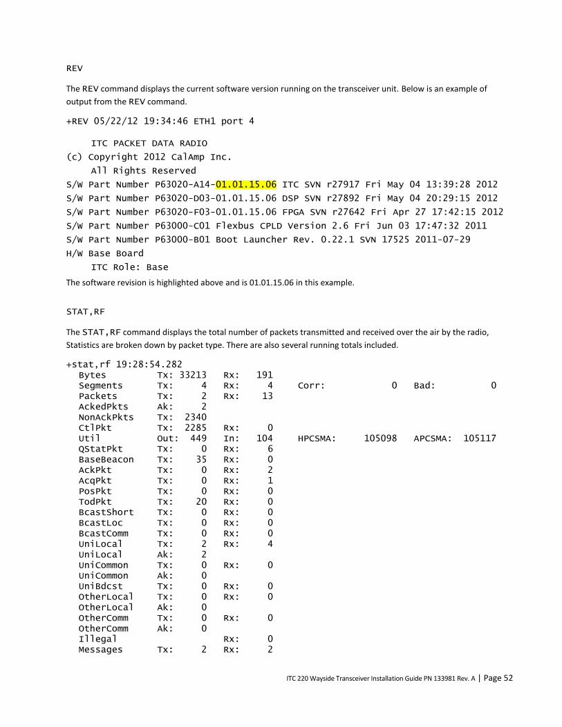
ITC 220 Wayside Transceiver Installation Guide PN 133981 Rev. A | Page 52
REV
The REV command displays the current software version running on the transceiver unit. Below is an example of
output from the REV command.
+REV 05/22/12 19:34:46 ETH1 port 4
ITC PACKET DATA RADIO
(c) Copyright 2012 CalAmp Inc.
All Rights Reserved
S/W Part Number P63020-A14-01.01.15.06 ITC SVN r27917 Fri May 04 13:39:28 2012
S/W Part Number P63020-D03-01.01.15.06 DSP SVN r27892 Fri May 04 20:29:15 2012
S/W Part Number P63020-F03-01.01.15.06 FPGA SVN r27642 Fri Apr 27 17:42:15 2012
S/W Part Number P63000-C01 Flexbus CPLD Version 2.6 Fri Jun 03 17:47:32 2011
S/W Part Number P63000-B01 Boot Launcher Rev. 0.22.1 SVN 17525 2011-07-29
H/W Base Board
ITC Role: Base
The software revision is highlighted above and is 01.01.15.06 in this example.
STAT,RF
The STAT,RF command displays the total number of packets transmitted and received over the air by the radio,
Statistics are broken down by packet type. There are also several running totals included.
+stat,rf 19:28:54.282 Bytes Tx: 33213 Rx: 191 Segments Tx: 4 Rx: 4 Corr: 0 Bad: 0 Packets Tx: 2 Rx: 13 AckedPkts Ak: 2 NonAckPkts Tx: 2340 CtlPkt Tx: 2285 Rx: 0 Util Out: 449 In: 104 HPCSMA: 105098 APCSMA: 105117 QStatPkt Tx: 0 Rx: 6 BaseBeacon Tx: 35 Rx: 0 AckPkt Tx: 0 Rx: 2 AcqPkt Tx: 0 Rx: 1 PosPkt Tx: 0 Rx: 0 TodPkt Tx: 20 Rx: 0 BcastShort Tx: 0 Rx: 0 BcastLoc Tx: 0 Rx: 0 BcastComm Tx: 0 Rx: 0 UniLocal Tx: 2 Rx: 4 UniLocal Ak: 2 UniCommon Tx: 0 Rx: 0 UniCommon Ak: 0 UniBdcst Tx: 0 Rx: 0 OtherLocal Tx: 0 Rx: 0 OtherLocal Ak: 0 OtherComm Tx: 0 Rx: 0 OtherComm Ak: 0 Illegal Rx: 0 Messages Tx: 2 Rx: 2
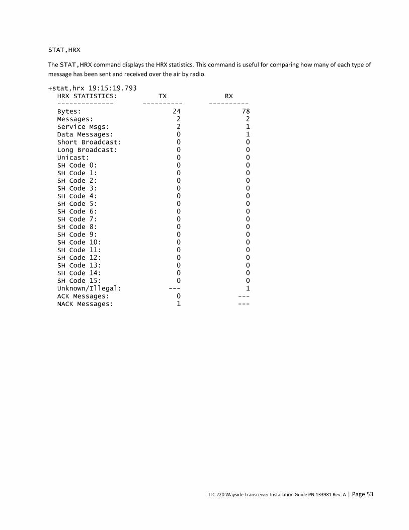
ITC 220 Wayside Transceiver Installation Guide PN 133981 Rev. A | Page 53
STAT,HRX
The STAT,HRX command displays the HRX statistics. This command is useful for comparing how many of each type of
message has been sent and received over the air by radio.
+stat,hrx 19:15:19.793 HRX STATISTICS: TX RX -------------- ---------- ---------- Bytes: 24 78 Messages: 2 2 Service Msgs: 2 1 Data Messages: 0 1 Short Broadcast: 0 0 Long Broadcast: 0 0 Unicast: 0 0 SH Code 0: 0 0 SH Code 1: 0 0 SH Code 2: 0 0 SH Code 3: 0 0 SH Code 4: 0 0 SH Code 5: 0 0 SH Code 6: 0 0 SH Code 7: 0 0 SH Code 8: 0 0 SH Code 9: 0 0 SH Code 10: 0 0 SH Code 11: 0 0 SH Code 12: 0 0 SH Code 13: 0 0 SH Code 14: 0 0 SH Code 15: 0 0 Unknown/Illegal: --- 1 ACK Messages: 0 --- NACK Messages: 1 ---

ITC 220 Wayside Transceiver Installation Guide PN 133981 Rev. A | Page 54
APPENDIX G — TRANSCEIVER TEST AND ADJUSTMENT PROCEDURES
Some of the procedures you perform to solve a problem consist of a single, simple step, such as tightening a cable
connection to fix a transmission problem. But several procedures consist of multiple steps. Multiple-step procedures
are described in this section.
G.1 REQUIRED EQUIPMENT
The tests and adjustments described in this section require service personnel to have equipment listed in the Required
Equipment section, as well as the skill and knowledge to use them.
Caution – Applying an incorrect voltage outside the rated voltage range of a Wayside Transceiver damage it.
Confirm the voltage rating of the Wayside Transceiver and power supply before applying power.
Table 4 Wayside Transceiver input power parameters
Parameter Value
Nominal DC Power Input Voltage 13.6 VDC
Operational range 10.9-15.5 VDC (+14%/–20%)
Damage limit 17 VDC
Current draw (while transmitting rated power) 7.5 A – typical while transmitting into 50 Ohm load, 10 A maximum
G.2 PUT A TRACE ON A FEATURE
A trace enables you to monitor and log a specific activity of an ITC radio transceiver. Examples of traceable activities are
port activity, RF link activity, and forward-error-correction (FEC) activity. You can save traces in a log file.
Note: Heavy tracing can affect radio performance. Do not leave traces running at the site.
Table 5 Brief descriptions of available trace features
Feature Description of traced data and notes
0-16 All activity on a selected I/O port
CLASC Class C time and location messages
CLASD Information about Class D messages
DEBUG Variety of diagnostic data on ITC RADIO activity
DLOG Replaces DSP_CMD,LOG,on/off and displays the DSP status log
DSP Trace messages transferred from the DSP via the HPI interface
ETH Information about the Ethernet connection status
EVENT Event activity
GPS Activity in the GPS protocol device driver

ITC 220 Wayside Transceiver Installation Guide PN 133981 Rev. A | Page 55
Feature Description of traced data and notes
HRX Information about the HRX messages
IDLE Transmitted and received Base Beacons
ISMP Information about ISMP messages
NOISE Sampled (every second) and averaged (every five minutes) RF noise levels
RF Activity on the RF link
RSSI Signal strength indicators
RX Hex dump of data being received through the RF receivers
TX Hex dump of transmit date being sent to the RF transmitter
To trace an activity:
1. Use Category 5 or better Ethernet cable to connect the correct computer Ethernet port to the transceiver’s MAINT
port.
2. The Ethernet port must be configured to communicate with the MAINT port. See C.1 To Configure the Computer
Ethernet 1 Interface for Communication with the Transceiver MAINT Port.
3. On the computer, open the XtermW application.
4. Specify the transceiver port you want to communicate with: Click Send, click Command, and then type:
TRACE,port,maint
where:
TRACE is the trace command,
port is a subcommand, and
Maint refers to the MAINT port.
5. Click OK.
6. Select the trace feature and output destination: Click Send, click Command, and then type:
TRACE,level,feature,destination
where:
TRACE is the trace command,
level is a number from 0 to 7,
feature is the name of the feature you want to trace, and
destination is the location of the trace output, which can be port, file, or both. If you do not enter a
destination, the trace output is sent to the port only.
7. Click OK.

ITC 220 Wayside Transceiver Installation Guide PN 133981 Rev. A | Page 56
To suspend a trace:
1. In XtermW, click Send, Click Command, and then type:
TRACE,SUSPEND
2. Click OK.
To resume a trace:
1. In XtermW, click Send, click Command, and then type:
TRACE,RESUME
2. Click OK.
To stop a trace:
1. In XtermW, click Send, click Command, and then type:
TRACE,OFF
2. Click OK.
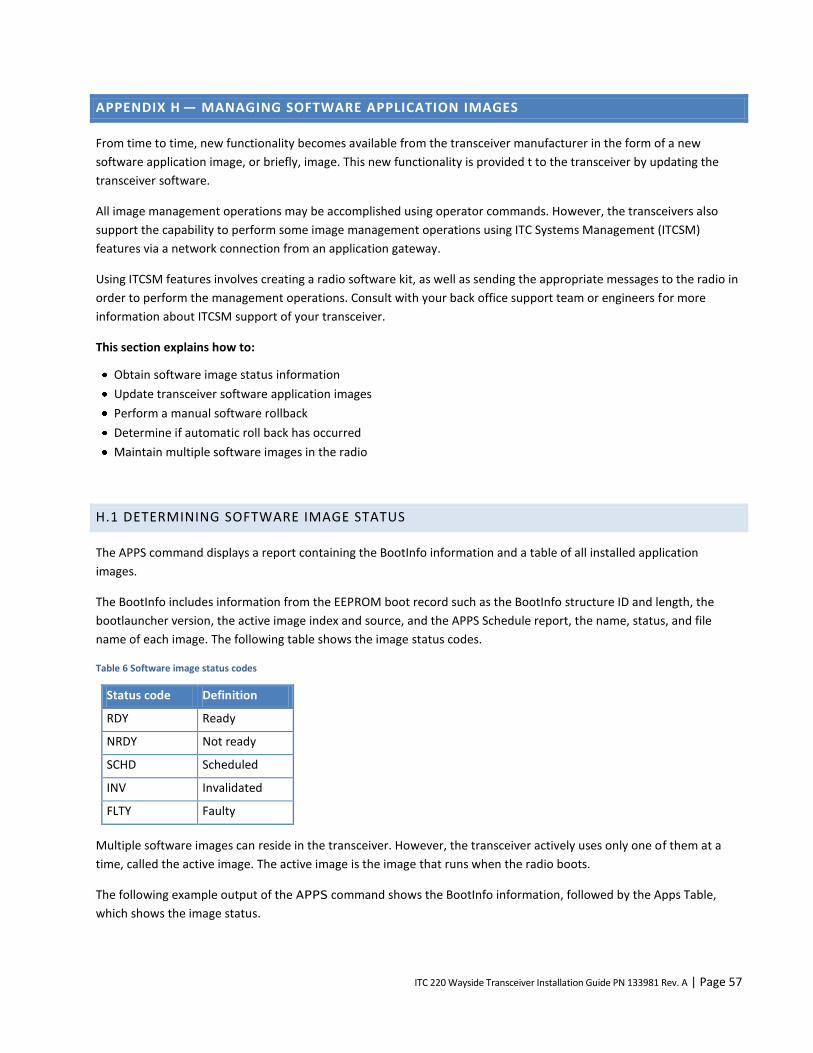
ITC 220 Wayside Transceiver Installation Guide PN 133981 Rev. A | Page 57
APPENDIX H — MANAGING SOFTWARE APPLICATION IMAGES
From time to time, new functionality becomes available from the transceiver manufacturer in the form of a new
software application image, or briefly, image. This new functionality is provided t to the transceiver by updating the
transceiver software.
All image management operations may be accomplished using operator commands. However, the transceivers also
support the capability to perform some image management operations using ITC Systems Management (ITCSM)
features via a network connection from an application gateway.
Using ITCSM features involves creating a radio software kit, as well as sending the appropriate messages to the radio in
order to perform the management operations. Consult with your back office support team or engineers for more
information about ITCSM support of your transceiver.
This section explains how to:
Obtain software image status information
Update transceiver software application images
Perform a manual software rollback
Determine if automatic roll back has occurred
Maintain multiple software images in the radio
H.1 DETERMINING SOFTWARE IMAGE STATUS
The APPS command displays a report containing the BootInfo information and a table of all installed application
images.
The BootInfo includes information from the EEPROM boot record such as the BootInfo structure ID and length, the
bootlauncher version, the active image index and source, and the APPS Schedule report, the name, status, and file
name of each image. The following table shows the image status codes.
Table 6 Software image status codes
Status code Definition
RDY Ready
NRDY Not ready
SCHD Scheduled
INV Invalidated
FLTY Faulty
Multiple software images can reside in the transceiver. However, the transceiver actively uses only one of them at a
time, called the active image. The active image is the image that runs when the radio boots.
The following example output of the APPS command shows the BootInfo information, followed by the Apps Table,
which shows the image status.
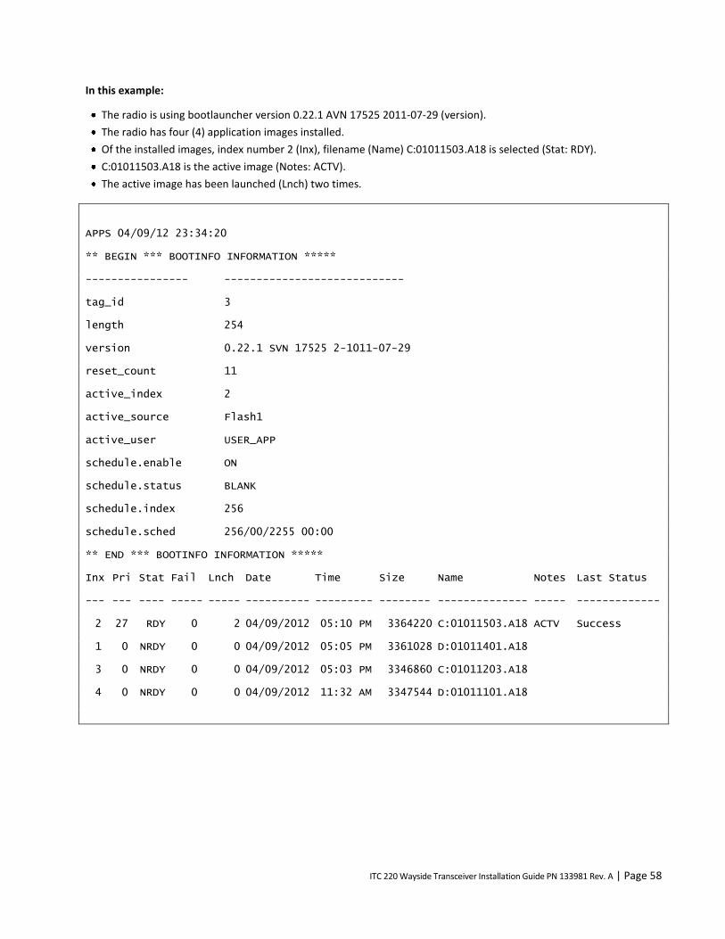
ITC 220 Wayside Transceiver Installation Guide PN 133981 Rev. A | Page 58
In this example:
The radio is using bootlauncher version 0.22.1 AVN 17525 2011-07-29 (version).
The radio has four (4) application images installed.
Of the installed images, index number 2 (Inx), filename (Name) C:01011503.A18 is selected (Stat: RDY).
C:01011503.A18 is the active image (Notes: ACTV).
The active image has been launched (Lnch) two times.
APPS 04/09/12 23:34:20
** BEGIN *** BOOTINFO INFORMATION *****
---------------- ----------------------------
tag_id 3
length 254
version 0.22.1 SVN 17525 2-1011-07-29
reset_count 11
active_index 2
active_source Flash1
active_user USER_APP
schedule.enable ON
schedule.status BLANK
schedule.index 256
schedule.sched 256/00/2255 00:00
** END *** BOOTINFO INFORMATION *****
Inx Pri Stat Fail Lnch Date Time Size Name Notes Last Status
--- --- ---- ----- ----- ---------- --------- -------- -------------- ----- -------------
2 27 RDY 0 2 04/09/2012 05:10 PM 3364220 C:01011503.A18 ACTV Success
1 0 NRDY 0 0 04/09/2012 05:05 PM 3361028 D:01011401.A18
3 0 NRDY 0 0 04/09/2012 05:03 PM 3346860 C:01011203.A18
4 0 NRDY 0 0 04/09/2012 11:32 AM 3347544 D:01011101.A18

ITC 220 Wayside Transceiver Installation Guide PN 133981 Rev. A | Page 59
H.2 UPDATING SOFTWARE IMAGES
Updating the software means loading/installing the software image, selecting it to be active, and then
activating/running it.
H.2.1 UPDATING TRANSCEIVER SOFTWARE USING THE COMMAND LINE
To update transceiver software:
1. Ensure that the new software image file is located on a computer drive accessible to the computer on which you
run XtermW.
2. Ensure that the destination file name is unique in the radio Apps table. Prior to performing the software update,
check the names of existing files on the transceiver by using the APPS command to display a list of all installed
application images.
3. Ensure that there is adequate space available on the non-active drive to store the file. If not, delete an unneeded
image from the non-active drive using the APPS,DELETE command. (If the image to be deleted is RDY or NRDY,
it must first be declared invalid using the APPS,INVALIDATE command.)
4. Establish a connection from XtermW to the transceiver using a connection profile that was created with the Device
Type set to MCC 63xx SDR.
Note: The connection profile Device Type determines the kinds of menu options displayed, so it is important to
use the proper connection profile.
5. To download the software image, on the Send menu, select 63xx File Download. You will see a dialog window like
the following:
6. Under File Type, select App.
7. Click Browse, then locate and select the software image file.

ITC 220 Wayside Transceiver Installation Guide PN 133981 Rev. A | Page 60
8. After you select the software image file:
The Destination File Name field is automatically populated with a file name derived from the selected image file
name.
Ensure that the destination file name meets the 8.3 filename requirements, meaning that the filename can have
at most eight alphanumeric characters, followed by a period and extension of at most three alphanumeric
characters. A few special characters are also allowed (namely, ! # $ % & ' ( ) - @ ^ _ ` { } and ~). Alphabetical
characters are treated as case-insensitive.
9. To select this image immediately after it is downloaded, select the Select check box.
When you select the Select check box, XtermW automatically executes the APPS,SELECT,image-file
command after the software image is downloaded. It also causes XtermW to enable the Boot check box.
The Boot check box is available only when you select the Select check box. When you select the Boot check box,
XtermW automatically executes the BOOT command after the APPS,SELECT,image-file command, causing
the newly downloaded image to become the active image after a reboot.
10. To execute a synchronized software update at a future time, select the Schedule check box. Choose the desired
date and time in the pop-up window, and then click OK.
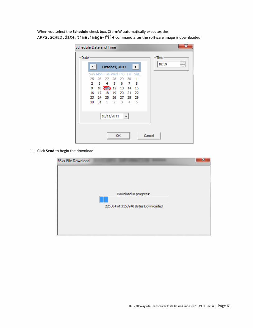
ITC 220 Wayside Transceiver Installation Guide PN 133981 Rev. A | Page 61
When you select the Schedule check box, XtermW automatically executes the
APPS,SCHED,date,time,image-file command after the software image is downloaded.
11. Click Send to begin the download.

ITC 220 Wayside Transceiver Installation Guide PN 133981 Rev. A | Page 62
12. After the installation finishes, you see the following text in the XtermW console window.
13. Execute the APPS command and then observe the following:
If the Select and Boot check boxes were selected, the downloaded software image will be listed as ACTV (active
image) after the reboot.
If the Select check box was cleared, the downloaded software image will be listed with the status of NRDY.
If the Select check box was selected, the downloaded software image will be listed in the top row of the Apps
table with the highest priority and a status of RDY.
If the Schedule check box was selected, the downloaded software image will be listed with a status of SCHD. The
APPS,SCHED command displays a report of the software update schedule.

ITC 220 Wayside Transceiver Installation Guide PN 133981 Rev. A | Page 63
H.3 ROLLING BACK AN IMAGE
H.3.1 HOW AUTOMATIC ROLLBACK OCCURS
Each time the active image fails to execute for longer than four (4) minutes due to unexpected power-cycles (the
application fails or there is a power interruption), the failure counter of that image is incremented. When the active
image executes longer than four (4) minutes, the failure counter of that image is reset.
In rare instances when the active image failure counter exceeds the failure counter threshold, the bootlauncher
executes the following logic at power up:
Find all other images in the Apps table that have a RDY status.
If any RDY status images are found in the Apps table, then:
a. Select the image with the highest priority as the new active image.
b. Mark the previous active image as faulty (FLTY).
c. Launch the new active image. Automatic rollback has occurred. The previous image will display a FLTY status in the
Apps report.
Else, if no other RDY status images are found then:
a. Update the failure counter of the current active image even if the failure counter exceeds the failure counter
threshold.
b. Keep the current active image as RDY.
c. Retry launching the current active image.
H.3.2 DETERMINING IF AUTOMATIC ROLLBACK OCCURRED
View the Apps report to determine if automatic rollback occurred.
To check if automatic rollback occurred
Execute the APPS command.
Observe the status column of the Apps report:
The previous active image will be listed with a status of FLTY and its failure counter will indicate a value greater than
the failure counter threshold.
Since the previous active image status is now FLTY, it is no longer manually selectable by the APPS,SELECT
command, or by the Automatic rollback feature.
Note: You can manually delete the FLTY image by using the APPS,DELETE command. The FLTY image may also be
automatically deleted when disk space is needed for new image downloads.

ITC 220 Wayside Transceiver Installation Guide PN 133981 Rev. A | Page 64
H.3.3 ROLLING BACK AN IMAGE VIA THE COMMAND LINE: APPS
You can manually roll back software when there are multiple software images installed in the transceiver.
To manually roll back a software image:
Execute the APPS command.
View the list of installed images.
In the sample APPS command output below, the following images are installed: C:01011503.A18, D:01011401.A18, and
C:01011203.A18, where C:01011503.A18 is the active image.
Inx Pri Stat Fail Lnch Date Time Size Name Notes Last Status
--- --- ---- ----- ----- ---------- --------- -------- -------------- ----- -------------
3 27 RDY 1 2 04/09/2012 05:10 PM 3364220 C:01011503.A18 ACTV Success
2 26 RDY 0 2 04/09/2012 05:05 PM 3361028 D:01011401.A18 Success
1 25 RDY 0 0 04/09/2012 05:03 PM 3346860 C:01011203.A18
If required, setup a CIM script association for each image to ensure that the proper CIM script executes when a
particular image becomes the active image. Use the INISELECT command.
To manually roll back to D:01011401.A18, use the following commands:
APPS,SELECT,D:01011401.A18
BOOT
After the reboot, the Apps table should report D:01011401.A18 as the active image. Rollback is complete.
Inx Pri Stat Fail Lnch Date Time Size Name Notes Last Status
--- --- ---- ----- ----- ---------- --------- -------- -------------- ----- -------------
2 28 RDY 1 2 04/09/2012 05:05 PM 3361028 D:01011401.A18 ACTV Success
3 27 RDY 0 2 04/09/2012 05:10 PM 3364420 C:01011503.A18 Success
1 25 RDY 0 0 04/09/2012 05:03 PM 3346860 D:01011203.A18
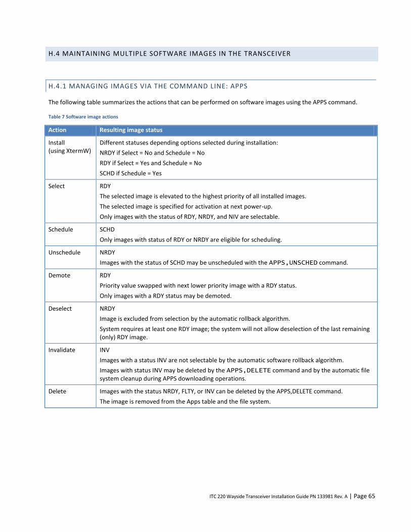
ITC 220 Wayside Transceiver Installation Guide PN 133981 Rev. A | Page 65
H.4 MAINTAINING MULTIPLE SOFTWARE IMAGES IN THE TRANSCEIVER
H.4.1 MANAGING IMAGES VIA THE COMMAND LINE: APPS
The following table summarizes the actions that can be performed on software images using the APPS command.
Table 7 Software image actions
Action Resulting image status
Install (using XtermW)
Different statuses depending options selected during installation:
NRDY if Select = No and Schedule = No
RDY if Select = Yes and Schedule = No
SCHD if Schedule = Yes
Select RDY
The selected image is elevated to the highest priority of all installed images.
The selected image is specified for activation at next power-up.
Only images with the status of RDY, NRDY, and NIV are selectable.
Schedule SCHD
Only images with status of RDY or NRDY are eligible for scheduling.
Unschedule NRDY
Images with the status of SCHD may be unscheduled with the APPS,UNSCHED command.
Demote RDY
Priority value swapped with next lower priority image with a RDY status.
Only images with a RDY status may be demoted.
Deselect NRDY
Image is excluded from selection by the automatic rollback algorithm.
System requires at least one RDY image; the system will not allow deselection of the last remaining (only) RDY image.
Invalidate INV
Images with a status INV are not selectable by the automatic software rollback algorithm.
Images with status INV may be deleted by the APPS,DELETE command and by the automatic file system cleanup during APPS downloading operations.
Delete Images with the status NRDY, FLTY, or INV can be deleted by the APPS,DELETE command.
The image is removed from the Apps table and the file system.
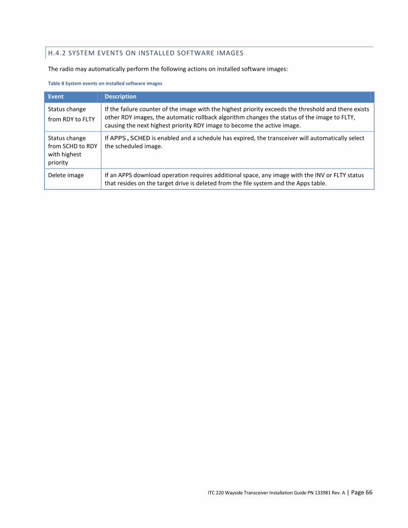
ITC 220 Wayside Transceiver Installation Guide PN 133981 Rev. A | Page 66
H.4.2 SYSTEM EVENTS ON INSTALLED SOFTWARE IMAGES
The radio may automatically perform the following actions on installed software images:
Table 8 System events on installed software images
Event Description
Status change
from RDY to FLTY
If the failure counter of the image with the highest priority exceeds the threshold and there exists other RDY images, the automatic rollback algorithm changes the status of the image to FLTY, causing the next highest priority RDY image to become the active image.
Status change from SCHD to RDY with highest priority
If APPS,SCHED is enabled and a schedule has expired, the transceiver will automatically select the scheduled image.
Delete image If an APPS download operation requires additional space, any image with the INV or FLTY status that resides on the target drive is deleted from the file system and the Apps table.

ITC 220 Wayside Transceiver Installation Guide PN 133981 Rev. A | Page 67
ABOUT CALAMP
CalAmp is a leading provider of wireless communications products that enable anytime/anywhere access to critical
information, data, and entertainment content. With comprehensive capabilities ranging from product design and
development through volume production, CalAmp delivers cost-effective high quality solutions to a broad array of
customers and end markets. CalAmp is the leading supplier of Direct Broadcast Satellite (DBS) outdoor customer
premise equipment to the U.S. satellite television market. The Company also provides wireless data communication
solutions for the telemetry and asset tracking markets, private wireless networks, railroad Positive Train Control (PTC)
radio transceivers, public safety communications and critical infrastructure and process control applications. For
additional information, please visit the Company’s website at www.calamp.com.