itatech activity group support - ita-aites
TRANSCRIPT

ITAtech Activity GroupSupport
ITAtech RepoRT n°9 / MARCH 2018n° ISBn: 978-2-9701122-3-5
Guideline For Good Practice oF Fibre reinForced Precast seGment - Vol. 2 : Production asPects

ITAtech Report n°9 - Guideline For Good Practice oF Fibre reinForced Precast seGment - N°ISBN: 978-2-9701122-3-5 / MARCH 2018Layout : Longrine – Avignon – France – www.longrine.fr
The International Tunnelling and Underground Space Association/Association Internationale des Tunnels et de l’Espace Souterrain (ITA/AITES) publishes this report to, in accordance with its statutes, facilitate the exchange of information, in order: to encourage planning of the subsurface for the benefit of the public, environment and sustainable development to promote advances in planning, design, construction, maintenance and safety of tunnels and underground space, by bringing together information thereon and by studying questions related thereto. This report has been prepared by professionals with expertise within the actual subjects. The opinions and statements are based on sources believed to be reliable and in good faith. However, ITA/AITES accepts no responsibility or liability whatsoever with regard to the material published in this report. This material is: information of a general nature only which is not intended to address the specific circumstances of any particular individual or entity; not necessarily comprehensive, complete, accurate or up to date; This material is not professional or legal advice (if you need specific advice, you should always consult a suitably qualified professional).

FoRewoRd
When producing Volume 1 of this guidance document the authors decided to initially focus on the design aspects of fibre reinforced concrete segmental tunnel linings, recognising that both segment design and production constitute equally important aspects for the success of tunnels lined with precast fibre reinforced concrete segments. Volume 2 therefore concentrates on the production of segments and the associated quality control.
The advantages of using Fibre Reinforced Concrete for segments are particularly eminent in the production phase, as the absence or reduction of bar reinforcement typically results in program and cost savings, and in the reduction of risk associated with the manufacture and installation of reinforcement cages.
As in Volume 1, the aim of this document is to present the common understanding of designers, manufacturers and users of fibre reinforced concrete segments of what constitutes good practice in this field of engineering. The document should be read in combination with Volume 1, which contains useful information on elementary properties of fibre reinforced concrete.ITAtech and the sub activity group welcomes all feedback on this document and will incorporate the user experience with the document in the course of future new editions.
ITAtech Activity GroupSupport
Guideline For Good Practice oF Fibre reinForced Precast seGment - Vol. 2 : Production asPects

4 GuIdelIne FoR Good pRACTICe oF FIBRe ReInFoRCed pReCAST SeGMenT – VoluMe 2 : pRoduCTIon ASpeCTS
>> table oF contents
FoRewoRd ............................................................................................................................................3
AuTHoRS ................................................................................................................................................6
noTATIon ...............................................................................................................................................7
1. pRoduCTIon .....................................................................................................................................8
1.1 FACTORY AND PRODUCTION SYSTEM .....................................................................................8
1.1.1 Static Moulds .......................................................................................................................8
1.1.2 Carousels ..........................................................................................................................10
1.1.3 Production - summary .........................................................................................................12
1.2 MOULDS AND VIBRATION......................................................................................................12
2. ConCReTe MIX deSIGn .................................................................................................................16
2.1. INTRODUCTION ...................................................................................................................16
2.2. CONSTITUENT MATERIALS ...................................................................................................16
2.2.1. Cementitious Materials ........................................................................................................16
2.2.2. Aggregates .......................................................................................................................16
2.2.3. Admixtures .......................................................................................................................16
2.2.4. Water ...............................................................................................................................16
2.2.5. Fibres ..............................................................................................................................16
2.3 CURING ..............................................................................................................................17
2.4 COORDINATION OF STRUCTURAL DESIGN AND MIX DESIGN ....................................................18
2.4.1. Handling and Transportation ................................................................................................18
2.4.2. Storage ............................................................................................................................18
2.4.3. Compressive Strength.........................................................................................................19
2.4.4. Tensile and Flexural Tensile Strengths.....................................................................................19
2.4.5. Tolerances ........................................................................................................................19

5ITAtech ACTIVITY GRoup - SuppoRT
>> table oF contents
3. QuAlITY ConTRol FoR pReCAST SeGMenTS .........................................................................20
3.1. INTRODUCTION ...................................................................................................................20
3.2. INITIAL TESTING ..................................................................................................................20
3.3. PRODUCTION CONTROL ......................................................................................................20
3.4. QUALITY CONTROL PLAN ....................................................................................................20
3.4.1. Conformity testing ..............................................................................................................21
3.4.2. Control of the constituent materials .......................................................................................21
3.4.3. Control of equipment ..........................................................................................................21
3.4.4. Conformity of concrete ........................................................................................................22
3.4.5. Fibres ..............................................................................................................................22
3.4.6. Geometry of Segments .......................................................................................................22
3.4.7. Marking of Segments ..........................................................................................................22
3.5. ASSESSMENT OF CONCRETE PROPERTIES ...........................................................................22
3.5.1. Initial tests.........................................................................................................................23
3.5.2. Tests during production .......................................................................................................25
3.6. NON CONFORMING SEGMENTS ...........................................................................................25
AnneXe 1 ..............................................................................................................................................26
PRECISION 3D MEASUREMENT OF MOULDS AND SEGMENTS .......................................................26
PERFORMANCE SPECIFICATION .................................................................................................26
TOLERANCES ...........................................................................................................................26
AnneXe 2 ..............................................................................................................................................32
CE MARKING ............................................................................................................................32

6 GuIdelIne FoR Good pRACTICe oF FIBRe ReInFoRCed pReCAST SeGMenT – VoluMe 2 : pRoduCTIon ASpeCTS
>> author list
Main authors
Christoph EBERLE (chairman)
Charles ALLEN
Nod CLARKE-HACKSTON
Holger KUPFER
Benoit de RIVAZ
Activity Group members
Trevor ATKINSON
Angel DEL AMO
Simon EVANS
Davide FABRI
Duzic IVICA
M. KOMPATSCHER
Luca MANCINELLI
Mario MANSER
Garry MARTIN
Wilhelm NELL
Guner PINAR
Phil QUELCH
Bruno ROSSI
Ernesto SCHÜMPERLI
Carlo SILVESTRI
Kazuto TABARA
Alun THOMAS
Grover VARGAS
Ralf WINTERBERG
Stephen WHITHAM
peer Reviewers
Rolando JUSTA CAMARA
Luis PINILLOS LORENZANA
Paolo ROMUALDI
Company
Mott MacDonald
OTB
VMT
Herrenknecht Formwork
Bekaert – Maccaferri Underground Solutions
Propex
Aldea Services
Propex
Lombardi
Halfen GmbH
Hagerbach
Lombardi
Contec Fiber AG
Elasto Plastic Concrete
KrampeHarex
Kordsa Global
CH2M Hill
Bekaert – Maccaferri Underground Solutions
Sika
Lombardi
Denka
Minova
Propex
Elasto Plastic Concrete
Ramboll
Acciona
Mott MacDonald
Salini Impregilo

7ITAtech ACTIVITY GRoup - SuppoRT
CMOD Crack Mouth Opening Displacement
fcm Concrete Mean Compressive Strength
fck Concrete Characteristic Compressive Strength
fctm Concrete Mean Tensile Strength
fctk Concrete Characteristic Tensile Strength
fcd Concrete Design Compressive Strength
fL,k Characteristic limit of Proportionality stress of FRC beam
fRi Residual flexural strength of FRC beam
fRim Mean Residual strength of FRC beam
fRik Characteristic Residual strength of FRC beam
fFts FRC tensile strength at SLS (Model Code 2010)
fFtu FRC tensile strength at ULS (Model Code 2010)
FEA Finite Element Analysis
Fib Federation International du Beton
FRC Fibre Reinforced Concrete
GGBS Ground granulated blast furnace slag
kn coefficient - statistical
K coefficient
LOP Limit of Proportionality
PFA Pulverised fuel ash
RILEM Reunion Internationale des Laboratoire d’ Essais Materiaux
SLS Serviceability Limit State
Sn Standard Deviation
ULS Ultimate Limit State (states associated with collapse of structural failure)
Vx Coefficient of variation
wk Characteristic crack width
>> notation

8 GuIdelIne FoR Good pRACTICe oF FIBRe ReInFoRCed pReCAST SeGMenT – VoluMe 2 : pRoduCTIon ASpeCTS
1 >> Production
1.1. FACToRY And pRoduCTIon SYSTeM
The manufacture of precast concrete segments for tunnel lining is required to take place in a factory environment, in order that the different sequences of manufacturing may be carried out in a logical, pre-ordered, systematic process. The factory comprises of the production line(s), and storage areas.
Segments may be manufactured in an existing precast concrete factory or in a factory that has been specially set up for the tunnelling project, either on or off site. Quality control and inspection regimes specific to segment production are to be defined in either case. Basically, there are two methods of segment production – by using static moulds or a carousel system.
1.1.1. Static Moulds
In this system, a number of segment moulds are set up inside the factory shed in static positions, bolted to the floor slab through rubber pads. Concrete is delivered directly to the moulds by an overhead bucket system or by truck mixers or other wheeled delivery vehicles.
Static mould systems often incorporate electrical curing resistances or steam pipes in channels within the factory floor in order that the moulds may be covered with thermal blankets at the end of the casting sequence and dry heat or steam cured to give sufficient strength for demoulding of the segments the following day, or within several hours.Generally speaking, static mould systems will produce one set of cast segments from the moulds each 24 hours. Projects in hot climates or that use steam curing and/or heated fresh concrete can achieve multiple castings per mould per 24 hours.
Figure 1 : Static mould system in a segment factory.
Figure 1b : Overhead bucket concrete delivery for static mould system.
Figure 1c : Static moulds covered with thermal blankets.
Figure 1a : Concrete delivery by concrete mixer for static mould system.

9ITAtech ACTIVITY GRoup - SuppoRT
1 >> Production
1.1.2. Carousels
In this production system, the concrete is placed in the moulds at a fixed casting station and the moulds are delivered to the casting station on a motorised circuit known as a carousel.
The carousel circuit contains a number of full ring sets of moulds and the manufacturing is designed as an industrialised process comprising several workstations that each mould passes through on its journey around the carousel before being transferred into a heat curing chamber for a period of several hours. The process is typically controlled through programmable logic controllers (PLC) which can be integrated into the quality management system for segment manufacture, allowing a higher level of control and documentation compared to the static mould setup.
At the workstations the following processes are carried out :
Figure 3 : Plan of a typical carousel system.
Figure 2 : A typical carousel system.

10 GuIdelIne FoR Good pRACTICe oF FIBRe ReInFoRCed pReCAST SeGMenT – VoluMe 2 : pRoduCTIon ASpeCTS
1 >> Production
1 >> Demoulding of the segment.
2 >> Cleaning of the mould.
3 >> Preparing the mould for concreting. b. Placement of reinforcement cages, if required (not shown) and closing of the mould.
3 >> Preparing the mould for concreting.a. Placement of inserts, application of debonding agent, and greasing of the mould.

11ITAtech ACTIVITY GRoup - SuppoRT
1 >> Production
6 >> Cleaning the outside of the mould of residual concrete. 7 >> Preparing the mould for the curing tunnel.
4 >> Placement of fibre reinforced concrete at the casting station.
5 >> Trowelling of the segment extrados surface to remove entrapped air, if required, and closing of the mould lids before the mould is transferred into the heated curing tunnel.

12 GuIdelIne FoR Good pRACTICe oF FIBRe ReInFoRCed pReCAST SeGMenT – VoluMe 2 : pRoduCTIon ASpeCTS
1 >> Production
Depending on the required production and project program, a carousel may be set up inside a factory shed and three shifts worked. Each segment mould is cast in line with the planned cycle time, typically in the range of 12 to 15 minutes, with the cycle time based on the required curing time considering the number of moulds. The number of working shifts can be reduced once a sufficient stockpile supporting the TBM drive has been produced.
It should be noted that when using a carousel system to produce fibre reinforced concrete segments, it is very common for the placed concrete to “slough” and settle within the moulds as they are moved along the carousel curing chamber if the lids are kept slightly open. This can lead to a reduced thickness at the centre of the segment. It is therefore recommended that the mould lids are completely closed prior to entering the curing chamber and, dependent upon the rheology of the concrete mix, it may be necessary to also install an additional central section of lid onto the extrados when the lids are closed after trowelling of the concrete. This ensures that the segment is then fully closed with no concrete surface visible.
The project programme will dictate the production requirements for the number of ring sets of segments that need to be produced each day. If there is a long period between the commencement of segment production and the commencement of tunnelling operations, then a static production line operated with a single shift, the static production line could well be adequate for the project requirements. If, however, the project has several TBMs working on different tunnel drives at the same time, a number of carousels may be required in the factory and a two or three shift system worked on a 24/7 basis. Generally speaking, most projects will require a stock of approximately three months’ anticipated tunnel production prior to commencement of the tunnel drive(s).
1.1.3. production - summary
There are no hard and fast rules as to which production system is best or most economical for a particular project. Just as each tunnelling project is unique, then so is the segment manufacturing requirements and factors (such as land availability, transportation, programme and availability of labour, etc.) that influence any decision making. If static moulds are considered, each segment mould is cast once per shift. If the production required according to project program can be achieved with one working shift per day, static moulds are the preferred solution. It may be seen that the major difference between the two methods of production is that with static moulds the workforce moves and the moulds remain in place and in a carousel system the moulds move and the workforce remains in place.
Carousel systems provide a factory production line process and will normally require a lesser number of segment moulds than a static system and may also require a smaller factory footprint.
The benefit of utilising fibre only reinforced concrete in the design and manufacture of tunnel lining segments is the fact that the fabrication of reinforcement cages and their insertion into the moulds prior to the placement of concrete is entirely eliminated. This can give very significant cost savings to the project, saving not only materials and labour but also reducing QA/QC processes and requirements, as well as eliminating the risk associated with producing and handling reinforcement cages.
1.2. MouldS And VIBRATIon
Moulds for tunnel lining are manufactured from steel sections and plates. Segment moulds are precision engineered items that may be subjected to in excess of 1,000 castings during a project. A consequence of this is that they need to be extremely robust and durable.Figure 4 : Additional central extrados lid.
Figure 5 : High precision moulds.

13ITAtech ACTIVITY GRoup - SuppoRT
1 >> Production
Nowadays, the steel sections of moulds are cut and milled using laser technology and, consequently, can be manufactured to within tolerances of hundreds of microns.
Generally, moulds are fabricated so that the segment is cast in a horizontal position, with the intrados of the segment at the underside of the moulds. Segment moulds require heavy and sustained vibration during the concrete casting process in order to fully compact the concrete and ensure complete filling of the moulds.
Vibrators are fixed to the underside of the intrados plate when the moulds are built and in a configuration to suit the size and dimensions of the mould.
Alternatively, the moulds can be placed on a vibrating table at the casting location. Vibrators can be either pneumatic or electric type. Electric vibrators are more expensive than pneumatic but they have the advantage of being able to have their frequency and amplitude adjusted so that the vibration during the casting cycle may be “tweaked” to suit the concrete characteristics, thereby optimising vibration times. Similarly, pneumatic vibrators must be operated so that progressive vibration is obtained. In any case, the vibration power must be adjusted to the poured concrete mass in the mould.
Figure 6 : Mould design with 3D modelling.
Figure 7 : Air vibrator beneath the mould intrados plate.

14 GuIdelIne FoR Good pRACTICe oF FIBRe ReInFoRCed pReCAST SeGMenT – VoluMe 2 : pRoduCTIon ASpeCTS
1 >> Production
A further health and safety benefit of electric vibrators is that they are somewhat less noisy than pneumatic ones. Some mould manufacturers use computer software systems to predict the behaviour of their moulds during the casting and vibration process in order to optimise their designs.
Manufacturers need to check their moulds for dimensional tolerances prior to them being shipped from the factory to the tunnel project. This was traditionally carried out by using templates, callipers and gauges. However, nowadays mould manufacturers use 3-D laser tracker systems for the checking of dimensions, which is far more accurate than previous methods. It is recommended to carry out a dynamic 3D full plane measurement with automatic comparison to the 3D CAD model and not just a very accurate point to point measurement. Mould system must be designed so that the side walls are adjustable and re-adjustable without using heat treatment or grinding tools.
The four ends and side walls of the moulds must be able to be released and demounted after the curing period so that the cast segment can be lifted from the mould and transferred to the stockpiles in the factory yard. Demoulding can either be by mechanical means or by vacuum lifting pads.
Figure 8 : Computerised modelling of mould stresses during vibration.
Figure 9 : 3D laser tracker checking of moulds.

15ITAtech ACTIVITY GRoup - SuppoRT
Preferably segments demoulding is done using vacuum pads or mechanical clamps working against the lateral surface of the segments. Mechanical demoulding is sometimes facilitated by the insertion of lifting pins into the segment bolt holes and sockets, however, this method has a higher likelihood of damaging the segments and should be avoided, where possible.
For fibre reinforced concrete segments, the use of vacuum lifting pads is preferred, as the capacity of the segments to withstand the lifting loads is ultimately governed by the strength gain of the concrete, and the stresses induced by lifting operations would typically be lower when vacuum lifting is employed, due to the larger supported area. Reducing the stresses imposed by the demoulding and lifting operations by use of a vacuum pad is conducive to rapid demoulding of the segments, and in turn to program efficiency.
In order to achieve safe and efficient vacuum demoulding, it is essential that the extradoses of the segment have a smooth surface with very minor undulations in order that the rubber seals of the vacuum lifter(s) are well seated and do not leak air into the vacuum.
Upon demoulding, the vacuum lifter will generally rotate through 180 degrees so that the segments can then be stored with their extrados facing downwards.
1 >> Production
Figure 10 : Vacuum demoulding device for SFRC segments.
Figure 11 : Segment turning device.

16 GuIdelIne FoR Good pRACTICe oF FIBRe ReInFoRCed pReCAST SeGMenT – VoluMe 2 : pRoduCTIon ASpeCTS
2 >> concrete mix desiGn
2.1. InTRoduCTIon
The design of a concrete mix that is suitable for the production of fibre reinforced concrete (FRC) precast segments for tunnel linings is paramount to a successful manufacturing process. Many factors need to be taken into consideration. The primary consideration is the availability and type of local materials – cementitious materials, aggregates, admixtures and ancillaries such as mould release agents, etc.
The development of the FRC mix not only has to meet the technical requirements of the project specification (compressive, flexural tensile (LOP), residual flexural tensile, indirect tensile strengths and possibly other durability parameters such as chemical resistance, permeability and diffusivity) but also has to take into consideration the requirements of manufacturing and early age demoulding and handling.
There may be additional requirements for anti-spalling resistance of the segmental lining in the event of fire in a tunnel that will dictate the inclusion of monofilament polypropylene micro fibres in the concrete mix.
A key outcome of the design is to achieve a homogeneous concrete mix, leading to consistent concrete and segment quality.
2.2. ConSTITuenT MATeRIAlS
2.2.1. Cementitious Materials
The cementitious materials to be used in the FRC mix may comprise Ordinary Portland Cement only, or combinations of Ordinary Portland Cement with PFA and/or GGBS. Other additions, such as microsilica, colloidal silica and ultrafine limestone powder may also be used.
2.2.2. Aggregates
Aggregates that are locally available for use in concrete and are inert with respect
to alkali-aggregate reactivity will generally have to be used. The maximum aggregate size used is normally between 20 mm and 28 mm, depending on local supply. Aggregates with a rough surface texture, such as crushed limestone or granite rock aggregates are typically considered best for use in the manufacture of precast concrete segments. Once the concrete has been placed, vibrated and compacted, angular aggregates will tend to interlock and significantly reduce the tendency for the concrete to shift and settle in the mould after trowelling of the extrados surface and during the early stages of its journey through the curing tunnel.
The larger surface area of angular aggregate can result in higher bond strengths than would be obtained with a smooth aggregate. For similar reasons the inclusion of crushed rock fine aggregate (0-4 mm) in the concrete mix, either as a whole or partial replacement for sand, will increase the flexural strength (Limit of Proportionality or LOP) of the concrete, however the workability of the mix can be improved by using washed river sand as corrector sand.
It should be noted that an angular aggregate will require more water for a given workability than a smooth aggregate, this should be considered during mix design, particularly when selecting the admixtures. All aggregates must be washed to limit and control dust content.
2.2.3. Admixtures
The incorporation of a superplasticising admixture within the FRC mix is essential. This is required in order to provide the necessary water reduction within the mix that is required for durability and very early age strength. In recent years, very powerful polycarboxylate ether (PCE) superplasticisers have been developed that will impart normal or even accelerated setting times
to concrete. More recent developments have also included admixtures containing calcium-silicate-hydrates (C-S-H) in aquatic suspensions that will accelerate the setting time of the concrete and instigate early hydration of the cement particles.
2.2.4. water
Water for the production of FRC mixes for segment production should comply with the relevant local regulations, codes and standards for concrete. In cold conditions (less than 5 degrees Celsius) it is recommended to use heated water in the concrete mix to aid early hydration of the cement particles. Similarly, the pre-heating of aggregates may also be required in very low temperatures.
It should be noted that the precise calculation of water content in the aggregates is a key factor. It is recommended to use an automatic device to measure the water content in sands which is connected to the batching plant.
2.2.5. Fibres
Fibres shall be steel or structural synthetic. There may also be an additional requirement for monofilament polypropylene fibres (micro fibres, for spalling reduction) in the mix. In each case, fibres should be dispensed into the concrete mix by means of specialist calibrated dispensing units. This unit should be tested for compatibility with the selected fibres and regularly monitored during the casting process to ensure fibres are properly distributed throughout the mix and don’t form ‘clumps’.
A key aspect in fibre reinforced concrete production is to ensure that homogeneous fibre distribution in the concrete is achieved. It is recommended to consider the fibre manufacturer’s recommendations to ensure the best possible homogeneity is achieved.
17ITAtech ACTIVITY GRoup - SuppoRT
2.3. CuRInG
Accelerated heat curing is normally applied to precast concrete segments in order to achieve demoulding strengths in as little as 6 or 7 hours after casting. This is done by either steam or dry heat curing – both in the static moulds and carousel methods of production. When high levels of production are not required, such as in a single shift, static mould case, the concrete will often achieve its demoulding strength overnight without heat curing.
Heat curing is expensive and much heat can be lost in curing tunnels or from under thermal blankets over static moulds in the factory. The addition of hot water to the concrete mix during production is beneficial since it imparts heat to the place where it is needed – inside the paste of the concrete mix. A common target temperature for the fresh concrete mix is between 25°C and 30°C, measured at the time of casting. The temperature should be selected so that the thermal gradient in the segment is reduced as far as practical.
When using heat curing in segment production it is important to keep the peak temperature within the concrete in the segment to below 70 oC in order to eliminate the possibility of the expansive and disruptive phenomenon of delayed ettringite formation occurring in the concrete. For this reason, if peak temperatures are a concern it is advised to regularly cast thermocouples in a segment to monitor the temperature profiles. Such testing should cover the extremes of the climate conditions expected in the factory. The temperature control regime needs to consider the full range of temperatures in the segment production environment, including storage.
2 >> concrete mix desiGn
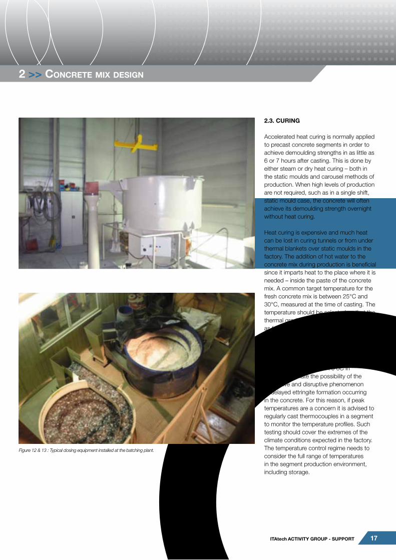
Figure 12 & 13 : Typical dosing equipment installed at the batching plant.

18 GuIdelIne FoR Good pRACTICe oF FIBRe ReInFoRCed pReCAST SeGMenT – VoluMe 2 : pRoduCTIon ASpeCTS
The use of accelerating admixtures can enable a slight reduction in the level of heat required for curing but this is usually not cost effective. Recent developments in admixtures containing C-S-H hydration initiators have proven to be viable in reducing heat curing of precast concrete segments. Where heat reduction through admixtures is required, the approach is to be selected by the mix designer in context with overall constraints.
Another way of reducing the amount of heat required for curing is to use a concrete maturity monitoring system in the curing tunnel of a carousel. By knowing the temperature profile and history within a segment and inputting this temperature and time data into the known maturity characteristics of the mix, the actual real-time compressive strength of the segment can be determined and the temperature within the curing tunnel can be adjusted down so as to impart only the minimum amount of energy required to achieve demoulding strength.
2.4. CooRdInATIon oF STRuCTuRAl deSIGn And MIX deSIGn
The method and sequence of construction, from pre-casting to installation, needs to be coordinated between the segment designer and the supply chain and the contractor installing the segments on site, as segments have to be designed for all design situations within their lifecycle, including temporary cases such as demoulding, stacking and erection of segments.
For temporary design situations stresses are generally calculated by elastic methods to ensure that the flexural strength of the unreinforced concrete is not exceeded and thus the segments remain uncracked. Otherwise, steel reinforcement should be included into segments to withstand the anticipated bending due to handling.
2.4.1. Handling and Transportation
It should be noted that divergences between the assumptions made in the structural design of the segments and design of clamps and supports, and implementation in the production process are a common cause for segment damage from handling and transportation. Therefore, handling and transportation need to be coordinated between the segment designer and the segment manufacturer. The checks need to follow the full life cycle of the segment from production to installation, and in particular the support conditions (extent of lifting pad, lifting points) in combination with the concrete strength associated with the particular design situation.
In each case, the applied load is the dead weight factored by a dynamic amplification factor representing actions arising from acceleration and deceleration of the segments. Typical factors range from between 1.5 to 3, based on the sensitivity of the design approach.
Extreme cases for segment end support and central support are presented below. Please note that handling and transportation checks should mirror the actual support conditions, such as a more distributed support for use of vacuum pads. The resulting maximum shear force and bending moment in both support cases are checked against the time dependent capacity of the fibre reinforced concrete.
2.4.2 Storage
The segments are generally stored in stockpiles separated by timber or plastic bearers as shown in the above sketch. A tolerance for the misalignment between two consecutive supporting wedges shall be
2 >> concrete mix desiGn
Figure 14 : Thermocouple based maturity monitoring system.
Case 2 : Central supports.
Case 1 : Lateral supports.
Segment stacking.

19ITAtech ACTIVITY GRoup - SuppoRT
considered: a value of 50mm is recommended as a minimum value, and should be agreed with the construction team.
The maximum reaction forces and bending moments for the bottom segment of a stockpile shall be considered in the segment design. Where the segments have insufficient capacity, the stacking height for “young” segments is typically reduced.
2.4.3. Compressive Strength
The characteristic 28 days compressive strength of the FRC will be specified by the designer of the segmental lining. This is generally in the range 40 to 60 MPa. Typically, the early strength requirement for demoulding (usually around 12 to 18 MPa) dictates that the concrete should have a water/cementitious (W/C) ratio of below 0.38. Durability requirements may well dictate that the W/C ratio is below 0.35. In these cases, the ultimate characteristic strength of the concrete will be > 70 MPa, depending upon the cementitious blend used and the concrete curing temperatures reached. The compressive strength of FRC in segmental linings can be in excess of 100 MPa after 90 days or longer.
The development of the mix design for FRC segmental linings needs to be conducted well in advance of segment production as there are many variables to be taken into account. For projects in remote areas or locations with little or no track record in high performance concretes, it is worthwhile for contractors to evaluate the local concrete and materials supply chain during the tender stage of the project.
2.4.4. Tensile and Flexural Tensile Strengths
Similar to the compressive strength, the tensile and flexural tensile strength will be specified by the designer of the segmental lining. The flexural tensile strength represents the
tensile resistance of a segment in bending, as opposed to resistance in direct tension. While both parameters have a strong correlation they should be specified and tested separately.
Tests of flexural tensile strength are typically beam tests, as specified by the designer, e.g. the beam test specified in EN 14651, or ASTM based tests. It should be noted that the type of test must be specified by the designer and cannot be changed without the designer’s confirmation.
Flexural tensile strength is typically tested at 3 and 28 days as a minimum. The early age tests are required to confirm the capacity of the segments for design situations associated with early ages, such as stacking and handling. Tests typically capture the flexural tensile strength at first cracking, and the post crack residual strength at various strain levels.
The post crack strength is delivered by the structural fibres incorporated into the concrete. The correlation between post crack strength, fibre type and fibre content is not well defined, and contains a number of unknowns. Post crack flexural strength values specified by the designer will therefore typically require substantiation by an appropriate testing programme to generate a sufficient statistical data base.
2.4.5. Tolerances
Precast concrete tunnel lining segments, as any precast concrete product, need to be manufactured to specified dimensional tolerances. The tolerances should be specified by the lining designer at a reference temperature in order to eliminate the effects of thermal expansion/ contraction when measurements are taking place and ensure that accurate comparisons can be made. Alternatively, the actual temperature during the measurements needs to be converted to the reference temperature.
Similarly, segment moulds will also require to have dimensional tolerances specified by the lining designer. Several international documents contain suggested tolerances for precast tunnel lining segments, such as • The British Tunnelling Society Specification
for Tunnelling, 3rd Edition 2010• DAUB (German Tunnelling Committee)
Recommendations for the design, production and installation of segmental rings (TTB 2014)
However, any tolerances should always be selected recognising the actual demands of the project. For further information on tolerances please refer to Annex A.In addition to specifying the dimensional tolerances for moulds and cast segments at a reference temperature, the designer should also specify the methods and techniques to be used for measurement. The most accurate method is a 3D laser tracker system.
2 >> concrete mix desiGn

20 GuIdelIne FoR Good pRACTICe oF FIBRe ReInFoRCed pReCAST SeGMenT – VoluMe 2 : pRoduCTIon ASpeCTS
3 >> Quality control For Precast seGments
3.1. InTRoduCTIon
The requirements for the segments are the basis for the planning and execution of quality control. The specified requirements resulting from design and design standards will define the methods and frequency of investigations, alongside with specific requirements from the client.
General requirements resulting from the project’s segmental lining design are :• Resistance to design stresses
(compression, tension, flexure)• Ductility• Durability
The quality control programme needs to establish reasonable confidence in the performance of the concrete mix and its constituents to deliver the required performance throughout the design life of the structure. Any quality control program should be developed in a manner so to link into the locally available design and testing standards (ACI, Eurocode) as well as the locally available tests.
Quality control is commonly differentiated into :• Initial testing• Continuous production control
Initial, pre production testing will be carried out to ensure the proposed mix and the proposed manufacturing process are capable of delivering a product complying with the project specific requirements. Quality control during production is required to demonstrate the segments achieve the expected performance during production.
Quality control should establish the acceptance criteria for segments, and
repair procedures for defective segments. These criteria should be agreed with the client before segment production starts.
3.2. InITIAl TeSTInG
The aim of initial testing of the fibre reinforced concrete is to confirm the overall concept of design and have an initial indication of the controlling test parameters. A key factor is to ensure a homogeneous mix can be achieved.
Depending on the duration of testing, initial tests often have to be conducted well in advance of full production. This is especially the case when durability requirements, such as water permeability, biogenic attack, sulphate attack or similar, are specified.
The initial testing should also include investigation of the mixes with the maximum allowed deviations of the proposed mix design. This will define the tolerances for the production process. For the production of fibre reinforced concrete segments, the batching weight tolerances are usually taken as those within the respective National Standard, such as EN 206.
In the phase of the initial testing load-tests of whole elements (full scale testing) or fire resistance testing (if required) may be conducted to verify the design. It is normally impractical to undertake any non-standardised testing for production control.
3.3. pRoduCTIon ConTRol
Production control is required to establish assurance of the quality of the finished product (the segment), as used on site. Its key role is to flag up irregularities in the
supply of constituent products, and in the manufacture of segments.
Segments are typically stockpiled and stored for a considerable time before being used on site, as a just in time production process for segments would typically be considered unacceptably risky. It is therefore possible to approve the use of segment batches based on tests undertaken in the course of production control, and to identify and quarantine batches where the required performance has not been reached.
The frequency of production control should therefore be selected considering the production process, and ensure that only a limited amount of the segment production is at risk of being compromised if a test fails.
3.4. QuAlITY ConTRol plAn
The quality control plan summarises production procedures and parameters where they have the potential of influencing the quality of the concrete, as well as initial and production control testing. The tests are specified in terms of type of testing, frequency of testing, and the associated acceptance criteria. In addition to the pass/fail criteria for the tests it would be expected to contain procedures implemented if the required values are not achieved. Further, the quality control plan shall capture how records of the testing will be kept and distributed.
It is recommended to base the quality control plan on appropriate standards, such as EN 206. The following section is based on EN 206, however it is expected that the principles can be adopted to other national standards or guidelines.

21ITAtech ACTIVITY GRoup - SuppoRT
3.4.1 Conformity testing
The various tests undertaken for the segment concrete are designated as conformity testing, which is generally grouped into control of the following aspects:1. Control of the constituent materials2. Control of equipment 3. Control of production procedures and of
concrete properties
Conformity testing is undertaken for the initial testing as well as for the continuous production testing.
3.4.2. Control of the constituent materials
Minimum requirements for the production control of the constituent materials are presented in EN 206 Table 22. The production control is undertaken with the following staged approach:• Inspection of delivery ticket prior to
discharge/use. This is mandatory for each delivery. It is recommended to take and store samples.
• Visual inspection of aggregate and test of density for additions in suspension. Likewise, this test is mandatory for each delivery.
• Testing of specific parameters, e.g. sieve analysis for aggregate. These tests are mandatory as initial test, and whenever a supplier is changed. Depending on the reliability of the local supplier it is recommended to undertake these tests periodically.
The quality control plan should contain procedures and tests if there is doubt about the properties of the constituent materials.
As the performance requirements for the concrete and the aggregate are often governed by local conditions in terms of exposure and availability it is highly recommended to develop a bespoke testing plan geared to the local situation.
3.4.3. Control of equipment
Similar to the constituent materials, the equipment used in the production of segments requires control during production. The requirements of EN 206 Table 23 represent a similar staged approach to inspection as the production control of the constituents outlined above :• Daily visual inspection of the plant. This
should be preferably carried out before the first use of the production day.
• The temperature in the casting area should be monitored and recorded, with a plan in place as to what to do if the temperature falls outside the range required by the mix design.
• Specific metered installations such as the water meter should be inspected on installation, and periodically afterwards. The inspection interval should be established with the supplier of the equipment, as it depends on the conditions of its use.
It is advisable to include references to the testing and maintenance schedule of the equipment in the quality control plan. Further it is recommended to include workflows for the testing of specific equipment (such as the admixtures dispensers, and for monitoring water content in aggregates, in particular sands), to be executed if there is doubt about the performance of specific elements of the plant.
3.4.4. Conformity of concrete
The testing requirements should be established on the basis of standards generally applicable to the works. Testing should generally be representative for the expected placement conditions, and the preparation and transport of the concrete mix employed in testing should represent the actual production conditions as far as practicable. It is recommended to undertake all concrete testing on the basis of testing triplets, i.e. one test constituting of the testing of three individual specimen, in order to facilitate interpretation of the results and to identify outliers. In addition to testing of the concrete itself, the constituents of the concrete such as aggregates, admixtures, cement and water, need to be quality tested. Appropriate tests are often available from the suppliers who undertake testing in the course of their respective quality management plan.Key pre production tests for fibre reinforced concrete are presented below. The suggested tests must be validated against project specifications and code requirements, and the previous experience of the supply chain with segment production. In particular, the possible exposure of concrete to aggressive environmental conditions needs to be assessed, and a specific testing regime be developed. These tests would be undertaken in addition to the tests suggested below.Please note that a pre production test typically consists of a minimum of 3 samples of not less than 2m3 of concrete. The total number of individual tests (e.g. compressive strength) is (number of samples) x (number of tests) x (number of specimen per test).
3 >> Quality control For Precast seGments

22 GuIdelIne FoR Good pRACTICe oF FIBRe ReInFoRCed pReCAST SeGMenT – VoluMe 2 : pRoduCTIon ASpeCTS
3.4.4 «Conformity of concrete»
Where there are specific design requirements, e.g. permeability, an increase in the number and/or frequency of the tests should be considered.
The production/compliance tests need to be developed on a project specific basis, and, as for the pre production testing, need to consider local standards as well as the experience of the supply chain with segment production.
3.4.5. Fibres
Properties of fibres have to be defined. For fibres the definitions could follow ASTM A820 or EN 14889-1 for steel fibres and EN 14889-2 for polymer fibres. Fibres need to be subject to quality assurance, for example by a CE marking, and used in line with the manufacturer’s instructions where they are generally subject to the quality control by the manufacturer.
It is important to note that the attainment of a CE mark under these standards does not automatically dictate that the fibre is suitable for use in precast segments. Specific project testing should always be undertaken to ensure that the fibre type and dose can achieve the required performance specification.
It is worth noting that the comparison of fibres in terms of the number of kilos used to achieve specific requirements, either in standards or reference projects, may not always be a reliable indicator of its performance in a specific application. As such specific project testing should always be undertaken.
3.4.6. Geometry of Segments
The geometry of segments must be confirmed on the cast segment, not on the mould. Mould tolerances need to be selected
by the mould manufacturer so that the finished product conforms to the specified dimensions and tolerances. Production control includes check and re-adjustment of the moulds on the basis of dimensions taken on the segments.
The quality control plan needs to define the conditions, such as temperature, under which the geometry tests take place.
3.4.7. Marking of Segments
The quality control system should include a way to mark the segments so they can be tracked through the project, at a minimum this should include the date the segment was removed from the mould and the mould number. This would enable matching between a batch of concrete and the segments it was used to produce, in the event testing shows a batch of concrete had failed to reach the required design values the affected segments could be identified and quarantined while a solution is worked out by the project team.
A best practice solution would mark each segment with a bar code, this would allow encoding significantly information and could be combined with the required construction markings (type of segment and location in the ring). If the segments will remain accessible during the permanent works, they could also be fitted with barcodes that will remain visible in the permanent state. This would allow the client to cross-reference the exact strength of the segments with the production records during inspections, asset management and planning for future works.
3.5. ASSeSSMenT oF ConCReTe pRopeRTIeS
This section provides additional information on the assessment of concrete properties.For concrete used in the manufacture of segments the same procedure adopted for ordinary concrete should be followed for assessment of the compressive strength. Tensile properties of the concrete are tested
3 >> Quality control For Precast seGments
pRe pRoduCTIon TeSTS peR SAMple RATIonAle
Compressive strength
(n) tests at (3) @ 3 days(3) @ 7 days(6) @ 28 days(3) @ 56/90 days
Performance for early age and regular design situations. Establish late age hardening effect for ductility validation
Modus of elasticity (1) @ 28 days Assurance for segment design
Tensile splitting strength
(3) @ 3 days(6) @ 28 days(3) @ 56/90 days
Performance for regular design situationsCorrelation between compressive and tensile strength
Flexural strength(3) @ 3 days(6) @ 28 days(3) @ 56/90 days
Performance for early age and regular design situations.
Density of hardened concrete
As per compressive strength To verify concrete production
Fibre content (1) fibre washout test on fresh mix To verify concrete production
Water permeability (1) @28 days To confirm compaction

23ITAtech ACTIVITY GRoup - SuppoRT
with beam tests to establish flexural strength (e.g. with 3 point tests on the EFNARC beam, EN 14651), and with tensile splitting tests (e.g. EN 12390-6).The following text is based on a classification of the material according to Model Code 2010, and testing undertaken to associated standards. The variables used in the assessment represent the characteristic residual flexural strength at the following test situations : fL,k At limit of proportionality/LOP (first crack) fR1,k At a crack mouth opening displacement
of 0.5mm (representative for SLS) fR3,k At a crack mouth opening displacement
of 2.5mm (representative for SLS)
The method to establish compliance can be adopted to other test and other suites of standards.
When undertaking concrete tests in the pre-production phase, the test results can be considered successful if :• The characteristic value of fR1,k is higher than
value specified in the design;• The ratio between fR3,k and fR1,k fulfils the
design specification; if a higher strength ratio is obtained the material can be accepted (if no specific prescriptions are present in the design)
• The ratio between flexural strength values prescribed in the Model Code 2010 for substituting the traditional reinforcement with fibre is verified (fR1,k / fL,k > 0.4 and fR3,k / fR1,k > 0.5).
In order to define the characteristic value from the tests results, the procedure suggested in Eurocode 0 can be used. With the average value mx, the coefficient of variation Vx is defined as :
and Vx =sx/ mx
The characteristic value is defined as :
The value of kn is defined according to ISO 12491, with the use of a Student’s distribution :
with t0.05 fractile of the t- distribution for the probability 0.05. The value of kn for different number of specimen is reported in Table 1.
This procedure is based on the assumption that the coefficient of variation Vx is unknown.In Model Code 2010 a relationship between average and characteristic value is given only for fR1.
and as a consequence :
The relationship proposed in Model Code is based on a coefficient of variation equal to 0.20. There is little data available in the literature for large production that can confirm this data. It has to be noted that the dispersion of the results depends from different factors (such as fibre content, fibre geometry, concrete rheology).
If data is available from large production of a similar concrete mix, the coefficient of variation can be considered known. In this case the coefficient kn is equal to :
with u0.05 fractile of the standardized normal distribution for the probability 0.05. Values of kn
for different number of specimen are reported in Table 2.
If some major changes in the mix that can modify the properties of the material are made, the procedure for the initial qualification of the fibre reinforced concrete should be repeated.
3.5.1. Initial tests
Assessment of concrete properties at early age
The segment design quite often specifies characteristic values of residual strengths at different ages (e.g. at demoulding or first handling). For validating these early age parameters, procedures adopting a lower number of tests can be defined. This approach assumes that the process of the concrete curing in the controlled conditions of segment manufacturing has a low inherent variability. It is recommended to verify this assumption by comparing the variability of early age test
3 >> Quality control For Precast seGments
n Kn
3 3.37
4 2.63
5 2.34
6 2.18
8 2.01
9 1.96
10 1.92
12 1.87
15 1.82
n Kn
3 1.89
4 1.83
5 1.80
6 1.77
8 1.74
9 1.73
10 1.72
12 1.71
15 1.70
Table 1 : Value of Kn for unknown Vx. Table 2 : Value of Kn for unknown Vx.

24 GuIdelIne FoR Good pRACTICe oF FIBRe ReInFoRCed pReCAST SeGMenT – VoluMe 2 : pRoduCTIon ASpeCTS
results to the results obtained on the 28 day specimen.
As an example, it is possible to perform a limited number of tests at different curing ages to define increase of the average value over the curing time, and therefore evaluate the characteristic value with a suitable number of tests only at 28 days. With the hypothesis of having the same increase in time for both the average and characteristic value of the residual strengths it is then possible to estimate the characteristic value at different ages.
Assessment of concrete properties at the long term
In order to verify possible changes in the peak post tensile behaviour over time it is also suggested to perform some tests on samples at 56 and 90 days. Concrete used in precast production can exhibit a significant increase of matrix strength after 28 days of curing (this is particularly witnessed when using supplemental cementitious materials such as GGBS or PFA). This can lead to increases in fibre bond and fibre failure can occur. This phenomenon is usually managed by using the correct fibre for the corresponding compressive strength of the matrix.
Further tests
Some tests can be made with the aim to determine the correct fibre content. The fibre content can be measured at fresh or hardened state according to EN 14721. Tests at hardened state can be made on segments by drilling cores and evaluating the fibre content in each core.
This allows verification that the fibre was homogenously distributed throughout the segment. Furthermore, by sawing each core into layers, it is possible to inspect the correct distribution of the fibre in the segment thickness (identifying possible fibre segregation). Usually a fibre content that is measured according to EN 14721 should have no more than a 20% variance compared to the nominal value.
3 >> Quality control For Precast seGments

25ITAtech ACTIVITY GRoup - SuppoRT
3.5.2.Tests during production
The procedure for the quality control during segment production should be specified on the basis of requirements produced by the designer. This shall take into account the forecast production rate (number of segments per day), and the potential variation of the production test results through time.
It is recommended to perform flexural tests on the fibre reinforced concrete in addition to compressive tests. For this purpose, beam test according to EN 14651 can be performed to control the residual strengths during the production. It is suggested to test a sample of at least 3 beams for every test.
The conformity control can be made adopting the same approach of EN 206 for concrete in compression. If more than 15 data points are considered, the mean values should respect the conditions :
As an example, a typical quality control tests for large production can prescribe 3 beam tests every casting day coming from a single batch. The average of the 3 beam tests results is defined. The conformity control can be made considering 15 consecutive days results (average of three beams). In this way, moving average and variation can be evaluated from an adequate number of tests.
The conformity control can be made by adopting the same approach of EN 206 if a sufficient number of tests is forecast (e.g. tests every day or two days of production). If the frequency of control is low, a control procedure similar to the initial test one can be proposed (definition of characteristic value according to Eurocode 0).
3.6. non ConFoRMInG SeGMenTS
The contractor and designers should define and agree a procedure for the use of the segments that fail quality control. Ideally this should be in place before the start of segment production.
Typical solutions would be using the segments in parts of the tunnel where imposed loads are lower than the worst design case (lower cover, different ground, etc), using the segments in ‘sacrificial’ areas (inside shafts / station boxes /similar) or using the segments as bulk fill / ballast (for instance placed inside large mass concrete pours in shaft base slabs, replacing an equivalent volume of poured mass concrete). Disposal or dumping of the segments should be considered the last resort.
The procedure should include a process for identifying why the concrete failed quality control and what measures have been put in place to prevent future failures.
3 >> Quality control For Precast seGments

26 GuIdelIne FoR Good pRACTICe oF FIBRe ReInFoRCed pReCAST SeGMenT – VoluMe 2 : pRoduCTIon ASpeCTS
>> annex 1
pReCISIon 3d MeASuReMenT oF MouldS And SeGMenTS
performance specification
Tapered rings enable the tunnel lining to accommodate alignments that contain curves or to compensate for misalignment of the tunnel due to site-specific problems. The use of Fibre Reinforced Segments necessitates more precise segments and greater care in their installation is needed.The reasoning for specifying the very tight tolerances in these standards are :1. Geometric sensitivity to inaccuracies and
distortions of individual segments2. High load effects from earth, water and
grouting pressure on the tunnel lining3. Jacking forces during mining4. The load transfer takes place only in limited
areas (partial surface load)5. Damage cannot always be detected (for
example, on the outer side of the ring)6. Repairing of damaged segments are costly
and time-consuming
Tolerances
Most projects include a requirement in the tender documents that specifies compliance with the tolerances indicated in one of the several international standards, most of which were issued prior to the use of fibre reinforcement or the availability of the current measurement technologies. Many of these international standards already call for sub millimetre accuracy on several key dimensions. Ring designers will frequently modify these values according to project specific requirements. All of these standards are however incomplete with respect to the requirements of current precision measurement techniques and fail to include full traceability of the segment, its constituent components, manufacturing process, dimensional accuracy and installed location as part of an ongoing Quality Assurance / Quality Control process.
On some projects there is only a passing reference to the tolerance and quality control requirements which enable the contractor or precast company to bypass the checking that is implied in the standards / guidelines. The simple addition of a few clarifying clauses in the tender documents are called for to significantly improve this. The inclusion of all of these requirements in a table or diagrammatically on a single composite diagram will dramatically improve the understanding of the requirements and assist in their implementation. (See figures 1-4)
The total quality control should be clearly defined as the responsibility of the contractor who should supervise the segments supplied by the precast company.
Key points to add include :1. The reference temperature that the
segments should achieve the specified tolerances.
2. The time after de-moulding when precision measurement of the segment is acceptable.
3. A clear measurement regime should be specified such as:
a. Dimensional Measurement control of all moulds at manufacturers’ factory including segment detail such as bolt hole size and position, gasket grooves etc.
b. Check Dimensional Measurement control of all moulds on the precast production line (either static or carousel before mass production), this should include a check on any torsion.
c. The measurement location (e.g. roofed hall with temperatures between 15 and 20°C) should be specified in the construction contract.
d. Three Dimensional Measurement control of all segments after first pouring
e. Then after a given number of castings, the exact frequency can be varied according to the designer’s project specific requirements such as:
1) Dimensional Measurement control of all segments after the 10th casting from each mould.
2) Dimensional Measurement control of all segments after the 20th casting from each mould.
3) Dimensional Measurement control of all segments after the 30th casting from each mould.
Or 4) After the start of production, the 50th
ring produced from every formwork mould should be re-measured. The next measurements should be performed after every 100 castings, unless otherwise provided for in the construction contract.
5) If manufacturing tolerances are exceeded in any measurement, all segments produced after the last measurement (with compliant tolerances) must be re-measured working backwards from the most recent. All segments within the tolerances should be accepted, all segments exceeding the tolerances must be considered separately.
4. Tolerances on “closed” (built) ring must NOT be the sum of all individual tolerances.5. Individual tolerances should be compensated with the mathematical sign.6. Every controlled segment must be proved by a record sheet (physical or digital). A full segment documentation system should enable full traceability of the segment production; this should include all the constituent components of the segment, the production methods and durations, personnel responsible, tolerance measurements right through to the precise place the segment is installed in the finished tunnel.

27ITAtech ACTIVITY GRoup - SuppoRT
>> annex 1
TABulATed & dIAGRAMMATIC RepReSenTATIon oF ToleRAnCe ReQuIReMenTS.
SeGMenT lInInG ToleRAnCeS oF FABRICATIon Code SeGMenT ToleRAnCeS
According to BTS Specification for Tunnelling 3rd edition §204.4.1
According to dAuB Specification July. 2013 §3.5.3
Ring Size (internal diameter) Ref # §3.5.3 ≤8.0m ≥11.0m
Cross Setting Angle in Radial Joint:Angle of Joint Plane. Contact zone
βR 1.1 ±0.3mm ±0.5mm
Cross Setting Angle in Circumferential Joint:- Angle of Joint Plane. Contact zone
βC 1.1 ±0.3mm ±0.5mm
Angle of Radial Joint Taper βL5, βRβL5, βR 1.2 ±0.5mm ±0.7mm
Width of segment: W ±1mm 2.1 ±0.5mm ±0.7mm
Segment Thickness (on backs) T ±1.5mm 2.2 ±3.0mm ±4.0mm
External Segment Arch Length type A1, A2, A3, A4, A5 An, B, C. AE ±1mm 2.3 ±0.6mm ±0.7mm
External Segment Arch Length type K AE ±1mm 2.3 ±0.6mm ±0.7mm
Internal Radius of segment RI 2.4 ±1.5mm ±2.5mm
Diagonal 2.5 ±1.0mm ±2.0mm
Torsion 2.6 ±5.0mm ±8.0mm
Width of Gasket sealing groove WG ±0.5mm 3.1 ±0.2mm ±0.2mm
Depth of Gasket sealing groove TG ±0.5mm 3.2 ±0.2mm ±0.2mm
Radius (Position of Bolt Hole axis, Joint face (Contact Axis) and Gasket groove axis
RO 3.3 ±1.0mm ±1.0mm
Evenness (Flatness)of radial (Longitudinal) Joint: (Contact Zone) ER ±0.3mm (0.1mm)2 4 ±0.5mm ±0.8mm
Evenness (Flatness)of Circumferential Joint: (Contact Zone) EC ±0.5mm1 3 4 ±0.5mm ±0.8mm
Tolerances for Master Ring / Rings 5
External Diameter of Ring (Master Ring) ED 5.1 ±10.0mm ±15.0mm
Internal Diameter of Ring (Master Ring) ID ±0.2% ID or 6mm Maximum 5.2 ±10.0mm ±15.0mm
Outer Circumference (measured at 3 heights) 5.3 ±30.0mm ±45.0mm
Erector cones 6.1 ±2.0mm ±2.0mm
Size of Bolt holes +1/ -0.2mm
Position of Bolt hole and plastic dowels 1mm 6.2 ±1.0mm ±1.0mm
Pitch angle Segment Type A1, A2, A3, ..An B, C. αp ±0.02° ±0.02°
Pitch angle Segment Type K αp ±0.02° ±0.02°
Smoothness of faces other than joints ±1.5mm(smooth float) ±1mm (formed face)
Mismatch of Sealing Groove at corners ≤0.5mm
Lip between Adjacent segments on internal diameter (Master Ring) ≤3.0mm
Gap between longitudinal segment Joints (Master Ring) LI 1.0mm feeler gauge not passing
1 2.0mm feeler gauge not passing beneath a 1 m long straight edge
2 From the theoretical plane, with a rate of deviation not exceeding 0.6mm/m
(0.3mm Generally, 0.1mm in Radial Plane)
3 From theoretical plane, with rate of deviation not exceeding 1mm/m
Notes :1. It is not allowed that the Maximum tolerances add to one another, hence tolerances of the whole ring are smaller than the sum of the single tolerances.2. Two test rings shall be erected on a flat and level base with the top ring rotated one bolt pitch from the bottom ring with the bolts inserted. The base ring shall be retained as
the master-ring. Checks shall be made against the master-ring at intervals not exceeding 0.5% of the segment production.3. All given tolerances refer to a reference temperature of 20°C.4. In the case of inconsistencies of two dependent tolerances then the more stringent shall be relevant.5. Tolerances for Gasket groove (TG, WG) shall be in accordance with the requirements of the gasket supplier.

28 GuIdelIne FoR Good pRACTICe oF FIBRe ReInFoRCed pReCAST SeGMenT – VoluMe 2 : pRoduCTIon ASpeCTS
>> annex 1
Annex 1 Figure 1 : Legend of Designations - General
Annex 1 Figure 2 : Legend of Designations - Angle
Annex 1 Figure 3 : Legend of Designations - Joints

29ITAtech ACTIVITY GRoup - SuppoRT
>> annex 1
Annex 1 Figure 4

30 GuIdelIne FoR Good pRACTICe oF FIBRe ReInFoRCed pReCAST SeGMenT – VoluMe 2 : pRoduCTIon ASpeCTS
>> annex 1
Due to the often complex design of tapered rings there are frequently designs that have no parallel surfaces from which to measure the dimensional accuracy of either the moulds used to produce the segments or the segments themselves. To correctly check the individual dimensional accuracies would require a very time consuming measurement procedure using hand-held tools with highly skilled personnel or the use of a “dynamic full surface 3D measurement system”.
Annex 1 Figure 5
Annex 1 Figure 6

31ITAtech ACTIVITY GRoup - SuppoRT
>> annex 1
Such a system typically comprises a LaserTracker to carry out a measurement of all the contact surfaces, the radii, both the outer and the inner diameters as well as any detail such as gasket grooves and bolt-hole positions etc,. These measurements are analysed and processed via a traceable 3D metrology software platform and comparison is then made between the measured object and the nominal design. Any report that is made from the measurement of the tolerances should be as succinct as possible but as comprehensive as necessary to impart the necessary information. (see example below Figures 5-8)
Annex 1 Figure 7
Annex 1 Figure 8

32 GuIdelIne FoR Good pRACTICe oF FIBRe ReInFoRCed pReCAST SeGMenT – VoluMe 2 : pRoduCTIon ASpeCTS
>> annex 2
Ce MARkInG
The basic information given in the CE marking is the following :• Type of fibres: steel/polymer; • CE Certification;• Type and dimension;• Tensile strength;• Young’s modulus;• Length;• Cross sectional form;• Diameter or dimensions of cross section;• Surface finish and anchorage (eg. hooked at
the end or embossed);• Tolerances on the length, the diameter (and
the aspect ratio for steel fibres);• Safety aspects.
In addition the declaration of performance under standard tests is reported.For CE-marking of fibres, two levels of attestation of conformity are defined: System 1 and System 3.System 1 is applicable when the fibres have a structural function, i.e. when the fibres are designed to contribute to the load-bearing capacity. The system requires a continuous surveillance of the production process of the fibres by an independent Certifying Body, which delivers a certificate of conformity (CE- mark).
System 3 is applicable when fibres are used for other reasons, i.e. for some non-structural function - for instance to reduce the risk of plastic shrinkage, or to improve the behaviour of concrete in fire. This system allows the manufacturer alone to declare that the quality is in accordance with the requirements of the standard: no confirmation by a third party is necessary.
In practice, therefore, when the post-crack strength of fibre concrete is taken into account in the structural design, the fibres must be certified under System 1, and the CE label on the packaging must indicate that the fibres are certified for structural use (System 1).
SYSTeM 1 SYSTeM 3
Field of use
Structural use A) Non structural use
Quality control
• Initial type Testing (ITT) under the responsibility of the Notified certification Body
• Initial and Annually Factory Production Control (FPC) assessment by Notified Body
• Certification institute → “Certificate of Conformity”
• Initial Type Testing by a Notified Laboratory
• Factory Production Control (FPC) under responsibility of the manufacturer
• The manufacturer creates and signs a “Declaration of conformity”
A) Structural use of fibres is where the addition of fibres is designed to contribute to the load bearing capacity of a concrete element
Difference between attestation under System 1 and System 3.

33ITAtech ACTIVITY GRoup - SuppoRT
>> annex 2

34 GuIdelIne FoR Good pRACTICe oF FIBRe ReInFoRCed pReCAST SeGMenT – VoluMe 2 : pRoduCTIon ASpeCTS

35ITAtech ACTIVITY GRoup - SuppoRT

long
rine
04 9
0 14
48
48 -
(217
86 -
06/1
8)
ITA Secretariat - c/o MIe2 – Chemin de Balexert 9 - CH-1219 Châtelaine (GE) - SwitzerlandTel. : + 41 21 693 23 10 - Fax : + 41 21 693 41 53 - Email : [email protected] - Web : www.ita-aites.org