itasa v.10 cr i
TRANSCRIPT

‘A... c_ ItASA i I CR 82Q v.10
‘L . .
I.
-. ‘- :
. . ;
WASHINGTON, D. C. l JULY 1967
-

- TECH LIBRARY KAFB, NM
I1111111111111111111111IIllII 0079883 NAYACR-8XY
ANALYSIS AND DESIGN OF SPACE VEHICLE
FLIGHT CONTROL SYSTEMS
VOLUME X - MAN IN THE LOOP
By Richard M. Smith
Distribution of this report is provided in the interest of information exchange. Responsibility for the contents resides in the author or organization that prepared it.
Issued by Originator as GDC-DDE66-023
Prepared under Contract No. NAS 8-11494 by GENERAL DYNAMICS CONVAIR
A DIVISION OF GENERAL DYNAMICS CORPORATION San Diego, Calif.
for George C. Marshall Space Flight Center
NATIONAL AERONAUTiCS AND SPACE ADMINISTRATION
For sole by the Clearinghouse for Federal Scientific and Technical Information
Springfield, Virginia 22151 - CFSTI price $3.00


FOREWORD
This report was prepared under NASA Contract NAS 8-11494 and is one of a series intended to illustrate methods used for the design and analysis of space vehicle flight control systems. Below is a complete list of the reports in the series:
Volume I Volume II Volume III Volume IV Volume V Volume VI Volume VII Volume VIII Volume M Volume X Volume XI Volume XII Volume XIII Volume XIV Volume XV Volume XVI
Short Period Dynamics Trajectory Equations Linear Systems Nonlinear Systems Sensitivity Theory Stochastic Effects Attitude Control During Launch Rendezvous and Docking Optimization Methods Man in the Loop Component Dynamics Attitude Control in Space Adaptive Control Load Relief Elastic Body Equations Abort
The work was conducted under the direction of Clyde D. Baker, Billy G. Davis and Fred W. Swift, Aero-Astro Dynamics Laboratory, George C . Marshall Space Flight Center. The General Dynamics Convair program was conducted under the direction of Arthur L. Greensite.
iii


TABLE OF CONTENTS
SectiOn Page
1. STATEMENT OF THE PROBLEM . . . . . . . . . . . . 1
2. STATEOFTHEART . . . . . . . . . . . . . . . . 3
3.
4.
2.1 Transfer Function Approach ........... 3 2.2 . Simulation and Test .............. 10
RECOMMENDED PROCEDURES. ............ 15
REFERENCES. .................. 23
V

LIST OF ILLUSTRATIONS
Figure Page
1 SystemswithManinthe Loop . . . . . . . . . . . . . 4
2 Control Loop with a Quasilinear Operator-Describing Function . . 5
3 Vibration Tolerance of the Human Operator . . . . . . . . 16
4 Typical Missile Pitch Channel Control Loop . . . . . . . . 17
5 Gain and Filter Coefficients for Control Loop Stability . . . . . 18
6 Placement of Man in the Loop . . . . . . . . . . . . . 19
vi

1. STATEMENT OF THE PROBLEM
Man’s role in the operation of vehicle control systems has developed both from precedent and from scientific considerations. In early aircraft man carried out the guidance function and stabilized the system; the closed-loop response of the system was unstable without man in the loop. In modern aircraft, stability is maintained by the autopilot, but man remains in the control loop, even though it is sometimes necessary to adjust the stability augmentation of the system in order to allow him to participate. Over the years, man’s primary role in aircraft control systems has evolved from that of a stabilizing element to that of a systems manager.
Missile control, on the other hand, has evolved wothout man in the loop, partly because of the catastrophic nature of failures and partly because this concept was within the state of the art. While aircraft systems have been augmented and automated to better utilize man’s managerial capability, missile systems are being de-automated to allow man to participate. Historically, then, man has had a role in control system operation, although the nature of this role has not always been obvious. One of- the basic and most difficult questions that must be answered for all manned control system designs is: “How much should man participate ?I’ Unfortunately, the answer has not always been the product of scientific analysis. The design problem is tc develop the control configuration which results in the most effective combination of man and machine,


2. STATE OF THE ART
Two general scientific approaches for considering man as part of a control loop are being pursued by researchers and engineers. Each has some merit and provides some information; neither has proved itself superior to the point of eliminating the other. The approaches differ in their basic premise and in their technical disciplines. The general approaches to be considered are:
a. Development of transfer functions to express control relationships.
b. Simulation of system dynamics and environment and evaluation of operator performance.
2.1 TRANSFER FUNCTION APPROACH
The transfer function (or describing function) approach is a natural one for the controls engineer. The development of human operator transfer functions has progressed along two divergent paths. One approach has been to provide a model of human control activity in a structural or microfunctional sense. This work attempts to duplicate the neuromuscular interconnections and logic that result in human control motion. Current efforts in this endeavor are concerned with understanding and ex- pressing the elementary mechanics of human sensors, receptors, and actuators. This work has not yet progressed to where the results are directly usable in conven- tional vehicle control system analyses.
The second approach, the quasilinear transfer function approach, is more general and is applicable in vehicle control system analyses. The quasilinear transfer function is a mathematical model which expresses an analogous cause-and-effect con- trol relationship. The approach evolved from the observation that many nonlinear sys- tems have, for some inputs, responses similar to those of linear systems. Non- linear system responses for this sort of system may be divided into two parts: the response of similar linear system; and the difference between the linear response and the actual nonlinear response. The second component is called the “remnant. It Thus the linear model plus the remnant produces an exact cause-and-effect relationship. For different applications the remnant must change in order for the nonlinear system to be represented accurately.
Human operator response depends on the conditioning or training of the oper- ator and the information presented to him. To show this dependence, control systems with man in the loop have been classified as compensatory, pursuit, or precognitive(8). Man may operate in any of these modes and may change from one to another. Block diagrams of the systems are shown in Figure 1.
3

In a compensatory system, the operator observes the difference between a com- manded state and an existing state and exercises control by reducing this difference, or error. This mode of operation is most like a conventional feedback servo system, and it lends itself to simple linear representation and analysis. However, it is difficult in a real system to limit the information presented to the human to nothing but the error. The human operator, is continuously receiving information from his senses of touch, balance, hearing, and vision, and he will respond to one, all, or any combination of the inputs he selects.
In a pursuit system, the operator is presented with the system input, the system output, and the error. This sort of system more nearly approximates a practical
r ____--_------- HUMAN OPERATOR 1
I I
LIMB- I APPLIED LIMB
SENSORY FORCE OPERATOR
EQlJALIZATlON bOUTPUT MANIPULATOR PoSIT1oN CONTROLLED -
FORCE DYNAMICS DYNAM1CS
I Tt' I _
g ELEMENT I I I L I ---_----------a
a. Compensatory System
r - - - - TiUMAN OPERATOR ---------1 I
I I
LIMB- I APPLIED
OPERATOR1 LIMB
EQUALIZATlON - FORCE
,OUTPUT lMANl”ULATOR POSITION CONTROLLED
+ FORCE DYNAMICS IDYNAMICS b ELEMENT
I
Tt4 I I I ______ ----- ----- _: b. Pursuit System
r - - - - DUGAN OPERATOR ---
1 I I
I v 1
I SENSORY LIMB
OPERATOR~MANIPULATOR POSITION CONTROLLED OUTPUT IDYNAMICS l ELEMENT
b DYNAMICS,
I
i-------------l
c. Preco.qlitive system
Figure 1. Systems with Man in the Ioop
4
situation than does a compensatory system and is more difficult to analyze. If the input (commanded condition) is periodic, or if he thinks it is, the operator will anticipate the error and apply a correction before the error exists. This sort of response can result in a negative delay time. This of course, cannot be accomplished with an automatic system. In a pursuit tracking situation the human operator selects the things to which he will respond, and may or may not choose to anticipate a control motion requirement.
In a precognitive system, the operator acts as though he has been preprogram- med. Some stimulus starts his response, and from there he continues in a completely defined and predictive way until he has accomplished the task. Pilots are often trained to respond to emergency situations in a precognitive way. For example, if a pilot notices that his airspeed is below a critical value, he will increase power and dive the aircraft, even though he may be at low altitude. This precognitive response occurs because the pilot has been preconditioned to recognize that the insufficient airspeed is intolerable and immediate action must be taken for survival. He will act to correct the low altitude after he has achieved sufficient airspeed to continue flying.
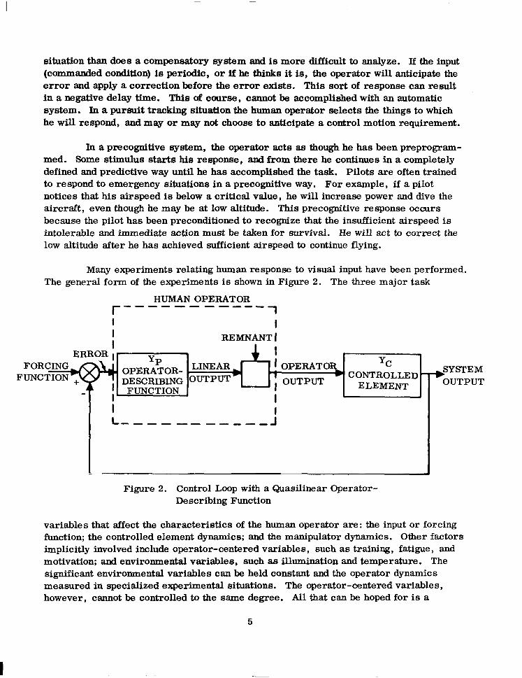
Many experiments relating human response to visual input have been performed. The general form of the experiments is shown in Figure 2. The three major task
HUMAN OPERATOR f
-B--B- ----w 1
f I
a REMNANT 1
ERROR ; YP
OPERATOR- L1NEAR) YC SYSTEM
DESCRIBING oUTpUT CONTROLLED + ELEMENT OUTPUT
FUNCTION I
I L m--------e- :
Figure 2. Control Loop with a Quasilinear Operator- Describing Function
variables that affect the characteristics of the human operator are: the input or forcing function; the controlled element dynamics; and the manipulator dynamics. Other factors implicitly involved include operator-centered variables, such as training, fatigue, and motivation; and environmental variables, such as illumination and temperature. The significant environmental variables can be held constant and the operator dynamics measured in specialized experimental situations. The operator-centered variables, however, cannot be controlled to the same degree. All that can be hoped for is a
5

reasonable level of stationarity- -that is, an experimental situation in which the statistics do not change with time. Stationarity is assumed to be satisfied if the subjects being tested are limited to a small, select, highly trained, and highly motivated group.
For compensatory tracking situations, the human is adequately represented by a quasilinear model consisting of a describing function and a noise remnant. (I) Dynamics of the display and other system elements are lumped into a “controlled element. ” The control loop is described by time functions and their Fourier transforms and as power spectra or power spectral densities. The controlled element is defined by its linear constant-coeefficient transfer function. The human operator is represented by a linear-describing function and nonlinear, time-varying remnant. This is neces- sary to provide an adequate description in the sense that the system response of the actual and quasilinear system are the same.
Test results indicate that the forcing function and controlled element dynamics are the most influential of the three task variables. The manipulator dynamics appears to have less influence in the frequency ranges appropriate for human control. Results of a large number of experiments provide data for empirical assembly of a describing function for human operator performance in a compensatory tracking situation with a visually presented random appearing forcing function. This describing function is the linear portion of the human pilot model; the remnant portion remains to be considered.
The linear portion of the human pilot model consists of two element&):
a. A generalized describing function, and
b. A series of adjustment rules to determine the parameters in the generalized describing function so that it becomes an approximate model of human behavior for the particular situation of interest.
The most extensive and generalized describing function form for one and two dimensional compensatory control tasks is:
y : K ,-Wr
P P
(TL jw + 1) aT K-
T =m
(TIP + 1) 2 2Bnjw I + 1
W n 1 (Tn jw + 1)
1
where
KP=gafn T = reaction time delay (transport lag)
6

TLjw+l
TI jw + 1 = equalization characteristic
K aT TOT
0
= indifference threshold describing function
1
26n jw = neuromuscular system charac-
+ 1 W
1 (Tn jw + 1)
teristic.
n 1
The describing function is written in terms of frequency, W, instead of Laplace transform variable, s, to emphasize that this describing function is valid only in the frequency domain and exists only under essentially stationary conditions. For example, it cannot be used to compute the system response to a discrete input such as a step function.
The indifference threshold effect was empirically determined in tests performed by the Goodyear Corporation. ( 2g) The ratio of threshold to input aT is small relative to
( > OT to the value, 1, for input signals commonly used in tracking tests, and when combined with KT the result is near unity. The indifference threshold is of secondary importance in common compensatory tracking tasks, and is therefore often ignored (8).
The third order neuromuscular system description given in the model was based on high frequency data available from tests using step function inputs. Tests designed to evaluate humans in compensatory tracking tasks have not adequately evalu- ated the third order neuromuscular system because of insufficient forcing-function power at frequencies as high as Wn. The tests did, however, measure the low-frequency effects of the neuromuscular system, and the results support approximation of the neuromuscular system by a first-order lag. The usual approximation for neuromuscular lag term is to use(l)
(Tn jw + l.)-l
where
Tn=T + (2 6y.J
5 W n
Thus, the general form of the low-frequency describing function for the human
7

operator becomes:
K c-jwT yzp
(TL P + 1)
P (Tn jw + l)(TI jw + I)
This equation has been shown experimentally to be applicable for wide range of forcing functions, manipulators, and controlled elements. It must be applied with caution, however, because the coefficients will vary as necessary to reflect the pilot efforts to stabilize the system and to minimize the RMS error@).
The pure time-delay term, c-jwT, results from human sensor excitation, nerve conduction, computational lags and other data-processing activity in the central nervous system. Experimental results show T tc be essentially constant when consid- ered as a function of controlled element dynamics and forcing function. It does vary, however, when considered as a function of the subject being tested. The value of T will normally be between 0.1 and 0.2 set(“).
The neuromuscular lag, Tn, varies with the task. The adjustment required is obscure because details of the variations have not been adequately measured, and the muscular control mechanisms involved are not well understood. The observed variation of Tn with forcing function is between 0.1 and 0.6 second. The variation is often ignored, and the value commonly used to represent a human operator is 0.1 second.
The equalization characteristic and the gain, Kp (TL jw +l)/(TI jw +l), are the major elements in the human transfer function which allow the human to stabilize differing dynamic devices. These elements modify their input into a suitably scaled and phased neuromuscular command to cause the closed loop system response to be stable and the error to be minimum. The coefficients of the equalization terms require alteration for each different type of input in order to adequately represent the human operator. The adjustment of the equalization describing function includes both adapt- ation and optimalization. The adaption process selects a form and coefficients which are compatible with good, low-frequency, closed-loop response and absolute stability of the system. The optimalizing process selects coefficients which, in general, min- imize the RMS error. The value of TL (lead) will normally vary between 0 and 2.5 seconds. TI (lag) will normally vary between 0 and 20 seconds, and KI, (gain) will usually be between 1 and loo(“).
The adjusting rules for the human operator describing function are summarized as follows:(l)
a. Stability - The human adapts his equalizing characteristics to achieve stable control.
8

b. Form Selection, Low Frequency -The human adapts the form of his equalizing characteristic to achieve good, low-frequency, closed-loop system response to the forcing fun&Jon. A low-frequency lag, TI, is generated when the following two conditions apply.
1. The lag would improve the system low-frequency characteristics.
2. The controlled element characteristics are such that the introduction of the low-frequency lag will not result in destabilizing effects at higher frequencies which cannot be overcome by a single first order lead, TL, of indefinite but modest size.
c. Form Selection Lead - After good, low-frequency characteristics are assured, lead is generated if the controlled element characteristic together with the reaction time delay are such that a lead term would be essential to retain or improve high- frequency system stability.
d. Coefficient Adjustment - After adaptation of the equalizing form, the describing function coefficients are adjusted so that:
1. Closed-loop, low-frequency performance in operating on the forcing function is optimum in a somewhat analogous sense to that required to minimize the mean-square tracking error.
2. The system phase margin, pm, is directly proportional to the forcing function frequency, Wi, for values of Wi less than about 2 rad/sec. The strong effect of forcing function on phase margin is associated with the variation of T, (neuromuscular lag) with frequency.
3. Equalization time constants TL or TI, when ~/TL or l/T1 << O,, will be adjusted such that low frequency response is insensitive to slight changes in TL or TI (Wi << UC).
e. Invariance Properties
1. oc, Kc Independence: After the initial adjustment, changes in controlled element gain, Kc, are offset by changes in pilot gain, over frequency, UC, is invariant with Kc.
Kp; that is, the cross-
2. tic, Oi Independence: System crossover frequency depends only slightly on forcing function frequency for Wi < 0.8 wco. (WC0 is the value of WC used for q-WC.)
3. WC Regression: When Oi approaches the value of 0.8 WC 0
or becomes greater
than 0.8 oco, the crossover frequency decreases to values much lower than oco.
9

The human operator establishes the lead, lag, and gain terms (compensates) without conscious effort. However, he does not compensate the closed-loop response in zero time. Studies are in progress with the aim of establishing an expression for the transient period that exists while the human operator is developing his compensation(2). The time may be as long as 15 to 30 seconds which can be catastrophic in an emergency situation requiring immediate corrective action. When the human operator loses con- trol of the system he will move the controls to extremes or in an effort to establish a known pattern to which he can respond in an precognitive manner. If this results in establishing a recognized pattern or in stabilizing the closed-loop response, all is well. If not, disaster.
2.2 SIMULATION AND TEST
The third method to be considered for evaluating man in a control loop involves using a human test subject in a simulated system. The method most commonly used is to simulate the dynamics of the system on an analog, digital, or hybrid computer, con- struct an appropriate physical model of the environment, and then test selected human subjects. The control system adequacy is evaluated by the qualitative judgement of trained and experienced test subjects.
This is a direct approach to the design of a control system for use by human operators. The technique has the advantage of providing a direct system evaluation, even to the point of becoming a training device for system operators. However, the technique may result in the development of systems that are similar to each other. Design and construction of cockpits and environment are expensive, require long lead time, and combine scientific and artistic talents. There is a tendency to reuse part of or complete systems designed and built for some other application. This can be justified economically, but it may narrow the approach.
The criteria for determining man’s exact role in any vehicle control system are not clear(lg). Many tests and experiments have been performed to evaluate man’s capability, and quasilinear describing functions for some detailed tasks have been developed. These, however, do not provide insight for determining what man’s role should be. Without question, the human operator can “sometimes” provide control capability that is not available in hardware or software. The “sometimes” involves human char- acteristics that defy numerical evaluation. They involve psychological considerations as well as the fact that man can choose his own course of action and his choice may or may not be based on scientific considerations. The determination of man’s role is often based on the fact that his presence is required for some other purpose. For example, a pilot may be required to execute a complex control function such as load relief, selecting a target, or landing the vehicle. When man is present he is, by convention, given command authority over the system. Command requires that the pilot be provided adequate information to exercise his judgement and adequate means to interrupt or alter any automatic control function. To be capable of performing in a control loop he has interrupted, the pilot must be actively monitoring the loop. Since
10

he is required to perform as though he were an essential part of the loop, he may as well be made an essential part of the loop. In this manner the pilot may acquire con- trol functions which could have been done efficiently with atuomatic systems.
A control system changes drastically when man is placed in the loop. A con- ventional, stable control loop is designed so that the input command is compared to the system output to produce an error signal. The error signal is used to drive some con- trolled element in a manner which will reduce the error. Note that the system is based entirely on the existing state of the system elements. A man does not operate the same as hardware in the control loop. Man compares the desired state of the vehicle with the state that will exist if things remain as they are. He then plans one or a series of actions that he thinks will ultimately result in the desired state. Note that man extrapolates the solution in time. The existing state of the system may or may not be of primary sign& ficance. The extrapolation in time makes man a unique control system element. Man can replace some system elements, however, the inverse is not generally true.
In order for man to operate in a control loop he must be provided with data concerning the present state of the vehicle, the desired state of the vehicle, and, if possible, the likely state if no actions are taken. Man normally receives information for control purposes through the tactual senses, balance, hearing, and vision. The tactual senses respond to pressure and temperature of objects on the skin. This sense is strongly involved with skill in manipulation of control devices. The sense of balance is based on highly developed sensors in the middle ear. The sensor in the middle ear detects the direction of the total acceleration vector and, together with the tactual sense allows for coordinated motions against physical restraint. If the physical restraint is not there, such as in free-fall, the sense of balance (acceleration detection) is disrupted. Hearing and vision both involve distance reception in that bcdily contact is not required for sensor stimulation. Hearing sensors respond to mechanical vibrations in a frequency range that is defined as sound. The human ear is sensitive to changes in sound intensity, changes in frequency, and, in a gross sense, changes in direction. The ear is capable of receiving information that is finely structured in time; that is, information is received and processed sequentially over a finite time. The eye receives spatial or total image information, and is not as adept at receiving information finely structured in time. Hearing is primarily employed for communication, and for signals requiring immediate attention such as emergency alarms.
Vision is the primary channel for control system input to the human operator. The electromagnetic energy spectrum to which the eye is sensitive is transmitted in straight lines. Unlike the reflected mechanical vibrations of sound, the eye preserves a formal one-to-one spatial correspondence of object to image. The retina of the eye is the surface upon which the visual image is formed. It is a mosaic of more than 100 million individual receptor cells, each capable of producing an individual response. The acuity of vision is large only at the center of the field. Complex patterns are not perceived all at once by the person. one’s attention and eyes move from detail to detail, and the mental or internal model preserves the spatial correspondence. Each eye
11

fixation adds to the -internal model. The total model developed for control consists of many individual eye fixations combined with the internal model generated from other sensors as well as the processes of thought and memory. This sort of saccadic eye action has led to the investigation of sample data representations for visual trackingt2’).
The success of the simulation and test technique for “man in the loop” control development is strongly dependent on the quality or fidelity of the simulator model. The state of the art for simulator construction has developed to provide essentially all phys- ical cues to the human operator over limited dynamic ranges. Simulators have been developed that provide a complete cockpit environment in size, arrangement, lighting, temperature, appropriate out-the-window view, motion with six degrees of freedom, sound, appropriate instrument indications, control manipulations, etc., identical to those required in the true situation. Two conditions have not been simulated. The first is zero “g” for the obvious reason that it can be achieved only in free fall. The second is the psychological effect of the fact that the operator knows that he is in no real danger while operating the simulator. Thus his basic drive for survival is gen- erally not involved. The significance of this fact is not clear. Experience indicates that satisfactory results are achieved when selected, trained and motivated test subjects are used.
The technique for rating the control system performance and adequacy by test subjects has been standardized to a certain degree. One rating system commonly used is the Cooper Rating system. This system has been used extensively in evaluation of piloted systems. A single instance of rating would not convey much information. How- ever, multiple ratings using carefully controlled experiments provide much information. The evaluation can be improved if historical data of similar experiments are available from which general conclusions can be drawn. The rating system is one in which the test subject numerically rates the system between 1 and 10. A rating of one is best; a rating of 10 indicates catastrophic failure. The numerical ratings are described in Table 1. In general, a system rating must fall in the “satisfactory” category (numerical rating 1, 2, or 3) for normal operation. The rating must not go below “unsatisfactory” (numerical rating 4, 5, or 6) after failure of any stability augmentation required to achieve a “satisfactory” rating.
I.2
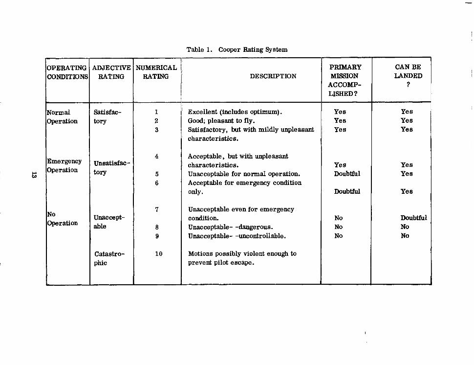
Table 1. Cooper Rating System
OPERATING CONDITIONS
Normal Operation
Emergency Operation
No Operation
ADJECTIVE RATING
Satisfac- tory
Unsatisfac- tory
unaccept- able
Catastro- phic
NUMERICAL RATING
1 2 3
4
5 6
7
8 9
10
DESCRIPTION
Excellent (includes optimum). Good; pleasant to fly. Satisfactory, but with mildly unpleasant characteristics.
Acceptable, but with unpleasant characteristics. Unacceptable for normal operation. Acceptable for emergency condition only.
Unacceptable even for emergency condition. Unacceptable- -dangerous. Unacceptable- -uncontrollable.
Motions possibly violent enough to prevent pilot escape.
PRIMARY MISSION
ACCOMP- LISHED?
Yes Yes Yes
Yes Yes Doubtful Yes
Doubtful Yes
No Doubtful No No No No
CAN BE LANDED
?
Yes Yes Yes


3. RECOMMENDED PROCEDURES
The design approach recommended for placing man in the control loop of boosters is to use a combination of two of the techniques discussed. The initial investigation can be effectively and economically accomplished using the quasilinear transfer function approach. The more advanced and detailed studies can be better accomplished by phys- ical simulation of the environment, computer simulation of the dynamics, and system evaluation by trained test subjects.
The first essential task of the control system analyst is to achieve a thorough understanding of the system to be controlled. The equations describing the motion of the vehicle, including elastic response and fuel sloshing (for liquid-fueled boosters) are essential for the analysis. The transfer functions of control system elements such as the control actuators, angular rate and position sensors, programmers, autopilots and stability augmentation devices are also required. The design criteria for the vehicle under consideration will include specification and analysis of the allowable loads that may be imposed on the structure throughout the boost phase. For the unmanned vehicle, a computer model or computer simulated booster system has been made to “fly” various flight profiles through various wind conditions. The overall stability of the control system has been determined throughout the flight, and the various loads evaluated. The equations and studies’ performed to describe these conditions are essential because when man is placed in the control loop, it will be necessary to modify the existing control system by gain changes, filtering, or by incorporating additional components to make the system compatible with human capabilities. Also, when man is on board his physical limitations and safety as well as the vehicle’s structural limit- ations must be considered in the design criteria. Figure 3 shows, in a general way, the limitations of the human operator as a function of frequency.
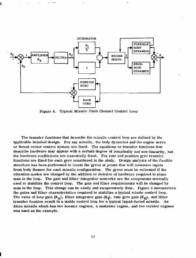
The complete equations of motion that describe the missile have been derived and are included in Volume I of this monograph series. These equations should be mech- anized on a computer to economically and effectively perform control systems stability analyses. Volume II of this monograph series describes the linear and nonlinear analysis methods applied to missile control design. In general, the basic stability analyses for the unmanned vehicle will have been accomplished before “man in the loop” can be accomplished with a planar simulation; i. e. , simulation of angular motion about a single axis such as the pitch or yaw axis. The single degree of rotational freedom representation is compatible with the assumptions and limitations of the quasilinear transfer function of the human operator. The transfer function of the human operator does not include cross-coupling terms and does not apply to control about more than two axes. Thus, it is not necessary for the preliminary vehicle simulation to contain these terms. It is necessary, however, to consider each degree of rotational freedom in the preliminary analysis, but, they must be considered uncoupled and done separately. Figure 4 shows a typical single degree of rotational freedom control loop.
15

10 I I I I I I I I Illll
I I I/
TOLERANCE
ONE-MINUTE TOLERANCE
’ ’ ’ ’ ’ ’ TOLERANCE ’ ’ ’ ’ ’
/
1. 10.
FREQUENCY (cps)
Figure 3. Vibration Tolerance of the Human Operator
16
INTEGRATOR
XI FLEXIBLE
4 s
% L
--, FILTER -
4 1 DYNAMICS
I POSITION GYRO
RATE + GYRO
Figure 4. Typical Missile Pitch Channel Control Loop
The transfer functions that describe the missile control loop are defined by the applicable detailed design. For any missile, the body dynamics and the engine servo or thrust vector control system are fixed. The equations or transfer functions that describe hardware may appear with a certain degree of complexity and non-linearity, but the hardware coefficients are essentially fixed. The rate and position gyro transfer functions are fixed for each gyro considered in the study. Design analysis of the flexible structure has been performed to locate the gyros at points that will minimize inputs from body flexure for each missile configuration. The gyros must be relocated if the vibration modes are changed by the addition or deletion of hardware required to place man in the loop. The gain and filter-integrator networks are the components normally used to stabilize the control loop. The gain and filter requirements will be changed by man in the loop. This change can be easily and inexpensively done. Figure 5 summarizes the gains and filter characteristics required to stabilize a typical missle control loop. The value of loop gain (KA), filter integrator gain (Kf), rate gyro gain (KK), and filter transfer function result in a stable control loop for a typical liquid-fueled missile. An Atlas missile which has two booster engines, a sustainer engine, and two vernier engines was used as the example.
17

After the control loop has been defined and the stability of the overall missile con- trol system analyzed, man can be inserted in the control loop. The analyst is confronted with the problem of determining where to place man in the loop. There are two pos- sibilitie s . The first, and most obvious possibility is to place man so that he interrupts the forward loop and thus has complete manual control. (See Figure 6a.) The ability . of a pilot to maintain stability about all three axes in such a system is marginal at best. The task is particularly difficult because the pilot is required to change his gain and his lead or lag compensation coefficients at various stages of flight. Also, the changes in compensation for the roll channel are not the same as those required in the pitch or yaw channels. This mode of operation may suffice as an emergency procedure to pre- vent disaster, but it does not represent an ideal solution to the control problem.
END-TO-END BOOSTER SUSTAINER
SYSTEM GAINS PITCH g. YAW PITCH & YAW
Position
KA 1.5 1.25
(de@%) Rate
KA KR (deg-set /deg) WR)
Integral
KA KI (deg/deg-set) WI)
VERNIER VERNIER PITCH YAW
--IT -‘- --
T = 0.033 o<t<24 T = 0.0116 24 ct
1
(0.04s l 1)
Figure 5. Gain and Filter Coefficients for Control Loop Stability
18

RATE ti GYRO
POSITION GYRO
a. Pilot Interrupts Forward LOOP
.
I RATE + GYRO
l
!PoSITION
GYRO -
b. Optional Pilot Participation
Figure 6. Placement of Man in the Loop
19

The second possibility is to design a system that is stable and can operate autono- mously, but that can be interrupted, monitored, augmented, or commanded as desired by the pilot. (See Figure Sb.) Pilot participation is dependent on operational require- ments instead of engineering necessity. The pilot is the only available control system element that can be used in this way. For example, reliability enhancement is an ap- propriate role for a pilot. In this role he would assume control of any portion of the system that failed. This function would require the pilot to evaluate the total situation, and to determine whether or not a failure existed. If a failure occurred, he would be required to determine what had failed and to assume control of that portion of the system. One disadvantage of this concept is that in order to interpret the situation the pilot would require extensive displays to depict the system operational status. The control system design could include some adaptive features that automatically place the system under pilot control for some types of system-sensed failures. This would reduce the display problem. However, the pilot would be required to actively monitor or partici- pate in the control system throughout the flight because the human operator is unable to instantly adapt his response to stabilize a control loop. The transition from automatic control to pilot control csn be achieved if the pilot is performing the control actions in parallel with the automatic system.
Another appropriate pilot role is to act in specialized situations which are difficult or impractical to accomplish with automatic systems. One such situation would be load relief during boost. During the period when a booster experiences maximum aero- dynamic pressure the automatic control system may increase the loads imposed on the structure by giving steering commands in response to air buffeting. This occurs at a predictable time during the flight. A pilot could either take control or bias the control signals during this period to decrease flight loads. Other specialized situations for the pilot may include the issue of discrete commands for staging, delayed ignition of upper stages for guidance corrections, or attitude control of an upper stage vehicle. The pilots exact role may be logically determined by the mission details and by cost effec- tiveness trade-off studies between automatic and pilot controlled systems.
The final step in system design analysis consists of applying simulation and test techniques. The linear analysis has satisfied the basic stability criteria of the control loop, and has determined the desired roll of the pilot in the control loop. This sim- ulation and test procedure will replace the quasilinear transfer function, which was the computer representation of the pilot, with a trained test subject in a simulated environ- ment. Simulation of the equations of motion is an extension of the equations used in the linear analysis to include six degrees of freedom plus elastic response if appropriate. The output, however, will drive a series of display devices and motion simulators in the simulated environment instead of a pilot describing function. The development of appropriate display devices and motion simulators is a complex combination of art and engineering. The engineering problems are compounded by the presence of the human operator because his response ie dependent on the inputs or cues received from the simulator. Any cue which he receives that is not appropriate to the simulated condition may be detrimental to the desired result. Any false motion, sound, light, smell,
20

temperature, air motion, humidity or other cue may alter the response of the human operator. The design and fabrication of the environment simulator must not only pro- vide all appropriate cues, but it should also exclude all inappropriate ones.
The overall stability and adequacy of the control system is determined by pilot evaluation of the simulator performance. Selected and trained test pilots are required to perform each phase of control many times. They qualitatively evaluate the control system using a system such as the Cooper Rating Scale (Table 1). The instrumentation is changed and the stability of the vehicle is augmented until the system is rated as being adequate (Cooper Rating of 1, 2, or 3) by the test pilots.
At this point the simulation and test sequence results in a detailed specification of the cockpit instrumentation and a firm definition of the pilots role. The next step is the fabrication and test of flight hardware.
21


4. REFERENCES
1. McRuer, D. T. Graham, D. Krendel, E. S. and Reisener , W.
2. Young, L. R. and Stark, L.
3. Kelley , C. R.
4. Block, H. D. Kesler, C. Knight, B. W. and Rosenblatt, F.
5.
6. North, J. D.
7. Hardy, G. H. West, J. V. and Gunderson, R. W.
8.
9. Sadoff, M.
10. Webb, P.
Human Pilot Dynamics in Compensatory Systems, Air Force Flight Dynamics Laboratory, WPAFB, Ohio, Technical Report Number AFFDL-TR-65-15, July 1965.
Biological Control Systems - A Critical Review and Evaluation, NASA CR-190, March 1965.
Manual Control Theorv and ADplications. Office of Naval Research, 24 June 1964.
Cognitive Systems Research Program, Cornell ~~ ~-~ University, Report No. 1, 1961.
“Testing of Manned Flight Systems Conference”, AIAA, AFFTC, NASA FTC, December 4-6, 1963.
“Manual Control As A Stochastic Journal, Taylor and Francis Ltd 1963.
Process”, Erogonomics London, Vol. 6,
Evaluation of Pilots Ability to Stabilize a Flexible Launch Vehicle During First-Stage Boost, NASA TN D-2807, May 1965.
“Modern Man-Machine Systems Theory”, Class Notes from Lectures by McRuer, Graham, Stear, Fuller,.-Warren, Moore, Muckier, Senders, Belsley, Matheny, Jex. UCLA Summer Short Course, Sept. 1965.
A Study of a Pilots Ability to Control During Sim- ulated Stability Augmentation System Failures, Ames Research Center, Moffet Field, California, NASA TN D-1552.
Editor Bioastronautics Data Book, NASA SP-3006, 1964.
23
11. Krendel, E. S. and Barnes, G. H.
Human Frequency Response Studies, WADC Technical Report 54-370, June 1954.
12. Senders, J. W. Survey of Human Dynamics Data and a Sample Application, WADC Technical Report 59-712, Nov. 1959.
McRuer, D. T. and Krendel, E. S.
Dvnamic ResDonse of Human Operators. WADC Technical Report 56-524, Oct. 195’7.
13.
14. Garren, J. F. A Visual Flight Investigation of Hovering and Low- Kelly, J. R. and Speed VTOL Control Reauirements. NASA TN Reeder, J. P. O-2788, April 1965.
A Studv of Lonaitudinal Control Problems at Low and Negative Damping and Stability With Emphasis on Effects of Motion Cues, NASA TN D-348, Jan. 1961.
15. Sadoff, M. McFadden, N. M. and Heinle, D. R.
16. Teper, G. L. and Jex, H. R.
“Synthesis of a Manned Booster Control System Using Mathematical Pilot Models, ” IEEE 6th Annual Symposium, May 6-8 1965.
17. Obermayer, R. W. Swatrz, W. F. and Muckier, F. A.
Perceptual and Motor Skills - Interaction of Informations Displays With Control System Dynamics and Course Frequency in Continuous Tracki% Southern University Press, 1962.
Muckier, F. A. and Obermayer, R. W.
18. Compensatory Tracking and Oscillatory Control System Transients Perceptual and Motor Skills, Southern University Press, 1961.
19. Muckier, F, A. Current and Future Trends in Manual Control System Research, Bunker-Ram0 Corp., for NASA January 1965.
20. Li, Y. T. “Adaptive Functions of Man in Vehicle Control Young, L. R. and System, ” International Federations of Automatic Miery, J. L. Control (Teddington) Symposium, Sept. 1965.
21.
22.
McRuer, D. T. Unified Analysis of Linear Feedback Systems, ASD Technical Report 61-118, STI, July 1961.
Sadoff, M. Effects of Hieh Sustained Acceleration on Pilots Performance and Dynamic Response, NASA TN D-2067, July 1964.
24

23. Dolkas, 6; B. and Stewart, J. D.
24. Wingrove, R. C. Stinnett, G. W. and Innis, R. C.
25. Wingrove, R. C.
26. Wingrove, R. C.
27. Bekey, G. A.
28. Westheimer, G. and Conover, D.
29. Goodyear Aircraft Corporation
NASA-Langley, 1961 - 31 CR-829
Effect of Combined Linear and Oscillatory Accel- eration on Pilot Attitude Control Capabilities, NASA TN D-2710, March 1965.
A Study of the Pilot’s Ability to Control an Apollo Type Vehicle During Atmosphere Entry, NASA TN D-2467, August 1964.
“Trajectory Control Problems in the Planetary Entry of Manned Vehicle, ” Proc. of AIAA, Williams- burg, Va., Oct. 1965.
“Guidance and Control in Supercircular Atmosphere Entry, _ ” Presented to International Federation of Automatic Control Symposium in the Peaceful Uses of Space, Stavanger, Norway, June 21-24 1965.
“Man-Machine Systems and Biomedical Engineering, ” Notes from Industrial Course on Use of Hybrid Computers, 1965.
“Smooth Eye Movements in the Absence of a Moving Visual Stimulus, ” Journal of Experimental Psychology, Vol. 47, No. 4, April 1954.
Human Dynamics Study, Goodyear Aircraft Report GER 4750, 8 April 1952.
25