issue 2 2021 the arup journal
TRANSCRIPT

The Arup Journal Issue 2 2021
2 32/2021 | The Arup Journal
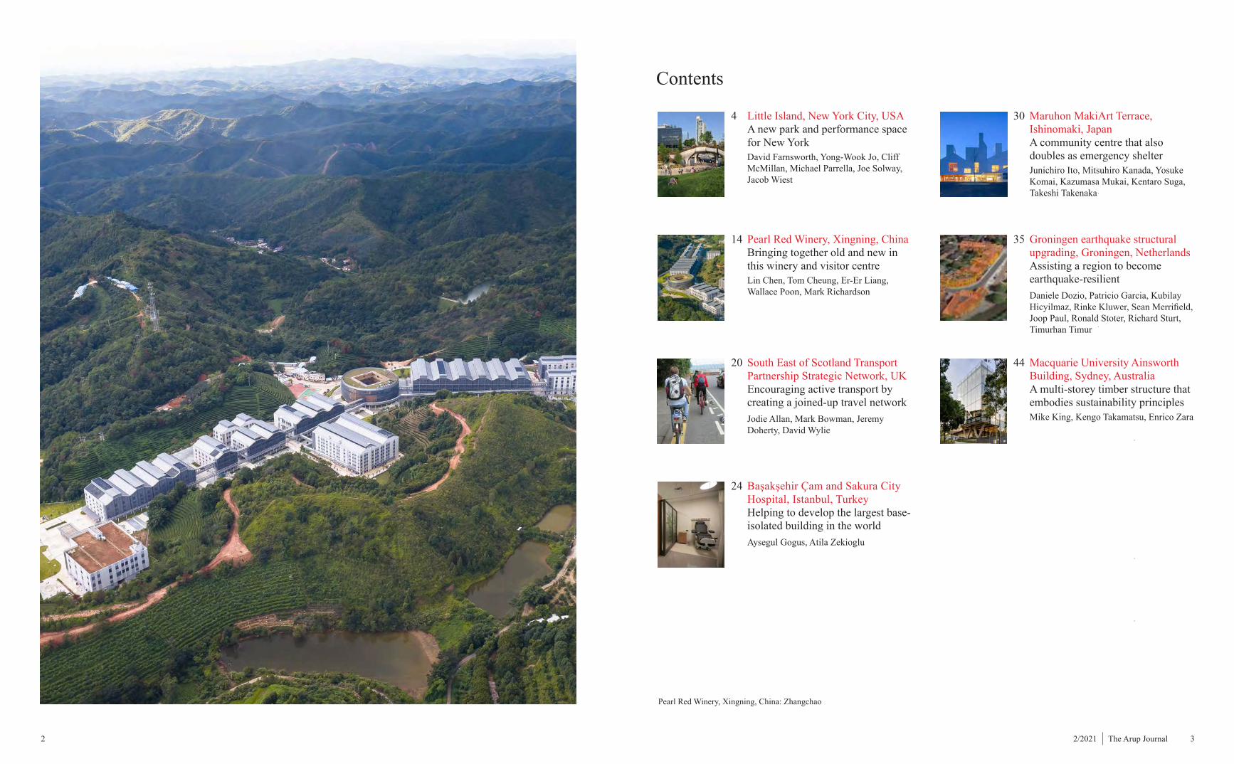
Contents
Pearl Red Winery, Xingning, China: Zhangchao
4 Little Island, New York City, USA A new park and performance space for New York
David Farnsworth, Yong-Wook Jo, Cliff McMillan, Michael Parrella, Joe Solway, Jacob Wiest
14 Pearl Red Winery, Xingning, China Bringing together old and new in this winery and visitor centre
Lin Chen, Tom Cheung, Er-Er Liang, Wallace Poon, Mark Richardson
20 South East of Scotland Transport Partnership Strategic Network, UK Encouraging active transport by creating a joined-up travel network
Jodie Allan, Mark Bowman, Jeremy Doherty, David Wylie
24 Başakşehir Çam and Sakura City Hospital, Istanbul, Turkey Helping to develop the largest base-isolated building in the world
Aysegul Gogus, Atila Zekioglu
30 Maruhon MakiArt Terrace, Ishinomaki, Japan A community centre that also doubles as emergency shelter
Junichiro Ito, Mitsuhiro Kanada, Yosuke Komai, Kazumasa Mukai, Kentaro Suga, Takeshi Takenaka
35 Groningen earthquake structural upgrading, Groningen, Netherlands Assisting a region to become earthquake-resilient
Daniele Dozio, Patricio Garcia, Kubilay Hicyilmaz, Rinke Kluwer, Sean Merrifield, Joop Paul, Ronald Stoter, Richard Sturt, Timurhan Timur
44 Macquarie University Ainsworth Building, Sydney, Australia A multi-storey timber structure that embodies sustainability principles
Mike King, Kengo Takamatsu, Enrico Zara
Little Island New York City, USA
4 52/2021 | The Arup Journal
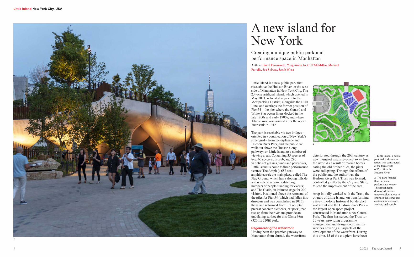
1: Little Island, a public park and performance space, was constructed at the former site of Pier 54 in the Hudson River
2: The park features three separate performance venues. The design team developed various usage configurations to optimise the slopes and contours for audience viewing and comfort
1.
Creating a unique public park and performance space in ManhattanAuthors David Farnsworth, Yong-Wook Jo, Cliff McMillan, Michael Parrella, Joe Solway, Jacob Wiest
A new island for New York
Little Island is a new public park that rises above the Hudson River on the west side of Manhattan in New York City. The 2.4-acre artificial island, which opened in May 2021, is located adjacent to the Meatpacking District, alongside the High Line, and overlaps the former position of Pier 54 – the pier where the Cunard and White Star ocean liners docked in the late 1800s and early 1900s, and where Titanic survivors arrived after the ocean liner sank in 1912.
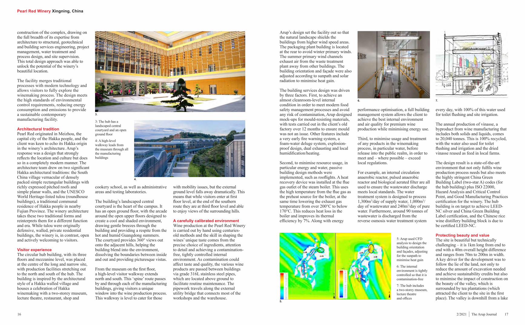
The park is reachable via two bridges – oriented in a continuation of New York’s street grid – from the esplanade and Hudson River Park, and the public can walk out above the Hudson along pathways on Little Island to a number of viewing areas. Containing 35 species of tree, 65 species of shrub, and 290 varieties of grasses, vines and perennials, Little Island is home to three performance venues: The Amph (a 687-seat amphitheatre); the main plaza, called The Play Ground, which has a sloping hillside and is able to accommodate large numbers of people standing for events; and The Glade, an intimate stage for 200 visitors. Positioned above the remnants of the piles for Pier 54 (which had fallen into disrepair and was demolished in 2015), the island is formed from 132 sculpted precast concrete elements, or ‘pots’, that rise up from the river and provide an undulating surface for this 98m x 98m (320ft x 320ft) park.
Regenerating the waterfrontHaving been the premier gateway to Manhattan from abroad, the waterfront
deteriorated through the 20th century as new transport means evolved away from the river. As a result of marine borers eating the old timber piles, the piers were collapsing. Through the efforts of the public and the authorities, the Hudson River Park Trust was formed, controlled jointly by the City and State, to lead the improvement of the area.
Arup initially worked with the Trust, the owners of Little Island, on transforming a five-mile-long historical but derelict waterfront into the Hudson River Park – the largest open space project constructed in Manhattan since Central Park. The firm has served the Trust for 20 years, providing programme management and design coordination services covering all aspects of the development of the waterfront. During this time, 15 of the old piers have been
2.
Little Island New York City, USA
6 72/2021 | The Arup Journal
rebuilt or upgraded and the continuous esplanade and park have been developed. Arup’s role has included assisting the Trust in working with the designers of the various elements to help define requirements and review their designs.
The firm began working on the Little Island project in 2013. Under the overall design management of prime consultant MNLA, and in collaboration with designer Heatherwick Studio and executive architect Standard Architects, Arup provided civil, structural, mechanical, electrical and public health engineering; audio-visual and theatre consulting; daylight planning; IT and communications consulting; and fire/life safety consulting.
Arup harnessed advanced 3D design techniques and digital solutions to achieve the project’s ambitious vision while also optimising constructability and enhancing the performance spaces. The close collaboration between the design and construction teams from
a very early stage, using the latest digital technologies including parametric and automated design, 3D modelling and digital fabrication processes, helped create this unique public space in New York.
Digital designLittle Island was conceived as a leaf floating on water, and so has a complex curved, undulating form, quite different from a typical pier. This presented significant challenges for the design, fabrication and erection of the structure. By pushing the precast technology past current convention, the architectural vision could be met using a unique structural system that was effective, constructible and, at the same time, visually intriguing. The design team moved away from conventional 2D drawings, which were not practical for the complex design, and fully embraced a 3D approach. Developing a design and construction model that fed directly into the digital fabrication process allowed the complex geometry elements to be realised.
Rhino or other BIM software, allowing for full coordination in 3D and clash detection using a Navisworks model created by importing each team member’s 3D components.
In the construction phase, Arup and the fabrication team at The Fort Miller Group utilised the models and scripts generated during the design process for direct digital input of the structural geometry into the fabrication of the pots. The design models fed into the robotic milling machines used to create the complex foam formwork. Arup’s models fully detailed the intricate 3D reinforcement within the pots and connection plates and embeds, enabling digital fabrication of the steel components required for the assembly and erection of the various pieces in Manhattan.
Hudson River environmentConstruction in the Hudson River area creates particular challenges because of the harsh marine environment, which contains chlorides and salt water, and the difficulty of casting in-situ concrete over a river. To overcome these issues, a precast concrete system was adopted. This durable system followed the typical construction methodology of precast piles driven into the riverbed. Supported on the piles, the complex exposed concrete precast pots that form the structure have a high architectural finish. An in-situ concrete slab was then poured on top to connect the pots together structurally and support the large volume of soil for the landscaping.
Arup specified a number of durability measures in the performance criteria for the concrete design, in order to account for the harsh environment. Corrosion inhibitor admixtures were included in the concrete mix, and grade 314L stainless steel connections and epoxy-coated reinforcement were used, as was a generous 75mm (3in) cover to the reinforcement.
PilesBedrock elevation varies significantly across the pier location, ranging from 21m (70ft) below water level near the
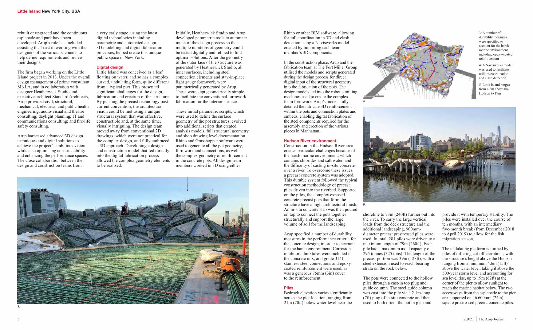
3: A number of durability measures were specified to account for the harsh marine environment, including epoxy-coated reinforcement
4: A Navisworks model was used to facilitate utilities coordination and clash detection
5. Little Island ranges from 4.6m above the Hudson to 19m
provide it with temporary stability. The piles were installed over the course of ten months, with an intermediary five-month break (from December 2018 to April 2019) to allow for the fish migration season.
The undulating platform is formed by piles of differing cut-off elevations, with the structure’s height above the Hudson ranging from a minimum 4.6m (15ft) above the water level, taking it above the 500-year storm level and accounting for sea level rise, up to 19m (62ft) at the corner of the pier to allow sunlight to reach the marine habitat below. The two accessways from the esplanade to the pier are supported on 46 600mm (24in) square prestressed precast concrete piles.
shoreline to 73m (240ft) further out into the river. To carry the large vertical loads from the deck structure and the additional landscaping, 900mm-diameter precast prestressed piles were used. In total, 281 piles were driven to a maximum length of 79m (260ft). Each pile had a maximum axial capacity of 295 tonnes (325 tons). The length of the precast portion was 39m (128ft), with a steel extension used to reach bearing strata on the rock below.
The pots were connected to the hollow piles through a cast-in top plug and guide column. The steel guide column was cast into the pile via a 2.1m-long (7ft) plug of in-situ concrete and then used to both orient the pot in plan and
Initially, Heatherwick Studio and Arup developed parametric tools to automate much of the design process so that multiple iterations of geometry could be tested digitally and refined to find optimal solutions. After the geometry of the outer face of the structure was generated by Heatherwick Studio, all inner surfaces, including steel connection elements and stay-in-place light gauge formwork, were parametrically generated by Arup. These were kept geometrically simple to facilitate the conventional formwork fabrication for the interior surfaces.
These initial parametric scripts, which were used to define the surface geometry of the pot structures, evolved into additional scripts that created analysis models, full structural geometry and shop drawing level documentation. Rhino and Grasshopper software were used to generate all the pot geometry, formwork and connections, as well as the complex geometry of reinforcement in the concrete pots. All design team members worked in 3D using either
3.
4.
5.
Little Island New York City, USA
8 92/2021 | The Arup Journal
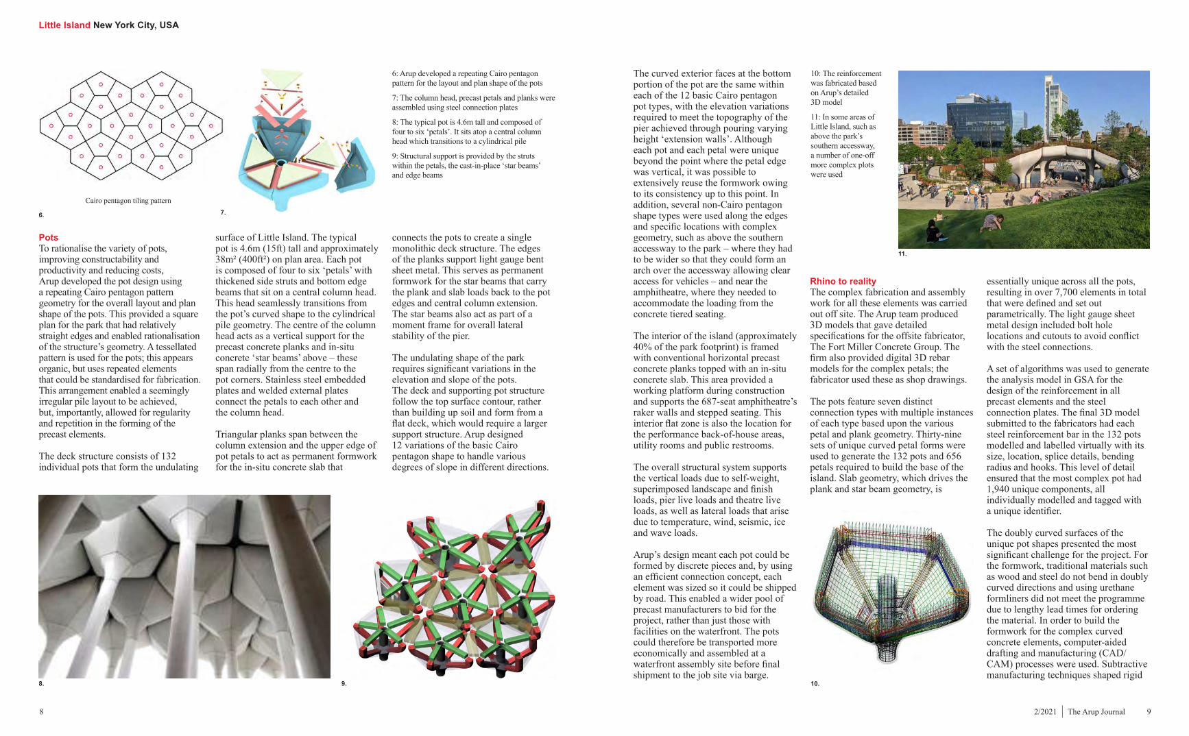
PotsTo rationalise the variety of pots, improving constructability and productivity and reducing costs, Arup developed the pot design using a repeating Cairo pentagon pattern geometry for the overall layout and plan shape of the pots. This provided a square plan for the park that had relatively straight edges and enabled rationalisation of the structure’s geometry. A tessellated pattern is used for the pots; this appears organic, but uses repeated elements that could be standardised for fabrication. This arrangement enabled a seemingly irregular pile layout to be achieved, but, importantly, allowed for regularity and repetition in the forming of the precast elements.
The deck structure consists of 132 individual pots that form the undulating
surface of Little Island. The typical pot is 4.6m (15ft) tall and approximately 38m² (400ft²) on plan area. Each pot is composed of four to six ‘petals’ with thickened side struts and bottom edge beams that sit on a central column head. This head seamlessly transitions from the pot’s curved shape to the cylindrical pile geometry. The centre of the column head acts as a vertical support for the precast concrete planks and in-situ concrete ‘star beams’ above – these span radially from the centre to the pot corners. Stainless steel embedded plates and welded external plates connect the petals to each other and the column head.
Triangular planks span between the column extension and the upper edge of pot petals to act as permanent formwork for the in-situ concrete slab that
The curved exterior faces at the bottom portion of the pot are the same within each of the 12 basic Cairo pentagon pot types, with the elevation variations required to meet the topography of the pier achieved through pouring varying height ‘extension walls’. Although each pot and each petal were unique beyond the point where the petal edge was vertical, it was possible to extensively reuse the formwork owing to its consistency up to this point. In addition, several non-Cairo pentagon shape types were used along the edges and specific locations with complex geometry, such as above the southern accessway to the park – where they had to be wider so that they could form an arch over the accessway allowing clear access for vehicles – and near the amphitheatre, where they needed to accommodate the loading from the concrete tiered seating.
The interior of the island (approximately 40% of the park footprint) is framed with conventional horizontal precast concrete planks topped with an in-situ concrete slab. This area provided a working platform during construction and supports the 687-seat amphitheatre’s raker walls and stepped seating. This interior flat zone is also the location for the performance back-of-house areas, utility rooms and public restrooms.
The overall structural system supports the vertical loads due to self-weight, superimposed landscape and finish loads, pier live loads and theatre live loads, as well as lateral loads that arise due to temperature, wind, seismic, ice and wave loads.
Arup’s design meant each pot could be formed by discrete pieces and, by using an efficient connection concept, each element was sized so it could be shipped by road. This enabled a wider pool of precast manufacturers to bid for the project, rather than just those with facilities on the waterfront. The pots could therefore be transported more economically and assembled at a waterfront assembly site before final shipment to the job site via barge.
essentially unique across all the pots, resulting in over 7,700 elements in total that were defined and set out parametrically. The light gauge sheet metal design included bolt hole locations and cutouts to avoid conflict with the steel connections.
A set of algorithms was used to generate the analysis model in GSA for the design of the reinforcement in all precast elements and the steel connection plates. The final 3D model submitted to the fabricators had each steel reinforcement bar in the 132 pots modelled and labelled virtually with its size, location, splice details, bending radius and hooks. This level of detail ensured that the most complex pot had 1,940 unique components, all individually modelled and tagged with a unique identifier.
The doubly curved surfaces of the unique pot shapes presented the most significant challenge for the project. For the formwork, traditional materials such as wood and steel do not bend in doubly curved directions and using urethane formliners did not meet the programme due to lengthy lead times for ordering the material. In order to build the formwork for the complex curved concrete elements, computer-aided drafting and manufacturing (CAD/CAM) processes were used. Subtractive manufacturing techniques shaped rigid
connects the pots to create a single monolithic deck structure. The edges of the planks support light gauge bent sheet metal. This serves as permanent formwork for the star beams that carry the plank and slab loads back to the pot edges and central column extension. The star beams also act as part of a moment frame for overall lateral stability of the pier.
The undulating shape of the park requires significant variations in the elevation and slope of the pots. The deck and supporting pot structure follow the top surface contour, rather than building up soil and form from a flat deck, which would require a larger support structure. Arup designed 12 variations of the basic Cairo pentagon shape to handle various degrees of slope in different directions.
6: Arup developed a repeating Cairo pentagon pattern for the layout and plan shape of the pots
7: The column head, precast petals and planks were assembled using steel connection plates
8: The typical pot is 4.6m tall and composed of four to six ‘petals’. It sits atop a central column head which transitions to a cylindrical pile
9: Structural support is provided by the struts within the petals, the cast-in-place ‘star beams’ and edge beams
10: The reinforcement was fabricated based on Arup’s detailed 3D model
11: In some areas of Little Island, such as above the park’s southern accessway, a number of one-off more complex plots were used
Rhino to reality The complex fabrication and assembly work for all these elements was carried out off site. The Arup team produced 3D models that gave detailed specifications for the offsite fabricator, The Fort Miller Concrete Group. The firm also provided digital 3D rebar models for the complex petals; the fabricator used these as shop drawings.
The pots feature seven distinct connection types with multiple instances of each type based upon the various petal and plank geometry. Thirty-nine sets of unique curved petal forms were used to generate the 132 pots and 656 petals required to build the base of the island. Slab geometry, which drives the plank and star beam geometry, is
8. 9.
11.
10.
6.
Cairo pentagon tiling pattern Typical Layout of Actual ‘Pot’7.
Little Island New York City, USA
10 112/2021 | The Arup Journal
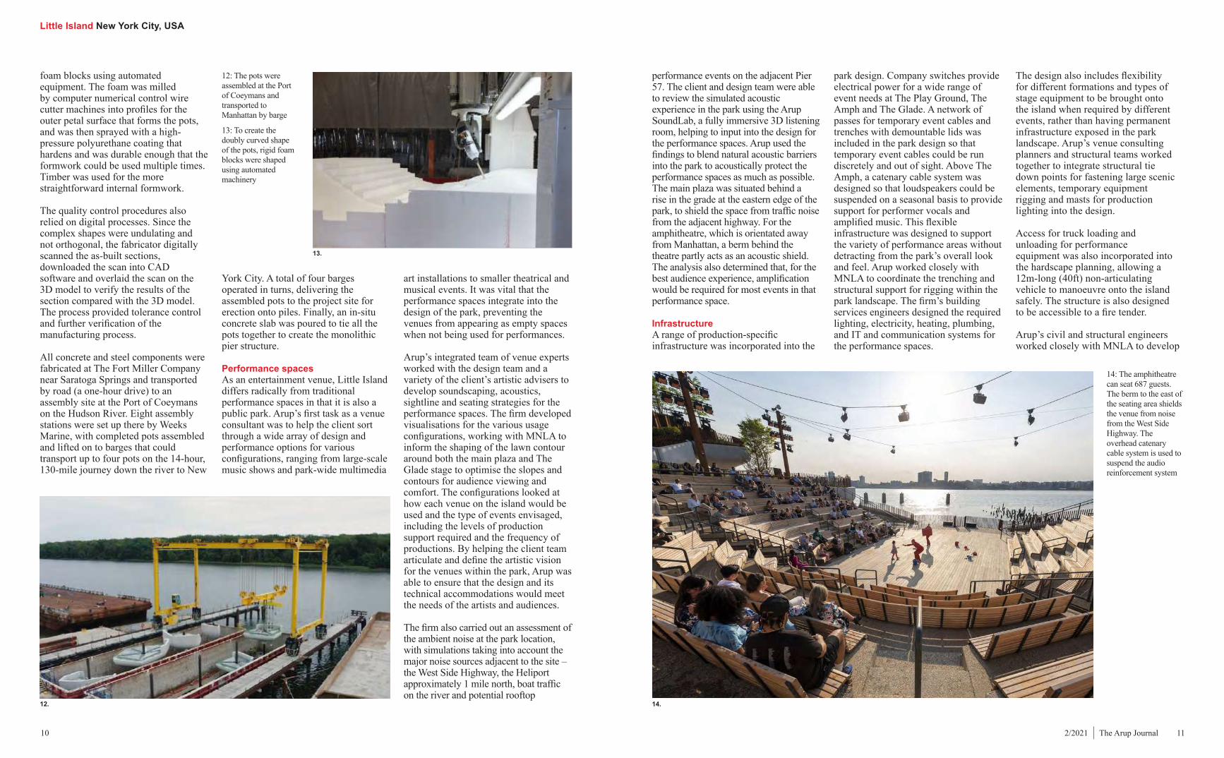
foam blocks using automated equipment. The foam was milled by computer numerical control wire cutter machines into profiles for the outer petal surface that forms the pots, and was then sprayed with a high-pressure polyurethane coating that hardens and was durable enough that the formwork could be used multiple times. Timber was used for the more straightforward internal formwork.
The quality control procedures also relied on digital processes. Since the complex shapes were undulating and not orthogonal, the fabricator digitally scanned the as-built sections, downloaded the scan into CAD software and overlaid the scan on the 3D model to verify the results of the section compared with the 3D model. The process provided tolerance control and further verification of the manufacturing process.
All concrete and steel components were fabricated at The Fort Miller Company near Saratoga Springs and transported by road (a one-hour drive) to an assembly site at the Port of Coeymans on the Hudson River. Eight assembly stations were set up there by Weeks Marine, with completed pots assembled and lifted on to barges that could transport up to four pots on the 14-hour, 130-mile journey down the river to New
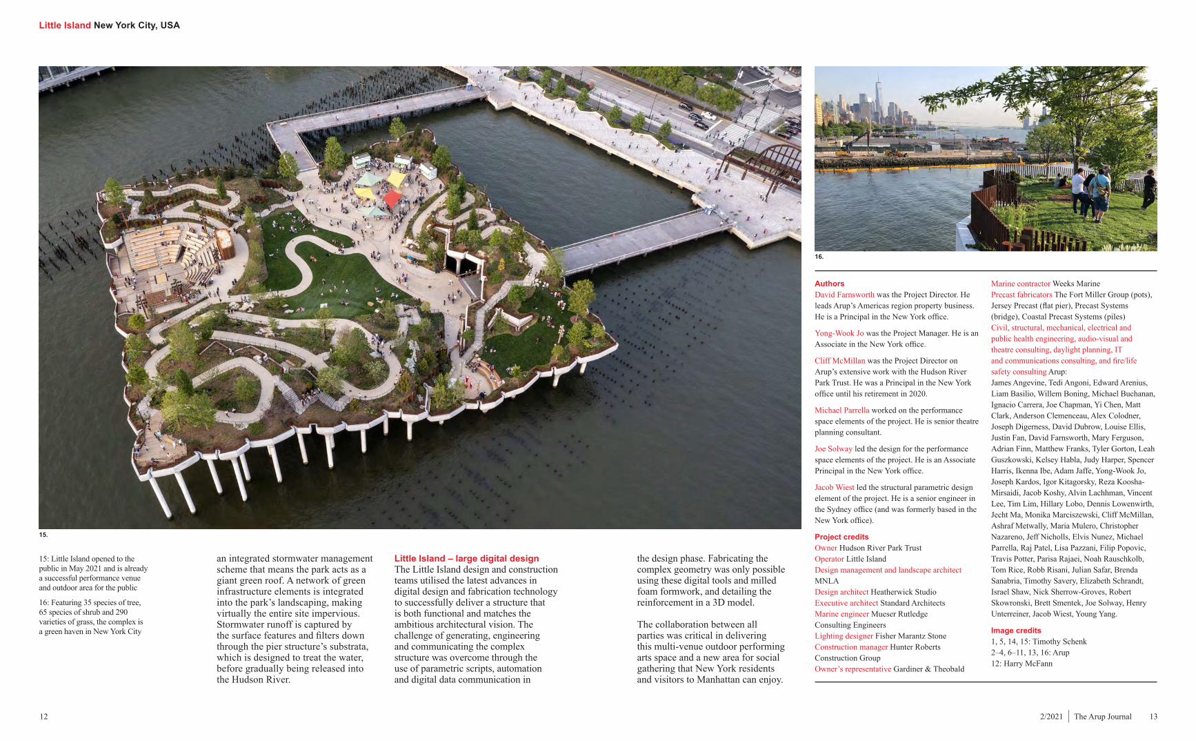
performance events on the adjacent Pier 57. The client and design team were able to review the simulated acoustic experience in the park using the Arup SoundLab, a fully immersive 3D listening room, helping to input into the design for the performance spaces. Arup used the findings to blend natural acoustic barriers into the park to acoustically protect the performance spaces as much as possible. The main plaza was situated behind a rise in the grade at the eastern edge of the park, to shield the space from traffic noise from the adjacent highway. For the amphitheatre, which is orientated away from Manhattan, a berm behind the theatre partly acts as an acoustic shield. The analysis also determined that, for the best audience experience, amplification would be required for most events in that performance space.
Infrastructure A range of production-specific infrastructure was incorporated into the
12: The pots were assembled at the Port of Coeymans and transported to Manhattan by barge
13: To create the doubly curved shape of the pots, rigid foam blocks were shaped using automated machinery
art installations to smaller theatrical and musical events. It was vital that the performance spaces integrate into the design of the park, preventing the venues from appearing as empty spaces when not being used for performances.
Arup’s integrated team of venue experts worked with the design team and a variety of the client’s artistic advisers to develop soundscaping, acoustics, sightline and seating strategies for the performance spaces. The firm developed visualisations for the various usage configurations, working with MNLA to inform the shaping of the lawn contour around both the main plaza and The Glade stage to optimise the slopes and contours for audience viewing and comfort. The configurations looked at how each venue on the island would be used and the type of events envisaged, including the levels of production support required and the frequency of productions. By helping the client team articulate and define the artistic vision for the venues within the park, Arup was able to ensure that the design and its technical accommodations would meet the needs of the artists and audiences.
The firm also carried out an assessment of the ambient noise at the park location, with simulations taking into account the major noise sources adjacent to the site – the West Side Highway, the Heliport approximately 1 mile north, boat traffic on the river and potential rooftop
park design. Company switches provide electrical power for a wide range of event needs at The Play Ground, The Amph and The Glade. A network of passes for temporary event cables and trenches with demountable lids was included in the park design so that temporary event cables could be run discretely and out of sight. Above The Amph, a catenary cable system was designed so that loudspeakers could be suspended on a seasonal basis to provide support for performer vocals and amplified music. This flexible infrastructure was designed to support the variety of performance areas without detracting from the park’s overall look and feel. Arup worked closely with MNLA to coordinate the trenching and structural support for rigging within the park landscape. The firm’s building services engineers designed the required lighting, electricity, heating, plumbing, and IT and communication systems for the performance spaces.
York City. A total of four barges operated in turns, delivering the assembled pots to the project site for erection onto piles. Finally, an in-situ concrete slab was poured to tie all the pots together to create the monolithic pier structure.
Performance spacesAs an entertainment venue, Little Island differs radically from traditional performance spaces in that it is also a public park. Arup’s first task as a venue consultant was to help the client sort through a wide array of design and performance options for various configurations, ranging from large-scale music shows and park-wide multimedia
The design also includes flexibility for different formations and types of stage equipment to be brought onto the island when required by different events, rather than having permanent infrastructure exposed in the park landscape. Arup’s venue consulting planners and structural teams worked together to integrate structural tie down points for fastening large scenic elements, temporary equipment rigging and masts for production lighting into the design.
Access for truck loading and unloading for performance equipment was also incorporated into the hardscape planning, allowing a 12m-long (40ft) non-articulating vehicle to manoeuvre onto the island safely. The structure is also designed to be accessible to a fire tender.
Arup’s civil and structural engineers worked closely with MNLA to develop
12.
13.
14.
14: The amphitheatre can seat 687 guests. The berm to the east of the seating area shields the venue from noise from the West Side Highway. The overhead catenary cable system is used to suspend the audio reinforcement system
Little Island New York City, USA
12 132/2021 | The Arup Journal
Authors David Farnsworth was the Project Director. He leads Arup’s Americas region property business. He is a Principal in the New York office.
Yong-Wook Jo was the Project Manager. He is an Associate in the New York office.
Cliff McMillan was the Project Director on Arup’s extensive work with the Hudson River Park Trust. He was a Principal in the New York office until his retirement in 2020.
Michael Parrella worked on the performance space elements of the project. He is senior theatre planning consultant.
Joe Solway led the design for the performance space elements of the project. He is an Associate Principal in the New York office.
Jacob Wiest led the structural parametric design element of the project. He is a senior engineer in the Sydney office (and was formerly based in the New York office).
Project creditsOwner Hudson River Park TrustOperator Little IslandDesign management and landscape architect MNLADesign architect Heatherwick StudioExecutive architect Standard Architects Marine engineer Mueser Rutledge Consulting EngineersLighting designer Fisher Marantz StoneConstruction manager Hunter Roberts Construction GroupOwner’s representative Gardiner & Theobald
Marine contractor Weeks MarinePrecast fabricators The Fort Miller Group (pots), Jersey Precast (flat pier), Precast Systems (bridge), Coastal Precast Systems (piles)Civil, structural, mechanical, electrical and public health engineering, audio-visual and theatre consulting, daylight planning, IT and communications consulting, and fire/life safety consulting Arup:James Angevine, Tedi Angoni, Edward Arenius, Liam Basilio, Willem Boning, Michael Buchanan, Ignacio Carrera, Joe Chapman, Yi Chen, Matt Clark, Anderson Clemenceau, Alex Colodner, Joseph Digerness, David Dubrow, Louise Ellis, Justin Fan, David Farnsworth, Mary Ferguson, Adrian Finn, Matthew Franks, Tyler Gorton, Leah Guszkowski, Kelsey Habla, Judy Harper, Spencer Harris, Ikenna Ibe, Adam Jaffe, Yong-Wook Jo, Joseph Kardos, Igor Kitagorsky, Reza Koosha-Mirsaidi, Jacob Koshy, Alvin Lachhman, Vincent Lee, Tim Lim, Hillary Lobo, Dennis Lowenwirth, Jecht Ma, Monika Marciszewski, Cliff McMillan, Ashraf Metwally, Maria Mulero, Christopher Nazareno, Jeff Nicholls, Elvis Nunez, Michael Parrella, Raj Patel, Lisa Pazzani, Filip Popovic, Travis Potter, Parisa Rajaei, Noah Rauschkolb, Tom Rice, Robb Risani, Julian Safar, Brenda Sanabria, Timothy Savery, Elizabeth Schrandt, Israel Shaw, Nick Sherrow-Groves, Robert Skowronski, Brett Smentek, Joe Solway, Henry Unterreiner, Jacob Wiest, Young Yang.
Image credits1, 5, 14, 15: Timothy Schenk2–4, 6–11, 13, 16: Arup12: Harry McFann
15: Little Island opened to the public in May 2021 and is already a successful performance venue and outdoor area for the public
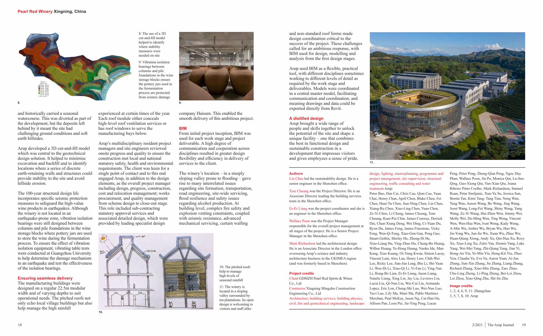
16: Featuring 35 species of tree, 65 species of shrub and 290 varieties of grass, the complex is a green haven in New York City
the design phase. Fabricating the complex geometry was only possible using these digital tools and milled foam formwork, and detailing the reinforcement in a 3D model.
The collaboration between all parties was critical in delivering this multi-venue outdoor performing arts space and a new area for social gathering that New York residents and visitors to Manhattan can enjoy.
an integrated stormwater management scheme that means the park acts as a giant green roof. A network of green infrastructure elements is integrated into the park’s landscaping, making virtually the entire site impervious. Stormwater runoff is captured by the surface features and filters down through the pier structure’s substrata, which is designed to treat the water, before gradually being released into the Hudson River.
Little Island – large digital design The Little Island design and construction teams utilised the latest advances in digital design and fabrication technology to successfully deliver a structure that is both functional and matches the ambitious architectural vision. The challenge of generating, engineering and communicating the complex structure was overcome through the use of parametric scripts, automation and digital data communication in
15.
16.

Pearl Red Winery Xingning, China
14 152/2021 | The Arup Journal
1: The Pearl Red Winery is located in a valley in the countryside in Guangdong Province
2: The winery utilises the traditional Hakka brewing process, which is undertaken by hand, as well as more modern technological processes
1. 2.
A contemporary design that celebrates traditional wine manufacturing and local architectureAuthors Lin Chen, Tom Cheung, Er-Er Liang, Wallace Poon, Mark Richardson
Designing for the traditional with a cutting edge
Located outside of the city of Xingning in Guangdong province, the Pearl Red Winery is a traditional Chinese rice wine factory for a family-owned exclusive brand. Serving both as a production facility and a visitor centre, the winery is nestled in a valley and ringed by tea plantations. As well as traditional baijiu white rice spirit, the Pearl Red range manufactured in the winery includes Hakka yellow wine, and health wine produced for both the local Chinese and expanding international markets.
The client chose a location that would draw visitors to this beautiful countryside area and wanted a welcoming facility that could showcase the traditional winemaking process while also reflecting the local architecture. The facility replaced the previous urban factory located 20km away and Arup’s involvement began from the first master planning of the 120,000m2 site. The firm was commissioned to draw up a feasibility study for the development and, starting from first principles, mapped out the production processes and determined
the maximum volume of wine that could be produced at the facility.
The new winery retains the traditional Chinese Hakka brewing process, which is undertaken by hand, while also incorporating high-tech sustainable manufacturing processes. These automated modern methods ensure high health, safety and environmental protection standards by effectively managing the potentially dangerous nature of some of the substances involved in the production process.
The facility is centred around the multi-storey visitor building, with the entire complex arranged along a pedestrian visitor path. In total, there are 13 buildings including offices, a dormitory, six production blocks (manufacturing approximately 19.8 million bottles/9,900 tonnes of wine per year) and three wine storage blocks, with an overall gross floor area of 150,000m².
Arup engaged a wide range of staff on the project, principally from the Shenzhen, Shanghai and Hong Kong offices, but with additional support from London and Milan. The team also worked with local design institutes, including a rice winemaking process specialist. It spent over seven years on the design and
Pearl Red Winery Xingning, China
16 172/2021 | The Arup Journal
Arup’s design set the facility out so that the natural landscape shields the buildings from higher wind speed areas. The packaging plant building is located at the rear to avoid winter primary winds. The summer primary wind channels exhaust air from the waste treatment plant away from other buildings. The building orientation and façade were also adjusted according to sunpath and solar radiation to minimise heat gain.
The building services design was driven by three factors. First, to achieve an almost cleanroom-level internal condition in order to meet modern food safety management processes and avoid any risk of contamination, Arup designed mock-ups for mould-resisting materials, with tests carried out in the client’s old factory over 12 months to ensure mould was not an issue. Other features include a very early fire warning system, a foam-water deluge system, explosion-proof design, dual exhausting and local humidification/heating.
Second, to minimise resource usage, in particular energy and water, passive building design methods were implemented, such as rooflights. A heat recovery device was installed at the flue gas outlet of the steam boiler. This uses the high temperature from the flue gas as the preheat source for the boiler, at the same time lowering the exhaust gas temperature from over 200°C to below 170°C. This reduces heat loss in the boiler and improves its thermal efficiency by 7%. Along with energy
every day, with 100% of this water used for toilet flushing and site irrigation.
The annual production of vinasse, a byproduct from wine manufacturing that includes both solids and liquids, comes to 20,040 tonnes. This is 100% recycled, with the water also used for toilet flushing and irrigation and the dried vinasse reused as feed in local farms.
The design result is a state-of-the-art environment that not only fulfils wine production process needs but also meets the highly stringent China Green Building Label (two-star A) codes (for the hub building) plus ISO 22000, Hazard Analysis and Critical Control Point, and Good Manufacturing Practices certification for the winery. The hub building is on target to achieve LEED-NC silver and China Green Building Label certification, and the Chinese rice wine distillery building block is due to be certified LEED-NC.
Protecting beauty and valueThe site is beautiful but technically challenging – it is 1km long from end to end with a 40m overall height difference and ranges from 70m to 200m in width. A key driver for the development was to follow the lie of the land, not only to reduce the amount of excavation needed and achieve sustainability credits but also to minimise the impact of construction on the beauty of the valley, which is surrounded by tea plantations (which attracted the client to the site in the first place). The valley is downhill from a lake
performance optimisation, a full building management system allows the client to achieve the best internal environment and air quality for premium wine production while minimising energy use.
Third, to minimise usage and treatment of any products in the winemaking process, in particular water, before release into the public realm, in order to meet and – where possible – exceed local regulations.
For example, an internal circulation anaerobic reactor, pulsed anaerobic reactor and biological aerated filter are all used to ensure the wastewater discharge meets local standards. The water treatment system is designed to process 1,300m3/day of supply water, 1,000m3/day of wastewater and 240m3/day of pure water. Furthermore, around 90 tonnes of wastewater is discharged from the reverse osmosis water treatment system
construction of the complex, drawing on the full breadth of its expertise from architecture to structural, geotechnical and building services engineering, project management, water treatment and process design, and site supervision. This total design approach was able to unlock the potential of the winery’s beautiful location.
The facility merges traditional processes with modern technology and allows visitors to fully explore the winemaking process. The design meets the high standards of environmental control requirements, reducing energy consumption and emissions to provide a sustainable contemporary manufacturing facility.
Architectural traditionPearl Red originated in Meizhou, the capital city of the Hakka people, and the client was keen to echo its Hakka origin in the winery’s architecture. Arup’s response was a design that strongly reflects the location and culture but does so in a completely modern manner. The architecture team drew on two significant Hakka architectural traditions: the South China village vernacular of densely packed simple rectangular buildings with richly expressed pitched roofs and simple planar walls, and the UNESCO World Heritage-listed tulou (roundhouse buildings), a traditional communal residence of Hakka people in nearby Fujian Province. The winery architecture takes these two traditional forms and reinterprets them for a different function and era. While tulou were originally defensive, walled, private residential buildings, the winery is, in contrast, open and actively welcoming to visitors.
Visitor experienceThe circular hub building, with its three floors and mezzanine level, was placed at the centre of the long and narrow site, with production facilities stretching out to the north and south of the hub. The building is inspired by the architectural style of a Hakka walled village and houses a celebration of Hakka winemaking with a two-storey museum, lecture theatre, restaurant, shop and
cookery school, as well as administrative areas and testing laboratories.
The building’s landscaped central courtyard is the heart of the campus. It has an open ground floor, with the arcade around the open upper floors designed to create a cool and shaded environment, drawing gentle breezes through the building and providing a respite from the hot and humid Guangdong summers. The courtyard provides 360° views out onto the adjacent hills, helping the building blend into the environment, dissolving the boundaries between inside and out and providing picturesque vistas.
From the museum on the first floor, a high-level visitor walkway extends north and south. This ‘spine’ route passes by and through each of the manufacturing buildings, giving visitors a unique window into the wine production process. This walkway is level to cater for those
with mobility issues, but the external ground level falls away dramatically. This means that while visitors enter at first floor level, at the end of the southern route they are at third floor level and able to enjoy views of the surrounding hills.
A carefully calibrated environmentWine production at the Pearl Red Winery is carried out by hand using centuries-old methods and the skill in shaping the wines’ unique taste comes from the precise choice of ingredients, attention to detail and achieving a contamination-free, tightly controlled internal environment. As contamination could affect taste and quality, the various wine products are passed between buildings via grade 316L stainless steel pipes, which are located above ground to facilitate routine maintenance. The pipework travels along the external utility bridge that connects most of the workshops and the warehouse.
3: The hub has a landscaped central courtyard and an open ground floor
4: A high-level walkway leads from the museum through all the manufacturing buildings
5: Arup used CFD analysis to design the building orientation and faҫades, adjusting for the sunpath to minimise heat gain
6: The internal environment is tightly controlled so that it is contamination-free
7: The hub includes a two-storey museum, lecture theatre and offices
4.
3.
6.
5.
7.
Pearl Red Winery Xingning, China
18 192/2021 | The Arup Journal
and historically carried a seasonal watercourse. This was diverted as part of the development, but the deposits left behind by it meant the site had challenging ground conditions and soft earth hillsides.
Arup developed a 3D cut-and-fill model which was central to the geotechnical design solution. It helped to minimise excavation and backfill and to identify locations where a series of discrete earth-retaining walls and structures could provide stability to the site and avoid hillside erosion.
The 100-year structural design life incorporates specific seismic protection measures to safeguard the high-value wine products in earthquakes. Although the winery is not located in an earthquake-prone zone, vibration isolation bearings were still designed between columns and pile foundations in the wine storage blocks where pottery jars are used to store the wine during the fermentation process. To ensure the effect of vibration isolation equipment, vibrating table tests were conducted at Guangzhou University to help determine the damage mechanism in an earthquake and test the effectiveness of the isolation bearings.
Ensuring seamless deliveryThe manufacturing buildings were designed on a regular 22.5m modular width and of varying depths to suit operational needs. The pitched roofs not only echo local village buildings but also help manage the high rainfall
experienced at certain times of the year. Each roof module either conceals high-level roof ventilation services or has roof windows to serve the manufacturing bays below.
Arup’s multidisciplinary resident project managers and site engineers reviewed onsite progress and quality to ensure the construction met local and national statutory safety, health and environmental requirements. The client was keen for a single point of contact and to this end engaged Arup, in addition to the design elements, as the overall project manager including design, progress, construction, cost and relocation management; works procurement; and quality management from scheme design to close-out stage. This role included sub-contracting statutory approval services and associated detailed design, which were provided by leading specialist design
and non-standard roof forms made design coordination critical to the success of the project. These challenges called for an ambitious response, with BIM used for design, modelling and analysis from the first design stages.
Arup used BIM as a flexible, practical tool, with different disciplines sometimes working to different levels of detail as required by the work stage and deliverables. Models were coordinated in a central master model, facilitating communication and coordination, and meaning drawings and data could be exported directly from Revit.
A distilled design Arup brought a wide range of people and skills together to unlock the potential of the site and shape a unique facility – one that combines the best in functional design and sustainable construction in a development that impresses visitors and gives employees a sense of pride.
company Haisum. This enabled the smooth delivery of this ambitious project.
BIMFrom initial project inception, BIM was used for each work stage and project deliverable. A high degree of communication and cooperation across disciplines resulted in greater design flexibility and efficiency in delivery of services to the client.
The winery’s location – in a steeply sloping valley prone to flooding – gave rise to many interrelated issues regarding site formation, transportation, road engineering, site-wide servicing, flood resilience and safety issues regarding alcohol production. At building level, complex fire safety and explosion venting constraints, coupled with seismic resistance, advanced mechanical servicing, curtain walling
11.
10.
Authors Lin Chen led the sustainability design. He is a senior engineer in the Shenzhen office.
Tom Cheung was the Project Director. He is an Associate Director leading the building services team in the Shenzhen office.
Er-Er Liang was the project coordinator and she is an engineer in the Shenzhen office.
Wallace Poon was the Project Manager responsible for the overall project management at all stages of the project. He is a Senior Project Manager in the Shenzhen office.
Mark Richardson led the architectural design. He is an Associate Director in the London office overseeing Arup’s science and industry architecture business in the UKIMEA region (and was formerly based in Shenzhen).
Project creditsClient GDMZH Pearl Red Spirits & Wines Co., LtdContractor Xingning Mingzhu Construction Engineering Co., LtdArchitecture, building services, building physics, civil, fire and geotechnical engineering, landscape
design, lighting, masterplanning, programme and project management, site supervision, structural engineering, traffic consulting and water treatment Arup:Peter Bao, Dan Cai, Chris Cao, Qian Cao, Yuan Chai, Henry Chan, April Chen, Blake Chen, Fei Chen, Huai-Yu Chen, Jian-Ning Chen, Lin Chen, Xiang-Ru Chen, Xiao-Ling Chen, Yuan Chen, Ze-Yi Chen, Li Cheng, James Cheung, Tom Cheung, Kam-Pui Chin, James Conway, Derrick Dai, Chun-Xiang Deng, Wei Ding, Ci-Yuan Du, Ryon Du, James Feng, James Finestone, Vicky Feng, Wen-Qi Feng, Xiao-Gen Gan, Peng Gao, Stuart Gethin, Shirley He, Zhong-Di He, Xiao-Liang Hu, Ying-Zhao Hu, Cheng-Bo Huang, Wilbur Huang, Ye-Hong Huang, Naoko Ide, Man Kang, Xiao Kuang, Oi-Yung Kwan, Simon Lacey, Vincent Lam, Alex Lan, Henry Law, Chih-Wei Lee, Ricky Lee, Jian-Jun Leng, Bin Li, Shi-Yuan Li, Wen-Di Li, Xiao-Qi Li, Yi-Fan Li, Ying-Yan Li, Hong-Bo Lian, Er-Er Liang, Jason Liang, Natalie Liang, Xing Lin, Jay Liu, Leviews Liu, Lucia Liu, Qi-Nan Liu, Wei-Cai Liu, Armando Lopez, Eric Lou, Cheng-Shi Luo, Wei-Nuo Luo, Yuvi Luo, Lily Ma, Mani Ma, Pablo Martinez Merchan, Paul McKay, Jason Ng, Cai-Dan Ou, Allison Pan, Leon Pei, Jia-Ying Peng, Lucas
Peng, Peter Peng, Zheng-Qian Peng, Ngoc Duy Phan, Wallace Poon, Jin Pu, Monica Qin, Lu-Suo Qing, Guo-Xiong Qiu, Yun-Xian Qiu, Joana Ribeiro Pinto Coelho, Mark Richardson, Samuel Ruan, Petar Smiljanic, Xun-Yu Su, Jessica Sun, Benita Tan, Kimi Tang, Tang Tian, Neng Wan, Teng Wan, Anson Wang, Bo Wang, Jing Wang, Joost Wang, Long-Fei Wang, Shiny Wang, Yang Wang, Ze-Xi Wang, Hui-Zhen Wen, Jimmy Wei, Molly Wei, De-Ming Wen, Ting Weng, Vincent Wen, Wen-Hua Wen, Ivan Wong, Kady Wong, A-Min Wu, Amber Wu, Bryan Wu, Hao Wu, Jia-Yong Wu, Jun-Jie Wu, Xuan Wu, Zhuo Wu, Huan-Qiang Xiong, Andy Xu, Qin-Hua Xu, Roxy Xu, Xiao-Ling Xu, Zulei Yan, Dennis Yang, Lake Yang, Wei-Mei Yang, Zhi-Qiang Yang, Jian Yi, Hong-An Yin, Ye-Min Yin, Hong-Kit Yiu, Zhuo You, Claudia Yu, Eva Yu, Aaron Yuan, Ai-Jun Zhang, Jian-Xin Zhang, Jie Zhang, Liang Zhang, Richard Zhang, Xiao-Min Zhang, Zarc Zhao, Chu-Ling Zheng, Li-Ping Zheng, Bei-Lei Zhou, Lei Zhou, Xiao-Qing Zhu, Shi-Jie Zhu.
Image credits1, 2, 4, 6, 9, 11: Zhangchao3, 5, 7, 8, 10: Arup
10: The pitched roofs help to manage high levels of seasonal rainfall
11: The winery is located in a sloping valley surrounded by tea plantations. Its open design is welcoming to visitors and staff alike
8: The use of a 3D cut-and-fill model helped to identify where stability measures were needed on site
9: Vibration isolation bearings between columns and pile foundations in the wine storage blocks ensure the pottery jars used in the fermentation process are protected from seismic damage
8. 9.
South East of Scotland Transport Partnership Strategic Network UK
20 212/2021 | The Arup Journal
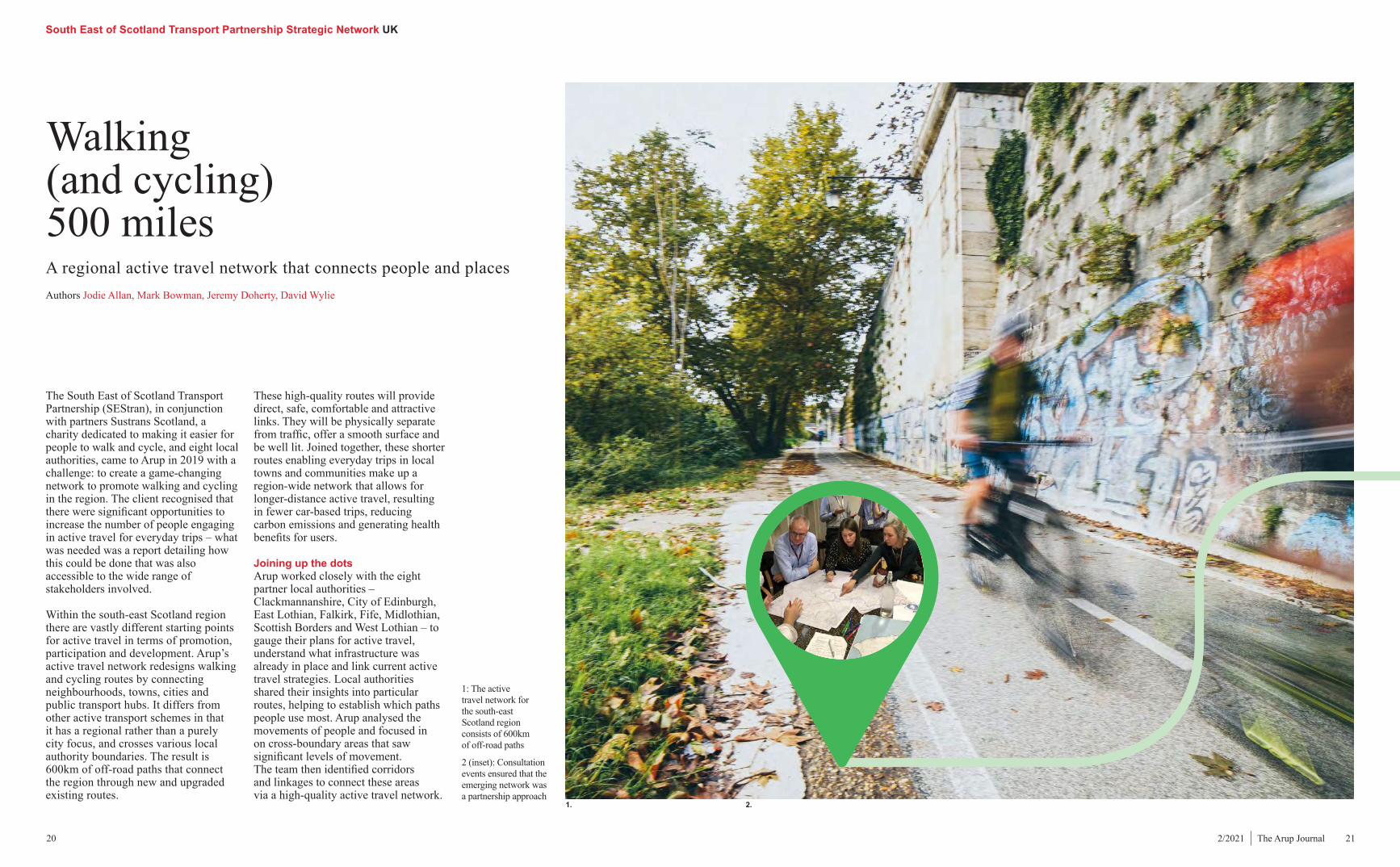
1: The active travel network for the south-east Scotland region consists of 600km of off-road paths
2 (inset): Consultation events ensured that the emerging network was a partnership approach
The South East of Scotland Transport Partnership (SEStran), in conjunction with partners Sustrans Scotland, a charity dedicated to making it easier for people to walk and cycle, and eight local authorities, came to Arup in 2019 with a challenge: to create a game-changing network to promote walking and cycling in the region. The client recognised that there were significant opportunities to increase the number of people engaging in active travel for everyday trips – what was needed was a report detailing how this could be done that was also accessible to the wide range of stakeholders involved.
Within the south-east Scotland region there are vastly different starting points for active travel in terms of promotion, participation and development. Arup’s active travel network redesigns walking and cycling routes by connecting neighbourhoods, towns, cities and public transport hubs. It differs from other active transport schemes in that it has a regional rather than a purely city focus, and crosses various local authority boundaries. The result is 600km of off-road paths that connect the region through new and upgraded existing routes.
Walking (and cycling) 500 milesA regional active travel network that connects people and placesAuthors Jodie Allan, Mark Bowman, Jeremy Doherty, David Wylie
1. 2.
These high-quality routes will provide direct, safe, comfortable and attractive links. They will be physically separate from traffic, offer a smooth surface and be well lit. Joined together, these shorter routes enabling everyday trips in local towns and communities make up a region-wide network that allows for longer-distance active travel, resulting in fewer car-based trips, reducing carbon emissions and generating health benefits for users.
Joining up the dots Arup worked closely with the eight partner local authorities – Clackmannanshire, City of Edinburgh, East Lothian, Falkirk, Fife, Midlothian, Scottish Borders and West Lothian – to gauge their plans for active travel, understand what infrastructure was already in place and link current active travel strategies. Local authorities shared their insights into particular routes, helping to establish which paths people use most. Arup analysed the movements of people and focused in on cross-boundary areas that saw significant levels of movement. The team then identified corridors and linkages to connect these areas via a high-quality active travel network.
South East of Scotland Transport Partnership Strategic Network UK
22 232/2021 | The Arup Journal
In auditing the 250km of on- and off-road routes, the team discovered a vast array of high-quality routes already in place. However, some of these need improved lighting, maintenance and safe road crossing points to be included in the strategic network. Some of the other characteristics taken into consideration were local attractors (employment, education, leisure, retail), surface quality, pedestrian and cyclist infrastructure such as benches and cycle parking, footway/cycleway width, cyclist and pedestrian flow, signage, and day and night-time safety.
All-inclusive data analysis Gathering the right data at the right time from eight local authorities was a challenge. Each council is responsible for its own network, so Arup stepped in to create linkages across local authority borders for the overall network. The team had to ensure the data was in a consistent format to inform the analysis and evaluation of the network.
They created a geospatial database collating the existing research and active travel links and encompassing current public transport hubs and major bus and rail links. Some regions, such as Clackmannanshire, had their planned network for the next five years mapped, so Arup was able to incorporate it with the other proposed local networks. Together, these influenced the design of the new strategic regional network. Arup
Authors Jodie Allan led the stakeholder engagement process. She is a transport planner in the Glasgow office.
Mark Bowman was the Project Manager. He leads Arup’s active travel team in Scotland, Northern Ireland and North-East England and is an Associate in the Edinburgh office.
Jeremy Doherty led the digital design. He is an Associate in the Edinburgh office.
David Wylie led the visual communication design. He is a graphic designer in the Edinburgh office.
Project creditsClient SEStranTown planning and transport consulting Arup:Jodie Allan, Mark Bowman, Matthew Cook, Jeremy Doherty, Gordon Diamond, Jamie Smith, Chris Stewart, Dan Tuck, David Wylie.
Image credits1: Umit Yildirim/Unsplash2–5: Arup
The overall network is large – but the expectation is not that everyone will cycle 20km+ to work every day. A core part of the project was connecting the walking and cycling routes with park and rides, train stations and other transport hubs to enable active travel to be part of longer-distance public transport trips. For example, in Edinburgh there are many distances of 5–10km that are easily cyclable, so Arup looked to connect these together by posing the question: what would it take to get people to cycle or walk these distances? The routes will help form multimodal journeys for people seeking direct routes for walking and cycling.
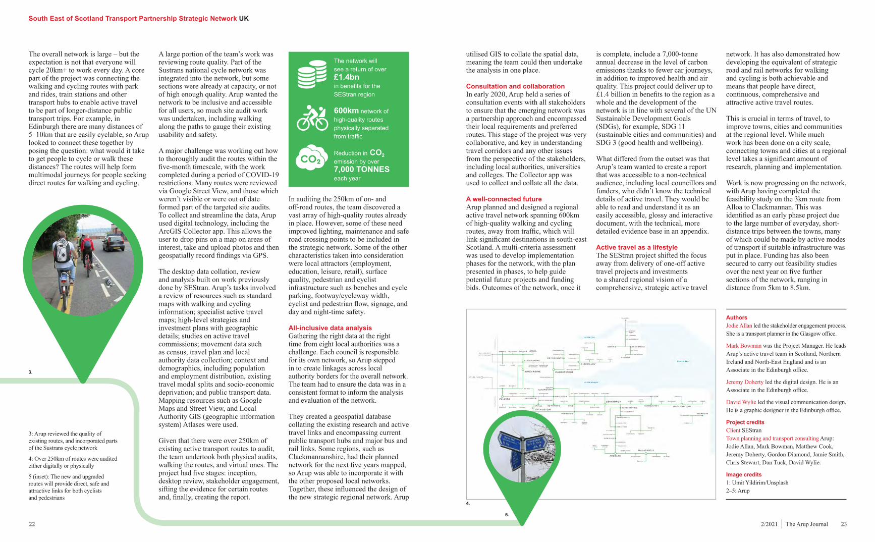
3: Arup reviewed the quality of existing routes, and incorporated parts of the Sustrans cycle network
4: Over 250km of routes were audited either digitally or physically
5 (inset): The new and upgraded routes will provide direct, safe and attractive links for both cyclists and pedestrians
A large portion of the team’s work was reviewing route quality. Part of the Sustrans national cycle network was integrated into the network, but some sections were already at capacity, or not of high enough quality. Arup wanted the network to be inclusive and accessible for all users, so much site audit work was undertaken, including walking along the paths to gauge their existing usability and safety.
A major challenge was working out how to thoroughly audit the routes within the five-month timescale, with the work completed during a period of COVID-19 restrictions. Many routes were reviewed via Google Street View, and those which weren’t visible or were out of date formed part of the targeted site audits. To collect and streamline the data, Arup used digital technology, including the ArcGIS Collector app. This allows the user to drop pins on a map on areas of interest, take and upload photos and then geospatially record findings via GPS.
The desktop data collation, review and analysis built on work previously done by SEStran. Arup’s tasks involved a review of resources such as standard maps with walking and cycling information; specialist active travel maps; high-level strategies and investment plans with geographic details; studies on active travel commissions; movement data such as census, travel plan and local authority data collection; context and demographics, including population and employment distribution, existing travel modal splits and socio-economic deprivation; and public transport data. Mapping resources such as Google Maps and Street View, and Local Authority GIS (geographic information system) Atlases were used.
Given that there were over 250km of existing active transport routes to audit, the team undertook both physical audits, walking the routes, and virtual ones. The project had five stages: inception, desktop review, stakeholder engagement, sifting the evidence for certain routes and, finally, creating the report.
utilised GIS to collate the spatial data, meaning the team could then undertake the analysis in one place.
Consultation and collaborationIn early 2020, Arup held a series of consultation events with all stakeholders to ensure that the emerging network was a partnership approach and encompassed their local requirements and preferred routes. This stage of the project was very collaborative, and key in understanding travel corridors and any other issues from the perspective of the stakeholders, including local authorities, universities and colleges. The Collector app was used to collect and collate all the data.
A well-connected futureArup planned and designed a regional active travel network spanning 600km of high-quality walking and cycling routes, away from traffic, which will link significant destinations in south-east Scotland. A multi-criteria assessment was used to develop implementation phases for the network, with the plan presented in phases, to help guide potential future projects and funding bids. Outcomes of the network, once it
is complete, include a 7,000-tonne annual decrease in the level of carbon emissions thanks to fewer car journeys, in addition to improved health and air quality. This project could deliver up to £1.4 billion in benefits to the region as a whole and the development of the network is in line with several of the UN Sustainable Development Goals (SDGs), for example, SDG 11 (sustainable cities and communities) and SDG 3 (good health and wellbeing).
What differed from the outset was that Arup’s team wanted to create a report that was accessible to a non-technical audience, including local councillors and funders, who didn’t know the technical details of active travel. They would be able to read and understand it as an easily accessible, glossy and interactive document, with the technical, more detailed evidence base in an appendix.
Active travel as a lifestyleThe SEStran project shifted the focus away from delivery of one-off active travel projects and investments to a shared regional vision of a comprehensive, strategic active travel
network. It has also demonstrated how developing the equivalent of strategic road and rail networks for walking and cycling is both achievable and means that people have direct, continuous, comprehensive and attractive active travel routes.
This is crucial in terms of travel, to improve towns, cities and communities at the regional level. While much work has been done on a city scale, connecting towns and cities at a regional level takes a significant amount of research, planning and implementation.
Work is now progressing on the network, with Arup having completed the feasibility study on the 3km route from Alloa to Clackmannan. This was identified as an early phase project due to the large number of everyday, short-distance trips between the towns, many of which could be made by active modes of transport if suitable infrastructure was put in place. Funding has also been secured to carry out feasibility studies over the next year on five further sections of the network, ranging in distance from 5km to 8.5km.
3.
4.
5.
The network will see a return of over £1.4bn in benefits for the SEStran region
600km network of high-quality routes physically separated from traffic
Reduction in CO2 emission by over 7,000 TONNES each year
Başakşehir Çam and Sakura City Hospital Istanbul, Turkey
24 252/2021 | The Arup Journal
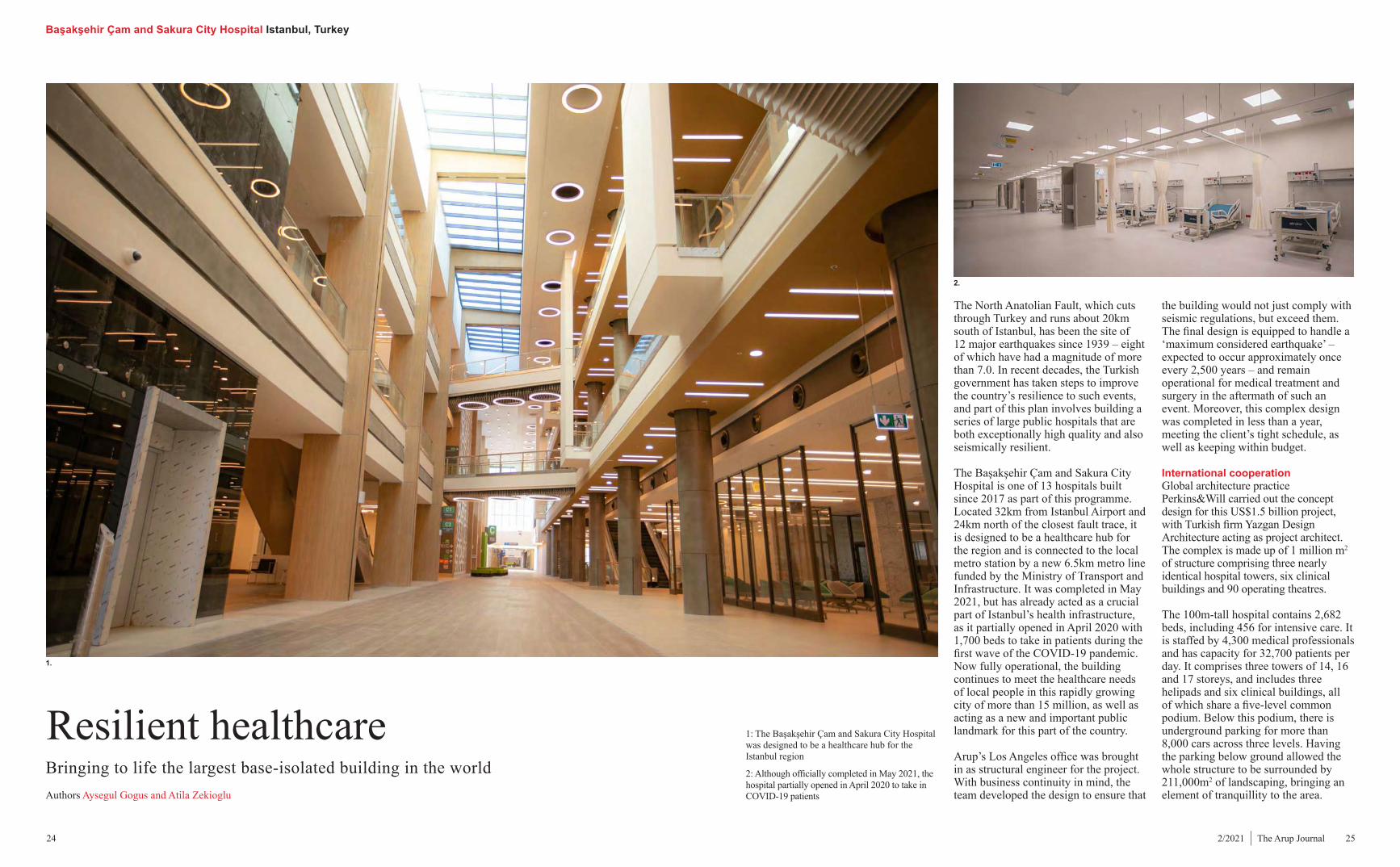
The North Anatolian Fault, which cuts through Turkey and runs about 20km south of Istanbul, has been the site of 12 major earthquakes since 1939 – eight of which have had a magnitude of more than 7.0. In recent decades, the Turkish government has taken steps to improve the country’s resilience to such events, and part of this plan involves building a series of large public hospitals that are both exceptionally high quality and also seismically resilient.
The Başakşehir Çam and Sakura City Hospital is one of 13 hospitals built since 2017 as part of this programme. Located 32km from Istanbul Airport and 24km north of the closest fault trace, it is designed to be a healthcare hub for the region and is connected to the local metro station by a new 6.5km metro line funded by the Ministry of Transport and Infrastructure. It was completed in May 2021, but has already acted as a crucial part of Istanbul’s health infrastructure, as it partially opened in April 2020 with 1,700 beds to take in patients during the first wave of the COVID-19 pandemic. Now fully operational, the building continues to meet the healthcare needs of local people in this rapidly growing city of more than 15 million, as well as acting as a new and important public landmark for this part of the country.
Arup’s Los Angeles office was brought in as structural engineer for the project. With business continuity in mind, the team developed the design to ensure that
the building would not just comply with seismic regulations, but exceed them. The final design is equipped to handle a ‘maximum considered earthquake’ – expected to occur approximately once every 2,500 years – and remain operational for medical treatment and surgery in the aftermath of such an event. Moreover, this complex design was completed in less than a year, meeting the client’s tight schedule, as well as keeping within budget.
International cooperationGlobal architecture practice Perkins&Will carried out the concept design for this US$1.5 billion project, with Turkish firm Yazgan Design Architecture acting as project architect. The complex is made up of 1 million m2 of structure comprising three nearly identical hospital towers, six clinical buildings and 90 operating theatres.
The 100m-tall hospital contains 2,682 beds, including 456 for intensive care. It is staffed by 4,300 medical professionals and has capacity for 32,700 patients per day. It comprises three towers of 14, 16 and 17 storeys, and includes three helipads and six clinical buildings, all of which share a five-level common podium. Below this podium, there is underground parking for more than 8,000 cars across three levels. Having the parking below ground allowed the whole structure to be surrounded by 211,000m2 of landscaping, bringing an element of tranquillity to the area.
Resilient healthcareBringing to life the largest base-isolated building in the world Authors Aysegul Gogus and Atila Zekioglu
1.
2.
1: The Başakşehir Çam and Sakura City Hospital was designed to be a healthcare hub for the Istanbul region
2: Although officially completed in May 2021, the hospital partially opened in April 2020 to take in COVID-19 patients
Başakşehir Çam and Sakura City Hospital Istanbul, Turkey
grid is 8.4m x 8.4m, and the floor-to-floor heights vary from 4m to 6.5m, with the typical floor height being 4.3m. The floor slabs are 250mm thick, with column sizes ranging from 1,200mm x 1,200mm at the base level to 500mm x 500mm supporting the roof. The lateral load-resisting system comprises special reinforced concrete walls that resist 100% of the lateral loads in both orthogonal directions of the building.
Computational analysisIn designing the seismic force-resisting elements of the project, Arup carried out extensive modelling and non-linear time history analysis which simulates the structural impact of an earthquake over time. Traditional seismic design process relies on manual workflows and analysis on local computers, which makes it hard to evaluate and optimise complex structures. In recent years, however, computing technology has improved so that much larger amounts of data can be processed, allowing the analysis of complex or large-scale structures to become more automated and much quicker.
Arup parametrically analysed and evaluated different seismic isolation schemes to help the client select the most efficient seismic isolation system for the building. Using cloud computing and LS-DYNA, the team processed approximately 30 terabytes of data using big-data platforms and converted it to usable information for decision-making
700mm horizontally during an earthquake, which helps to release seismic energy.
Simply meeting local building codes would have been enough to obtain permission for the hospital, but Arup encouraged the client to go above and beyond the basic requirements and think about business continuity after an earthquake, as well as the level of repairs and downtime that a badly damaged hospital would need. The design was therefore not just shaped by the goal of keeping the building standing during an earthquake, but how it should perform after such an event.
The hospital is designed to satisfy the American Society of Civil Engineers’
earthquakes would be separated from the podium with horizontal seismic joints. These joints remove the challenge of backstay effects, i.e. the transfer of the large lateral loads that need to be distributed from the superstructure to the podium walls through the podium diaphragms. On this project, though, use of base isolation reduced the seismic loads imposed on the superstructure by a factor of three and thus eliminated the need for any seismic joints. This allowed the client to make cost savings of approximately US$10 million and reduced the construction schedule by roughly three months.
The hospital has 2,068 seismic isolators and is the largest base-isolated structure in the world. The selection of the isolators was the most crucial element of the design, as these had the most significant impact on the construction cost and schedule, and the resilience of the building against seismic events. Arup studied six different isolation schemes, including ones that employed triple friction pendulum bearings, lead rubber bearings and high damping rubber bearings, arranged in different configurations.
The client ultimately chose the triple friction pendulum bearings based on their performance, cost, and procurement and installation schedule. The isolators selected for the hospital can shift up to
Site investigations conducted by the Geotechnical Engineer of Record, Kilci Mühendislik, concluded that shallow foundations would not be feasible due to the existence of three different soil profiles and the requirement for fill in some locations below the building footprint. Instead, pile foundations were recommended. Arup’s foundation design resulted in the use of 7,500 piles, each 1m in diameter and varying in length between 5m and 30.5m, with approximately 2,000 pile caps in total.
The gravity load-resisting system of the building comprises reinforced concrete slabs and beams supported by in-situ concrete columns. The typical structural
‘immediate occupancy’ seismic performance objective 41, which means it can continue to be operational (including for surgery), with a ‘drift limit’ of 0.5%, under the design basis earthquake and has the ability to be immediately occupied after a ‘very rare’ earthquake event, with a drift limit of 1%. This is partly because the design protects non-structural components of the building – such as the exterior envelope, medical equipment, and the mechanical and plumbing pipes and electrical conduits – by minimising floor accelerations to 0.2g under a maximum considered earthquake event. This means the hospital can continue to provide critical and lifesaving services even after an earthquake, both to existing patients and others who may need urgent treatment following the event.
26 272/2021 | The Arup Journal
The project was funded by two investment firms, Rönesans Holding and Japan-based Sojitz Corporation. This Turkish–Japanese cooperation is reflected in the hospital’s name – çam meaning pine in Turkish and sakura meaning cherry blossom in Japanese. The project was procured under a public–private partnership contract with Turkey’s Ministry of Health.
Seismic engineeringEarthquakes release large amounts of energy that travel through a structure in the form of seismic waves. Use of base isolation generally helps to reduce the seismic forces imposed on superstructures and improves the seismic performance of buildings. With this in mind, the Turkish Ministry of Health has mandated the use of base isolators for new city hospitals in high seismic zones. This design strategy involves using seismic isolators to decouple the structure of a building from its base, which means that when the ground moves under seismic load, the seismic isolators absorb and dissipate energy, allowing the building above to move safely.
Arup was responsible for the design of the base-isolation system, the seismic design of the superstructure and the design of the foundations for Başakşehir Çam and Sakura City Hospital. Typically, a tall building with a large, stiff concrete podium in a location susceptible to
4.
6.
7.5.
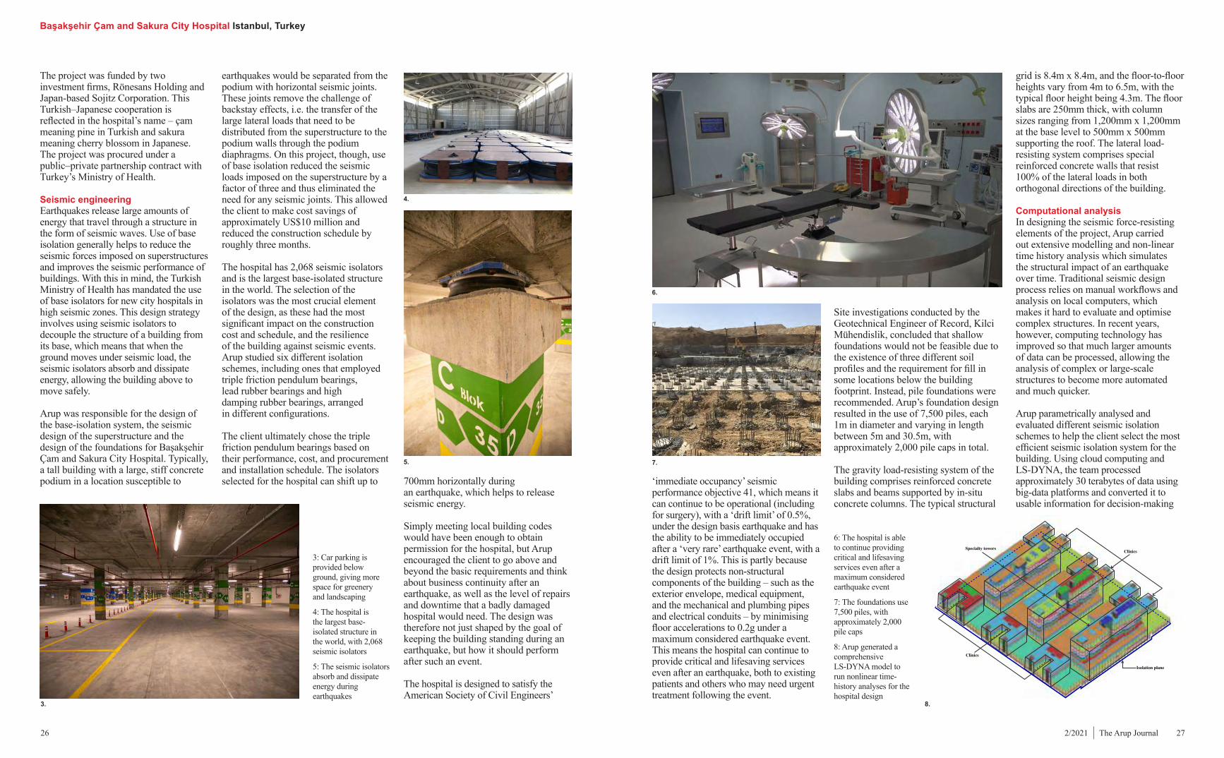
6: The hospital is able to continue providing critical and lifesaving services even after a maximum considered earthquake event
7: The foundations use 7,500 piles, with approximately 2,000 pile caps
8: Arup generated a comprehensive LS-DYNA model to run nonlinear time-history analyses for the hospital design
3: Car parking is provided below ground, giving more space for greenery and landscaping
4: The hospital is the largest base-isolated structure in the world, with 2,068 seismic isolators
5: The seismic isolators absorb and dissipate energy during earthquakes
Specialty towersClinics
Clinics
Isolation plane
8.3.
Başakşehir Çam and Sakura City Hospital Istanbul, Turkey
28 292/2021 | The Arup Journal
modal analysis results and the total concrete quantity of each of the options. These were fed into a database and shared with the client through an interactive web-based platform, allowing the client and stakeholders to partake in devising the best route forward.
A rapid timelineArup started designing the scheme in the second quarter of 2016 and completed it within a year. Construction began on site in 2017 and finished in 32 months. This rapid turnaround was partly the result of the firm’s use of digital technology for the design, but also owed a lot to its efficient management of the project.
With the engineering team based in Arup’s Los Angeles office, the concept architect Perkins&Will operating out of its Washington DC office, the client and the project architect in Ankara, and the site in Istanbul, the project was an exercise in cross-continental coordination. Cloud-based workflows and digital tools helped with this. To navigate the time difference, Arup’s LA team ensured an efficient system of email communication towards the end of their working day, meaning the Turkey-based teams could process and respond to any queries during their working hours, ensuring work would continue to progress. Arup’s Turkish-speaking team members were integral in
on the isolation system. The firm has been developing its methods in this area for over a decade and was able to carry out multiple concurrent analyses. Overall, the team analysed 168 time-history scenarios for the selection of the seismic isolation scheme. Automated analysis model generation and cloud computing significantly shortened the isolation scheme selection process; whereas it would typically have taken approximately seven months, it instead took just two. Evaluation of various seismic isolation schemes allowed the client to view a variety of options and obtain bids from a wide range of vendors.
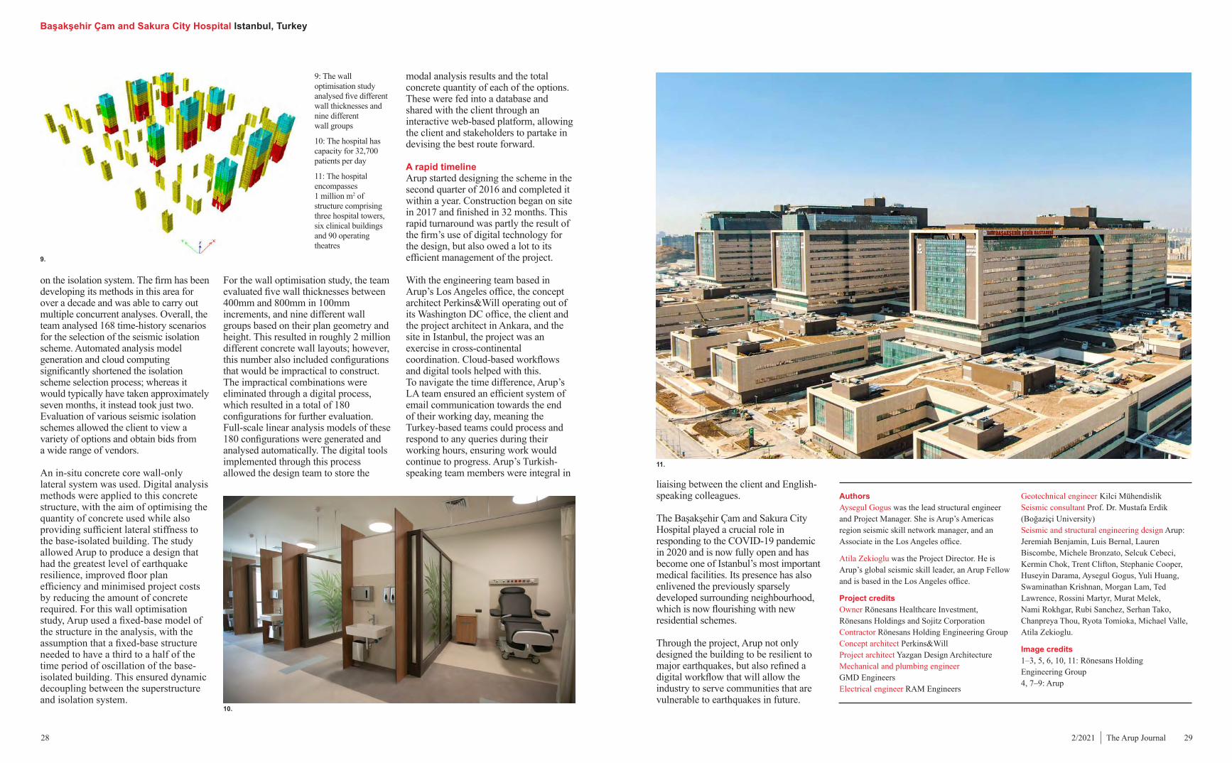
An in-situ concrete core wall-only lateral system was used. Digital analysis methods were applied to this concrete structure, with the aim of optimising the quantity of concrete used while also providing sufficient lateral stiffness to the base-isolated building. The study allowed Arup to produce a design that had the greatest level of earthquake resilience, improved floor plan efficiency and minimised project costs by reducing the amount of concrete required. For this wall optimisation study, Arup used a fixed-base model of the structure in the analysis, with the assumption that a fixed-base structure needed to have a third to a half of the time period of oscillation of the base-isolated building. This ensured dynamic decoupling between the superstructure and isolation system.
For the wall optimisation study, the team evaluated five wall thicknesses between 400mm and 800mm in 100mm increments, and nine different wall groups based on their plan geometry and height. This resulted in roughly 2 million different concrete wall layouts; however, this number also included configurations that would be impractical to construct. The impractical combinations were eliminated through a digital process, which resulted in a total of 180 configurations for further evaluation. Full-scale linear analysis models of these 180 configurations were generated and analysed automatically. The digital tools implemented through this process allowed the design team to store the
AuthorsAysegul Gogus was the lead structural engineer and Project Manager. She is Arup’s Americas region seismic skill network manager, and an Associate in the Los Angeles office.
Atila Zekioglu was the Project Director. He is Arup’s global seismic skill leader, an Arup Fellow and is based in the Los Angeles office.
Project creditsOwner Rönesans Healthcare Investment, Rönesans Holdings and Sojitz Corporation Contractor Rönesans Holding Engineering GroupConcept architect Perkins&WillProject architect Yazgan Design Architecture Mechanical and plumbing engineer GMD EngineersElectrical engineer RAM Engineers
Geotechnical engineer Kilci Mühendislik Seismic consultant Prof. Dr. Mustafa Erdik (Boğaziҫi University)Seismic and structural engineering design Arup:Jeremiah Benjamin, Luis Bernal, Lauren Biscombe, Michele Bronzato, Selcuk Cebeci, Kermin Chok, Trent Clifton, Stephanie Cooper, Huseyin Darama, Aysegul Gogus, Yuli Huang, Swaminathan Krishnan, Morgan Lam, Ted Lawrence, Rossini Martyr, Murat Melek, Nami Rokhgar, Rubi Sanchez, Serhan Tako, Chanpreya Thou, Ryota Tomioka, Michael Valle, Atila Zekioglu.
Image credits1–3, 5, 6, 10, 11: Rönesans Holding Engineering Group 4, 7–9: Arup
9.
10.
11.
9: The wall optimisation study analysed five different wall thicknesses and nine different wall groups
10: The hospital has capacity for 32,700 patients per day
11: The hospital encompasses 1 million m2 of structure comprising three hospital towers, six clinical buildings and 90 operating theatres
liaising between the client and English-speaking colleagues.
The Başakşehir Çam and Sakura City Hospital played a crucial role in responding to the COVID-19 pandemic in 2020 and is now fully open and has become one of Istanbul’s most important medical facilities. Its presence has also enlivened the previously sparsely developed surrounding neighbourhood, which is now flourishing with new residential schemes.
Through the project, Arup not only designed the building to be resilient to major earthquakes, but also refined a digital workflow that will allow the industry to serve communities that are vulnerable to earthquakes in future.
Maruhon MakiArt Terrace Ishinomaki, Japan
30 312/2021 | The Arup Journal
A new communal hubThis multi-purpose community centre symbolises new beginnings while providing an emergency shelter Authors Junichiro Ito, Mitsuhiro Kanada, Yosuke Komai, Kazumasa Mukai, Kentaro Suga, Takeshi Takenaka
1.
3.
On 11 March 2011, Japan experienced the most powerful earthquake ever recorded in its history. The six-minute tremor, and the tsunami that followed, wreaked devastation on the country’s eastern coast, killing 19,747 people and sparking a meltdown at the Fukushima nuclear power plant. Ishinomaki, a city in Miyagi Prefecture, was among the worst cities affected, with the highest death toll and 46% of the city hit by the tsunami.
Ten years on, the Maruhon MakiArt Terrace is a landmark project that stands
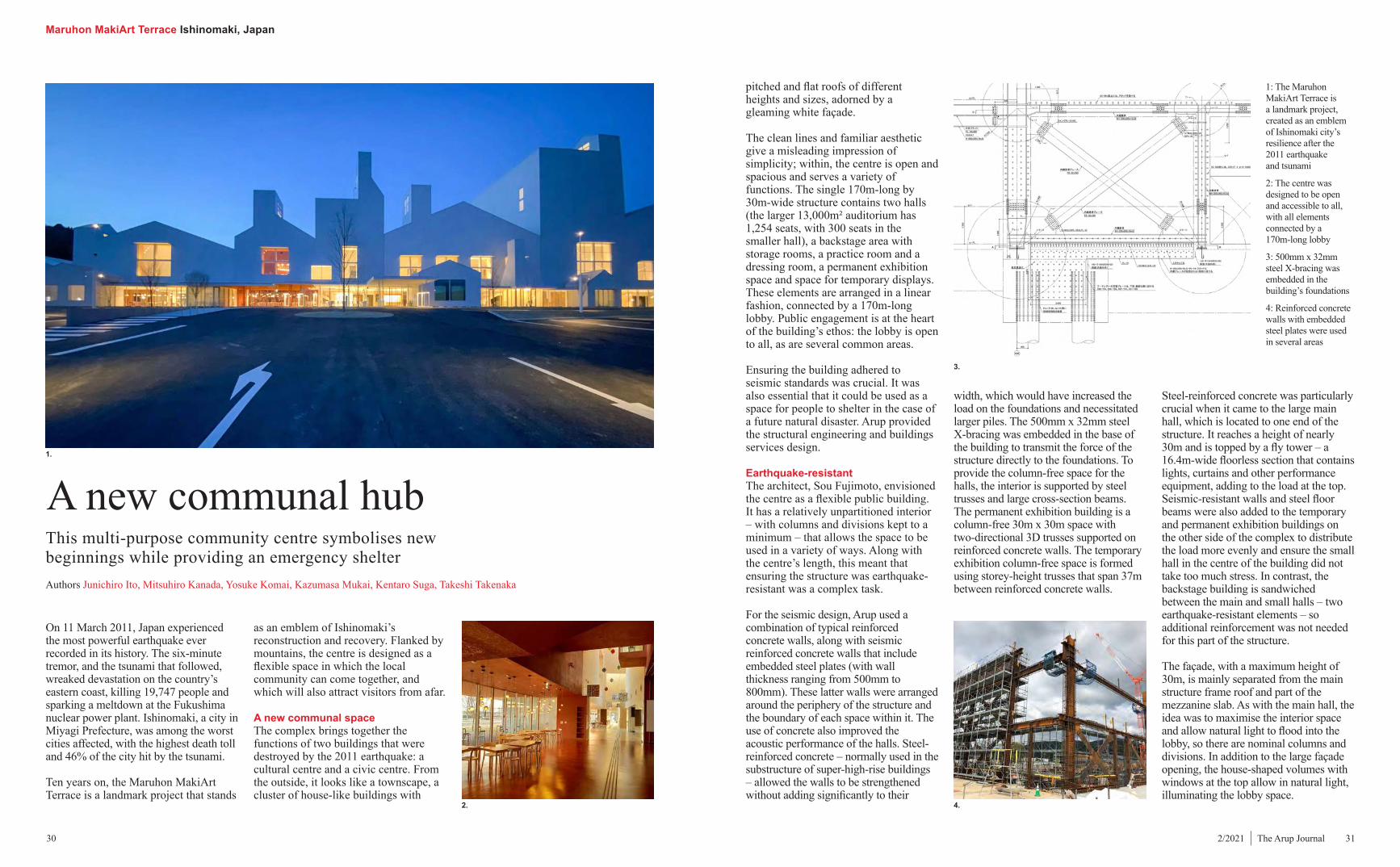
1: The Maruhon MakiArt Terrace is a landmark project, created as an emblem of Ishinomaki city’s resilience after the 2011 earthquake and tsunami
2: The centre was designed to be open and accessible to all, with all elements connected by a 170m-long lobby
3: 500mm x 32mm steel X-bracing was embedded in the building’s foundations
4: Reinforced concrete walls with embedded steel plates were used in several areas
as an emblem of Ishinomaki’s reconstruction and recovery. Flanked by mountains, the centre is designed as a flexible space in which the local community can come together, and which will also attract visitors from afar.
A new communal spaceThe complex brings together the functions of two buildings that were destroyed by the 2011 earthquake: a cultural centre and a civic centre. From the outside, it looks like a townscape, a cluster of house-like buildings with
pitched and flat roofs of different heights and sizes, adorned by a gleaming white façade.
The clean lines and familiar aesthetic give a misleading impression of simplicity; within, the centre is open and spacious and serves a variety of functions. The single 170m-long by 30m-wide structure contains two halls (the larger 13,000m² auditorium has 1,254 seats, with 300 seats in the smaller hall), a backstage area with storage rooms, a practice room and a dressing room, a permanent exhibition space and space for temporary displays. These elements are arranged in a linear fashion, connected by a 170m-long lobby. Public engagement is at the heart of the building’s ethos: the lobby is open to all, as are several common areas.
Ensuring the building adhered to seismic standards was crucial. It was also essential that it could be used as a space for people to shelter in the case of a future natural disaster. Arup provided the structural engineering and buildings services design.
Earthquake-resistantThe architect, Sou Fujimoto, envisioned the centre as a flexible public building. It has a relatively unpartitioned interior – with columns and divisions kept to a minimum – that allows the space to be used in a variety of ways. Along with the centre’s length, this meant that ensuring the structure was earthquake-resistant was a complex task.
For the seismic design, Arup used a combination of typical reinforced concrete walls, along with seismic reinforced concrete walls that include embedded steel plates (with wall thickness ranging from 500mm to 800mm). These latter walls were arranged around the periphery of the structure and the boundary of each space within it. The use of concrete also improved the acoustic performance of the halls. Steel-reinforced concrete – normally used in the substructure of super-high-rise buildings – allowed the walls to be strengthened without adding significantly to their
width, which would have increased the load on the foundations and necessitated larger piles. The 500mm x 32mm steel X-bracing was embedded in the base of the building to transmit the force of the structure directly to the foundations. To provide the column-free space for the halls, the interior is supported by steel trusses and large cross-section beams. The permanent exhibition building is a column-free 30m x 30m space with two-directional 3D trusses supported on reinforced concrete walls. The temporary exhibition column-free space is formed using storey-height trusses that span 37m between reinforced concrete walls.
Steel-reinforced concrete was particularly crucial when it came to the large main hall, which is located to one end of the structure. It reaches a height of nearly 30m and is topped by a fly tower – a 16.4m-wide floorless section that contains lights, curtains and other performance equipment, adding to the load at the top. Seismic-resistant walls and steel floor beams were also added to the temporary and permanent exhibition buildings on the other side of the complex to distribute the load more evenly and ensure the small hall in the centre of the building did not take too much stress. In contrast, the backstage building is sandwiched between the main and small halls – two earthquake-resistant elements – so additional reinforcement was not needed for this part of the structure.
The façade, with a maximum height of 30m, is mainly separated from the main structure frame roof and part of the mezzanine slab. As with the main hall, the idea was to maximise the interior space and allow natural light to flood into the lobby, so there are nominal columns and divisions. In addition to the large façade opening, the house-shaped volumes with windows at the top allow in natural light, illuminating the lobby space.
2. 4.

Maruhon MakiArt Terrace Ishinomaki, Japan
return and hot water was set at 45°C with a 36°C return.
Chemical filters and steam humidifiers were installed in the exhibition and storage rooms to strictly control temperature, humidity and air quality, as delicate objects are kept in these areas. For the comfort of the audience, the main hall is cooled and heated via an air supply system and return duct at the back and bottom of each seat respectively. This allows airflow to be tightly controlled to service only occupied areas. Arup worked closely with the architect to adjust the shapes of the seat backs for optimum airflow. A coil bypassing system was installed to dehumidify the stage.
To ensure the best possible acoustic experience for theatregoers, the machine room and air handling units were located on the rooftop away from the main halls, and appropriate sound attenuators were installed in the ducts. A dedicated transformer was provided
systems so they would not be visible as part of the triangular roof design. The humid climate poses a challenge in minimising energy use because the major source of cooling/heating load is from the ventilation system. Chilled water temperature is normally set as 7°C for dehumidification, and hot water is required even during the summer for reheating purposes. Parametric analysis was carried out to establish the optimum chilled and hot water temperature, for greater efficiency of the chillers and heatpumps. The chilled water was set at 10°C with a 19°C
performance for the foundations. Typically, the piles take axial load only. However, under large seismic load some of the piles will take a greater tensile reaction, with the tensile pile capacity directly affecting the seismic performance of the building. To verify the capacity, a 50m-long tensile pile capacity test was conducted on site.
Heating, ventilation, cooling and soundVarious types of air-conditioning systems were installed to meet the needs of the centre’s different spaces. Arup used Revit to design these
32 332/2021 | The Arup Journal
5.
7.
8.
6.
To ensure strength and rigidity, the façade is made up of a steel-plated concrete slab. A large canopy on the lower part of the façade provides horizontal support, while bracing and hat trusses tie the system together. In order to prevent the building façade from deforming out of plane, a pin at the centre of the façade connects the main structure with bracing along the façade’s mullions. Steel pin joints are typically circular, but Arup designed a new type of oval pin – circular on two ends but with the sides cut off – as this was more cost-effective to manufacture, while still having the 200mm length that Japanese building codes require. In addition, a square slot hole and bolt were developed for seismic force transmission. Government approval was needed for this novel solution.
The slender columns of the façade have varying axial forces in different locations. In order to unify the column size, hinge columns were introduced. Hinges were installed 700mm above the base of each column to reduce the buckling length of the column; this enabled the use of slender 90mm columns throughout.
Typically, for a building of this length, an expansion joint would be included in the structure to manage the expansion
and contraction of the building frame due to thermal load and to prevent damage to the structure. With this movement largely due to the roof structure being exposed to direct sunlight, Arup analysed the unusual roof form and determined that its uneven surface would absorb enough of the expansion and contraction caused by the temperature load to remain within allowable tolerance (5mm).
Concrete crack control was an important requirement, as the building contains no expansion joints and has continuous fair-faced concrete surfaces. Three types of concrete shrinkage tests were carried out to determine the most appropriate concrete mix. Limestone concrete provided the best performance in terms of shrinkage and was used for all concrete elements above the foundations.
The foundationsTo minimise cost, it was necessary to reduce the number of piles used in the foundations as far as possible. The structure’s large eaves provided a solution: they were used to transmit the load horizontally, with bracing placed along the façade’s mullions, limiting the number of columns and piles to one every 30m.
The rock head level of the Maruhon MakiArt Terrace site was assumed to be sloped according to site inspection and, although it was initially thought that the piles’ length could be adjusted on site by penetrating into rock, the soil conditions did not allow this method. To address the problem, Arup designed 2m-long prefabricated piles, which were pre-bored and inserted, with the protruding pile heads cut on site. This method did not require root penetration and could be used with the uneven rock head level conditions. It also brought cost savings and, along with the structure’s earthquake-resistant walls and steel trusses, meant that the number of columns could be reduced from the originally planned 160 to 120.
The pile tensile capacity was a critical issue in achieving the required seismic
10: To ensure the best acoustics in the theatre, sound attenuators were installed in the ducts, and the machine room and air handling units were located far away
8: Using Revit, Arup designed the building services systems so they would not be visible from ground level
9: The seats in the main hall each have their own air supply system
5: To reduce the columns’ buckling length, hinges were installed within each column
6: A 50m-long tensile pile capacity test was conducted on site
7: BIM was used for the complex building services
10.
9.
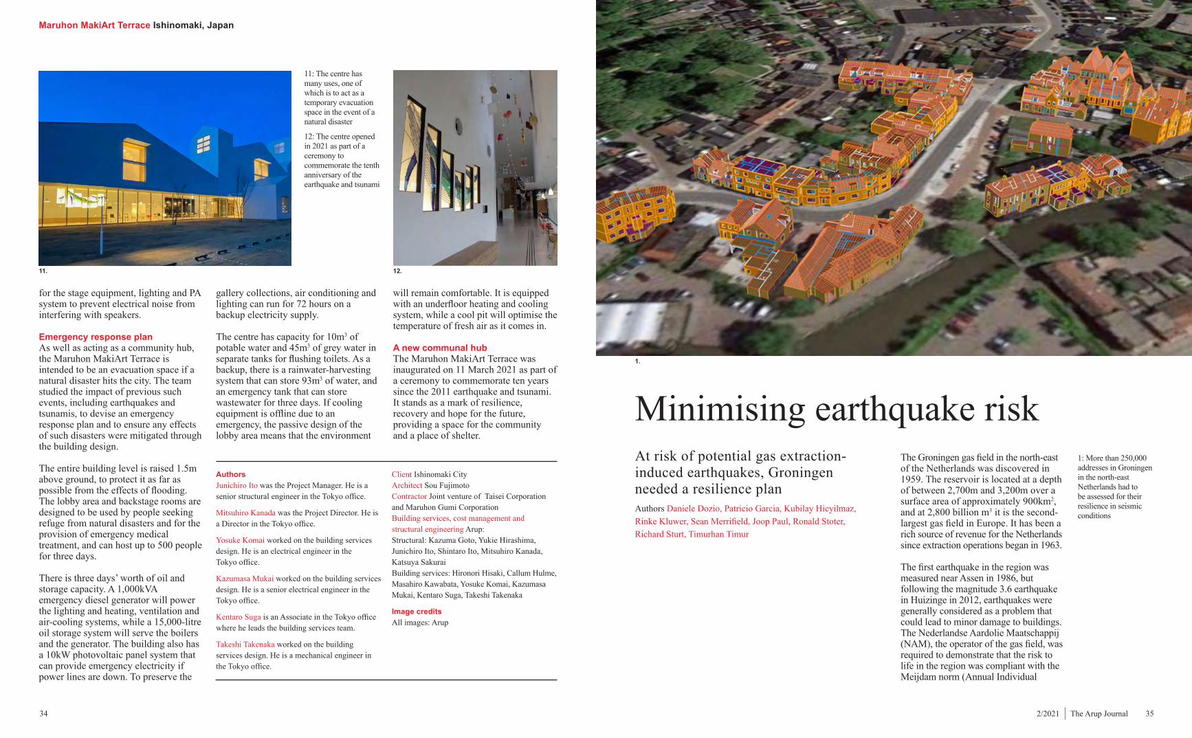
Maruhon MakiArt Terrace Ishinomaki, Japan
34 352/2021 | The Arup Journal
gallery collections, air conditioning and lighting can run for 72 hours on a backup electricity supply.
The centre has capacity for 10m3 of potable water and 45m3 of grey water in separate tanks for flushing toilets. As a backup, there is a rainwater-harvesting system that can store 93m3 of water, and an emergency tank that can store wastewater for three days. If cooling equipment is offline due to an emergency, the passive design of the lobby area means that the environment
will remain comfortable. It is equipped with an underfloor heating and cooling system, while a cool pit will optimise the temperature of fresh air as it comes in.
A new communal hubThe Maruhon MakiArt Terrace was inaugurated on 11 March 2021 as part of a ceremony to commemorate ten years since the 2011 earthquake and tsunami. It stands as a mark of resilience, recovery and hope for the future, providing a space for the community and a place of shelter.
for the stage equipment, lighting and PA system to prevent electrical noise from interfering with speakers.
Emergency response planAs well as acting as a community hub, the Maruhon MakiArt Terrace is intended to be an evacuation space if a natural disaster hits the city. The team studied the impact of previous such events, including earthquakes and tsunamis, to devise an emergency response plan and to ensure any effects of such disasters were mitigated through the building design.
The entire building level is raised 1.5m above ground, to protect it as far as possible from the effects of flooding. The lobby area and backstage rooms are designed to be used by people seeking refuge from natural disasters and for the provision of emergency medical treatment, and can host up to 500 people for three days.
There is three days’ worth of oil and storage capacity. A 1,000kVA emergency diesel generator will power the lighting and heating, ventilation and air-cooling systems, while a 15,000-litre oil storage system will serve the boilers and the generator. The building also has a 10kW photovoltaic panel system that can provide emergency electricity if power lines are down. To preserve the
AuthorsJunichiro Ito was the Project Manager. He is a senior structural engineer in the Tokyo office.
Mitsuhiro Kanada was the Project Director. He is a Director in the Tokyo office.
Yosuke Komai worked on the building services design. He is an electrical engineer in the Tokyo office.
Kazumasa Mukai worked on the building services design. He is a senior electrical engineer in the Tokyo office.
Kentaro Suga is an Associate in the Tokyo office where he leads the building services team.
Takeshi Takenaka worked on the building services design. He is a mechanical engineer in the Tokyo office.
Client Ishinomaki CityArchitect Sou FujimotoContractor Joint venture of Taisei Corporation and Maruhon Gumi Corporation Building services, cost management and structural engineering Arup: Structural: Kazuma Goto, Yukie Hirashima, Junichiro Ito, Shintaro Ito, Mitsuhiro Kanada, Katsuya Sakurai Building services: Hironori Hisaki, Callum Hulme, Masahiro Kawabata, Yosuke Komai, Kazumasa Mukai, Kentaro Suga, Takeshi Takenaka
Image creditsAll images: Arup
11. 12.
11: The centre has many uses, one of which is to act as a temporary evacuation space in the event of a natural disaster
12: The centre opened in 2021 as part of a ceremony to commemorate the tenth anniversary of the earthquake and tsunami
1: More than 250,000 addresses in Groningen in the north-east Netherlands had to be assessed for their resilience in seismic conditions
At risk of potential gas extraction-induced earthquakes, Groningen needed a resilience planAuthors Daniele Dozio, Patricio Garcia, Kubilay Hicyilmaz, Rinke Kluwer, Sean Merrifield, Joop Paul, Ronald Stoter, Richard Sturt, Timurhan Timur
Minimising earthquake riskThe Groningen gas field in the north-east of the Netherlands was discovered in 1959. The reservoir is located at a depth of between 2,700m and 3,200m over a surface area of approximately 900km2, and at 2,800 billion m3 it is the second-largest gas field in Europe. It has been a rich source of revenue for the Netherlands since extraction operations began in 1963.
The first earthquake in the region was measured near Assen in 1986, but following the magnitude 3.6 earthquake in Huizinge in 2012, earthquakes were generally considered as a problem that could lead to minor damage to buildings. The Nederlandse Aardolie Maatschappij (NAM), the operator of the gas field, was required to demonstrate that the risk to life in the region was compliant with the Meijdam norm (Annual Individual
1.
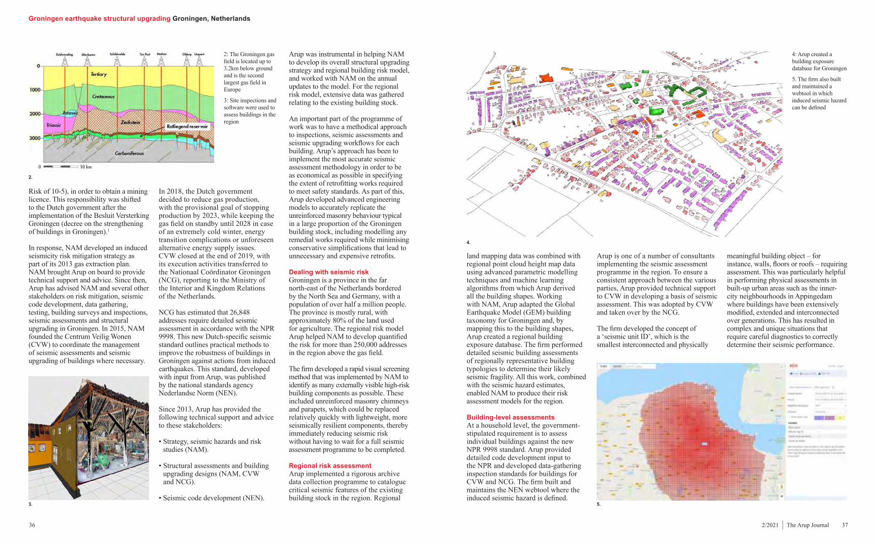
Groningen earthquake structural upgrading Groningen, Netherlands
36 372/2021 | The Arup Journal
Arup is one of a number of consultants implementing the seismic assessment programme in the region. To ensure a consistent approach between the various parties, Arup provided technical support to CVW in developing a basis of seismic assessment. This was adopted by CVW and taken over by the NCG.
The firm developed the concept of a ‘seismic unit ID’, which is the smallest interconnected and physically
Risk of 10-5), in order to obtain a mining licence. This responsibility was shifted to the Dutch government after the implementation of the Besluit Versterking Groningen (decree on the strengthening of buildings in Groningen).1
In response, NAM developed an induced seismicity risk mitigation strategy as part of its 2013 gas extraction plan. NAM brought Arup on board to provide technical support and advice. Since then, Arup has advised NAM and several other stakeholders on risk mitigation, seismic code development, data gathering, testing, building surveys and inspections, seismic assessments and structural upgrading in Groningen. In 2015, NAM founded the Centrum Veilig Wonen (CVW) to coordinate the management of seismic assessments and seismic upgrading of buildings where necessary.
In 2018, the Dutch government decided to reduce gas production, with the provisional goal of stopping production by 2023, while keeping the gas field on standby until 2028 in case of an extremely cold winter, energy transition complications or unforeseen alternative energy supply issues. CVW closed at the end of 2019, with its execution activities transferred to the Nationaal Coördinator Groningen (NCG), reporting to the Ministry of the Interior and Kingdom Relations of the Netherlands.
NCG has estimated that 26,848 addresses require detailed seismic assessment in accordance with the NPR 9998. This new Dutch-specific seismic standard outlines practical methods to improve the robustness of buildings in Groningen against actions from induced earthquakes. This standard, developed with input from Arup, was published by the national standards agency Nederlandse Norm (NEN).
Since 2013, Arup has provided the following technical support and advice to these stakeholders:
• Strategy, seismic hazards and risk studies (NAM).
• Structural assessments and building upgrading designs (NAM, CVW and NCG).
• Seismic code development (NEN).
land mapping data was combined with regional point cloud height map data using advanced parametric modelling techniques and machine learning algorithms from which Arup derived all the building shapes. Working with NAM, Arup adapted the Global Earthquake Model (GEM) building taxonomy for Groningen and, by mapping this to the building shapes, Arup created a regional building exposure database. The firm performed detailed seismic building assessments of regionally representative building typologies to determine their likely seismic fragility. All this work, combined with the seismic hazard estimates, enabled NAM to produce their risk assessment models for the region.
Building-level assessmentsAt a household level, the government-stipulated requirement is to assess individual buildings against the new NPR 9998 standard. Arup provided detailed code development input to the NPR and developed data-gathering inspection standards for buildings for CVW and NCG. The firm built and maintains the NEN webtool where the induced seismic hazard is defined.
2: The Groningen gas field is located up to 3.2km below ground and is the second largest gas field in Europe
3: Site inspections and software were used to assess buildings in the region
Arup was instrumental in helping NAM to develop its overall structural upgrading strategy and regional building risk model, and worked with NAM on the annual updates to the model. For the regional risk model, extensive data was gathered relating to the existing building stock.
An important part of the programme of work was to have a methodical approach to inspections, seismic assessments and seismic upgrading workflows for each building. Arup’s approach has been to implement the most accurate seismic assessment methodology in order to be as economical as possible in specifying the extent of retrofitting works required to meet safety standards. As part of this, Arup developed advanced engineering models to accurately replicate the unreinforced masonry behaviour typical in a large proportion of the Groningen building stock, including modelling any remedial works required while minimising conservative simplifications that lead to unnecessary and expensive retrofits.
Dealing with seismic riskGroningen is a province in the far north-east of the Netherlands bordered by the North Sea and Germany, with a population of over half a million people. The province is mostly rural, with approximately 80% of the land used for agriculture. The regional risk model Arup helped NAM to develop quantified the risk for more than 250,000 addresses in the region above the gas field.
The firm developed a rapid visual screening method that was implemented by NAM to identify as many externally visible high-risk building components as possible. These included unreinforced masonry chimneys and parapets, which could be replaced relatively quickly with lightweight, more seismically resilient components, thereby immediately reducing seismic risk without having to wait for a full seismic assessment programme to be completed.
Regional risk assessmentArup implemented a rigorous archive data collection programme to catalogue critical seismic features of the existing building stock in the region. Regional
2.
3.
4.
5.
meaningful building object – for instance, walls, floors or roofs – requiring assessment. This was particularly helpful in performing physical assessments in built-up urban areas such as the inner-city neighbourhoods in Appingedam where buildings have been extensively modified, extended and interconnected over generations. This has resulted in complex and unique situations that require careful diagnostics to correctly determine their seismic performance.
4: Arup created a building exposure database for Groningen
5. The firm also built and maintained a webtool in which induced seismic hazard can be defined

Groningen earthquake structural upgrading Groningen, Netherlands
38 392/2021 | The Arup Journal
simulations were fed back into the analysis software, input data and modelling methods. Arup performed extensive cross-validation of the material models developed for LS-DYNA to assess masonry buildings in Groningen against the country-specific test data. The experiments provided insights on how and how far unreinforced masonry houses, while not originally designed to resist seismic loading, can nevertheless withstand earthquakes before collapsing.
ModellingA range of assessment methods were employed for different buildings. In general, the simpler code-based methods, while quick to apply, were shown to give far more conservative results,3 leading to recommendations for more intrusive and potentially unnecessary retrofit measures. The mechanisms by which seismic actions may be resisted by such buildings are not always obvious and are often not allowed for in simpler assessment methods, resulting in conservative simplifications and far-reaching assumptions.
In contrast, the non-linear time history (NLTH) analysis method, in which detailed finite element models are subjected to earthquake shaking motion time-histories, determines more accurately how a structure will resist seismic loads without imposing over-conservative assumptions or incorrectly ignoring critical behaviours. The NLTH method allows strengthening measures to be focused where they are truly needed, reducing disruption to building owners and occupiers. Arup has continuously worked to improve the NLTH methodology in order to cost-effectively assess larger and more complex buildings. The methodology is able to identify buildings that meet the
the Netherlands, Arup executed a large-scale research programme. This helped determine the engineering parameters for the building materials used in the region and calibrated the numerical simulation models used to determine the capacity of buildings against physical test data.2 The extensive laboratory testing campaign comprised around 25 wall specimens loaded cyclically, seven shake table experiments on full-scale masonry house specimens, and numerous experiments on material samples and other small specimens. The extensive array of data helped to increase the accuracy of the assessment models.
As-built construction data for the existing building stock was sourced from municipality archives and further information was obtained from the public register of buildings. Rapid visual surveys were supplemented by an inspection programme where buildings were visited, assessment-specific photos taken, 360° scans performed, measurements made and – in specific locations – opening up works carried out to validate the form of construction, obtain structural member dimensions and confirm the presence or absence of construction features.
specified safety standards, eliminating disruptive and costly seismic retrofit works that simply cannot be done by other methods.
NLTH analyses were carried out using the finite element software LS-DYNA. The program has strong capabilities for modelling components of buildings, soils, soil-structure interaction and construction sequencing. However, at the start of the project, the software was lacking a practical way to model the complex behaviour of unreinforced masonry – the only available method was to model each brick separately. Arup developed a custom material model for LS-DYNA to capture the strength and failure modes of unreinforced masonry under dynamic loads.
The material model can capture cracking directions, the ‘interlock’ between bricks in adjacent courses, and the degradation of strength and stiffness under cyclic deformation without needing to model individual bricks and mortar. This enabled fast solution times while retaining the required accuracy and the ability to include other relevant components of the building in the model.
Lessons learned from comparing the laboratory test results against
For each assessed building, an initial building information model (BIM) was developed using archive drawings and site inspection data to create advanced engineering analysis models to determine if remedial measures were required. All remedial works are quantified, costed and reported to the NCG.
Existing building stock Understanding the mix of existing building typologies, their components and materials used in construction is crucial to modelling the buildings’ behaviour under seismic loads and to plan any required seismic remedial works. Arup implemented an extensive data collection programme from the field and the laboratory. Working for NAM, in collaboration with EUCENTRE in Italy, LNEC in Portugal, Delft University of Technology and Eindhoven University of Technology in
6: Arup developed a repetitive Cairo pentagon pattern for the layout and plan shape of the pots
9: Structural support is provided by the struts within the petals, the cast-in-place ‘star beams’ and edge beams
10.
7.
9.
8.
9–10: Arup’s custom material model for LS-DYNA captures the strength and failure modes of unreinforced masonry under dynamic loads
6: Arup developed the concept of a ‘seismic unit ID’, which was applied to the smallest building objects that needed assessment
7: A full-scale shake table test was carried out as part of the assessments
8: LS-DYNA software was used to predict responses to different kinds of ground motion
6.

Groningen earthquake structural upgrading Groningen, Netherlands
40 412/2021 | The Arup Journal
practice and client preferences. In the process of selecting the preferred strengthening measures, the main drivers considered were:
• Minimising the disturbance for residents by reducing as much as possible any intrusive work in living spaces. For example, using a thin fibre-reinforced cementitious matrix system (which does not add significant weight to a structure) instead of concrete thickening to increase the capacity of the masonry walls.
• Selecting materials typically used in small residential buildings rather than more industrialised systems. This enabled remediation works to
be as simple as possible and provided benefits to the local economy; for example, the use of locally sourced timber over steel where feasible.
• Cost-effectiveness.
A hierarchical system of the building components (foundations, walls, floors and roofs) was established so that strengthening measures could be applied to each of these components and to the interfaces between different components. By defining components and strengthening measures with simple codes, combinations of details could easily be created for assessed buildings.
Having a clear system to identify the retrofit details was a key element in incorporating them in the assessment workflows, ensuring high levels of consistency between the building assessments being carried out by many Arup teams. For each assessed building, the firm determined the bill of quantities of the identified seismic retrofits; from this, cost plans were generated.
Digital elementsArup’s multidisciplinary teams are delivering a significant proportion
of inspections, advanced analysis and engineering retrofit designs for buildings in the region. Project delivery teams are generating a large volume of information that has to be exchanged across disciplines in order to coordinate the work. Arup developed a workflow that revolved around a centralised data warehouse. It acts as a single source of truth from which all teams can find the latest information on every building in the region that Arup is assessing. This maximises consistency across the many project teams and streamlines processes.
The project workflow starts with a digital building inspection process, where a 3D structural model of a building is prepared from 3D laser scans that are collected on site and supplemented with floor plans from archive drawings. Every element in the BIM is tagged, using a consistent naming convention. The data from the physical inspections is used to confirm assumed tags or complete missing tags in the 3D model. All 3D models are reviewed by those who carried out the inspection, and, where Arup was the inspection party, by the analyst as well as the design manager for each assessment, thereby ensuring quality and consistency.
The NLTH models included all significant structural elements such as floor and roof timbers, which are joined to one another using connection elements that have pre-defined strength, stiffness, ductility and seating lengths. Where timber elements bear on the masonry over a limited contact length, the ability of the timber to fall off the wall was included in the model. In some cases, the building’s foundations and a block of soil were included in the model so that local rocking modes, differential settlement and sliding of the building relative to the ground were all modelled. The LS-DYNA models were used to predict the as-built response to specified ground motion demands and were sufficiently detailed to enable modelling of different strengthening measures where required.
Retrofit detailsAchieving consistency in the structural strengthening measures required was a considerable challenge. Creating a collection of details readily available for use that could be quickly incorporated in the workflows became a priority.
Arup combined its international expertise with detailed local knowledge. A team of engineers developed suitable strengthening measures, in terms of best local and international
13.
Once the inspection geometry is fully tagged and reviewed, the model is uploaded to the data warehouse for handover to the analysis teams. The 3D models are then enriched for the as-built seismic assessment analysis before retrofitting measures are implemented where required.
Fast and accurate The data-focused workflow has improved the quality and consistency of the assessments, allowing more detailed and accurate models to be developed. These models give a better understanding of the building behaviour under earthquake loading.
The advanced simulation models minimise the structural upgrading works needed by being able to model the buildings accurately without having to incorporate conservative assumptions necessary in the simpler methods. Using the specified seismic hazard levels, the detailed data-driven NLTH approach has made it possible to show that a number of the existing buildings meet the NPR 9998 safety standard without the need for strengthening works.
The project workflow has been improved across a number of critical
13: All building elements are tagged in the BIM program using a consistent naming convention
parts, including the model set-up (building geometry, material properties, soil layering and properties), model run time, structural upgrading measures and automation of the reports produced for each building assessment.
The improvements have resulted in building assessment times being reduced from months to weeks, making the NLTH method commercially competitive for complex buildings compared with other simpler assessment methods. The methods used on this project also have other applications. The data-driven workflow is accurate and can be applied to simulate and assess many types of loads. Complex and historically valuable masonry and stone buildings are able to be seismically assessed for code compliance identifying the least intrusive strengthening measures. The large-scale data-driven workflow can be used to help assess and maintain regional or national engineering assets, be they buildings, roads, bridges, quay walls or similar, assisting local and national authorities to make the most of their existing assets.
OutcomesArup’s rigorous data collection has contributed towards identifying vulnerable addresses across the region.
Bestaand dakbeschot
Bestaande nokgording
Nieuwe houten klos
.Houten klossen
Nieuwe multiplex platen 2x9mm
Schroef
Bestaande gording
200m lang koudgewalst staal
Nieuw multiplex platen 18mm
(Existing roof plywood)
(Existing ridge beam)
(New blocking element)
(Additional blocking)@1200mm
(New plywood 2x9mm)
(Screw)
(Existing purlin)
(200mm long cold formed steelplate @600mm)
(New plywood 18mm)
Do not scale
A4
Name
© Arup
Scale at A4
P500: Constructieve principedetails
Date
(Typical Structural Details)
1 : 10
(R1₂-R1₂)₈
Verbinding in de nok
Gordingendak hout(Gable to Gable timber roof)
(Connection at ridge) P500
: Typ
isch
e C
onst
ruct
ieve
Det
ails
-(T
ypic
al S
truct
ural
Det
ails
)
19/03/20 Rev 1.0
11.
12.
11–12: The collection of building details helped to achieve consistency in the structural strengthening measures
Section AA
Bestaand multiplex dak
Bestaande dakspoor
Nieuw multiplex 2x9mm
Nieuwe houten regel
Nieuw multiplex 12mm
Schroef
Nieuwe houten regel
Nieuwe houten klos
Nieuw multiplex 2x9mm
Bestaand dakbeschot
Gespijkerde verbinding
Nieuwe houten klos
Nieuw multiplex 2x9mm
Spouwankers
Nieuw multiplex 18mm
Sok-anker
Gezettestaalplaat
Schroef
Knieschot
Nieuw multiplex 2x9mm
Staalprofiel
Opvulspecie
Spouwmuur
Nieuw multiplex12mm(New Plywood12mm)
Nieuwe Houten klos(New blocking
element)
Bestaande gording
Bestaande gording
(Existing roof planking)
Existing rafter
(New Plywood 2x9mm)
(New timber plate)
(New Plywood 12mm)
(Screw)
(New timber plate)
(New blocking element)
(New Plywood 2x9mm)
(Existing roof planking)
(Nail connection)
(New blocking element)
(New Plywood 2x9mm)
(Wall ties)
(New Plywood 18mm)
(Sock anchor)
(Steelbent plate)
(Screw)
(Knee wall)
(New Plywood 2x9mm)
(Steel angle)
(Rectifying grout)
(Masonry cavity wall)
(Existing purlin)
(Existing purlin)
Do not scale
A4
Name
© Arup
Scale at A4
P500: Constructieve principedetails
Date
(W2₁-R1₁-S5₁)₄,₇21/10/20
Wall-roof-floor connection with knee wall and steel angle +sock anchor
P500
: T
ypis
ch
e C
on
str
uctieve
Deta
ils -
(Typic
al S
tru
ctu
ral D
eta
ils)
Draft
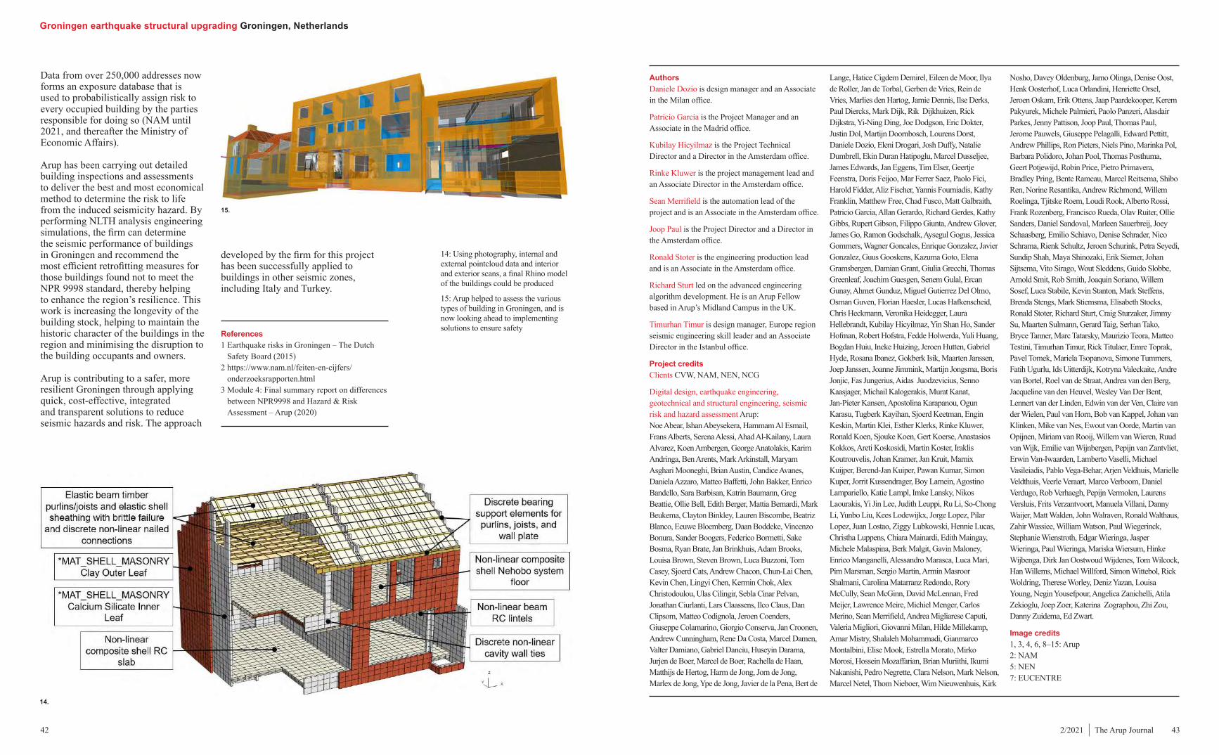
Groningen earthquake structural upgrading Groningen, Netherlands
42 432/2021 | The Arup Journal
14: Using photography, internal and external pointcloud data and interior and exterior scans, a final Rhino model of the buildings could be produced
15: Arup helped to assess the various types of building in Groningen, and is now looking ahead to implementing solutions to ensure safety
Authors Daniele Dozio is design manager and an Associate in the Milan office.
Patricio Garcia is the Project Manager and an Associate in the Madrid office.
Kubilay Hicyilmaz is the Project Technical Director and a Director in the Amsterdam office.
Rinke Kluwer is the project management lead and an Associate Director in the Amsterdam office.
Sean Merrifield is the automation lead of the project and is an Associate in the Amsterdam office.
Joop Paul is the Project Director and a Director in the Amsterdam office.
Ronald Stoter is the engineering production lead and is an Associate in the Amsterdam office.
Richard Sturt led on the advanced engineering algorithm development. He is an Arup Fellow based in Arup’s Midland Campus in the UK.
Timurhan Timur is design manager, Europe region seismic engineering skill leader and an Associate Director in the Istanbul office.
Project creditsClients CVW, NAM, NEN, NCG
Digital design, earthquake engineering, geotechnical and structural engineering, seismic risk and hazard assessment Arup:Noe Abear, Ishan Abeysekera, Hammam Al Esmail, Frans Alberts, Serena Alessi, Ahad Al-Kailany, Laura Alvarez, Koen Ambergen, George Anatolakis, Karim Andringa, Ben Arents, Mark Arkinstall, Maryam Asghari Mooneghi, Brian Austin, Candice Avanes, Daniela Azzaro, Matteo Baffetti, John Bakker, Enrico Bandello, Sara Barbisan, Katrin Baumann, Greg Beattie, Ollie Bell, Edith Berger, Mattia Bernardi, Mark Beukema, Clayton Binkley, Lauren Biscombe, Beatriz Blanco, Eeuwe Bloemberg, Daan Boddeke, Vincenzo Bonura, Sander Boogers, Federico Bormetti, Sake Bosma, Ryan Brate, Jan Brinkhuis, Adam Brooks, Louisa Brown, Steven Brown, Luca Buzzoni, Tom Casey, Sjoerd Cats, Andrew Chacon, Chun-Lai Chen, Kevin Chen, Lingyi Chen, Kermin Chok, Alex Christodoulou, Ulas Cilingir, Sebla Cinar Pelvan, Jonathan Ciurlanti, Lars Claassens, Ilco Claus, Dan Clipsom, Matteo Codignola, Jeroen Coenders, Giuseppe Colamarino, Giorgio Conserva, Jan Croonen, Andrew Cunningham, Rene Da Costa, Marcel Damen, Valter Damiano, Gabriel Danciu, Huseyin Darama, Jurjen de Boer, Marcel de Boer, Rachella de Haan, Matthijs de Hertog, Harm de Jong, Jorn de Jong, Marlex de Jong, Ype de Jong, Javier de la Pena, Bert de
Lange, Hatice Cigdem Demirel, Eileen de Moor, Ilya de Roller, Jan de Torbal, Gerben de Vries, Rein de Vries, Marlies den Hartog, Jamie Dennis, Ilse Derks, Paul Diercks, Mark Dijk, Rik Dijkhuizen, Rick Dijkstra, Yi-Ning Ding, Joe Dodgson, Eric Dokter, Justin Dol, Martijn Doornbosch, Lourens Dorst, Daniele Dozio, Eleni Drogari, Josh Duffy, Natalie Dumbrell, Ekin Duran Hatipoglu, Marcel Dusseljee, James Edwards, Jan Eggens, Tim Elser, Geertje Feenstra, Doris Feijoo, Mar Ferrer Saez, Paolo Fici, Harold Fidder, Aliz Fischer, Yannis Fourniadis, Kathy Franklin, Matthew Free, Chad Fusco, Matt Galbraith, Patricio Garcia, Allan Gerardo, Richard Gerdes, Kathy Gibbs, Rupert Gibson, Filippo Giunta, Andrew Glover, James Go, Ramon Godschalk, Aysegul Gogus, Jessica Gommers, Wagner Goncales, Enrique Gonzalez, Javier Gonzalez, Guus Gooskens, Kazuma Goto, Elena Gramsbergen, Damian Grant, Giulia Grecchi, Thomas Greenleaf, Joachim Guesgen, Senem Gulal, Ercan Gunay, Ahmet Gunduz, Miguel Gutierrez Del Olmo, Osman Guven, Florian Haesler, Lucas Hafkenscheid, Chris Heckmann, Veronika Heidegger, Laura Hellebrandt, Kubilay Hicyilmaz, Yin Shan Ho, Sander Hofman, Robert Hofstra, Fedde Holwerda, Yuli Huang, Bogdan Huiu, Ineke Huizing, Jeroen Hutten, Gabriel Hyde, Rosana Ibanez, Gokberk Isik, Maarten Janssen, Joep Janssen, Joanne Jimmink, Martijn Jongsma, Boris Jonjic, Fas Jungerius, Aidas Juodzevicius, Senno Kaasjager, Michail Kalogerakis, Murat Kanat, Jan-Pieter Kansen, Apostolina Karapanou, Ogun Karasu, Tugberk Kayihan, Sjoerd Keetman, Engin Keskin, Martin Klei, Esther Klerks, Rinke Kluwer, Ronald Koen, Sjouke Koen, Gert Koerse, Anastasios Kokkos, Areti Koskosidi, Martin Koster, Iraklis Koutrouvelis, Johan Kramer, Jan Kruit, Marnix Kuijper, Berend-Jan Kuiper, Pawan Kumar, Simon Kuper, Jorrit Kussendrager, Boy Lamein, Agostino Lampariello, Katie Lampl, Imke Lansky, Nikos Laourakis, Yi Jin Lee, Judith Leuppi, Ru Li, So-Chong Li, Yunbo Liu, Kees Lodewijkx, Jorge Lopez, Pilar Lopez, Juan Lostao, Ziggy Lubkowski, Hennie Lucas, Christha Luppens, Chiara Mainardi, Edith Maingay, Michele Malaspina, Berk Malgit, Gavin Maloney, Enrico Manganelli, Alessandro Marasca, Luca Mari, Pim Marsman, Sergio Martin, Armin Masroor Shalmani, Carolina Matarranz Redondo, Rory McCully, Sean McGinn, David McLennan, Fred Meijer, Lawrence Meire, Michiel Menger, Carlos Merino, Sean Merrifield, Andrea Migliarese Caputi, Valeria Migliori, Giovanni Milan, Hilde Millekamp, Amar Mistry, Shalaleh Mohammadi, Gianmarco Montalbini, Elise Mook, Estrella Morato, Mirko Morosi, Hossein Mozaffarian, Brian Muriithi, Ikumi Nakanishi, Pedro Negrette, Clara Nelson, Mark Nelson, Marcel Netel, Thom Nieboer, Wim Nieuwenhuis, Kirk
Nosho, Davey Oldenburg, Jarno Olinga, Denise Oost, Henk Oosterhof, Luca Orlandini, Henriette Orsel, Jeroen Oskam, Erik Ottens, Jaap Paardekooper, Kerem Pakyurek, Michele Palmieri, Paolo Panzeri, Alasdair Parkes, Jenny Pattison, Joop Paul, Thomas Paul, Jerome Pauwels, Giuseppe Pelagalli, Edward Pettitt, Andrew Phillips, Ron Pieters, Niels Pino, Marinka Pol, Barbara Polidoro, Johan Pool, Thomas Posthuma, Geert Potjewijd, Robin Price, Pietro Primavera, Bradley Pring, Bente Rameau, Marcel Reitsema, Shibo Ren, Norine Resantika, Andrew Richmond, Willem Roelinga, Tjitske Roem, Loudi Rook, Alberto Rossi, Frank Rozenberg, Francisco Rueda, Olav Ruiter, Ollie Sanders, Daniel Sandoval, Marleen Sauerbreij, Joey Schaasberg, Emilio Schiavo, Denise Schrader, Nico Schrama, Rienk Schultz, Jeroen Schurink, Petra Seyedi, Sundip Shah, Maya Shinozaki, Erik Siemer, Johan Sijtsema, Vito Sirago, Wout Sleddens, Guido Slobbe, Arnold Smit, Rob Smith, Joaquin Soriano, Willem Sosef, Luca Stabile, Kevin Stanton, Mark Steffens, Brenda Stengs, Mark Stiemsma, Elisabeth Stocks, Ronald Stoter, Richard Sturt, Craig Sturzaker, Jimmy Su, Maarten Sulmann, Gerard Taig, Serhan Tako, Bryce Tanner, Marc Tatarsky, Maurizio Teora, Matteo Testini, Timurhan Timur, Rick Titulaer, Emre Toprak, Pavel Tomek, Mariela Tsopanova, Simone Tummers, Fatih Ugurlu, Ids Uitterdijk, Kotryna Valeckaite, Andre van Bortel, Roel van de Straat, Andrea van den Berg, Jacqueline van den Heuvel, Wesley Van Der Bent, Lennert van der Linden, Edwin van der Ven, Claire van der Wielen, Paul van Horn, Bob van Kappel, Johan van Klinken, Mike van Nes, Ewout van Oorde, Martin van Opijnen, Miriam van Rooij, Willem van Wieren, Ruud van Wijk, Emilie van Wijnbergen, Pepijn van Zantvliet, Erwin Van-Iwaarden, Lamberto Vaselli, Michael Vasileiadis, Pablo Vega-Behar, Arjen Veldhuis, Marielle Veldthuis, Veerle Veraart, Marco Verboom, Daniel Verdugo, Rob Verhaegh, Pepijn Vermolen, Laurens Versluis, Frits Verzantvoort, Manuela Villani, Danny Waijer, Matt Walden, John Walraven, Ronald Walthaus, Zahir Wassiee, William Watson, Paul Wiegerinck, Stephanie Wienstroth, Edgar Wieringa, Jasper Wieringa, Paul Wieringa, Mariska Wiersum, Hinke Wijbenga, Dirk Jan Oostwoud Wijdenes, Tom Wilcock, Han Willems, Michael Willford, Simon Wittebol, Rick Woldring, Therese Worley, Deniz Yazan, Louisa Young, Negin Yousefpour, Angelica Zanichelli, Atila Zekioglu, Joep Zoer, Katerina Zographou, Zhi Zou, Danny Zuidema, Ed Zwart.
Image credits 1, 3, 4, 6, 8–15: Arup 2: NAM 5: NEN 7: EUCENTRE
14.
15.
Data from over 250,000 addresses now forms an exposure database that is used to probabilistically assign risk to every occupied building by the parties responsible for doing so (NAM until 2021, and thereafter the Ministry of Economic Affairs).
Arup has been carrying out detailed building inspections and assessments to deliver the best and most economical method to determine the risk to life from the induced seismicity hazard. By performing NLTH analysis engineering simulations, the firm can determine the seismic performance of buildings in Groningen and recommend the most efficient retrofitting measures for those buildings found not to meet the NPR 9998 standard, thereby helping to enhance the region’s resilience. This work is increasing the longevity of the building stock, helping to maintain the historic character of the buildings in the region and minimising the disruption to the building occupants and owners.
Arup is contributing to a safer, more resilient Groningen through applying quick, cost-effective, integrated and transparent solutions to reduce seismic hazards and risk. The approach
developed by the firm for this project has been successfully applied to buildings in other seismic zones, including Italy and Turkey.
References 1 Earthquake risks in Groningen – The Dutch
Safety Board (2015)2 https://www.nam.nl/feiten-en-cijfers/
onderzoeksrapporten.html3 Module 4: Final summary report on differences
between NPR9998 and Hazard & Risk Assessment – Arup (2020)

Macquarie University Ainsworth Building Sydney, Australia
44 452/2021 | The Arup Journal
1: Sustainability was at the heart of the construction of the four-storey timber Ainsworth Building
2: The adoption of an almost entirely mass-timber structure above ground level significantly reduced the embodied carbon in the building
Macquarie University’s Ainsworth Building is the flagship building of the university’s Medicine and Health Sciences Faculty. The completion of the new four-storey timber-engineered structure has deepened the links between learning, training, research and medical practice on the campus. The 3,325m2 facility provides students and staff with a dynamic and flexible place to work and study, and houses multiple state-of-the-art lecture theatres and team-based learning spaces. Arup’s team, comprising more than 15 disciplines, worked alongside architecture and design practice Architectus to ensure sustainability was at the heart of the development and to realise the ambitious rapid construction programme. Following the tender stage, Arup’s civil, structural and acoustic teams were novated to Buildcorp, the design and build contractor, with the firm also carrying out a peer review role on the building services design for Macquarie University. The construction on a constrained site on the Macquarie University campus in Sydney took just over a year, with the building opening in July 2020.
Taking multi-storey timber structures to the next level A new home for medicine and health sciences training in an innovative and sustainable timber-engineered buildingAuthors Mike King, Kengo Takamatsu, Enrico Zara
1.
2.

Macquarie University Ainsworth Building Sydney, Australia
46 472/2021 | The Arup Journal
W-shaped Victorian ash hardwood 550mm x 550mm glulam columns frame the entrance to the building. They are an important feature supporting the cantilevered floor on the south side of the building and the column-free façade above level 1. The W form, along with a timber-clad steel box transfer beam at level 1, enables unobstructed views from inside and out and creates a spacious, welcoming foyer. This element also supplemented the lateral stability provided by the CLT core. The expansive level 1 entrance foyer showcases the detail of the engineered timber flooring system, welcoming people as they enter
The adoption of an almost entirely mass-timber structure above ground level had multiple benefits. The structure has low embodied carbon; it was able to be fabricated off site to a high degree of accuracy; construction was quick and efficient; and the construction methods used were far quieter than those adopted for non-timber structures, meaning construction did not disturb the adjacent sensitive buildings, including Macquarie University Hospital. Levels 0, 1 and 2 were designed by Arup with an integrated building services fit-out, while level 3 was designed as core and shell with services capacity sized based on the typical floor level. The plant room is located within a lightweight steel frame structure at roof level.
The high-performance building envelope has a glazed façade that allows maximum light into the narrow site, creating a visible link from learning spaces to the hospital and allowing passers-by to look in at the learning in action – all reaffirming the vital connection between education and health. Responding to its surroundings, the new facility connects
of assembly. Importantly, they ensured that the final pre-cut European spruce pieces from Austria were of a length that could be readily transported to the site in Sydney. For the beam and column connections, a notched column design was used, with the beam typically bearing 150mm on the notched column, rather than connecting to the column face. This improved construction time – taking less than 20 minutes for each installation – and lessened the shear load, allowing a reduction in connection and timber member size. Arup explored using a precast concrete core but moved away from that proposal due to the site constraints and heavier loads created by a concrete core, which would have necessitated larger foundations and more cranage. Instead, the 140mm-deep CLT floors and CLT walls were used for lateral stability, using the 180mm-thick and 240mm-thick CLT cores in the centre of the building and the 180mm-thick north-east shear wall.
Achieving the vision for this multi-storey timber structure and enabling a rapid construction programme required a high level of multidisciplinary collaboration, coordination and detailed design from the start of the project. One of the main challenges was correlating construction of the timber structure with installation of the building services and the acoustic and fire engineering requirements. Precise multidisciplinary coordination was also essential for the penetrations in the glulam beams. Where possible, services were reduced or grouped together to minimise the reduction in strength and stiffness of the structure where they ran through the engineered notches in the beams. The ends of the beams were notched at the perimeter just below the slab to enable the services to run close to the soffit of the floor above, with the services distributed to the interior of the floor plate by running parallel to the glulam beams.
The thermal, fire and acoustic performance requirements were simultaneously considered to optimise safety and acoustic qualities without detracting from the architectural intent.
To showcase the internal timber surfaces and maintain the floor plate’s open aesthetic, Arup’s design enclosed the building services within the structure. With the ceiling installed, the services are concealed, giving a clean soffit with only the timber beams and ceiling visible to building occupants. Working within a BIM environment, the firm produced a detailed model that was imported by the contractor into the fabrication software, allowing the timber to be factory pre-cut for swift assembly on site and thereby minimising the construction impact on Macquarie’s campus environment.
bringing in Architectus and Arup to design the Ainsworth Building utilising a similar engineered timber construction, but this time for a multi-storey development. The new development is in keeping with the campus masterplan, which emphasises sustainable buildings, cutting-edge facilities and industry collaboration.
Multi-storey timber constructionThe building integrates three types of engineered timber: glulam European spruce for the internal columns and beams; CLT European spruce for the internal floors, lift core and shear walls; and glulam Victorian ash hardwood for the external columns. The structural frame was formed from a 2.4m x 15m grid of glulam columns (800mm x 350mm) and beams (1,380mm x 350mm). The glazing mullions were aligned with the columns at 2.4m centres, helping to minimise the depth of the edge beams and enabling the double-glazed glass façade to draw optimal daylight into the interior spaces.
The connections were designed for strength, durability, appearance and ease
pedestrians from Innovation Road to the campus’s main walkway, Wally’s Walk, via landscaped paths.
MasterplanArup supported Architectus in developing Macquarie University’s Central Courtyard Precinct Masterplan in 2015. Since then, the two firms have had the opportunity to influence the campus further by working together on the design of the Central Courtyard and the Incubator Building – an award-winning addition to the Macquarie Park Innovation District, which is home to more than 180 large international companies and 200 small businesses.
The single-storey Incubator structure was formed using a cross-laminated timber (CLT) roof supported on large-span glued laminated timber (glulam) beams and V columns, with the design allowing for prefabrication of many components. This made construction more cost-efficient and quicker – the building was completed in just five months.
Macquarie University looked to build on the success of the Incubator by
4.
5.
5: The W-shaped glulam columns frame the building entrance and support the cantilevered floor on the south side and the column-free faҫade above level 1
6: Installation of the building services and the acoustic and fire engineering requirements required detailed coordination with the timber structure
4
22
2
PE
Level 0368800
CD R/A Riser S/A Riser
VAV unit
Cable Tray Dry Fire Cables S/A Duct Sprinkler Pipe
S/A Connection Plenum
05
C
0403
D
2
ARP-CS-6101
3
ARP-CS-6101
S/A Riser
R/A Riser
R/A Grille
VAV unit
S/A Diffuser
VCD
S/A duct
VCD
Sprinkler Head
Lighting Fixture
Dry Fire Cables
Speaker
Cable Tray
Sprinkler PipeSmoke Detector
R/A Intake
Level 0368800
Level 0368800
C
D
DNotch in timber beam
Cable TrayDry Fire Cables
Sprinkler Pipe
R/A via gap at the top of fascia panel
SA Duct
Ceiling
0
A1
Do not scale
A B C D E F G H I J K L M
1
2
3
4
5
6
7
8
9
10
Client Project Title
© Arup
Scale at A1
Suitability
Name
Arup Job No
Role
Rev
Drawing Title
NORTH
0 0 0 0 0mm
Architect
architectusLevel 18 MLC Centre19 Martin PlaceSydney NSW 2000Tel +61 (02) 8252 8400
TM
Date By Chkd AppdDate By Chkd AppdDate By Chkd AppdRev Rev Rev
As indicated
Clinical Education BuildingMacquarie University
Level 5, Barrack Place, 151 Clarence StreetSydney NSW 2000ph : 02 9320 9320fax : 02 9320 9321 258830
Bay Detail (Sheet 1 of 3)
For Tender
Combined Services
ARP-CS-6101
1For Tender1 19/11/18 AM JC EZ
1 : 25
Level 01 & 02 Bay Section A2
1 : 25
Level 01 & 02 - Bay Detail 11
1 : 25
Level 01 & 02 Bay Section B3
6.
3.
3: A notched column design was used for the beam and column connections
4: The structural frame is formed of glulam columns and beams

Macquarie University Ainsworth Building Sydney, Australia
48 492/2021 | The Arup Journal
The high-performance building envelope maximises views and natural light, reducing the need for artificial lighting during the day, with daylight sensors on the LED lighting system helping to conserve energy when there is sufficient natural light. The façade incorporates automated blinds (which have a manual override) that provide solar protection and glare control and are also connected to the building’s audio-visual systems. The blinds allow for high levels of thermal comfort to be maintained close to the glazed façade. The extra-large faҫade module of 2.4m x 4.5m allowed a very high thermal performance to be achieved by reducing losses due to thermal bridging in the frame.
A low-temperature variable air volume system maximises free cooling and modulates temperature according to building occupancy, while the natural and mixed-mode ventilation designed for the informal spaces at the entrances on levels 0 and 1 provides a natural connection to the outdoor environment. This gradual transition into the air-conditioned spaces allows the university to relax the temperature control, which is better for occupant wellbeing and energy efficiency. The natural ventilation louvres at the bottom and the top of the atrium are used at night to purge any heat built up in the building mass during the day. Greenhouse gas emissions are further curbed via a 28kW photovoltaic system located on the roof. Based on typical consumption and weather data, it is estimated that 10% to
W frame supports the 2.2m cantilevered floor section and the column-free façade above level 1. Structural window mullions were used on this façade to link the cantilevered floors and avoid excessive movement in this area.
Quiet constructionThe building location is a heavily constrained wedge-shaped piece of land that was previously used as an at-grade car park in an area between the university hospital and an existing faculty building. The speed of construction and quietness of the mass timber solution adopted meant that the university was able to fully utilise a piece of land that it would not have been viable to build on with more conventional construction materials and systems.
The use of timber enabled construction to take place as close as 10m from the external wall of the vibration-sensitive functions in the adjacent hospital, such as operating theatres, radiology rooms and intensive care units. Using prefabricated timber construction methods markedly reduced vibration, noise and dust from the construction site. The lightweight timber system also reduced foundation loads, further curtailing the noise and vibration impact on surrounding buildings by minimising the excavation work needed for foundations. Reinforced
concrete bored piles were used, rather than driven piles, to lessen the impact on the adjoining properties.
Sustainability focusThe building reflects the sustainability goals outlined in Macquarie University’s campus masterplan. From the project’s outset, Arup’s design team worked closely with Architectus to embed sustainability in the design and to develop strategies to improve energy efficiency. With an approximate 700 tonnes of timber structure, the building will save the carbon emission equivalent of five to six years of energy consumption during operation. The high-efficiency building services will reduce energy consumption and running costs for Macquarie University further.
third-party certified for sustainability by PEFC. The imported timber was shipped to a warehouse in Sydney and brought to site in a sequential manner. The timber structure had 1,341 individual pieces which were separately coded for tracking to site in 54 shipping containers, with the elements loaded into the containers to match the order of installation. It took three months to erect all the timber elements on campus, with Buildcorp managing an average 30-minute installation time for each element.
Sound and vibrationAlthough CLT has the benefit of a smaller mass compared with steel and concrete, it provides limited airborne and impact sound insulation and limited reverberation control. Therefore, as the Ainsworth Building is an active and collaborative space, Arup’s acoustic specialists were engaged from an early stage. The SoundLab in Arup’s Sydney office was used to demonstrate design options, enabling input from the university and architect to feed into the design. The multi-level solution reduced impact sound from footfall by using the floor buildup and space between beams in the ceiling cavity to carefully layer plasterboard and insulation materials. The fire and acoustic performance layers were optimised to maintain the minimum size of notches for services.
The floor buildup is carpet tile/timber flooring on acoustic packing, 40mm screed and 140mm CLT structure. Two layers of 13mm-thick plasterboard were fixed to the underside of the CLT and rockwool insulation placed above the ceiling. Vibration isolators were placed in the junctions between CLT walls and floor panels of the building’s core and teaching spaces to control flanking sound between the spaces. A perforated, visible ceiling surface was used to control reverberance and ensure clarity of speech and audio in the learning spaces. Arup carried out the floor vibration analysis using GSA software to ensure the floor response factor was kept within guidelines (the factor was below 8). Particular attention was paid to the area above the entrance where the
via the building’s elevated external walkway. The material, which is locally sourced Australian timber, was selected for its warm tonal qualities, its strength and its capacity to transfer vertical loads to the ground. This hardwood is also sympathetic to its surroundings of native eucalyptus woodland. A combination of solid and perforated birch plywood was used for wall panelling in theatres and learning spaces, with perforated blackbutt plywood used for the main entrance lobby ceiling. This helps to mediate reverberant noise and provides a fitting backdrop for the illuminated timber structure.
Local Australian glulam was incorporated wherever possible, reducing the energy consumed compared with materials transported internationally. Sourcing sustainable materials locally further reduced the embodied carbon costs of transport, supported local production and matched Macquarie University’s commitment to creating sustainable buildings and spaces. All CLT and glulam products imported from Austria were 100% Programme for the Endorsement of Forest Certification (PEFC) certified or made from wood that originates from PEFC-controlled sources. All Australian-sourced mass timber was
9: Vibration isolators were used to control flanking sound between spaces. They were placed between CLT walls and the floor panels in the building’s core and teaching spaces
10: The perforated ceiling controls reverberance and means that audio and speech in the learning spaces are clear
7: The site was a heavily constrained wedge-shaped piece of land between the university hospital and an existing faculty building
8: The 1,341 individual timber structure pieces were separately coded for tracking, with the elements loaded into the containers in order of installation
7.
8. 9.
10.

Macquarie University Ainsworth Building Sydney, Australia
50 512/2021 | The Arup Journal
the performance of the existing building’s systems.
CoordinationTo develop the four-storey timber design and ensure the rapid construction targets could be achieved, Arup’s multidisciplinary team worked in a BIM environment from the concept phase through to fit-out, integrating and coordinating the building services with the structural elements. All timber details, including connections, recesses, penetrations and notches, were developed and integrated into the model.
Prefabrication of the timber required precise up-front coordination and early detailed design of all the systems to enable overseas manufacture and facilitate a rapid onsite assembly, significantly curtailing the energy load during the construction period. This also reduced site waste and the number of vehicles required for construction.
Award-winningMacquarie University’s commitment to sustainability, innovation, and its staff and students saw Arup’s team work alongside Architectus to push design boundaries, creating an award-winning timber building. It won the People’s Choice Award at the 2020 Australian Timber Design Awards, and the Australian Institute of Architects 2021 NSW Architecture Award for Education. Following the success of the Central Courtyard Precinct, Incubator Building and the Ainsworth Building, Arup is continuing to work with the university, designing a new building for their Law Faculty that is due for completion in 2022.
AuthorsMike King was the Project Director. He is a Principal in the Sydney office.
Kengo Takamatsu led the structural design and was the Project Manager for the novated scope of the project. He is a senior engineer in the Sydney office.
Enrico Zara was the Project Manager, and led the design management for Arup’s multidisciplinary team on the project including the peer review of the building services design during construction. He is Arup’s key client contact for Macquarie University and is an Associate in the Sydney office.
Project creditsClient Macquarie UniversityArchitect ArchitectusContractor Buildcorp Timber fabricator BinderholzAudio-visual and multimedia, acoustics consulting, civil, structural, building services, faҫade and vibration engineering, sustainable buildings design Arup:Laura Badcock, Camilo Chalela, Jake Cherniayeff, Jethro Dickens, Richard Garland, Yu Goto, Jin Guo, Daniel Harris, Eve Hoskins, Dane Johns, Mike King, Henry Lam, Andrew Lawrence, Melvin Leong, Lulu Li, Stephen
Litsas, Elena Longo, Gavin Maloney, Adam Martin, Jason McKenzie, Chris Monk, James Murdoch, Bill Newton, Andrew Pettit, Livia Renhe, Nicky Shear, Kengo Takamatsu, James Trevorrow, Sihui Wang, Enrico Zara.
Image credits1, 3, 6, 10, 11: Arup2, 13: Architectus/Brett Boardman Photography4, 5, 7–9, 12: Victor Caringal/Arup
20% of the building’s energy needs will be provided by solar sources. The remaining energy is supplied by green power. Water-efficient fixtures were specified to minimise water use and the interior environment was improved through the selection of low volatile organic compound materials.
13.
11: Arup used BIM from concept phase to fit-out
12: Automated blinds, which can also be operated manually, provide solar protection and glare control
13: The Ainsworth Building opened in July 2020 and is a shining example of how timber can be used to create a sustainable building
11.
Rather than locating a new chiller plant room in the building, Arup refurbished the plant room in the adjacent 75 Talavera office building and connected the two systems together. This provided better efficiency for the Ainsworth Building and saved space in the plant room, while also improving
12.

The Arup Journal Vol.56 No.2 (2/2021) Editor: Macdara Ferris Designer: Wardour Email: [email protected]
Published by Arup 8 Fitzroy Street London W1T 4BJ, UK. Tel: +44 (0)20 7636 1531 All articles ©Arup 2021
www.arup.com
Printed by Geoff Neal Group Produced on FSC® paper and printed with vegetable- based inks.
1. Little Island, New York City, USA: Timothy Schenck; 2. Pearl Red Winery, Xingning, China: Zhangchao; 3. South East of Scotland Transport Partnership Strategic Network, UK: Math Roberts Photography; 4. Başakşehir Çam and Sakura City Hospital, Istanbul, Turkey: Rönesans Holding Engineering Group; 5. Maruhon MakiArt Terrace, Ishinomaki, Japan: Arup; 6. Groningen earthquake structural upgrading, Groningen, Netherlands: Arup; 7. Macquarie University Ainsworth Building, Sydney, Australia: Victor Caringal/Arup.
Front cover image: Little Island, New York City, USA: Timothy Schenck
1
3 4 5
76
2