issn 0976 – 6340 (print) issn 0976 – 6359 (online ) … analysis...yawal, dist. jalgaon – 425...
TRANSCRIPT

International Journal of Mechanical Engineering and Technology (IJMET), ISSN 0976 –
6340(Print), ISSN 0976 – 6359(Online) Volume 3, Issue 2, May-August (2012), © IAEME
783
VIBRATION ANALYSIS AND CONTROL OF PIEZOELECTRIC
SMART STRUCTURES BY FEEDBACK CONTROLLER ALONG-
WITH SPECTRA PLUS SOFTWARE
Kishor B. Waghulde
1*, Dr. Bimlesh Kumar
2,
1Research Scholar and Associate Professor,
J.T.Mahajan College of Engineering Faizpur
Tal. Yawal, Dist. Jalgaon – 425 524. (Maharashtra), India *Corresponding author E-mail: [email protected]
Mobile: 09423490910, Fax: 02585-248181 2Principal, J.T. Mahajan College of Engineering, Faizpur
Tal. Yawal, Dist. Jalgaon – 425 524. (Maharashtra), India
E-mail: [email protected]
ABSTRACT
The locations of actuators and sensors over a structure determine the effectiveness of the
controller in controlling vibrations. If we need to control a particular vibration mode, we have
to place actuators and sensors in locations with high control. In many cases of vibration
control, low frequency modes are considered to be important. Hence, we only need to
consider a certain number of modes in the placement of actuators and sensors. We extended
the methodology for finding optimal placement of general actuators and sensors over a
flexible structure. For vibration analysis ANSYS software is used. Experimentation is done
for control vibration and to find optimal position of piezoelectric actuator/sensor over a thin
plate. To obtain frequency response from PZT actuators and sensors, Spectra plus software is
used.
Key words: Vibration Analysis, Actuators and Sensors, Feedback controller Optimal
Placement, Finite Element Method, Spectra plus software.
INTRODUCTION
Active vibration control in distributed structures is of practical interest because of the
demanding requirement for guaranteed performance. This is particularly important in light-
weight structures as they generally have low internal damping. An active vibration control
system requires sensors, actuators, and a controller. The design process of such a system
encompasses three main phases such as structural design, optimal placement of sensors and
actuators and controller design. In vibration suppression of structures, locations of sensors
INTERNATIONAL JOURNAL OF MECHANICAL ENGINEERING AND TECHNOLOGY (IJMET)
ISSN 0976 – 6340 (Print)
ISSN 0976 – 6359 (Online)
Volume 3, Issue 2, May-August (2012), pp. 783-795
© IAEME: www.iaeme.com/ijmet.html
Journal Impact Factor (2012): 3.8071 (Calculated by GISI)
www.jifactor.com
IJMET
© I A E M E

International Journal of Mechanical Engineering and Technology
6340(Print), ISSN 0976 – 6359(Online) Volume 3, Issue 2, May
and actuators have a major influence on the performance of the control system. It is well
known that misplaced sensors and actuators lead to problems such as the lack of observability
or controllability. Active vibration c
a structure is reduced by applying counter force to the structure that is appropriately out of
phase but equal in force and amplitude to the original vibration. As a result two opposing
forces cancel each other, and structure essentially stops vibrating. Techniques like use of
springs, pads, dampers, etc have been used previously in order to control vibrations. These
techniques are known as ‘Passive Vibration Control Techniques’. They have limitatio
versatility and can control the frequencies only within a particular range of bandwidth. Hence
there is a requirement for ‘Active Vibration Control’. ‘Active Vibration Control’ makes use
of ‘Smart Structures’ [3,5]. This system requires sensors,
compensator that performs well when vibration occurs. Smart Structures are used in bridges,
trusses, buildings, mechanical systems, space vehicles, telescopes, and so on. The analysis of
a basic structure can help improve
conditions involving vibrations. “A Smart Structure” means a structure that can sense an
external disturbance and respond to that with active control in real time to maintain the
mission requirements. A Smart Structure typically consists of a host structure incorporated
with sensors and actuators coordinated by a controller. The integrated structured system is
called Smart Structure because it has the ability to perform self diagnosis and adapt to
environmental change. One promising application of such smart structure is the control and
suppression of unwanted structural vibrations. Fig
of the basic elements of a smart structure
Figure 1: Schematic Repre
Elements of a Smart Structure
Optimal Placement of Piezoelectric Actuators
Consider the placement of a single actuator, say the
a single input version of system
structural deflection. Each modal contribution depends on the location of the
the structure. Thus, if we intend to find the optimal placement for the actuator, the
International Journal of Mechanical Engineering and Technology (IJMET), ISSN 0976
6359(Online) Volume 3, Issue 2, May-August (2012), © IAEME
784
and actuators have a major influence on the performance of the control system. It is well
known that misplaced sensors and actuators lead to problems such as the lack of observability
or controllability. Active vibration control is defined as a technique in which the vibration of
a structure is reduced by applying counter force to the structure that is appropriately out of
phase but equal in force and amplitude to the original vibration. As a result two opposing
el each other, and structure essentially stops vibrating. Techniques like use of
springs, pads, dampers, etc have been used previously in order to control vibrations. These
techniques are known as ‘Passive Vibration Control Techniques’. They have limitatio
versatility and can control the frequencies only within a particular range of bandwidth. Hence
there is a requirement for ‘Active Vibration Control’. ‘Active Vibration Control’ makes use
. This system requires sensors, actuators, a source of power and a
compensator that performs well when vibration occurs. Smart Structures are used in bridges,
trusses, buildings, mechanical systems, space vehicles, telescopes, and so on. The analysis of
a basic structure can help improve the performance of the structures under poor working
conditions involving vibrations. “A Smart Structure” means a structure that can sense an
external disturbance and respond to that with active control in real time to maintain the
Smart Structure typically consists of a host structure incorporated
with sensors and actuators coordinated by a controller. The integrated structured system is
called Smart Structure because it has the ability to perform self diagnosis and adapt to
nmental change. One promising application of such smart structure is the control and
suppression of unwanted structural vibrations. Figure 1 depicts the schematic representation
of the basic elements of a smart structure [2,4].
Figure 1: Schematic Representation of the Basic
Elements of a Smart Structure
Piezoelectric Actuators
Consider the placement of a single actuator, say the jth
actuator. In this case, we consider only
a single input version of system G, i.e. the transfer function from jth
actuator signal to the
structural deflection. Each modal contribution depends on the location of the j
the structure. Thus, if we intend to find the optimal placement for the actuator, the
(IJMET), ISSN 0976 –
August (2012), © IAEME
and actuators have a major influence on the performance of the control system. It is well
known that misplaced sensors and actuators lead to problems such as the lack of observability
ontrol is defined as a technique in which the vibration of
a structure is reduced by applying counter force to the structure that is appropriately out of
phase but equal in force and amplitude to the original vibration. As a result two opposing
el each other, and structure essentially stops vibrating. Techniques like use of
springs, pads, dampers, etc have been used previously in order to control vibrations. These
techniques are known as ‘Passive Vibration Control Techniques’. They have limitations of
versatility and can control the frequencies only within a particular range of bandwidth. Hence
there is a requirement for ‘Active Vibration Control’. ‘Active Vibration Control’ makes use
actuators, a source of power and a
compensator that performs well when vibration occurs. Smart Structures are used in bridges,
trusses, buildings, mechanical systems, space vehicles, telescopes, and so on. The analysis of
the performance of the structures under poor working
conditions involving vibrations. “A Smart Structure” means a structure that can sense an
external disturbance and respond to that with active control in real time to maintain the
Smart Structure typically consists of a host structure incorporated
with sensors and actuators coordinated by a controller. The integrated structured system is
called Smart Structure because it has the ability to perform self diagnosis and adapt to
nmental change. One promising application of such smart structure is the control and
1 depicts the schematic representation
actuator. In this case, we consider only
actuator signal to the
jth
actuator on
the structure. Thus, if we intend to find the optimal placement for the actuator, the
International Journal of Mechanical Engineering and Technology (IJMET), ISSN 0976 –
6340(Print), ISSN 0976 – 6359(Online) Volume 3, Issue 2, May-August (2012), © IAEME
785
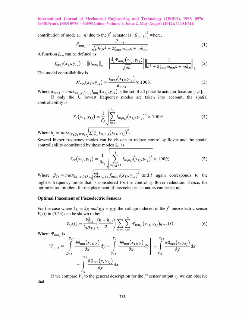
contribution of mode (m, n) due to the jth
actuator is ��������� where, ����� = ����ℎ �� + 2������� + ���� � 1� A function fmnj can be defined as: �������� , ���� = �������� = ��̅�Ψ������� , �����ℎ � 1�� + 2������� + ���� � 2� The modal controllability is !������, ���� = ��������, ����"��� × 100% 3� Where "��� = '(� )*,+*�∈-*�������� , ����is the set of all possible actuator location [1,5].
If only the Im lowest frequency modes are taken into account, the spatial
controllability is
./����, ���� = 10� 12��3�3�����, �����4567� × 100% 4�
Where 0� = '(� )*,+*�∈-*9∑ ��3�3�����, �����4567� . Several higher frequency modes can be chosen to reduce control spillover and the spatial
controllability contributed by these modes Sc2 is
./�����, ���� = 10��1 2 ��3�3����� , �����4̅6745<� × 100% 5�
Where 0�� = '(� )*,+*�∈-*9∑ ��3�3����� , �����4̅6745<� (>?@ ̅ again corresponds to the
highest frequency mode that is considered for the control spillover reduction. Hence, the
optimization problem for the placement of piezoelectric actuators can be set up.
Optimal Placement of Piezoelectric Sensors
For the case where k31 = k32 and g31 = g32, the voltage induced in the j
th piezoelectric sensor
Vsj(t) in (5.23) can be shown to be: AB� C� = DE���F�GE�� Hℎ + ℎI�2 J 2 2Ψ���∞
�7�∞
�7� ����, ����K�� C� 6� Where ��� is
Ψ��� = N O P∅������, ��P� ?� − O P∅������, ��P� ?�+ST+*T
+ST+*T U + O P∅����, ����P� ?�)ST
)3T− O P∅����, ����P� ?�)ST
)3T If we compare Vsj to the general description for the j
th sensor output vj, we can observe
that
International Journal of Mechanical Engineering and Technology (IJMET), ISSN 0976 –
6340(Print), ISSN 0976 – 6359(Online) Volume 3, Issue 2, May-August (2012), © IAEME
786
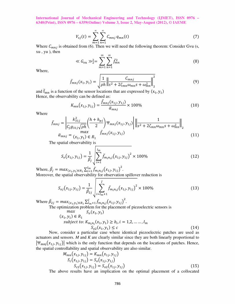
AB� C� = 2 2F���∞
�7�∞
�7� K�� C� 7� Where F��� is obtained from (6). Then we will need the following theorem: Consider Gvu (s,
xu , yu ), then ≪ �XY ≫��= 2 2��̅��[�7�
[�7� 8�
Where,
��̅�� ��, ��� = ] 1�ℎ F����� + 2������� + ���� �� 9�
and f̅̀ a is a function of the sensor locations that are expressed by x�, y�� Hence, the observability can be defined as: d������, ���� = ��̅�� ���, ����"e��� × 100% 10� Where ��̅�� = f DE���F�GE���ℎ Hℎ + ℎI�2 JΨ��� ��� , ����f 1�� + 2������� + ���� �
"e��� = '(� ��, ��� ∈ g���̅�� ��� , ���� 11� The spatial observability is
.h���� , ���� = 10̅� 12��̅3�3�����, �����4567� × 100% 12�
Where, 0̅� = '(� )*,+*�∈-* ∑ ��̅3�3����� , �����4567� . Moreover, the spatial observability for observation spillover reduction is
.h�����, ���� = 10̅��1 2 ��̅3�3�����, �����4̅6745<� × 100% 13�
Where 0̅�� = '(� )*,+*�∈-* ∑ ��̅3�3�����, �����4̅45<� . The optimization problem for the placement of piezoelectric sensors is '(� ��, ��� ∈ g�.h ��, ��� �ijklmCCn:d�3�3 ��, ��� ≥ j6, q = 1,2, …… , @� .h� ��, ��� ≤ m 14� Now, consider a particular case where identical piezoelectric patches are used as
actuators and sensors. M and K are clearly similar since they are both linearly proportional to tΨ`au���� , ����t which is the only function that depends on the locations of patches. Hence,
the spatial controllability and spatial observability are also similar. !������, ���� = d������, ���� ./����, ���� = .h����, ���� ./�����, ���� = .h�����, ���� 15� The above results have an implication on the optimal placement of a collocated
International Journal of Mechanical Engineering and Technology (IJMET), ISSN 0976 –
6340(Print), ISSN 0976 – 6359(Online) Volume 3, Issue 2, May-August (2012), © IAEME
787
piezoelectric actuator/sensor pair. Suppose we place a piezoelectric actuator on a structure
that gives certain levels of spatial controllability and modal controllability. Placing a
piezoelectric sensor at the same location would yield similar levels of spatial observability
and modal observability. Thus, we only need to optimize the placement of either actuator or
sensor. A similar optimization procedure can be used to find the optimal position and size of
each collocated actuator/sensor pair to obtain optimal spatial controllability, while
maintaining sufficient modal controllability levels [1,6,7,8].
Feedback Controller
There are two radically different approaches to disturbance rejection: feedback and feed-
forward. Although this text is entirely devoted to feedback control, it is important to point out
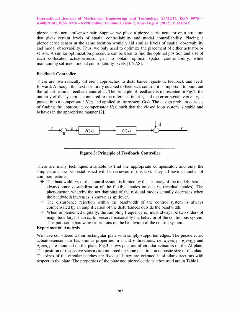
the salient features feedback controller. The principle of feedback is represented in Fig.2; the
output y of the system is compared to the reference input r, and the error signal, e = r - y, is
passed into a compensator H(s) and applied to the system G(s). The design problem consists
of finding the appropriate compensator H(s) such that the closed loop system is stable and
behaves in the appropriate manner [7].
Figure 2: Principle of Feedback Controller There are many techniques available to find the appropriate compensator, and only the
simplest and the best established will be reviewed in this text. They all have a number of
common features:
� The bandwidth ωc of the control system is limited by the accuracy of the model; there is
always some destabilization of the flexible modes outside ωc (residual modes). The
phenomenon whereby the net damping of the residual modes actually decreases when
the bandwidth increases is known as spillover.
� The disturbance rejection within the bandwidth of the control system is always
compensated by an amplification of the disturbances outside the bandwidth.
� When implemented digitally, the sampling frequency ωs must always be two orders of
magnitude larger than ωc to preserve reasonably the behavior of the continuous system.
This puts some hardware restrictions on the bandwidth of the control system.
Experimental Analysis
We have considered a thin rectangular plate with simply-supported edges. The piezoelectric
actuator/sensor pair has similar properties in x and y directions, i.e. k31=k32 , g31=g32 and
d31=d32 are mounted on the plate. Fig.3 shows position of circular actuators on the Al plate.
The position of respective sensors are mounted on same position on opposite size of the plate.
The sizes of the circular patches are fixed and they are oriented in similar directions with
respect to the plate. The properties of the plate and piezoelectric patches used are in Table1.
y d
r e H(s) G(s)

International Journal of Mechanical Engineering and Technology (IJMET), ISSN 0976 –
6340(Print), ISSN 0976 – 6359(Online) Volume 3, Issue 2, May-August (2012), © IAEME
788
Figure 3: Plate with Circular PZT Patches as Actuators
Table 1: Properties of the Piezoelectric Laminate Plate
Plate Young’s modulus, E
Plate Poisson’s ratio, ν
Plate density, ρh
:
:
:
7 x 10¹⁰
N/mm2
0.3
11.0kg/m2
Piezoceramic Young’s modulus, Ep
Piezoceramic Poisson’s ratio, νp
Charge constant, d31
Voltage constant, g31
Capacitance, C
Electromechanical coupling factor, k31
:
:
:
:
:
:
6.20 x 10¹⁰
N/mm2
0.3
-3.20 x 10⁻¹⁰
m/V
-9.50 x 10⁻³
Vm/N
4.50 x 10⁻⁷
F
0.44
The natural frequencies are found out by ANSYS and experimental method that are tabulated
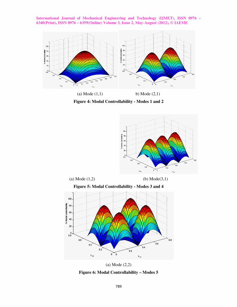
in Table 2. Figures 4 to 6 shows the modal controllability, Fig. 7 shows Spatial
Controllability and Fig. 8 shows Spatial Controllability of the first five modes versus the
piezoelectric actuator location. This location corresponds to placing the actuator in the middle
of the plate.
Table 2: First Six Modes of the Plate
No. Mode
(m,n)
Simulation �� (Hz)
Experiments �� (Hz)
Error
(%)
1
2
3
4
5
6
(1,1)
(2,1)
(1,2)
(3,1)
(2,2)
(3,2)
41.9
87.1
122.4
162.4
167.6
242.9
41.8
85.9
121.1
159.2
164.3
234.5
0.2
1.4
1.1
2.0
2.0
3.6
International Journal of Mechanical Engineering and Technology
6340(Print), ISSN 0976 – 6359(Online) Volume 3, Issue 2, May
(a) Mode (1,1) b) Mode (2,1)
Figure 4: Modal Controllability
(a) Mode (1,2) (b) Mode(3,1)
Figure 5: Modal Controllability
Figure 6:
International Journal of Mechanical Engineering and Technology (IJMET), ISSN 0976
6359(Online) Volume 3, Issue 2, May-August (2012), © IAEME
789
(a) Mode (1,1) b) Mode (2,1)
Figure 4: Modal Controllability - Modes 1 and 2
(a) Mode (1,2) (b) Mode(3,1)
Figure 5: Modal Controllability - Modes 3 and 4
(a) Mode (2,2)
Figure 6: Modal Controllability – Modes 5
(IJMET), ISSN 0976 –
August (2012), © IAEME
International Journal of Mechanical Engineering and Technology
6340(Print), ISSN 0976 – 6359(Online) Volume 3, Issue 2, May
Figure 7: Spatial Controllability
Figure 8: Spatial Controllability
Multi-waveform Signal Analyzer were used to obtain frequency responses from the
piezoelectric laminate patches. Important parameters of the plate, such as resonance
frequencies voltage variations, were obtained from
with Spectra plus software for the data acquisition and system control.
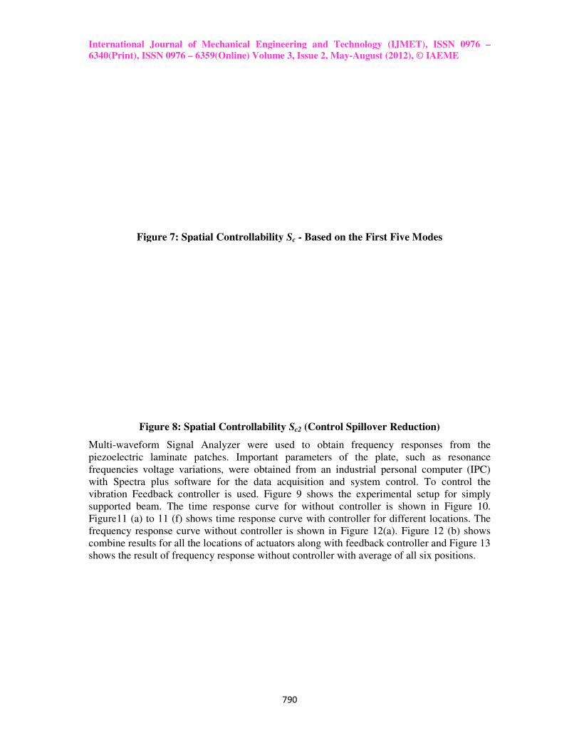
vibration Feedback controller is used. Figure 9 shows the experimental setup for simply
supported beam. The time response curve for without controller is shown in Fig
Figure11 (a) to 11 (f) shows time response curve
frequency response curve without controller is
combine results for all the locations of actuators alon
shows the result of frequency response without controller with average of all six positions.
International Journal of Mechanical Engineering and Technology (IJMET), ISSN 0976
6359(Online) Volume 3, Issue 2, May-August (2012), © IAEME
790
Figure 7: Spatial Controllability Sc - Based on the First Five Modes
Figure 8: Spatial Controllability Sc2 (Control Spillover Reduction)
Signal Analyzer were used to obtain frequency responses from the
patches. Important parameters of the plate, such as resonance
frequencies voltage variations, were obtained from an industrial personal computer (IPC)
for the data acquisition and system control. To control
vibration Feedback controller is used. Figure 9 shows the experimental setup for simply
supported beam. The time response curve for without controller is shown in Fig
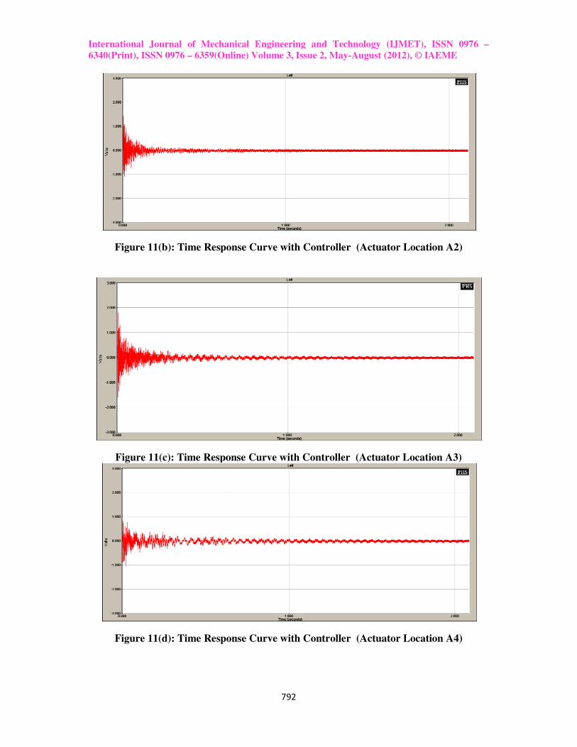
shows time response curve with controller for different locations
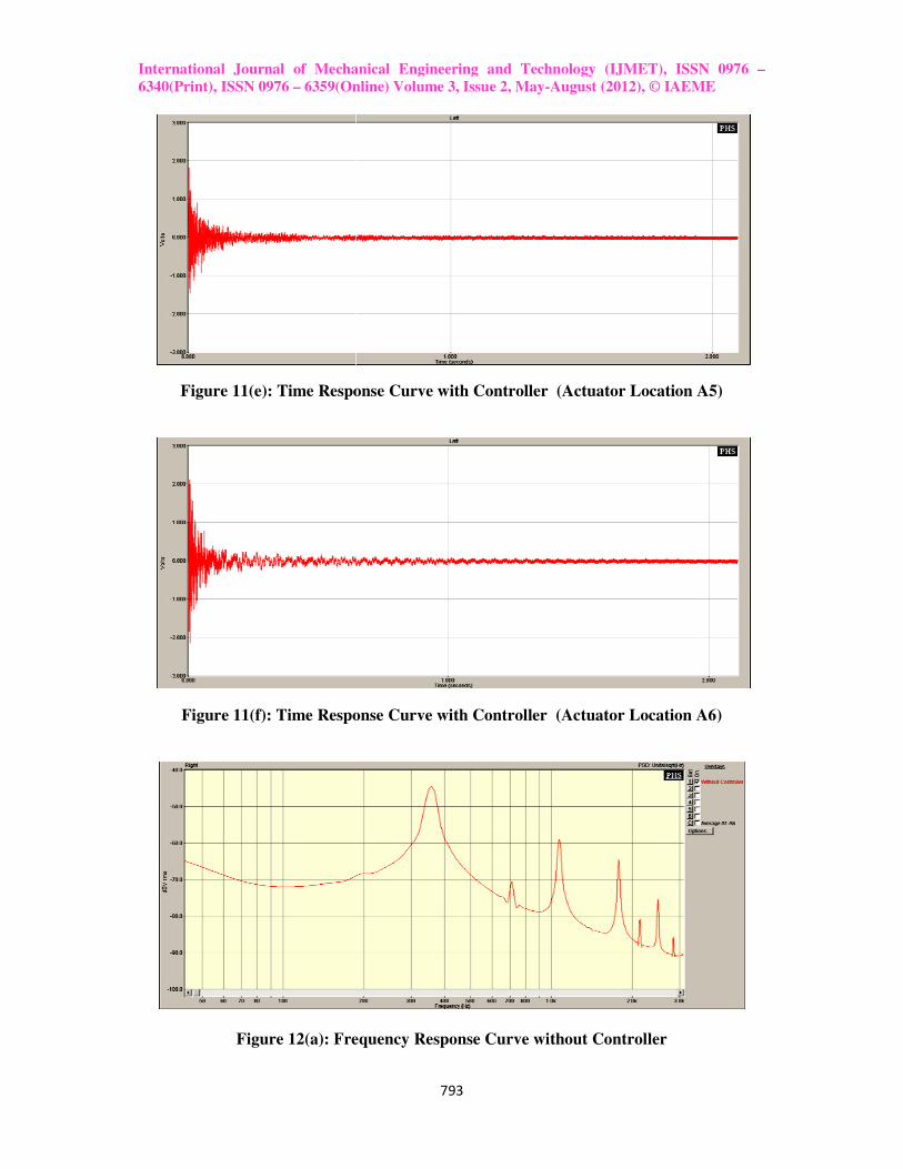
curve without controller is shown in Figure 12(a). Figure 12 (b) shows
combine results for all the locations of actuators along with feedback controller and F
shows the result of frequency response without controller with average of all six positions.
(IJMET), ISSN 0976 –
August (2012), © IAEME
Based on the First Five Modes
(Control Spillover Reduction)
Signal Analyzer were used to obtain frequency responses from the
patches. Important parameters of the plate, such as resonance
n industrial personal computer (IPC)
To control the
vibration Feedback controller is used. Figure 9 shows the experimental setup for simply
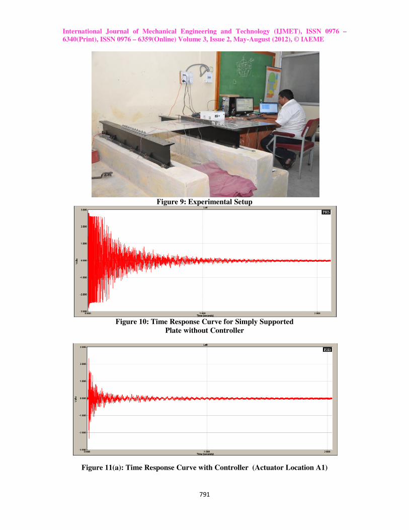
supported beam. The time response curve for without controller is shown in Figure 10.
t locations. The
. Figure 12 (b) shows
g with feedback controller and Figure 13
shows the result of frequency response without controller with average of all six positions.
International Journal of Mechanical Engineering and Technology
6340(Print), ISSN 0976 – 6359(Online) Volume 3, Issue 2, May
Figure 9:
Figure 10: Time Response C
Figure 11(a): Time Response C
International Journal of Mechanical Engineering and Technology (IJMET), ISSN 0976
6359(Online) Volume 3, Issue 2, May-August (2012), © IAEME
791
Figure 9: Experimental Setup
: Time Response Curve for Simply Supported
Plate without Controller
Time Response Curve with Controller (Actuator Location A1)
(IJMET), ISSN 0976 –
August (2012), © IAEME
Controller (Actuator Location A1)
International Journal of Mechanical Engineering and Technology
6340(Print), ISSN 0976 – 6359(Online) Volume 3, Issue 2, May
Figure 11(b): Time Response C
Figure 11(c): Time Response C
Figure 11(d): Time Response C
International Journal of Mechanical Engineering and Technology (IJMET), ISSN 0976
6359(Online) Volume 3, Issue 2, May-August (2012), © IAEME
792
Time Response Curve with Controller (Actuator Location A2)
Response Curve with Controller (Actuator Location A3)
Time Response Curve with Controller (Actuator Location A4)
(IJMET), ISSN 0976 –
August (2012), © IAEME
Location A2)
urve with Controller (Actuator Location A3)
Location A4)
International Journal of Mechanical Engineering and Technology
6340(Print), ISSN 0976 – 6359(Online) Volume 3, Issue 2, May
Figure 11(e): Time Response C
Figure 11(f): Time Response C
Figure 12(a): Frequency
International Journal of Mechanical Engineering and Technology (IJMET), ISSN 0976
6359(Online) Volume 3, Issue 2, May-August (2012), © IAEME
793
Time Response Curve with Controller (Actuator Location A5)
Time Response Curve with Controller (Actuator Location A6)
Frequency Response Curve without Controller
(IJMET), ISSN 0976 –
August (2012), © IAEME
urve with Controller (Actuator Location A5)
urve with Controller (Actuator Location A6)

International Journal of Mechanical Engineering and Technology
6340(Print), ISSN 0976 – 6359(Online) Volume 3, Issue 2, May
Figure 12(b): Frequency
Figure 12(b): Frequency
Due to the symmetry of the problem, the reading
locations that are parallel position along the width of the plate.
figures for pairs at locations A1 and A4, A2 and A5, A3and A6.
varying the actuator location along the length of the plate shows that the settling time has the
best values when the actuator is placed at locations A2 and A5. Also it can be seen that the
settling time value is better in the actuator locations A1 and A4 than locations A3 and
general, it can be said that placing the actuator middle of the plate gives better results than
placing it closer to the both ends
controlled by using feedback controller. Also in this c
A2and A5 than all other positions.
CONCLUSIONS
This paper presents the numerical analysis and experimental results of vibration suppression
of a simply supported plate bonded with circular PZT sensors and actuators. Fr
numerical studies we know that the spatial controllability and modal controllability were used
for optimal placement of collocated piezoelectric actuator
International Journal of Mechanical Engineering and Technology (IJMET), ISSN 0976
6359(Online) Volume 3, Issue 2, May-August (2012), © IAEME
794
Figure 12(b): Frequency Response Curve with Controller
Figure 12(b): Frequency Response Curve without Controller and
Average of A1 to A6
Due to the symmetry of the problem, the readings from the sensor is the same for the actuator
locations that are parallel position along the width of the plate. That can be observed from the
igures for pairs at locations A1 and A4, A2 and A5, A3and A6. Now, considering the output
location along the length of the plate shows that the settling time has the
best values when the actuator is placed at locations A2 and A5. Also it can be seen that the
settling time value is better in the actuator locations A1 and A4 than locations A3 and
general, it can be said that placing the actuator middle of the plate gives better results than
placing it closer to the both ends. From frequency response curve it clear that the vibration is
controlled by using feedback controller. Also in this case the control is more at position
A2and A5 than all other positions.
This paper presents the numerical analysis and experimental results of vibration suppression
of a simply supported plate bonded with circular PZT sensors and actuators. Fr
we know that the spatial controllability and modal controllability were used
for optimal placement of collocated piezoelectric actuator–sensor pairs on a thin flexible
(IJMET), ISSN 0976 –
August (2012), © IAEME
urve without Controller and
from the sensor is the same for the actuator
That can be observed from the
Now, considering the output
location along the length of the plate shows that the settling time has the
best values when the actuator is placed at locations A2 and A5. Also it can be seen that the
settling time value is better in the actuator locations A1 and A4 than locations A3 and A6. In
general, it can be said that placing the actuator middle of the plate gives better results than
. From frequency response curve it clear that the vibration is
ase the control is more at position
This paper presents the numerical analysis and experimental results of vibration suppression
of a simply supported plate bonded with circular PZT sensors and actuators. From the
we know that the spatial controllability and modal controllability were used
sensor pairs on a thin flexible
International Journal of Mechanical Engineering and Technology (IJMET), ISSN 0976 –
6340(Print), ISSN 0976 – 6359(Online) Volume 3, Issue 2, May-August (2012), © IAEME
795
plate. The optimization methodology allowed the placement of collocated actuator–sensor
pairs for effective average vibration reduction over the entire structure. It was shown that the
optimization methodology could be used for a collocated actuator–sensor system. From
experimental results we can know that the presented method of optimal placement for the
simply supported plate is feasible. For the plate with PZT's system, the actuator location was
varied along the length and the width of the plate. For the case with the feedback controller,
the settling time for the actuator locations at the center of the plate gave better results in
attenuating the structural vibrations. By using signal generator and feedback controller the
proposed control method can suppress the vibration effectively, especially for vibration decay
process and the smaller amplitude vibration.
REFERENCES
1. Dunant Halim and S.O. Reza Moheimani (2003), “An optimization approach to
optimal placement of collocated piezoelectric actuators and sensors on a thin plate”,
Elsevier Science Ltd, Mechatronics-13, pp 27-47.
2. Zhi-cheng Qiu, et al (2007), “Optimal placement and active vibration control for
piezoelectric smart flexible cantilever plate”, Journal of Sound and Vibration-301, pp
521–543.
3. Ismail Kucuk, et al (2011), “Optimal vibration control of piezolaminated smart beams
by the maximum principle”, Computers and Structures-89, pp 744–749.
4. U. Ramos, and R. Leal (2003), “Optimal location of piezoelectric actuators”, AMAS
Workshop on Smart Materials and Structures SMART’03, Jadwisin, pp.101–110.
5. V. Sethi and G. Song (2005), “Optimal Vibration Control of a Model Frame Structure
Using Piezoceramic Sensors and Actuators”, Journal of Vibration and Control-11, pp
671–684.
6. Jinhao Qiu and Hongli Ji (2010), “The Application of Piezoelectric Materials in Smart
Structures in China”, International Journal. of Aeronautical & Space Science 11(4),
pp. 266–284.
7. A. Preumont, (2011), “A book on Vibration Control of Active Structures-An
Introduction”, Third Edition, Springer Verlag Berlin Heidelberg.
8. Alberto Donoso, Jose Carlos Bellido, “Distributed Piezoelectric Modal Sensors for
Circular Plates” Journal of Sound and Vibration, 319, 2009,pp. 50–57.
9. K. Ramkumar, and et al., “Finite Element Based Active Vibration Control Studies on
Laminated Composite Box Type Structures under Thermal Environment”,
International Journal of Applied Engineering Research ISSN 0973-4562 Volume 6,
Number 2, 2011 pp. 221–234.
10. Limei Xu, and et al, “Size Optimization of a Piezoelectric Actuator on a Clamped
Elastic Plate”, IEEE Transactions on Ultrasonics, Ferroelectrics, and Frequency
Control, Vol. 56, No. 9, September 2009, pp. 2015-2022.
11. L. Azrar, S. Belouettar, J. Wauer, “Nonlinear Vibration Analysis of Actively Loaded
Sandwich Piezoelectric Beams with Geometric Imperfections” Journal of Computers
and Structures, 86, 2008, pp. 2182–2191.
12. Dr. Chandrashekhar Bendigeri, “Studies on Electromechanical Behavior of Smart
Structures by Experiment and FEM”, International Journal of Engineering Science
and Technology, ISSN : 0975-5462 Vol. 3, No., 3 March 2011, pp. 2134-2142.