bi-monthly • may - june • 2013 issn:0976-2108 barc
TRANSCRIPT
BARCN E W S L E T T E R
Bi-monthly • May - June • 2013 ISSN:0976-2108
IN THIS ISSUE
• Development of ICMC-1.0 Monte Carlo code for Neutron &
Particle Transport
••••• Development of Catalyst for Decomposition of Sulphuric Acid:
the Energy Intensive Step in Sulfur-Iodine Thermochemical
Cycle for Hydrogen Generation using Nuclear Heat
••••• Engineering Scale Demonstration Facility for Actinide
Partitioning of High Level Waste
••••• Development of TIMS for isotopic ratio analysis of Boron:
Potential Industrial and Biomedical Applications
••••• Fire Prevention in Unitary Airconditioners
B A R C N E W S L E T T E R
I ISSUE NO. 332 I MAY - JUNE 2013
In the Forthcoming Issue
1. Significance of DNA Repair Proteins: Presence in Multiprotein Complex
and its Importance in Radiation Resistance of Deinococcus
radiodurans.
Swathi Kota and H. S. Misra
2. Aqueous Dye Lasers: A Supramolecular Approach Towards Sustained
High Power Operation
Alok K. Ray et al.
3. Development of Radiological Monitoring Systems & Techniques for
Operations, Process safety and Decommissioning
R.K. Gopalakrishnan et al.
4. Packed Fluidization and its Importance in the Development of Fusion
Technology
D. Mandal and D. Sathiyamoorty
5. Development and Validation of Methodology for Dryout in BWR
Fuel Assemblies and Application to AHWR Design
D. K. Chandraker et al.
B A R C N E W S L E T T E R
ISSUE NO. 332 I MAY - JUNE 2013 I i
CONTENTS
Editorial Note ii
Brief Communications
• Magnetic Nanoparticles-based Displacement Pump for Artificial Heart Support iii
• Development of Gadolinium Aluminate-based Ceramic for Nuclear Applications iv
Focus
Dr. G.J. Prasad, Senior Scientist, Nuclear Fuels Group, BARC, in Conversation with v
Members of the BARC Newsletter Editorial Committee
Research Articles
• Development of ICMC-1.0 Monte Carlo Code for Neutron & Particle Transport 1
H. Kumawat and P.P.K. Venkata
• Development of Catalyst for Decomposition of Sulphuric Acid: the Energy Intensive Step in 7
Sulfur-Iodine Thermochemical Cycle for Hydrogen Generation using Nuclear Heat
A.M. Banerjee, M.R. Pai, A.K. Tripathi, S.R. Bharadwaj, D. Das and P.K. Sinha
Technology Development Articles
• Engineering Scale Demonstration Facility for Actinide Partitioning of High Level Waste 13
Smitha Manohar, V.P. Patel, U. Dani, M.R. Venugopal and P.K. Wattal
• Development of TIMS for Isotopic Ratio Analysis of Boron: 19
Potential Industrial and Biomedical Applications
R.K. Bhatia, V.K. Yadav, M.M. Gulhane, Rabi Datta, K.D. Joshi, A.M. Kasbekar,
Madhavi Sharma, Meera Murali, M.M. Vilas, E. Ravisankar, M. Gopalakrishna, T.K. Saha,
V. Nataraju and S.K. Gupta
• Fire Prevention in Unitary Airconditioners 25
Abhinandan Sharma, A.K. De, S.K. Jaiswal and Ram Kishan
News and Events
• National Technology Day 2013: a Report 29
• Theme Meeting on “Indigenous Development of Silicon Photomultiplier (SIPM)” 31
• BARC Transfers Technology for Mass Multiplication Medium for Biofungicide Trichoderma spp. 32

B A R C N E W S L E T T E R
ii I ISSUE NO. 332 I MAY - JUNE 2013
Editorial Committee
Chairman
Dr. S.K. Apte,
Associate Director, BMG
Edited by
Dr. K. Bhanumurthy
Head, SIRD
Associate Editors for this issue
Dr. R.C. Hubli
Dr. S.K. Sandur
Members
Dr. S.K. Apte, BMG
Dr. R.C. Hubli, MPD
Dr. D.N. Badodkar, DRHR
Dr. K.T. Shenoy, ChED
Dr. K. Bhanumurthy, SIRD
Dr. S. Kannan, FCD
Dr. A.P. Tiwari, RCnD
Dr. A.K. Tyagi, ChD
Mr. G. Venugopala Rao, APPD
Dr. C. Srinivas, PsDD
Dr. G. Rami Reddy, RSD
Dr. A.K. Nayak, RED
Dr. S.M. Yusuf, SSPD
Dr. S.K. Sandur, RB&HSD
Dr. S.C. Deokattey, SIRD
From the Editor’s DeskFrom the Editor’s DeskFrom the Editor’s DeskFrom the Editor’s DeskFrom the Editor’s Desk
Dr. K. BhanumurthyOn behalf of the Editorial Committee
We would like to sincerely thank all the authors for uploading
their articles through the SIRD portal, which has been made
available recently. This has strengthened the process of review
and the subsequent steps involved in the timely publication
of the BARC Newsletter.
In this issue, we have covered five Articles and two Brief
Communications. One of the major events in the month of
May was the celebration of the National Technology Day
(NTD) at BARC, with the theme, Food and Agriculture. Several
dignitaries visited the Exhibition which was a part of the
NTD programme. This event has been published under the
News & Events Section.
Finally, BARC Newsletter needs your support in the form of
contribution of quality articles, both full length as well as
Brief Communications. Your feedback is essential to maintain
and further improve the technical content of the BARC
Newsletter and we at the Editorial team look forward to
your comments and suggestions.
B A R C N E W S L E T T E R BRIEF COMMUNICATION
ISSUE NO. 332 I MAY - JUNE 2013 I iii
Magnetic Nanoparticles-based DisplacementPump for Artificial Heart Support
Physics Group
The big disadvantage of the existing artificial heart
pump support systems for failing hearts is that either
air or current has to pass from outside to the device
across the skin barrier of patients, and this may
infect leading to infection complication.
To avoid this complicacy, we have invented a
displacement pump, where magnetic nanoparticles
have been embedded into a medical grade
biocompatible polymer. Nanoparticles of Fe3O
4
as well as γ -Fe2O
3 with particle diameter around
20-30 nm have been used. The back and forth motion
of those magnetic membranes, suitable for the
systolic and diastolic movements of heart, under
externally applied magnetic force has been
demonstrated. The superparamagnetic nature of
these nanoparticles allows us to use the magnetic
membranes under the action of an external magnetic
force without any magnetic hysteresis effect at room
temperature. With magnetic actuation, the energy
for moving the diaphragm is delivered by a small
electromagnet worn outside the body, without
physically crossing the skin barrier. The present
invention is, therefore, directed to a flexible magnetic
(superparamagnetic) membrane based actuation
system comprising electronic and electromagnetic
means adapted for regulating the actuation including
the rate, force and wave triggering for coordinating
with the desired end activity based on the to and
fro motion of the membrane, and the details are
shown in fig. There are several other important
possible applications with this technology.
(i) support for paralyzed diaphragm to facilitate the
breathing process
(ii) support for non-responsive sphincters to facilitate
controlled discharge of urine/fecal matters
(iii) in micro fluidics, as a fluid-based remotely
controlled switch, etc.
Patent Publications:
United States Patent and Trademark Office
Publication No. US-2012-0323318-A1, Publication
Date: 20-12-2012
European Patent Office
Publication No.: 10745016.5-1257, Publication
Date: 8-10-2012
Inventors: Dr. S. M. Yusuf (Solid State Physics
Division, Physics Group), Dr. K. R. Balakrishnan
(Director, Cardiac Sciences, Malar Fortis Hospital,
Chennai), and Dr. J. V. Yakhmi (Physics Group,
Ex-BARC).
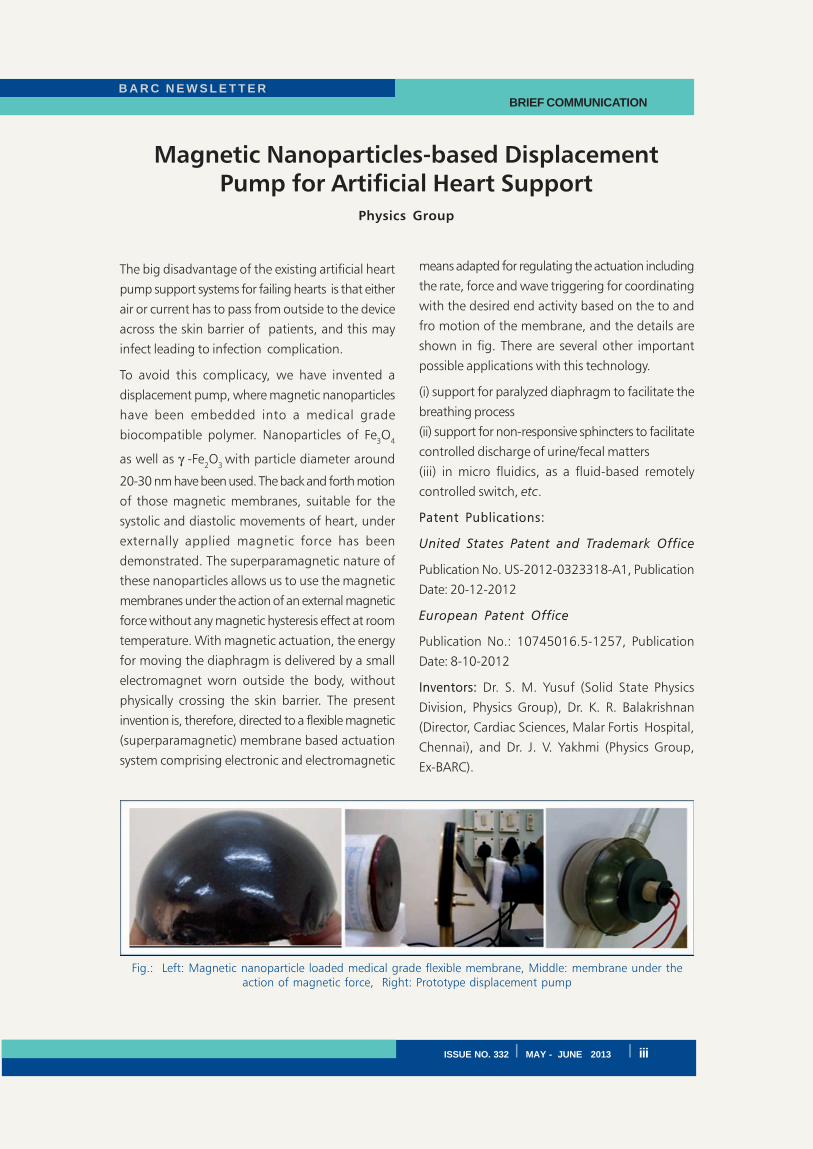
Fig.: Left: Magnetic nanoparticle loaded medical grade flexible membrane, Middle: membrane under theaction of magnetic force, Right: Prototype displacement pump
B A R C N E W S L E T T E RBRIEF COMMUNICATION
iv I ISSUE NO. 332 I MAY - JUNE 2013
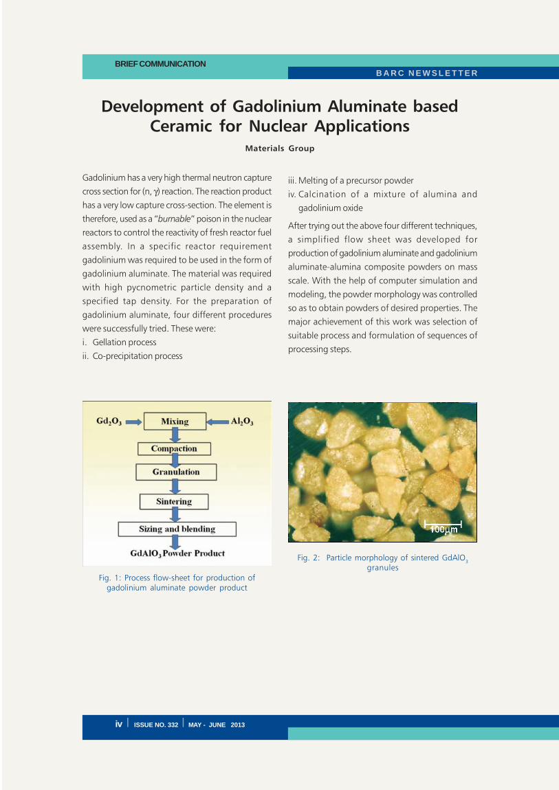
Development of Gadolinium Aluminate basedCeramic for Nuclear Applications
Materials Group
Gadolinium has a very high thermal neutron capture
cross section for (n, γ) reaction. The reaction product
has a very low capture cross-section. The element is
therefore, used as a “burnable” poison in the nuclear
reactors to control the reactivity of fresh reactor fuel
assembly. In a specific reactor requirement
gadolinium was required to be used in the form of
gadolinium aluminate. The material was required
with high pycnometric particle density and a
specified tap density. For the preparation of
gadolinium aluminate, four different procedures
were successfully tried. These were:
i. Gellation process
ii. Co-precipitation process
iii. Melting of a precursor powder
iv. Calcination of a mixture of alumina and
gadolinium oxide
After trying out the above four different techniques,
a simplified flow sheet was developed for
production of gadolinium aluminate and gadolinium
aluminate-alumina composite powders on mass
scale. With the help of computer simulation and
modeling, the powder morphology was controlled
so as to obtain powders of desired properties. The
major achievement of this work was selection of
suitable process and formulation of sequences of
processing steps.
Fig. 1: Process flow-sheet for production ofgadolinium aluminate powder product
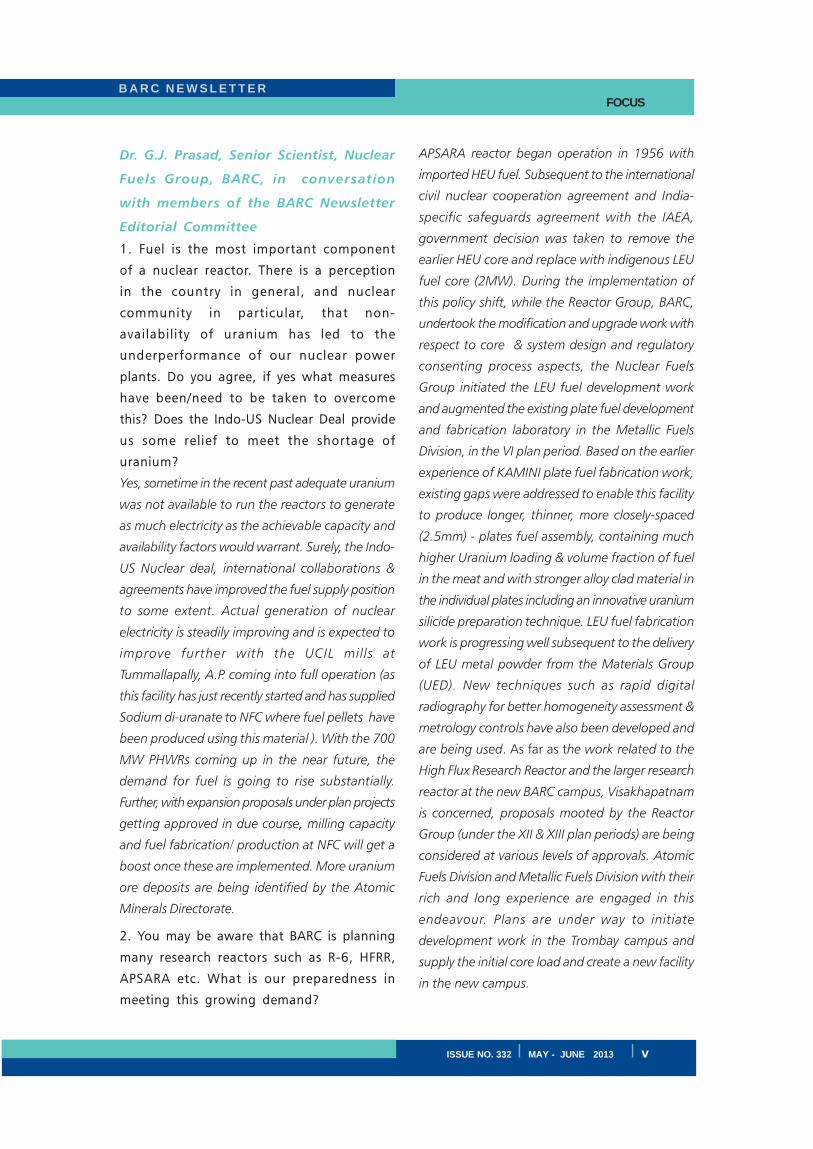
Fig. 2: Particle morphology of sintered GdAlO3
granules
B A R C N E W S L E T T E R
ISSUE NO. 332 I MAY - JUNE 2013 I v
FOCUS
Dr. G.J. Prasad, Senior Scientist, Nuclear
Fuels Group, BARC, in conversation
with members of the BARC Newsletter
Editorial Committee
1. Fuel is the most important component
of a nuclear reactor. There is a perception
in the country in general, and nuclear
community in particular, that non-
availability of uranium has led to the
underperformance of our nuclear power
plants. Do you agree, if yes what measures
have been/need to be taken to overcome
this? Does the Indo-US Nuclear Deal provide
us some relief to meet the shortage of
uranium?
Yes, sometime in the recent past adequate uranium
was not available to run the reactors to generate
as much electricity as the achievable capacity and
availability factors would warrant. Surely, the Indo-
US Nuclear deal, international collaborations &
agreements have improved the fuel supply position
to some extent. Actual generation of nuclear
electricity is steadily improving and is expected to
improve further with the UCIL mills at
Tummallapally, A.P. coming into full operation (as
this facility has just recently started and has supplied
Sodium di-uranate to NFC where fuel pellets have
been produced using this material ). With the 700
MW PHWRs coming up in the near future, the
demand for fuel is going to rise substantially.
Further, with expansion proposals under plan projects
getting approved in due course, milling capacity
and fuel fabrication/ production at NFC will get a
boost once these are implemented. More uranium
ore deposits are being identified by the Atomic
Minerals Directorate.
2. You may be aware that BARC is planning
many research reactors such as R-6, HFRR,
APSARA etc. What is our preparedness in
meeting this growing demand?
APSARA reactor began operation in 1956 with
imported HEU fuel. Subsequent to the international
civil nuclear cooperation agreement and India-
specific safeguards agreement with the IAEA,
government decision was taken to remove the
earlier HEU core and replace with indigenous LEU
fuel core (2MW). During the implementation of
this policy shift, while the Reactor Group, BARC,
undertook the modification and upgrade work with
respect to core & system design and regulatory
consenting process aspects, the Nuclear Fuels
Group initiated the LEU fuel development work
and augmented the existing plate fuel development
and fabrication laboratory in the Metallic Fuels
Division, in the VI plan period. Based on the earlier
experience of KAMINI plate fuel fabrication work,
existing gaps were addressed to enable this facility
to produce longer, thinner, more closely-spaced
(2.5mm) - plates fuel assembly, containing much
higher Uranium loading & volume fraction of fuel
in the meat and with stronger alloy clad material in
the individual plates including an innovative uranium
silicide preparation technique. LEU fuel fabrication
work is progressing well subsequent to the delivery
of LEU metal powder from the Materials Group
(UED). New techniques such as rapid digital
radiography for better homogeneity assessment &
metrology controls have also been developed and
are being used. As far as the work related to the
High Flux Research Reactor and the larger research
reactor at the new BARC campus, Visakhapatnam
is concerned, proposals mooted by the Reactor
Group (under the XII & XIII plan periods) are being
considered at various levels of approvals. Atomic
Fuels Division and Metallic Fuels Division with their
rich and long experience are engaged in this
endeavour. Plans are under way to initiate
development work in the Trombay campus and
supply the initial core load and create a new facility
in the new campus.
B A R C N E W S L E T T E RFOCUS
vi I ISSUE NO. 332 I MAY - JUNE 2013
3. On the NPPs front, BARC is playing a
major role in generating fuel for PFBR,
PHWRs and AHWR. The fuel compositions
and manufacturing procedures are different
for these fuels. What steps need to be taken
to meet these fuel challenges?
As you know, regular fuel requirement for the
Indian NPPs are met by the NFC, Hyderabad.
However, NFC & BARC (Nuclear Fuels Group,
Materials and Chemical Engineering Groups)
participate in a very active manner in the R & D
programme related to fuel and core structurals.
Also valuable Post Irradiation Examination work
related to PHWR and uranium & thorium fuels is
being done all these years and very interesting
findings have been reported with respect to fuel
microstructure, (features like grain size/growth,
bubble size & distribution), fission gas retention/
release), pin failure etc. apart from off-normal
behavior/response of fuel pin failure analysis, NDT
support etc. NFG also participates in collaborative
development work with NFC in the area of PHWR
fuels and AHWR fuel. Fabrication development
work is being carried out both at the BARC’s
Advanced Fuel Fabrication facility at Tarapur (AFFF)
and in RMD. However, new GB trains and facilities
have to be created for regular production of fuel
pins for the AHWR, once final decision is taken on
the fuel type and the reactor.
MOX fuel development and fabrication work on a
large scale is being done at AFFF since its
commissioning in the early nineties where BWR,
PHWR, FBTR mox fuels have been developed &
fabricated. PFBR Prototype 37 pin assembly for
irradiation in FBTR was made in AFFF which has
seen 112GWD peak burn up successfully. Regular
production of SS D-9 clad 21% PuO2 MOX fuel
pins is progressing satisfactorily and a large number
of fuel pins have already been delivered to IGCAR,
Kalpakkam, for storage and assembly fabrication
work by NFC. Production capacity is being
augmented and additional manpower has been
allotted on priority basis. Soon production of type
2 pins containing 28% PuO2 will commence once
the type 1 pins requirement is met. We at NFG are
thankful to NRB for the continuous supply of the
feed material and to NFC for the hardware & RU
supplies. We are confident of meeting the
schedules for the reactor attaining criticality and
raised power operations of PFBR.
4.What was the motive in going for carbide
fuels for our Fast Breeder Test Reactor
(FBTR)? Subsequently, we have developed
oxide fuels for our 500 MWe PFBR.
The FBTR was based on Rapsodie design under the
French collaboration using MOX fuel (70% HEU
oxide with 85% enrichment and 30% PuO2). After
the Peaceful Nuclear Explosion in 1974, we were
entirely on our own at a time when the only option
available was to meet the entire fissile requirement
using plutonium. Our enrichment programme was
under development. There were specific
performance related issues with plutonium rich
MOX fuel of the required PuO2 content (76%).
Especially the formation of low density compounds
with sodium & fuel post clad breach. Important
fuel properties like thermal conductivity of MOX
with this composition would be poor and fuel
oxygen potential would be higher as more and
more noble fission products are formed with
increased burnup of plutonium which could lead
to further problems. The plutonium rich carbide
fuel development work carried out in the
Radiometallurgy Division in the early eighties,
showed very encouraging results and fuel-coolant
compatibility experiments also produced good
results. Results of calculations for clad carburization
during irradiation done in collaboration with
Materials Group were also encouraging. And to
top it all, the big bonus was lower fissile
B A R C N E W S L E T T E R
ISSUE NO. 332 I MAY - JUNE 2013 I vii
FOCUS
requirement. So it was a sort of win-win situation
in favour of Pu-rich mixed carbide fuels at that time.
However, large scale production of mixed carbide
fuel for commercial fast reactor is an extremely
challenging task. As the core size is large in this
case, much lower level of plutonium in the mox is
warranted say 20 to 30% which is a well proven
composition. Also fabrication experience had
already been gained at the AFFF, Tarapur while
making MOX fuel for FBTR hybrid core and the
prototype pin assembly of PFBR type for irradiation
test in FBTR as mentioned earlier.
5. In this context, we have developed the
reprocessing technologies for carbide fuels
and closed FBTR fuel cycle as demonstration
effort which was indeed a difficult task.
Now we have introduced oxide fuels, do
you think we have acquired expertise/
availability to handle the fuel from proposed
commercial fast reactors with indigenously
reprocessed plutonium?
As already explained, this work is progressing very
well at AFFF, Tarapur and we at NFG are confident
of meeting the challenges of fuel schedules of PFBR.
6. From oxide fuels, it is planned to shift to
metallic fuels for future FBR. In what way
will this shift to metallic fuels, be beneficial
for India’s nuclear power programme?
As you know the oxide-fuelled Fast reactors are
marginal breeders and rapid nuclear power
generation capacity build up would not be feasible.
However it would provide a sound footing for the
demonstration of a commercial scale liquid metal
cooled fast reactor operation to enable the growth
of the second stage of our nuclear programme in a
substantial way. If by that time pyro-electro-
reprocessing and remote fuel fabrication technology
work being done in the IGCAR attains the maturity
level to initiate integrated metal fuelled fast reactor
& fuel cycle programme, the country would be on
a rapid nuclear electricity generation capacity
growth path as metal fuels offer much higher
breeding ratios and efficiency and lower doubling
time & volumes of high level nuclear waste etc.
7.The third stage of the Indian Nuclear
Programme envisages large scale use of
thorium as the fertile component of fuel.
When do you think that use of thorium on
a commercial scale, with breeding ratios
greater than one to make Fast Reactor
Technology self sustainable, will be
reasonably feasible? There are conflicting
reports from the international community
and what should be our reaction to this.
The fast reactor thorium fuel cycle is yet to be
demonstrated on a large scale. As you know
nuclear power generation option has been going
through cycles of popularity, acceptance &
rejection internationally and seen both as a panacea
for the energy-hungry world and also feared as a
source of big trouble by some people. This together
with “incidents” has given rise to wide fluctuations
in the pricing of uranium in the international
market. Fortunately, in India the situation has been
relatively steady and we in the nuclear community
have been getting good sustained support. Perhaps
our outreach programmes and not so visible R&D
contributions to the non-power sector for societal
benefits have helped us.
It is well known that to initiate thorium programme
and grow, seed fuel on a significant scale and large
quantities would be required. Moreover remote
handling techniques and equipment have to be
developed and industrially produced to meet the
requirements at various stages. That will take some
time. In the meantime it is necessary for us to
achieve very significant progress in the second
stage where Uranium utilization can be substantially
enhanced to 60% (from under 1% in the first stage)
B A R C N E W S L E T T E RFOCUS
viii I ISSUE NO. 332 I MAY - JUNE 2013
by successfully recycling thrice in the fast reactors
preferably using metallic fuels as early as possible.
Even this would take some more time although
progress has been made in R&D areas both in BARC
as well as in IGCAR.
8. During the years that you participated in
the fuel development programme, the
emphasis has shifted from research to
development of advanced fuels. As a
metallurgist, kindly highlight the
achievements in this area.
Development and fabrication campaigns are
examples of very good team work. This in my
opinion is the main achievement and high point.
Of course my colleagues in NFG have accepted
challenges and delivered fuel to many reactor types
over a long period and have helped create industrial
scale facilities. The pioneering leaders have laid a
very effective and mutually satisfying work culture
which is still continuing. We also have good R&D
multidisciplinary teams in all the divisions. Work
goes on across these barriers.
9. Development of new structural materials
and fuel has good scope. What are your
suggestions to accelerate the programme?
In the areas of structural materials we should
strengthen processing & fabrication. We should also
have a good MTR (Materials Testing Reactor) in
addition to access offered for experiments under
international collaborations. We already have a
strong PIE team.
10. What is your opinion on making available
small research reactors like APSARA, in
universities and expanding research
programme, production of isotopes etc.?
Definitely this would be very helpful in increasing
the size and spread of nuclear science, technology
and applications activities. However, this would take
time as new systems have to be put in place. A lot
more people have to be motivated in universities
and institutions.
11. The BARC Newsletter has been the
preferred channel of communication for
BARC Scientists and Engineers for almost
three decades now and in the last three
years, it has undergone a major
metamorphosis. Any suggestions to improve
its quality and content?
I feel, “Reader’s Forum” has to be strengthened
where they could comment and make suggestions.
12. What are your personal memories that
you would like to share so that young
scientists and engineers get motivated and
what is your future vision for BARC? Where
do you see BARC 20 years from now?
I cherish the contribution & association of my friends
and team members. All of them have enriched
me and have stood by me and tolerated my failings
and shortcomings. I also thank my seniors and
mentors who have supported and guided me all
these years.
The Younger generation is skilled, practical,
equipped and has better background. However, it
would take them a long way if virtues of patience
and tolerance are also practised by them.
We have a strong road map and with better and
faster implementation of plan projects, I am sure,
BARC would have a very bright future both at
Trombay and Visakapatnam
I thank you all for giving me this opportunity to
discuss with you.
B A R C N E W S L E T T E R RESEARCH ARTICLE
ISSUE NO. 332 I MAY - JUNE 2013 I 1
Development of ICMC-1.0 Monte Carlo Code forNeutron and Particle Transport
H. KumawatNuclear Physics Division
and
P.P.K. Venkata
Computer Division
Abstract
The Intra-nuclear Cascade Monte Carlo (ICMC) code for transport of neutrons, protons, pions and heavy
ions has been developed at Nuclear Physics Division, BARC in the last few years, and further developments
are underway. We have developed the code for low energy neutron transport using pointwise cross section
data below 20 MeV of neutron energy. Constructive Solid Geometry model, based on solid bodies, is
adopted to construct geometry. A module for repetitive structure for lattice, core calculations in reactors
and detector simulations is developed. A Graphical User Interface (GUI) has been incorporated for making
the input, construction and visualization of the geometry and analysis of the output. The code has been
validated for simulating benchmarks of accelerator driven sub-critical systems, neutron shielding, heat and
neutron flux distribution, and keff
of the critical and sub-critical assemblies.
Introduction
The statistical nature of nuclear reactions and
propagation of particles through matter can be best
simulated using the Monte Carlo method. This
method is most suited to solve multi-dimensional
problems, involving complex geometries and
variation of cross sections with energy. The accuracy
is limited only by the uncertainty in the input data
such as cross sections. It provides a solution to the
integral equation using random sampling in space
[1]. The Monte Carlo method, used in simulation
of nuclear reactions, is based upon generation of
individual particle histories using random sampling
methods. It can provide estimates of desired
quantities such as keff
or flux which would be
obtainable from a solution to the transport equation
using random sampling in space without obtaining
a detailed or complete solution of the transport
equation. The probability of interaction is simulated
with the help of random numbers and cross sections
and these are primary input quantities which
determine the accuracy of the method.
There are several Monte carlo codes named GEANT4
[2], FLUKA [3], PHITS [4], MCNP [5], MARS [6] for
particle transport in matter. Some of these codes
(GEANT4, FLUKA, and MARS) are suitable for
detector optimization and high energy physics
simulations. The other Monte Carlo codes viz. MCNP
and TRIPOLI [7] use the continuous energy neutron
cross-sections and are suitable for reactor
simulations.
The Monali code [8] developed several years back
uses multigroup cross section data library. Thus a
need was felt to develop a continuous energy code
in this centre.
The development of ICMC code along with GUI
was started a couple of years ago. We have adopted
Constructive Solid Geometry (CSG) model [9] for
the construction of Geometry. Repetitive structure
is introduced to perform lattice calculations.
Continuous energy cross-section representation is
used to take into account the details of the
resonance structure. The article is organized as
follows: Section 2 describes the implementation of
B A R C N E W S L E T T E RRESEARCH ARTICLE
2 I ISSUE NO. 332 I MAY - JUNE 2013
the geometry and the neutron transport is detailed
in Section 3. Sec. 4 contains a description about
the GUI. The high energy part of the code is
described in Sec. 5. Conclusions and further
developments are discussed in Sec. 6.
Construction of Geometry
The most important and difficult task in the Monte
Carlo code is to build a complicated geometry in a
user friendly manner. We have chosen the CSG
model to build the geometry. In this model, there
are simple basic geometrical bodies viz. Sphere,
Cylinder, Box, Cone, Ellipse, Hexagon etc. Boolean
operations (Union, subtraction and intersection) are
used to construct complex zones using these bodies.
We must also provide a universe that contains all
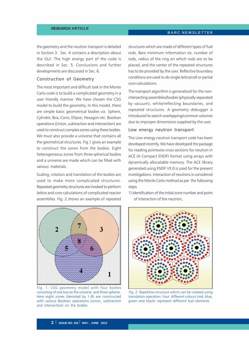
the geometrical structures. Fig.1 gives an example
to construct the zones from the bodies. Eight
heterogeneous zones from three spherical bodies
and a universe are made which can be filled with
various materials.
Scaling, rotation and translation of the bodies are
used to make more complicated structures.
Repeated geometry structures are invoked to perform
lattice and core calculations of complicated reactor
assemblies. Fig. 2 shows an example of repeated
structures which are made of different types of fuel
rods. Bare minimum information viz. number of
rods, radius of the ring on which rods are to be
placed, and the center of the repeated structures
has to be provided by the user. Reflective boundary
conditions are used to do single lattice/cell or partial
core calculations.
The transport algorithm is generalized for the non-
intersecting assemblies/bodies (physically separated
by vacuum), white/reflecting boundaries, and
repeated structures. A geometry debugger is
introduced to search overlapping/common volumes
due to improper dimensions supplied by the user.
Low energy neutron transport
The Low energy neutron transport code has been
developed recently. We have developed the package
for reading pointwise cross sections for neutron in
ACE (A Compact ENDF) format using arrays with
dynamically allocatable memory. The ACE library
generated using ENDF VII.0 is used for the present
investigations. Interaction of neutrons is considered
using the Monte Carlo method as per the following
steps.
1) Identification of the initial zone number and point
of interaction of the neutron,
Fig. 1: CSG geometry model with four bodiesconsisting of one box as the universe and three spheres.Here eight zones (denoted by 1-8) are constructedwith various Boolean operations (union, subtractionand intersection) on the bodies
Fig. 2: Repetitive structure which can be created usingtranslation operation. Four different colours (red, blue,green and black) represent different fuel elements
B A R C N E W S L E T T E R RESEARCH ARTICLE
ISSUE NO. 332 I MAY - JUNE 2013 I 3
2) Selection of the collision nuclide,
3) Type of interaction (elastic, non-elastic, fission,
capture, others).
ICMC-1.0 assigns the X, Y, Z, cosè, sinö, cosö,
energy (MeV), charge, and mass(MeV/C2)
coordinates with each neutron. The code identifies
the zone number constituted from the given bodies
of the configuration defined in the input file. The
macroscopic cross section is calculated to get the
mean free path in the identified zone which is used
to sample the distance to the next collision. The
nuclide with which the collision takes place is
identified using the fact that probability of
interaction with a given nuclide is proportional to
the total macroscopic cross-section of that nuclide.
The final search is made for reaction type with the
identified nuclide. One complete history consists of
nuclear interactions; secondary particle production
and their transport till predefined cutoff energies
are reached. The neutron cutoff energy is defined
to be 1×10-12 MeV in the present version of the
code.
The criticality calculations in ICMC-1.0 are based
on four methods (neutron population, Collision
Estimator, Absorption Estimator, and Track Length
Estimator). The keff
is a ratio between the number
of neutrons in successive generations in a fission
chain reaction. For critical systems, keff
= 1, for
sub-critical systems, keff
<1 and for supercritical
systems, keff
>1. The number of neutrons in
successive generations is obtained from number of
neutrons generated by fission. Whenever (n, xn)
reactions occur, the neutrons generated are again
transported within the same fission cycle. At present
fission source points as well as neutron generations
are as usual allowed as other reactions but stored
for the next cycle. At the end of each cycle the total
weight is maintained constant by increasing or
decreasing weight of neutrons in case of (keff
>1)
and (keff
< 1), respectively. The maximum likelihood
keff
of the system from all four estimators is calculated
using weighted mean where weight is given by
inverse of the squared error from individual
estimators. Error in the mean keff
is also calculated
similarly. The prompt energy spectrum is used in
place of the delayed energy spectrum in case the
latter is not available. The criticality calculation
requires number of inactive cycles which need to
be skipped to get the fundamental mode of fission
source, active cycles for actual keff
, and number of
source neutrons. Mono energetic neutron can be
defined very easily in the input file and spectrum
can be provided through a separate file. In case of
high energy proton or other beam, the source
distribution is generated using the high energy part
of the code and that is transported below 20 MeV.
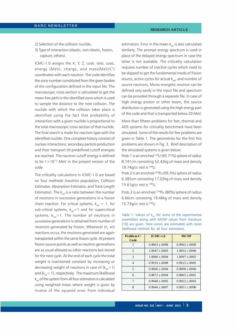
More than fifteen problems for fast, thermal and
ADS systems for criticality benchmark have been
simulated. Some of the results for few problems are
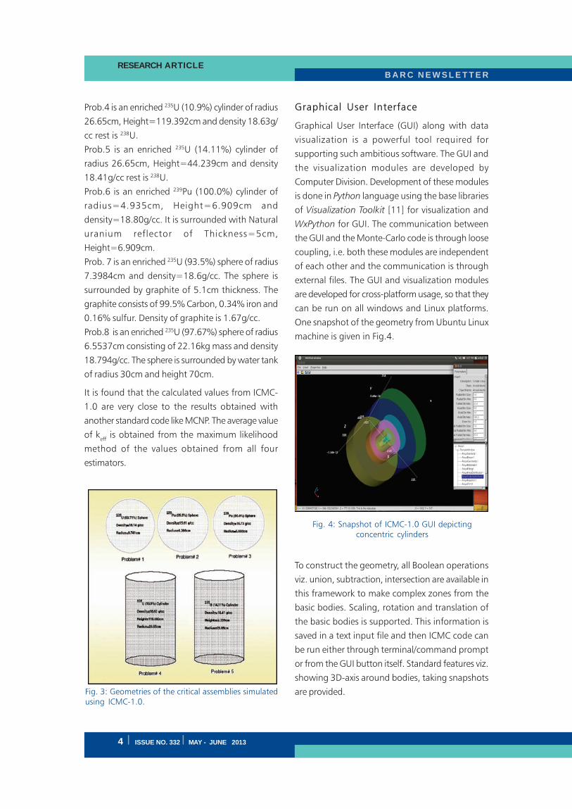
given in Table 1. The geometries for the first five
problems are shown in Fig. 3. Brief description of
the simulated systems is given below:
Prob.1 is an enriched 235U (93.71%) sphere of radius
8.741cm consisting 52.42kg of mass and density
18.74g/cc rest is 238U.
Prob.2 is an enriched 239Pu (95.5%) sphere of radius
6.385cm consisting 17.02kg of mass and density
15.61g/cc rest is 240U.
Prob.3 is an enriched 239Pu (80%) sphere of radius
6.66cm consisting 19.46kg of mass and density
15.73g/cc rest is 240U.
Problem # / Code
ICMC-1.0 MCNP
1 0.9963 ±.0008 0.9962 ±.0009
2 1.0047 ±.0003 1.0052 ±.0006
3 1.0086 ±.0004 1.0097 ±.0002
4 0.9910 ±.0008 0.9915 ±.0005
5 0.9906 ±.0004 0.9908 ±.0006
6 0.8872 ±.0004 0.8865 ±.0001
7 0.9948 ±.0005 0.9952 ±.0003
8 0.9946 ±.0007 0.9951 ±.0006
Table 1: Values of keff
for some of the experimental
assemblies along with MCNP values from literature
[10] are given. Here errors are estimated with most
likelihood method for all four estimators
B A R C N E W S L E T T E RRESEARCH ARTICLE
4 I ISSUE NO. 332 I MAY - JUNE 2013
Prob.4 is an enriched 235U (10.9%) cylinder of radius
26.65cm, Height=119.392cm and density 18.63g/
cc rest is 238U.
Prob.5 is an enriched 235U (14.11%) cylinder of
radius 26.65cm, Height=44.239cm and density
18.41g/cc rest is 238U.
Prob.6 is an enriched 239Pu (100.0%) cylinder of
radius=4.935cm, Height=6.909cm and
density=18.80g/cc. It is surrounded with Natural
uranium reflector of Thickness=5cm,
Height=6.909cm.
Prob. 7 is an enriched 235U (93.5%) sphere of radius
7.3984cm and density=18.6g/cc. The sphere is
surrounded by graphite of 5.1cm thickness. The
graphite consists of 99.5% Carbon, 0.34% iron and
0.16% sulfur. Density of graphite is 1.67g/cc.
Prob.8 is an enriched 235U (97.67%) sphere of radius
6.5537cm consisting of 22.16kg mass and density
18.794g/cc. The sphere is surrounded by water tank
of radius 30cm and height 70cm.
It is found that the calculated values from ICMC-
1.0 are very close to the results obtained with
another standard code like MCNP. The average value
of keff
is obtained from the maximum likelihood
method of the values obtained from all four
estimators.
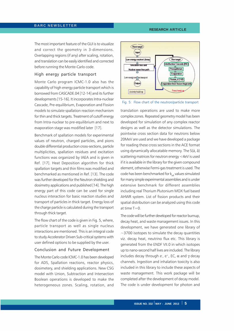
Graphical User Interface
Graphical User Interface (GUI) along with data
visualization is a powerful tool required for
supporting such ambitious software. The GUI and
the visualization modules are developed by
Computer Division. Development of these modules
is done in Python language using the base libraries
of Visualization Toolkit [11] for visualization and
WxPython for GUI. The communication between
the GUI and the Monte-Carlo code is through loose
coupling, i.e. both these modules are independent
of each other and the communication is through
external files. The GUI and visualization modules
are developed for cross-platform usage, so that they
can be run on all windows and Linux platforms.
One snapshot of the geometry from Ubuntu Linux
machine is given in Fig.4.
To construct the geometry, all Boolean operations
viz. union, subtraction, intersection are available in
this framework to make complex zones from the
basic bodies. Scaling, rotation and translation of
the basic bodies is supported. This information is
saved in a text input file and then ICMC code can
be run either through terminal/command prompt
or from the GUI button itself. Standard features viz.
showing 3D-axis around bodies, taking snapshots
are provided.Fig. 3: Geometries of the critical assemblies simulatedusing ICMC-1.0.
Fig. 4: Snapshot of ICMC-1.0 GUI depictingconcentric cylinders
B A R C N E W S L E T T E R RESEARCH ARTICLE
ISSUE NO. 332 I MAY - JUNE 2013 I 5
The most important feature of the GUI is to visualize
and correct the geometry in 3-dimensions.
Overlapping regions (if any) after scaling, rotation,
and translation can be easily identified and corrected
before running the Monte-Carlo code.
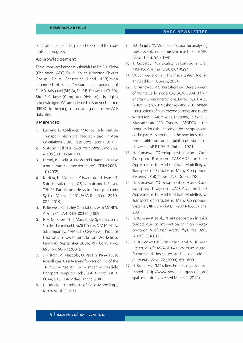
High energy particle transport
Monte Carlo program ICMC-1.0 also has the
capability of high energy particle transport which is
borrowed from CASCADE.04 [12-14] and its further
developments [15-16]. It incorporates Intra-nuclear
Cascade, Pre-equilibrium, Evaporation and Fission
models to simulate spallation reaction mechanism
for thin and thick targets. Treatment of cutoff energy
from Intra-nuclear to pre-equilibrium and next to
evaporation stage was modified later [17].
Benchmark of spallation models for experimental
values of neutron, charged particles, and pions
double differential production cross-sections, particle
multiplicities, spallation residues and excitation
functions was organized by IAEA and is given in
Ref. [17]. Heat Deposition algorithm for thick
spallation targets and thin films was modified and
benchmarked as mentioned in Ref. [13]. The code
was further developed for the Neutron shielding and
dosimetry applications and published [14]. The high
energy part of this code can be used for single
nucleus interaction for basic reaction studies and
transport of particles in thick target. Energy loss of
the charge particle is calculated during the transport
through thick target.
The flow chart of the code is given in Fig. 5, where,
particle transport as well as single nucleus
interactions are mentioned. This is an integral code
to study Accelerator Driven Sub-critical systems with
user defined options to be supplied by the user.
Conclusion and Future Development
The Monte Carlo code ICMC-1.0 has been developed
for ADS, Spallation reactions, reactor physics,
dosimetery, and shielding applications. New CSG
model with Union, Subtraction and Intersection
Boolean operations is developed to make the
heterogeneous zones. Scaling, rotation, and
translation operations are used to make more
complex zones. Repeated geometry model has been
developed for simulation of any complex reactor
designs as well as the detector simulations. The
pointwise cross section data for neutrons below
20MeV are used and we have developed a package
for reading these cross sections in the ACE format
using dynamically allocatable memory. The S(á, â)
scattering matrices for neutron energy <4eV is used
if it is available in the library for the given compound
element, otherwise Fermi-gas treatment is used. The
code has been benchmarked for keff
values simulated
for many simple experimental assemblies and is under
extensive benchmark for different assemblies
including real Thorium Plutonium MOX fuel based
AHWR system. List of fission products and their
spatial distribution can be analyzed using this code
at time T=0.
The code will be further developed for reactor burnup,
decay heat, and waste management issues. In this
development, we have generated one library of
~3700 isotopes to simulate the decay quantities
viz. decay heat, neutrino flux etc. This library is
generated from the ENDF VII.0 in which isotopes
up to nano-second half lives are included. The library
includes decay through e-, e+, EC, α and γ decay
channels. Ingestion and inhalation toxicity is also
included in this library to include these aspects of
waste management. This work package will be
completed after the development of decay model.
The code is under development for photon and
Fig. 5: Flow chart of the neutron/particle transport
B A R C N E W S L E T T E RRESEARCH ARTICLE
6 I ISSUE NO. 332 I MAY - JUNE 2013
electron transport. The parallel version of the code
is also in progress.
Acknowledgement
The authors are immensely thankful to Dr. R.K. Sinha
(Chairman, AEC) Dr. S. Kailas (Director, Physics
Group), Dr. A. Chatterjee (Head, NPD) who
supported this work. Constant encouragement of
Dr. P.D. Krishnani (RPDD), Dr. S.B. Degweker (ThPD),
Shri S.K. Bose (Computer Division), is highly
acknowledged. We are indebted to Shri Anek Kumar
(RPDD) for helping us in reading one of the ACE
data files.
References
1. Lux and L. Koblinger, “Monte Carlo particle
Transport Methods: Neutron and Photon
Calculaions”, CRC Press, Boca Raton (1991).
2. S. Agostinelli et al. Nucl. Instr. Meth. Phys. Res.
A 506 (2003) 250-303.
3. Ferrari, P.R. Sala, A. Fasso and J. Ranft, “FLUKA:
a multi-particle transport code”, CERN 2005-
10 (2005).
4. K. Niita, N. Matsuda, Y. Iwamoto, H. Iwase, T.
Sato, H. Nakashima, Y. Sakamoto and L. Sihver,
“PHITS: Particle and Heavy Ion Transport code
System, Version 2.23”, JAEA-Data/Code 2010-
022 (2010).
5. R. Brewer, “Criticality Calculations with MCNP5:
A Primer”, LA-UR-09-00380 (2009).
6. N.V. Mokhov, “The Mars Code System User’s
Guide”, Fermilab-FN-628 (1995); N.V. Mokhov,
S.I. Striganov, “MARS15 Overview”, Proc. of
Hadronic Shower Simulation Workshop,
Fermilab, September 2006, AIP Conf. Proc.
896, pp. 50-60 (2007).
7. J. P. Both, A. Mazzolo, O. Petit, Y. Peneliau, B.
Roesslinger: User Manual for version 4.3 of the
TRIPOLI-4 Monte Carlo method particle
transport computer code, CEA-Report: CEA-R-
6044, DTI, CEA/Saclay, France, 2003.
8. L. Donald, “Handbook of Solid Modelling”,
McGraw Hill (1995).
9. H.C. Gupta, “A Monte Carlo Code for analyzing
fuel assemblies of nuclear reactors”, BARC
report 1543, 54p, 1991.
10. T. Goorley, “Criticality calculations with
MCNP5: A Primer, LA-UR-04-0294”
11. W. Schroeder et. al., The Visualization Toolkit,
Third Edition, Kitware, 2004.
12. H. Kumawat, V. S. Barashenkov, ‘Development
of Monte Carlo model CASCADE-2004 of high
energy nuclear interactions, Euro. Phys. J. A 26
(2005) 61; V.S. Barashenkov and V.D. Toneev,
“Interactions of high-energy particles and nuclei
with nuclei”. Atomizdat, Moscow, 1972; S.G.
Mashnik and V.D. Toneev, “MODEX – the
program for calculations of the energy spectra
of the particles emitted in the reactions of the
pre-equilibrium and equilibrium statistical
decays”, JINR P4-9417, Dubna, 1974.
13. H. Kumawat, “Development of Monte-Carlo
Complex Program CASCADE and its
Applications to Mathematical Modelling of
Transport of Particles in Many Component
Systems”, PhD Thesis, JINR, Dubna, 2004.
14. H. Kumawat, “Development of Monte-Carlo
Complex Program CASCADE and its
Applications to Mathematical Modelling of
Transport of Particles in Many Component
Systems”, JINR preprint E11-2004-166, Dubna,
2004.
15. H. Kumawat et al., “Heat deposition in thick
targets due to interaction of high energy
protons”, Nucl. Instr. Meth. Phys. Res. B266
(2008): 604-612.
16. H. Kumawat P. Srinivasan and V. Kumar,
“Extension of CASCADE.04 to estimate neutron
fluence and dose rates and its validation”,
Pramana J. Phys. 72 (2009): 601-609.
17. H. Kumawat, ‘IAEA Benchmark of spallation
models’. http://www-nds.iaea.org/spallations/
spal_mdl.html (accessed March 1, 2010).
B A R C N E W S L E T T E R RESEARCH ARTICLE
ISSUE NO. 332 I MAY - JUNE 2013 I 7
Development of Catalyst for Decomposition ofSulfuric Acid: The Energy Intensive Step in
Sulfur-Iodine Thermochemical Cycle forHydrogen Generation using Nuclear Heat
A.M. Banerjee, M.R. Pai, A.K. Tripathi, S.R. Bharadwaj and D. Das
Chemistry Division
and
P.K. Sinha
ECMS, BARC, Vashi Complex, Navi Mumbai
Abstract
We report here the in-house catalyst development work undertaken at Chemistry Division on sulfuric acid
decomposition reaction, the most endothermic step of Sulfur-Iodine (S-I) thermochemical cycle being
pursued in the DAE for large scale hydrogen generation using the proposed Compact High Temperature
Reactor (CHTR). Various catalyst systems like iron oxide, substituted iron oxide and ferrites were evaluated
in the temperature range of 600-825°C employing indigenously developed glass setups. Owing to higher
activity, iron oxide based catalysts were investigated in detail for their possible deployment in an integrated
glass setup of S-I process at Chemical Technology Division. Comparative studies on iron oxide based
catalysts (Fe2O
3 &
Fe
1.8Cr
0.2O
3) with a commercial Pt catalyst (Pt/Al
2O
3) have demonstrated that both Cr-
substituted and un-substituted iron oxides are active for catalytic decomposition of sulfuric acid and are
comparable to Pt/Al2O
3 at temperatures above 750 °C and may therefore be a good substitute for the noble
metal catalyst. The study has also established the poison resistant behavior of Fe1.8
Cr0.2
O3 catalyst in presence
of I-/I2 impurities which are likely to be present in the sulfuric acid phase produced in the Bunsen section of
S-I process.
Introduction
Exploration of alternate energy resources has attained
greater significance in recent times due to ever-
increasing worldwide energy demands, depleting
fossil resources and growing concern about global
warming caused by the emission of greenhouse
gases. Hydrogen, being a clean and renewable
energy carrier, offers a promising alternative to the
fossil fuels, particularly for the transport applications
using fuel cell technology. At present, it is largely
produced by steam reforming of hydrocarbons such
as steam methane reforming (SMR) but the process
suffers from a major drawback i.e. generation of
CO2, a green house gas, as a by-product. More
recently, two processes namely, thermochemical
splitting and high temperature electrolysis of water
have shown great potential towards efficient
production of hydrogen on industrial scale1. Energy
requirements for these processes are expected to be
met by high temperature nuclear reactor or solar
concentrator as viable alternatives to carbonaceous
resources.
While thermal decomposition of water requires
a temperature in excess of 2500°C (H2O=H
2+
1/2O2 ; ΔG0 = 237 kJ/mol), thermochemical cycles
produce hydrogen from water through a number
of chemical reactions involving intermediates that
are fully recyclable1,2. Among various
thermochemical cycles proposed for hydrogen
generation, Sulphur – Iodine (S-I) process is widely
considered as a potential choice to produce hydrogen
on industrial scale due to its attractive features such
as higher energy efficiency (~47%), all fluids process
B A R C N E W S L E T T E RRESEARCH ARTICLE
8 I ISSUE NO. 332 I MAY - JUNE 2013
and adaptability with a high temperature nuclear
reactor (~ 950°C)3. S-I thermochemical cycle,
originally proposed by General Atomics, involves
the following chemical reactions:
I2 (l) + SO
2 (g) + 2H
2O (l) → 2HI (l) + H
2SO
4 (l);
Bunsen Step (70 - 120°C) ...(1)
H2SO
4 (l) → SO
2 (g) + H
2O (g) + 1/2O
2 (g); Sulfuric
Acid Decomposition Step (700 - 900°C)...(2)
2HI (l) → I2 (g) + H
2 (g); Hydriodic Acid
Decomposition Step (300 - 450°C)...(3)
Net reaction: H2O (l) → H
2 (g) + 1/2O
2 (g) ...(4)
The free energy required for the net reaction is
provided by the free energies of the individual
reactions of the S-I thermochemical cycle. The most
energy demanding step of this cycle namely, sulfuric
acid decomposition (Eqn. 2) effectively utilizes the
intense heat flux from the high temperature nuclear
reactor and kinetics of this step has a strong influence
on the efficiency of S-I thermochemical cycle.
Catalytic decomposition of sulfuric acid
Decomposition of sulphuric acid (Eqn.2) occurs in
two steps, one non-catalytic and the other a catalytic
one, as shown below:
H2SO
4 (l) → H
2O (g) + SO
3 (g) (~ 450°C) ; Non-
catalytic ...(5)
SO3 (g) → SO
2 (g) + 1/2O
2 (g) (800- 900°C) ; Catalytic
...(6)
The thermal decomposition of SO3 encounters a large
kinetic barrier4 (Ea = 73 kJ mol-1) and even at high
temperatures such as that of the coolant gas (600 –
950°C) carrying heat from nuclear reactor it does
not take place without a catalyst. Thus to achieve
high levels of chemical conversion in a rapid manner,
an efficient catalyst would be essential for the SO3
decomposition reaction.
Work reported in literature
Various catalysts reported to be active for
decomposition of sulfuric acid include noble metal,
metal oxides and mixed- metal oxides4-9. Besides
activity, the stability of the catalyst is also very
important as the reaction environment is extremely
hostile like high temperatures, presence of aggressive
chemicals, including high temperature steam,
oxygen and sulphur oxides. While noble metal
catalysts like Pt/ZrO2, Pt/TiO
2, Pt/BaSO
4 and Pt/A1
2O
3
are reported to be quite active for SO3 decomposition
reaction, phenomenon like oxidation of noble metal,
sintering of metal particles, loss of active metal,
sulfation of the support, have been observed during
their long term use leading to their deactivation5,7.
The metal oxides were reported to be active only
over the temperature region in which the
corresponding sulfates were unstable. Tagawa and
Endo6 have compared the activity of metal oxides
for the sulfuric acid decomposition in the range of
600-950°C and found the order as follows: Pt ≈Cr
2O
3 > Fe
2O
3 > CeO
2 > NiO > Al
2O
3. In a recent
study involving complex metal oxides Ginosar et al8
have reported CuFe2O
4 and 2CuO.Cr
2O
3 to be more
active than 1.0 wt% Pt/TiO2 at temperatures above
850°C.
Work at Chemistry Division, BARC
In view of the availability of high-grade heat from
the proposed Compact High Temperature Reactor
(CHTR), work on S-I cycle started at BARC in 2006.
Studies on catalytic decomposition of sulfuric acid
were also initiated in the same year at Chemistry
Division with an objective to develop non-noble
metal catalysts which are both active and stable
under harsh reaction conditions existing over the
long hours of operation of reactor heat extraction
cum acid decomposition step of the S-I cycle. Various
oxides/mixed oxides and ferrites were evaluated for
this purpose9-11. Among these, iron oxide based
catalysts (Fe2O
3 &
Fe
1.8Cr
0.2O
3) were found to be
promising and were investigated in detail for their
possible deployment in an integrated glass setup
for S-I process at Chemical Technology Division
(CTD).
Following is an overview of the work related to
catalytic decomposition of sulfuric acid carried out
at Chemistry Division in recent past:
B A R C N E W S L E T T E R RESEARCH ARTICLE
ISSUE NO. 332 I MAY - JUNE 2013 I 9
( i ) Preparation of catalysts
Iron oxide and chromium substituted iron oxide
(Fe1.8
Cr0.2
O3) catalysts were synthesized by
precipitation/co-precipitation routes employing
respective nitrates as metal precursors and
ammonium hydroxide as a precipitating agent
followed by drying at 80°C in air oven and calcination
at 700 °C9. The synthesized powder samples of the
catalysts were processed in the granular form (4-6
mm) using polyvinyl alcohol (PVA) as a binder10.
ECMS, Vashi, Navi-Mumbai, established the
fabrication procedure of Fe2O
3 & Fe
1.8Cr
0.2O
3
granules. The ferrites (AFe2O
4, A = Co, Ni, Cu) were
synthesized by gel combustion method using
aqueous solution of corresponding metal nitrates
and glycine (NH2CH
2COOH) as per the procedure
described elsewhere11.
( i i ) Development of acid decomposition
setups
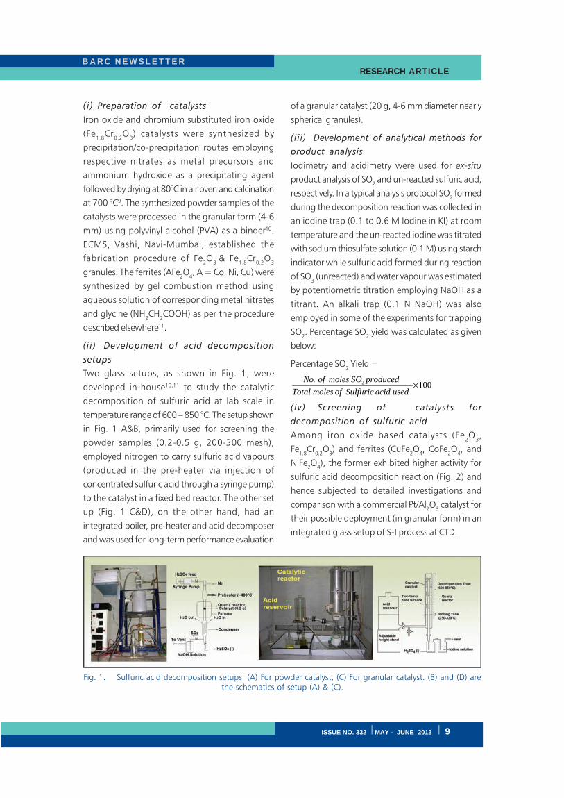
Two glass setups, as shown in Fig. 1, were
developed in-house10,11 to study the catalytic
decomposition of sulfuric acid at lab scale in
temperature range of 600 – 850 °C. The setup shown
in Fig. 1 A&B, primarily used for screening the
powder samples (0.2-0.5 g, 200-300 mesh),
employed nitrogen to carry sulfuric acid vapours
(produced in the pre-heater via injection of
concentrated sulfuric acid through a syringe pump)
to the catalyst in a fixed bed reactor. The other set
up (Fig. 1 C&D), on the other hand, had an
integrated boiler, pre-heater and acid decomposer
and was used for long-term performance evaluation
of a granular catalyst (20 g, 4-6 mm diameter nearly
spherical granules).
( i i i ) Development of analytical methods for
product analysis
Iodimetry and acidimetry were used for ex-situ
product analysis of SO2 and un-reacted sulfuric acid,
respectively. In a typical analysis protocol SO2 formed
during the decomposition reaction was collected in
an iodine trap (0.1 to 0.6 M Iodine in KI) at room
temperature and the un-reacted iodine was titrated
with sodium thiosulfate solution (0.1 M) using starch
indicator while sulfuric acid formed during reaction
of SO3 (unreacted) and water vapour was estimated
by potentiometric titration employing NaOH as a
titrant. An alkali trap (0.1 N NaOH) was also
employed in some of the experiments for trapping
SO2. Percentage SO
2 yield was calculated as given
below:
Percentage SO2 Yield =
100. 2 ×
usedacidSulfuricofmolesTotal
producedSOmolesofNo
( i v ) Screening of catalysts for
decomposition of sulfuric acid
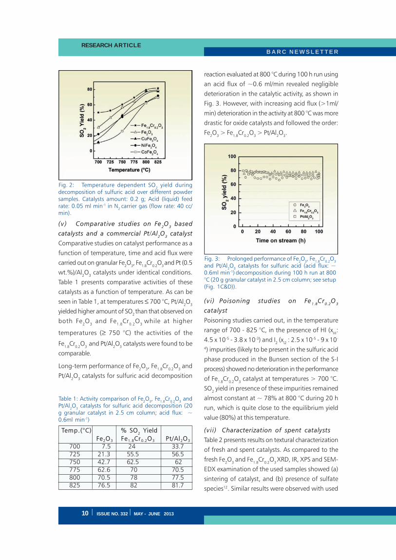
Among iron oxide based catalysts (Fe2O
3,
Fe1.8
Cr0.2
O3) and ferrites (CuFe
2O
4, CoFe
2O
4, and
NiFe2O
4), the former exhibited higher activity for
sulfuric acid decomposition reaction (Fig. 2) and
hence subjected to detailed investigations and
comparison with a commercial Pt/Al2O
3 catalyst for
their possible deployment (in granular form) in an
integrated glass setup of S-I process at CTD.
Fig. 1: Sulfuric acid decomposition setups: (A) For powder catalyst, (C) For granular catalyst. (B) and (D) arethe schematics of setup (A) & (C).
B A R C N E W S L E T T E RRESEARCH ARTICLE
10 I ISSUE NO. 332 I MAY - JUNE 2013
( v ) Comparative studies on Fe2O
3 based
catalysts and a commercial Pt/Al2O
3 catalyst
Comparative studies on catalyst performance as a
function of temperature, time and acid flux were
carried out on granular Fe2O
3, Fe
1.8Cr
0.2O
3 and Pt (0.5
wt.%)/Al2O
3 catalysts under identical conditions.
Table 1 presents comparative activities of these
catalysts as a function of temperature. As can be
seen in Table 1, at temperatures ≤ 700 °C, Pt/Al2O
3
yielded higher amount of SO2 than that observed on
both Fe2O
3 and Fe
1.8Cr
0.2O
3 while at higher
temperatures (≥ 750 °C) the activities of the
Fe1.8
Cr0.2
O3 and Pt/Al
2O
3 catalysts were found to be
comparable.
Long-term performance of Fe2O
3, Fe
1.8Cr
0.2O
3 and
Pt/Al2O
3 catalysts for sulfuric acid decomposition
reaction evaluated at 800 °C during 100 h run using
an acid flux of ~0.6 ml/min revealed negligible
deterioration in the catalytic activity, as shown in
Fig. 3. However, with increasing acid flux (>1ml/
min) deterioration in the activity at 800 °C was more
drastic for oxide catalysts and followed the order:
Fe2O
3 > Fe
1.8Cr
0.2O
3 > Pt/Al
2O
3.
( v i ) Poisoning studies on Fe1.8
Cr0.2
O3
catalyst
Poisoning studies carried out, in the temperature
range of 700 - 825 °C, in the presence of HI (xHI:
4.5 x 10⁻⁵ - 3.8 x 10⁻³) and I2 (x
I2 : 2.5 x 10⁻⁵ - 9 x 10-
4) impurities (likely to be present in the sulfuric acid
phase produced in the Bunsen section of the S-I
process) showed no deterioration in the performance
of Fe1.8
Cr0.2
O3 catalyst at temperatures > 700 °C.
SO2 yield in presence of these impurities remained
almost constant at ~ 78% at 800 °C during 20 h
run, which is quite close to the equilibrium yield
value (80%) at this temperature.
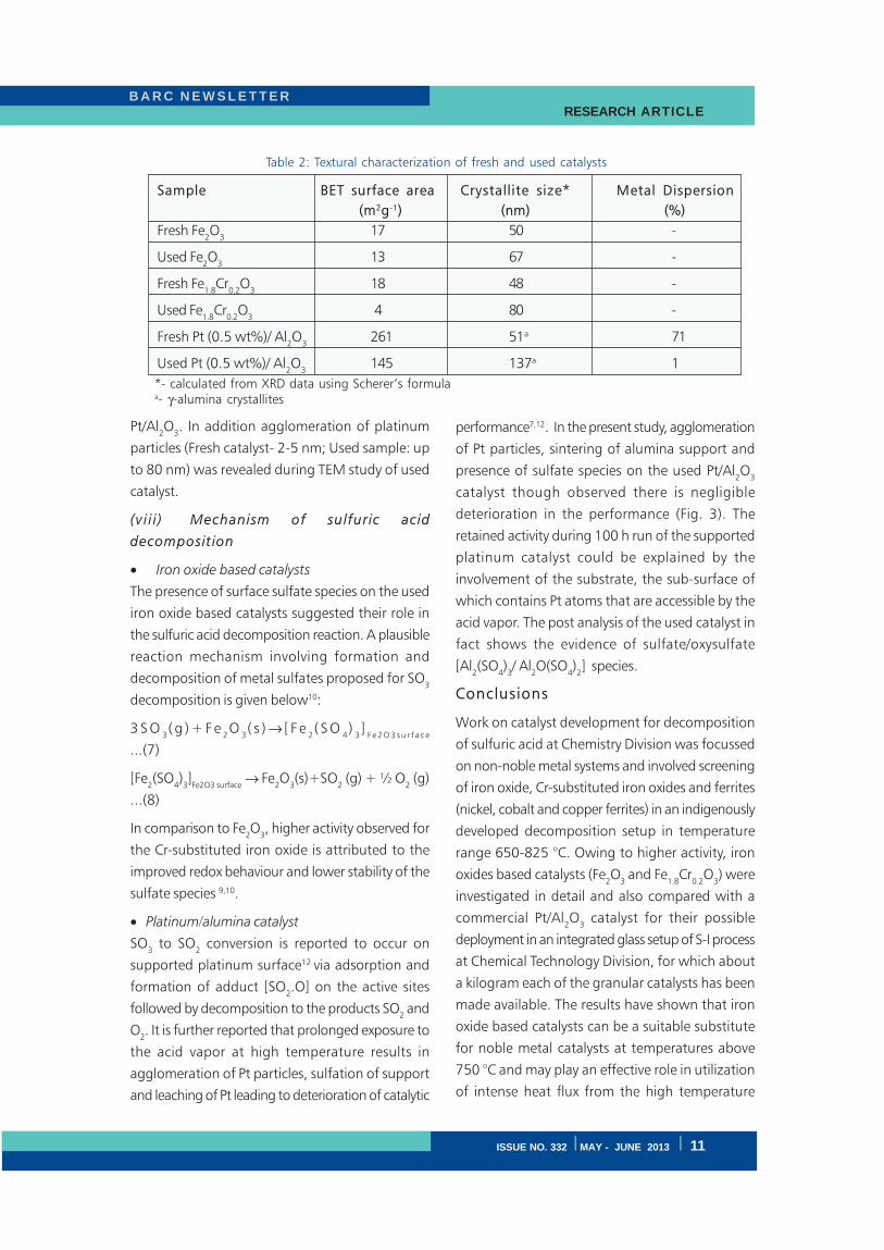
(v i i ) Characterization of spent catalysts
Table 2 presents results on textural characterization
of fresh and spent catalysts. As compared to the
fresh Fe2O
3 and Fe
1.8Cr
0.2O
3 XRD, IR, XPS and SEM-
EDX examination of the used samples showed (a)
sintering of catalyst, and (b) presence of sulfate
species12. Similar results were observed with used
Fig. 2: Temperature dependent SO2 yield during
decomposition of sulfuric acid over different powdersamples. Catalysts amount: 0.2 g; Acid (liquid) feedrate: 0.05 ml min-1 in N
2 carrier gas (flow rate: 40 cc/
min).
Temp.(°C) % SO2 Yield
Fe2O3 Fe1.8Cr0.2O3 Pt/Al2O3
700 7.5 24 33.7 725 21.3 55.5 56.5 750 42.7 62.5 62 775 62.6 70 70.5 800 70.5 78 77.5 825 76.5 82 81.7
Table 1: Activity comparison of Fe2O
3, Fe
1.8Cr
0.2O
3 and
Pt/Al2O
3 catalysts for sulfuric acid decomposition (20
g granular catalyst in 2.5 cm column; acid flux: ~0.6ml min-1)
Fig. 3: Prolonged performance of Fe2O
3, Fe
1.8Cr
0.2O
3
and Pt/Al2O
3 catalysts for sulfuric acid (acid flux: ~
0.6ml min-1) decomposition during 100 h run at 800°C (20 g granular catalyst in 2.5 cm column; see setup(Fig. 1C&D)).
B A R C N E W S L E T T E R RESEARCH ARTICLE
ISSUE NO. 332 I MAY - JUNE 2013 I 11
Pt/Al2O
3. In addition agglomeration of platinum
particles (Fresh catalyst- 2-5 nm; Used sample: up
to 80 nm) was revealed during TEM study of used
catalyst.
(v i i i ) Mechanism of sulfuric acid
decomposition
• Iron oxide based catalysts
The presence of surface sulfate species on the used
iron oxide based catalysts suggested their role in
the sulfuric acid decomposition reaction. A plausible
reaction mechanism involving formation and
decomposition of metal sulfates proposed for SO3
decomposition is given below10:
3 S O3( g ) + F e
2O
3( s ) → [ F e
2( S O
4)
3]
F e 2 O 3 s u r f a c e
...(7)
[Fe2(SO
4)3]Fe2O3 surface
→ Fe2O
3(s)+SO
2 (g) + ½ O
2 (g)
...(8)
In comparison to Fe2O
3, higher activity observed for
the Cr-substituted iron oxide is attributed to the
improved redox behaviour and lower stability of the
sulfate species 9,10.
• Platinum/alumina catalyst
SO3 to SO
2 conversion is reported to occur on
supported platinum surface12 via adsorption and
formation of adduct [SO2.O] on the active sites
followed by decomposition to the products SO2 and
O2. It is further reported that prolonged exposure to
the acid vapor at high temperature results in
agglomeration of Pt particles, sulfation of support
and leaching of Pt leading to deterioration of catalytic
performance7,12. In the present study, agglomeration
of Pt particles, sintering of alumina support and
presence of sulfate species on the used Pt/Al2O
3
catalyst though observed there is negligible
deterioration in the performance (Fig. 3). The
retained activity during 100 h run of the supported
platinum catalyst could be explained by the
involvement of the substrate, the sub-surface of
which contains Pt atoms that are accessible by the
acid vapor. The post analysis of the used catalyst in
fact shows the evidence of sulfate/oxysulfate
[Al2(SO
4)3/ Al
2O(SO
4)2] species.
Conclusions
Work on catalyst development for decomposition
of sulfuric acid at Chemistry Division was focussed
on non-noble metal systems and involved screening
of iron oxide, Cr-substituted iron oxides and ferrites
(nickel, cobalt and copper ferrites) in an indigenously
developed decomposition setup in temperature
range 650-825 °C. Owing to higher activity, iron
oxides based catalysts (Fe2O
3 and Fe
1.8Cr
0.2O
3) were
investigated in detail and also compared with a
commercial Pt/Al2O
3 catalyst for their possible
deployment in an integrated glass setup of S-I process
at Chemical Technology Division, for which about
a kilogram each of the granular catalysts has been
made available. The results have shown that iron
oxide based catalysts can be a suitable substitute
for noble metal catalysts at temperatures above
750 °C and may play an effective role in utilization
of intense heat flux from the high temperature
Sample BET surface area Crystallite size* Metal Dispersion
(m2g-1) (nm) (%)
Fresh Fe2O
317 50 -
Used Fe2O
313 67 -
Fresh Fe1.8
Cr0.2
O3
18 48 -
Used Fe1.8
Cr0.2
O3
4 80 -
Fresh Pt (0.5 wt%)/ Al2O
3261 51a 71
Used Pt (0.5 wt%)/ Al2O
3145 137a 1
Table 2: Textural characterization of fresh and used catalysts
*- calculated from XRD data using Scherer’s formulaa- γ-alumina crystallites
B A R C N E W S L E T T E RRESEARCH ARTICLE
12 I ISSUE NO. 332 I MAY - JUNE 2013
nuclear reactor for decomposition of sulfuric acid
towards realization of the goal of S-I process for
large scale hydrogen generation.
Acknowledgement
Authors are grateful to Dr. T. Mukherjee, Former
Director, Chemistry Group, and Shri C.S.R. Prasad,
Ex-Head, Chemical Technology Division, for their
keen interest and constant encouragement during
the course of this work. Help received from Ms.
Archana P. Gaikwad during analysis of sulphuric acid
decomposition products, Dr. R. Tewari, MSD, for
TEM analysis of Pt/Al2O
3 catalyst and Shri S. Kolay,
ChD, for EGA of the used samples is gratefully
acknowledged. Authors are also grateful to Shri
Ganesh S. Mane, ChD, Shri A.S. Kerkar, Ex-colleague,
ChD, and members of the Division Workshop for
their help during fabrication of decomposition setup.
References
1. Rosen A. M. “Advances in hydrogen production
by thermochemical water decomposition: a
review” Energy 35 (2010): 1068–1076.
2. Funk J. E., “Thermochemical hydrogen
production: past and present” Int. J. Hydrogen
Energy 26 (2001): 185-190.
3. Onuki K., Kubo S., Terada A., Sakaba N. and
Hino R. “Thermochemical water-splitting cycle
using iodine and sulphur” Energy Environ. Sci.,
2 (2009): 491–497.
4. Huang C, T-Raissi A. Analysis of sulfur–iodine
thermochemical cycle for solar hydrogen
production. Part I: decomposition of sulfuric
acid. Solar Energy 78 (2005) 632–646.
5. O’Keefe D. R., Norman J. H. and Williamson
D. G., “Catalysis research in thermochemical
water-splitting processes” Catal. Rev. Sci. Eng.
22 (1980) 325-369.
6. Tagawa H., Endo T. “Catalytic decomposition
of sulfuric acid using metal oxides as the oxygen
generating reaction in thermochemical water
splitting process.” Int. J. Hydrogen Energy 14
(1989):14:11-17.
7. Ginosar D. M., Petkovik L. M., Glenn A.W.
and Burch K. C., “Stability of supported
platinum sulfuric acid decomposition catalysts
for use in thermochemical water splitting cycles”
Int. J. Hydrogen Energy 32 (2007): 482-488.
8. Ginosar D.M., Rollins H. W., Petkovic L.M.,
Burch K.C., and Rush M.J., “High-temperature
sulfuric acid decomposition over complex metal
oxide catalysts” Int. J. Hydrogen Energy 34
(2009): 4065-4073.
9. Banerjee A. M., Pai M. R., Bhattacharya K.,
Tripathi A. K., Kamble V. S., Bharadwaj S. R.
and Kulshreshtha S. K., “Catalytic decomposition
of sulfuric acid on mixed Cr/Fe oxide samples
and its application in sulphur iodine cycle for
hydrogen production” Int. J. Hydrogen Energy
33 (2008): 319-326.
10. Banerjee A. M., Shirole A. R., Pai M. R., Tripathi
A. K., Bharadwaj S. R., Das D. and Sinha P. K.,
“Catalytic Activities of Fe2O
3 and Chromium
Doped Fe2O
3 for Sulfuric Acid Decomposition
Reaction in an Integrated Boiler, Preheater and
Catalytic Decomposer” Applied Catalysis B:
Environmental 127 (2012): 36– 46.
11. Banerjee A. M., Pai M. R., Meena S. S., Tripathi
A. K. and Bharadwaj S. R., “Catalytic activities
of cobalt, nickel and copper ferrospinels for
sulfuric acid decomposition: The high
temperature step in the sulfur based
thermochemical water splitting cycles” Int. J.
Hydrogen Energy 36 (2011): 4768-4780.
12. Golodates G. I. “The oxidation of sulfur-
containing inorganic compounds” Chapt.XII,
Heterogeneous catalytic reactions involving
molecular oxygen, Studies in Surface Science
and Catalysis 15 (1983): 365-387.
B A R C N E W S L E T T E R TECHNOLOGY DEVELOPMENT ARTICLE
ISSUE NO. 332 I MAY - JUNE 2013 I 13
Engineering Scale Demonstration Facility forActinide Partitioning of High Level Waste
Smitha Manohar, V.P. Patel, U.Dani, M.R.Venugopal and P.K. WattalProcess Development Division
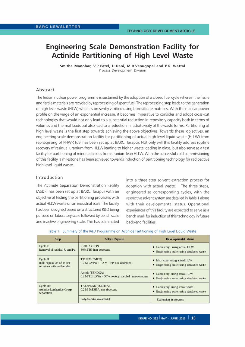
Abstract
The Indian nuclear power programme is sustained by the adoption of a closed fuel cycle wherein the fissile
and fertile materials are recycled by reprocessing of spent fuel. The reprocessing step leads to the generation
of high level waste (HLW) which is presently vitrified using borosilicate matrices. With the nuclear power
profile on the verge of an exponential increase, it becomes imperative to consider and adopt cross-cut
technologies that would not only lead to a substantial reduction in repository capacity both in terms of
volumes and thermal loads but also lead to a reduction in radiotoxicity of the waste forms. Partitioning of
high level waste is the first step towards achieving the above objectives. Towards these objectives, an
engineering scale demonstration facility for partitioning of actual high level liquid waste (HLLW) from
reprocessing of PHWR fuel has been set up at BARC, Tarapur. Not only will this facility address routine
recovery of residual uranium from HLLW leading to higher waste loading in glass, but also serve as a test
facility for partitioning of minor actinides from uranium lean HLLW. With the successful cold commissioning
of this facility, a milestone has been achieved towards induction of partitioning technology for radioactive
high level liquid waste.
Introduction
The Actinide Separation Demonstration Facility
(ASDF) has been set up at BARC, Tarapur with an
objective of testing the partitioning processes with
actual HLLW waste on an industrial scale. The facility
has been designed based on a structured R&D being
pursued on laboratory scale followed by bench scale
and inactive engineering scale. This has culminated
into a three step solvent extraction process for
adoption with actual waste. The three steps,
engineered as corresponding cycles, with the
respective solvent system are detailed in Table 1 along
with their developmental status. Operational
experiences of this facility are expected to serve as a
bench mark for induction of this technology in future
back-end facilities.
Step Solvent System Developmental status
Cycle I: Removal of residual U and Pu
PUREX (TBP) 30% TBP in n-dodecane
• Laboratory : using actual HLW • Engineering scale: using simulated waste
Cycle II: Bulk Separation of minor actinides with lanthanides
TRUEX (CMPO) 0.2 M CMPO + 1.2 M TBP in n-dodecane
• laboratory :using actual HLW • Engineering scale: using simulated waste
Amide (TEHDGA) 0.2 M TEHDGA + 30% isodecyl alcohol in n-dodecane
• Laboratory: using actual HLW • Engineering scale: using simulated waste
Cycle III: Actinide Lanthanide Group Separation
TALSPEAK (D2EHPA) 0.2 M D2EHPA in n-dodecane
• Laboratory: using actual waste • Engineering scale: using simulated waste
Polydendate(aza-amide) Evaluation in progress
Table 1: Summary of the R&D Programme on Actinide Partitioning of High Level Liquid Waste
B A R C N E W S L E T T E RTECHNOLOGY DEVELOPMENT ARTICLE
14 I ISSUE NO. 332 I MAY - JUNE 2013
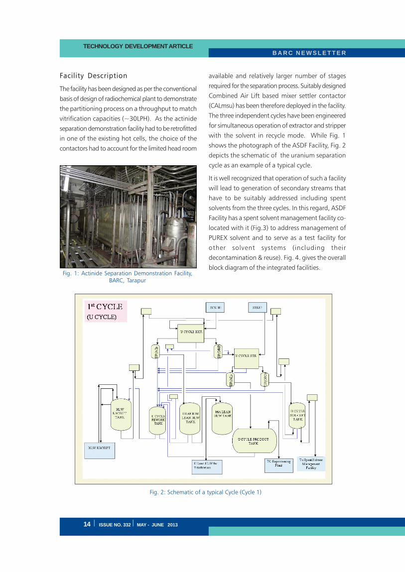
Facility Description
The facility has been designed as per the conventional
basis of design of radiochemical plant to demonstrate
the partitioning process on a throughput to match
vitrification capacities (~30LPH). As the actinide
separation demonstration facility had to be retrofitted
in one of the existing hot cells, the choice of the
contactors had to account for the limited head room
available and relatively larger number of stages
required for the separation process. Suitably designed
Combined Air Lift based mixer settler contactor
(CALmsu) has been therefore deployed in the facility.
The three independent cycles have been engineered
for simultaneous operation of extractor and stripper
with the solvent in recycle mode. While Fig. 1
shows the photograph of the ASDF Facility, Fig. 2
depicts the schematic of the uranium separation
cycle as an example of a typical cycle.
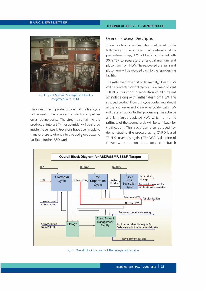
It is well recognized that operation of such a facility
will lead to generation of secondary streams that
have to be suitably addressed including spent
solvents from the three cycles. In this regard, ASDF
Facility has a spent solvent management facility co-
located with it (Fig.3) to address management of
PUREX solvent and to serve as a test facility for
other solvent systems (including their
decontamination & reuse). Fig. 4. gives the overall
block diagram of the integrated facilities.Fig. 1: Actinide Separation Demonstration Facility,
BARC, Tarapur
Fig. 2: Schematic of a typical Cycle (Cycle 1)
B A R C N E W S L E T T E R TECHNOLOGY DEVELOPMENT ARTICLE
ISSUE NO. 332 I MAY - JUNE 2013 I 15
The uranium rich product stream of the first cycle
will be sent to the reprocessing plants via pipelines
on a routine basis. The streams containing the
product of interest (Minor actinide) will be stored
inside the cell itself. Provisions have been made to
transfer these solutions into shielded glove boxes to
facilitate further R&D work.
Overall Process Description
The active facility has been designed based on the
following process developed in-house. As a
pretreatment step, HLW will be first contacted with
30% TBP to separate the residual uranium and
plutonium from HLW. The recovered uranium and
plutonium will be recycled back to the reprocessing
facility.
The raffinate of the first cycle, namely, U lean HLW
will be contacted with diglycol amide based solvent
THEDGA, resulting in separation of all trivalent
actinides along with lanthanides from HLW. The
stripped product from this cycle containing almost
all the lanthanides and actinides associated with HLW
will be taken up for further processing. The actinide
and lanthanide depleted HLW which forms the
raffinate of the second cycle will be sent back for
vitrification. This cycle can also be used for
demonstrating the process using CMPO based
TRUEX solvent as against TEHDGA. Validation of
these two steps on laboratory scale batch
Fig. 3: Spent Solvent Management Facilityintegrated with ASDF
Fig. 4: Overall Block diagram of the integrated facilities
B A R C N E W S L E T T E RTECHNOLOGY DEVELOPMENT ARTICLE
16 I ISSUE NO. 332 I MAY - JUNE 2013
equilibration tests with actual high level waste
from reprocessing of short cooled fuel is given in
Table 2. The decrease in βγ activity observed on
contact with TEHDGA solvent was mainly on
account of co-extraction of the rare earths elements
along with minor actinides. Strontium and
ruthenium were some of the other fission products
extracted to a smaller extent.
Table 2: Process Validation with actual HLW (laboratorystudies) (100 times dilution of HLLW)Cycle I30% TBP in dodecane :Phase ratio (A/O) 2:1 (2 contacts)Cycle II0.2 M TEHDGA + 30% isodecyl alcohol :Phase Ratio(A/O) : 3:1 (3 contacts)
in n-dodecane
The stripped product of the second cycle rich in
minor actinides & lanthanides will form the feed for
the third cycle. The present flow sheet has been
developed based on laboratory experiments carried
out, the results of which are given in Table 3. In
view of the challenges that An-Ln separation pose,
provisions have also been made to test processes
that would develop in the future, by integrating
shielded glove boxes to the facility.
Cold Commissioning of the Facility
As a part of cold commissioning activities all the
three cycles have been tested with inactive
surrogates to assess the overall performance of the
three cycles. These runs were undertaken to establish
the hydraulic/mass transfer performance of these
cycles along with the instrumentation parameters.
All the operations were carried out from the control
room as per the design intent. Besides, these runs
also established the operating procedures as
envisaged during design. Fig. 5 gives the live control
room indications especially with regard to mixer-
settlers and its allied metering.
While nitric acid served as surrogate for the first
cycle, inactive rare earths in overall concentration
as found in concentrated HLW were used as
surrogates in the second cycle. Group separation of
actinides from the co-extracted lanthanides has been
successfully simulated using TALSPEAK based
process with neodymium as marker. All the three
cycles were tested with about ~ 1000 lts of aqueous
feed and the respective solvents in closed loop as
envisaged during actual operations.
Solvent Distribution rat io
Am3+ La3+ Ce3+ Eu3+ DADA ( 0.1M in n-octanol) (aq. pH 2.5)
2.0 0.03 0.08 0.75
D2EHPA (0.2M in n-dodecane) (aq. pH 2.5, containing 0.05 M DTPA & 1.0 M Lact ic acid )
0.08 36 6.7 4.2
Table 3: Comparative data on trivalent An-Ln groupseparation
Fig. 5: Remote operations of the extraction cycles from control room
Solution U (g/L) Gross α (Bq/mL)
Feed (HLLW) 10.9 217100 Raffinate (TBP) 0.05 215000
Raffinate (TEHDGA) ND ND
B A R C N E W S L E T T E R TECHNOLOGY DEVELOPMENT ARTICLE
ISSUE NO. 332 I MAY - JUNE 2013 I 17
( i ) Process Performance for residual
uranium separation (Cycle I)
Continuous operation of the first cycle with 4 M
nitric acid, 30% TBP as the extractant and water as
the strippant yielded acid pick up in tune with those
predicted by computer code SEPHIS. These results
have established satisfactory performance of the first
cycle. These runs were followed up with simulated
waste containing natural uranium and other rare
earth nitrates. Table 4 gives the summarised results
of this run.
Table 4: Summarized cold commissioning results:
Cycle I
Solvent system : 30% TBP in n-dodecane.
Aqueous feed : 4 M Nitric Acid with naturaluranium and RE nitrates
Strip solution : Water
Flow rates A/O/S : 35/13/14 (LPH); Solution
processed 1600 lts
( i i ) Process Performance for Bulk
separation of trivalent actinides &
lanthanides (cycle II)
For the purpose of testing the second cycle, about
800 lts. of feed solution was prepared with the rare
earth composition as given in Table 5. Start up
conditions was initially established with 4 M nitric
acid solution in extractor and DM water in stripper.
After stabilizing the complete loop with solvent,
rare earth containing solution was fed into the
extractor and DTPA containing strippant was fed to
the stripper. Density/interphase indications in the
various feed and raffinate density pots served to
assess the process. The online density readings were
in conformity to laboratory results ascertaining the
design basis of the facility.
Exit aqueous samples were collected and analyzed
for the rare earth concentration by ICP-AES. Typical
results after attaining steady state is given in
Table 5. The results indicate an extraction & stripping
efficiency of >99.9%. These runs have established
satisfactory working of the second cycle
Table 5: Summarized cold commissioning results:Cycle II
Solvent system : 0.2 M TEHDGA + 30% isodecylalcohol in n-dodecane.
Aqueous feed : ~ 1890 mg/L of rare earths in4 M nitric acid
Flow rates A/O/S : 36/18/18 (LPH) ; Solution
Processed : 800 lts
( i i i ) Process Performance for Separation of
actinides from lanthanides (cycle III)
The product from the second cycle amounting to
about 450 lts was diluted with virgin DTPA-lactic
acid solution and the overall pH was adjusted to
2.6 by addition of NaOH solution. The total volume
of the feed thus constituted was 1000 Liters. In the
pH region that the cycle is to be operated, it is
expected that the trivalent actinide will be
preferentially complexed by DTPA and hence will
have very low extractability in the D2EHPA solvent.
Among the rare earths, Neodymium has been
observed to have the lowest distribution co efficient
in this pH range and hence served as a marker during
these engineering trials. Subsequently, the extractor
and stripper were stabilized with feed solution for
extractor and 2 M nitric acid in stripper. Density/
interphase indications in the various feed and
raffinate density pots served to assess the process
as in the previous cycles. Exit aqueous samples were
collected and analysed for the rare earth
concentration by ICP-AES. A typical result after
attaining steady state is given Table 6. While
lanthanum was completely extracted, a small amount
of neodymium was left behind (served as a marker
for americium). Near total stripping was established
Sr. No Stream Acidity (M) Uranium (mg/L)
1 Feed 4.0 7140 2 Raffinate 3.7 3-10
5 Stripped prod. 0.8 17850
Stream Ce (mg/L)
La (mg/L)
Nd (mg/L)
Pr (mg/L)
Sm (mg/L)
Y (mg/L)
Feed 785 511 422 113 58 7.4
Raffinate 0.052 0.032 0.034 <0.2 <0.1 <0.1
Stripped Product
1622 1027 827 223 108 12.2
B A R C N E W S L E T T E RTECHNOLOGY DEVELOPMENT ARTICLE
18 I ISSUE NO. 332 I MAY - JUNE 2013
during the operation. No pH drift was observed at
the exit of the extractor, obviating any need for pH
adjustment within the system. These results have
established satisfactory performance of the third
cycle.
( i v ) Integrated testing of the three cycles
with natural uranium
This trial was carried out to test the process
performance of the three cycles in a manner similar
to actual operating conditions with simulated waste
solutions. The simulated feed comprised of 4 M
nitric acid with 7.14 g/L of uranium and ~ 1500
mg/L of rare earth nitrates along with appropriate
quantities of strontium and molybdenum. While
cycles I & II were operated continuously in tandem,
the third cycle (cycle III) was operated independently
after adjustment of pH as per the design intent.
These runs were undertaken at a throughput of about
35 LPH (simulated waste) and the runs spanned
~45 hrs of continuous operations. The terminal
densities from control room indications were in
accordance with measured values. The interface in
all the extractors and strippers could be detected
and maintained as required. Periodic samples were
collected and analyzed by ICP-AES. Overall results
indicate separation efficiency of > 99.8% for
uranium and rare earths. Based on these successful
trials the facility is presently being prepared for warm
commissioning.
Acknowledgements
This work detailed out is a consolidation of efforts
undertaken in Nuclear Recycle Group and Solvent
Development Section of Materials Group. Working
as a team member, the contribution of
Shri.J.N.Sharma,SO/G,MPD in the synthesis and
development of novel solvents is noteworthy.
Acknowledgements are due to FRD laboratories
where the lab. studies & analysis work have been
carried out. The support of the Nuclear Recycle
Board in erection, installation & commissioning of
the facility is deeply acknowledged.
Stream Ce (mg/L)
La (mg/L)
Nd (mg/L)
Pr (mg/L)
Sm (mg/L)
Y (mg/L)
Am241 (cps)
Feed* 521.8
(357)
343.4
(116)
273.8
(226)
75.96
(20.6)
34.72
(153)
3.97 nil (31.12)
Raffinate* 2.21 (0.94)
0.07 (ND)
10.13 (10.3)
0.57 (0.22)
2.86 (5.52)
<0.1 nil (29.26)
Stripped Product
1562 1033 731.6 222.6 93.72 8.90 nil
Table 6: Summarized cold commissioning results: Cycle III
Solvent system : 0.2 M D2EHPA in n-dodecane.
Aqueous feed : 0.05 M DTPA + 1 M Lactic acid solution (stripped product of thesecond cycle with pH adjusted to 2.6 and diluted with respect torare earths)
Strip solution : 2 M HNO3
Flow Rates A/O/S : 45/30/15 (LPH); Solution Processed: 1000 L
*The quantities in parenthesis are the values obtained during Am 241 spiked lab scale mixer settler
trials, where Am losses to the loaded organic was observed to be < 6 %
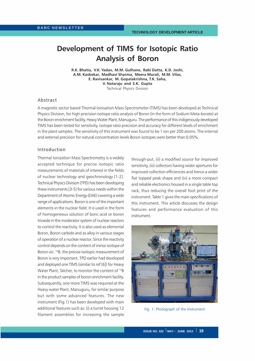
B A R C N E W S L E T T E R TECHNOLOGY DEVELOPMENT ARTICLE
ISSUE NO. 332 I MAY - JUNE 2013 I 19
Development of TIMS for Isotopic Ratio
Analysis of Boron
R.K. Bhatia, V.K. Yadav, M.M. Gulhane, Rabi Datta, K.D. Joshi,A.M. Kasbekar, Madhavi Sharma, Meera Murali, M.M. Vilas,
E. Ravisankar, M. Gopalakrishna, T.K. Saha,V. Nataraju and S.K. Gupta
Technical Physics Division
Abstract
A magnetic sector based Thermal Ionisation Mass Spectrometer (TIMS) has been developed at Technical
Physics Division, for high precision isotope ratio analysis of Boron (in the form of Sodium Meta-borate) at
the Boron enrichment facility, Heavy Water Plant, Manuguru. The performance of this indigenously developed
TIMS has been tested for sensitivity, isotope ratio precision and accuracy for different levels of enrichment
in the plant samples. The sensitivity of this instrument was found to be 1 ion per 200 atoms. The internal
and external precision for natural concentration levels Boron isotopes were better than 0.05%.
Introduction
Thermal Ionization Mass Spectrometry is a widely
accepted technique for precise isotopic ratio
measurements of materials of interest in the fields
of nuclear technology and geochronology [1-2].
Technical Physics Division (TPD) has been developing
these instruments [3-5] for various needs within the
Department of Atomic Energy (DAE) covering a wide
range of applications. Boron is one of the important
elements in the nuclear field. It is used in the form
of homogeneous solution of boric acid or boron
trioxide in the moderator system of nuclear reactors
to control the reactivity. It is also used as elemental
Boron, Boron carbide and as alloy in various stages
of operation of a nuclear reactor. Since the reactivity
control depends on the content of minor isotope of
Boron viz. 10B, the precise isotopic measurement of
Boron is very important. TPD earlier had developed
and deployed one TIMS (similar to ref [6]) for Heavy
Water Plant, Talcher, to monitor the content of 10B
in the product samples of boron enrichment facility.
Subsequently, one more TIMS was required at the
Heavy water Plant, Manuguru, for similar purpose
but with some advanced features. The new
instrument (Fig.1) has been developed with main
additional features such as: (i) a turret housing 12
filament assemblies for increasing the sample
through-put, (ii) a modified source for improved
sensitivity, (iii) collectors having wider apertures for
improved collection efficiencies and hence a wider
flat topped peak shape and (iv) a more compact
and reliable electronics housed in a single table top
rack, thus reducing the overall foot print of the
instrument. Table 1 gives the main specifications of
this instrument. This article discusses the design
features and performance evaluation of this
instrument.
Fig. 1: Photograph of the Instrument
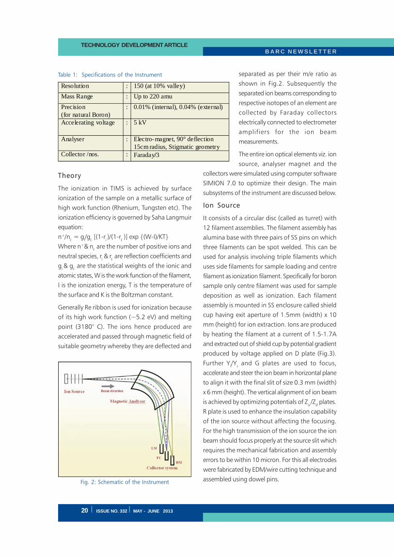
B A R C N E W S L E T T E RTECHNOLOGY DEVELOPMENT ARTICLE
20 I ISSUE NO. 332 I MAY - JUNE 2013
Theory
The ionization in TIMS is achieved by surface
ionization of the sample on a metallic surface of
high work function (Rhenium, Tungsten etc). The
ionization efficiency is governed by Saha Langmuir
equation:
n+/nï = g
i/g
ï [(1-r
i )/(1-r
ï )] exp {(W-I)/KT}
Where n+& nï are the number of positive ions and
neutral species, ri & r
ï are reflection coefficients and
gi & g
ï are the statistical weights of the ionic and
atomic states, W is the work function of the filament,
I is the ionization energy, T is the temperature of
the surface and K is the Boltzman constant.
Generally Re ribbon is used for ionization because
of its high work function (~5.2 eV) and melting
point (3180° C). The ions hence produced are
accelerated and passed through magnetic field of
suitable geometry whereby they are deflected and
separated as per their m/e ratio as
shown in Fig.2. Subsequently the
separated ion beams corresponding to
respective isotopes of an element are
collected by Faraday collectors
electrically connected to electrometer
amplifiers for the ion beam
measurements.
The entire ion optical elements viz. ion
source, analyser magnet and the
collectors were simulated using computer software
SIMION 7.0 to optimize their design. The main
subsystems of the instrument are discussed below.
Ion Source
It consists of a circular disc (called as turret) with
12 filament assemblies. The filament assembly has
alumina base with three pairs of SS pins on which
three filaments can be spot welded. This can be
used for analysis involving triple filaments which
uses side filaments for sample loading and centre
filament as ionization filament. Specifically for boron
sample only centre filament was used for sample
deposition as well as ionization. Each filament
assembly is mounted in SS enclosure called shield
cup having exit aperture of 1.5mm (width) x 10
mm (height) for ion extraction. Ions are produced
by heating the filament at a current of 1.5-1.7A
and extracted out of shield cup by potential gradient
produced by voltage applied on D plate (Fig.3).
Further Yl/Y
r and G plates are used to focus,
accelerate and steer the ion beam in horizontal plane
to align it with the final slit of size 0.3 mm (width)
x 6 mm (height). The vertical alignment of ion beam
is achieved by optimizing potentials of Zu /Z
d plates.
R plate is used to enhance the insulation capability
of the ion source without affecting the focusing.
For the high transmission of the ion source the ion
beam should focus properly at the source slit which
requires the mechanical fabrication and assembly
errors to be within 10 micron. For this all electrodes
were fabricated by EDM/wire cutting technique and
assembled using dowel pins.
Resolution : 150 (at 10% valley)
Mass Range : Up to 220 amu
Precision
(for natural Boron)
: 0.01% (internal), 0.04% (external)
Accelerating voltage : 5 kV
Analyser : Electro-magnet, 90° deflection
15cm radius, Stigmatic geometry Collector /nos. : Faraday/3
Table 1: Specifications of the Instrument
Fig. 2: Schematic of the Instrument
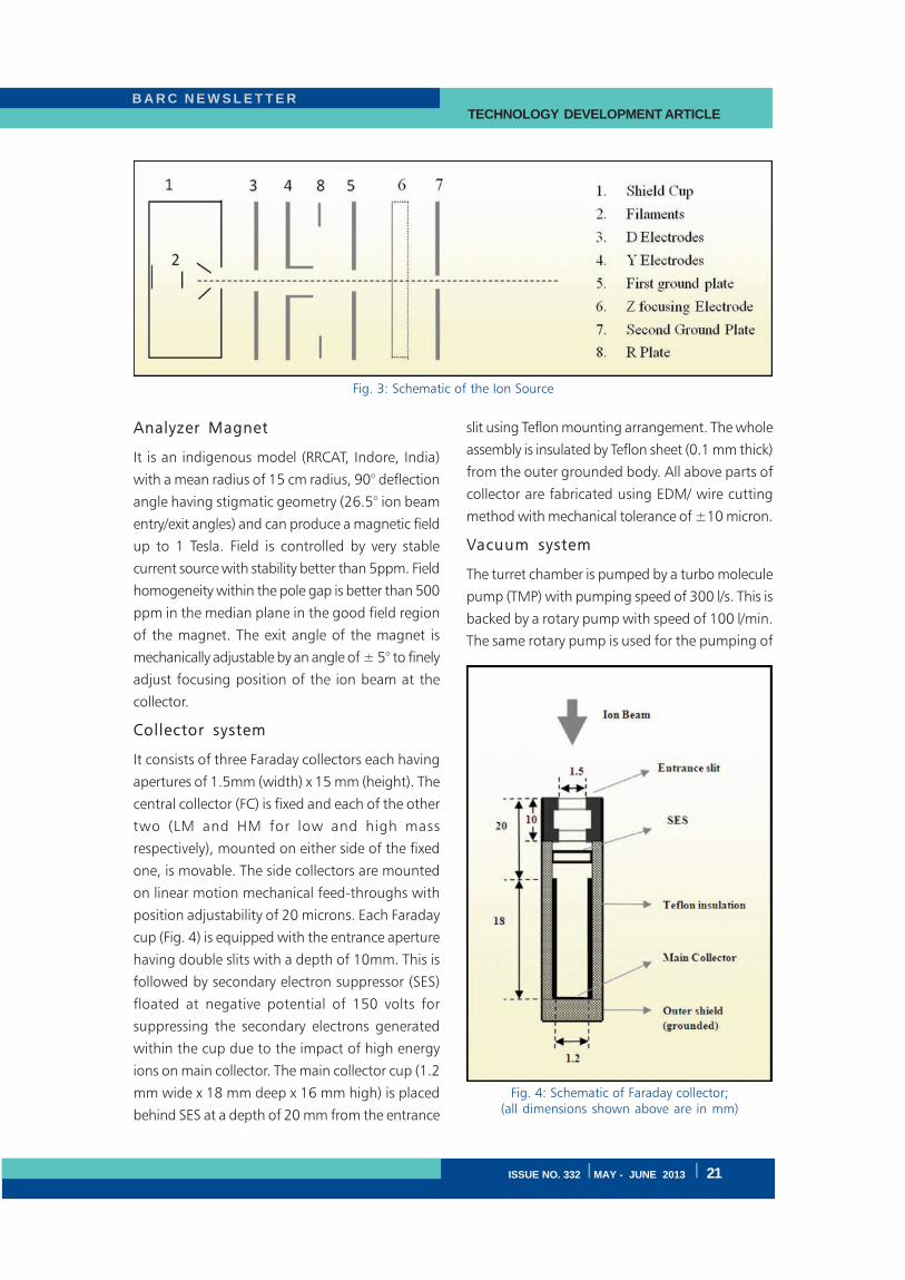
B A R C N E W S L E T T E R TECHNOLOGY DEVELOPMENT ARTICLE
ISSUE NO. 332 I MAY - JUNE 2013 I 21
Analyzer Magnet
It is an indigenous model (RRCAT, Indore, India)
with a mean radius of 15 cm radius, 90° deflection
angle having stigmatic geometry (26.5° ion beam
entry/exit angles) and can produce a magnetic field
up to 1 Tesla. Field is controlled by very stable
current source with stability better than 5ppm. Field
homogeneity within the pole gap is better than 500
ppm in the median plane in the good field region
of the magnet. The exit angle of the magnet is
mechanically adjustable by an angle of ± 5° to finely
adjust focusing position of the ion beam at the
collector.
Collector system
It consists of three Faraday collectors each having
apertures of 1.5mm (width) x 15 mm (height). The
central collector (FC) is fixed and each of the other
two (LM and HM for low and high mass
respectively), mounted on either side of the fixed
one, is movable. The side collectors are mounted
on linear motion mechanical feed-throughs with
position adjustability of 20 microns. Each Faraday
cup (Fig. 4) is equipped with the entrance aperture
having double slits with a depth of 10mm. This is
followed by secondary electron suppressor (SES)
floated at negative potential of 150 volts for
suppressing the secondary electrons generated
within the cup due to the impact of high energy
ions on main collector. The main collector cup (1.2
mm wide x 18 mm deep x 16 mm high) is placed
behind SES at a depth of 20 mm from the entrance
slit using Teflon mounting arrangement. The whole
assembly is insulated by Teflon sheet (0.1 mm thick)
from the outer grounded body. All above parts of
collector are fabricated using EDM/ wire cutting
method with mechanical tolerance of ±10 micron.
Vacuum system
The turret chamber is pumped by a turbo molecule
pump (TMP) with pumping speed of 300 l/s. This is
backed by a rotary pump with speed of 100 l/min.
The same rotary pump is used for the pumping of
Fig. 3: Schematic of the Ion Source
Fig. 4: Schematic of Faraday collector;(all dimensions shown above are in mm)
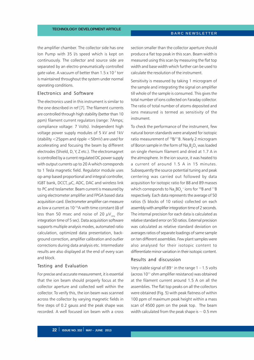
B A R C N E W S L E T T E RTECHNOLOGY DEVELOPMENT ARTICLE
22 I ISSUE NO. 332 I MAY - JUNE 2013
the amplifier chamber. The collector side has one
Ion Pump with 35 l/s speed which is kept on
continuously. The collector and source side are
separated by an electro-pneumatically controlled
gate valve. A vacuum of better than 1.5 x 10⁻⁷ torr
is maintained throughout the system under normal
operating conditions.
Electronics and Software
The electronics used in this instrument is similar to
the one described in ref [7]. The filament currents
are controlled through high stability (better than 10
ppm) filament current regulators (range: 7Amps;
compliance voltage: 7 Volts). Independent high
voltage power supply modules of 5 kV and 1kV
(stability <25ppm and ripple <50mV) are used for
accelerating and focusing the beam by different
electrodes (Shield, D, Y, Z etc.). The electromagnet
is controlled by a current regulated DC power supply
with output currents up to 20 A which corresponds
to 1 Tesla magnetic field. Regulator module uses
op-amp based proportional and integral controller,
IGBT bank, DCCT, μC, ADC, DAC and wireless link
to PC and teslameter. Beam current is measured by
using electrometer amplifier and FPGA based data
acquisition card. Electrometer amplifier can measure
as low a current as 10-15A with time constant (ô) of
less than 50 msec and noise of 20 μVrms
(for
integration time of 5 sec). Data acquisition software
supports multiple analysis modes, automated ratio
calculation, optimized data presentation, back-
ground correction, amplifier calibration and outlier
corrections during data analysis etc. Intermediate
results are also displayed at the end of every scan
and block.
Testing and Evaluation
For precise and accurate measurement, it is essential
that the ion beam should properly focus at the
collector aperture and collected well within the
collector. To verify this, the ion beam was scanned
across the collector by varying magnetic fields in
fine steps of 0.2 gauss and the peak shape was
recorded. A well focused ion beam with a cross
section smaller than the collector aperture should
produce a flat top peak in this scan. Beam width is
measured using this scan by measuring the flat top
width and base width which further can be used to
calculate the resolution of the instrument.
Sensitivity is measured by taking 1 microgram of
the sample and integrating the signal on amplifier
till whole of the sample is consumed. This gives the
total number of ions collected on Faraday collector.
The ratio of total number of atoms deposited and
ions measured is termed as sensitivity of the
instrument.
To check the performance of the instrument, few
natural boron standards were analysed for isotopic
ratio measurement of 10B/11B. Nearly 2 microgram
of Boron sample in the form of Na2B
4O
7 was loaded
on single rhenium filament and dried at 1.7 A in
the atmosphere. In the ion source, it was heated to
a current of around 1.5 A in 15 minutes.
Subsequently the source potential tuning and peak
centering was carried out followed by data
acquisition for isotopic ratio for 88 and 89 masses
which corresponds to Na2BO
2
+ ions for 10B and 11B
respectively. Each data represents the average of 50
ratios (5 blocks of 10 ratios) collected on each
assembly with amplifier integration time of 2 seconds.
The internal precision for each data is calculated as
relative standard error on 50 ratios. External precision
was calculated as relative standard deviation on
averages ratios of separate loadings of same sample
on ten different assemblies. Few plant samples were
also analysed for their isotopic content to
differentiate minor variation in their isotopic content.
Results and discussion
Very stable signal of 89+ in the range 1 – 1.5 volts
(across 1011 ohm amplifier resistance) was obtained
at the filament current around 1.5 A on all the
assemblies. The flat top peaks on all the collectors
were obtained (Fig. 5) with peak flatness of within
100 ppm of maximum peak height within a mass
scan of 4500 ppm on the peak top. The beam
width calculated from the peak shape is ~ 0.5 mm
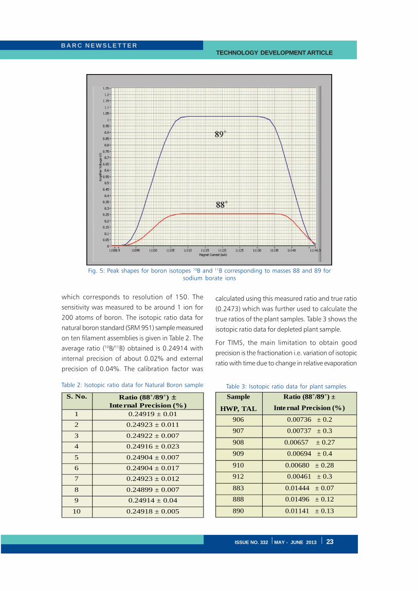
B A R C N E W S L E T T E R TECHNOLOGY DEVELOPMENT ARTICLE
ISSUE NO. 332 I MAY - JUNE 2013 I 23
which corresponds to resolution of 150. The
sensitivity was measured to be around 1 ion for
200 atoms of boron. The isotopic ratio data for
natural boron standard (SRM 951) sample measured
on ten filament assemblies is given in Table 2. The
average ratio (10B/11B) obtained is 0.24914 with
internal precision of about 0.02% and external
precision of 0.04%. The calibration factor was
calculated using this measured ratio and true ratio
(0.2473) which was further used to calculate the
true ratios of the plant samples. Table 3 shows the
isotopic ratio data for depleted plant sample.
For TIMS, the main limitation to obtain good
precision is the fractionation i.e. variation of isotopic
ratio with time due to change in relative evaporation
Fig. 5: Peak shapes for boron isotopes 10B and 11B corresponding to masses 88 and 89 forsodium borate ions
S. No.
Ratio (88+/89+) ±
Internal Precision (%)
1 0.24919 ± 0.01
2 0.24923 ± 0.011
3 0.24922 ± 0.007
4 0.24916 ± 0.023
5 0.24904 ± 0.007
6 0.24904 ± 0.017
7 0.24923 ± 0.012
8 0.24899 ± 0.007
9 0.24914 ± 0.04
10 0.24918 ± 0.005
Sample
HWP, TAL
Ratio (88+/89+) ±
Internal Precision (%)
906 0.00736 ± 0.2
907 0.00737 ± 0.3
908 0.00657 ± 0.27
909 0.00694 ± 0.4
910 0.00680 ± 0.28
912 0.00461 ± 0.3
883 0.01444 ± 0.07
888 0.01496 ± 0.12
890 0.01141 ± 0.13
Table 2: Isotopic ratio data for Natural Boron sample Table 3: Isotopic ratio data for plant samples
B A R C N E W S L E T T E RTECHNOLOGY DEVELOPMENT ARTICLE
24 I ISSUE NO. 332 I MAY - JUNE 2013
rates of isotopes with time [8]. Since in this case
only two isotopes are present, the internal
normalization is not possible. The only way to
circumvent this problem is to maintain same
conditions for every sample at every stage i.e.
sample loading, filament heating profile and data
acquisition time. During all these analysis every care
was taken to reproduce these conditions for every
sample.
Conclusion
The basic evaluation of the instrument shows that
the instrument is suitable for precise isotopic ratio
measurements for Boron with a precision of 0.02%
internal and 0.04% external. It can be used for other
masses falling in the mass range of 1-200 amu.
The sensitivity and peak shapes obtained are highly
satisfactory for the analysis of Boron samples.
Analysis time involved in measurement on one
sample is 30- 35 minutes. Moreover, the provision
of turret with 12 filament assemblies increases the
throughput of the system and makes it more useful
for the plant where the operator has to routinely
analyze more number of samples.
Acknowledgement
Authors express their gratitude to Dr. S.Kailas,
Director, Physics Group, BARC for his constant
support and encouragement throughout this
development. They also wish to acknowledge the
colleagues from TPD, who have contributed
untiringly to this development. They also wish to
thank the team at HWP, Manuguru for their
participation during the acceptance tests.
References
1. S. Richter, S.A. Goldberg, International Journal
of Mass Spectrometry 229 (2003) 181.
2. Modern isotope ratio mass spectrometry by
I.T.Platzner, John Wiley & Sons, 1997
3. Rajender K. Bhatia, Yogesh Kumar, K. Prathap
Reddy, V.K. Yadav, E. Ravisankar, T.K. Saha, V.
Nataraju, V.K. Handu, International Journal of
Mass Spectrometry 313 (2012) 36– 40
4. R.K. Bhatia, V.K. Yadav, V.M. Mahadeshwar,
M.M. Gulhane, E. Ravisankar, T.K. Saha, V.
Nataraju, S.K. Gupta, International Journal of
Mass Spectrometry 339– 340 (2013) 39– 44
5. Thermal Ionisation Mass Spectrometer for the
isotopic analysis of Lithium and Boron-
S.N.Bindal et.al., p 761, 8th ISMAS Symposium
1999.
6. Rajender K. Bhatia, R. Datta, Rekhu Chandak,
M. M. Gulhane, Pratap R. Kasina, A. M.
Kasbekar, N. Ved, M. Gopalakrishna, E.
Ravisankar, T. K. Saha, V. Nataraju, and V. K.
Handu, Proceedings of 11th ISMAS-TRICON
2009
7. Design and Development of Electronics for Dual
Source Mass Spectrometer-R. Chandak, R.
Datta, M. M. Gulhane, V. K. Handu, V. B.
Reddy and T. K. Saha-13th ISMAS Symposium
cum Workshop, 2008, BARC, Mumbai.
8. R.M. Rao, A.R. Parab, K. Sasibhushan, S.K.
Aggarwal, International Journal of Mass
Spectrometry 273 (2008) 105–110.
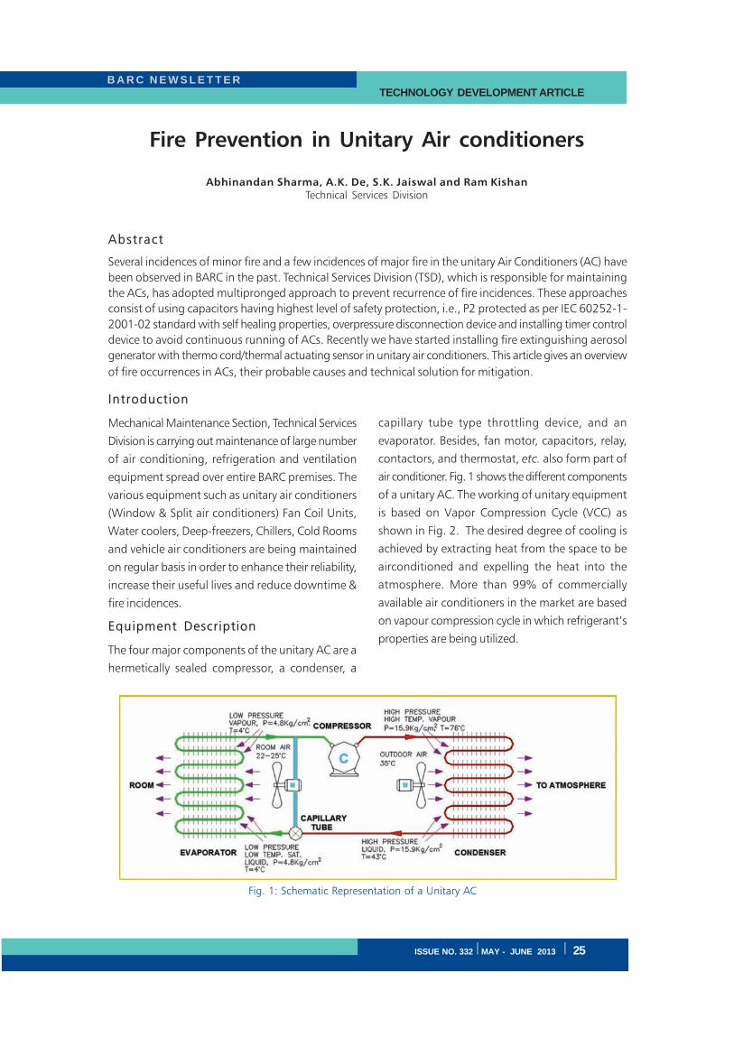
B A R C N E W S L E T T E R TECHNOLOGY DEVELOPMENT ARTICLE
ISSUE NO. 332 I MAY - JUNE 2013 I 25
Fire Prevention in Unitary Air conditioners
Abhinandan Sharma, A.K. De, S.K. Jaiswal and Ram KishanTechnical Services Division
Abstract
Several incidences of minor fire and a few incidences of major fire in the unitary Air Conditioners (AC) have
been observed in BARC in the past. Technical Services Division (TSD), which is responsible for maintaining
the ACs, has adopted multipronged approach to prevent recurrence of fire incidences. These approaches
consist of using capacitors having highest level of safety protection, i.e., P2 protected as per IEC 60252-1-
2001-02 standard with self healing properties, overpressure disconnection device and installing timer control
device to avoid continuous running of ACs. Recently we have started installing fire extinguishing aerosol
generator with thermo cord/thermal actuating sensor in unitary air conditioners. This article gives an overview
of fire occurrences in ACs, their probable causes and technical solution for mitigation.
Introduction
Mechanical Maintenance Section, Technical Services
Division is carrying out maintenance of large number
of air conditioning, refrigeration and ventilation
equipment spread over entire BARC premises. The
various equipment such as unitary air conditioners
(Window & Split air conditioners) Fan Coil Units,
Water coolers, Deep-freezers, Chillers, Cold Rooms
and vehicle air conditioners are being maintained
on regular basis in order to enhance their reliability,
increase their useful lives and reduce downtime &
fire incidences.
Equipment Description
The four major components of the unitary AC are a
hermetically sealed compressor, a condenser, a
capillary tube type throttling device, and an
evaporator. Besides, fan motor, capacitors, relay,
contactors, and thermostat, etc. also form part of
air conditioner. Fig. 1 shows the different components
of a unitary AC. The working of unitary equipment
is based on Vapor Compression Cycle (VCC) as
shown in Fig. 2. The desired degree of cooling is
achieved by extracting heat from the space to be
airconditioned and expelling the heat into the
atmosphere. More than 99% of commercially
available air conditioners in the market are based
on vapour compression cycle in which refrigerant’s
properties are being utilized.
Fig. 1: Schematic Representation of a Unitary AC
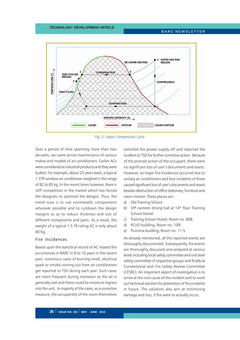
B A R C N E W S L E T T E RTECHNOLOGY DEVELOPMENT ARTICLE
26 I ISSUE NO. 332 I MAY - JUNE 2013
Over a period of time spanning more than two
decades, we came across maintenance of various
makes and models of air conditioners. Earlier ACs
were considered as industrial products and they were
bulkier. For example, about 25 years back, a typical
1.5TR window air conditioner weighed in the range
of 82 to 85 kg. In the recent times however, there is
stiff competition in the market which has forced
the designers to optimize the designs. Thus, the
trend now is to use nonmetallic components
wherever possible and to cutdown the design
margins so as to reduce thickness and size of
different components and parts. As a result, the
weight of a typical 1.5 TR rating AC is only about
60 Kg.
Fire Incidences
Based upon the statistical record of AC related fire
occurrences in BARC in 8 to 10 years in the recent
past, numerous cases of burning smell, electrical
spark or smoke coming out from air conditioners
get reported to TSD during each year. Such cases
are more frequent during monsoon as the air is
generally wet and there could be moisture ingress
into the unit. In majority of the cases, as a corrective
measure, the occupant(s) of the room themselves
switched the power supply off and reported the
incident to TSD for further corrective action. Because
of the prompt action of the occupant, there were
no significant loss of user’s documents and assets.
However, six major fire incidences occurred due to
unitary air conditioners and four incidents of these
caused significant loss of user’s documents and assets
besides destruction of office stationery, furniture and
room interior. These places are:
a) Old Training School.
b) VIP canteen dining hall at 14th floor Training
School Hostel.
c) Training School Hostel, Room no. 808.
d) RCnD building, Room no. 109.
e) Purnima building, Room no. 11-S.
As already mentioned, all the reported events are
thoroughly documented. Subsequently, the events
are thoroughly discussed and analyzed at various
levels including local safety committee and unit level
safety committee of respective groups and finally at
Conventional and Fire Safety Review Committee
(CFSRC). An important aspect of investigation is to
arrive at the root cause of the incident and to work
out technical solution for prevention of fire incidents
in future. The solutions also aim at minimizing
damage and loss, if fire were to actually occur.
Fig. 2: Vapor Compression Cycle
B A R C N E W S L E T T E R TECHNOLOGY DEVELOPMENT ARTICLE
ISSUE NO. 332 I MAY - JUNE 2013 I 27
Causes of AC Fire Incidents
Based on the analysed results and feedback of various
safety committees and experience of TSD engineers,
it can be stated that the initiation of fire in window
and split air conditioners was due to one or more of
the following factors:
Poor Workmanship of Electrical Wiring and
Loose Connection: Owing to stiff competition
in the Indian consumer market, it is suspected
though difficult to establish that the measures
enforced by manufacturers to reduce manufacturing
cost might affect the quality of components and
materials including wire, clips and joints. Also,
sometimes the workmanship could be poor, i.e.,
soldering/crimping of lugs may not be properly
done, screws might not be fitted properly leaving
loose connection, etc.
Thermostat malfunctioning: Sometimes the
thermostat does not work properly and fails to cut-
off the machine which results in continuous running
of compressor and finally may lead to fire.
Failure of capacitors: Most of the commercially
available air conditioners are provided with non-
metallic or metallic capacitor without explosion proof
features. It is observed that over a period of time,
the dielectric material of the capacitor deteriorates
whereby dielectric loss might increase. This would
cause overheating and chances of bursting increases
which ultimately may lead to fire.
Continuous running of air conditioners:
Unitary ACs are generally designed to work
intermittently, typically with duty cycle of 12 hours,
unless specifically ordered. However, due to under
estimation of heat load, too low temperature setting
of thermostat of the machine, and bad usage
practices e.g. operating ACs with doors/ windows
kept open, continuous running of ACs might
happen. As these ACs are not designed for
continuous operation beyond 12 hours, the
components may get overheated leading to bursting
and ultimately leading to initiation of fire.
Failure of transformer in control circuit
(PCB): Overheating of transformer provided in the
control circuit of air conditioner may lead to its
burning, resulting in initiation of fire.
Addition/alteration in air conditioners: The
various components in commercially available air
conditioners are designed for their optimum
operation and utilization. Any addition/alteration in
original design might affect the performance of the
unit drastically, if proper fitting is either not ensured
or replacements recommended by the original
manufactures are not done. Sometimes due to
increase in system resistance the condenser cooling
gets affected and may lead to high pressure built
up in the system which may lead to failure of
components and sometimes may lead to fire.
Corrective Measures taken by TSD
Based on our experience over a period of time the
following corrective actions have been taken by TSD
to reduce fire incidences in unitary air conditioners:
a) TSD is carrying out bi-monthly maintenance for
window and split air conditioners to keep the
equipment in healthy condition.
b) During maintenance, healthiness of each
component is checked and if found faulty, it is
replaced with new one.
c) Since last six to seven years, TSD is replacing
old non-metallic capacitors with metallic bellows
type explosion-proof capacitors, only of a reputed
make. In case of overheating, bellows expand as a
result of which the power supply is automatically
disconnected.
d) More recently, capacitors having highest level
of safety features as per IEC 60252-1-2001-02
standard, i.e. P2 protected with self healing
properties and overpressure disconnection device,
are being installed in the AC units. This will further
increase reliability of capacitor and in turn reduces
chances of failure and resulting fire.
e) As it is widely known, unitary air conditioners
are not designed for continuous operation for more
than 12 hours and their extended operation should
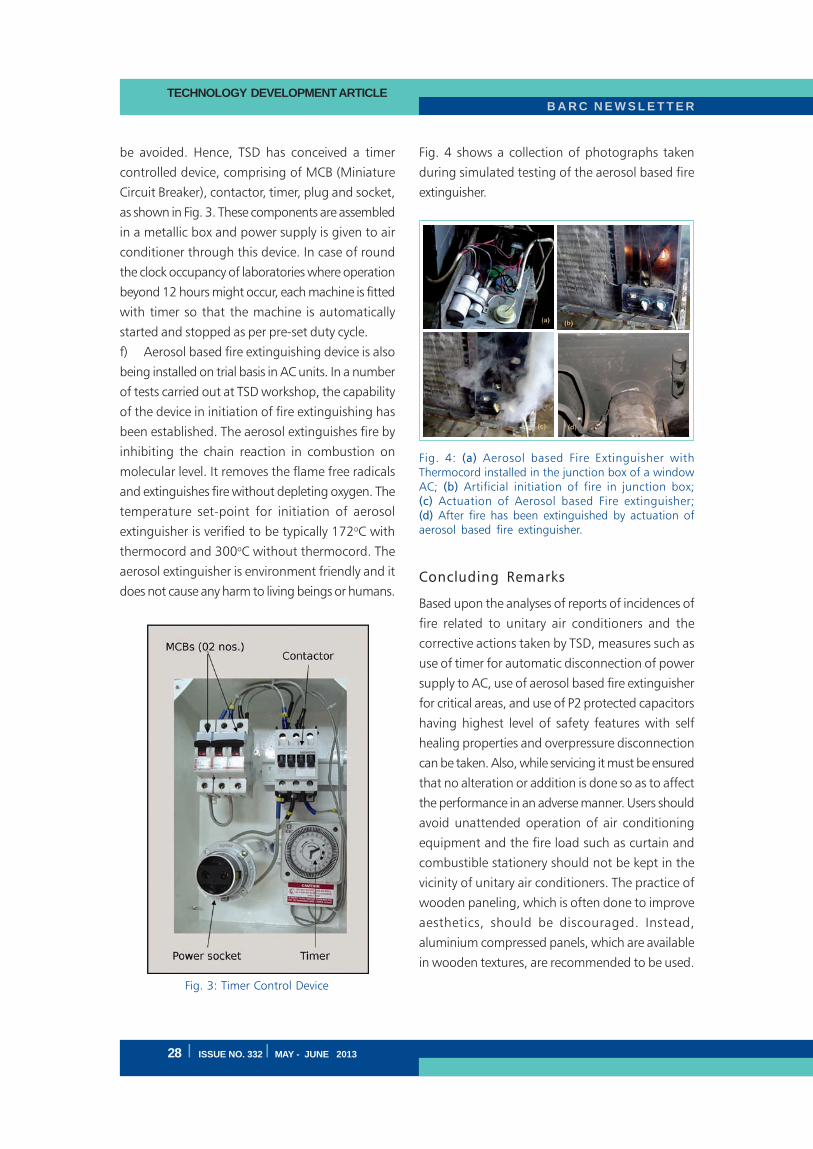
B A R C N E W S L E T T E RTECHNOLOGY DEVELOPMENT ARTICLE
28 I ISSUE NO. 332 I MAY - JUNE 2013
be avoided. Hence, TSD has conceived a timer
controlled device, comprising of MCB (Miniature
Circuit Breaker), contactor, timer, plug and socket,
as shown in Fig. 3. These components are assembled
in a metallic box and power supply is given to air
conditioner through this device. In case of round
the clock occupancy of laboratories where operation
beyond 12 hours might occur, each machine is fitted
with timer so that the machine is automatically
started and stopped as per pre-set duty cycle.
f) Aerosol based fire extinguishing device is also
being installed on trial basis in AC units. In a number
of tests carried out at TSD workshop, the capability
of the device in initiation of fire extinguishing has
been established. The aerosol extinguishes fire by
inhibiting the chain reaction in combustion on
molecular level. It removes the flame free radicals
and extinguishes fire without depleting oxygen. The
temperature set-point for initiation of aerosol
extinguisher is verified to be typically 172oC with
thermocord and 300oC without thermocord. The
aerosol extinguisher is environment friendly and it
does not cause any harm to living beings or humans.
Fig. 4 shows a collection of photographs taken
during simulated testing of the aerosol based fire
extinguisher.
Concluding Remarks
Based upon the analyses of reports of incidences of
fire related to unitary air conditioners and the
corrective actions taken by TSD, measures such as
use of timer for automatic disconnection of power
supply to AC, use of aerosol based fire extinguisher
for critical areas, and use of P2 protected capacitors
having highest level of safety features with self
healing properties and overpressure disconnection
can be taken. Also, while servicing it must be ensured
that no alteration or addition is done so as to affect
the performance in an adverse manner. Users should
avoid unattended operation of air conditioning
equipment and the fire load such as curtain and
combustible stationery should not be kept in the
vicinity of unitary air conditioners. The practice of
wooden paneling, which is often done to improve
aesthetics, should be discouraged. Instead,
aluminium compressed panels, which are available
in wooden textures, are recommended to be used.
Fig. 4: (a) Aerosol based Fire Extinguisher withThermocord installed in the junction box of a windowAC; (b) Artificial initiation of fire in junction box;(c) Actuation of Aerosol based Fire extinguisher;(d) After fire has been extinguished by actuation ofaerosol based fire extinguisher.
Fig. 3: Timer Control Device
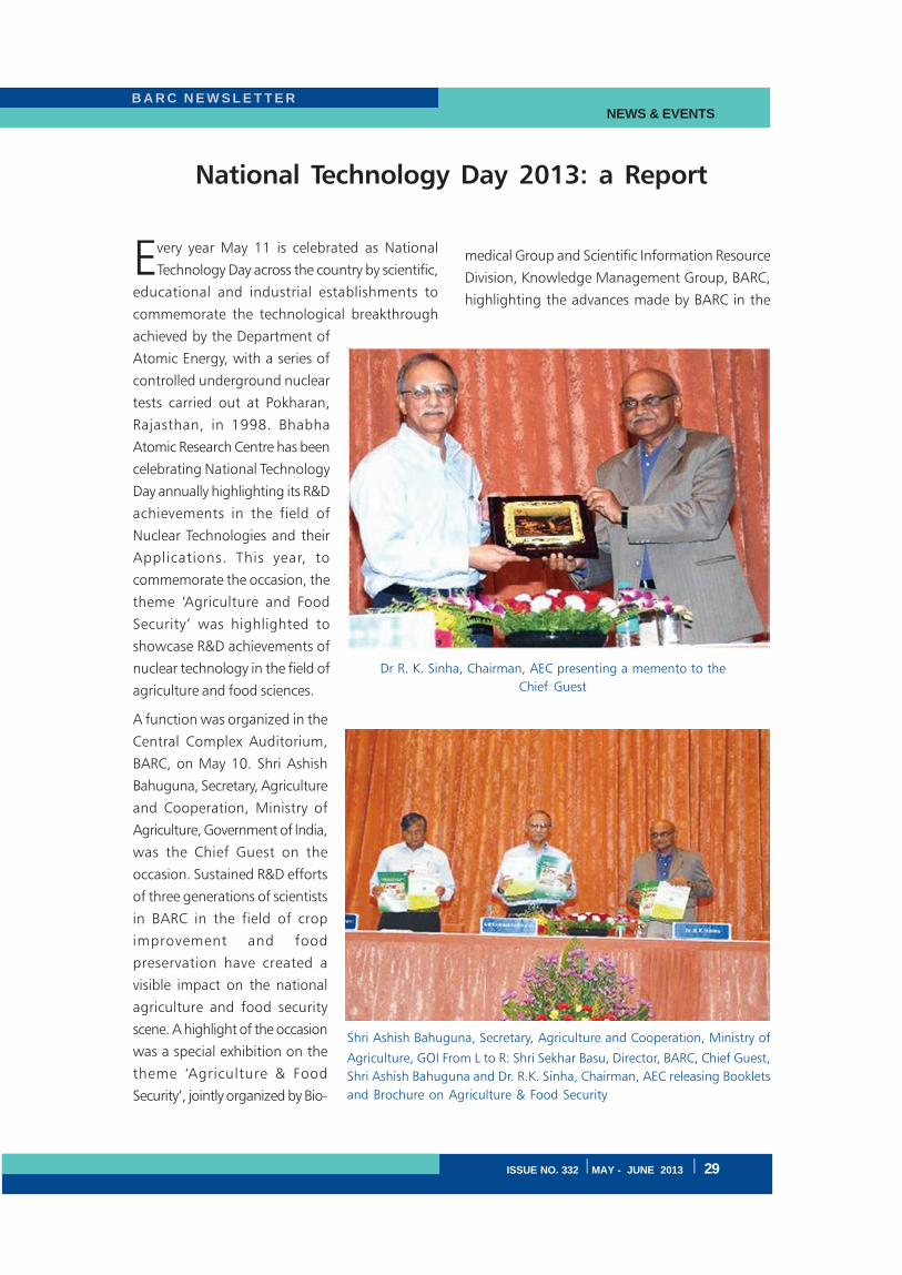
ISSUE NO. 332 I MAY - JUNE 2013 I 29
B A R C N E W S L E T T E R NEWS & EVENTS
National Technology Day 2013: a Report
Every year May 11 is celebrated as National
Technology Day across the country by scientific,
educational and industrial establishments to
commemorate the technological breakthrough
achieved by the Department of
Atomic Energy, with a series of
controlled underground nuclear
tests carried out at Pokharan,
Rajasthan, in 1998. Bhabha
Atomic Research Centre has been
celebrating National Technology
Day annually highlighting its R&D
achievements in the field of
Nuclear Technologies and their
Applications. This year, to
commemorate the occasion, the
theme ‘Agriculture and Food
Security’ was highlighted to
showcase R&D achievements of
nuclear technology in the field of
agriculture and food sciences.
A function was organized in the
Central Complex Auditorium,
BARC, on May 10. Shri Ashish
Bahuguna, Secretary, Agriculture
and Cooperation, Ministry of
Agriculture, Government of India,
was the Chief Guest on the
occasion. Sustained R&D efforts
of three generations of scientists
in BARC in the field of crop
improvement and food
preservation have created a
visible impact on the national
agriculture and food security
scene. A highlight of the occasion
was a special exhibition on the
theme ‘Agriculture & Food
Security’, jointly organized by Bio-
medical Group and Scientific Information Resource
Division, Knowledge Management Group, BARC,
highlighting the advances made by BARC in the
Dr R. K. Sinha, Chairman, AEC presenting a memento to the
Chief Guest
Shri Ashish Bahuguna, Secretary, Agriculture and Cooperation, Ministry of
Agriculture, GOI From L to R: Shri Sekhar Basu, Director, BARC, Chief Guest,
Shri Ashish Bahuguna and Dr. R.K. Sinha, Chairman, AEC releasing Booklets
and Brochure on Agriculture & Food Security
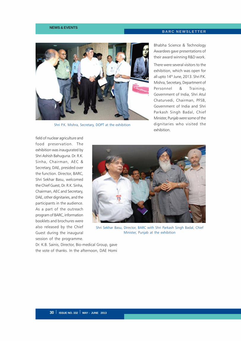
B A R C N E W S L E T T E RNEWS & EVENTS
30 I ISSUE NO. 332 I MAY - JUNE 2013
field of nuclear agriculture and
food preservation. The
exhibition was inaugurated by
Shri Ashish Bahuguna. Dr. R.K.
Sinha, Chairman, AEC &
Secretary, DAE, presided over
the function. Director, BARC,
Shri Sekhar Basu, welcomed
the Chief Guest, Dr. R.K. Sinha,
Chairman, AEC and Secretary,
DAE, other dignitaries, and the
participants in the audience.
As a part of the outreach
program of BARC, information
booklets and brochures were
also released by the Chief
Guest during the inaugural
session of the programme.
Dr. K.B. Sainis, Director, Bio-medical Group, gave
the vote of thanks. In the afternoon, DAE Homi
Shri P.K. Mishra, Secretary, DOPT at the exhibition
Shri Sekhar Basu, Director, BARC with Shri Parkash Singh Badal, Chief
Minister, Punjab at the exhibition
Bhabha Science & Technology
Awardees gave presentations of
their award winning R&D work.
There were several visitors to the
exhibition, which was open for
all upto 14th June, 2013. Shri P.K.
Mishra, Secretary, Department of
Personnel & Training,
Government of India, Shri Atul
Chaturvedi, Chairman, PFSB,
Government of India and Shri
Parkash Singh Badal, Chief
Minister, Punjab were some of the
dignitaries who visited the
exhibition.
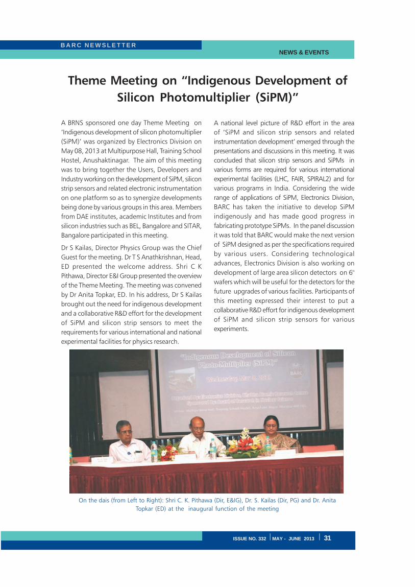
ISSUE NO. 332 I MAY - JUNE 2013 I 31
B A R C N E W S L E T T E R NEWS & EVENTS
Theme Meeting on “Indigenous Development of
Silicon Photomultiplier (SiPM)”
A BRNS sponsored one day Theme Meeting on
‘Indigenous development of silicon photomultiplier
(SiPM)’ was organized by Electronics Division on
May 08, 2013 at Multipurpose Hall, Training School
Hostel, Anushaktinagar. The aim of this meeting
was to bring together the Users, Developers and
Industry working on the development of SiPM, silicon
strip sensors and related electronic instrumentation
on one platform so as to synergize developments
being done by various groups in this area. Members
from DAE institutes, academic Institutes and from
silicon industries such as BEL, Bangalore and SITAR,
Bangalore participated in this meeting.
Dr S Kailas, Director Physics Group was the Chief
Guest for the meeting. Dr T S Anathkrishnan, Head,
ED presented the welcome address. Shri C K
Pithawa, Director E&I Group presented the overview
of the Theme Meeting. The meeting was convened
by Dr Anita Topkar, ED. In his address, Dr S Kailas
brought out the need for indigenous development
and a collaborative R&D effort for the development
of SiPM and silicon strip sensors to meet the
requirements for various international and national
experimental facilities for physics research.
A national level picture of R&D effort in the area
of ‘SiPM and silicon strip sensors and related
instrumentation development’ emerged through the
presentations and discussions in this meeting. It was
concluded that silicon strip sensors and SiPMs in
various forms are required for various international
experimental facilities (LHC, FAIR, SPIRAL2) and for
various programs in India. Considering the wide
range of applications of SiPM, Electronics Division,
BARC has taken the initiative to develop SiPM
indigenously and has made good progress in
fabricating prototype SiPMs. In the panel discussion
it was told that BARC would make the next version
of SiPM designed as per the specifications required
by various users. Considering technological
advances, Electronics Division is also working on
development of large area silicon detectors on 6"
wafers which will be useful for the detectors for the
future upgrades of various facilities. Participants of
this meeting expressed their interest to put a
collaborative R&D effort for indigenous development
of SiPM and silicon strip sensors for various
experiments.
On the dais (from Left to Right): Shri C. K. Pithawa (Dir, E&IG), Dr. S. Kailas (Dir, PG) and Dr. Anita
Topkar (ED) at the inaugural function of the meeting
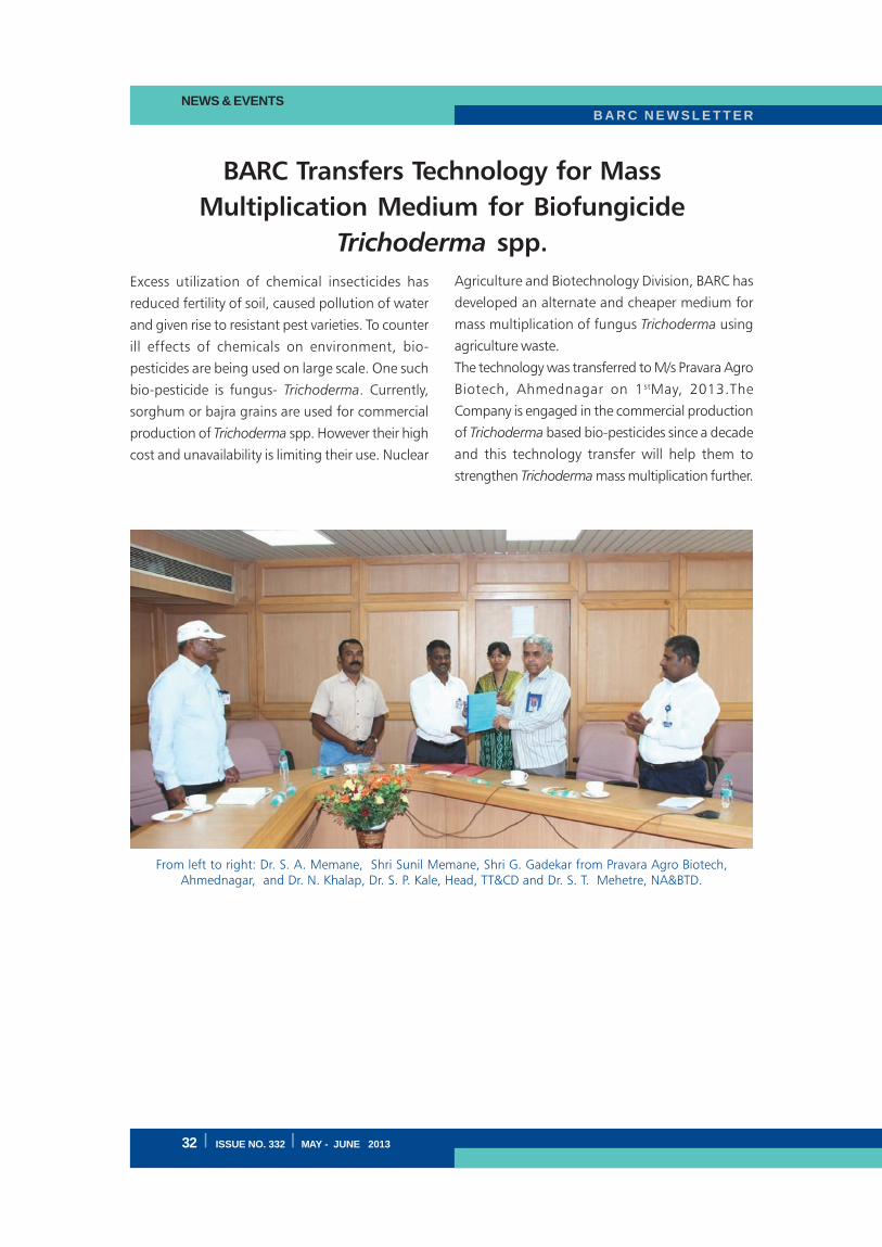
B A R C N E W S L E T T E RNEWS & EVENTS
32 I ISSUE NO. 332 I MAY - JUNE 2013
BARC Transfers Technology for Mass
Multiplication Medium for Biofungicide
Trichoderma spp.
Excess utilization of chemical insecticides has
reduced fertility of soil, caused pollution of water
and given rise to resistant pest varieties. To counter
ill effects of chemicals on environment, bio-
pesticides are being used on large scale. One such
bio-pesticide is fungus- Trichoderma. Currently,
sorghum or bajra grains are used for commercial
production of Trichoderma spp. However their high
cost and unavailability is limiting their use. Nuclear
From left to right: Dr. S. A. Memane, Shri Sunil Memane, Shri G. Gadekar from Pravara Agro Biotech,Ahmednagar, and Dr. N. Khalap, Dr. S. P. Kale, Head, TT&CD and Dr. S. T. Mehetre, NA&BTD.
Agriculture and Biotechnology Division, BARC has
developed an alternate and cheaper medium for
mass multiplication of fungus Trichoderma using
agriculture waste.
The technology was transferred to M/s Pravara Agro
Biotech, Ahmednagar on 1stMay, 2013.The
Company is engaged in the commercial production
of Trichoderma based bio-pesticides since a decade
and this technology transfer will help them to
strengthen Trichoderma mass multiplication further.

ISSUE NO. 332 I MAY - JUNE 2013 I
B A R C N E W S L E T T E R
B A R C N E W S L E T T E R
I ISSUE NO. 332 I MAY - JUNE 2013
Published by:
Scientific Information Resource Division,
Bhabha Atomic Research Centre, Trombay, Mumbai 400 085, India
BARC Newsletter is also available at URL:http:www.barc.gov.in
The pond at BARC