isolation improvement in a dual-band dual- element mimo antenna system … · progress in...
TRANSCRIPT

Progress In Electromagnetics Research, Vol. 134, 247–266, 2013
ISOLATION IMPROVEMENT IN A DUAL-BAND DUAL-ELEMENT MIMO ANTENNA SYSTEM USING CAPACI-TIVELY LOADED LOOPS
Mohammad S. Sharawi1, *, Ahmed B. Numan1, andDaniel N. Aloi2
1Electrical Engineering Department, King Fahd University forPetroleum and Minerals (KFUPM), Dhahran 31261, Saudi Arabia2Electrical and Computer Engineering Department, Oakland Univer-sity, Rochester, Michigan 48309, USA
Abstract—A dual-band dual-element multiple-input-multiple-output(MIMO) antenna system with enhanced isolation is proposed. TheMIMO antenna system is based on printed 4-shaped antenna elements.Dual band isolation is achieved by using an array of printed capacitivelyloaded loops (CLLs) on the top side of the board for high band isolationimprovement and a complementary CLL structure on the GND planeof the antenna for lower band isolation improvement. The lower bandof operation covers 827–853 MHz and the higher band covers 2.3–2.98GHz. Two prototypes were investigated to access the effect ofthe isolation mechanism. Measured isolation improvement of 10 dBwas observed in the lower operating band while the improvement inthe higher band was approximately 2.5 dB. The isolation improvementwas at the expense of 5% reduction in efficiency. The measured gainpatterns as well MIMO figures of merits such as the correlation factor,TARC and MEG were investigated as well.
1. INTRODUCTION
Fourth generation wireless systems (also called Long Term Evolution— LTE) rely on the use of multiple-input-multiple-output (MIMO)antenna systems integrated within the user terminals in order toachieve higher data rates and multimedia capabilities. This poses achallenge in terms of the antenna size and the achievable isolation
Received 6 September 2012, Accepted 6 November 2012, Scheduled 24 November 2012* Corresponding author: Mohammad S. Sharawi ([email protected]).

248 Sharawi, Numan, and Aloi
between adjacent radiating elements that affects the overall diversityperformance of the system [1–3].
Improving the isolation between adjacent MIMO antennas isa challenging task especially for technologies that operate at lowfrequency bands (Low frequency LTE bands). There are a numberof techniques that are used to enhance the isolation between theantennas. Reported techniques in literature include the introduction ofthe decoupling structures [4], modifications in the ground plane [5–7],lumped component filters [8], neutralization strips [9–11], introductionof resonating structures near the antennas [12], antenna orientation [13]and the use of metamaterials [14–16].
Metamaterials are artificially engineered materials that possessproperties not found in nature (i.e., negative permittivity orpermeability). These materials are usually realized by periodicallyrepeating a basic unit element (UE) structure. Metamaterials canexhibit stop band filter properties [17]. This property is used to isolateclosely packed antennas. Thus, the metamaterial should be designedproperly to have a stop band at the desired frequency.
Capacitively loaded loops (CLLs) were introduced in [18–20].They were modeled in [21] using method of moment (MoM) and aninterpolation scheme. The resonance frequency is determined by theconfiguration and physical dimensions of the loop. A metamaterial canbe realized by periodically placing copies of the UE (i.e., the CLL). Thedimensions of CLL determine the band in which the material will havemetamaterial properties.
In [14], a MIMO antenna system consisting of two monopoleantennas separated by 0.18 wavelengths operating at 2.6 GHz forWiMAX applications was proposed. The metamaterial betweenthe antennas is formed using two different configurations of CLLs.6 dB isolation improvement was obtained. In [15], non-planar splitring resonators (SRRs) were used to enhance the isolation betweentwo radiating elements (monopoles) operating in the 3.38–3.7 GHzfrequency band. The maximum isolation within the desired bandwas improved by about 3 dB. In [16], a metamaterial based channelisolator was introduced to enhance the isolation between two printedspiral MIMO antennas operating in the commercial ISM band around2.5GHz. This isolation method realizes an artificial magnetic wall thatdecouples the radiating elements from coupling through the magneticfield. The magnetic wall improved the isolation by 24 dB. This methodis only applicable for spiral antenna types.
Almost all the work that appeared in literature to enhance theisolation between adjacent MIMO antennas focused on high frequencybands (above 1 GHz) as size of UE increases as the frequency of

Progress In Electromagnetics Research, Vol. 134, 2013 249
operation decreases. Large size UE violate the strict constraints onthe area of a printed MIMO antenna system especially for handhelddevices. This work focuses on improving the isolation between adjacentMIMO antenna elements operating in the sub-GHz frequencies usingspiral-like CLLs. The CLL selected has the tendency of having highervalues of capacitance and inductance in a limited area by varying theparameters of the spirals associated with the UE and hence the stopband can be achieved at low frequencies. In addition to the lowerfrequency metamaterial design, this work proposes a metamaterialconfiguration that covers the higher band of operation as well, thusthe complete structure is suitable for enhancing the isolation of dual-band MIMO antenna systems.
The 4-shaped MIMO antenna system with its novel antennaelement geometry first appeared in [22] and [23]. This antenna isa dual band one and its measured isolation in the low band wasvery poor. The proposed isolation mechanism for dual band isolationenhancement using spiral like CLL arrays is applied to the dual band4-shaped MIMO antenna system. The simulated and measured MIMOantenna performance metrics such as the s-parameters, gain patterns,total active reflection coefficient (TARC) as well as the mean effectivegain (MEG) are presented and discussed. An isolation improvement of10 dB in the low band and 2.5 dB in the high band are observed withthis new isolation mechanism. This of course came as a trade off withlowering the efficiency of the MIMO antenna system by approximately5%.
The rest of the paper is organized as follows: Section 2 describesthe modeling of the dual band 2× 1 MIMO antenna system with theproposed CLL isolation arrays. Section 3 presents and compares thesimulation and measurement results and Section 4 concludes the paper.
2. THE 2 × 1 MIMO ANTENNA DESIGN WITH CLLs
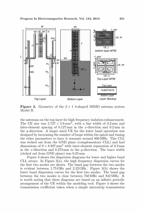
The original 2×1 MIMO antenna system of 4-shaped elements is shownin Figure 1. Please note that the top layer has the antennas while thebottom layer has the ground plane. This model is called Model A fromnow on. The basic antenna element has the shape of the number 4, andhence it is called the 4-shaped antenna. The modified MIMO antennasystem with the added capacitively loaded loops (CLLs) on the topside and etched out from the GND plane at the bottom side is shownin Figure 2. This antenna model is called Model B from now on. Theantennas were designed and optimized using the field solver HFSSTM .
The dimensions of the 2 × 1 dual band MIMO antenna Model Awere (in mm): W = 50, L = 100, Wt = 2.2, H = 2.5493, L1 = 40.75,

250 Sharawi, Numan, and Aloi
Wt
L1
L2
YsYf
Wf
Xf
Xs
Lf
Xa2
H
W
L
W1
Y
W2
TOP LAYER
SUBSTRATE
BOTTOM LAYER
Top Layer Bottom Layer
Layer Stackup
Y
XZ
Ws
Figure 1. Geometry of the 2 × 1 4-shaped MIMO antenna systemModel A.
L2 = 27, Ys = 5.5, Xa2 = 1.6716, Lf = 15.8, Xs = 0.6716,Xf = 2.6716, Wf = 2.5, Ws = 1, Yf = 15.5, W1 = 10, Y = 46 andW2 = 17. The antenna was printed on an FR-4 substrate of thickness1.56mm, 1 oz. copper plating and a dielectric constant of 4.4. Theoverall size of the two-element dual band MIMO antenna system was50× 100× 1.56mm3.
The top side CLLs were designed to operate at 2.75GHz, becauseit is the the resonance frequency of the 4-shaped antenna at thehigh band before applying the CLLs. The resonance frequency ofthe metamaterial unit element (UE) (or unit cell) depends on theinductance and capacitance of the structure. The gap between thespiral traces need to be increased in order to lower these values.Similarly the number of edges of the spirals associated with UEs shouldalso be reduced along with the reduction of the size of unit cell. Thisreduces the length of coupled edges which results in a reduction of thecapacitance and inductance associated with the UE structure. Thus,a small UE with a higher gap and small number of the spiral edgesresonates at higher frequencies. An array of UE was deployed between
Progress In Electromagnetics Research, Vol. 134, 2013 251
W
L
W1
Y
Y1
W2
UE_L
UE_W
Gap
X_dis
t
UE_L
UE_W
Y_dist
Wtrace
Gap
UE_L1
UE_W1
Y_dist1
Wtrace1
Wtrace1
Gap1
X_dis
t1
Top Layer
SUBSTRATE
Bottom Layer
Top Layer Bottom Layer Layer Stackup
bottom layer MTM
Top Layer MTM
L2
L1L3
UE_W1
UE
_L
1
H
Xa2
Lf
Xs
XfYf
Yf2
Yf
Wf
Wtr
W50
Ys
Wt
Y
XZ
Ws1
3
Figure 2. Geometry of the 2 × 1 4-shaped MIMO antenna systemModel B.
the antennas on the top layer for high frequency isolation enhancement.The UE size was 5.727 × 5.8mm2, with a line width of 0.2 mm andinter-element spacing of 0.127 mm in the x-direction and 0.2 mm inthe y-direction. A larger sized UE for the lower band operation wasdesigned by increasing the number of loops within the spiral and tuningthe other parameters to have it resonate around 800MHz. This CLLwas etched out from the GND plane (complementary CLL) and haddimensions of 9 × 8.927mm2 with inter-element separation of 0.2 mmin the x-direction and 0.273 mm in the y-direction. The trace width(etched out from GND plane) was 0.25 mm.
Figure 3 shows the dispersion diagrams for lower and higher bandCLL arrays. In Figure 3(a), the high frequency dispersion curves forthe first two modes are shown. The band gap between the two modesis evident between 1.75GHz and 2.22 GHz. Figure 3(b) shows thelower band dispersion curves for the first two modes. The band gapbetween the two modes is clear between 750MHz and 842 MHz. Itis worth noting that these diagrams are based on an infinite periodicarrangement of the UE within the modeling tool. Figure 4 shows thetransmission coefficient taken when a simple microstrip transmission

252 Sharawi, Numan, and Aloi
0 20 40 60 80 100 120 140 160 1801
1.5
2
2.5
Bl
Fre
qu
en
cy (
GH
z) Mode1
Mode2
0 20 40 60 80 100 120 140 160 180500
600
700
800
900
1000
1100
Fre
qu
en
cy (
MH
z)
(a)
(b)Bl
Figure 3. Dispersion curves for the (a) high and (b) low band CLLarrays.
0.5 1 1.5 2 2.5 3-18
-16
-14
-12
-10
-8
-6
-4
-2
0
Frequency (GHz)
Tra
nsm
issio
n C
oe
ffic
ien
t (d
B)
Figure 4. Transmission coefficient of the proposed printed CLLarrays.
line is passed over the top and bottom CLL arrays. An extra layerof 0.07mm thickness was added for the microstrip line to test thetransmission coefficient. The isolation in the lower band centered at

Progress In Electromagnetics Research, Vol. 134, 2013 253
940MHz and higher bands at 2 GHz and 2.5GHz are clear. Thesevalues were tuned to operate within the bands of interest when theCLL arrays were applied between the antennas.
The dimensions of Model B were (in mm): W = 50, L = 100,Wt = 2.2, H = 6.9635, L1 = 35.3, L2 = 26, Ys = 5.5, Xa2 = 4.0716,Lf = 14.7, Xs = 0.3716, Xf = 1.5716, Wf = 2.5, Ws = 1, Wtr = 1.4,W50 = 3, Yf1 = 13.35, Yf2 = 13.5, Yf3 = 28.65, UE W1 = 5.727,UE L1 = 5.8, L3 = 35.8, W1 = 12.2, UE W = 9, UE L = 8.927,Y1 = 64.127, Y = 44, W2 = 15.9, Y dist = 0.273, Gap = 0.127,X dist = 0.2, Wtrace=0.25, Y dist1 = 0.2, X dist1 = 0.127, GAP1 =0.36, Wtrace1 = 0.2.
3. RESULTS AND DISCUSSION
Figure 5 shows the fabricated antenna structure of Model A (Top andBottom views) while Figure 6 shows the fabricated MIMO antennaModel B. The S-parameter measurements for these 2 × 1 4-shapedMIMO antenna system are shown in Figure 7 for the low and highbands of operation for Model A, and in Figure 8 for the low and highbands of operation of Model B. A 50 Ω termination was used on theother port during the Sii measurement, where i ∈ [1, 2]. Figure 7(a)shows the measured and simulated S-parameter curves for the lowerband for antenna elements 1 and 2 covering the 762–790 MHz. A
(a) (b)
Figure 5. Fabricated dual-band 4-shaped MIMO antennasystem Model A. (a) Top side.(b) Bottom side.
(a) (b)
Figure 6. Fabricated dual-band 4-shaped MIMO antennasystem Model B. (a) Top side.(b) Bottom side.

254 Sharawi, Numan, and Aloi
700 720 740 760 780 800 820 840 860 880 900-35
-30
-25
-20
-15
-10
-5
0
Frequency (MHz)
S-p
ara
mete
rs (
dB
)
sim S11sim S12sim S22exp S11exp S12exp S22
(a)
2.3 2.4 2.5 2.6 2.7 2.8 2.9 3-35
-30
-25
-20
-15
-10
-5
0
Frequency (GHz)
S-p
ara
mete
rs (
dB
)
sim S11sim S12sim S22exp S11exp S12exp S22
(b)
Figure 7. S-parameter measurements of the fabricated 2×1 4-shapedMIMO antenna Model A. (a) Lower band. (b) Upper band.
−6 dB bandwidth (BW) of 28 MHz was obtained†. Figure 7(b) showsthe measured and simulated S-parameter curves for the upper bandfor elements 1 and 2 covering 2.45–2.625 GHz and 2.485–2.61GHz,respectively. A −6 dB BW of more than 125 MHz was obtained.The discrepancies between the measured and simulated curves aredue the fabrication process. The minimum measured isolation in thelower band was approximately 9.5 dB while in the upper band it wasapproximately 7.1 dB.
The results for Model B are shown in Figure 8. Figure 8(a) showsthe lower band S-parameter measurements, while Figure 8(b) showsthe higher band ones. The lower band covered the frequency ranges† The −6 dB BW is widely accepted for evaluating closely packed MIMO antenna systemssuch as in [24–27].

Progress In Electromagnetics Research, Vol. 134, 2013 255
700 720 740 760 780 800 820 840 860 880 900 -35
-30
-25
-20
-15
-10
-5
0
Frequency(MHz)
S-p
ara
me
ters
(dB
)exp S11exp S12exp S22
(a)
2.3 2.4 2.5 2.6 2.7 2.8 2.9 3 -35
-30
-25
-20
-15
-10
-5
0
Frequency(GHz)
S-p
ara
me
ters
(d
B)
exp S11
exp S12
exp S22
(b)
Figure 8. S-parameter measurements of the fabricated 2×1 4-shapedMIMO antenna Model B. (a) Lower band, (b) Upper band.
from 827–853 MHz and 831–856MHz for elements 1 and 2, respectively.A minimum −6 dB BW of 26 MHz was measured. The higher bandcovered from 2.3–2.98 GHz for both elements 1 and 2. The measured−6 dB BW was 640 MHz. The minimum measured isolation in thelower band was improved by about 10 dB to reach 18.9 dB after theintroduction of CLLs in the top and bottom layers. The minimummeasured isolation in higher band of operation was improved byapproximately 2.5 dB to reach 9.8 dB. Note that the spatial separationat the lower band (800MHz) is less than λ0/15, which justifies theuse of CLLs to improved the isolation. Although the addition of CLLarrays improved the isolation in both bands, it shifted the resonancefrequency of the lower band upwards by approximately 65 MHz. It alsowidened the upper band BW.

256 Sharawi, Numan, and Aloi
The original impedance of Model B was not 50 Ω. This means thatthe antenna response varies as we change the length of the feed line. Animpedance transformer is introduced to match the antenna impedance.The impedance transformer should be capable of providing acceptablematch at both bands. The low band impedance is matched viatuning the antenna structure and we used a λ/4 microstrip impedancetransformer for the high band matching. After tuning the antennawithout the introduction of the impedance transformer, the inputimpedance becomes (48.32 + j2.6)Ω at 840MHz and (117.3 + j0.61)Ωat 2.75 GHz. After placing and tuning the microstrip impedancetransformer (length = 13.5mm, width = 1.4mm), we obtain (42.4 −j0.36)Ω at 840 MHz and (57.7 − j6.03)Ω at 2.85 GHz. So theimpedance is almost matched to 50 Ω. The impedance at the low bandis not much affected by the microstrip impedance transformer. Thefeeding positions of Models A and B were located at the points of 50 Ωmatching. The impedance transformer was optimized to give goodinput matching while maintaining the maximum isolation levels.
The effect of the CLL arrays on the current distribution on theantenna elements and the GND plane are shown for the two bands andtwo antenna models in Figure 9. Figures 9(a) and (b) compare side byside the current distributions of Models A and B in the lower band ofoperation, while Figures 9(c) and (d) compare side by side the currentdistributions of Models A and B in the higher band of operation. It isclear that the introduction of the CLLs on the top and bottom layers ofthe antenna had a major influence on the current distribution that ineffect enhanced the coupling between the two closely packed antennaelements in both the lower and higher bands of operation.
The measured gain patterns of the proposed MIMO antennasystem were obtained using an outdoor antenna range facility atOakland University, Michigan, USA. Figure 10 shows the measurednormalized radiation gain patterns of the MIMO antenna systemproposed at 775 MHz and 2550 MHz bands for Model A. The 775 MHzx-z plane (elevation plane with φ = 0) is shown in Figure 10(a) whilethe y-z (elevation plane with φ = 90) plane is shown in Figure 10(b).In both figures, the co-pol and cross-pol patterns for antenna elements1 and 2 are shown. The maximum measured gain at 775 MHz was−4 dBi. Similarly, the x-z and y-z plane cut gain patterns for antennaelements 1 and 2 at 2550MHz are shown in Figures 10(c) and (d),respectively. The maximum measured gain at the high band was2.5 dBi. The low band efficiency was ηlow = 40% while the high bandone was ηhigh = 75%.
The measured normalized gain patterns of Model B are shown inFigure 11 for the low and high bands of operation. The 840 MHz x-z

Progress In Electromagnetics Research, Vol. 134, 2013 257
(a) (b)
(c) (d)
Figure 9. Current distribution plots. (a) Model A at 755 MHz.(b) Model B at 840 MHz. (c) Model A at 2550 MHz. (d) Model Bat 2850 MHz.
plane (elevation plane with φ = 0) is shown in Figure 11(a) while they-z (elevation plane with φ = 90) plane is shown in Figure 11(b). Inboth figures, the co-pol and cross-pol patterns for antenna elements1 and 2 are shown. The maximum measured gain at 840 MHz was−2.8 dBi. Similarly, the x-z and y-z plane cut gain patterns forantenna elements 1 and 2 at 2850 MHz are shown in Figures 11(c)and (d), respectively. The maximum measured gain at the high bandwas 5.5 dBi. The low band efficiency was ηlow = 35% while the highband one was ηhigh = 67%. The introduction of the MTM lowered theefficiency of the antenna at both bands, introduced several dips in thegain pattern and increased its directivity. The discrepancies between

258 Sharawi, Numan, and Aloi
-30-25-20-15-10-5 0
60
300
330
300
270
120
150180
210
240
90
(a)
-30 -25 -20-15-10 -5 0
60
300
330
300
270
120
150180
210
240
90
(b)
-30 -25 -20-15-10-5 0
60
300
330
300
270
120
150180
210
240
90
(c)
-30 -25 -20 -15 -10-5 0
60
300
330
300
270
120
150180
210
240
90
(d)
Figure 10. Measured gain patterns for the proposed MIMO antennaModel A. (a) x-z plane at 755MHz. (b) y-z plane at 755 MHz. (c) x-z plane at 2550 MHz. (d) y-z plane at 2550 MHz. Dots is co-polelement 1, Circles is co-pol element 2, solid is cross-pol element 1,dashes is cross-pol element 2.
some of the patterns of elements 1 and 2 are believed to be due to themeasurement setup and antenna mounting on the plastic stand. Thepattern dip occurring might be due to placing it close to the standedge or because of placing some tape on top of it. The relatively lowefficiency at the lower band of operation is attributed to the fact thatthe basic antenna element (4-shaped antenna) is an electrically smallone. And thus, adding the CLLs as isolation enhancement elementsonly degraded the efficiency by 5%. This is a tradeoff that the designershould be aware of when using ESA as well as MTM based structuresas was also indicated in [28, 29].
The MIMO antenna system correlation factor will be significantlydegraded with higher coupling levels. It can be calculated from

Progress In Electromagnetics Research, Vol. 134, 2013 259
-30 -25 -20 -15 -10 -5 0
60
300
330
300
270
120
150180
210
240
90
(a)
-30 -25 -20 -15 -10 -5 0
60
300
330
300
270
120
150180
210
240
90
(b)
-30 -25 -20 -15
-10 -5 0
60
300
330
300
270
120
150180
210
240
90
(c)
-30 -25 -20 -15
-10 -5 0
60
300
330
300
270
120
150180
210
240
90
(d)
Figure 11. Measured Gain patterns for the proposed MIMO antennaModel B. (a) x-z plane at 840 MHz. (b) y-z plane at 840MHz. (c) x-z plane at 2850 MHz. (d) y-z plane at 2850 MHz. Dots is co-polelement 1, Circles is co-pol element 2, solid is cross-pol element 1,dashes is cross-pol element 2.
the measured s-parameters in isotropic/uniform signal propagationenvironments [30]. The correlation factor (ρ) is important to achievethe required diversity gain of the MIMO antenna system. The lowerthe ρ value, the higher the diversity gain. The antenna efficiency isalso another factor needed for determining the correlation factor. Thevalue of ρ can be calculated using:
|ρij | =|S∗iiSij + S∗ijSjj |√
|(1− |S2ii| − |S2
ji|)(1− |S2jj | − |S2
ij |)ηiηj |(1)
Even with the presence of the relatively low isolation valuesspecially in the higher band (approximately 10 dB), the calculated

260 Sharawi, Numan, and Aloi
values of the correlation factor for Model B at the the lower and higherbands of operation were less than 0.11 and 0.18, respectively. Figure 12shows the lower band and higher band correlation factor curves forModel B. It is evident that this MIMO antenna system with enhancedisolation will satisfy the LTE requirements for spatial diversity sincethe values of |ρ| ≤ 0.3 for the bands of interest [2].
The total active reflection coefficient (TARC) is considered theMIMO array radiation efficiency for multi-ports antennas [31]. It iscalculated by finding the ratio between the square root of the totalreflected power divided by the square root of the total incident power,
700 720 740 760 780 800 820 840 860 880 9000
0.05
0.1
0.15
0.2
0.25
0.3
0.35
0.4
0.45
0.5
Frequency (MHz)
Co
rre
latio
n c
oe
ffic
ien
t
(a)
2.3 2.4 2.5 2.6 2.7 2.8 2.9 30
0.05
0.1
0.15
0.2
0.25
0.3
0.35
0.4
0.45
0.5
Frequency (GHz)
Co
rre
latio
n c
oe
ffic
ien
t
(b)
Figure 12. Correlation factor |ρ12| curves for Model B. (a) Lowerband, (b) higher band of operation.

Progress In Electromagnetics Research, Vol. 134, 2013 261
it is found using:
Γ =
√|(S11 + S12ejθ)|2 + |(S21 + S22ejθ)|2√
2(2)
where θ is the phase angle between the two ports. Figure 13 showsthe TARC curves for the low band and high band of operation forModel B. The phase differences were swept between 0 and 180 degreesin 30 degree steps. It is evident that the TARC for the low band isalmost always less than −6 dB, while in the high band, it goes up to−4 dB. TARC values become worse when 180 phase difference betweenthe two port waves is considered (when out of phase incident signalson element 2 with respect to element 1). Such levels have also beenreported to give good diversity gain as indicated in [32].
700 720 740 760 780 800 820 840 860 880 900 -25
-20
-15
-10
-5
0
Frequency (MHz)
TA
RC
(d
B)
0degree30degree60degree90degree120degree150degree180degree
(a)
2.3 2.4 2.5 2.6 2.7 2.8 2.9 3-25
-20
-15
-10
-5
0
Frequency (GHz)
TA
RC
(d
B)
0degree30degree60degree90degree120degree150degree180degree
(b)
Figure 13. TARC curves for Model B. (a) Lower band, (b) higherband of operation.

262 Sharawi, Numan, and Aloi
In addition to ρ and TARC, the mean effective gain (MEG)is another parameter that directly affect the diversity gain andperformance of a MIMO antenna system. MEG can be calculatedby finding the ratio of the mean received power to the mean incidentpower of the antenna. This is found using [33]:
MEG =∮ [
XPD1 + XPD
pθ(Ω)Gθ(Ω) +1
1 + XPDpφ(Ω)Gφ(Ω)
]dΩ (3)
where XPD is the cross-polarization discrimination of the incident field(ratio between the vertical and horizontal power densities), pθ and pφ
are the θ and φ components of the probability distribution functionsof the incoming wave, respectively. Gθ and Gφ are the power gainpatterns of the antenna. Following the same mobile communicationschannel assumptions as in [34] MEG can be evaluated using,
MEG =12π
∫ 2π
0
[XPD
1+XPDGθ
(π
2, φ
)+
11+XPD
Gφ
(π
2, φ
)]dφ (4)
The calculated MEG values for the proposed antenna system forthe low bands and high bands with cross-polarization discrimination(XPD-Γ) of 0 dB and 6 dB are presented in Table 1 for both ModelsA and B. It is evident that the ratio of MEG1/MEG2 < 3 dB at bothbands of operation with both XPD values. This will provide acceptablediversity gain as indicated in [33]. In addition, Table 1 showsthe minimum isolation levels, minimum efficiencies and maximumcorrelation coefficient values in the band of operation of the modelsproposed.
Table 1.
Frequency
(MHz)
Min.
Isolation
(dB)
Min.
η
(%)
|ρ12|MEG1
(XPD
= 0 dB)
MEG2
(XPD
= 0 dB)
MEG1
(XPD
= 6dB)
MEG2
(XPD
= 6dB)
755
(Model-A)9.5 40 0.4 −10.0 −9.98 −13.83 −13.83
2550
(Model-A)7.1 75 0.15 −2.94 −2.97 −6.73 −6.75
840
(Model-B)18.9 35 0.11 −10.15 −10.16 −13.94 −13.94
2850
(Model-B)9.8 67 0.18 −3.2 −3.24 −7.13 −7.1

Progress In Electromagnetics Research, Vol. 134, 2013 263
4. CONCLUSIONS
The design and fabrication of two dual-element dual-band MIMOantenna systems based on 4-shaped printed antenna structures wasrepresented. An isolation enhancement method for the dual bands wasintroduced and investigated. The isolation method was based on usingarrays of CLLs on the top layer of the PCB while complementaryCLLs were used on the bottom layer of the board. The MIMOantenna system covers 827–853 MHz and 2.3–2.98GHz. The isolationimprovement was more than 10 dB in the lower band and 2.5 dB inthe higher band. Measured antenna gain patterns were presented. Amaximum gain of 5.5 dB was obtained in the higher band while−2.8 dBwas obtained in the lower band. The correlation factor, TARC andMEG values of this MIMO antenna system were also calculated andshown to provide good diversity performance.
ACKNOWLEDGMENT
This work was supported by project number RG1219 through theDeanship of Scientific Research at KFUPM, Dhahran, Saudi Arabia.
REFERENCES
1. Song, L. and J. Shen, Evolved Cellular Network Planning andOptimization for UMTS and LTE, CRC Press, 2011.
2. 3GPP TS 36.101, V8.3.0, “EUTRA User Equipment RadioTransmission and Reception,” September 2008.
3. Gesbert, D., S. Mansoor, S. Da-shan, P. J. Smith, and A. Naguib,“From theory to practice: An overview of MIMO space-time codedwireless systems,” IEEE J. Sel. Areas Commun., Vol. 21, No. 3,281–302, Apr. 2003.
4. Yoo, S. and S. Kahng, “A compact MIMO antenna usingZOR split ring resonator radiators with a decoupling structure,”Microwave Journal, Vol. 54, No. 11, S26–S31, November 2011.
5. Li, H., J. Xiong, Z. Ying, and S. He, “High isolation compactfour-port MIMO antenna systems with built-in filters as isolationstructure,” Proceedings of the Fourth European Conference onAntennas and Propagation (EuCAP), 1–4, 2010.
6. Chou, H. T., H. C. Cheng, H. T. Hsu, and L. R. Kuo,“Investigations of isolation improvement techniques for MultipleInput Multiple Output (MIMO) WLAN portable terminal

264 Sharawi, Numan, and Aloi
applications,” Progress In Electromagnetics Research, Vol. 85,349–366, 2008.
7. Zhu, F., J. Xu, and Q. Xu, “Reduction of mutual coupling betweenclosely-packed antenna elements using defected ground structure,”Electronics Letters, Vol. 45, No. 12, 601–602, 2009.
8. Han, M. and J. Choi, “Multiband MIMO antenna with a band stopfilter for high isolation characteristics,” Antennas and PropagationSociety International Symposium, 1–4, 2009.
9. Yeom, I., J. Kim, and C. Jung, “Compact dual-band MIMOantenna with high isolation performance,” Asia-Pacific MicrowaveConference Proceedings (APMC), 766–769, 2010.
10. Li, Z., M. Han, X. Zhao, and J. Choi, “MIMO antenna withisolation enhancement for wireless USB dongle application atWLAN band,” Antennas and Propagation Society InternationalSymposium, 758–761, 2010.
11. Lee, C., S. Chen, and P. Hsu, “Integrated dual planar inverted-Fantenna with enhanced isolation,” IEEE Antennas and WirelessPropagation Letters, Vol. 8, 963–965, 2009.
12. Min, K., D. Kim, and Y. Moon, “Improved MIMO antenna bymutual coupling suppression between elements,” The EuropeanConference on Wireless Technology, 125–128, 2005.
13. Karaboikis, M., C. Soras, G. Tsachtsiris, and V. Makios,“Compact dual-printed inverted-F antenna diversity systemsfor portable wireless devices,” IEEE Antennas and WirelessPropagation Letters, Vol. 3, No. 1, 9–14, 2004.
14. Hsu, C., K. Lin, H. Su, H. Lin, and C. Wu, “Design of MIMOantennas with strong isolation for portable applications,” IEEEAntennas and Propagation Society International Symposium, 1–4,2009.
15. Lee, Y., H. Chung, J. Ha, and L. Choi, “Design of aMIMO antenna with improved isolation using meta-material,”International Workshop on Antenna Technology (iWAT’11), 231–234, 2011.
16. Sarabandi, K. and Y. J. Song, “Subwavelength radio repeatersystem utilizing miniaturized antennas and metamaterial channelisolator,” IEEE Transactions on Antennas and Propagation,Vol. 59, No. 7, 2683–2690, 2011.
17. Marques, R., F. Martin, and M. Sorolla, Metamaterialswith Negative Parameters: Theory, Design and MicrowaveApplications, John Wiley and Sons, 2011.
18. Guo, Y. and R. Xu, “Planar metamaterials supporting multiple

Progress In Electromagnetics Research, Vol. 134, 2013 265
left-handed modes,” Progress In Electromagnetics Research,Vol. 66, 239–251, 2006.
19. Hrabar, S., Z. Eres, and J. Bartolic, “Capacitively loaded loopas basic element of negative permeability meta-material,” 32ndEuropean Microwave Conference, 1–4, 2002.
20. Goussetis, G., A. P. Feresidis, S. Wang, Y. Guo, and J. C. Vardax-oglou, “Uniplanar left-handed artificial metamaterials,” J. Opt. A:Pure Appl. Opt., Vol. 7, No. 2, S44, 2005.
21. Guo, Y., G. Goussetis, A. P. Feresidis, and J. C. Vardaxoglou,“Efficient modeling of novel uniplanar left-handed metamaterials,”IEEE Transactions on Microwave Theory and Techniques, Vol. 53,No. 4, 1462–1468, 2005.
22. Jan, M. A., D. N. Aloi, and M. S. Sharawi, “A 2×1 compact dualband MIMO antenna system for wireless handheld terminals,”IEEE Radio and Wireless Symposium (RWS 2012), Santa Clara,California, January 2012.
23. Sharawi, M. S., M. A. Jan, and D. N. Aloi, “A 4-shaped 2 × 2multi-standard compact MIMO antenna system for LTE mobilehandsets,” IET Microwaves, Ant. and Prop., Vol. 6, No. 6, 685–696, June 2012.
24. Sonkki, M., E. Antonino-Daviu, M. Cabedo-Fabres, M. Ferrando-Bataller, and E. T. Salonen, “Improved planar wideband antennaelement and its usage in a mobile MIMO system,” IEEE Antennasand Wireless Propagation Letters, 1, 2012.
25. Lee, C. J., W. Huang, A. Gummalla, and M. Achour, “ Smallantennas based on CRLH structures: Concept, design, andapplications,” IEEE Antennas and Propagation Magazine, Vol. 53,No. 2, 10–25, 2011.
26. Han, M.-S. and J. Choi, “MIMO antenna using a decouplingnetwork for next generation mobile application,” 9th InternationalSymposium on Communications and Information Technology(ISCIT’09), Icheon, South Korea, September 2009.
27. Lopez, N., C. Lee, A. Gummala, and M. Achour, “Compactmetamaterial antenna array for Long Term Evolution (LTE)handset application,” IEEE International Workshop on AntennaTechcnology (iWAT’09), Santa Monica, California, March 2009.
28. Lee, S. and J. Lee, “Electrically small MNG ZOR antennawith multilayered conductor,” IEEE Antennas and WirelessPropagation Letters, Vol. 9, 724–727, 2010.
29. Yoo, S. and S. Kahng, “Negative permeability metamaterialstructure based electrically small loop antenna,” International

266 Sharawi, Numan, and Aloi
Conference on Advanced Communication Technology (ICACT),769–773, 2008.
30. Paul, H., “The significance of radiation efficiencies when usingS-parameterss to calculate the received signal correlation fromtwo antennas,” IEEE Antennas and Wireless Propagation Letters,Vol. 4, No. 1, 97–99, June 2005.
31. Chae, S. H., S. K. Oh, and S. O. Park, “Analysis ofmutualcoupling, correlations, and TARC in WiBro MIMO arrayantenna,” IEEE Antennas and Wireless Propagation Letters,Vol. 6, 122–125, 2007.
32. Browne, D. W., M. Manteghi, M. P. Fitz, and Y. Rahmat-Samii, “Experiments with compact antenna arrays for MIMOradio communications,” IEEE Transactions on Antennas andPropagation, Vol. 54, No. 11, 3239–3250, 2006.
33. Ding, Y., Z. Du, K. Gong, and Z. Feng, “A novel dual-band printed diversity antenna for mobile terminals,” IEEETransactions on Antennas and Propagation, Vol. 55, No. 7, 2088–2096, July 2007.
34. Ko, S. C. K. and R. D. Murch, “Compact integrated diversityantenna for wireless communications,” IEEE Transactions onAntennas and Propagation, Vol. 49, 954–960, June 2001.