a dual-band multifunction carborne hy- brid antenna … · progress in electromagnetics research,...
TRANSCRIPT
Progress In Electromagnetics Research, PIER 95, 329–340, 2009
A DUAL-BAND MULTIFUNCTION CARBORNE HY-BRID ANTENNA FOR SATELLITE COMMUNICATIONRELAY SYSTEM
L. Shi, H. Sun, W. Dong, and X. Lv
Department of Electronic EngineeringBeijing Institute of Technology5 South Zhongguancun Street, Haidian District, Beijing 100081, China
Abstract—A dual-band multifunction hybrid antenna for carbornesatellite communication relay system is presented in this paper. Asa consequence of the radiation requirements, the proposed antennaconsists of a left-hand circularly polarized (LHCP) microstrip patchand an omnidirectional biconical antenna with a conductor tubeholding and radome. The LHCP microstrip antenna is used forsatellite signal reception, and biconical antenna is used for relaycommunication transmission. A novel overmoded coaxial waveguidefeed structure eliminates the interference between two feed ports.The proposed antenna has the advantages of robustness, low cost,and easy fabrication with conventional materials and printed circuittechnology. An antenna prototype is fabricated to validate the design.Both the simulated and measured results are obtained with reasonableagreement.
1. INTRODUCTION
As it is expected to create significant revenue opportunities for boththe media and mobile industries [1–3], providing broadcast servicesto mobile terminals, e.g., Mobile TV, is becoming a hot topic.Accordingly, there is a strong interest in highly efficient one-to-manydistribution system technologies. To deliver broadcasting applications,which are bandwidth consuming, to handheld terminals in a costeffective manner can be seen as the missing scheme in 3G networkeconomics. Currently, the industry is developing different systemtechnologies for this purpose such as multimedia broadcast & multicast
Corresponding author: L. Shi ([email protected]).
330 Shi et al.
services for 3G (MBMS), DVB-H, T-DMB, as well as satellite digitalmultimedia broadcast (S-DMB). The carborne S-DMB communicationsystem has some attractive features such as flexibility, mobility andadaptiveness. It serves as a transportable base station that can providethe coveraged data, voice and video broadcasting in emergency events.
The novel features of the S-DMB mobile terminal require thedevelopment of compact antenna to provide not only the effectivereception of microwave signal from the satellite but omnidirectionallyrelaying the signal, especially for carborne satellite communicationbase station antenna. However, most of the S-DMB antennas inpublished papers [4–8] only have receiving or transmitting function.Microstrip antennas [7, 9–13] usually have an important advantage ofbeing low profile, low cost and easy fabrication. Biconical antenna [14–17] is connected with a SMA connector to excite a TEM mode, resultingin the uniform radiation pattern in the H-plane. In order to fit incarborne relay communication system, the conventional feed network isdesigned with a small size at the price of coupling interferences betweenthe microstrip antenna feed network and biconical antenna. As a result,the radiation pattern of the biconical antenna is deteriorated.
The paper presents a hybrid antenna which is used in the carborneS-DMB relay system, and whose size is strictly restricted. Theantenna consists of a left-hand circularly polarized (LHCP) microstripantenna and a biconical antenna. A novel feed structure is utilizedto combine the two antennas. The microstrip antenna works inL band for receiving and is fed by a 3 dB hybrid coupler to formthe LHCP radiation. The dual-fed microstrip antenna with highdielectric constant can achieve wide CP beamwidth. It is mountedon the upper cone of the biconical antenna. The biconical antennaoperates in S band and is excited by a non-standard L-shaped coaxialtransmission line. The microstrip feed cable is located in the innerconductor of the coaxial feed. The novel feed network eliminates theinterference between the microstrip antenna feed cable and biconicalantenna radiation. The beam of the microstrip antenna covers theaxial direction, and that of the biconical antenna covers the horizontalazimuth. The design process of the hybrid antenna involves theradiating-element design and performance analysis when installedbehind a radome on a conductor tube. The return loss, radiationpattern, axial ratio (AR) and gain of the antenna are also studied.Reasonable agreement between simulation and experiment is obtained.

Progress In Electromagnetics Research, PIER 95, 2009 331
(a) (b)
Figure 1. The configuration of the hybrid antenna (a) side view, (b)cutaway view.
2. ANTENNA CONFIGURATION
Applications in present-day mobile communication systems usuallyrequire smaller sized antenna in order to meet the miniaturizationrequirements of mobile units. Multifunction is also required by thecompact antenna, especially for carborne antenna. Therefore, thesize reduction, antenna arrangement and interference elimination arebecoming major challenges for practical applications.
The hybrid antenna consists of a CP microstrip antenna and anomnidirectional biconical antenna. Fig. 1 shows the configuration ofthe proposed antenna. The antenna is mounted on the conductor tubeerect in the air. A ceramics radome with relative permittivity εr = 3.3,the dielectric loss tangent tan δ < 0.01 and the thickness 5 mm areused to cover the antenna. The optimized dimensions are obtainedwith Ansoft HFSS. Key parameter analysis will be given in the nextsection.
2.1. LHCP Microstrip Patch Antenna
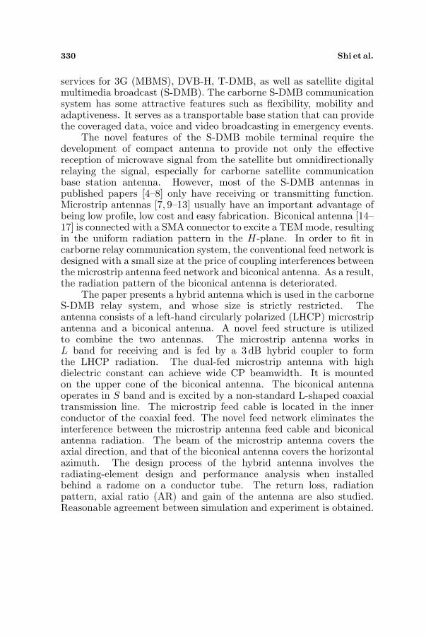
The configuration of the L band LHCP microstrip patch antenna isshown in Fig. 2. The patch is circular, and a 3 dB hybrid coupleris applied to a dual-orthogonal feed network. The diameter of theantenna D and the patch Da are 69 mm and 51mm, respectively. WideCP beamwidth can be obtained by using high relative permittivity.The circular patch antenna is made on a FR4 supporting substrate of
332 Shi et al.
(a) (b)
Figure 2. The configuration of the microstrip antenna (a) top view,(b) buttom view.
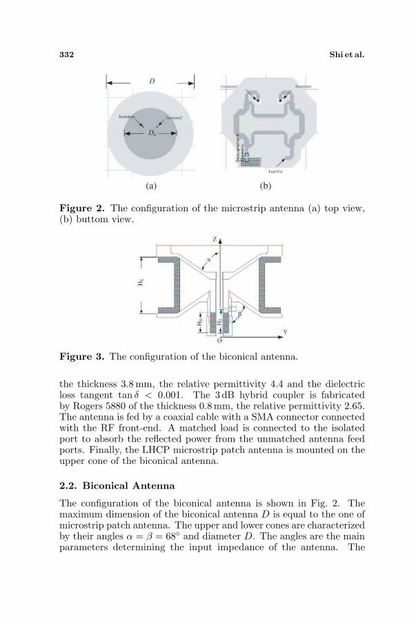
Figure 3. The configuration of the biconical antenna.
the thickness 3.8 mm, the relative permittivity 4.4 and the dielectricloss tangent tan δ < 0.001. The 3 dB hybrid coupler is fabricatedby Rogers 5880 of the thickness 0.8 mm, the relative permittivity 2.65.The antenna is fed by a coaxial cable with a SMA connector connectedwith the RF front-end. A matched load is connected to the isolatedport to absorb the reflected power from the unmatched antenna feedports. Finally, the LHCP microstrip patch antenna is mounted on theupper cone of the biconical antenna.
2.2. Biconical Antenna
The configuration of the biconical antenna is shown in Fig. 2. Themaximum dimension of the biconical antenna D is equal to the one ofmicrostrip patch antenna. The upper and lower cones are characterizedby their angles α = β = 68◦ and diameter D. The angles are the mainparameters determining the input impedance of the antenna. The
Progress In Electromagnetics Research, PIER 95, 2009 333
dielectric holding between the upper and lower cones is used to fixthem. The dielectric permittivity of the dielectric holding is εr = 2.2,and the height Hs is 40mm.
The feed network of the biconical antenna is an overmoded coaxialtransmission line which is excited by a terminal short-circuit probe. Ashort-circuit tuning is located at the bottom of coaxial to tune theimpedance matching. Due to compact size requirement, the bottompart of the coaxial feed is coated by dielectric, and the length of thedielectric rod is HD = 14 mm. The distance from the bottom of thecoaxial feed to the probe is HF = 19mm which is nearly λ/4. The Lband feed cable can be located in the inner conductor of the coaxialfeed to eliminate the crosstalk coupling interference.
3. PARAMETER ANALYSIS
Because the height of the hybrid antenna is limited strictly, overmodedcoaxial waveguide is continued via the transition into the biconicalwaveguide, and the other end must be terminated by an electric short.In that case, the biconical waveguide excites not only a TEM mode,but also TEm1 modes which affect the omnidirectional radiation.
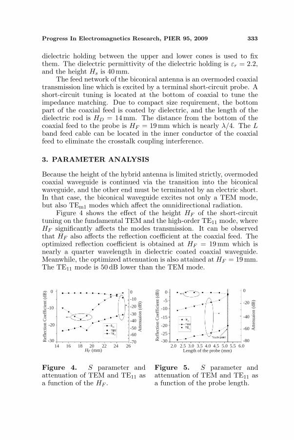
Figure 4 shows the effect of the height HF of the short-circuittuning on the fundamental TEM and the high-order TE11 mode, whereHF significantly affects the modes transmission. It can be observedthat HF also affects the reflection coefficient at the coaxial feed. Theoptimized reflection coefficient is obtained at HF = 19mm which isnearly a quarter wavelength in dielectric coated coaxial waveguide.Meanwhile, the optimized attenuation is also attained at HF = 19 mm.The TE11 mode is 50 dB lower than the TEM mode.
Ref
lect
ion
Coe
ffic
ient
(dB
) 0
-10
-20
-30
Atte
nuai
on (
dB)
0
-20
-50
-70
-10
-30
-40
-60
14 16 18 20 22 24 26HF (mm)
Figure 4. S parameter andattenuation of TEM and TE11 asa function of the HF .
Ref
lect
ion
Coe
ffic
ient
(dB
) 0
-10
-20
-30
Atte
nuai
on (
dB)
0
-20
-80
-40
-60
2.0 2.5 3.0 3.5 4.0 4.5 5.0Length of the probe (mm)
-5
-15
-25
5.5 6.0
Figure 5. S parameter andattenuation of TEM and TE11 asa function of the probe length.
334 Shi et al.
Figure 5 shows the effect of the length of the feed probe on theTEM and the TE11 modes. Results show that the length significantlyaffects the modes transmission. It can be observed that the lengthalso affects the reflection coefficient at the coaxial feed. The optimizedreflection coefficient is obtained when the feed probe connects to theinner conductor of the overmoded waveguide. The TE11 mode is 40 dBlower than the TEM mode.
4. EXPERIMENTAL RESULT AND DISCUSSION
In this section, the simulated and measured results of a manufacturedprototype antenna are presented.
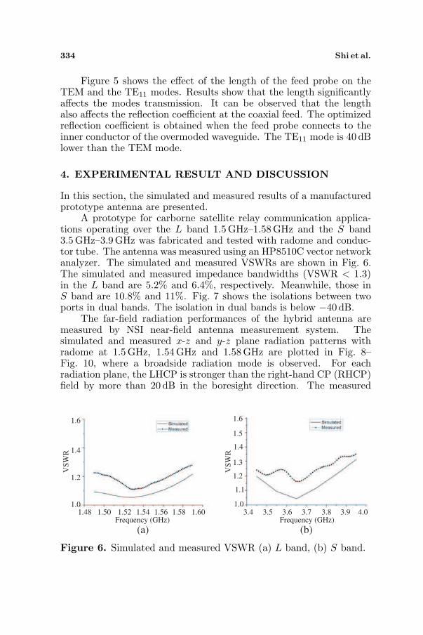
A prototype for carborne satellite relay communication applica-tions operating over the L band 1.5GHz–1.58 GHz and the S band3.5GHz–3.9GHz was fabricated and tested with radome and conduc-tor tube. The antenna was measured using an HP8510C vector networkanalyzer. The simulated and measured VSWRs are shown in Fig. 6.The simulated and measured impedance bandwidths (VSWR < 1.3)in the L band are 5.2% and 6.4%, respectively. Meanwhile, those inS band are 10.8% and 11%. Fig. 7 shows the isolations between twoports in dual bands. The isolation in dual bands is below −40 dB.
The far-field radiation performances of the hybrid antenna aremeasured by NSI near-field antenna measurement system. Thesimulated and measured x-z and y-z plane radiation patterns withradome at 1.5 GHz, 1.54 GHz and 1.58 GHz are plotted in Fig. 8–Fig. 10, where a broadside radiation mode is observed. For eachradiation plane, the LHCP is stronger than the right-hand CP (RHCP)field by more than 20 dB in the boresight direction. The measured
(a) (b)
VS
WR
1.6
1.2
1.48 1.50 1.52 1.54 1.58 1.60Frequency (GHz)
1.4
1.01.56
VS
WR
1.3
1.1
1.6
1.4
1.2
1.0
1.5
3.4 3.5 3.6 3.7 3.9 4.0Frequency (GHz)
3.8
Figure 6. Simulated and measured VSWR (a) L band, (b) S band.

Progress In Electromagnetics Research, PIER 95, 2009 335
(a) (b)
Isola
tion (
dB
)
-30
-40
-50
-60
1.50 1.55 1.60 1.65Frequency (GHz)
-35
-45
-55
1.70
-65
Isola
tion (
dB
)
-25
-35
-45
-55
3.4 3.5 3.6 3.7Frequency (GHz)
-30
-40
-50
3.8
-60
3.9 4.0
Figure 7. Simulated and measued isolation between two port (a) Lband, (b) S band.
(a) (b)
Figure 8. Simulated and measured normalized radiation patern at1.5GHz in (a) x-z plane, (b) y-z plane.
(a) (b)
Figure 9. Simulated and measured normalized radiation patern at1.54GHz in (a) x-z plane, (b) y-z plane.
336 Shi et al.
(a) (b)
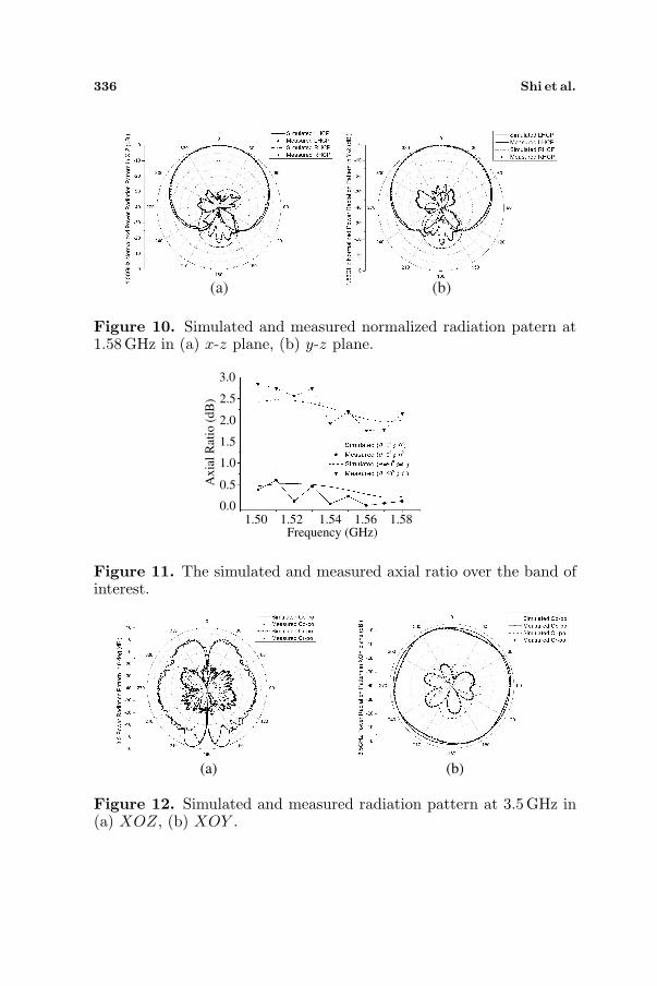
Figure 10. Simulated and measured normalized radiation patern at1.58GHz in (a) x-z plane, (b) y-z plane.
1.50 1.52 1.54 1.56 1.58Frequency (GHz)
Axia
l R
atio
(dB
)
0.0
0.5
1.0
1.5
2.0
2.5
3.0
Figure 11. The simulated and measured axial ratio over the band ofinterest.
(a) (b)
Figure 12. Simulated and measured radiation pattern at 3.5GHz in(a) XOZ, (b) XOY .

Progress In Electromagnetics Research, PIER 95, 2009 337
(a) (b)
Figure 13. Simulated and measured radiation pattern at 3.7GHz in(a) XOZ, (b) XOY .
(a) (b)
Figure 14. Simulated and measured radiation pattern at 3.9GHz in(a) XOZ, (b) XOY .
results are in good agreement with the simulated ones. Fig. 11 alsoshows the frequency response of AR results on the Z axis and in theθ = 60◦ direction. The ARs in both directions are below 3 dB in theoperating band. Accordingly, it is shown that a good CP performanceand a wide CP beamwidth are obtained.
Figures 12–14 show the co-polarization (Co-po) and cross-polarization (Cr-po) of the power gain radiation pattern with radomein XOZ plane and XOY plane at 3.5 GHz, 3.7 GHz and 3.9 GHz,respectively. Good omnidirectional radiation in the azimuthal planewith ripples less than 2 dB is obtained. For each radiation plane,good Cr-po radiation is observed. The Co-po is stronger than theCr-po field by more than 20 dB in the horizontal plane. The measuredresults are in good agreement with simulated ones. The error betweenthe simulated and measured results is mainly due to the fabrication
338 Shi et al.
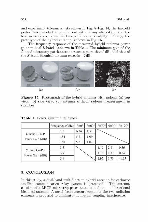
and experiment tolerances. As shown in Fig. 8–Fig. 14, the far-fieldperformance meets the requirement without any aberration, and thefeed network combines the two radiators successfully. Finally, theprototype of the hybrid antenna is shown in Fig. 15.
The frequency response of the measured hybrid antenna powergains in dual L bands is shown in Table 1. The minimum gain of theL band microstrip patch antenna reaches more than 0 dBi, and that ofthe S band biconical antenna exceeds −2 dBi.
(a) (b) (c)
Figure 15. Photograph of the hybrid antenna with radome (a) topview, (b) side view, (c) antenna without radome measurement inchamber.
Table 1. Power gain in dual bands.
Frequency (GHz) θ=0° θ=60° θ=70° θ=90° θ=120°
1.5 6.36 1.54
1.54 5.71 1.09 L Band LHCP
Power Gain (dBi) 1.58 5.31 1.02
3.5 1.19 2.81 0.56
3.7 1.16 1.87 0.84 S Band Co-Po
Power Gain (dBi) 3.9 1.95 1.78 −1.35
5. CONCLUSION
In this study, a dual-band multifunction hybrid antenna for carbornesatellite communication relay system is presented. The antennaconsists of a LHCP microstrip patch antenna and an omnidirectionalbiconical antenna. A novel feed structure combines the two radiationelements is proposed to eliminate the mutual coupling interference.

Progress In Electromagnetics Research, PIER 95, 2009 339
The simulated and measured results show reasonable agreement.A wide LHCP radiation beam and an omnidirectional radiation beamare obtained. The manufactured prototype antenna shows expectedresult in dual bands.
The proposed antenna is robust, simple in structure and easy tobe fabricated, so as to be potentially useful in a carborne satellitecommunication relay system.
REFERENCES
1. Grube, M., P. Siepen, C. Mittendorf, M. Boltz, and M. Srinivasan,“Applications of MPEG-4: Digital multimedia broadcasting,”IEEE Transactions on Consumer Electronics, Vol. 47, 474–484,2001.
2. Ha, V. H. S., C. Sung-Kyu, J. Jong-Gu, L. Geon-Hyoung,and S. Woo-Sung, “Portable receivers for digital multimediabroadcasting,” IEEE Transactions on Consumer Electronics,Vol. 50, 666–673, 2004.
3. Sammo, C., L. GwangSoon, B. Byungjun, Y. KyuTae, A. Chung-Hyun, L. Soo-In, and A. Chiteuk, “System and services ofterrestrial digital multimedia broadcasting (T-DMB),” IEEETransactions on Broadcasting, Vol. 53, 171–178, 2007.
4. Byungje, L., F. J. Harackiewicz, B. Jung, and P. Myun-Joo,“Cavity-backed slot antenna array for the repeater system of asatellite digital multimedia broadcasting service,” Antennas andWireless Propagation Letters, IEEE, Vol. 4, 389–392, 2005.
5. Hong Moon, H., A. Fedotov, A. Vishnevetsky, I. Drobnov,A. Ivanov, and A. Kozyrev, “S-band traveling wave ringantennas for cellular phones,” Antennas and Propagation SocietyInternational Symposium 2006, IEEE, 3119–3122, 2006.
6. Gyoo-Soo, C., L. Joong-Soo, and K. Min-Nyun, “A novel QHA forS-DMB applications,” Asia-Pacific Microwave Conference, 2007,1–3, 2007.
7. Jung-han, K., K. Joong-kwan, K. Yong-jin, and L. Hong-min, “High gain antenna using parasitic shorted annular patchstructure,” Asia-Pacific Microwave Conference, 2007, 1–4, 2007.
8. Gyoo-Soo, C., P. Young-Chul, L. Joong-Soo, and K. Min-Nyun,“Novel S-DMB antenna design using modified QHA,” Asia-PacificMicrowave Conference, 2006, 2056–2058, 2006.
9. Lee, K.-F., S. S. Yang, A. A. Kishk, and K.-M. Luk, “Designand study of wideband single feed circularly polarized microstrip

340 Shi et al.
antennas,” Progress In Electromagnetics Research, PIER 80, 45–61, 2008.
10. Kaya, A., “High gain rectangular broad band microstrip antennawith embedded negative capacitor and chip resistor,” Progress InElectromagnetics Research, PIER 78, 421–436, 2008.
11. Kumar, P., T. Chakravarty, G. Singh, S. Bhooshan, S. K. Khah,and A. De, “Numerical computation of resonant frequency of gapcoupled circular microstrip antennas,” Journal of ElectromagneticWaves and Applications, Vol. 21, No. 10, 1303–1311, 2007.
12. Ouyang, J., F. Yang, S. W. Yang, and Z. P. Nie, “Exact simulationmethod VSWIE +MLFMA for analysis radiation pattern ofprobe-feed conformal microstrip antennas and the applicationof synthesis radiation pattern of conformal array mountedon finite-length PEC circular cylinder with DEs,” Journal ofElectromagnetic Waves and Applications, Vol. 21, No. 14, 1995-2008, 2007.
13. Sim, C.-Y.-D. and B.-H. Yang, “A single layer dual-band CPmicrostrip antenna for GPS and DSRC applications,” Journal ofElectromagnetic Waves and Applications, Vol. 22, No. 4, 529–539,2008.
14. Black, D. N. and T. A. Brunasso, “An ultra-wideband biconeantenna,” The 2006 IEEE 2006 International Conference onUltra-wideband, 327–332, 2006.
15. McDonald, J. L. and D. S. Filipovic, “On the bandwidthof monocone antennas,” IEEE Transactions on Antennas andPropagation, Vol. 56, 1196–1201, 2008.
16. Sandler, S. S. and R. W. P. King, “Compact conical antennasfor wide-band coverage,” IEEE Transactions on Antennas andPropagation, Vol. 42, 436–439, 1994.
17. Ghosh, D., T. K. Sarkar, and E. L. Mokole, “Design of a wide-angle biconical antenna for wideband communications,” ProgressIn Electromagnetics Research B, Vol. 16, 229–245, 2009.