is 4907 (2004): method of testing timber connector joints
TRANSCRIPT

Disclosure to Promote the Right To Information
Whereas the Parliament of India has set out to provide a practical regime of right to information for citizens to secure access to information under the control of public authorities, in order to promote transparency and accountability in the working of every public authority, and whereas the attached publication of the Bureau of Indian Standards is of particular interest to the public, particularly disadvantaged communities and those engaged in the pursuit of education and knowledge, the attached public safety standard is made available to promote the timely dissemination of this information in an accurate manner to the public.
इंटरनेट मानक
“!ान $ एक न' भारत का +नम-ण”Satyanarayan Gangaram Pitroda
“Invent a New India Using Knowledge”
“प0रा1 को छोड न' 5 तरफ”Jawaharlal Nehru
“Step Out From the Old to the New”
“जान1 का अ+धकार, जी1 का अ+धकार”Mazdoor Kisan Shakti Sangathan
“The Right to Information, The Right to Live”
“!ान एक ऐसा खजाना > जो कभी च0राया नहB जा सकता है”Bhartṛhari—Nītiśatakam
“Knowledge is such a treasure which cannot be stolen”
“Invent a New India Using Knowledge”
है”ह”ह
IS 4907 (2004): Method of testing timber connector joints[CED 9: Timber and Timber Stores]


m? +i’hJmCita$m%l-mawl?.( Wd7 pa%w7)
Indian Standard
METHOD OF TESTING TIMBER CONNECTOR JOINTS
( First Revision)
ICS 19.020; 2 1.060; 79.040
0 BIS 2004
BUREAU OF INDIAN STANDARDSMANAK BHAVAN, 9 BAHADUR SHAH ZAFAR MARG
NEW DELHI 110002
August 2004 Price Group 3

Timber and Timber Stores Sectional Committee, CED 9
FOREWORD
This Indian Standard ( First Revision ) was adopted by the Bureau of Indian Standards, after the draft finalizedby the Timber and Timber Stores Sectional Committee had been approved by the Civil Engineering DivisionCouncil.
One of the significant advances in timber design has resulted from the improvements in joints through thedevelopment and incorporation of metal connectors. The timber connectors which may have a variety offorms; such as split rings, toothed rings, clamping plates, shear plates and claw plates depending on their specificdesign functions have been extensively used in foreign countries. Due to the non-availability of patentedconnectors in India, these are not very popular among engineers and builders in this country. However,improvised metallic rings cut from mild steel pipes are gradually beginning to be used for load transfer instructures in this country also besides the other types, wherein a split circular band of steel is placed in thegroove cut into the contact faces of the timber members to be joined, the assembly of members being heldtogether with a connecting bolt. The main function of these connectors is to efficiently transfer stress from onemember to another. Tests on timber connector are required to be done so as to obtain design data for their use instructural applications. This standard provides suitable procedures for evaluating the strength and rigidityof connectors in timber joints. The testing serves both as basis for developing design criteria and orinvestigating the effect of various factors such as thickness and width of members, end and edge margins,spacing and moisture contents, etc, on the strength and efficiency of the connector itself under three groups ofspecies of wood.
This standard was first published in 1968. In this revision certain additions and amendments have beenmade in light of experience gained with testing of improvised metallic ring connector joints. The conceptof joint factor and the speed of machine is revised. In the preparation of this standard considerable assistancehas been rendered by Forest Research Institute, Debra Dun.
In the formulation of this standard, due weightage has been derived to international co-ordinationamong the standards and practices prevailing in different countries in addition to relating to the practices in thefield in this country.
In reporting the result of a test or analysis made in accordance with this standard, if the final value, observedor calculated, is to be rounded off, it shall be done in accordance with IS 2 : 1960 ‘Rules for rounding offnumerical values ( revised)’.

IS 4907:2004
Indian Standard
METHOD OF TESTING TIMBER CONNECTOR JOINTS
(’First Revision)
1 SCOPE
This standard deals with the methods of testingtimber joints made by using timber connectors.The details of fabrication of such joints, toolsneeded and the designing methods have not beenincluded in this standard and which may formseparate code of practice on ‘Metallic rings connectorsjointed timber construction’ to be brought out.
2 TERMINOLOGY
For the purpose of this standard, the definitionsgiven in 1S707:1976 ‘Glossary of terms applicableto timber technology and utilization ( secondrevision )’ and the following shall apply.
2.1 Timber Connectors — Rings, grids, plates ofdowels of metal or wood set in adjoining members,usually in pre-cut grooves, holes of recesses, to fastenthe members together in conjunction with bolt.
2.2 End Distance — The distance measured parallelto the grain of the timber from the centre of theconnector to the closest end of the member ( see A inFig. 1 ). When the end of the member is not squareout that is for sloping end cut, maintain the edgedistance as shown in Fig. 1.
2.2.1 Loaded-End or Compression-End Distance
The distance measured from the centre of theconnector to the end towards which the loadinduced by the connector acts.
2.2.2 Unloaded-End Distance
The end distance opposite to the loaded end.
--i’t-- 1
2.3 Edge Distance
The distance measured perpendicular to the grainfrom the centre of the connector to the edge of themember ( see B and C in Fig. 2 ).
2.3.1 Loaded-End or Compression-Edge Distance
The distance measured from the centre of theconnector to the edge towards which the loadinduced by the connector acts ( see C in Fig. 2 ).
2.3.2 Unloaded-Edge Distance
The edge distance opposite to the loaded edge ( seeBin Fig. 2).
2.4 Connector Axis ( R )
The distance measured between centres ofadjacent connectors ( see Fig. 2 ) when more thanone connector is used in the same contact face of-amember in a joint. This is also known as spacing ofconnector.
2.5 Connector Data
The data covers recommended dimensions ofthe connectors, minimum timber sizes, bolt and bolt-hole diameters, washer sizes and similar other self-explanatory information which shaIl be required foruse of the particular .connector in any design.
2.6 Direction of Load
Unless otherwise specifically stated, direction ofload in any joint is the same as the direction of axisor grain of the member on which the load is initiallyapplied.
‘t-1 I
EDGE DISTANCE‘CONNECTORS TO BE MAINTAINED
NOTE — In no case shall the perpendicular distance from centre of connector to sloping end cut of a member be lessthan the required edge distance.
FIG. 1 ENDDISTANCE
1

IS 4907:2004
I rCONNECTORSt 1 l\
B
t
t-
-F-
+R-+ 1FiG.2 EDGEDISTANCEAN~SPACING
2.7 Direction of Grain
Unless otherwise specifically stated, direction of grainin any joint is the direction of grain of the member towhich the load is finally transmitted through theconnectors.
2.8 Angle Between Grain and Load (0)
The acute angle between the direction of load,and the direction of grain in a particular member( see Fig. 3).
CONNECTOR Y
FIG.3 ANGLEOFLOAD-TO-GRAIN
2.9 Central Member(s)
Member(s) through which the load is initiallyapplied so that the same maybe transmitted throughthe connectors.
2.10 Joint Factor
It is the total load developed by the joint expressedas a percentage of the full load which the mainunjointed central member ( primary member ) maysustain ( see Annex A ).
2.11 Side Member(s)
Member(s) to which thethrough the connectors.
2.12 Specified Slip
load is finally transmitted
The total slip at which the joint shall be assured tocarry maximum load.
3 TESTING PROCEDURES
3.1 For purposes of comparison, connectors shallbe tested on three groups of species as following:
a) Group A : Species which differ from ‘sal’by* 30 percent in compressive
strength.
b) Group B : Species which differ from ‘teak’by *30 percent in compressivestrength.
c) Group C : Species which differ ffom ‘chir’by +30 percent in compressivestrength.
3.2 All timber members used shall be at a12 + 1 percent of moisture content in the drycondition or at well above the fibre-saturation-pointin the green condition.
3.3 The connector shall fit singly in precutgrooves and shall be so placed as to correspondto the correct position in any designed joint. Whereno such pre-designed joint is under consideration,the loaded-edge distance shall be not less than thediameter of the connector and the end distanceshall be not less than 1.75 times its diameter on theloaded side. In case the connector is not circular, thelimiting dimension shall be the full dimension ofthe connector in the direction of measurement of theend and edge distance respectively.
3.4 Unless otherwise required for specificpurpose, all tests shall be made on three-member jointswith two similar connectors. In the three-memberioints each side member shall be of half the thicknessif the central member and the central member shallbe at least twice the depth ( or generally known aswidth ) of the connector, exception for split rings wheneach side member shall be of 2/3 the thickness ofcentral member. The general dimensions andarrangements are shown in Fig. 4A and Fig. 4B.
3.5 At least five specimens should be tested separatelyfor loadings in the parallel and in the perpendiculardirections of grain as shown in Fig. 4A and Fig. 4B.As and when required, a set of five tests maybe doneat intermediate angles by providing suitable supportsfor the pieces under test or preferably in appropriatejigs made for the purpose. Test the connector jointsas soon after assembly as possible.
3.6 The load shall be applied to the central memberin such a manner that the same is parallel to thegrain of the member. Application of load through ahemi-spherical loading head is recommended toensure proper alignment of joint members.
3,6.1 Rate of Loading
The load shall be applied continuously during thetest to cause the movable head of the testing machineto travel at a rate of 0.6 mm/min so as to produce aconstant rate of strain. The testing speed of themachine actually adopted shall be recorded on thedata sheet.
2

3.7 The joint shall be initially loaded slowly toabout 200 kg and load released to ensure any initialset of connector in the joint. Thereafter the loadshall be applied at suitable load intervals in such away as to produce a constant rate of strain. The slipbetween the members shall be measured by themovement of the straining head of the machine atsuitable load-interval (to permit feasibility of recordingthe readings ) with dial gauge graduated to 0.02 mmuntil maximum load is reached and/or the deflectioncontinues without increase of load. Any otheralternative/suitable device could also be used formeasuring slip. A load-slip curve shall be drawn fromwhich the load and slip at proportional limit shall beevaluated. All the data observed and calculated shallbe recorded as given in Annex A. A sketch of the
P
IS 4907:2004
connector and a design of the joint shall also be attachedto each data sheet indicating the original defects andfinal failure.
3.7.1 The slip in the joint shall be measured from thebeginning of the application of load and at sufficientlyfrequent load-intervals to permit drawing of anaccurate load-slip curve.
3.8 Additional information about the connectors asdescribed in Annex B shall be obtained whenevernecessary and special tests designed for obtainingsuch information.
3.9 Testing of multiple connectors shall be inaccordance with the provisions given in Annex C.
1
+
(/ ‘~+,\\\ //
——.—-—-
+--—---b---+
~=jc,b<2x.c~l.75x,d =Ze,e<tmdf=zc
4A Strength Test Parallel to Grain
+-b-+P1
a=3b, b<2x, c=l.lb, d= 2eande<t
4B Strength Test Perpendicular to Grain
FIG.4 STRENGTHTESTOFCONNECTORSPARALLELANDPERPENDICULARTOGRAINS
3
IS 4907:2004
ProjectNo.:
Consignment No.:
Laboratory No. :
Mark :
Species :
From :
Machine :
Speed of Machine :
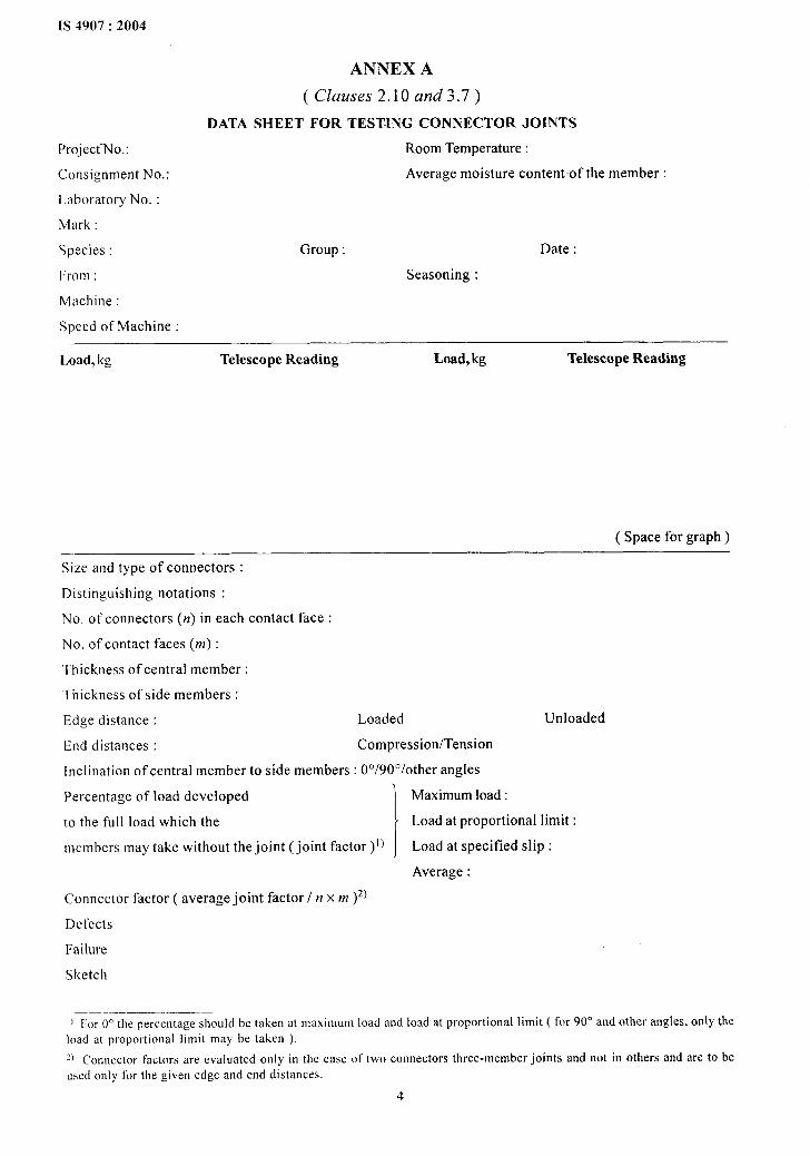
ANNEX A
( Clauses 2.10 and 3.7)
DATA SHEET FOR TESTING CONNECTOR JOINTS
Room Temperature:
Average moisture content of the member :
Group: Date :
Seasoning :
Load, kg Telescope Reading Load, kg Telescope Reading
( Space for graph)
Size and type of connectors :
Distinguishing notations :
No. of-connectors (n) in each contact face :
No. of contact faces (m) :
Thickness of central member :
Thickness of side members :
Edge distance : Loaded Unloaded
End distances : Compression/Tension
inclination of central member to side members : 00/900/other angles
Percentage of load developed
1
Maximum load:
to the full load which the Load at proportional limit :
members may takewithout the joint (joint factor )1) Load at specified slip:
Average :
Connector factor ( average joint factor/n x m )2)
Defects
Failure
Sketch
—.—.——I)For~0thepercentage~houldbct~k~~at,naxilllL1lllloadandloadatproportionallimit(for 90° and other angles. only the
load at proportional limit may be taken ).
~) Corlllector factors are ~valuated OIIIYill the case of two connectors three-member joints and not in others and are to be
used only for the given edge and end distances.
4

IS 4907:2004
ANNEX B
( Clause 3.8)
ADDITIONAL DATA REGARDING CONNECTORS
B-1 MINIMUM AND MAXIMUM END ANDEDGE DISTANCES
For each type of connector and for any given loadwhich is usually the permissible working load, themaximum and the minimum values of loaded edgedistances and the end distances for tension andcompression may be evaluated separately byexperiments.
B-2 EDGE-DISTANCE CHART
The percentage of full load at various edge distancesand for various inclinations of load-to-grainrepresented graphically is known as edge-distancechart. This chart is a useful additional data for theconnector. It may be seen from the chart whenprepared that the relationship between percentages
of full load and edge distances is linear and separatefor different angles.
B-3 END-DISTANCE CHART
The percentage of full load at various-end distancesand for various inclinations of load-to-grainrepresented graphically is known as end-distancechart. These charts when prepared differ forcompression and tension separately, and form usefuladditional data for the connectors.
B-4 SPACING CHART
For use in the design of multiple connectors, thedata on minimum connector spacing for specificpercentages of full loads in the 0° and 90° joints inthe case of two connectors shall be a useful informationfrom which spacing charts may be prepared.
ANNEX C
( Clause 3.9)
NOTES FOR USING CONNECTORS IN VARIOUS STRUCTURES
C-1 ALLOWABLE LOADS
Allowable loads for any joint using connectorsshall be calculated by multiplying connector factor,number of connectors in the contact faces and theworking loads for the species or group of species underconsideration.
C-2 DEVIATION FROM ALLOWABLE LOADS
Deviation from allowable loads shall be in accordancewith the following factors:
a) When allowable load is reduced due toreduced edge distance and end distance orspacing, the reduced allowable load for eachshall be determined separately. The “lowestallowable load so determined for any oneconnector shall apply to this connector andall other connectors resisting a common forcein a joint.
b) Reductions in load for edge distances, enddistances, and spacing are not additive butare co-incident.
c) Loads reduced because of thickness of
members do not permit any reduction in edgedistances, end distances or spacing withoutfurther reduction of load and conversely, loadsreduced for edge distances, end distances,or spacing do not permit reduction of thethickness.
C-3 MULTIPLE CONNECTORS
When more than one connector is used in the samecontact face, their number, location, and spacing shallbe in accordance with the following factors:
a) All connectors are so placed that as far aspossible they are symmetrical on the face ofcontact subject to the condition that all therequired minimum edge distances, enddistances, and end spacing are satisfied. Thearrangement is determined by the minimumspacing permitted and maximum spacingavailable.
b) The ratio of connectors used to connectorsrequired shall be not more than 2.
c) All connectors and bolts shall be of the samesize and shape through out the design and
5

IS 4907:2004
each component used shall be of the samematerial.
d) The connectors shall be so placed that theangle of resultant load-to-grain shall be morethan 45° so as to get the best performanceof the connectors and that all loads orcomponents thereof shall act in the samedirection on all faces.
e) The maximum allowable load shall be thesummation or the allowable loads for eachconnector used, provided, there are not morethan three connectors on each contact face.For each additional connector acceptedpercentage ( which is usually one-third ofthe allowable load of the same) shall be takenfor calculation of the total load.
~ The maximum connector spacing(R) at anyangle of loading ( O) is given by:
A rCONNECTOR
R.AB
~A2sin20 + B2 COS2(8)
whereA=
B=
minimum connector spacing for the 0°loading, and
minimum connector spacing for the 90°loading.
g) The location of the connectors is determinedby the intercept of the diameter of the ellipsewhose axis in the direction of grain is equalto A and in the perpendicular direction is equalto B.
NOTE — In the case of two connectors in the sameface placed in accordance with the above formula, thedirection of load coincides with the direction of connectoraxis but in the case of more than two, the connectoraxes make different angles with the direction of grainas shown in Fig. 5.
ETA--I
FIG.5 LOCATIONOFCONNECTORS
6

f
Bureau of Indian Standards
B[S is a statutory institution established under the Bureau of Indian Standards Act, 1986 to promoteharmonious development of the activities of standardization, marking and quality certification df goods andattending to connected matters in the country.
Copyright
BIS has the copyright of all its publications. No part of these publications may be reproduced in any formwithout the prior permission in writing of BIS. This does not preclude the free use, in the course of implementingthe standard, of necessary details, such.as symbols and sizes, type or grade designations. Enquiries relatingto copyright be addressed to the Director (Publications), BIS.
Review of lndiau Standards
Amendments are issued to standards as the need arises on the basis of comments. Standards are also reviewadperiodically; a standard along with amendments is reaffirmed when such review indicates that no changes areneeded; if the review indicates that changes are needed, it is taken up for revision. Users of Indian Standardsshould ascertain that they are in possession of the latest amendments or edition by referring to the latest issueof ‘BIS Catalogue’ and ‘Standards : Monthly Additions’.
This Indian Standard has been developed from Doc : No. CED9( 5913).
Amendments Issued Since Publication
Amend No. Date of Issue Text Affected
BUREAU OF INDIAN STANDARDS
Headquarters:
Manak Bhavan, 9 Bahadur Shah Zafar Marg, New Delhi 110002Telephones: 23230131,23233375,2323 9402 Website: www. bis.org. in
Regional Offices : Telephones
Central :
Eastern :
Northern :
Southern:
Western :
Manak Bhavan, 9 Bahadur Shah Zafar Marg
{
23237617NEW DELHI 110002 23233841
l/14C. 1.T. Scheme VI IM, V. l. P. Road, Kankurgachi
{
2337%499,23378561KOLKATA 700054 23378626,23379120
SCO 335-336, Sector 34-A, CHANDIGARH 160022
{
26038432609285
C. I. T. Campus, IV Cross Road, CHENNAI 600113
{
22541216,2254 ‘144222542519,22542315
Manakalaya, E9 MlDC, Marol, Andheri (East) ( 28329295,28327858MCJMBAi400 093 ~ 28327891:28327892
Branches : AHMEDABAD. BANGALORE. BHOPAL. BHUBANESHWAR. COIMBATORE.FARIDABAD. GHAZIABAD. GUWAHATI. HYDERABAD. JAIPUR. KANPUR.LUCKNOW. NAGPUR. NALAGARH. PATNA. PUNE. RAJKOT. THIRUVANANTHAPURAM.VISAKHAPATNAM.
PrintedIt New [ndio Printing Press, Khtqa, India