irse news news 19… · · 2016-09-03irse news | issue 194 ... chandrika prasad ... installation...
TRANSCRIPT

IRSE NEWS ISSUE 194 NOVEMBER 2013

Front Cover: This Indian Railways (IR) 100mph (160 km/h) four-axle passenger electric locomotive employs three-phase technology and is used on IR's heaviest and fastest passenger services around the country on it's 5ft 6in (1676mm) gauge network. This particular locomotive is seen here at arriving at New Delhi station hauling the Shatabdi Express during the IRSE Convention to India on Thursday 28th October 2010. Photo: Ian James Allison
TENCONI steel construction department has a reputation of excellence also for the manufacture of special steel hollow sleepers, low friction slide chairs, insulated base plates and many other railway products.
TENCONI SAMechanical workshopCH-6780 Airolo
For more information contact:Sales manager: Fabrizio LucchiniTel.: +41 91 873 30 00Mobile: +41 79 435 59 84E-Mail: [email protected]
Manufacture of Insulated Rail Jointsin Hardomid for Railways and of special hollow sleepersTENCONI plastic division is the only manufacturer of the high quality insulatedrail joints also called "BENKLER" joints. The pieces are produced also in smallbatches, according to customers' specifications and needs.
TEN 01/10 Annuncio 190x130 mm.qxd:01/10 Tenconi Annuncio 190x130 mm 8.6.2010 15:20 Pagina 1

NO
T FO
R RE
-PRI
NTI
NG
©
IRSE NEWS | ISSUE 194 | NOVEMBER 2013
IRSE NEWS is published monthly by the Institution of Railway Signal Engineers (IRSE). The IRSE is not as a body responsible for the opinions expressed in IRSE NEWS.
© Copyright 2013, IRSE. All rights reserved. No part of this publication may be reproduced, stored in a retrieval system, or transmitted in any form or by any means without the permission in writing of the publisher. Copying of articles is not permitted except for personal and internal use. Multiple copying of the content of this publication without permission is always illegal.
Editor Ian J Allison 102 Beacon Road, Loughborough, LE11 2BH, UK Tel: +44 (0) 7794 879286 e-mail: [email protected]
Deputy Editor Tony Rowbotham 36 Burston Drive, Park Street, St Albans, AL2 2HP, UK e-mail: [email protected]
Assistant Editors Harry Ostrofsky (Africa) e-mail: [email protected] Tony Howker (Australasia) e-mail: [email protected] David Thurston (N. America) e-mail: [email protected] Buddhadev Dutta Chowdhury (Asia) e-mail: [email protected] Wim Coenraad (Europe) e-mail: [email protected] Priyank Patel (Younger Members) e-mail: [email protected]
Contributions Articles of a newsworthy or technical nature are always welcome for IRSE NEWS. Members should forward their contributions to one of the Editors listed above.
Advertising For advertising rates and deadlines call Andrew Walker at DVV Media Tel: +44 (0)208 652 5214 e-mail: [email protected]
Advertisements are accepted on the basis that the advertiser and agency (if any) warrant that the contents are true and correct in all respects.
Web Site For up to date information about the Institution or its activities, or to download a membership application form, log on to the IRSE Web Site: www.irse.org
London Office IRSE, 4th Floor, 1 Birdcage Walk, Westminster, London, SW1H 9JJ, United Kingdom
Enquiries
MEMBERSHIP OR OF A GENERAL NATURE Tel: +44 (0)20 7808 1180 Fax: +44 (0)20 7808 1196 e-mail: [email protected]
PROFESSIONAL DEVELOPMENT Tel: +44 (0)20 7808 1186 e-mail: [email protected]
LICENSING Tel: +44 (0)20 7808 1190 e-mail: [email protected]
1
www.facebook.com/IRSEUK www.facebook.com/IRSEOz www.facebook.com/ian.allison
IN THIS ISSUE Page The London November Paper, ‘Beyond ETCS - Interoperable Interfaces and More’ was not available when we went to press. This will be published in a later Issue of IRSE NEWS.
Shaping the future of transportation in Malaysia 2 Zulkifli Md. Hussain and Polsamat Prajakfueangfu
Framing & Compliance of Technical Specifications - A Case Study Using Telecommunication Cables in an Underground MRTS Project 4 Yog Raj Bhardwaj
The Rise of the Electronic Interlocking in India 8 Chandrika Prasad
Avoiding the Butterfly Effect of Failures in Railway Signalling and Telecommunication Systems 10 Wim Coenraad for the IRSE International Technical Committee
Train Integrity is the Responsibility of the Railway Undertaking 14 Ian Mitchell for the IRSE International Technical Committee
Products of the Imagination 15 Mike Mustard
Industry News 18
IRSE Matters 20 Signalling Maintenance and Inspection Workshop
Feedback 21
Book Reviews: Signalboxes by Michael A Vanns 22
Reminders and Announcements 24
Recruitment 19 and 25
Membership Matters 26
NEWS VIEW 194 A polite request please?
Front Cover: This Indian Railways (IR) 100mph (160 km/h) four-axle passenger electric locomotive employs three-phase technology and is used on IR's heaviest and fastest passenger services around the country on it's 5ft 6in (1676mm) gauge network. This particular locomotive is seen here at arriving at New Delhi station hauling the Shatabdi Express during the IRSE Convention to India on Thursday 28th October 2010. Photo: Ian James Allison
Well, yet another enjoyable IRSE Convention has been had by the many who attended this year in Sweden and Denmark during September. Whilst the Convention report will not begin to appear until the end of this year, the members and guests who attended this fine event are encouraged to forward their pictures for potential inclusion with reports from both older and younger members of the Institution who attended and took the time to record the activities they undertook during this particular week. Please feel free to forward your pictures in a JPEG format with relevant captions and the photographers name to [email protected] before 10/11/13 for possible inclusion.
and now for something completely different As you will be aware, this magazine is coming up to issue 200. In order to prepare for this forthcoming issue, some planning is taking place. We are looking for pictures related to the speed of 200 km/h and to be able to borrow or be loaned ERTMS lineside marker boards for a potential photo shoot. If you or your company can assist with either or both of these requests, we would very much appreciate if you can make contact with us at [email protected] before the end of November 2013.
and finally This magazine continues to progress and move forward as a result of the contributions from its members and the signalling and telecommunications industry world-wide. The editorial team around the world looks forward to your contributions and feedback in order to continue to improve this publication.
The Editor

NOT FOR RE-PRINTING
©
IRSE NEWS | ISSUE 194 | NOVEMBER 2013 2
CBTC IN MALAYSIA
Greater Kuala Lumpur/Klang Valley is one of Malaysia’s National Key Economic Areas and an important part of the country’s Economic Transformation Programme (ETP). Propelling Malaysia towards developed nation status, the programme is transforming Malaysia’s capital into one of the world’s most livable cities and a leading economic hub.
With major commercial and property development underway, such as the new Kuala Lumpur International Financial District (KLIFD), enhanced rail systems are required. These will provide good access to the city centre, increased connectivity across the Klang Valley and ensure sustainable development.
Part of this transformation, the Klang Valley Mass Rapid Transit (KVMRT) project for the construction of three new urban mass transit lines was approved by the Government of Malaysia in 2010. Designed to integrate with existing light-, mono-, commuter and airport rail systems, the new lines will significantly increase the coverage of rail transport in the Greater Kuala Lumpur area, where the target is that 50% of all travel will be by public transport by 2020.
In September 2012, the Mass Rapid Transit Corporation Sdn Bhd (MRT Corp) awarded Bombardier the five-year signalling contract for the first MRT line. Valued at approximately 28 million Malaysian ringgit or 71 million euro, Bombardier is delivering its advanced, globally-proven CITYFLO 650 Communications-Based Train Control (CBTC) solution for driverless operation with the project delivery partner MMC-Gamuda JV for the Sungai Buloh-Kajang (SBK) Line.
As part of the contract, Bombardier and Global Rail will also contribute to Malaysia’s rail industry by develop-ing local expertise in a joint programme of activities.
Shaping the future of transportation in Malaysia By Zulkifli Md. Hussain, Global Rail (Malaysia)
and Polsamat Prajakfueangfu, Bombardier (Thailand)
CBTC TECHNOLOGY TO SOLVE THE CAPACITY CHALLENGE Located in the north-west of Kuala Lumpur and running through the city centre, the SBK line will serve a corridor with an estimated 1.2 million residents in the urban and suburban areas of Klang Valley and has an expected daily ridership of 400 000 passengers. CBTC technology was chosen due to the capacity and safety benefits that the technology brings to such a high density application as well as its proven global record.
System Architecture The system to be delivered is a highly-proven, automatic train control solution designed for complex, high-capacity metros and monorails as well as automated people movers. Based on a true moving block CBTC system, it uses bi-directional radio communication between trains and wayside equipment. It is developed to support a wide range of automation; including semi- automated (Grade of Automation Level 2, GoA2), driverless (GoA3) and unattended (GoA4), as well as manual driving with Automatic Train Protection (ATP) system protection as a fallback solution.
Comprising various subsystems, the functional and modular hardware and software is configured in hot-standby redundant architectures, including the radio components, to ensure high system availability. The typical CBTC system has four main system levels:
Onboard equipment: vehicle Automatic Train Control (ATC) including both vehicle ATP and ATO subsystems;
Trackside equipment such as point machines, axle counters, and radio equipment.;
Safety and Control (ATP/Interlocking);
Supervision and monitoring (Automatic Train Supervision, ATS). Within this architecture, the onboard equipment accurately tracks the location of the train. The trackside equipment keeps track of all train locations, the status of point machines, routes, etc. and provides movement authority to the trains over the radio. Wayside equipment is connected using a Data Transmission System (DTS), which provides a redundant, fault-tolerant communication network.
Safety and Capacity for the Klang Valley Scope of delivery for the SBK Line comprises the design, supply, installation and commissioning of the rail control solution for 51 km of track, which includes 31 elevated and underground stations, and onboard equipment for 58 trains plus a further 16 maintenance vehicles.
The system will operate in GoA4 (fully unattended and driverless) and will also support mixed mode operation. Trains without CBTC can be detected via axle counters and run in accordance with optical signals, whilst CBTC-equipped trains will run at a minimum distance according to the moving block principles.
The moving block and fast train-to-wayside radio communication will allow trains to operate with very short headways also ensuring maximised capacity. The system has been designed for an operational headway of 80 seconds including turnback between trains. Automation systems such KAJANG
The SG Buloh - Kajang MRT Line
SG BULOH Gombak
Cheras
City Centre
Ampang
Bandar Tun Hussein Onn
Putra Heights
Kelana Jaya
Sg Buloh - Kajang Line
Kelana Jaya Line (LRT)
Ampang Line (LRT)
Sri Petaling
Mutiara Damansara
Bukit Damansara
Bandar Utama Kota Damansara
Sentul
Taman Tun Dr Ismail
1

NOT FOR RE-PRINTING
©
NOT FOR RE-PRINTING
©
IRSE NEWS | ISSUE 194 | NOVEMBER 2013 3
as dispatching, route setting, and automatic door controls will allow the trains to run punctually.
Another benefit of moving block CBTC system based on radio communication is the reduction in trackside equipment and associated maintenance expenditure. The secondary train detection system features longer axle counter sections – typically only one block between stations -- and the quantity of optical signals is reduced. Maintenance costs are also minimised as the system utilises modern Commercial-Off-The-Shelf (COTS) electronics that facilitates minimum preventive maintenance.
Inconsistent performance can be analysed by the advanced diagnostic system. A dedicated monitoring system will allow the early detection of potential failures, so maximizing availability. Additionally, all sub-systems are fully redundant, enabling operation with the backup unit during failure and repairs, thereby maximising operational availability and ensuring passengers are not affected by failures.
An Automatic Train Regulation (ATR) feature saves energy when the timetable has specified a longer than minimum run time for the purposes of schedule adherence, de-bunching, or conflict avoidance. The ATR then selects the minimum train performance level that will result in the train arriving at the next station at the appropriate time.
Building Local Expertise To ensure the sustainability of the Malaysian railway industry in the future, development of technology plus locally-based expertise is critical.
As part of the contract, Bombardier and Global Rail have partnered to support the development of new skills. This will be achieved through joint developments during the project, such as on-the-job training and IRSE licensing of engineers and technicians in Malaysia. The programme to bring long term benefits to the industry will be supervised by MiGHT, the Malaysian Industry-Government Group for High Technology.
This collaboration will not only benefit young graduates, engineers, and technicians, but also the country’s economy. More employment will be created as well as an industry capable of maintaining the advanced technology being deployed on the Malaysian railways, and exporting technology and services to neighbouring countries.
Partnership for the Future Phase One of the KV MRT SBK Line (Sungai Buloh to Semantan) is planned to commence operations by December 2016. Phase Two (Semantan to Kajang) will become fully operational by July 2017. The further two lines of the MRT will be constructed after completion of further studies by Malaysia’s Public Transport Commission (SPAD)
The selection of CBTC for the new Klang Valley MRT will shape the future of mobility in Malaysia, ensuring the optimal delivery of high capacity and safety in its application. Additionally, the cooperation between Bombardier and Global Rail will contribute to the sustainable development of local expertise, meeting the current and future need of the industry.
2
3 4
Fig 1: SBK Line
Fig 2: Klang Valley onboard architecture
Fig 3: Typical Wayside architecture
Fig 4: Klang Valley architecture

NOT FOR RE-PRINTING
©
IRSE NEWS | ISSUE 194 | NOVEMBER 2013 4
FRAMING TECHNICAL SPECIFICATIONS
This paper is a sequel to article “Use of Telecomm. Cables in underground Metro systems: Fire Properties: An informative study” published in IRSE News – Issue 153, February 2010.
Using a real life experience from a Mass Rapid Transit System project, the author through this paper has tried to bring out fallacies in practices presently being followed in various stages of a project, right from framing of Technical/Functional specifications to approval of design/material/equipment . He has also suggested remedies to overcome these shortcomings.
BACKGROUND Framing of Technical Specifications (TS) for any system involves defining technical & functional requirements along with compliance to a number of standards. In addition, TS also includes specific provisions from various standards. A typical TS therefore is a mix of functional requirements, general compliance to various standards and special mention of clauses extracted from various standards. This methodology of framing the TS ensures that the TS includes compliance to best of all standards along with technical and functional requirements of the system.
By using above methodology , both the consultant and the customer have a sense of satisfaction that they would get the best of the product available without realising its cost and other related repercussions as brought out in this case study.
INTRODUCTION Cables for various applications are an important component of any metro project more so in an underground project. However, in this paper , cables used for telecommunication applications shall be discussed.
Major Telecomms Systems in a typical Metro System:
PABX System; • CCTV System;
Master Clock System; • Emergency Radio System;
Digital Transmission System (DTS);
Public Announcement System (PAS);
Public Information & Display System (PIDS);
Central Fault Reporting System (CFRS).
Various Types of Cables Used for the Working of the above Systems:
Category Cables (CAT), pertaining to Data (Local Area Network) cables;
Audio Cables; • Telephone Cables;
Power Cables; • Optical Fibre Cables;
Leaky (Radiating) Coaxial Cables;
Feeder Coaxial cables.
TECHNICAL SPECIFICATIONS for Various Systems in a MRTS Project Inter-Alia Including Following Provisions Pertaining to Cables
General Requirements The Ethernet cable shall comply with relevant NFPA 130
requirements using fire resistant and Shielded Twisted-Pair cables (STP) CAT 6 cable, as a minimum;
The PAS cables shall be fire resistant Low Smoke Zero Halogen, in order to maintain the circuit integrity in case of fire;
All other cables shall be manufactured from fire resistant or retardant, low smoke and halogen free materials complying with NFPA 130 requirements.
Requirements Pertaining to PA Cables The loudspeaker cables of the PAS shall be continuously
monitored for short circuit, impedance and earth faults from the PAS management system;
All cablings and wiring inclusive of loudspeaker supply circuit cabling and the Fire Detection and Prevention System to PAS interconnections shall be low-smoke, low fume, halogen free and fire resistance type complying with BS 6387: 1994 Categories C, W and Z to achieve the optimum fire performance level;
All control and audio cables shall be twisted pair overall screened cables;
The screened twisted pair audio cables for loudspeaker distribution lines shall consist of two audio pairs with impedance at 1 kHz less than 0.3 ohm/m and d.c. resistance less than 0.03 ohm/m. The cross section of the conductor shall not be less than 1 mm2;
All control and audio cables used outside station buildings shall be of outdoor type provided with amour and moisture protection suitable for laying in underground ducts.
National Fire Protection Association (NFPA) 130 NFPA 130 is a standard for Fixed Guideway Transit and Passenger Rail Systems which predominantly follow American (ASTM & UL) standards. Relevant extracts of NFPA 130 pertaining to Wiring requirements are as under:
All building materials should be Type I or Type II of non-combustible material;
All doors & openings shall be protected by fire door assemblies having protection rating of 1½ hours. (cl 5.2.3.3);
All wiring & installations should conform to NFPA 70 ( cl 5.4.1);
Materials used as cabinets , equipment enclosures and their surface finish shall be capable of being subjected to 500°C for 1 hour and shall not support combustion at same temperature. (cl. 5.4.2);
Framing & Compliance of Technical Specifications - A Case Study
Using Telecommunication Cables in an Underground MRTS Project (Role of a Consultant, Problems for the Vendor & Dilemma for the Customer)
By Yog Raj Bhardwaj, IRSSE(vr), FIRSE

NOT FOR RE-PRINTING
©
IRSE NEWS | ISSUE 194 | NOVEMBER 2013 5
All cables should have flame retardant properties (cl. 5.4.4);
All cables should have Low Smoke Zero Halogen (LSZH) characteristics as per ASTM E 662 & NFPA 262 (cl. 5.4.5);
All conductors, except radio antennas, shall be enclosed for their entirety in armour sheaths, conduits, or enclosed raceways, boxes, and cabinets except in ancillary areas or other non public areas. (cl 5.4.6);
Conductors in conduits or raceways shall be permitted to be embedded in concrete or run in concrete electrical duct banks, but they shall not be installed exposed or surface-mounted in air plenums unless cables are listed fire-resistive cables in accordance with 5.4.10. (cl 5.4.7);
Conductors for emergency lighting and communications shall be protected from physical damage by system vehicles or other normal system operations and from fires in the system by any of the following: (cl 5.4.8):
Suitable embedment or encasement;
Routing of such conductors external to the interior underground portions of the transit system facilities;
Diversity in system routing (such as separate redundant or multiple circuits, or circuits with a physically diverse network topology) so that a single fire or emergency event in the station will not lead to a failure of the system;
Be a listed fire-resistive cable system with a minimum 1-hour rating in accordance with 5.4.10.
Fire-resistive cables, where permitted, shall be listed and have a minimum 1-hour fire-resistive rating in accordance with UL 2196 and shall be installed per the listing requirements. (cl 5.4.10).
What Do Above Provisions Conclude? Technical specifications (TS) require compliance to both
American (NFPA 130) & British (BS 6387) standards;
Compliance to NFPA 130 standard would primarily require compliance to the following American standards for various fire characteristics:
TS also requires compliance of PA cables to BS 6387 CWZ, a British standard;
Terms of Fire Resistant or Retardant have been apparently used in TS as if they are interchangeable.
Anomalies in Above Provisions: While all cables would require compliance to various American
standards (due to NFPA 130), provisions in the TS require PA cables to comply to British Standard (BS 6387, CWZ);
Further from NFPA 130 it is noted that number of clauses only make a mention of term “Fire Resistant characteristics” without the specifying the time for which the cable should be Fire resistant. Here it is brought out that there are
prominently two categories of fire rating:-
Flame Retardant (Flammability) A cable that will not convey or propagate a fire as defined by the Flame Retardant or Propagation tests.
Fire Resistive (Fire Rated) A cable that will continue to operate in the presence of a fire of predefined temperature for a predefined time, also identified as Circuit integrity cable.
Hence in absence of any specified time, requirements of NFPA with respect to Flammability and Fire Resistivity are ambiguous and not clear. It can only be logically inferred that all clauses referring to ‘Fire Resistivity without any time’ pertain to Flame Retardant characteristics.
Clause 5.4.8 of NFPA 130 inter-alia states that “Conductors for emergency lighting and communications shall be protected from physical damage by system vehicles or other normal system operations and from fires in the system by any of the following which includes Fire Resistivity for 1 hour.”
The above clause though is very innocuous but its interpretation can alter the scope considerably:-
Interpretation 1: Conductors for communication cables would inter-alia require to be Fire Resistive for 1 hour (specified in UL 2196), or alternatively it can also be interpreted as
Interpretation 2: Cables for emergency communication (read in conjunction with emergency lighting) would inter-alia require being Fire Resistive for 1 hour (specified in UL 2196).
Financial implications on account of above interpretation can be substantial as in one case all communication cables are required to be Fire resistive and in the other case only cables used for Emergency communication are required to be fire resistive for 1 hour.
Above provisions require compliance to American standards (UL , ASTM) only without any mention to IEC or EN standards thus limiting competition.
Proposals from the Vendor In this case, the vendor, proposed to source all cables to IEC standards mainly on account of the fact that the country from where material was being sourced normally followed/ adopted IEC standards and accordingly had IEC certifications only and not BS or UL. BS & UL certifications are normally provided by UK and American-based test houses.
Accordingly vendor proposed cables of reputed make complying to following standards:
* - For PA & Telephone cables
Role of a Consultant The consultant did not approve the above proposal from the vendor mainly on account of the fact that NFPA 130 specified in TS does not mention IEC standards. In addition, the consultant interpreted cl 5.4.8 of NFPA 130 as all cables requiring to be Fire resistive.
S.No. Properties Standard
1 Flammability UL1666
2 Smoke emission UL1685
3 Smoke emission NFPA262
4 Circuit Integrity UL2196 S.No. Properties Standard
1 Flammability IEC 60332
2 Smoke emission IEC 61034-2
3 Halogen Content IEC 60754 -1
4 Corrosivity IEC 60754 -2
5 Circuit Integrity * IEC 60331

NOT FOR RE-PRINTING
©
IRSE NEWS | ISSUE 194 | NOVEMBER 2013 6
FRAMING TECHNICAL SPECIFICATIONS Accordingly the consultant insisted that all communication
cables including the OFC cables should comply to following standards (as mentioned in NFPA 130):
In addition, PA cables were also required to comply with BS-638876 CWZ standards (as specified in TS).
The reason for above insistence on part of the consultant was blind compliance to provisions in TS, without analysing incong-ruencies between various provisions in the TS. It appeared the consultant was only bothered in blindly adhering to provisions in the TS without factually analysing the situation both on technical and project timeline considerations.
Dilemma for the Customer As recommendations from the consultant were purely based
on provisions in the TS which were itself fraught with anomalies / in-congruencies as detailed above, it was left to the customer either to agree to recommendations of Consultant or accept proposal from vendor, which was basically accepting material to IEC standards;
Here it may be worthwhile to note that accepting the Consultant’s recommendation would have resulted in the vendor having to either type test/certify all material to UL/BS standards or scrap the existing order and order a different cable to UL/BS standards, both of which were time consuming and would have adversely effected delivery timelines of project;
Here was the dilemma for the Customer , either blindly and safely follow recommendations of the Consultant and put the Project timelines to jeopardy or try to factually analyse the situation and take a decision which would neither compromise on quality of material nor on project deadlines;
On the face of it, it was noted that the material was complying to all functional requirements specified in TS, but to IEC standards, some parameters of which were better than UL/BS standards while others were on the lower side (non compliant);
However, the fact remained that material complying to a particular standard does not imply that it would not comply to other standards. Certification and testing to a particular standard however depended on various factors like country of manufacture/origin, availability of certified labs etc. A manufacturing unit situated in UK will normally comply to BS standards while manufacturing units in other parts of Europe/world would be more comfortable to comply to EN/IEC standards respectively and manufacturing units in America would normally comply to ASTM/UL standards;
Finally considering the fact that material being offered was from one of the largest manufacturer of cables in the world, the Customer took a decision to agree to compliance of
offered material to IEC provisions with specific testing of PA & Telephone cables connected to emergency phones as per test conditions mentioned in UL 2196 & BS 6387 respectively;
Even though the material had IEC certifications, the material (cables) also passed all tests conducted as per provisions in UL 2196 & BS 6387 even though it was not certified to UL & BS standards.
Lessons learned / Recommendations From above it is seen that Functional & Technical provisions
in the TS are framed by adopting best/stringent provisions available from different standards. The resultant specifications are at times are very difficult to comply with both in terms of technical as well as documentation requirements. Therefore specifications should be framed with due care and diligence so that TS provisions while promoting competition also do not compromise on quality of the product;
In this particular case specifications pertaining to Fire properties of the cables should have been framed as under:
All cables should generally comply to relevant provisions in NFPA 130;
NFPA 130 will be used as a guiding standard with compliance to all practices indicated therein. However cables should either comply to standards mentioned therein or equivalent international standards i.e any one or more of following international standards i.e ASTM, IEEE, IEC, BS, EN & UL;
All cables should have Flame Retardant, Low Smoke Zero Halogen & Low corrosive properties as mentioned in NFPA 130 and complying to any one or more of the following international standards i.e ASTM , IEEE, IEC , BS , EN & UL;
All cables used for Emergency communication but not limited to emergency telephones and PA circuits should be Fire Resistive with 1 hour rating. Any other cable used for Emergency communication will also require to be Fire resistive with 1 hour rating and will be specifically indicated by the bidder;
The bidders shall follow / adopt to extant possible only one standard for all parameters , until it is technically not possible for some parameters , in which case a different standard can be followed . Vendors shall provide a justification for the same.
With above provisions in specifications, compliance to all functional requirements specified in NFPA 130 through equivalent International standards is ensured. This way, while we are increasing competition by not limiting compliance to only American standards specified in NFPA 130 we are also not compromising on quality of the material as the material would be functionally compliant to any of the specified international standards.
This Paper Views in the above article are personal and are not directed against anybody, neither individual nor any company .
Comments on any points raised above are welcome to [email protected].
S.No. Properties Standard
1 Flammability UL1666
2 Smoke emission UL1685
3 Smoke emission NFPA262
4 Circuit Integrity UL2196

NOT FOR RE-PRINTING
©
IRSE NEWS | ISSUE 194 | NOVEMBER 2013 7
Set up for testing Fire Resistivity properties for Electrical Cables
1. Panel to demonstrate Electrical functioning during Fire Resistivity tests
2. Test Bench for applying Fire (Heat) and Mechanical Shock to sample
3. Test Bench for simulating Fire (Heat) and Water conditions on sample
4. Set up for testing Fire Retardant properties for Electrical Cables
5. Use of MICA tape over conductors for Fire resistive properties in cables
6. Photo of the author with Bruce Lee in Hong Kong
1
2
3
4
5
6

NOT FOR RE-PRINTING
©
IRSE NEWS | ISSUE 194 | NOVEMBER 2013 8
ELECTRONIC INTERLOCKINGS IN INDIA
While passing through a station on Indian Railways during the twentieth century, we remember the lever man pulling the levers of the mechanical Interlocking in a double storied cabin building and lowering the signal for our train. That picture is changing very fast. In the twenty first century, the Interlockings of Indian Railways are now computer controlled providing faster operation, higher speed and safety in train operation. By 2030, it is envisaged that the entire A, B and C routes of Indian Railways and the dedicated freight corridors covering over 25 000 km will get equipped with computer based Interlockings. This article describes how this transformation is taking place and what the future holds for computer based Interlockings in India.
INTERLOCKING HISTORY OF INDIA In Imperial India, the earliest Cabin Interlocking was installed by GIP Railway (1893) on the Bombay – Delhi route with equipment imported from Saxby & Farmer in the UK. In subsequent years , to improve safety in running of fast trains on the Bombay –Thane route, The Agent sanctioned a sum of 3979 Rupees to interlock nine stations on this route, resulting in Bombay VT being interlocked (1903). The next technological development in interlocking took place on 18 December 1930, when Sir Leslie Wilson Governor of Bombay inaugurated Bombay Central equipped with a new Power Interlocked Cabin of 119 levers. Around 1945, Bandra station got an all-electric interlocking frame.
At the time of Indian Independence (1947), Indian Railways signalling had mostly rudimentary interlocking. The traffic was rising. A visionary at the Railway Board saw the wide technological gap in Railway Signalling between the Western world and India with its safety and capacity advantage. They decided to import state of art railway signalling technology. A Siemens Route Relay Interlocking was commissioned at Church Gate (1958). This was followed by an Ericsson Route Relay Inter-locking with Train Describer at Howrah (1966). I was fortunate to become the Assistant Signal and Telecommunications Engineer of this project. On the North Eastern Railway, a relay based Centralised Traffic Control (CTC) from GRS in the USA was commissioned on Gorakhpur Chapra (1966), followed by Bangaigaon-Changsari of the North Frontier Railway. Thus began the era of relay-based interlockings on Indian Railways.
In 1973, Mr Lalji Singh was the Signal Director of the Indian Railway Board. I was posted as his Deputy. We realised that importing relay interlockings for over 6000 stations of Indian Railways was impossible. So something more had to be done. The Indian Railway Board acquired a Transfer of Technology for Relay technology from Westinghouse UK, and gave it to the Podanur Railway Signal workshop to manufacture signalling relays. The indigenous manufacture of electric point machines was taken up at Gorakhpur Signal Workshop and that of
signalling cables by Indian Industries. The result was phenomenal. By the turn of the century, as on 31 March 2001, Indian Railways had 3228 stations equipped with Relay Interlockings.
By the end of twentieth century, British Rail Research Division, GEC General Signal & Westinghouse Signal developed and commissioned the first conventional Solid State Interlocking (SSI) at Leamington Spa (1985). I had an opportunity to visit Leamington Spa and was impressed to see sleek processors in place of hard wired interlocking we knew of and it could easily accommodate yard remodelling. I met the Signal Supervisor at Leamington Spa. He was previously the Signal Inspector of the mechanical signalling installation there. I thought if it can be done here, it can be done in India too.
In early 1990s a pilot project of Electronic Interlocking was taken up at Srirangam station on the Southern Railway.
Mr S Narsimhan the CSTE Southern Railway cut it in with the existing interlocking. This did the confidence building. Enthused with it, Mr Krishnandam CSTE (Con) on the South
The Rise of the Electronic Interlocking in India By Chandrika Prasad, Hon FIRSE Former Adl Member (Signalling), Indian Railway Board; Managing Director at PNCS
Ericsson Route Relay Interlocking & Train Describer at Howrah (1966)
The first Electronic Interlocking of Indian Railways at Kavali (1994)

NOT FOR RE-PRINTING
©
IRSE NEWS | ISSUE 194 | NOVEMBER 2013 9
Central Railway commissioned a stand-alone SSI at Kavali station in 1994. Thus, just after a decade of Leamington Spa, at a small station in Andhra Pradesh the era of Indian Railways Electronic Interlocking began.
By 1996, when I took over as the Adl Member for Signalling on the Indian Railway Board, there were eleven Electronic Interlockings (EI) on Indian Railways. They had no standby resulting in system shut down in case of processor fault. To alleviate this problem, EI with warm standby was introduced. The reliability improved and there was no turning back. By March 2012, Indian Railways had commissioned 535 EI on its network. Warm standby has been recently overtaken by hot standby. Today, Juhi station on Delhi-Kolkata trunk route has the biggest EI (419 routes) installation of Indian Railways.
ELECTRONIC INTERLOCKING DEVELOPMENT IN EUROPE
In 2011 Network Rail announced a twenty five year strategy to eliminate around 800 older mechanical and electro-mechanical signal boxes and relay interlockings, in order to concentrate control of the national rail network in fourteen regional operating centres;
Replacement of life expired signalling on 90 miles route between Salisbury and Exmouth Junction by only three Solid State Interlockings at Basingstoke Area Signalling Centre;
A Modular Signalling project is in progress on Crewe–Shrewsbury double line section where object controllers (OC) placed along the track provides the Interface between the Interlocking system and the track side equipment such as point machines, signalling and an axle counting system;
INESS (Integrated European Signalling System) is a UIC & UNIFE collaboration project for development of ERTMS compliant Interlocking.
There are increasing applications of large scale Central Interlocking with Object Controllers having signalling logic or control & monitoring functions to control and monitor track side signalling equipment.
ELECTRONIC INTERLOCKING DEVELOPMENT IN INDIA Indian Railways presently have Electronic Interlocking install-ations from Ansaldo STS, Siemens, GETS, Invensys Siemens, Kyosan, AZD Praha and Indigenous manufacturer Medha.
On approximately 90% of the EI installed on Indian Railways, the necessary outputs from Central Interlocking unit are being given to Relay Driver circuits to operate the outdoor signalling equipment and receives status data. At 10% of the stations, the Electronic Interlocking is in Distributed configuration where the necessary output is given to Object Controllers with logic interface to drive the output relays. This has resulted in saving in signalling cables. However, during recent incidences at some of these stations it has been observed that there have been instances of total shut down.
Why Electronic Interlockings in India? The reasons of deployment of Electronic Interlockings on developing Railways like India are somewhat different from those of advanced Railways.
Generally the yard lay out on Indian Railway are designed for short period investment. So within a few years of its commissioning, the rise in traffic necessitates remodelling. Electronic Interlocking with its built-in capability of ease of alteration is most suitable to meet with this scenario. Event recording and maintenance aid features of Electronic Interlocking are finding more and more applications in accident/incident analysis and preventive maintenance.
While on one side, the induction of sophisticated signalling is increasing on Indian Railways; on the other side the S&T staff strength is decreasing (e.g. 2.5 % reduction during 2005-11). Annual maintenance of EI by OEM is being increasingly adopted to cope with the scenario.
The old hands of relay interlocking are fading away. Better job opportunities elsewhere is resulting in new recruits for relay interlocking technology becoming scarce.
THE FUTURE Electronic Interlocking on Indian Railways is 20 years young. With over 500 installations commissioned on its network, it has been a great learning path. It is envisaged that by 2030, the entire A, B and C routes of Indian Railways and the dedicated freight corridors covering over 25 000 km will be equipped with computer based Interlockings. What should be the road map for this impressive growth? Here are my views on the future for Electronic Interlocking in developing Railways like India.
Our past experience shows that for acceptable system availability of Electronic Interlocking in India’s climatic and working conditions, system redundancy is essential.
The emerging technology of centralised Interlocking, with Object Controllers functioning as control and monitoring interfaces with track side equipment, will be better for system availability and maintainability under Indian working conditions, its configuration being similar to the relay interlocking of yesteryear. A small beginning of this system has been made at Mahboob Nagar on the South Central Railway and on the Delhi Metro with appreciable results.
The large scale centralised Interlocking, with object controllers having control and monitoring/logic interfaces as per site requirement, can economically and reliably control adjacent automatic signalling/IBS and way stations of new railway projects of Indian Railways and DFCC, etc.
After the success of Train Management Systems (TMS) in Mumbai, Indian Railways is providing TMS at Kolkata, Chennai and other cities. Centralised Interlockings at big and junction stations with control over adjacent stations and auto-sections will be a step forward in providing an economical TMS. Manufacture of Electronic Interlockings in India by the original equipment manufacturer (OEM) and Indian Railways under public private participation/transfer of technology will enable the introduction and regular upgrade of the most suitable Electronic Interlocking technology in India and assure market share for the OEM.

NOT FOR RE-PRINTING
©
IRSE NEWS | ISSUE 194 | NOVEMBER 2013 10
INTERNATIONAL TECHNICAL COMMITTEE
SUMMARY In chaos theory, the butterfly effect is the sensitive dependence on initial conditions, in which a small change at one place in a deterministic nonlinear system can result in large differences in a later state. The name of the effect, coined by Edward Lorenz, is derived from the theoretical example of a hurricane's formation being contingent on whether or not a distant butterfly had flapped its wings several weeks earlier.
Although the butterfly effect may appear to be an esoteric and unlikely behaviour, it is exhibited by very simple systems. For example, a ball placed at the crest of a hill may roll into any surrounding valley depending on, among other things, slight differences in initial position.
Modern signalling systems can have spans of control ranging from simple crossing loops to large interlockings controlling vital network nodes and control centres containing Radio Block Centres (RBC) etc. that control large sections of a line. Whilst in most cases the system designs incorporate redundancy measures such as standby systems, backup power supplies etc., little or no thought is given to (catastrophic) external events, security threats or “acts of god” that could take out an entire control centre or similar vital installation. Perhaps a root-cause of the scenarios identified (where a relatively simple failure leads to a more significant system outage) could be that as systems and their associated physical and functional interfaces become more complex, the design of the total system no longer falls totally within the domain of one technical discipline/area or expertise, but rather involves multiple technical disciplines – the signalling engineer, the telecommunications engineer, the vehicle engineer, the power engineer, the fire protection engineer, etc., etc. This really highlights the importance and need for a true multi-discipline Systems Engineering process; a process that is often difficult to embrace within organisations that are rigidly structured around specific technical disciplines with limited coordination between the different engineering departments.
STRATEGIES FOR BUSINESS CONTINUITY Providing for continuity of service in railway infrastructure systems entails three aspects:
1. Providing for robustness of systems and processes. 2. Graceful degradation of service provision. 3. Provision of emergency operations and recovery
strategies.
PROVIDING FOR ROBUSTNESS OF SYSTEMS AND PROCESSES As the control of the railway is concentrated in fewer larger centres, naturally the effects of technical failures and operational mistakes can have wider ranging and longer lasting consequences. At the same time, since train operations, maintenance etc. have been privatised, contracted out etc., several entities may be competing for scarce resources, such as priority in keeping their service going. Not just during normal operations, but especially in disturbed situations. Consider for example the decision about which train operator’s trains are cancelled in case line capacity is reduced due to adverse weather, technical failures or simply maintenance possessions. Who orders the replacement bus services and where does the bill go? In other words, with the dissolving of the integrated railway, the overall system control function also becomes unglued.
Processor based systems can be designed for redundancy and graceful degradation, but at the same time, when the inevitable happens and a vital subsystem goes down, for example the GSM (-R) network fails, the consequences can be catastrophic in terms of service or number of passengers affected, or even damage to reputation. And when the inevitable does happen less frequently, the ability of staff to deal with emergency operations and degraded modes may suffer from lack of practice.
It is for this reason that the Dutch rail sector has voluntarily joined forces and set up the Operational Control Centre Rail (OCCR), which essentially is a nationwide incident room where all actors exchange information and end up agreeing and coordinating their incident response. Ironically, at first this initiative was treated with suspicion by the competition authorities, but since participation is on a voluntary basis and open to all, is indeed now considered a success.
This paper is not about how to design for robustness, but rather sets out to explain why we should.
Provision of Emergency Operations and Recovery Strategies Graceful Degradation of Service Provision Despite all our best efforts to make our infrastructure robust and provide degraded modes of operation, one day a system will fail. And given the degree of centralisation and interdependencies of systems, this means a large part of the network will go down. Perhaps because a control centre suffers a power failure, is flooded, catches fire or becomes unreachable because of terrorist activities, or it needs to be evacuated as a result of a leaking tank wagon carrying hazardous materials in a nearby yard.
Recovery may take days or even weeks, so we need an evacuation centre to move our operations into. There are examples of all these types of incidents.
Avoiding the Butterfly Effect of Failures in Railway Signalling and Telecommunication Systems How can we design our Railway Control and Command Systems for optimum continuity of operations and business? Prepared for the IRSE International Technical Committee by ir. Wim Coenraad, Movares, The Netherlands

NOT FOR RE-PRINTING
©
IRSE NEWS | ISSUE 194 | NOVEMBER 2013 11
COMMUNICATIONS ERTMS equipped railways rely heavily on the availability of the communication between train and Radio Block Centre, at least in ERTMS Level 2 (and even more so in Level 3) and also in ERTMS Regional. The same is true for the Communications-Based Train Control systems more commonly found on rapid transit systems. Unless some form of distributed communications network is used, such systems can fail quite dramatically. GSM (and by extension GSM-R) is a case in point. There have been several instances of public mobile phone networks going down for days. Now imagine the disruption to your high-speed network or busy commuter railway, if for example the RBC is unable to communicate its movement authorities to the trains under its control. Unless some form of degraded mode operation is available, like a Level 1 fall-back or the bespoke national Automatic Train Protection system, all traffic would be halted. And even if a fall-back system were available, would all “interoperable trains” be backwards compatible, and thus interoperable, with that system as well?
PROVISION OF EMERGENCY OPERATIONS AND RECOVERY STRATEGIES FOR CONTROL CENTRES Concentration of Control A number of railways centralise their traffic control functions inside a limited number of electronic or operational control centres. Using some form of remote control technology these centres interface with interlockings and or RBCs on, or along, the lines and stations they control. Loss of the control centre itself, or one or more of these remote control links means that a line or node can be blocked. Even if some form of local control room capability is retained, it is unlikely that competent signalmen and traffic controllers will be available on site to operate these local control rooms. So they need to travel there to resume local operation. Of course they can’t get there by train, so they will need to use a car. And according to Murphy’s law they will get stuck in queues on the motorway during the rush hour.
Emergency Control Facilities As with any mission critical large centralised computer facility, it is necessary and possible to provide emergency facilities. If one control centre is rendered in-operational, e.g. as the result of a technical malfunction, fire or even terrorist event, the communication links to the interlockings and RBC can be reconfigured and rerouted to the emergency centre. Whilst this is being done, the staff from the inoperable control centre moves to the emergency one. Usually this is required because signalmen and traffic controllers require local knowledge of the layout they are controlling. The time needed may be available as reconfiguring the communications links is not a trivial and/or instantaneous action either. E.g. Netherlands Railways / ProRail estimate this process will take about four hours. In addition the configuration data for the control centre that needed to be evacuated must be loaded in the emergency centre’s systems, as it is unlikely that a remote dial-in facility would still work. And hopefully the interlocking that must now be remote controlled from the emergency centre was not co-located in the same building that had to be evacuated, rendering the control centre inoperable or inaccessible.
Limits to Evacuation Interlockings Whilst most electronic or computer based interlocking architectures have some form of internal bus of communications link between the operator terminals and the processing units allowing the operator terminals to be placed at a distance, even in an emergency centre and thus providing for the evacuation functionality, these links are rarely provided through open interfaces using standardised protocols. Networking these connections is therefore not a trivial exercise, even more so if the operator workstations are subject to SIL 1 or higher safety requirements, as in that case the link between processing unit and operator workstation must meet these safety requirements as well.
Except in systems where the object controllers that provide the input and output functions to the field elements such as points, train detection equipment and signals are also networked, the connection between interlocking and field element is usually a fixed, point to point multi-wire link. And so it is feasible, but very difficult, to provide a backup interlocking in an emergency centre, even if we had a credible way to provide the configuration data off site, remotely load it into the emergency interlocking and somehow commission that.
RBCs Radio Block Centres tend to be implemented in workstation-like computer systems that can be located almost anywhere. They connect to the GSM-R system through a network gateway and would seem to lend themselves just as well to the provision of similar equipment in emergency centres to recover operations if they, or their locations, become compromised, subject to the same provisions mentioned for control centres in rerouting traffic and loading of configuration data. Unfortunately the Interlocking-RBC interface is not standardised and every supplier has developed its own bespoke interfaces for this safety relevant link. This would suggest that for ERTMS interlockings and RBCs could only be moved as pairs, if the interlocking can be moved to an emergency centre at all.
EXAMPLES OF CATASTROPHIC EVENTS To illustrate the need for thought about providing emergency recovery and evacuation facilities in our railway we have assembled some examples of the more spectacular outages on the railway.
1 - Utrecht Control Centre Fire, 19 Nov. 2010 As the result of a fire in the room that houses Utrecht Central Station’s emergency power supplies and no-break equipment on 19 November, 2010, all train traffic came to a halt. At approximately 16:00, a fire broke out in the equipment room which is located at the first floor of Utrecht Traffic Control Centre. As was discovered later, the fire started in smouldering wires, used in a measurement setup installed by the supplier of the no-break power supply. The OCC building also houses the interlocking and traffic control systems, passenger information equipment etc. The fire brigade ordered the power to be cut. Subsequently, as the fire could not be extinguished using foam, the fire brigade used water to fight the fire. Extensive damage to the equipment resulted. As the power from the control

NOT FOR RE-PRINTING
©
IRSE NEWS | ISSUE 194 | NOVEMBER 2013 12
INTERNATIONAL TECHNICAL COMMITTEE centre to the field elements was cut and the backup arrangements disabled by the fire, no power to points, signals etc. was available, effectively immobilising Utrecht Central Station, the hub of the Dutch Railway Network and a number of stations on the lines radiating in and out of Utrecht, which are remote controlled from the OCC. The traffic control room and Utrecht Central station were evacuated in a hurry. As a result 30 trains in and around Utrecht could not proceed even though the overhead was still powered and passengers had to wait for hours before their train could be set back to a nearby station or they could be evacuated walking along the tracks.
Once the staff was allowed back on the control floor and maintenance teams were allowed in the equipment rooms, emergency power supplies were installed. As during the hasty evacuation and due to the power being cut, the computer systems were not shut down in a controlled fashion, all systems had to be restarted and tested after emergency power supplies had been installed by early Saturday morning. Around 15:00 on Saturday, traffic around Utrecht was slowly resumed. By early Sunday morning a temporary backup power supply had been installed in a container, and power was restored to point and signals in Utrecht CS, allowing traffic to be resumed there as well.
This fire was instrumental in triggering ProRail’s strategy to provide an emergency evacuation OCC co-located with the Operational Control Centre Rail some distance from Utrecht CS. Tests have demonstrated that control of a large OCC can be switched to the evacuation centre in a mater of 4-5 hours. During this time, which is required to reroute all communications, control centre staff can travel to the evacuation centre.
2 - SBB Power Failure, 22 June 2005 An unprecedented power failure shut down the entire rail network of Switzerland. SBB operated its own power grid at 15 kV 16.6 Hz and has a number of power plants. The north and the south of the network are connected by two High Voltage power lines. Furthermore the SBB power grid is linked to the DB grid at two locations.
An SBB “post mortem” management presentation explains what happened:
At 17:08 a short overload on the high voltage power line across the Gotthard during the rush hour caused the maximum current protection devices to trip, separating the north of the SBB power grid from the south, at a time when the second High Voltage power supply line route was out of service for planned works.
11 seconds later three power generating plants in the south were tripped as well, at 17:17 a further generating plant tripped and attempts to switch the alternative High Voltage route back in, after completing of the building work, failed. In the ensuing confusion and information overload for the staff in the power network control centre the fact that the links tot the DB power grid were overloaded were missed and the situation deteriorated further.
The resulting network wide power failure left thousands of tourists and commuters across the country stranded and the rail authority scrambling to fix the problem.
The first trains began to run again shortly after 20:00, but much of the system remained out of operation.
Post mortem analysis shows that the risk of allowing the work on the High Voltage line was erroneously considered manageable, alarms and information in the control centre allowed no separating wheat from chaff and operational staff “could have been better prepared to deal with emergency situations”.
(Source: stromausfall medienkonferenz)
3 - Network Switch Brings Down Traffic in Zurich Area
Wrong maintenance activity on a network switch caused the breakdown of the entire train describer and remote control system in the Zurich area (around 80 km diameter) and the loss of information on train location information of several hundred trains; duration about one day.
4 - Collapse of SBB ERTMS Level 2 Operations in 2009
In 2009 a software bug in a Message Switching Centre brought down the Swiss GSM-R network and caused the entire ETCS Level 2 traffic in Switzerland to come to a stop for several hours. Trains on the Mattstetten–Rothrist line and in the Lötschberg Base Tunnel were brought to a stop, making evacuations in the Lötschberg Base Tunnel necessary on three occasions.
5 - Software Update Gone Wrong Closes Tunnel Operation
On Monday 16 May 2011 at 14.00, train traffic through the Lötschberg base tunnel was interrupted due to problems caused by a software update causing problems in the transmission network for the control of the tunnel.
This is network, among other things, controls the ventilation and lighting in the tunnel.
Closure of the tunnel was necessary because the monitoring of the tunnels safety systems was no longer possible.
Utrecht Operational Control Centre Rail

NOT FOR RE-PRINTING
©
IRSE NEWS | ISSUE 194 | NOVEMBER 2013 13
7 - Disruption Caused by a Fire in an Air Conditioner
A Signal box fire triggered peak-hour commuter chaos across Sydney as trains stopped for 30 minutes.
Disruption caused by a fire in an air conditioner at the Strathfield control centre that controls about 25% of the network last March. Passengers were stranded on platforms from the Blue Mountains to the Central Coast after a fire alarm went off at the Strathfield Signalling Centre. Lines on the CityRail network affected included Bankstown, Inner West, Airport and East Hills, South, North Shore, Western, Northern, Blue Mountains and Newcastle and Central Coast.
Source: http://www.news.com.au/national-news/nsw-act/chaos-across-rail-network-after-fire-alarm/story-fndo4bst-1226577462712#ixzz2dMFqlZMg
8 - GSM-R Problems, Norway 1: Fire caused a power outage causing link failure at a
Base Station Controller site in Oslo central station in 2007;
2: A power overload and shutdown in Trondheim 2010, all trains stopped for 3 hours due to missing functional numbers.
9 - DB GSM-R Shutdown, 13 August 2009 The DB GSM-R network in Duisburg, which controls all rail traffic in Nordrhein Westfalen, shut down as the result of a nightly lightning strike. Restart of the systems and restoration of the train radio service took until approximately 15:00 the next day, causing delays to traffic all day.
EXAMPLE OF MITIGATIONS Prorail Evacuation Centre As a result of the 2010 fire in the Utrecht OCC, ProRail has set up a emergency evacuation centre on the top floors of its Operational Control Centre Rail.
In case of an emergency anywhere in the network, such as a fire or a leaking tanker necessitating the evacuation of one of its OCCs, operations can be diverted to the emergency evacuation centre. It takes about four hours to reroute all communications systems to the evacuation centre and load the configuration data for the centre from which operations have to be diverted. In this time the evacuated staff can make its way to Utrecht to resume operations from there, also ensuring knowledge of the layout of the controlled area is available.
In January 2013 the facility was successfully tested in a simulated emergency during which the Amsterdam Control Centre was evacuated and operations diverted to Utrecht.
Webvideo: http://www.youtube.com/watch?v=DZiAwNFFSLI (Dutch language commentary)
WORKS CITED http://en.wikipedia.org/wiki/Butterfly_effect SBB stromausfall medienkonferenz http://www.teltarif.de/netzausfall-gsm-r-deutsche-bahn-
verspaetungen/news/35327.html http://www.youtube.com/watch?v=DZiAwNFFSLI (Dutch
language commentary) http://www.news.com.au/national-news/nsw-act/chaos-
across-rail-network-after-fire-alarm/story-fndo4bst-1226577462712#ixzz2dMFqlZMg

NOT FOR RE-PRINTING
©
IRSE NEWS | ISSUE 194 | NOVEMBER 2013 14
INTERNATIONAL TECHNICAL COMMITTEE
ERTMS/ETCS Level 3 remains to be fully specified but should offer railway infrastructure managers reduced cost and increased capacity. Despite this, existing projects in Europe and around the world are stuck at Levels 1 and 2, so the International Technical Committee of the Institution of Railway Signal Engineers has been studying the obstacles to implementing ERTMS/ETCS Level 3. This is one of a series of articles that aim to promote some radical debate on removing these obstacles.
THE TRAIN INTEGRITY PROBLEM When the first block signalling systems were introduced to improve railway safety in the mid-19th century, it was recognised from the start that before allowing a train to enter a block section, there needs to be a check that the previous train has cleared the block section without leaving any vehicles behind. This was achieved by a visual inspection of the train at each block section exit to check that the last vehicle carried an end of train marker (often a red lamp).
Train detection systems have been introduced progressively using track circuits or axle counters. These technologies provide an automated report when a block section is clear of vehicles. This means that the visual check of train arrival and completeness is no longer required, allowing large areas of railway to be supervised from a remote control centre. However, this benefit has to be paid for, not only in terms of the cost of a large amount of equipment installed on the track, but its impact on reliability, network capacity and safety of maintenance staff.
Where a modern signalling system incorporating cab signalling or automatic train protection is provided, each train is fitted with an on-board computer, a means of determining the train’s current location, and a data communications channel to the control centre. This means that each train can report its location and length to the control centre, allowing the train’s exit from each block section to be determined automatically without using train detection equipment installed on the track at the block section boundaries. This type of signalling system is now commonly employed on metros, where it is known as Communications-based Train Control (CBTC). It is also the ultimate goal of the ERTMS/ETCS signalling system for main lines known as ETCS Level 3.
Not having to employ track-based train detection equipment can give significant benefits:
Cost savings through elimination of equipment, enclosures, power supplies and cables;
Improved reliability (train detection is one of the most frequent causes of train delay due to signalling failures);
Less exposure of maintenance staff to hazards of working on the track;
Easier demonstration of rolling stock electrical compatibility by removing signalling equipment from the most exposed locations;
Improved network capacity as the block section length is no longer tied to the location of physical equipment.
The problem with this approach is that it is based on information reported from the front of the train, but we need to know when the rear of the train has cleared the block section. This needs to be deduced from knowledge of the length of the train, and an assumption that the train remains intact. Proving an absolute block section clear is fundamental to the safety of the signalling system, so if this is going to be dependent on train integrity, the natural conclusion of the signal engineer will be that the on-board signalling system of the train must include a function that verifies train integrity with a very high degree of dependability. This requires some sort of communication from the front to the rear of the train. For fixed formation passenger trains, this is generally easily achieved, and this has allowed the widespread adoption of CBTC on metros. It is a serious obstacle for main line railways which operate variable formation trains, and especially freight trains where there is no through electrical wiring along the train and no power source on the rear vehicle. Many ingenious ideas have been suggested for how to solve the train integrity problem, usually involving a high-tech equivalent of the old end-of-train marker, but they all add complexity to the system, degrade reliability and introduce new logistical problems.
ALLOCATION OF RISK MANAGEMENT WITHIN THE RAILWAY SYSTEM In Europe and elsewhere in the world, responsibility for railway operations is now divided between Infrastructure Managers who provide the track and signalling infrastructure, and Railway Undertakings who operate the trains. Each organisation is responsible for ensuring the safety and efficiency of their own operation, and has a duty to co-operate with the other organisations where there are mutual dependencies. Technical Specifications for Interoperability provide for standard technical interfaces to support this duty of co-operation.
Considering the problem of train integrity in this light, it is obvious that this is a responsibility of the Railway Undertaking. It is a fundamental safety requirement that a train must remain intact throughout its journey, and it should be of little interest to the Infrastructure Manager how the requirement is satisfied.
OVER TO YOU, ROLLING STOCK ENGINEERS Another way of looking at allocation of responsibility is between the engineering disciplines. Train integrity is fundamentally a mechanical engineering matter, and rolling stock is designed and maintained so that the probability of couplings between vehicles breaking apart is small. So why do we make the assumption that to implement ERTMS/ETCS Level 3, the signal engineers have to provide an additional system on the train to detect the highly unusual occurrence of this event?
Train Integrity is the Responsibility of the Railway Undertaking
IRSE ITC article on Obstacles to ERTMS/ETCS Level 3 by Ian Mitchell
NOT FOR RE-PRINTING
©
IRSE NEWS | ISSUE 194 | NOVEMBER 2013 15
If we look back to the 19th century when the end-of-train marker was conceived, failures of train integrity were a daily event. Couplings between vehicles were simply loose chains and manufactured from wrought iron of variable quality. Brakes were manually applied in a poorly co-ordinated manner on a few vehicles in the train. In these circumstances there was a clear need for the end-of-train marker when the block system was introduced.
With modern materials and rolling stock design, the risk of a train dividing due to coupling failure is now very small. If a coupling failure does occur, there is a high probability that the train crew will be aware, and modern communications systems will allow the problem to be reported. If the level of risk is still a concern, then perhaps we should be investing in better couplings to improve the inherent reliability of the railway
INNOVATION system. Whatever the conclusion, the decision making should be in the realm of the rolling stock engineer.
So signal engineers should stop worrying about train integrity, and let the railway undertakings and their rolling stock engineers decide whether their couplings are safe enough or need some further investment in equipment, maintenance or monitoring systems to reduce risk as low as reasonable practicable on a ERTMS/ETCS Level 3 railway.
Of course, there are other risks that we need to mitigate – e.g. the on-train signalling system reports an incorrect train length, or some part of the train is deliberately uncoupled during shunting activities, and this may require some specific investment in local train detection equipment on the track at locations where trains are shunted, coupled and uncoupled.
TALES OF THE UNEXPECTED The management guru Peter Drucker famously asserted that “A company has two functions - innovation and marketing - everything else is just expenses.”
This article will not attempt to discuss marketing, but will, because it is so central to the long term success of the rail industry, dwell at some length upon the nature of innovation; by understanding more about its history, sources and mechanisms it may be possible to better create the conditions under which innovation might occur.
Innovation can be seen as lying somewhere between improvement and invention; it is essentially about doing something differently, typically by creating or introducing new products or processes. For an idea or insight to become an innovation requires the successful development (and introduction to the market) of those new products or processes.
Innovation is not magical or mysterious; all innovations that become successful products do so only after many failures, chance events, and the exigencies of human nature. Most are the result of many smaller insights accumulated over time, and arise from the application of dedicated effort to solve a particular problem.
All innovations today are bound to innovations of the past; the artist David Hockney observed, “You can’t name the inventor of the camera.” The modest computer keyboard is the result of literally dozens of ideas, insights, innovations and inventions.
Once an innovation is brought to market it can still be years before it becomes successful; WD-40 is so named because of the number of attempts it took to get it right; the refrigerator and dishwasher were very poor products for years before enough technology barriers were overcome, through insights then innovations, to make them successful; and it took the inventor of the photocopier many years of concentrated effort before Xerox released its first machine.
Often innovations are the result of happy accidents; tea bags were first used as packaging for loose tea samples, and in another well-known example, Art Fry at 3M unintentionally created weak glue, but decided to keep it. Years later a freind needed sticky paper for his music notations and Post-It Notes were born.
When the first practical radar system was developed by Sir Robert Watson - Watt in 1935, it was never imagined that it would become the source of one of today’s most ubiquitous kitchen fixtures. Several years after its invention, Dr. Percy Spencer was tinkering with radar equipment when he noticed the candy bar in his shirt pocket had melted. His subsequent investigations led to the invention of the microwave oven (for which, in 1945, he filed a patent; two years later the first commercially available product was introduced – it was six feet tall).
Thomas Edison, arguably the greatest innovator of the modern age, summed it up thus; “Just because something does not do what you planned it to do does not mean it is useless.”
Perhaps you’re thinking that men are responsible for every idea, insight and innovation throughout history - if so you’d be wrong; the windscreen wiper and coffee filter paper are just two examples of products from everyday life that can be credited to the distaff side; even in the rail industry, which seems hugely male-dominated, it was a woman who nearly one hundred years ago filed a patent application for a barbed spike to secure sleepers (then a source of many derailments).
A major technology innovation creates opportunities for many industry sectors; for example, the emergence of Bluetooth has given rise to applications in sectors as diverse as payment systems and in–car entertainment. This effect has important implications for the future of the rail industry.
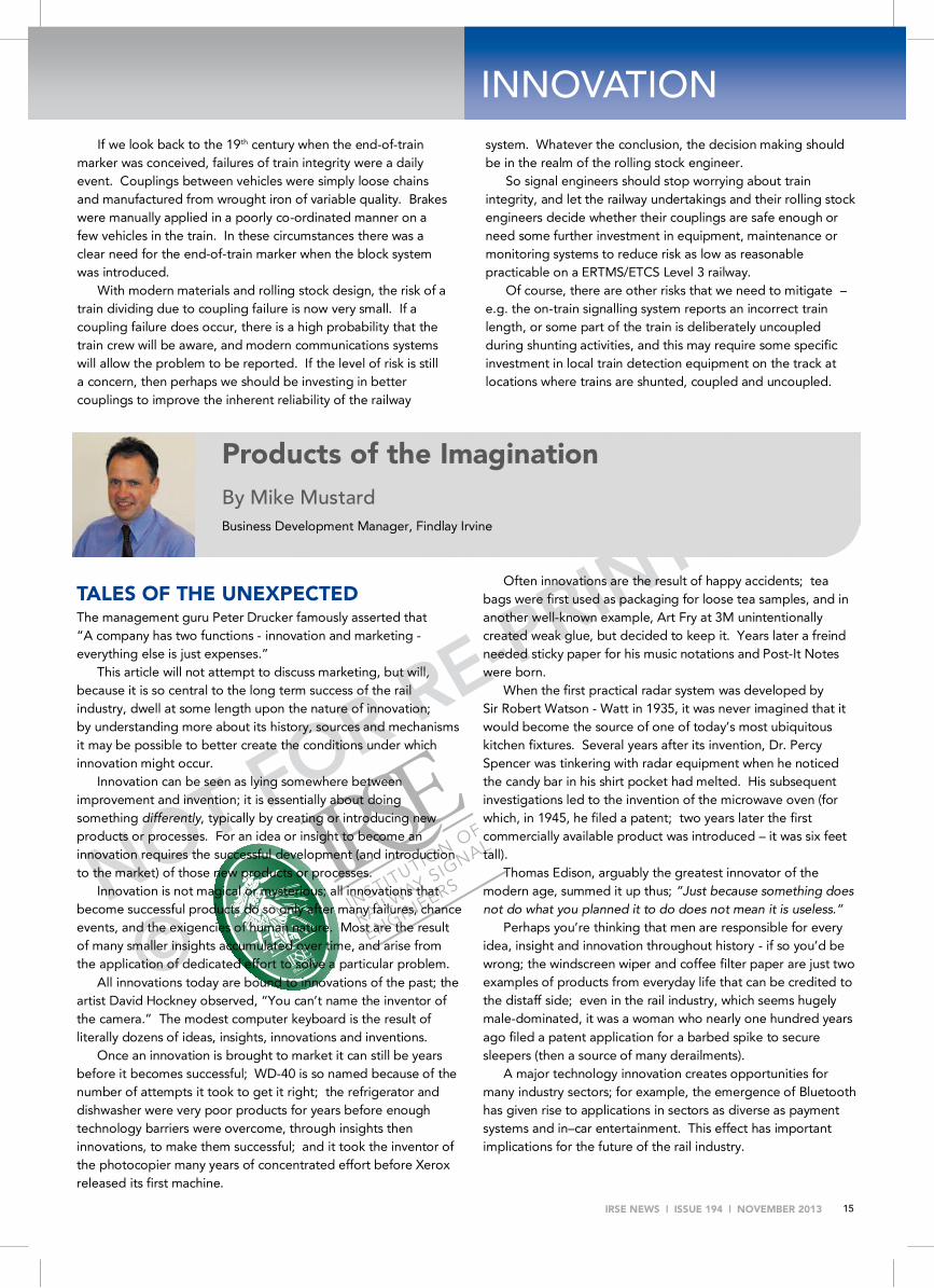
Products of the Imagination By Mike Mustard Business Development Manager, Findlay Irvine
NOT FOR RE-PRINTING
©
IRSE NEWS | ISSUE 194 | NOVEMBER 2013 16
INNOVATION
Innovation appears to lag in large, mature industries (such as rail networks), for reasons that are perhaps readily understandable; as organisations grow innovation becomes less attractive; they become increasingly unwilling to spend money on something that might threaten their hard–won position. Attitudes can become fixed on risk aversion and maintenance of the status quo.
Further, when technology innovations are introduced they automatically trigger pockets of resistance; change is always (in one quarter or another, real or perceived) painful. For some the fear is that an innovation could bring unanticipated or unintended (and therefore by definition negative) consequences.
IDLE CURIOSITY Thomas Edison made numerous contributions to science and innovation in the late 1800s and early 1900s, including the telephone transmitter, the phonograph (and records), motion picture projector and improvements to the incandescent electric light bulb; he patented over one thousand inventions.
Innovators like Edison tend to more easily make connections between unrelated ideas; he worked in many disciplines and across many sectors at the same time.
In a recent survey, modern day innovators (engineers, scientists, programmers and others) said they got their best ideas by exploring areas in which they were not expert. The ideas found during these explorations sparked new ways to think about the work in their own domain. Without the history and preconceptions of those in other fields, the innovators could find new uses for ‘old’ ideas.
This suggests organisations that regularly work across diverse sectors and disciplines may be naturally better placed to produce innovations; when they align to stay abreast of current thinking and technology developments across many disciplines, organisations increase their chances of finding and applying innovations from outside their own industries or market sectors.
Deep technical expertise in a range of technologies is a distinguishing feature of these multi-sector organisations, which will typically employ engineers better able to switch between sector-specific disciplines, leading to a natural abundance of opportunities to bring ideas and innovations from one sector to another. This happy circumstance should give them advantages compared to single-industry focused companies.
It is highly typical that the multi-sector firm has deep domain experience in each sector in which it works.
If mistakes, false starts and blind alleys are the defining characteristics of the history of innovation and invention, what lessons can we learn that could be applied to help the uptake of innovation in the rail industry? A brief tour of innovation through time will hopefully be illuminating.
BLOOD, SWEAT AND TEARS From the 1600s to the 1900s, innovations in science, medicine, astronomy, communications, transportation, agriculture, printing and mass production brought about waves of social, cultural, economic and environmental change, but it was in the Industrial
Revolution, starting in Britain in the 18th century, that the power of concentrated effort was demonstrated in full.
It is hard to summarise in a few sentences that extraordinary period of multiple innovations and inventions, but the intense focus on a set of well defined problems is surely one of its defining characteristics.
Multiple innovations occurred in the areas of textile manufacturing, mining, metallurgy and transport, and the effect was cumulative. The revolution was driven by cheap energy from coal, which enabled a huge increase in the production of cast iron and meant industry was no longer constrained by the need for water to power mills.
The steam engine, originally developed in the early 18th century, was used to transform both steamboat and railway transportation. Telegraphy also developed into a practical technology in the 19th century to help run the railways safely.
The invention of (and many refinements to) the incandescent light bulb, starting early in the 19th century, meant factories could dramatically increase output.
The so-called Second Industrial Revolution (roughly, the period from the last third of the 19th century until World War 1) can be distinguished from the first (predominantly British) on several counts; firstly, it took part largely overseas (primarily in Germany, France and the US); secondly, it was based on the development and exploitation of ‘derivative’ technologies (chemicals, electricity, petroleum); finally, it actively employed highly structured research techniques, so the approach to innovation was directed.
The lessons from studying innovation in both Industrial Revolutions are clear; an intense focus on well-defined problems will produce innovations, and the proximity of active innovators from multiple sectors creates a fertile breeding ground for new ideas.
CHANCE WOULD BE A FINE THING When Steve Jobs was asked how innovation could be managed, or made more predictable, he replied, “It can not.” Organisations might have a system for trying to manage innovation, or a strategy for managing the risks inherent in new ideas.
The goal of innovation management is to give an organisation the ability to respond to opportunities; it involves staff at all levels contributing creatively to development, manufacturing and marketing. Collaboration is an important source; innovations are increasingly brought to the market by networks of firms working together.
Innovation is best conducted in a systematic fashion so that the challenges, uncertainties and opportunities affecting the development of new products are identified at the earliest opportunity. Innovation should be managed systematically using an innovation process, the purpose of which is to try to direct systematically the development of innovative products.
Network Rail has developed its own innovation process, and it has established a Rail Innovation and Development Centre that can be used to trial new and enhanced products.

NO
T FO
R R
E-P
RIN
TIN
G©
IRSE NEWS | ISSUE 194 | NOVEMBER 2013 17
TRAIN OF THOUGHT British trains today carry more passengers than at any time for half a century, and that is forecast to grow significantly over the next thirty years - the period during which the industry wants to double capacity whilst halving costs. This ambitious goal can only be met by the judicious adoption of new technologies, and innovation has been explicitly named as a strategic enabler for this.
However, the very nature of the industry, comprising multiple bodies with overlapping interests, a high degree of regulation and an appropriately obsessive focus on safety, makes the introduction of innovations a necessarily slow process.
In 2007 the Department for Transport (DfT) introduced a White Paper, ‘Delivering a Sustainable Railway’. The first ever ‘Rail Technical Strategy’, produced to support this, called for the industry to think systematically about future technology needs and opportunities, and how those might be introduced.
An updated Rail Technical Strategy was published in December 2012, in support of which the DfT has proposed a £50m innovation fund be made available over the next five years.
In addition, Network Rail has published on its supplier portal a list of challenges and technology areas for which it is seeking solutions - a good example of using well-defined problems to direct and concentrate innovation effort.
However, as noted above, the pace of innovation in large, mature organisations like rail network operators might well be perceived to lag other industries, but perhaps it is not a lack of innovation per se that is the problem; rather it is a combination of structural factors (scale, complexity, regulation) and an historic over-dependency on ‘big’ company suppliers that by their nature are indisposed to innovation.
The smaller, nimbler, multi-sector organisation can better adopt and adapt innovations from other sectors into rail; consider this – knowledge and experience of the technology necessary to measure road surface conditions (water coverage, salt levels, temperature) makes the design of a clip-on wireless rail temperature sensor a lot easier (see diagram). Innovation is the key to the safe expansion of capacity.
CONCLUSIONS Innovation is central to the future success of the railway in Britain, especially given the lofty ambitions set out for the next thirty years. But the industry has suffered from a poor reputation for innovation, partly due to structural factors.
Finding new ways to innovate, or creating the environment in which innovations might better emerge, is a major challenge; but perhaps by its nature the small, multi-sector organisation may offer a ray of hope.
There is nothing new under the sun; two thousand years ago the Roman philosopher Seneca observed “Luck is what happens when preparation meets opportunity.” For ‘luck’ read ‘innovation’.
In Africa, Rift Valley Railways (RVR) has begun a US$9·3m roll-out of automated train warrants and GPS-based train location on its network in Kenya and Uganda, employing technology supplied to rail operators in Brazil, Argentina and South Africa.
The Translogic integrated logistics management platform will provide detailed information on train positions and loads. The aim is to enable all movements between Mombasa and Kampala to be managed from a single control centre in Nairobi, allowing better use to be made of capacity. This is expected to help cut transit times from eight to four days by 2015.
'The introduction of satellite navigation technology to this core component of our operations means we will eliminate a lot of waiting time at stations by giving priority track access to trains carrying cargo and also allow us to handle larger fleets,' said RVR Group CEO Darlan De David. Staff training is being provided by América Latina Logística of Brazil.
RVR launched a US$287m five-year investment programme for the 2 352 km network in 2011, supported by development loans of US$164m. Track renewals on 73 km of the Mombasa - Nairobi route have recently been completed at a cost of US$20m, with modernisation of a further 300 km due to follow.
RVR has undertaken to be carrying 1·9 billion tonne-km of freight between Mombasa and Kampala by June 2014.
Rift Valley Railways train control

NOT FOR RE-PRINTING
©
IRSE NEWS | ISSUE 194 | NOVEMBER 2013 18
INDUSTRY NEWS
Hong Kong's metro operator MTR has awarded Thales a contract to provide a signalling system on the HK$64.9bn ($8.36bn) Shatin to Central Link (SCL) metro line. Under the contract, Thales will add its signalling structure to the SCL's Phase 1 segment using a Communications-Based Train Control (CBTC) system. The project also involves upgrading the Ma On Shan Line (MOL) and West Rail Line (WRL) to facilitate fully automatic train operations.
Thales installed its CBTC system on MOL and WRL tracks in 2003-4. The new SCL project will link a number of existing railway lines to form two strategic railway corridors, East West and North South. The existing MOL line, which starts at Wu Kai Sha Station, will connect with the WRL line, forming a continuous 57km line that is intended to improve connectivity to the New Territories.
Hong Kong MTR signalling contract
Siemens has received an order from the transportation company Entreprise Métro d'Alger (EMA) to equip the extension of underground line 1 in Algiers with a signalling system. The new segment of the first automatic metro line in Algeria's capital city runs underground and adds four stations to the existing line.
The scope of supply includes the Trainguard MT Communi-cations Based Train Control automatic train control system, the Airlink radio transmission system, and the Digiloc train locating system. The contract also includes training of the customer's personnel in the use of the new technology. The order is worth around 20 million Euros. Commissioning of the extension is scheduled for summer 2015.
Algiers Metro signalling contract
Bombardier Transportation, as the lead member of a consortium with Trans-Signal-Rabita Ltd, the Azerbaijani railway construction and installation company, won a major new and first signalling order from Azerbaijan Railways CJSC on the 503 km long Baku-Boyuk-Kesik line.
The total value of the consortium's contract is approximately $288 million (217 million euro) with Bombardier's share valued at approximately $203 m (153 million euro). The contract covers the design, manufacture, supply, installation, testing and commissioning of the double track line. The system will provide continuous ATP , the high capacity EBI Lock 950 Computer-Based Interlocking with new R4 Central processors, EBI Track train detection and axle counters, as well as EBI Screen central traffic control systems.
Bombardier has over 14 years of experience in delivering technology for this network having equipped over 220 stations in the CIS and Baltic countries.
Commissioning is planned in four phases, with final completion in 2017.
Azerbaijan Railways signalling contract
The Los Angeles County Metropolitan Transportation Authority (Metro) has selected Atkins to serve as a General Engineering Consultant (GEC) in support of Metro’s rail network operations, maintenance and expansion plans. Metro is the third largest transit agency in the US and it operates the country’s most modern and cost-efficient rapid transit system, and carries about 50 million passengers a year.
Jon McDonald, Atkins’ business sector manager, said “Los Angeles is one of the nation’s largest, most populous counties and Metro is the country’s third-largest transit agency, having built six rail lines with almost 90 miles of track and 80 stations since opening its Blue Line in 1990. With funding from a variety of sources, the Authority is likely to spend more than $20 billion over the next 10 years to maintain, upgrade and expand its rail system. This selection positions our transit and rail group with a major new client in a new market, and we’re pleased that Metro recognises the wide range of skills we bring to the table.”
Atkins will be part of a GEC framework and companies are selected on an as-needed, task-order basis to bid to provide such services as:
• Computer-Aided Design and Drafting (CADD); • train control design, programming and review; • communication design; • traction power design and relay calibration; • civil/facilities design.
Los Angeles Metro consultancy
Network Rail has entered the next phase of its ERTMS trials. Britain’s infrastructure manager has begun testing Infrasig’s
trackside equipment, having completed initial trials with SSL technology. Network Rail is conducting the testing, which will assess equipment from four suppliers over the course of the next 18 months, along a five-mile section of down line on the Hertford Loop using a converted Class 313 laboratory train.
ERTMS and ETCS will gradually be installed in the UK over the course of Control Phase Five and Control Phase Six, starting with an overlay on the Great Western main line and the southern end of the East Coast main line. By introducing in-cab signalling, Network Rail will be able to reduce headways and as a result increase capacity on the existing network.
Network Rail’s client Simon Whitehorn said “ETCS will have a huge impact on the railway and it is vital we thoroughly test our equipment to get it right first time. Testing has gone very well and even in the first few days we were able to get the cab and trackside equipment communicating and complete the planned tests”. He added “Switching the test facility on was a big moment for the team and it’s a big step towards eventually rolling cab signalling out across the country”.
Network Rail ERTMS trials
NOT FOR RE-PRINTING
©
IRSE NEWS | ISSUE 194 | NOVEMBER 2013 19
Norway has announced on October 2013, that it is to invest NOK 7 billion ( 809 million) in upgrading its signalling system over the next 10 years with ERTMS as a key priority.
In September 2013, Jernbaneverket announced that it was to begin testing ERTMS on the Østfold Eastern line. Trial runs of the in-cab signalling system will begin in November 2013 between Rakkestad and Sarpsborg. The plan also sets operational targets which seek reduced line closures, fewer cancelled trains and increased capacity on urban commuter services.
To identify other ways in which it would be improving services across the country, Jernbaneverket has highlighted projects including the NOK 130 billion ( 16 billion) InterCity programme and the Follo Line which it aims to start in the next few years.
Norway to Upgrade Railway Signalling
It was announced in September 2013, that the new Dingo to Bluff rail line will use Siemens rail automation interlocking technology to increase the capacity of the line that will help to deliver 27 million tonnes of coal each year from the surrounding mines to the Wiggins Island Coal Export Terminal in Australia.
Aurizon are constructing the Wiggins Island Rail Project and selected Siemens WESTRACE MkII interlocking technology for the Dingo to Bluff segment of the project. The project involves duplicating 24 km of track between Dingo and Bluff to increase the capacity of coal trains on the Central Queensland Coal Network.
Siemens will design, manufacture, install, test and commission the four signalling stages for the project which will include new and modified infrastructure. The project was awarded in June 2013 and will be completed in mid 2015. Siemens Head of Rail Automation, Andrew Howey says Siemens WESTRACE MkII technology will help increase the productivity of the line.
“Based on our New Zealand experience this signalling system is extremely reliable, with data showing on average less than one failure every hundred years. However in the unlikely event of a failure the beauty of this leading-edge technology is that it can be put back in service within a couple of minutes,”
The project, which is part of the Aspect3 Alliance, is employing approximately 80 people. Siemens has a strong presence in Queensland rail infrastructure with involvement in a range of projects that are part of the Aspect3 Alliance.
Siemens is also providing more than 160 heavy haul electric locomotives for coal haulage in Queensland for a number of mining projects with three Siemens electric locomotives replacing the need for five.
Queensland railways signalling
Atkins’ rail apprenticeship scheme will see its apprentices achieve Engineering Technician (EngTech) status, having been approved by The Institution of Engineering and Technology (IET). The scheme, which is run by Atkins’ Rail Communications Systems (RCS) business, has been formally recognised by the IET for not only providing apprentices with professional competence, but for demonstrating a commitment to their development and progression.
Philip Parker, head of design for Atkins’ RCS business said “Our scheme is designed to provide apprentices with the technical skills and knowledge they need for a successful career in the rail industry so we are thrilled that it has gained IET approval. This recognition shows that the training we provide our apprentices with is of such a high calibre that they can use the qualifications they gain as full competence evidence for EngTech professional registration which provides them with more opportunities. Since gaining IET approval in July, five of our apprentices have received EngTech status. I’d like to congratulate James Winson, Andre Blackwood, Sean Doherty, Chris Bailey and Alex Sammut on this important milestone.”
Meanwhile, Atkins has welcomed one of the largest intakes of young people in its 75 year history, with more than 400 graduates and apprentices joining its UK business. The 330 graduates and 75 apprentices will fulfil a wide variety of roles, from engineers, environmentalists and management consultants to scientists and planners. Based in offices across the UK, they will work within Atkins’ Energy, Rail, Water & Environment, Highways & Transportation, Design & Engineering and Defence, Aerospace & Communications business units.
Apprenticeship scheme fast-tracks careers

NOT FOR RE-PRINTING
©
IRSE NEWS | ISSUE 194 | NOVEMBER 2013 20
IRSE MATTERS
The fourth Minor Railways Section Signalling Maintenance and Inspection Workshop was held at Signet Solutions Ltd in Derby over the weekend of the 28 and 29 September 2013. There were fourteen delegates that attended the workshop representing nine minor railways from around the UK.
The workshop is designed to give delegates from the S&T Departments of Minor Railways, an introduction into Minor Railway S&T inspection and maintenance principles, procedures and practice, included theory and practical sessions.
Saturday covered the requirements of the law and regulations, record keeping, ownership and responsibility, an overview of mechanical and power operated points, gauging, maintenance and cleaning. This was followed by an introduction to mechanical signals, the operation, testing, maintenance and cleaning including both the theory and practical phases.
The delegates and course staff enjoyed a course meal on Saturday evening in convivial surroundings in a local Derby restaurant where the exploits of the day could be recalled by all.
Sunday consisted of a d.c. track circuit’s overview, drop shunt testing maintenance and adjustment. A short session on risk reduction by Green Dragon Rail was followed by discussions regarding site diagrams and records, wire degradation, silver migration reporting, recording and ensuring safety.
A big thank you goes to our sponsors, Park Signalling, Signet Solutions Ltd and Green Dragon Rail, without whom running this workshop would not be possible.
MINOR RAILWAYS SECTION Report and photos by Major Ian Hughes
Signalling Maintenance and Inspection Workshop
Fourth Minor Railways Section Signalling Workshop
1 Workshop attendees pose with Andy Knight (far left) at Signet Solutions.
2 Andy Knight (middle) in full swing during one of the practical sessions of the workshop.
The workshop is proving to be very popular and is consistently oversubscribed. Feedback from this year’s students was extremely positive and as this workshop was oversubscribed, it is proposed to be run once again in September 2014, subject to obtaining Industry sponsorship. The dates will be provided closer to the time within IRSE NEWS and on the Institution website. So if you wish to attend or sponsor next year’s workshop, please contact the workshop coordinator via [email protected].
1
2

NOT FOR RE-PRINTING
©
IRSE NEWS | ISSUE 194 | NOVEMBER 2013 21
I would like to add some updates to Anthony Howker's article in the July/August 2013 issue of IRSE NEWS.
I particularly want to add to the Queensland information by saying that there were a number of influences on the types of signalling installed over its almost 150 years of main line operations, these being UK practice, engineers and contractors, and the Railway Commissioner who signed off on just about everything until later times. Two significant influences were the Brisbane electrification proposals of the 1950s and 1970s and heavy haulage of coal (Moura line, 1970) which saw the introduction of remote controlled interlocking and the spread of power signalling (1962). Other influences on train operations was economy of operations which saw the widespread use of self-resetting points and unattended crossing stations which were later complimented by Train Order and Direct Traffic Control (DTC) systems. In recent times, capacity optimisation has been a driver in the consideration of ETCS.
Not often realised are the many 610 mm gauge sugar cane railway systems of Queensland. According to the Bureau of Infrastructure, Transport and Regional Economics (2012), there is a combined route length of 'around 4000 km', which makes it larger in size than the '3281 km' broad gauge networks of the southern states! I would not have thought that there was 4000 km of sugar cane railways, perhaps around 1000 km (?), but needless to say this is a large network with their own systems of signal indicators, GPS and radio dispatching of trains.
The first power interlocking in Australia was as mentioned in the article, Brisbane Central, although it was 1904 rather than 1905 that it was introduced. The power frame installed by McKenzie & Holland was a Westinghouse style B of 23 levers and until 1917 when the frame was extended to 36 levers, it was likely that treadles instead of track circuits were used in train detection.
Along with other states, three-position upper quadrant signalling came to Queensland in 1919 with a short section between Toowong and Sherwood on the Ipswich line. Until the 1924 extension to Roma Street, the system used pointed yellow and black arms (similar to that which is shown on the cover of IRSE NEWS Issue 191) with a staggered white marker lamps on automatic signals and red and white square end arms with a vertical white marker lamp on controlled signals. From then on, all arms were of square ends and red and white in colour. The marker lamps were also removed.
Influenced by McKenzie & Holland's presence at the Sydney International Exhibition of 1879, like New South Wales, the Queensland Government introduced interlocking (1882) and went on to entice McKenzie & Holland to set up their Brisbane Northgate factory (The Toombul Iron Interlocking Works) in preparation of the 1890 introduction of Tyers block telegraph and interlocking of stations between Oxley - Brisbane Central - Northgate (then referred to as Toombul).
The only line outside of the Brisbane suburban area to have used double line automatic signalling was the few kilometres between Stuart (near Townsville) and Nome. While it could be argued that the double line sections between Ipswich and
Helidon on the western line originally were automatic when colour light signalling was introduced, it was part of a supervising CTC system and became controlled signals when a local signal cabin was cut-in. Today, there are many kilometres of double lines controlled under the Remote Controlled Signalling (CTC) system.
While the use of a train stop was considered for the 1950s Brisbane electrification, this electrification scheme was never completed. Following a number of fatigue related incidents brought on by the introduction of diesel hauled trains, a 'Station Protection' system was introduced in the early 1960s. Similar to AWS functionality and equipment, fixed magnets were installed on the approach to crossing stations, triggering the alerting system on a locomotive and applying the train brakes should the train crew not respond within a set number of seconds. The ATP system referred to between Caboolture and Rockhampton appears to be the now decommissioned Ericsson intermittent ATC system introduced in 1988. The continuous (with radio infill) referred to is the Westinghouse ATP system trialled from 1991 and introduced from 1993; now covering the Ipswich - Toowoomba, Caboolture - Purono (Townsville), and Townsville - Mt Isa lines. The latter section uses this ATP system in conjunction with its DTC system.
Phillip Barker, Brisbane [email protected]
FEEDBACK
Re: Train Control over the Past 100 Years of the IRSE: A Brief History in Australia and the Rest of the World. Part 1.
IRSE NEWS 193 Cover Picture I note with interest the cover picture on the previous IRSE NEWS showing signals mounted on OHLE structures.
Network Rail recently commissioned a three aspect banner mounted in a similar manner and I wondered if your readers would be interested in seeing a photo of that as a sort of compare and contrast?
Mick Turner Senior Design Authority Engineer - Signalling
Signalling Innovations Group, Network Rail

NOT FOR RE-PRINTING
©
IRSE NEWS | ISSUE 194 | NOVEMBER 2013 22
Signalboxes By Michael A.Vanns
ISBN 978 0 7110 3537 9 Second Edition 2013
Published by Ian Allan Publishing Ltd, Riverdene Business Park, Hersham, Surrey, UK
This detailed and picture filled book, which has been published this year in a softback format, updates the situation in the UK from the first edition of 1997. With the onset of the planned fourteen UK Network Rail Regional Operations Controls that were announced back in 2010, the days of the mechanical signal box and Power Signal Box are now limited. There are currently just over 700 mechanical signalboxes, panel signalboxes and Signalling Centres controlling the UK national network. Since the first edition of this book, almost 350 signalboxes have closed.
With an interesting introduction with acknowledgements, the book begins by looking at the interest of individuals and groups since the 1950’s regarding the recording, classification and listing of such an important industrial archaeological asset as the humble signalbox and the books that have been written to record the differing styles and types.
The evolution of the signalbox is reviewed in detail looking at key stages of their development between 1850 to 1870, 1870 to the 1880’s and 1890 to 1922. This is followed by a detailed listing with illustrations of the different signalling contractor and railway company signalbox designs from 1870 to 1922.
The signalboxes of the “Big Four” railway companies between 1923 and 1948 are then considered, before the review of British Railways signalboxes of 1948 until 1981. These subjects are both provided with a detailed listing with illustrations of the different railway company and regional signalbox designs.
BOOK REVIEWS
Modern signalboxes and signalling centres after 1981 conclude this section of the book, looking at replacement and new signalbox structures for the modern railway with the need for “a psychological visual link to the outside”.
The next section of the book looks at the anatomy of the traditional mechanical signalbox itself and the key parts within it, along with valid reference to the working environment and the people who acted as signalmen and signalwomen, who helped make the railway run 24/7.
Moving on into the 21st Century with planned signalbox closures and then onto Preservation, it is warming to know that many signalbox structures have been preserved and listed either in situ on the UK national network or relocated and preserved at the many minor railways around the UK. A detailed listing is again provided of these listed signalboxes.
The book concluded with another detailed listing of the surviving signalboxes on the UK national network between 1997 and 2012. An interesting and useful item of reference material, the book is totally enhanced with the provision of so many colourful pictures of the many signalboxes it refers to, but future issues should also focus on the developing Regional Operations Controls of the future and the new signalling technology they will contain.
The Editor
Leicester PSB since closure

NOT FOR RE-PRINTING
©
IRSE NEWS | ISSUE 194 | NOVEMBER 2013 23
Other books reviewed recently With Christmas coming up, we thought it might be useful to remind you of some other books that have appeared in the NEWS
Issue 189: TRAIN WRECK
The Forensics of Rail Disasters
By George Bibel
For those of you that have read the British classic "Red for Danger", this book from George Bibel, a professor from the University of North Dakota is a fascinating insight into the world of rail investigators from a US perspective in the main.
Bibel takes us on a journey from the fundamentals as to why trains crash, the trends through the history of railroads, through to scenarios resulting in crashes and cites many specific such cases.
Issue 191: Principles of Railway
Operation By John Glover
This detailed and colourful book, which is published for the first time this year in a hardback A5 format, clearly outlines the complex UK railway industry and how it all fits together to operate on a daily basis. For an individual who is just starting out within the industry or for somebody who has worked in the industry for a long period, this book will surely become a bible in order to understand the whys and wherefores of the industry as a whole.
Issue 188: Railway Signalling in
Scotland
A Brief History and Overview
By Simon Lowe MIRSE Beginning with Scotland’s first recorded signal box at Cowlairs in 1842, the development and technology advancement/innovation is clearly demonstrated in the text and pictures between the evolving railway companies. This includes reference to radio communications in support of signalling systems.
100 Years of Railway Signalling and Communications
This textbook records the contribution of the IRSE to the development of the safe and efficient systems that are used to control railways throughout the world today.
It is written in a narrative style,
to be read as a whole or in parts, and all members and others interested in the profession will find something of interest in it.
Available to members at a special price of £33,
on-line at www.irse.org or through the London office.
Issue 185: TRACKatlas of Mainland
Britain
2nd Edition This book presents a complete track plan of the British national rail network, laid out geographically and to scale as far as possible (as opposed to the ‘Quail Track Diagrams’ which are entirely diagrammatic).
Issue 192: Signalisation et
automatismes ferroviaires / Railway signalling and
automation The bible of European railway signalling
and automation as a bilingual (English/French) book in three volumes.

NOT FOR RE-PRINTING
©
IRSE NEWS | ISSUE 194 | NOVEMBER 2013 24
Do you realise? .......that if you can not claim the full member-ship subscription from your employer, you may be able to claim it as an allowable expense against your income tax.
For instance, in the UK the IRSE is recognised as an approved professional body by HMRC, and they will take the cost of the subscription into account when calculating the tax you pay.
Members in other parts of the world should seek
advice from their local IRSE Section or contact the relevant tax authority.
In the UK this tax relief only applies whilst you are
working, not once you retire.
Christine White Membership & Professional Development
Manager
IRSE Merit Awards
IRSE Merit Awards, introduced in 2006, are awarded by the Council to a volunteer or staff member anywhere in the world to recognise meritorious service to the Institution.
Nominations can be made by any member. Meritorious service is defined as making a substantial contribution to the Institution’s work over a period of time by organising activities, or carrying out specific tasks which have furthered the Institution’s aims and objectives. The award consists of a suitably engraved plaque.
If you think of someone who should be considered
for such an award, please contact the Chief Executive at [email protected] with details of why they should be considered.
Colin Porter Chief Executive
MERIT AWARDS
MEMBERSHIP
When should I take my IRSE Exams? Passing the IRSE Exam is a significant step towards recognition as a professional engineer within our industry, often in conjunction with gaining IEng or CEng applicable to the wider engineering profession. As such, the exam is aimed at individuals who have sufficient understanding of the industry to confidently answer questions on several topics within the syllabus for each module. Unfortunately, every year there are candidates who fall significantly short of this level, which has caused the Exam Committee to discuss whether to propose any entry level requirement. Ideas have included a minimum period of experience within the industry, or for all exam applications to be countersigned by someone who had previously passed the exam. On balance we have decided against any absolute requirement because no option would filter fairly without introducing barriers for valid candidates, especially those from unusual careers, backgrounds or locations.
Rather than attempting to filter applicants, we encourage you to consider whether you are ready. Often, you could competently tackle your first module(s) based on your current job once you genuinely understand WHY you are doing things (rather than merely applying rules), whereas to achieve all four modules you may need wider and more responsible industry experience.
Having decided you have sufficient knowledge, attempt some past papers under exam conditions and have them reviewed by a colleague. For some candidates sitting for 90 minutes with a question paper can be unfamiliar and tiring; a mock exam will help to refine one's time management. The review of your answers could be done by a mentor, study group leader, senior colleague or a fellow candidate; they should consider whether it answers the question asked, is well structured and is well matched to the mark allocations. If you do not have such support, you can review the answers yourself – but do this at least a week after having attempted the paper.
We wish all candidates well, whether applying for 2013 or preparing for fture years.
The IRSE Exam Committee
This advice, and more besides, appeared on page 25 of Issue 190 of the NEWS
IRSE EXAMS
EurIng Registration The professional title, EurIng belongs to FEANI, an organisation with over 3.5 million professional engineers from 32 European countries, whose aims include the mutual recognition of qualifications in Europe.
IRSE members who are CEng registrants are eligible to apply for EurIng registration and this can be done through the IRSE. If you would like more details please contact Christine White, Membership and PD Manager.
REMINDERS

NOT FOR RE-PRINTING
©
IRSE NEWS | ISSUE 194 | NOVEMBER 2013 25
IRSE Scotland Annual Dinner It is the time of year again when the Scottish Section have the pleasure of inviting members to take a place at the IRSE Scottish Section Annual Dinner on Thursday 14 November 2013. This is now firmly established as the largest annual rail event in Scotland, whilst retaining an informal and friendly atmosphere. The dinner will be served at 20:00 with guests assembling in the bar area from about 19:30 following the lecture in the adjacent room.
Continuing from previous years’ successful events, we are holding the dinner in the Marriott Hotel, Argyle Street, Glasgow, following the November IRSE lecture (“Subway Modernisation - The Past, The Present and The Future”). We are grateful to Siemens Rail Automation for their financial support for this year’s event, without which we would struggle to hold the ticket prices at the realistic levels previously enjoyed by members and their guests.
Ticket prices for IRSE members (all grades including retired members) and licence holders have been fixed at £23 per person with a special rate of £18 for Younger Members. Owing to the near sell-out numbers attending last year, you are urged to respond sooner than the closing date of 31 October to avoid disappointment.
If you would like to attend the Annual Dinner, please contact Peter Allan, Events Co-ordinator. Companies wishing to take a table at the event should also contact Peter for a separate Corporate Booking Form. Should you
require any further information, please call Peter on 0141 242 8666 or email [email protected].
RECRUITMENT To advertise call Andrew: +44(0)208 652 5214 e-mail: [email protected]
ANNOUNCEMENTS
194 and counting ……
As you may have noticed, this magazine is coming up to Issue 200.
In order to prepare for this forthcoming issue, some planning is taking place!
We are looking for pictures related to the speed of 200 km/h and to be able to borrow or be loaned ERTMS lineside marker boards for a potential photo shoot.
If you or your company can assist with either or both of these requests, we would very much appreciate if you can make contact with us at [email protected] before the end of November 2013.
IRSE NEWS @ 200
We are BOMBARDIER Get on board; we can drive you further in your career!
Bombardier Transportation is the number one provider of rail
solutions in the world. Our business holds the number one global market position in eight of the ten markets we service. For our Rail Control Solutions division in Plymouth we are looking for:
ERTMS Senior Signalling Integration Engineer and
ETCS Onboard Project Engineer
With over 50 years experience in providing the latest signalling technology, the Rail Control Solutions Plymouth site focuses on
product design, application engineering, business development, and project management activities. Your profile: If you have experience in UK Wayside or Onboard Application Engineering and a strong knowledge of the UK Railway Signalling rules and regulations, we want you in our team! How to apply: For more information on the roles and how to apply, please use this link:
http://jobs.bombardier.com/job/Plymouth-Senior-Signalling-Integration Engineer-ENG/15459900/
If you are a person who thrives on challenges, on development and is eager to work on exciting projects, we are expecting you to apply!
.

NOT FOR RE-PRINTING
©
IRSE NEWS | ISSUE 194 | NOVEMBER 2013 26
ADMISSIONS We have great pleasure in welcoming the following members newly elected to the Institution:
Companion Copeland P Siemens Rail Automation UK Higham S Atkins - Rail Engineering UK
Member du Plessis D J R & H Rail South Africa Egloff A Siemens Schweiz Switzerland Gibson A C Midland Railway Trust UK Mew J Thales Ground Transport. UK Nevasa I PT Kereta API Indonesia Indonesia Shanks C Hatch Mott MacDonald Canada van Wyk T R & H Rail (Pty) South Africa Van der Weide R Arcadis Vectra/EC Harris(UK) Netherlands
Associate Member Mondal I Ansaldo‑STS Trans Sys. India Sharma C R RailTel Corporation India
Accredited Technician Burgess D Serco UK Iqbal M S DLR UK
Associate Chai M W Land Transport Authority Singapore Everson R Network Rail UK Forbes E J L Balfour Beatty Rail UK Immers F Movares Netherlands Johnson T Atkins UK Kelly C Signalling Solutions UK Li S JMD Railtech Pty Australia Liburd F Railworks Australia Moir P W A Telent UK Ponsonby L J Parsons Brinckerhoff UK Rane T JMD Railtech Pty Australia Shack B M JMD Railtech Pty Austria Zhu Y JMD Railtech Pty Australia
Student Abbott C JMD Railtech Pty Australia Abbott G JMD Railtech Pty Australia Clayton D DEG Signal UK Collett J R A DEG Signal UK Corker T Balfour Beatty Rail Tech. UK Davey J G Rio Tinto Iron Ore Australia McCarthy A JMD Railtech Pty Australia Rai J Atkins UK Regan A Signalling Solutions UK Young W Signalling Solutions UK
TRANSFERS
Member to Fellow Buckley P A London Underground UK
Associate Member to Member Manock J L Network Rail UK Merrills R M SigAssure UK UK Mickleburgh D L MTR Corporation Hong Kong Paley G A Gap Rail UK Palmer W J C DEG Signal UK Parashar V SERCO Middle East UAE Sijabat L A M PT Len Railway Systems Indonesia Toh K T Land Transport Authority Singapore Wood S Network Rail UK
Student to Member Broderick M WA PTA Australia Phillips J R Siemens Rail Automation UK
Associate to Associate Member Calambro G Network Rail UK
Student to Associate Member Singh S Atkins (India) Pvt India
RESIGNATIONS Atkinson A G Caraviello A Churchill G Cooper W R Meijerink H Simpson C Somolu D
RE-INSTATEMENTS Elavarasan M Grant D S L Vattamattathil S
DEATHS It is with great regret that we have to report the death of the following member:
Sutton E F Member
Current Membership: 4792
MEMBERSHIP MATTERS