irrigation and drainage design and construction
TRANSCRIPT
Ethiopian TVET-System
Irrigation and Drainage Design and
Construction
Level-III
Based on March 2017 GC. Occupational Standard
Module Title: Maintaining and Repairing Irrigation
Canal and Structures
TTLM Code: EIS IDC 3 TTLM 0920v2
Irrigation and Drainage Design and Construction
Level III
Author/Copyright: Federal TVET Agency Version -1
September 2020
Page 1 of 135
This module includes the following Learning Guides
LG56: Plan and prepare for work
LG Code: EIS IDC3 M15 LO1-LG-56
LG57: Maintain irrigation channels and drainage assets
LG Code: EIS IDC3 M15 LO2-LG-57
LG58: Check work and restore work site
LG Code: EIS IDC3 M15 LO3-LG-58
LG59: Finalize work
LG Code: EIS IDC3 M15 LO4-LG-59
Irrigation and Drainage Design and Construction
Level III
Author/Copyright: Federal TVET Agency Version -1
September 2020
Page 2 of 135
This learning guide is developed to provide you the necessary information regarding the following
content coverage and topics:
1. Determine Work requirements from plans, drawings, specifications
2. Site checking and hazard identification
3. Appropriate arrangement of drainage and inflow diversion
4. safety requirement of Equipment and excavation method
5. Personal protective equipment
This guide will also assist you to attain the learning outcome stated in the previous page. Specifically,
upon completion of this Learning Guide, you will be able to –
Identify work requirements from plans, drawings, and specifications.
Identifying potential hazards
Arrange temporary diversion work from work site.
Identify tools, equipments and excavation method
Use Personal protective equipment
Learning Instructions:
1. Read the specific objectives of this Learning Guide.
2. Follow the instructions described below 3 to 4.
3. Read the information written in the information ―Sheet 1, Sheet 2, Sheet 3 and Sheet 4‖inpage
3, 13, 20,24 and 37 respectively.
4. Accomplish the ―Self-check 1, Self-check 2, Self-check 3 and Self- check 4‖ -‖ in page 11, 18,
23, 34 and 43 respectively
5. If you accomplish the self-checks, do operation sheet in page 45
6. LAP Test in page 46
Instruction Sheet Learning Guide-56: Plan and prepare for work
Irrigation and Drainage Design and Construction
Level III
Author/Copyright: Federal TVET Agency Version -1
September 2020
Page 3 of 135
1.1 Introduction
An essential aspect of the project, collecting requirements process helps to define
project scope during scope management. With some set of tools and techniques to
gather requirements for projects, it's the responsibility of a project manager to ensure
capturing all the requirements. As a project manager, it‘s essential to be very agile while
collecting requirements and also it is necessary to use appropriate requirement
gathering tools during the project lifecycle. Ensuring not to miss any requirements of the
project outcome, a project manager is liable for the success of the project.Requirements
are not the same as project objectives. The objectives should drive the requirements.
Objectives are what you want to accomplish, requirements are how you will accomplish
those objectives.
1.2 Extent of work
In repair and maintenance of irrigation assets, the term ‗scope of work‘ or extent of work
is a very general term referring to a general description of the work that is expected to
be performed under a particular contract. It may be prepared by the client or their
consultants and included in tender documentation for construction works. A scope of
work can be a useful way of agreeing broad project requirements for both the client and
supplier.
Without a defined scope of work, there‘s no way to know what work must be done. That
means it‘s incredibly important to establish the scope when contracting to show what
tasks must be done, who‘s responsible for those tasks, and the project schedule, and
any other necessary details for contractors and subs. Without a clearly defined scope of
work, the potential for defects, payment disputes, and project delays will soar.It
establishes a baseline of rights and obligations. A scope of work isn‘t set in stone,
though – they‘re commonly modified via change orders and partial terminations.
Information sheet – 1 Determining Work requirements
Irrigation and Drainage Design and Construction
Level III
Author/Copyright: Federal TVET Agency Version -1
September 2020
Page 4 of 135
There‘s no single way to set out the scope of work. Still, there are some general
considerations that should be included.
Project Overview: A short, concise statement summarizing the project
description.
Project Deliverables. This section should detail all the expected project goals
that need to be reached throughout the lifespan of the project
Project Scope: The project scope will give you essential details regarding the
precise tasks and their technical aspects.
Schedule Summary: Not a full detailed construction schedule, but rather a
general list of tasks, and related tasks for the project and when they are expected
to be completed.
Project Management: This section of the scope of work will define the
administrative procedures on the project. How are change orders handled?
When and how are payments going to be issued?
Bottom Line: Proper communication and transparency will prevent construction
payment disputes, and that starts with a crystal-clear scope of work. When both
parties understand what‘s expected, everything else tends to fall into place. Plus,
referring back to the scope of work keeps parties on task, which helps to
complete the build on time and on budget.
1.3 Site boundary
Site boundary means that line beyond which the land or property is not owned, or
otherwise controlled by the regulated entity for repair and maintenance work. The law
says you must conduct your work without putting members of the public at risk. This
includes the public and other workers who may be affected by your work.The project
client should provide information about:
boundaries
adjacent land usage
access; and
measures to exclude unauthorized persons
This will influence the measures contractors take.
Irrigation and Drainage Design and Construction
Level III
Author/Copyright: Federal TVET Agency Version -1
September 2020
Page 5 of 135
Key issues are:
Managing site access
Hazards causing risk to the public
Vulnerable groups
All construction sites require:
Measures to manage access across defined boundaries; and
Steps to exclude unauthorized people.
Site boundaries: You need to define boundaries physically, where necessary, by
suitable fencing. The type of fencing should reflect the nature of the site and its
surroundings.
Determining the boundary is an important aspect of managing public risk. You need to:
Plan what form the perimeter will take;
Provide the fencing; and
Maintain the fencing.
Questions you need to ask yourself include:
What is the nature and type of the construction work?
How heavily populated is the area is?
Who will need to visit the site during the work?
Will the site attract children?
What are the site characteristics (eg existing site boundaries, location, proximity
to other buildings)?
Typically, in populated areas, this will mean a two-metre high small mesh fence or
hoarding around the site.
Irrigation and Drainage Design and Construction
Level III
Author/Copyright: Federal TVET Agency Version -1
September 2020
Page 6 of 135
Authorization: The principal contractor must take reasonable steps to prevent
unauthorized people accessing the site.
People may be authorized to access the whole site or be restricted to certain
areas;
You must explain relevant site rules to authorized people and undertake any
necessary site induction;
You may need to supervise or accompany some authorized visitors while they
are on site or visiting specific areas.
1.4 Locating Utility
Utility location is the process of identifying and labeling public utility mains that are
underground. These mains may include lines for telecommunication, electricity
distribution, natural gas, cable television, fiber optics, traffic lights, street lights, storm
drains, water mains, and wastewater pipesBecause of the many different types of
materials different detection and location methods must be used. Preventing damage to
underground utility infrastructure is a priority for utility operators and contractors who
excavate, drill and bore in areas where there are existing utilities.
Locates are ground markings identifying the position of utility lines based on records or
electronic locating equipment, and the associated necessary documentation such as a
locate sheet.
Ground markings consist of different colors that are used to reflect each type of
infrastructure (gas, hydro, cable, etc.).
Employers are required to:
Determine the approximate location(s) of utility installations — including sewer,
telephone, fuel, electric, and water lines.
Contact and notify the utility companies or owners involved to inform them of the
proposed work.
Irrigation and Drainage Design and Construction
Level III
Author/Copyright: Federal TVET Agency Version -1
September 2020
Page 7 of 135
Ask the utility companies or owners to establish the location of underground
installations prior to the start of excavation work; which includes using detection
equipment or other acceptable means to locate utility installations.
Determine the exact location of underground installations by safe and acceptable
means.
Ensure that while the excavation is open, underground installations are
protected, supported, or removed as necessary in order to safeguard workers.
1.5 safe work method
A Safe work method statement (SWMS) is a document that sets out the high-risk work
activities to be carried out at a workplace, the hazards arising from these activities and
the measures to be put in place to control the risks. One SWMS can be used for work
that involves a work activity that requires using powered mobile plant, working at
heights of more than 2 meters and working adjacent to a road used by traffic other than
pedestrians. A SWMS is classed as an administrative control and is used to support
higher order controls to eliminate or minimize risks to health and safety. A SWMS is
generally different from other documents that focus on specific tasks or processes, such
as a Job Safety Analysis or a Safe Operating Procedure.
The principal contractor, builder and subcontractors should consult with each other to
determine who is in the best position to prepare the SWMS. Managers, contractors,
leading hands and workers should all be involved in developing a SWMS. Consulting
workers and Health and Safety Representative at the workplace they should also be
consulted when developing a SWMS. A SWMS must:
identify the work that is high risk construction work
specify hazards relating to the high-risk construction work and the risks to
health and safety
describe the measures to be implemented to control the risks, and
describe how the control measures are to be implemented, monitored and
reviewed
Irrigation and Drainage Design and Construction
Level III
Author/Copyright: Federal TVET Agency Version -1
September 2020
Page 8 of 135
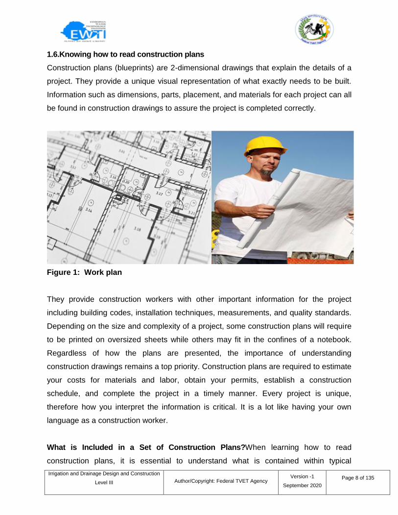
1.6.Knowing how to read construction plans
Construction plans (blueprints) are 2-dimensional drawings that explain the details of a
project. They provide a unique visual representation of what exactly needs to be built.
Information such as dimensions, parts, placement, and materials for each project can all
be found in construction drawings to assure the project is completed correctly.
Figure 1: Work plan
They provide construction workers with other important information for the project
including building codes, installation techniques, measurements, and quality standards.
Depending on the size and complexity of a project, some construction plans will require
to be printed on oversized sheets while others may fit in the confines of a notebook.
Regardless of how the plans are presented, the importance of understanding
construction drawings remains a top priority. Construction plans are required to estimate
your costs for materials and labor, obtain your permits, establish a construction
schedule, and complete the project in a timely manner. Every project is unique,
therefore how you interpret the information is critical. It is a lot like having your own
language as a construction worker.
What is Included in a Set of Construction Plans?When learning how to read
construction plans, it is essential to understand what is contained within typical
Irrigation and Drainage Design and Construction
Level III
Author/Copyright: Federal TVET Agency Version -1
September 2020
Page 9 of 135
construction plans. Most include a cover page, time block, key notes, general notes,
revision block, drawing scale and a legend. It is crucial that you read everything and
understand it before you estimate or start the construction project!
Cover Page: This page usually contains a drawing of the actual project. It also includes
the title block, revision block, notes, drawing scale and the legend.
Title Block: Each plan contains a ―title block.‖ The title block often appears at the
beginning of a set of construction plans. The shape, size, and placement of the title
block can vary. You will see things like copyright information, revision date, plan
number, creation date, scale of the drawing, and sheet number.
The title block‘s first section lists the blueprint‘s name, number, and address as well as
the location, site, or vendor. If the drawing is part of a set, that information will also be
included. If there is a blank in the title block, the drawing is not ready for release. The
authority (checker or engineer) will not sign it if there is missing information. The second
section of the title block contains routine information. Approval dates and signatures are
located here. Should you need more information regarding a project‘s construction
plans, this information should include contact information for further discussion. The
final section of the title block is the list of references.
This section lists all other drawings that are related to the building, system, component,
as well as all construction plans (blueprints) that were used as a reference or to inspire
the project.
Revision Block: Any time there is change to a building, system, or component,
the drawing must be redrafted. Those changes are listed in the Revision Block –
usually with a date as well.
Drawing Scale: Construction plans (blueprints) are scaled down representations
of the final project at a ratio of the actual size. For example, 1/8″ = 1′ (one eighth
inch equals one foot). When construction plans are scaled, it helps to put the part
into a print size drawing that is easily read by the crew.
Irrigation and Drainage Design and Construction
Level III
Author/Copyright: Federal TVET Agency Version -1
September 2020
Page 10 of 135
Key Notes: The notes will reveal any specifications, details, or information the
designer (engineer) thinks may help you understand the drawing. Some notes
may even include information as to when the project start time is, for example,
―Do not begin work until 7 am.‖ Information like this can be beneficial to the crew
and might even be a requirement of the municipality in which the work is taking
place.
General Notes: General notes eliminate the use of lengthy written explanations.
It is a note that provides technical information that will apply to the entire drawing.
Legend: Thelegendis used to define thesymbols used in the construction plans
(blueprint).
Your company might also have their own symbols for certain items. The important thing
is that you understand the meaning of the symbols regarding the plans you are
reviewing. Be sure you understand what those symbols represent by reviewing the
legend for the drawing that you‘re working with. In conclusion, if you are in the
construction industry.
Irrigation and Drainage Design and Construction
Level III
Author/Copyright: Federal TVET Agency Version -1
September 2020
Page 11 of 135
I. Choose the best answer form the given alternatives (2 pts each)
1. ___very general term referring to a general description of the work that is expected
to be performed under a particular contract.
A. Scope of work
B. Objective
C. Requirement of work
D. All
2. ______ means that line beyond which the land or property is not owned.
A. Site boundary
B. Scope of work
C. Land usage
3. AccessUtility location is the process of identifying and labeling public utility mains
that are underground.
A. Labeling
B. Utility location
C. Positioning
Grounding
4. Which one of the following is not included in the construction plan?
A. Cover page
B. Drawing
C. Title block
D. All
5. ____ is a document that sets out the high-risk work activities.
A. Safe work method statement C. Health and safety
B. PPE D. All
II. Short Answer Questions
Directions: Answer all the questions listed below. Use the Answer sheet provided in
the next page:
1. Explain the benefit of understanding extent of work. (2 pts)
Self-check 1 Written Test
Irrigation and Drainage Design and Construction
Level III
Author/Copyright: Federal TVET Agency Version -1
September 2020
Page 12 of 135
2. Briefly describe about utility locating. (3 pts)
3. What is the purpose of temporary water diversion? (3 pts)
4. Why you need to delineate work site boundary? (2 pts)
Satisfactory rating - 10 points: Unsatisfactory - below 10 points
You can ask your teacher for the copy of the correct answers.
Answer Sheet
Score = ___________
Rating: ___________
Name: _________________________ Date: _______________
I. Choose answer
1.____ 2. ____, 3. _____ 4. _____ 5. _____
II. Short Answer Questions
1.____________________________________________________________________
2.____________________________________________________________________
3.____________________________________________________________________
4.____________________________________________________________________
Irrigation and Drainage Design and Construction
Level III
Author/Copyright: Federal TVET Agency Version -1
September 2020
Page 13 of 135
2.1 Introduction
Often times, you may feel uncertain about the safety of your workplace. It is important to
be able to identify any possible safety and health hazards that may be looming around
you. If you work on a construction site, you should be even more diligent about safety.
Read on to learn how to point out hazards that may exist on your construction site.
2.2 Workplace Hazard
A workplace hazard is any potential interference with the quality of life of your
occupation that causes health and safety risks to you or others. The type of hazards
varies across industries, and there are hazards you should be aware of on your own job
or work site. The most common hazards in the workplace:
Safety hazards: They include dangerous conditions that can cause injury, illness,
or death. These hazards include:
Working from unsafe heights, such as ladders, roofs, or any raised work
area.
Unguarded machinery that can harma foot, arm, leg or any other body part
Electrical hazards such as exposed wiring, missing ground pins, and frayed
cords.
Confined spaces that can put you in danger to toxic gases, and oxygen
deficient environments. These include working in trenches, and dangers
such as entering tanks.
Biological hazards: these are related to working inside schools, colleges and
universities, hospitals, laboratories, nursing homes, outdoor occupations, and
with animals, people, or infectious plant materials that can potentially expose you
to biological hazards, which include the following:
blood and other body fluids
fungi and mold
plants
Information sheet - 2 Site checking and hazard identification
Irrigation and Drainage Design and Construction
Level III
Author/Copyright: Federal TVET Agency Version -1
September 2020
Page 14 of 135
insect bites
animal and bird droppings
bacteria and viruses
Ergonomic hazards: these hazards are the most difficult to notice because
strain put on the body can often times go unnoticed for days on end before
experiencing any pain. Short term expose can result in ―sore muscles‖ after being
exposed, but long-term exposure can result in serious illnesses on a long-term
scale. Such hazards include:
Awkwardly and improperly adjusted workstations and chairs.
Frequent lifting
Repetitive movements causing overuse injuries to hands, arms, or legs
Having to use too much force frequently, which can cause sprains and
strain-related injuries.
Excessive exposure to vibration.
2.3 Hazard Identification
Being aware of on-site risks is vital. Before doing any work, take a few minutes to check
your surroundings. Think about what you will be doing, what equipment and plant you
will need, how you could get hurt and what you‘ll do if something unexpected happens.
Asking yourself these seven simple questions is a good place to start - it could be a life
saver.
Can I come into contact with an energy source?
Death and serious injury can occur from exposure to electrical hazards on
work sites.
Can I come into contact with a hazardous substance?
Used incorrectly, hazardous substances can cause catastrophic accidents,
such as fires and explosions, and serious harm to people who are exposed to
them. You can be exposed by breathing them in, through your skin or by
swallowing/ingesting them. Exposure can cause: death, cancer, damage to
your internal organs like the liver and kidneys, and fertility problems.
Irrigation and Drainage Design and Construction
Level III
Author/Copyright: Federal TVET Agency Version -1
September 2020
Page 15 of 135
Can I be struck by or strike against anything?
Think about your surroundings, the other contractors on site and how you
might be hurt by things like:
Being trapped between a vehicle/plant and a structure
Vehicles/plant colliding with each other or a structure
Items that fall off vehicles/plant (unsecured or unstable loads)
Falling from a vehicle/plant
Can I be caught in, on or between anything?
Tools, plant and vehicles can create serious hazards. Even if you use them
every day, it‘s important to think about how they can hurt you as they are
some of the most serious hazards on site. Some things to watch out for are:
Mechanical failure
Operator error
Incorrect/lack of guarding
Being trapped by vehicles or plant
Environmental conditions
Poor design
Can I slip, trip or fall on the same or lower level?
You can be seriously injured, even if you only fall a short distance. Watch out
for things like:
Uncovered excavations
Unsecured covers
Slippery surfaces
Working at height (e.g. ladders, scaffolds, cherry pickers etc.)
Can I be injured by poor job/plant design?
Take time to plan your work and make sure you have the right tools and
equipment for the job. Speak up if you see someone else doing something
unsafe, cutting corners or using the wrong tool for the job.
Irrigation and Drainage Design and Construction
Level III
Author/Copyright: Federal TVET Agency Version -1
September 2020
Page 16 of 135
Look out for:
New tools or plant with different controls
Operator positioning and poor visibility
Lack of training
Non-compliant equipment
Poorly maintained tools, and wear and tear of older tools
Tools not being used for their intended purpose
Equipment that does not comply to New Zealand standards
Can I strain or sprain a muscle?
You are most at risk from manual handling injuries when:
A load is too heavy, it‘s difficult to grasp, or it‘s too large
The physical effort is too strenuous
They are required to bend and twist when handling heavy loads
The task is repetitive
If you see anything unsafe after asking yourself these seven questions, speak up and/or
take action to eliminate or minimize the risk.
Irrigation and Drainage Design and Construction
Level III
Author/Copyright: Federal TVET Agency Version -1
September 2020
Page 17 of 135
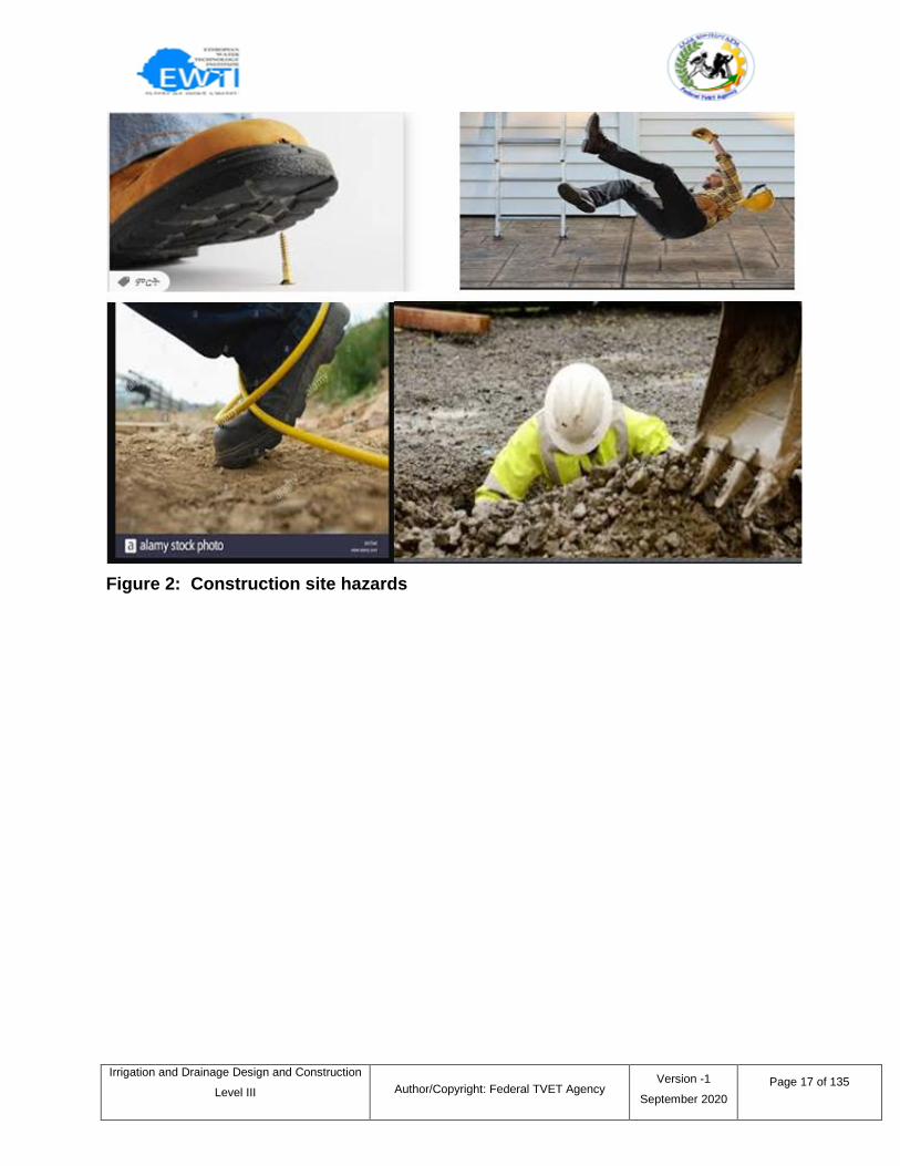
Figure 2: Construction site hazards
Irrigation and Drainage Design and Construction
Level III
Author/Copyright: Federal TVET Agency Version -1
September 2020
Page 18 of 135
Self-check 2 Written Test
1. Which one of the following is biological hazard
a. Fungi and mold b. Insect bites c. Bacteria and viruses d. All
2. Which one of the following is ergonomic hazard
a.Frequent lifting b. plants c. insects d. all
3.___ is any potential interference with the quality of life of your occupation that
causes health and safety risks.
a. Biological hazard b. workplace hazards c. fall d. all
4. During hazard identification which one of the following questions is best.
a. Can I come into contact with an energy source?
b. Can I come into contact with a hazardous substance?
c. Can I be struck by or strike against anything?
d. All
Short Answer Questions
Directions: Answer all the questions listed below. Use the Answer sheet provided in
the next page:
1. Define work place hazard.
2. Briefly describe common work place hazards.
3. List hazard identification steps.
4. Describe each hazard identification steps?
Note: Each question carries 3 points: Satisfactory rating - 24 points:
Unsatisfactory - below 12 points
You can ask your teacher for the copy of the correct answers.
Answer Sheet
Score = ___________
Rating: ___________
Name: _________________________ Date: _______________
I. Choose answer
1. ___ 2.____ 3. _____ 4. ______
Irrigation and Drainage Design and Construction
Level III
Author/Copyright: Federal TVET Agency Version -1
September 2020
Page 19 of 135
II. Short Answer Questions
1. _____________________________________________________________
2. ________________________________________________________________
3.____________________________________________________________________
4. ________________________________________________________________
Irrigation and Drainage Design and Construction
Level III
Author/Copyright: Federal TVET Agency Version -1
September 2020
Page 20 of 135
3.1 Introduction
Temporary diversion methods are commonly used to reroute water from a stream or
direct flows to a designated portion of the stream channel to allow for construction
activities to take place in the stream, along the banks, or beneath the active channel.
Temporary diversion methods are often required during the construction of detention
ponds, dams, in stream grade control structures, bank protection, utility installation, and
other activities, including maintenance, that require working in waterways.
3.2 Temporary Diversion Work
The primary purpose of all temporary diversion methods is to allow for construction to
occur in ―dry‖ or dewatered conditions, providing conveyance of stream discharges and
protecting water quality by passing upstream flows, up to a specified design event or
threshold, around the active construction zone. Temporary diversion methods include
temporary diversion channels, pump diversions (water is collected and pumped around
the construction activities), piped diversions that operate via gravity, coffer dams, and
other similar practices.
Selection and design of temporary diversion methods should consider many factors,
including the following.
Will construction of a temporary diversion cause greater environmental impacts?
Nature of surrounding land use, property ownership, and easements in the project
area.
Seasonal variations in stream hydrology (base flow versus peak flow).
Project duration and time of year during which construction will occur.
Public safety aspects.
Legal considerations, which are a function of many different factors such as
property ownership, history of localized flooding, or parties that will have interest in
project
Information sheet – 3 Making appropriate drainage and inflow diversion
arrangement.
Irrigation and Drainage Design and Construction
Level III
Author/Copyright: Federal TVET Agency Version -1
September 2020
Page 21 of 135
Design and Installation: The following describes the steps necessary for the design
and installation of temporary diversion methods.
1. Determine project duration.
2. Determine the time of year in which construction will occur.
3. Apply applicable sizing methodology and perform necessary calculations as
discussed below.
4. Determine appropriate method of diversion.
Channel Diversion--For smaller streams, construction of dams and detention
basins--or, as the site allows, a channel diversion--may divert the entire
waterway.
Berm or Coffer Dam--A berm or coffer dam is appropriate for streams of all
sizes to confine flow to one side of the stream.
Piped Diversion--A bypass pipe is generally appropriate for short-duration
projects with low base flows.
Pumped Diversion--A pumped diversion may be appropriate for short-duration
projects with low base flows. It may also be the only option where space for
the diversion is limited.
5. Consider developing an emergency action plan, as a precaution, for rapidly
removing equipment and materials.
Pump: a pumpis a device that moves fluids (liquidsorgases), or sometimes slurries, by
mechanical action, typically converted from electrical energy into Hydraulic energy.
Pumps operate via many energy sources, including manual operation, electricity,
engines, or wind power, and come in many sizes, from microscopic for use in medical
applications, to large industrial pumps.
Mechanical pumps serve in a wide range of applications such as pumping water from
wells, aquarium filtering, pond filtering and aeration, in the car industry for water-cooling
and fuel injection, in the energy industry for pumping oil and natural gas or for operating
cooling towers and other components of heating, ventilation and air conditioning
systems.
Irrigation and Drainage Design and Construction
Level III
Author/Copyright: Federal TVET Agency Version -1
September 2020
Page 22 of 135
Dewatering: Construction dewatering, unwatering, or water control are common terms
used to describe removal or draining groundwater or surface water from a riverbed,
construction site, caisson, or mine shaft, by pumping or evaporation. On a construction
site, this dewatering may be implemented before subsurface excavation for foundations,
shoring, or cellar space to lower the water table.
3.3 Maintenance
Remove debris and sediment from the channel and rebuild and stabilize the ridge
as needed.
Check outlets and make necessary repairs immediately.
If sediment traps are used as a performance enhancer, remove sediment from
traps when they are 50% full.
When the work area has been stabilized, remove the ridge and fill in the channel
to blend with the natural ground. Remove temporary slope drains and stabilize all
disturbed areas with vegetation or other erosion control practices.
Irrigation and Drainage Design and Construction
Level III
Author/Copyright: Federal TVET Agency Version -1
September 2020
Page 23 of 135
Self-check 3 Written Test
Short Answer Questions
Directions: Answer all the questions listed below. Use the Answer sheet provided in
the next page:
1. What is the purpose of installing temporary diversion work?
2. List the factors considered for design and installation of temporary diversion works.
3. List steps for design and installation of temporary diversion works.
4. List maintenance steps of temporary diversion works.
Note: Each question carries 5 points: Satisfactory rating - 20 points:
Unsatisfactory - below 10 points
You can ask your teacher for the copy of the correct answers.
Answer Sheet
Score = ___________
Rating: ___________
Name: _________________________ Date: _______________
Short Answer Questions
1.____________________________________________________________________
2.____________________________________________________________________
3.____________________________________________________________________
4. ____________________________________________________________________
Irrigation and Drainage Design and Construction
Level III
Author/Copyright: Federal TVET Agency Version -1
September 2020
Page 24 of 135
4.1 Introduction
Excavation is sometimes the only way of repairing seriously damaged components of
drains and canals. At Maintain Drains we offer at top quality excavation & repair
services. Our highly skilled a qualified team of professionals are ready to respond to
your drainage problem. Equipped with the latest technology, we can repair the drain
quickly, whilst also aiming for minimal disruption to you and your property
4.2 Excavation Tools and Machines in Construction
There are different types of soil excavation tools and machines used in construction.
Excavation of soil is necessary in construction point of view and it should be done by
hand tools or machineries based on the area of the land or depth of excavation. Now a
day, for the soil excavation there are so many equipment‘s are there and these are
classified into two types.
1. Hand tools
These are generally used for smaller depths of excavations in small areas. Man power
is required to operate these tools. The tools come under this category are explained
below.
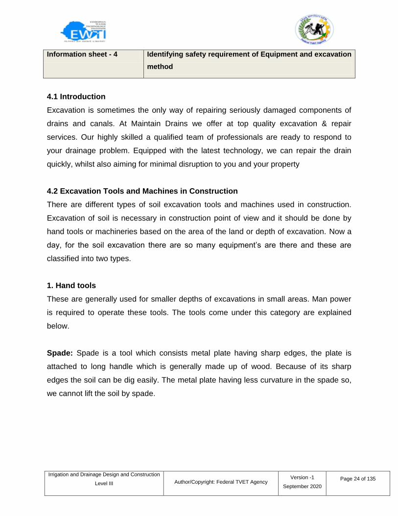
Spade: Spade is a tool which consists metal plate having sharp edges, the plate is
attached to long handle which is generally made up of wood. Because of its sharp
edges the soil can be dig easily. The metal plate having less curvature in the spade so,
we cannot lift the soil by spade.
Information sheet - 4 Identifying safety requirement of Equipment and excavation
method
Irrigation and Drainage Design and Construction
Level III
Author/Copyright: Federal TVET Agency Version -1
September 2020
Page 25 of 135
Figure 3: Spade
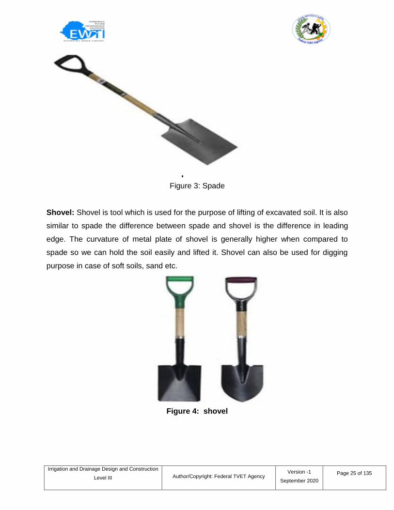
Shovel: Shovel is tool which is used for the purpose of lifting of excavated soil. It is also
similar to spade the difference between spade and shovel is the difference in leading
edge. The curvature of metal plate of shovel is generally higher when compared to
spade so we can hold the soil easily and lifted it. Shovel can also be used for digging
purpose in case of soft soils, sand etc.
Figure 4: shovel
Irrigation and Drainage Design and Construction
Level III
Author/Copyright: Federal TVET Agency Version -1
September 2020
Page 26 of 135
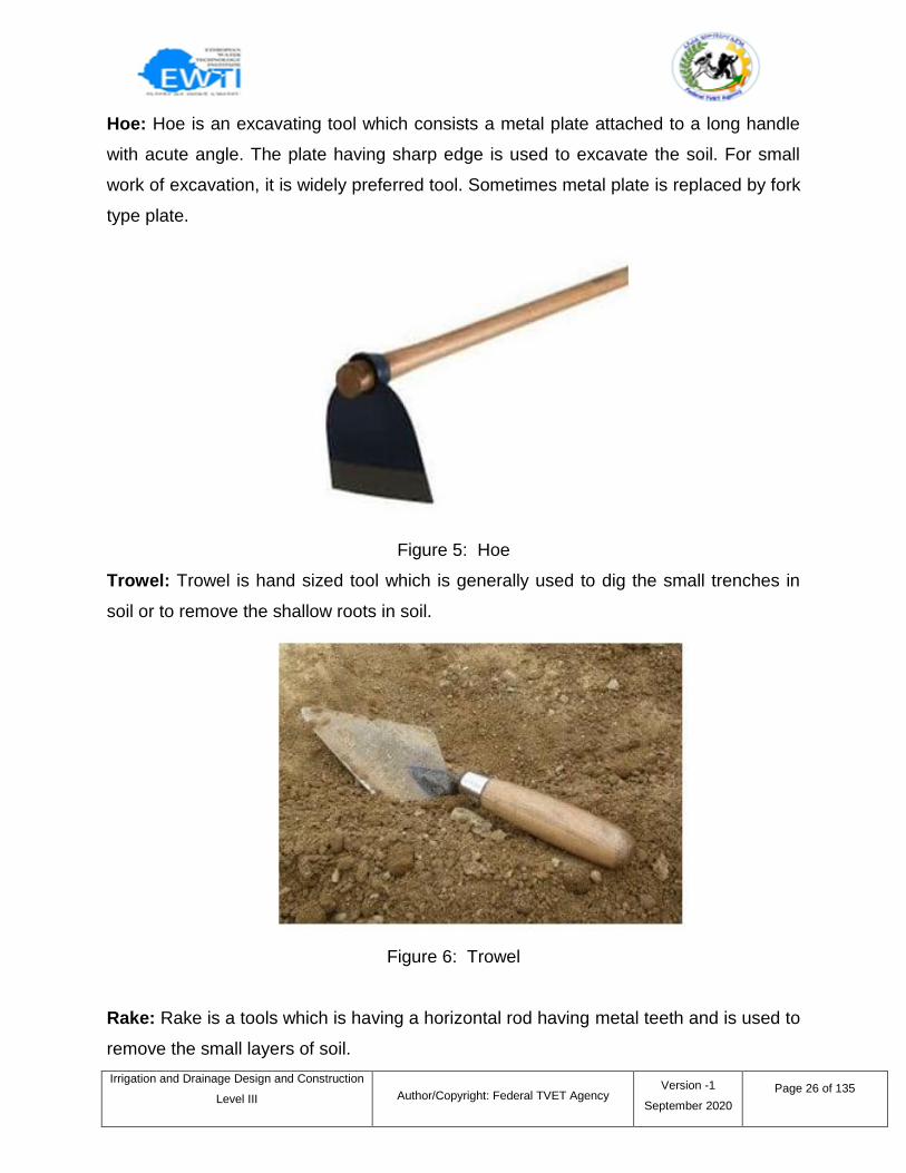
Hoe: Hoe is an excavating tool which consists a metal plate attached to a long handle
with acute angle. The plate having sharp edge is used to excavate the soil. For small
work of excavation, it is widely preferred tool. Sometimes metal plate is replaced by fork
type plate.
Figure 5: Hoe
Trowel: Trowel is hand sized tool which is generally used to dig the small trenches in
soil or to remove the shallow roots in soil.
Figure 6: Trowel
Rake: Rake is a tools which is having a horizontal rod having metal teeth and is used to
remove the small layers of soil.
Irrigation and Drainage Design and Construction
Level III
Author/Copyright: Federal TVET Agency Version -1
September 2020
Page 27 of 135
Figure 7: Rake
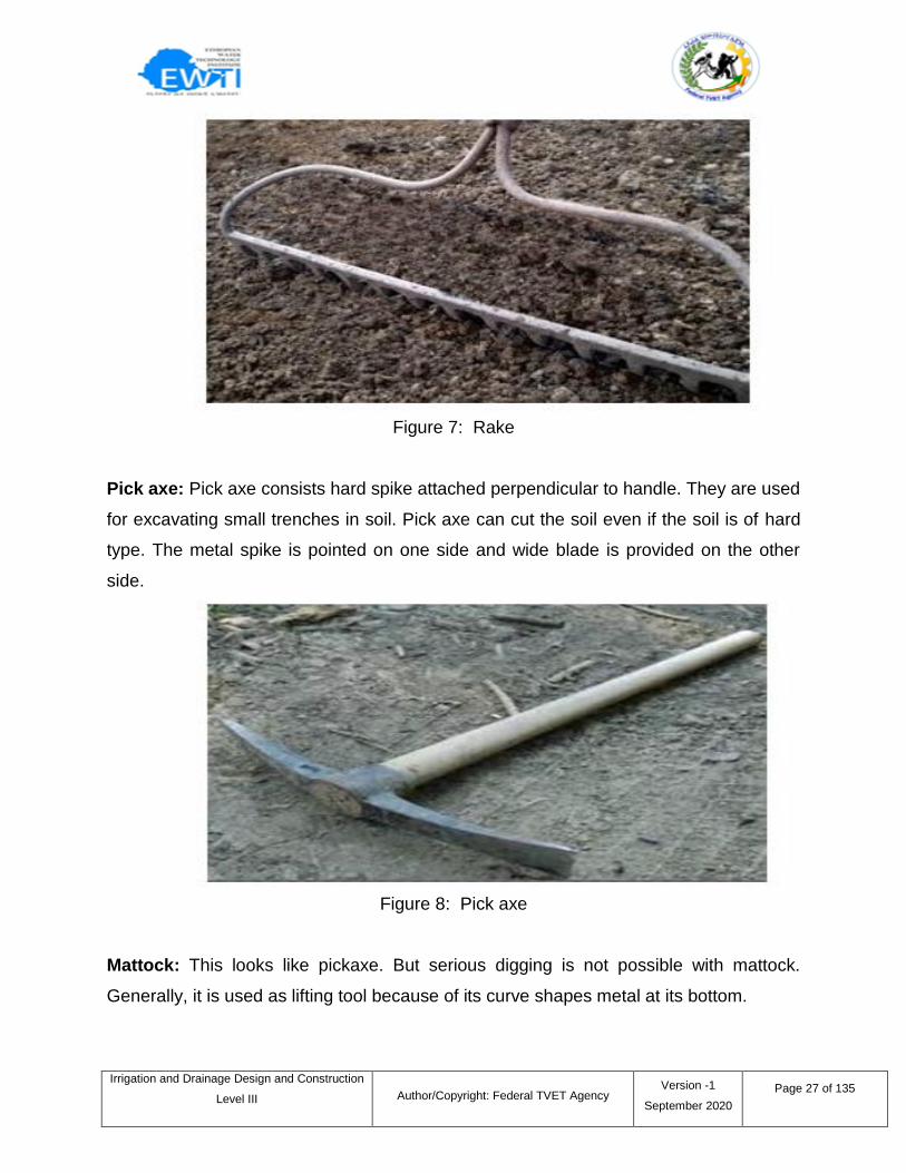
Pick axe: Pick axe consists hard spike attached perpendicular to handle. They are used
for excavating small trenches in soil. Pick axe can cut the soil even if the soil is of hard
type. The metal spike is pointed on one side and wide blade is provided on the other
side.
Figure 8: Pick axe
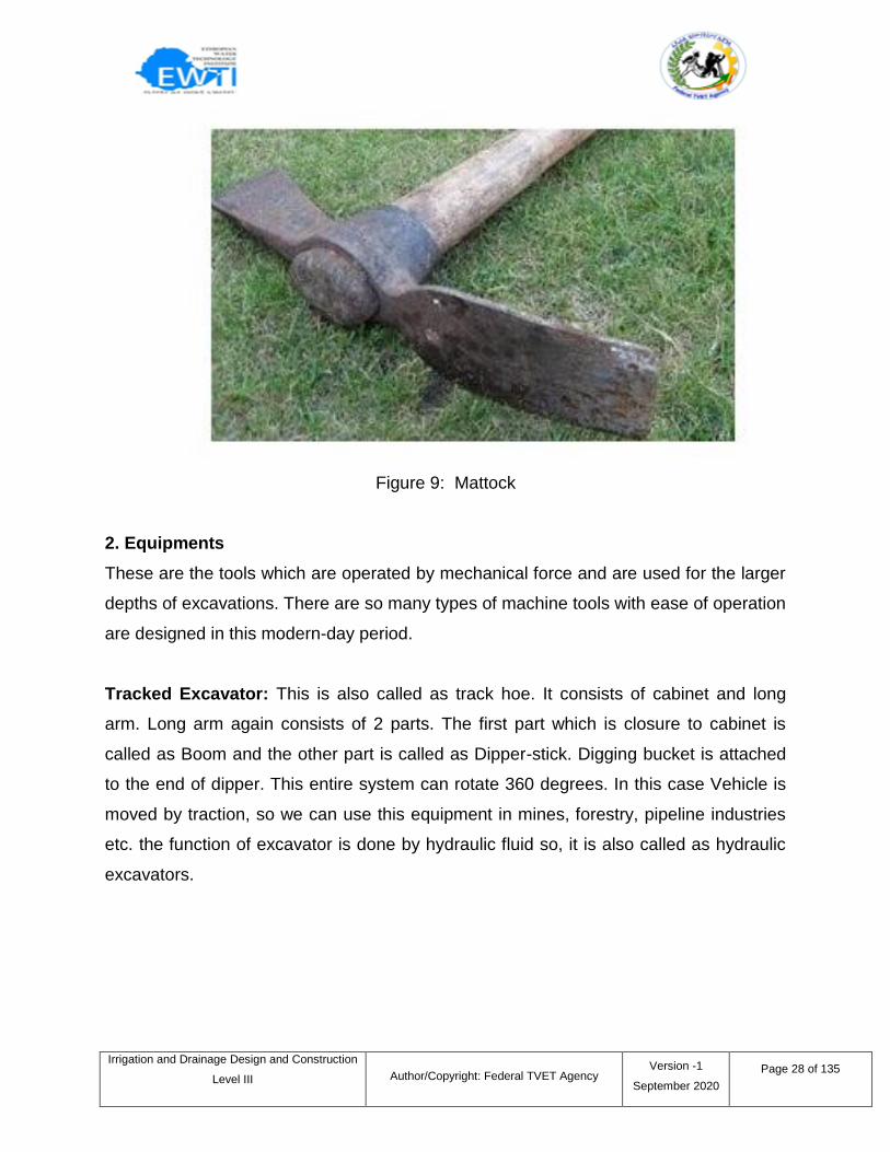
Mattock: This looks like pickaxe. But serious digging is not possible with mattock.
Generally, it is used as lifting tool because of its curve shapes metal at its bottom.
Irrigation and Drainage Design and Construction
Level III
Author/Copyright: Federal TVET Agency Version -1
September 2020
Page 28 of 135
Figure 9: Mattock
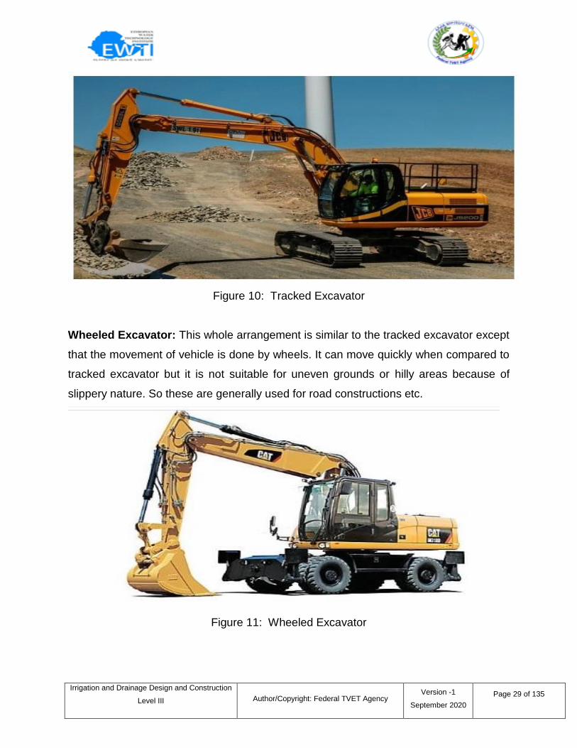
2. Equipments
These are the tools which are operated by mechanical force and are used for the larger
depths of excavations. There are so many types of machine tools with ease of operation
are designed in this modern-day period.
Tracked Excavator: This is also called as track hoe. It consists of cabinet and long
arm. Long arm again consists of 2 parts. The first part which is closure to cabinet is
called as Boom and the other part is called as Dipper-stick. Digging bucket is attached
to the end of dipper. This entire system can rotate 360 degrees. In this case Vehicle is
moved by traction, so we can use this equipment in mines, forestry, pipeline industries
etc. the function of excavator is done by hydraulic fluid so, it is also called as hydraulic
excavators.
Irrigation and Drainage Design and Construction
Level III
Author/Copyright: Federal TVET Agency Version -1
September 2020
Page 29 of 135
Figure 10: Tracked Excavator
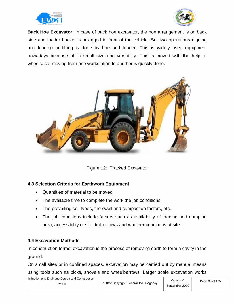
Wheeled Excavator: This whole arrangement is similar to the tracked excavator except
that the movement of vehicle is done by wheels. It can move quickly when compared to
tracked excavator but it is not suitable for uneven grounds or hilly areas because of
slippery nature. So these are generally used for road constructions etc.
Figure 11: Wheeled Excavator
Irrigation and Drainage Design and Construction
Level III
Author/Copyright: Federal TVET Agency Version -1
September 2020
Page 30 of 135
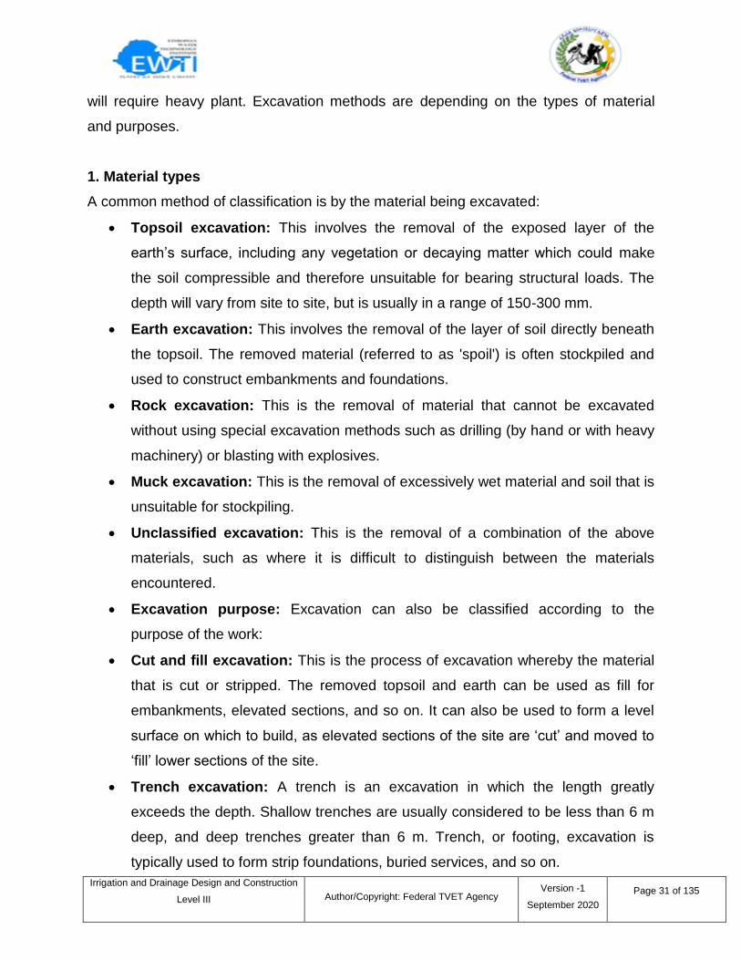
Back Hoe Excavator: In case of back hoe excavator, the hoe arrangement is on back
side and loader bucket is arranged in front of the vehicle. So, two operations digging
and loading or lifting is done by hoe and loader. This is widely used equipment
nowadays because of its small size and versatility. This is moved with the help of
wheels. so, moving from one workstation to another is quickly done.
Figure 12: Tracked Excavator
4.3 Selection Criteria for Earthwork Equipment
Quantities of material to be moved
The available time to complete the work the job conditions
The prevailing soil types, the swell and compaction factors, etc.
The job conditions include factors such as availability of loading and dumping
area, accessibility of site, traffic flows and whether conditions at site.
4.4 Excavation Methods
In construction terms, excavation is the process of removing earth to form a cavity in the
ground.
On small sites or in confined spaces, excavation may be carried out by manual means
using tools such as picks, shovels and wheelbarrows. Larger scale excavation works
Irrigation and Drainage Design and Construction
Level III
Author/Copyright: Federal TVET Agency Version -1
September 2020
Page 31 of 135
will require heavy plant. Excavation methods are depending on the types of material
and purposes.
1. Material types
A common method of classification is by the material being excavated:
Topsoil excavation: This involves the removal of the exposed layer of the
earth‘s surface, including any vegetation or decaying matter which could make
the soil compressible and therefore unsuitable for bearing structural loads. The
depth will vary from site to site, but is usually in a range of 150-300 mm.
Earth excavation: This involves the removal of the layer of soil directly beneath
the topsoil. The removed material (referred to as 'spoil') is often stockpiled and
used to construct embankments and foundations.
Rock excavation: This is the removal of material that cannot be excavated
without using special excavation methods such as drilling (by hand or with heavy
machinery) or blasting with explosives.
Muck excavation: This is the removal of excessively wet material and soil that is
unsuitable for stockpiling.
Unclassified excavation: This is the removal of a combination of the above
materials, such as where it is difficult to distinguish between the materials
encountered.
Excavation purpose: Excavation can also be classified according to the
purpose of the work:
Cut and fill excavation: This is the process of excavation whereby the material
that is cut or stripped. The removed topsoil and earth can be used as fill for
embankments, elevated sections, and so on. It can also be used to form a level
surface on which to build, as elevated sections of the site are ‗cut‘ and moved to
‗fill‘ lower sections of the site.
Trench excavation: A trench is an excavation in which the length greatly
exceeds the depth. Shallow trenches are usually considered to be less than 6 m
deep, and deep trenches greater than 6 m. Trench, or footing, excavation is
typically used to form strip foundations, buried services, and so on.
Irrigation and Drainage Design and Construction
Level III
Author/Copyright: Federal TVET Agency Version -1
September 2020
Page 32 of 135
The choice of technique and plant for excavating, supporting and backfilling the trench
depends on factors such as; the purpose of the trench, the ground conditions, the
trench location, the number of obstructions, and so on.
The common techniques that are used include:
Full depth, full length: Suitable for long narrow trenches of shallow depth, such as
pipelines and sewers.
Full depth, successive stages: Suitable for deep trenches where works can
progress in sequence, reducing the risk of collapse.
Stage depth, successive stages: Suitable for very deep trenches in confined
areas, deep foundations and underpinning.
Basement excavation: A basement is part of a building that is either partially or
completely below ground level.
Road excavation: This typically involves stripping topsoil and cut-and-fill.
Bridge excavation: This typically involves the removal of material for the footing
and abutments of bridges.
Dredging: Dredging is the process of excavating and removing sediments and
debris from below water level, typically from the bottom of lakes, rivers, harbors,
and so on.
Over excavation: Excavation that goes beyond the depth which is required for the
formation of a below ground structure due to the presence of unsuitable material
that must be removed.
4.5 Safety requirements
Trenching and Excavation Safety: Protective Systems
As with soil types, there are also different protective systems. Sometimes, the system is
established in the way the actual trench is dug out and shaped. Other times, extra
equipment and support are required. The most common types of protective systems
include sloping, shoring, and shielding.General Safe Excavation Practices:
Heavy equipment, tools, loads, and other materials should be kept away from
trench edges.
Surcharge loads must be kept at least 2 feet from trench edges.
Irrigation and Drainage Design and Construction
Level III
Author/Copyright: Federal TVET Agency Version -1
September 2020
Page 33 of 135
Underground utilities should be designated, properly marked, and understood by
workers.
Hard hats must be worn at all times in every trench and excavation work zone.
Barricade materials such as fencing and tape should be used to keep
unauthorized persons from walking near the excavation site.
Mark and locate utilities: Employers must ensure all gas, electrical and other
services are located and marked in and near the area to be excavated.
Adjacent structures: Constructors must prevent damage to adjacent structures
by engaging a professional engineer who must specify in writing the
precautions to be taken.
Soil strength: Determine the soil type to protect excavation walls from
collapsing.
Wall stability: Strip the wall of a trench or excavation of any loose rock or other
material, including ice, that may slide, roll or fall on a worker.
Equipment: Keep heavy equipment, excavated soil or rock and construction
material at least one meter away from the upper edges of the trench or
excavation.
Work space: Maintain a clear work space of at least 18 inches between the
wall of an excavation and any formwork, masonry or similar wall.
Fall protection: Provide a barrier at least 1.1 meters high at the topifan
excavation does not meet regulatory slope requirement and ismore than2.4
meters deep.
Protect yourself: Never enter a trench deeper than 1.2 meters unless the walls
are sound, made of solid rock, properly sloped, shored or protected by a
trench box. Never work alone in a trench.
Protective systems: Workers must be protected against trench or excavation
cave-ins and other hazards using three basic methods:
Sloping which involves cutting back trench walls at an angle, inclined
away from the excavation.
Irrigation and Drainage Design and Construction
Level III
Author/Copyright: Federal TVET Agency Version -1
September 2020
Page 34 of 135
Shoring which helps support trench and excavation walls to prevent
movement of soil, underground utilities, roadways and foundations.
Timber and hydraulic systems are the most commonly used supports to
shore up walls.
Prefabricated support systems which can prevent soil cave-ins.
"Competent person‖: Trenches and excavations must be inspected daily for
hazards, and when conditions change,beforeworkers enter them. This must be
done by a "competent person".
Entry and exit:Provide safe access and egress for workers at excavations by
means of ladders, steps, ramps, or other safe methods of entering or exiting.
Trenches must have ladders placed in the area protected by the support
system and be accessible in the event of a collapse.
Irrigation and Drainage Design and Construction
Level III
Author/Copyright: Federal TVET Agency Version -1
September 2020
Page 35 of 135
Self-check 4 Written test
I. Choose the best answer.
1. Which one is hand tool?
a. Shovel b. excavator c. pump d. all
2. Selection criteria for earthwork equipment
a. Quantities of material to be moved
b. The available time to complete the work the job conditions
c. The prevailing soil types, the swell and compaction factors
d. All
3. ____ the removal of the exposed layer of the earth‘s surface.
a. Topsoil excavation
b. Earth excavation
c. Rock excavation
d. All
4. ____ an excavation in which the length greatly exceeds the depth.
a. Trench b. excavation c. ditch d. All
5. ____ which involves cutting back trench walls at an angle, inclined away from the
excavation.
a. Shoring b. Sloping c. Prefabricated support systems d. all
II. Short Answer Questions
Directions: Answer all the questions listed below. Use the Answer sheet provided in
the next page:
1. Based on this lesson what is the function of excavation.
2. List types of hand tools used for excavation purpose.
3. List criteria for selecting excavation equipments.
4. Briefly describe common methods of excavation based on the material being
excavated.
5. Explain excavation safety requirements.
Irrigation and Drainage Design and Construction
Level III
Author/Copyright: Federal TVET Agency Version -1
September 2020
Page 36 of 135
Note: Each question carries 2 points: Satisfactory rating - 18 points:
Unsatisfactory - below 9 points
You can ask your teacher for the copy of the correct answers.
Answer Sheet
Score = ___________
Rating: ___________
Name: _________________________ Date: _______________
I. Choose answer
1. ___ 2. ____ 3. ____ 4. _____ 5. _____
II. Short Answer Questions
1.____________________________________________________________________
2.____________________________________________________________________
3.____________________________________________________________________
4. ____________________________________________________________________
5.____________________________________________________________________
Irrigation and Drainage Design and Construction
Level III
Author/Copyright: Federal TVET Agency Version -1
September 2020
Page 37 of 135
5.1 Introduction
PPE is required to reduce employees‘ exposuresto hazards when engineering or
administrativecontrols are not feasible or effective in reducingthese exposures to
acceptable levels. Employersmust determine all exposures to hazards in
theirworkplaces and determine if workers should usePPE for protection.If using PPE to
reduce employee exposure to hazards, start and maintain a PPE program including:
Methods to identify and evaluate workplacehazards and determine if issuing PPE
is an appropriate control measure;
Plan development to select, maintain andevaluate its use;
Training of employees using the PPE;
Program vigilance to determine its effectiveness in preventing employee injury or
illness.
We recommend the following guidelines for PPE use:
Wear hard hats for protection from falling orflying objects.
Maintain work shoes in good condition forsolid and secure footing;
Wear a warning vest in traffic areas;
Use proper eye and face protection when you have exposer.
Wear gloves when there is danger of burns,abrasions, cuts or lacerations.
Wear respirators approved by the NationalInstitute for Occupational Safety &
Healthwhere and when job hazards make them necessary.
Wear rubber boots, gloves and aprons whenexposed or in contact with raw
sewage ofwastewater systems. Provide sanitary washing facilities for cleanup.
5.2 Personal protective equipment
The term ‗personal protective equipment‘ (PPE) refers to a vast group of products (e.g.
safety helmets, safety footwear and harnesses, eye protection, gloves, high-visibility
Information sheet - 5 Selecting, using and fitting of Personal protective equipment
Irrigation and Drainage Design and Construction
Level III
Author/Copyright: Federal TVET Agency Version -1
September 2020
Page 38 of 135
clothing, etc.) designed with the aim to protect users against low-, medium- and high-
level hazards.
There are eight types of personal protective equipment critical for the defense of users
against hazards.
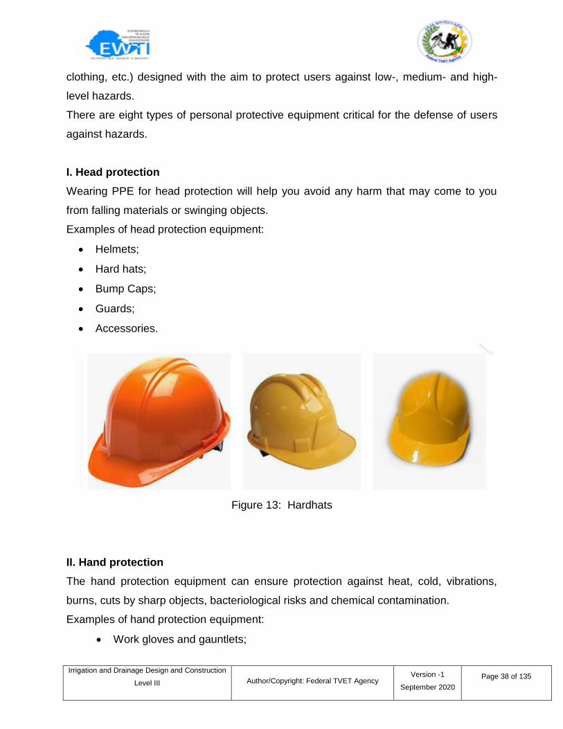
I. Head protection
Wearing PPE for head protection will help you avoid any harm that may come to you
from falling materials or swinging objects.
Examples of head protection equipment:
Helmets;
Hard hats;
Bump Caps;
Guards;
Accessories.
Figure 13: Hardhats
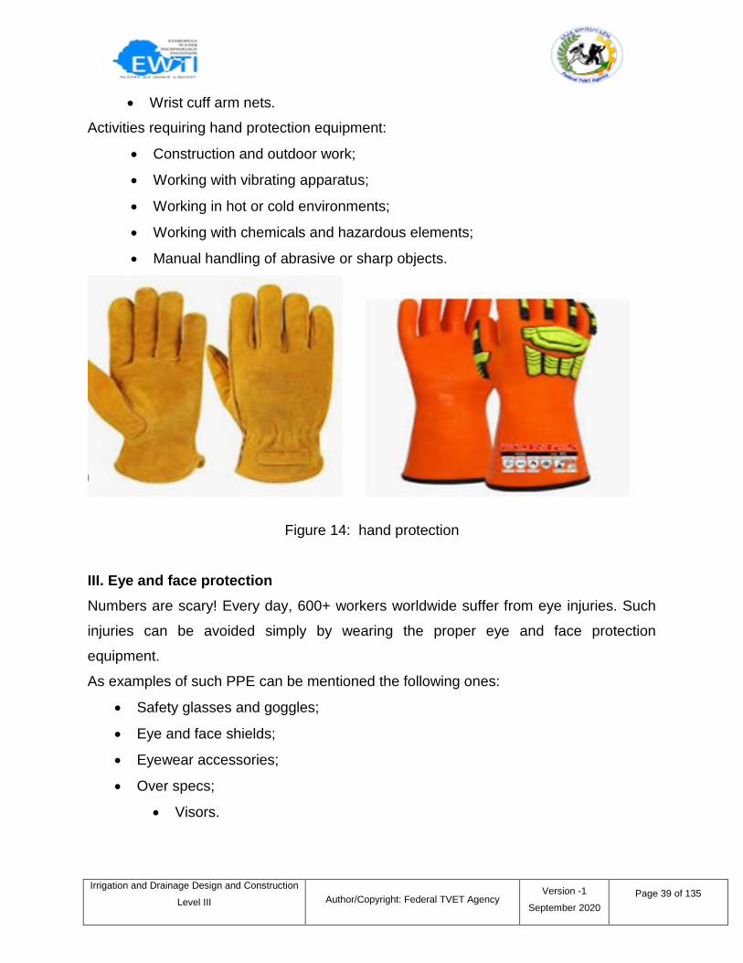
II. Hand protection
The hand protection equipment can ensure protection against heat, cold, vibrations,
burns, cuts by sharp objects, bacteriological risks and chemical contamination.
Examples of hand protection equipment:
Work gloves and gauntlets;
Irrigation and Drainage Design and Construction
Level III
Author/Copyright: Federal TVET Agency Version -1
September 2020
Page 39 of 135
Wrist cuff arm nets.
Activities requiring hand protection equipment:
Construction and outdoor work;
Working with vibrating apparatus;
Working in hot or cold environments;
Working with chemicals and hazardous elements;
Manual handling of abrasive or sharp objects.
Figure 14: hand protection
III. Eye and face protection
Numbers are scary! Every day, 600+ workers worldwide suffer from eye injuries. Such
injuries can be avoided simply by wearing the proper eye and face protection
equipment.
As examples of such PPE can be mentioned the following ones:
Safety glasses and goggles;
Eye and face shields;
Eyewear accessories;
Over specs;
Visors.
Irrigation and Drainage Design and Construction
Level III
Author/Copyright: Federal TVET Agency Version -1
September 2020
Page 40 of 135
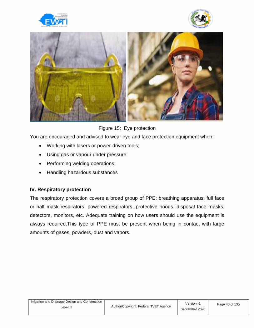
Figure 15: Eye protection
You are encouraged and advised to wear eye and face protection equipment when:
Working with lasers or power-driven tools;
Using gas or vapour under pressure;
Performing welding operations;
Handling hazardous substances
IV. Respiratory protection
The respiratory protection covers a broad group of PPE: breathing apparatus, full face
or half mask respirators, powered respirators, protective hoods, disposal face masks,
detectors, monitors, etc. Adequate training on how users should use the equipment is
always required.This type of PPE must be present when being in contact with large
amounts of gases, powders, dust and vapors.
Irrigation and Drainage Design and Construction
Level III
Author/Copyright: Federal TVET Agency Version -1
September 2020
Page 41 of 135
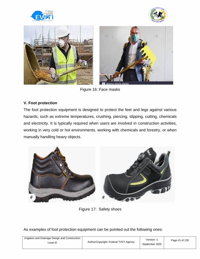
Figure 16: Face masks
V. Foot protection
The foot protection equipment is designed to protect the feet and legs against various
hazards, such as extreme temperatures, crushing, piercing, slipping, cutting, chemicals
and electricity. It is typically required when users are involved in construction activities,
working in very cold or hot environments, working with chemicals and forestry, or when
manually handling heavy objects.
Figure 17: Safety shoes
As examples of foot protection equipment can be pointed out the following ones:
Irrigation and Drainage Design and Construction
Level III
Author/Copyright: Federal TVET Agency Version -1
September 2020
Page 42 of 135
Safety boots and shoes;
Anti-static and conductive footwear.
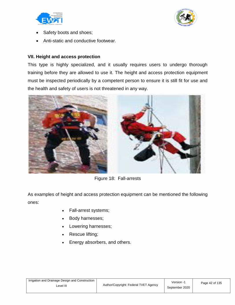
VII. Height and access protection
This type is highly specialized, and it usually requires users to undergo thorough
training before they are allowed to use it. The height and access protection equipment
must be inspected periodically by a competent person to ensure it is still fit for use and
the health and safety of users is not threatened in any way.
Figure 18: Fall-arrests
As examples of height and access protection equipment can be mentioned the following
ones:
Fall-arrest systems;
Body harnesses;
Lowering harnesses;
Rescue lifting;
Energy absorbers, and others.
Irrigation and Drainage Design and Construction
Level III
Author/Copyright: Federal TVET Agency Version -1
September 2020
Page 43 of 135
Self-check 5 Written Test
I. Choose the best answer.
1. _____a product with the aim to protect users against low-, medium- and high-level
hazards.
a. PPE b. chemicals c. protection d. all
2. Which one of the following is head protection.
a. Helmets b. Guards c. Hard hats d. All
3. Which activities requiring hand protection equipment.
a. Construction and outdoor work.
b. Working with vibrating apparatus.
c. Working in hot or cold environments
d. All
4. Which of the following is eye and face protection.
a. Visors
b. Safety glasses and goggles
c. Eye and face shields
d. All
II. Short Answer Questions
Directions: Answer all the questions listed below. Use the Answer sheet provided in
the next page:
1. What is the purpose of PPE?
2. List and describe major PPE types.
3. List the PPE application procedures.
Note: Each question carries 4 points: Satisfactory rating - 28 points:
Unsatisfactory - below 14 points
You can ask your teacher for the copy of the correct answers.
Answer Sheet
Irrigation and Drainage Design and Construction
Level III
Author/Copyright: Federal TVET Agency Version -1
September 2020
Page 44 of 135
Score = ___________
Rating: ___________
Name: _________________________ Date: _______________
Choose answer
1. ___ 2. ____ 3. ____ 4. ____ 5. _____
Short Answer Questions
1.____________________________________________________________________
2.____________________________________________________________________
3.____________________________________________________________________
Irrigation and Drainage Design and Construction
Level III
Author/Copyright: Federal TVET Agency Version -1
September 2020
Page 45 of 135
Tools and Equipment’s
Design document
Shovel, hoe, spade, Rake, pick axe, meter
Excavator (based on the size of excavation site)
Procedures
1. Get relevant data of work site including discharge rate of irrigation canal.
2. Select the feasible diversion type based on the site condition.
3. Design diversion work based on the inflow capacity.
4. setting out work
5. Finalize excavation and soil removal.
6. Make safe access and egress arrangements for personnel and equipment
7. Provide facility for safe disposal of unexpected excess water.
8. Prepare routine maintenance plan.
Operation Sheet 1 Making appropriate drainage and inflow diversion arrangement.
Irrigation and Drainage Design and Construction
Level III
Author/Copyright: Federal TVET Agency Version -1
September 2020
Page 46 of 135
LAP Test 1 Practical Demonstration
Name: _______________________________ Date: ______________
Time started: _________________________ Time finished _______________
Instructions: Given the necessary materials you are required to perform the following
tasks within 3 hour.
1. Making appropriate drainage and inflow diversion arrangement(3hr)
Irrigation and Drainage Design and Construction
Level III
Author/Copyright: Federal TVET Agency Version -1
September 2020
Page 47 of 135
This learning guide is developed to provide you the necessary information regarding the
following content coverage and topics:
Routine inspections of asset condition and operational capacity
Conducting routine inspection of work area
Identifying and correcting System faults
Identifying, selecting, placing and joining components of drainage system
Prefabricated drain sections
Construction of in situ Cast components
Removing of Debris, silt and obstructions
Performing preventative maintenance program
This guide will also assist you to attain the learning outcome stated in the previous
page. Specifically, upon completion of this Learning Guide, you will be able to –
Routine inspections of asset condition and operational capacity
Conducting routine inspection of work area
Identifying and correcting System faults
Identifying, selecting, placing and joining components of drainage system
Prefabricated drain sections
Construction of in situ Cast components
Removing of debris, silt and obstructions
Performing preventative maintenance program
InstructionSheet Learning Guide- 57: Maintain irrigation channels, drainage assets and
associated fittings.
Irrigation and Drainage Design and Construction
Level III
Author/Copyright: Federal TVET Agency Version -1
September 2020
Page 48 of 135
Learning Instructions:
1. Read the specific objectives of this Learning Guide.
2. Follow the instructions described below 3 to 4.
3. Read the information written in the information ―Sheet 1, Sheet 2, Sheet 3 and
Sheet 4‖inpage 49, 59, 63 and 82, 92respectively.
4. Accomplish the ―Self-check 1, Self-check 2, Self-check 3 and Self- check 4‖ -‖ in
page 57, 62, 80 and 91, 95 respectively
5. If you accomplish the self-checks, do operation sheet in page 96 and 97
6. LAP Test in page 99
Irrigation and Drainage Design and Construction
Level III
Author/Copyright: Federal TVET Agency Version -1
September 2020
Page 49 of 135
1.1 Introduction
Surface irrigation schemes typically include a large number of relatively low-cost assets,
of several different types and functions, spread over a large area. The fitness of an
asset to perform its function is assessed by field inspection. However, the assessment
method has been adapted for use by relatively unskilled staff (overseers). Since some
problems require experienced engineering judgment, a two-stage procedure has been
adopted. In the first stage, condition is assessed by relatively unskilled staff using
standard forms. Components which are rated Poor or Very Poor may require a second-
stage investigation by engineering staff.
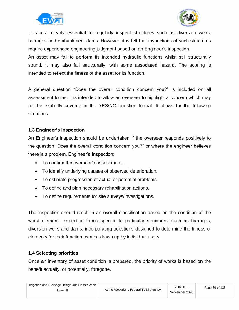
1.2 Assessing the Condition of assets
This section describes procedures for determining the condition of infrastructure,
condition being judged in terms of hydraulic effectiveness and structural integrity. The
final output of the Procedure defines priorities for work. Selected items can be detailed
and costed. Structures of principal importance such as diversion weirs, dams and
impounding embankments require formal inspections by experienced engineers.
Standard engineering inspection preformas have not been included in the Procedure,
but could be prepared by the user, if required.
Table 1: Basic structure types for condition assessment
Information sheet – 1 Routine inspections of asset condition
Irrigation and Drainage Design and Construction
Level III
Author/Copyright: Federal TVET Agency Version -1
September 2020
Page 50 of 135
It is also clearly essential to regularly inspect structures such as diversion weirs,
barrages and embankment dams. However, it is felt that inspections of such structures
require experienced engineering judgment based on an Engineer‘s inspection.
An asset may fail to perform its intended hydraulic functions whilst still structurally
sound. It may also fail structurally, with some associated hazard. The scoring is
intended to reflect the fitness of the asset for its function.
A general question ―Does the overall condition concern you?‖ is included on all
assessment forms. It is intended to allow an overseer to highlight a concern which may
not be explicitly covered in the YES/NO question format. It allows for the following
situations:
1.3 Engineer’s inspection
An Engineer‘s inspection should be undertaken if the overseer responds positively to
the question ―Does the overall condition concern you?‖ or where the engineer believes
there is a problem. Engineer‘s Inspection:
To confirm the overseer‘s assessment.
To identify underlying causes of observed deterioration.
To estimate progression of actual or potential problems
To define and plan necessary rehabilitation actions.
To define requirements for site surveys/investigations.
The inspection should result in an overall classification based on the condition of the
worst element. Inspection forms specific to particular structures, such as barrages,
diversion weirs and dams, incorporating questions designed to determine the fitness of
elements for their function, can be drawn up by individual users.
1.4 Selecting priorities
Once an inventory of asset condition is prepared, the priority of works is based on the
benefit actually, or potentially, foregone.
Irrigation and Drainage Design and Construction
Level III
Author/Copyright: Federal TVET Agency Version -1
September 2020
Page 51 of 135
1.4.1 System operation
Information will be obtained from discussions with operations staff, from the observation
of structures and water levels in the field, from review of operations manuals, and
review of original design criteria and assumptions, where these are available. To assess
the impact of scheme operation on cropping intensity and/or yields, and identify what
variations exist between intended and actual practice, the flow control methods and
water delivery pattern for which the scheme was originally design, must be defined.Ask
staff to describe actual operational practices. Consider:
Is rotational supply implemented?
How frequently are settings changed?
Which structures are monitored and adjusted?
Are water levels maintained at design level?
1.4.2 Inappropriate design
Are there areas of land within the scheme area that are out of command or receive
inadequate water due to insufficient or badly sited off-takes, or poor canal alignment?
Has incorrect or inappropriate design of any structure, canal reach or drain resulted in
insufficient conveyance capacity or the failure of the structure to function as required?
Check the following factors:
Canal embankment slopes too steep
Insufficient cross drainage
Insufficient escape capacity
High losses in distribution or field systems
1.4.3 Deterioration of System Infrastructure
Detailed information on deterioration of infrastructure, and its likely impact on hydraulic
performance, will be obtained using the condition assessment procedure. Early,
discussions with operations staff can indicate the location of problems arising from
structural deterioration. Information obtained in this way should be cross-checked
through the condition assessment procedure and localized studies of hydraulic
Irrigation and Drainage Design and Construction
Level III
Author/Copyright: Federal TVET Agency Version -1
September 2020
Page 52 of 135
performance, where these are required. Does the condition of any component of the
irrigation or drainage networks restrict conveyance capacity, threaten structural stability
or otherwise lead to reduced water supply or flooding?
A drainage plan indicates the location and layout of lateral and main drains, outfalls,
surface water inlets and other structures in the field. It is a very important document to
use for future maintenance. Keep this document with the property deed, so that even if
the property ownership changes, the drainage information are kept with the farm.
A good drainage plan includes the following:
Date of construction
Name of installer (i.e., contractor or landowner)
Identification of any changes made during installation from the original
plan
Lateral spacing, size, depth, grade, footage and material
Main location, material, size, depth, grade and capacity
Details of any construction problems encountered during the installation
Location of all outfalls, surface water inlets and other structures
Location of utilities, sand pockets, springs, etc., that may affect future
maintenance
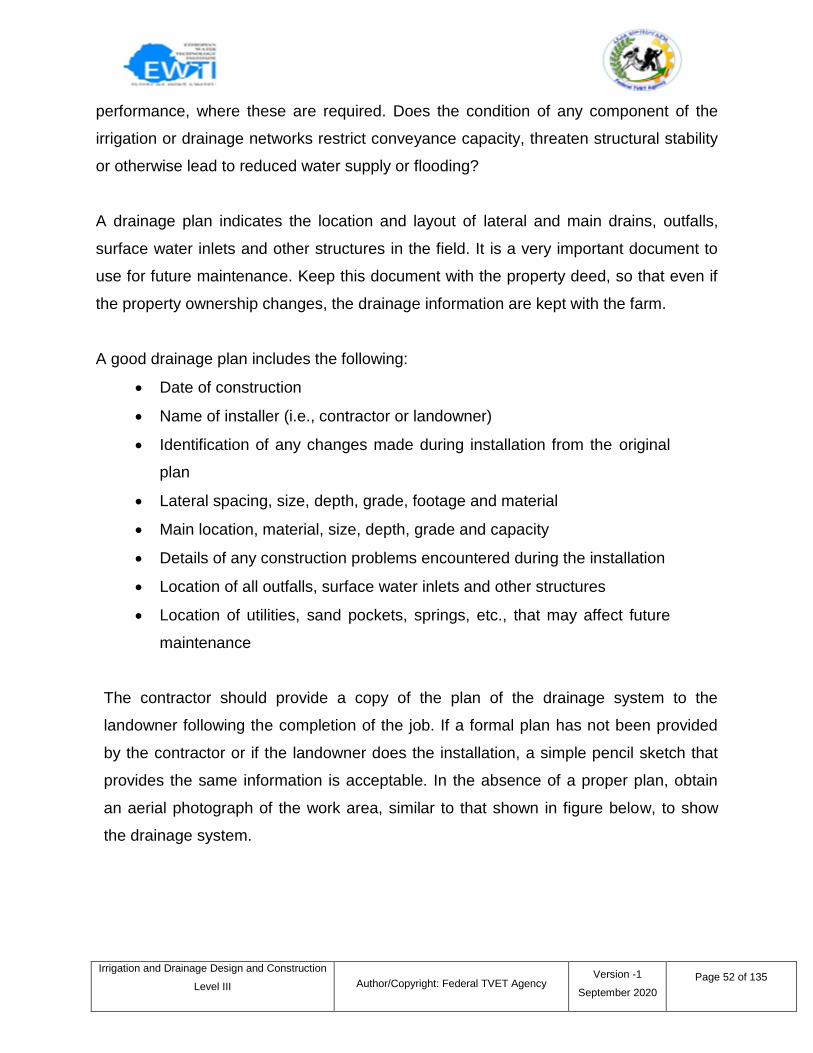
The contractor should provide a copy of the plan of the drainage system to the
landowner following the completion of the job. If a formal plan has not been provided
by the contractor or if the landowner does the installation, a simple pencil sketch that
provides the same information is acceptable. In the absence of a proper plan, obtain
an aerial photograph of the work area, similar to that shown in figure below, to show
the drainage system.
Irrigation and Drainage Design and Construction
Level III
Author/Copyright: Federal TVET Agency Version -1
September 2020
Page 53 of 135
.
Figure 19: Drainage System layout
Using the drainage plan as a guide, locate, inspect and mark all outfalls and surface
water inlets for reference when spreading nutrients on the property and for future
maintenance. Use a durable, permanent marker that is highly visible above crops and
tall grass. Ensure the workmanship of the system is good, as there will be limited time to
access the warranty period provided by the contractor, typically one year following
installation.
Confirm that all surface water inlets are fitted with a proper guard or grate to keep debris
and trash out of the subsurface drainage system. Ensure that a grate or rodent guard is
installed on all outfall pipes to prevent unwanted entry by burrowing animals such as
rodents, muskrats, rabbits and foxes. Check for burrowing animal activity around the
outfalls; if any signs exist, arrange to have the animals legally removed.

Irrigation and Drainage Design and Construction
Level III
Author/Copyright: Federal TVET Agency Version -1
September 2020
Page 54 of 135
Figure 20: Drainage outlet
The water that discharges from the outfall can cause erosion in the receiving drainage
channel or natural watercourse. Check to see if the contractor has installed sufficient
erosion protection to prevent this from happening.
Figure 21: Drainage outlet
It is important that the drainage system is periodically inspected and maintained over its
life span. The ideal time to inspect the system is in the spring, late fall and after a
significant rainfall event – when the soil is wet and the drains are running.
Irrigation and Drainage Design and Construction
Level III
Author/Copyright: Federal TVET Agency Version -1
September 2020
Page 55 of 135
Prompt repair of any noted issues will ensure that the system is always in good working
order and will prevent a more serious issue from developing.
Remember to make records of any maintenance/repairs and changes to the system on
the drainage plan. This will ensure that there is always an accurate plan of the system
for future inspection and maintenance.
Check for any signs of erosion of the drainpipe trench following rain events, especially
in the first few years. Inspect the mains and laterals a couple of days after a heavy
rainfall to look for any signs of ponding or excessive wet spots in your field. This may
indicate that a blocked drain exists and will need to be repaired.
Uniformity of crop growth is another good indicator of a properly functioning drainage
system. Ideally, the field should dry evenly and produce similar yields. Watch for
changes in crop yield in different areas of the field annually to see if there is a slower
developing problem in the drainage system that may need repair. Take periodic aerial
photographs of the farm to get an overview of the drainage system and to identify
potential drainage problems.
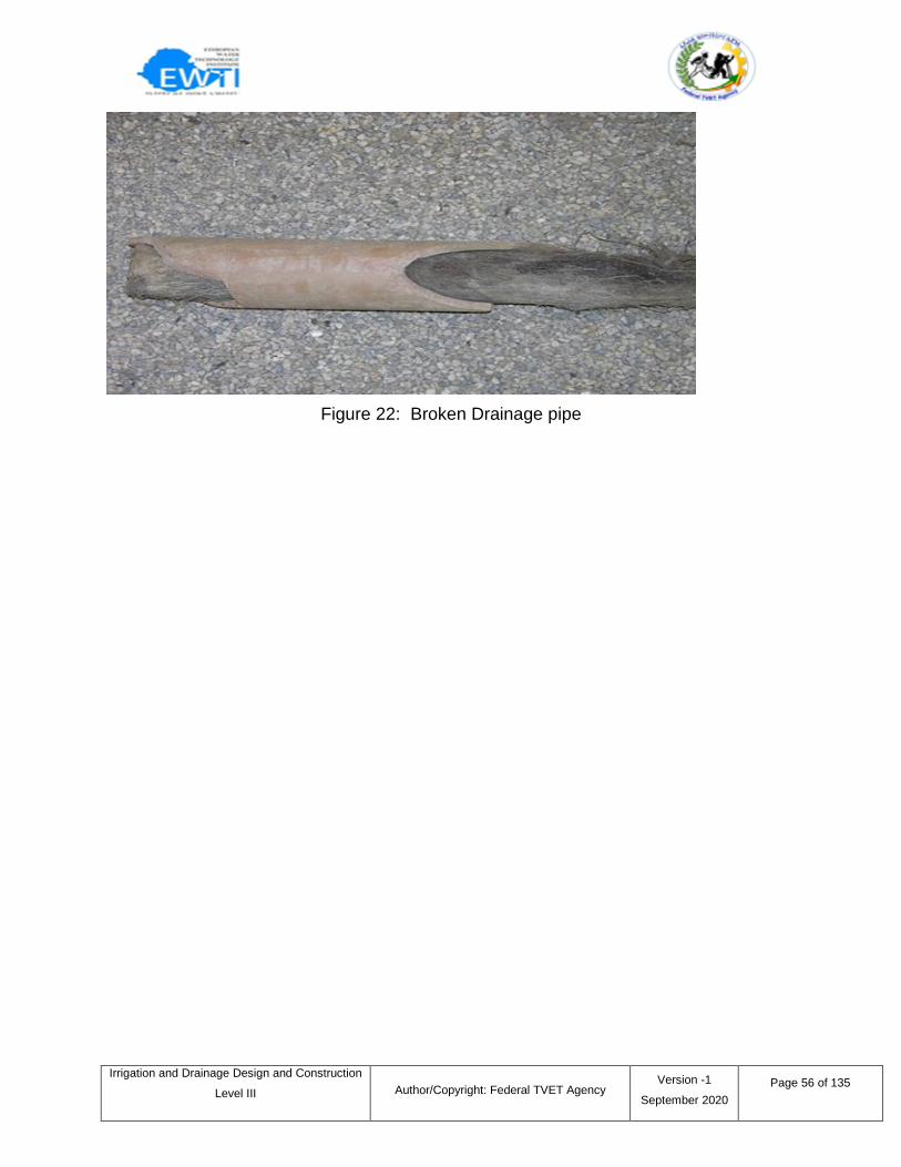
When drains get plugged, water rises to the surface at the point of the water stoppage.
Dig up the drain at the wet spot and repair it. Mark any locations of concern and contact
a licensed contractor to complete the repair as soon as reasonably possible. If the fields
are wet, it may be better to wait for drier conditions to make the repairs to avoid
damaging the soil structure.
Irrigation and Drainage Design and Construction
Level III
Author/Copyright: Federal TVET Agency Version -1
September 2020
Page 56 of 135
Figure 22: Broken Drainage pipe
Irrigation and Drainage Design and Construction
Level III
Author/Copyright: Federal TVET Agency Version -1
September 2020
Page 57 of 135
Self-check 1 Written Test
I. Choose the best answer
1. Which one of the following is engineer‘s inspection
a. Confirming the overseer‘s assessment
b. Identifying underlying causes of observed deterioration
c. estimating progression of actual or potential problems
d. All
2. Which of the following is a point used to identify wrong design of a system.
a. Insufficient cross drainage
b. Canal embankment slopes are slightly steep.
c. sufficient escape capacity
d. No losses in distribution
3.. ____indicates the location and layout of lateral and main drains, outfalls, surface
water inlets and other structures in the field.
a. Drainage plan b. irrigation plan c. laterals d. all
4. Which is basic structure needs routine inspection
a. Drain b. syphon c. canal reaches d. all
II. Short Answer Questions
Directions: Answer all the questions listed below. Use the Answer sheet provided in
the next page:
1. What the difference between overseer‘s inspection and engineer‘s inspection?
2. List basic irrigation structures need routine inspection.
3. List factors considered operational efficiency of irrigation system.
4. What is the benefit of work plan on inspection work.
Note: Each question carries 3 points: Satisfactory rating - 6points:
Unsatisfactory - below 6 points
You can ask your teacher for the copy of the correct answers.
Answer Sheet
Irrigation and Drainage Design and Construction
Level III
Author/Copyright: Federal TVET Agency Version -1
September 2020
Page 58 of 135
Score = ___________
Rating: ___________
Name: _________________________ Date: _______________
Choose answer
1.. ___ 2.. ___ 3.. ____ 4.. ____
Short Answer Questions
1.____________________________________________________________________
2.____________________________________________________________________
3.____________________________________________________________________
4. ____________________________________________________________________
Irrigation and Drainage Design and Construction
Level III
Author/Copyright: Federal TVET Agency Version -1
September 2020
Page 59 of 135
2.1 Introduction
Construction projects involve the co-ordination of a great number of people, materials
and components. Regular inspection is a crucial part of ensuring that the works
progress as intended, both in terms of quality and compliance. Inspections will be
carried out for a number of different purposes throughout the duration of a project.
The inspection process is separate from the contractor's own supervision of the works.
Inspection is carried out purely to give an independent view of the works either for the
client or a third party, the term supervision might imply taking some responsibility for the
works, when in fact contractual responsibility lies with the contractor.
2.2 Quality and progress
Inspection ofthe maintenanceworks will be carried out as they proceed
toverifycompliancewith the requirements of thecontract documents. Site
inspectors(orclerks of works) may be provided as an additionalserviceby the
existingconsultant team, or could be newappointments.They may be basedon
sitepermanently or may make regular visits. Specialistinspectionsmay also be
necessary for specific aspects of theprojectsuch as; theclient'senvironmental policy,site
waste management plan,accessibility, and so on.
Site inspectorsprovide an independent assessment of theworksand will
generallyreportto thecontract administrator. They are likely to keep asitediary,
attendconstruction progress meetingsand to produce regular writtenreports. They had
limitedpowerother than to inspect; they could condemn work
Site inspector
Specificinspectionsmay also be carried out during theconstruction phaseas part of the
generalcontract administrationprocess:
Condition surveysof neighboringstructuresprior tocommencementof theworks.
Information sheet – 2 Conducting routine inspection of work site
Irrigation and Drainage Design and Construction
Level III
Author/Copyright: Federal TVET Agency Version -1
September 2020
Page 60 of 135
Regularvaluationinspectionsto assessprogressof theworksin order tovalueinterm
payments.
Witnessingcommissioning.
Inspection prior tocertificationofpractical completion.
Inspectionafterhandoverof thesiteto theclient on certificationofpractical completion.
Inspection the end of thedefects liability periodto prepare a schedule.
Inspectiononcompletionof therecitificationofdefectsset out on theschedule of
defects.
consultants generally have a responsibility to provide periodicinspectionunder the terms
of theirconditionsof engagement.
2.3 Health and safety
Inspections are also necessary to ensurecompliancewithhealth and safety. These can
be internalinspectionscurried out by thecontractor,third partyaudits or
externalinspectionsby theHealth and Safety executive.
Health and safety inspectionsmay be necessary in relation to:
Prevention of falls andpersonal fall protection systems.
Work at height.
Workplatforms such asscaffoldand mobile platforms.
Laddersand stepladders.
Personal protectionequipment, including head protection.
Plant, vehicles and otherequipment.
Storage.
Siteconditionsand order.
Avoidance of obstructions.
Prevention of unauthorizedaccess to thesite.
It is important thatinspectiontiming and frequency is properly organized, that
properreportsare prepared and that action is taken if necessary.
Inspectionreportsmight contain the following information:
Details of the person making the report.
Irrigation and Drainage Design and Construction
Level III
Author/Copyright: Federal TVET Agency Version -1
September 2020
Page 61 of 135
Details of the person theinspectionwas carried out for.
Location ofthe inspection.
Date and time of the inspection.
Description of the nature of the inspection.
Detailsofhealth and safetyrisksidentified.
Detailsof any action taken.
Detailsof any further action required.
Self-check 2 Written Test
Irrigation and Drainage Design and Construction
Level III
Author/Copyright: Federal TVET Agency Version -1
September 2020
Page 62 of 135
Short Answer Questions
Directions: Answer all the questions listed below. Use the Answer sheet provided in
the next page:
1. Briefly describe the inspection of the maintenance works.
2. List components of inspection reports.
3. List the concerning areas of health and safety inspection.
Note: Each question carries 4 points: Satisfactory rating - 12 points:
Unsatisfactory - below 6 points
You can ask your teacher for the copy of the correct answers.
Answer Sheet
Score = ___________
Rating: ___________
Name: _________________________ Date: _______________
Short Answer Questions
1.____________________________________________________________________
2.____________________________________________________________________
3.____________________________________________________________________
Information sheet – 3 Identifying and correcting System faults
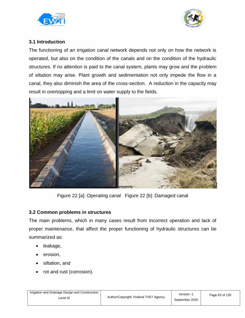
Irrigation and Drainage Design and Construction
Level III
Author/Copyright: Federal TVET Agency Version -1
September 2020
Page 63 of 135
3.1 Introduction
The functioning of an irrigation canal network depends not only on how the network is
operated, but also on the condition of the canals and on the condition of the hydraulic
structures. If no attention is paid to the canal system, plants may grow and the problem
of siltation may arise. Plant growth and sedimentation not only impede the flow in a
canal, they also diminish the area of the cross-section. A reduction in the capacity may
result in overtopping and a limit on water supply to the fields.
Figure 22 [a]: Operating canal Figure 22 [b]: Damaged canal
3.2 Common problems in structures
The main problems, which in many cases result from incorrect operation and lack of
proper maintenance, that affect the proper functioning of hydraulic structures can be
summarized as:
leakage,
erosion,
siltation, and
rot and rust (corrosion).
Irrigation and Drainage Design and Construction
Level III
Author/Copyright: Federal TVET Agency Version -1
September 2020
Page 64 of 135
Problems such as the disappearance of movable parts from structures or vandalism and
demolition are difficult to prevent, but they can be minimized by involving farmers in
canal operation and maintenance, and by cultivating the sentiment that structures are a
communal resource and therefore proper maintenance is a responsibility of the
community.
Leakage and erosion can be the result of poor design or construction, such as:
Walls may be too thin,
Foundations of structures may be too weak,
Materials used, such as the blocks from which a structure is made, may not be
strong enough for the purpose,
The concrete mix used in constructions may be too sandy,
Back-fill may not have been compacted sufficiently, or
The structure may not be properly connected to the canal.
The most common problems seen in structures are leakage, erosion, siltation, rot and
rust.
Leakage: The water level upstream of a structure is higher than the downstream
water level. Therefore, water may search for another way underneath or along
the structure, or even through a crack in the bottom or sides of the structure to
this lower level. The moment that water has found a small path there is a
leakage problem, and at the same time the beginning of an erosion problem.
Leaking water will enlarge the path by washing out the soil and so the leakage
will increase. Finally, the structure will collapse if the process is not stopped.
The upstream water level is so high that water can flow along the dam. If no
action is taken to remedy this the structure can be undermined by erosion and
will collapse.
To avoid such a problem, the structure can be equipped with vertical cut-offs.
They hinder the water flow along and underneath the structure. The cut-offs are
Irrigation and Drainage Design and Construction
Level III
Author/Copyright: Federal TVET Agency Version -1
September 2020
Page 65 of 135
part of a structure and can be driven into the bed and the embankments of a
canal.The intake structure is provided with cut-offs. They are dug deep into the
canal banks and into the canal bed. The drop structure is also equipped with cut-
offs. After installation, the earth of the canal banks around the cut-offs should be
well compacted.
Erosion: Sections of an unlined canal immediately downstream of a structure or
downstream of a lined canal section often suffer from erosion. Downstream of a
structure the canal bed may suffer from a water jet that flows through a gate or
pipe, or it will be caved in by water that spills over a weir. In both situations a
stilling basin is needed to dissipate the energy of the incoming water. The basin
should be constructed immediately downstream of the weir or pipe. It is usually
part of the structure.The transition from a lined section of a canal to an unlined
section is also a risk zone. If no care is taken, the lining will be undermined and
will finally collapse.
Siltation: The deposition of soil and debris can affect the functioning of a
structure. If, for instance, a stilling basin collects soil deposits the available water
mass diminishes and energy dissipation will be less effective. Similarly, in the
case of soil deposits in a flow division box, the division of the flow will be less
accurate due to changes in flow velocities and water levels.The same applies for
intake structures, such as the pumping station. Large volumes of sand in the
intake chamber of the pumps causes damage to the pumps and will lead to sand
deposits in the canal system too. Siltation is difficult to avoid.
Depending on the local conditions, large sand traps could be constructed at the upper
end of the main canal.
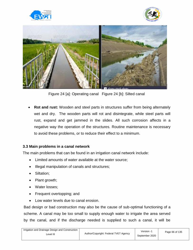
Irrigation and Drainage Design and Construction
Level III
Author/Copyright: Federal TVET Agency Version -1
September 2020
Page 66 of 135
Figure 24 [a]: Operating canal Figure 24 [b]: Silted canal
Rot and rust: Wooden and steel parts in structures suffer from being alternately
wet and dry. The wooden parts will rot and disintegrate, while steel parts will
rust, expand and get jammed in the slides. All such corrosion affects in a
negative way the operation of the structures. Routine maintenance is necessary
to avoid these problems, or to reduce their effect to a minimum.
3.3 Main problems in a canal network
The main problems that can be found in an irrigation canal network include:
Limited amounts of water available at the water source;
Illegal manipulation of canals and structures;
Siltation;
Plant growth;
Water losses;
Frequent overtopping; and
Low water levels due to canal erosion.
Bad design or bad construction may also be the cause of sub-optimal functioning of a
scheme. A canal may be too small to supply enough water to irrigate the area served
by the canal, and if the discharge needed is supplied to such a canal, it will be
Irrigation and Drainage Design and Construction
Level III
Author/Copyright: Federal TVET Agency Version -1
September 2020
Page 67 of 135
excessive and water will overtop. Also the water level in a canal may have been
wrongly determined, and if it is too low water may not enter the fields by gravity. Check
structures or even pumps will then be needed to supply the fields with sufficient water.
If the minimum required free board levels are not respected, canals can easily overtop
in emergencies. Canal slopes which are too steep may suffer erosion from high flow
velocities. When construction materials are not well chosen, canals may collapse. Lack
of maintenance of the canal network will also cause severe problems.
Three of the problems mentioned above, and which are of a technical character, are
described below in detail: water losses; overtopping; and canal erosion.
3.3.1 Water losses
A well designed and constructed canal system transports water from the source to the
farmers‘ fields with a minimum amount of water loss. However, water losses will occur
and can seriously reduce the efficiency of water delivery. Water may be lost by
seepage, leakage, or both.
Seepage: Water that seeps through the bed and sides of a canal will be lost for
irrigation. This so-called ‗seepage loss‘ can be significant where a canal is constructed
from material which has a high permeability.
Seepage can be reduced by:
reinforcing the canal bank or
sealing or lining the canal bed and sides.
Leakage:Water may also be lost for irrigation by leakage. This water does not seep,
but flows through larger openings in the canal bed or sides.
Leaks can develop in several ways:
by rat or termite holes in a canal bed or sides;
eroded and washed canal bank;
small tunnels started by seepage water in a badly compacted or sandy section of
a canal bank;
Irrigation and Drainage Design and Construction
Level III
Author/Copyright: Federal TVET Agency Version -1
September 2020
Page 68 of 135
seepage around structures, leading to severe leakages;
gates which are not tightly sealed;
cracked concrete canal linings, or joints that are not tightly sealed; or
torn asphalt or plastic lining.
Leakage often starts on a small scale, but the moment that water has found a way
through a canal embankment a hole will develop through which water will leak. If the
leakage is not stopped in time, the tunnel becomes larger and the canal bank may be
washed away at a certain moment.
In the case of a lined canal, the canal foundation may be undermined after some time
and the canal will collapse. Serious leakage can be avoided when the canal system is
inspected frequently and when repairs are carried out immediately. The longer a hole
or crack is left, the larger it will become.
3.3.2 Overtopping
Water in a canal may rise unexpectedly due to several reasons:
The incoming flow through the canal off take may be much greater than the canal
capacity;
Obstacles such as stones, blocks or plant growth in the canal may dam up the
water
Outlets from a canal may be closed which should be open;
rain or other water may be draining into the irrigation canal; or
Overtopping causes erosion of the canal banks and may lead to serious breaches. It
can be avoided by improving the operation of the system.
To prevent overtopping, which can happen even in the best irrigation systems, a
spillway - also called an emergency outlet - can be installed in the canal bank so that
excess flow can be spilled without harming the canal.
3.3.3 Canal erosion
The sides and bed of an unlined canal are sometimes badly attacked by scouring water.
This process is called erosion. Canal bends and sections downstream of structures in
Irrigation and Drainage Design and Construction
Level III
Author/Copyright: Federal TVET Agency Version -1
September 2020
Page 69 of 135
particular are susceptible to erosion, since local flow velocities can be very high and the
direction of flow changes suddenly, causing turbulence.
The embankments have collapsed and the cross-section no longer has its original
shape: it has become irregular. The canal banks have become smaller and the bed is
wider than before. When the embankments of a canal are not very solid, erosion can
result in leakage. Another problem is that the eroded soil will be deposited, known as
siltation, in structures downstream of the eroded canal section. This may cause a
malfunctioning of the structures and causing the flow to overtop the bank. Erosion by
water can be prevented by:
Reducing the flow velocity, and
Making the inner canal banks more stable,
Lining may be a solution.
Wetting and drying of the earth embankments may also cause the banks to crack.
Cracks can become small gullies through the process of erosion.
3.4 Maintenance work of irrigation structures
A properly designed and constructed hydraulic structure functions well for as long as it
is operated well and maintained with care. That means that there is neither leakage nor
erosion, that the channels and structures are clean, and that there are no rusty or rotten
movable parts in the structures.
To achieve such a situation, regular maintenance is required, and even if maintenance
is well carried out, repairs may be needed after some time.
Minor problems in structures, like a leakage or rusty iron parts, may become important if
they are neglected. Frequent inspections and regular maintenance will help limit any
damage.
3.4.1 Inspection
Irrigation and Drainage Design and Construction
Level III
Author/Copyright: Federal TVET Agency Version -1
September 2020
Page 70 of 135
A canal system, and in particular the structures, can be safeguarded from problems
such as leakage, erosion, siltation, rot and rust by regular inspection and immediate
repair action. Since the canals are inspected regularly, structures can be inspected at
the same time. This makes it possible quickly to spot the beginning of leakage, erosion
or rust. A quickly executed repair will stop the problem while it is still a small one, and
before it escalates into serious damage. Inaccessible structures and lots of plant
growing on the canal embankments make inspection time-consuming, and it will also be
difficult to see water leaking if the walls of a structure are hidden from view.
3.4.2 Maintenance
Maintenance of structures consists of two main activities:
• Cleaning and de-silting, and
• Painting and lubricating.
Cleaning and de-silting:Sand deposits and plant growth can cause changes in flow
velocity through structures, and so the functioning of the structure will be less effective.
Removal of sand deposits and other obstacles such as stones and plants should be
carried out frequently. Plant growth should also be removed from the outside of
structures. This is necessary to allow quick inspection.
Paintingandlubrication:Structures are alternately wet or dry, and this causes rot in
wooden parts and rust to form on iron parts. Frequent painting preserves these parts
from rot or rust. To prevent movable iron parts like sluice gates and valves from being
jammed, regular lubrication is essential.
A crack in a wall or in the floor of a structure and through which water leaks must be
repaired as soon as it is observed. Such a repair on a check structure constructed of
blocks is described here.
Clean the wall or the floor round the crack. Remove any sand, clay and plant
growth.
Make the crack larger and deeper.
Irrigation and Drainage Design and Construction
Level III
Author/Copyright: Federal TVET Agency Version -1
September 2020
Page 71 of 135
Fill the hole with a cement-sand mortar and smooth with a trowel.
It happens often that the bed and banks of a canal immediately downstream of a
structure, or downstream of a lined canal section, are undercut by the erosive force of
the water flow and cave in. If such an erosion process is allowed to continue the
structure or canal lining will be undermined and finally it will collapse. Undermining can
be avoided by the construction of a screen or cut-off. The cutoff protects the foundation
of the structure.
A procedure for the repair of an undermined structure and the construction of a screen
is given opposite.
Excavate a trench in the eroded canal bed and sides. The trench should be at
least 0.20 m deeper than the eroded bed.
Refill the hole under the lining with earth, and compact.
Erect a concrete or masonry screen in the canal bed and in the banks of the
canal, and connect it correctly to the lining of the canal or structure.
Refill the rest of the hole and firmly compact the backfill.
3.5 Maintenance and repair works canals
A good maintenance programme can prolong the life of canals. A routine, thorough
programme should be kept to.
It consists of cleaning, weeding, desilting, re-shaping, and executing minor repairs.
Bushes or trees on canal embankments should be removed. They may
obstruct the water flow and their roots will open the compacted soil in the
banks and cause the development of leakages.
Plants, silt and debris in the canal should be removed. While cleaning the
canal bed, care must be taken that the original shape of the cross-section is
kept. For this, a wooden frame, or template, with the exact dimensions of
the designed cross-section of the canal being cleaned, can be of great help.
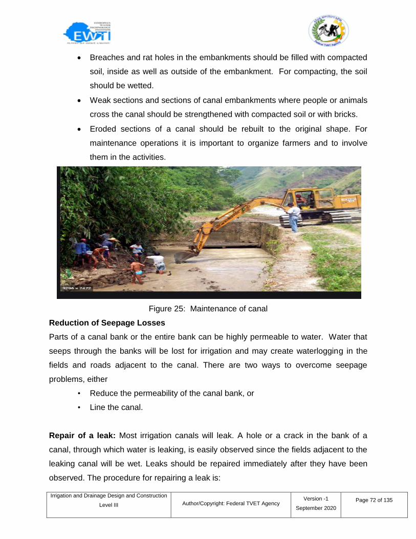
Irrigation and Drainage Design and Construction
Level III
Author/Copyright: Federal TVET Agency Version -1
September 2020
Page 72 of 135
Breaches and rat holes in the embankments should be filled with compacted
soil, inside as well as outside of the embankment. For compacting, the soil
should be wetted.
Weak sections and sections of canal embankments where people or animals
cross the canal should be strengthened with compacted soil or with bricks.
Eroded sections of a canal should be rebuilt to the original shape. For
maintenance operations it is important to organize farmers and to involve
them in the activities.
Figure 25: Maintenance of canal
Reduction of Seepage Losses
Parts of a canal bank or the entire bank can be highly permeable to water. Water that
seeps through the banks will be lost for irrigation and may create waterlogging in the
fields and roads adjacent to the canal. There are two ways to overcome seepage
problems, either
• Reduce the permeability of the canal bank, or
• Line the canal.
Repair of a leak: Most irrigation canals will leak. A hole or a crack in the bank of a
canal, through which water is leaking, is easily observed since the fields adjacent to the
leaking canal will be wet. Leaks should be repaired immediately after they have been
observed. The procedure for repairing a leak is:
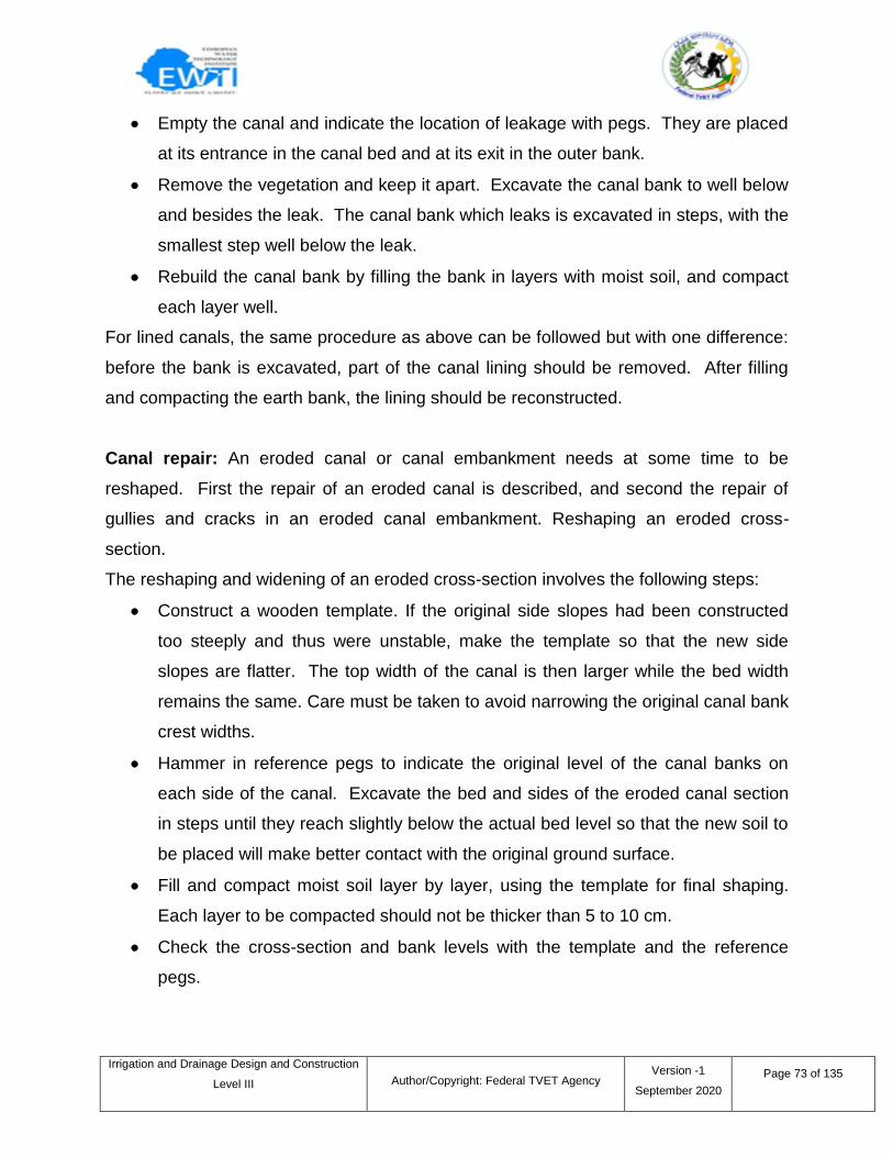
Irrigation and Drainage Design and Construction
Level III
Author/Copyright: Federal TVET Agency Version -1
September 2020
Page 73 of 135
Empty the canal and indicate the location of leakage with pegs. They are placed
at its entrance in the canal bed and at its exit in the outer bank.
Remove the vegetation and keep it apart. Excavate the canal bank to well below
and besides the leak. The canal bank which leaks is excavated in steps, with the
smallest step well below the leak.
Rebuild the canal bank by filling the bank in layers with moist soil, and compact
each layer well.
For lined canals, the same procedure as above can be followed but with one difference:
before the bank is excavated, part of the canal lining should be removed. After filling
and compacting the earth bank, the lining should be reconstructed.
Canal repair: An eroded canal or canal embankment needs at some time to be
reshaped. First the repair of an eroded canal is described, and second the repair of
gullies and cracks in an eroded canal embankment. Reshaping an eroded cross-
section.
The reshaping and widening of an eroded cross-section involves the following steps:
Construct a wooden template. If the original side slopes had been constructed
too steeply and thus were unstable, make the template so that the new side
slopes are flatter. The top width of the canal is then larger while the bed width
remains the same. Care must be taken to avoid narrowing the original canal bank
crest widths.
Hammer in reference pegs to indicate the original level of the canal banks on
each side of the canal. Excavate the bed and sides of the eroded canal section
in steps until they reach slightly below the actual bed level so that the new soil to
be placed will make better contact with the original ground surface.
Fill and compact moist soil layer by layer, using the template for final shaping.
Each layer to be compacted should not be thicker than 5 to 10 cm.
Check the cross-section and bank levels with the template and the reference
pegs.
Irrigation and Drainage Design and Construction
Level III
Author/Copyright: Federal TVET Agency Version -1
September 2020
Page 74 of 135
Repair of cracks and gullies in a canal embankment The repair of cracks and gullies can
be executed as follows:
Remove any plants from banks which show cracking and in which small gullies
have been formed by overtopping water or by heavy rainfall.
In the case of deep cracks and gullies, excavate the bank partly. Small cracks
are to be filled with fine textured soil, moistened and compacted.
Rebuild the bank by filling in layers and compacting the moist soil.
3.6 Causes of drainage failure
Some farmers suffer from drainage problems not because they have no drains, but
because the existing drainage system has collapsed, become blocked, or are otherwise
in need of repair and rehabilitation. Many more will find that the nearest convenient
point of discharge for a new drainage system is an existing primary drainage pipe or
canal that needs attention if it is to function properly.
Collapse and blockage are the principal types of drainage failure. Each of these can
have several causes. Collapse of drains can occur through:
erosion of the bottom and sides of the drain (scouring);
excessive pressure of water in the ground beneath and beside the drain lining
vehicles passing over or too close beside the drains; -root growth, especially
from nearby trees;
crown corrosion in closed drains containing sewage.
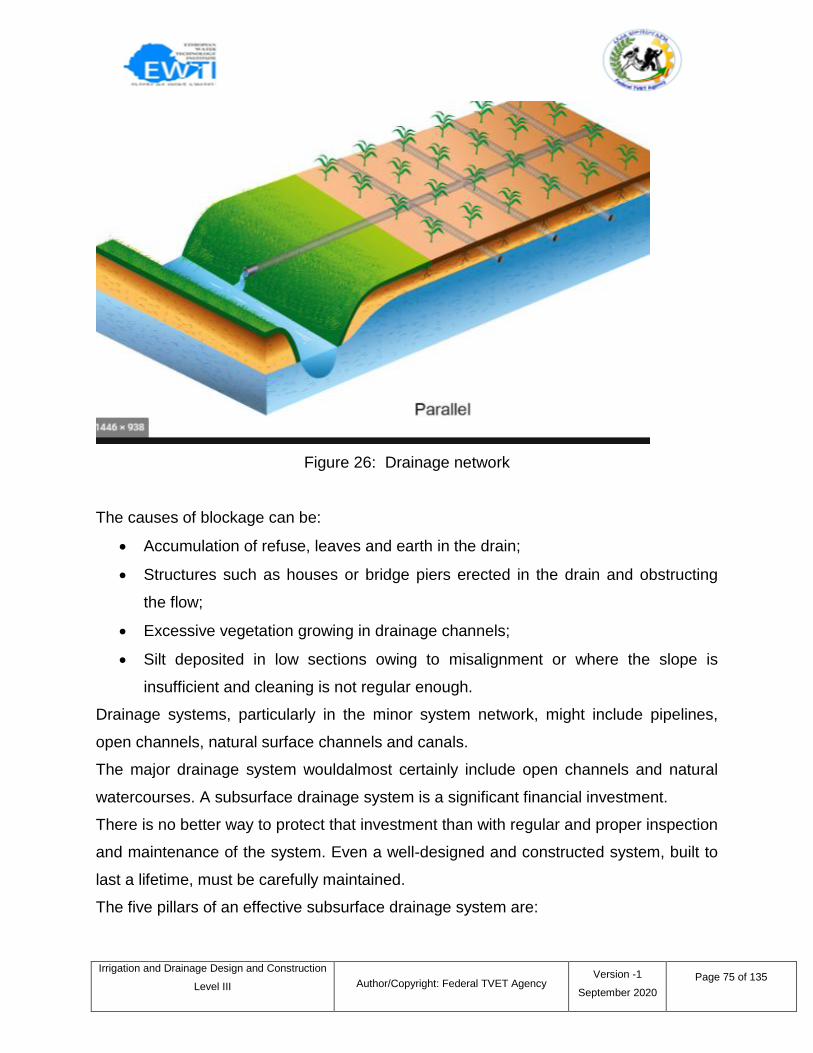
Irrigation and Drainage Design and Construction
Level III
Author/Copyright: Federal TVET Agency Version -1
September 2020
Page 75 of 135
Figure 26: Drainage network
The causes of blockage can be:
Accumulation of refuse, leaves and earth in the drain;
Structures such as houses or bridge piers erected in the drain and obstructing
the flow;
Excessive vegetation growing in drainage channels;
Silt deposited in low sections owing to misalignment or where the slope is
insufficient and cleaning is not regular enough.
Drainage systems, particularly in the minor system network, might include pipelines,
open channels, natural surface channels and canals.
The major drainage system wouldalmost certainly include open channels and natural
watercourses. A subsurface drainage system is a significant financial investment.
There is no better way to protect that investment than with regular and proper inspection
and maintenance of the system. Even a well-designed and constructed system, built to
last a lifetime, must be carefully maintained.
The five pillars of an effective subsurface drainage system are:
Irrigation and Drainage Design and Construction
Level III
Author/Copyright: Federal TVET Agency Version -1
September 2020
Page 76 of 135
Quality material – including pipe, envelope/filter (if necessary), fittings,
risers, etc.
Proper design – completed by a licensed drainage contractor or a
professional engineer
Proper installation – completed by a licensed drainage contractor
Compatible land management practices
Regular inspection and maintenance
3.7 Maintenance of drainage system
Properly designed and constructed drainage systems require minimal maintenance and
repair after the first few years following installation. However, it is important that a new
subsurface drainage system be carefully inspected and maintained for the first two or
three years.
Any weak spots that have developed in the lateral and main drains and any backfilled
areas that have settled can be remedied and filled in. There is some ongoing
maintenance to complete every year but this should be minimal for most systems.
If the drainage system becomes blocked with tree roots:
Reroute the drainage pipe away from the tree.
Remove and replace the section of blocked drains and remove the tree
causing the problem.
Replace the drain using continuous non-perforated pipe for a distance of
15 m on either side of the tree.
Some commercial crops have roots that grow into drain lines and clog them. Roots
from annual crops such as alfalfa, brome grass, rye grass, canola and sugar beets will
usually clear themselves when the crop is harvested.
If a problem is encountered:
Avoid growing the problem crops again.
Flush the roots from the drain pipe using low-pressure jet cleaning.
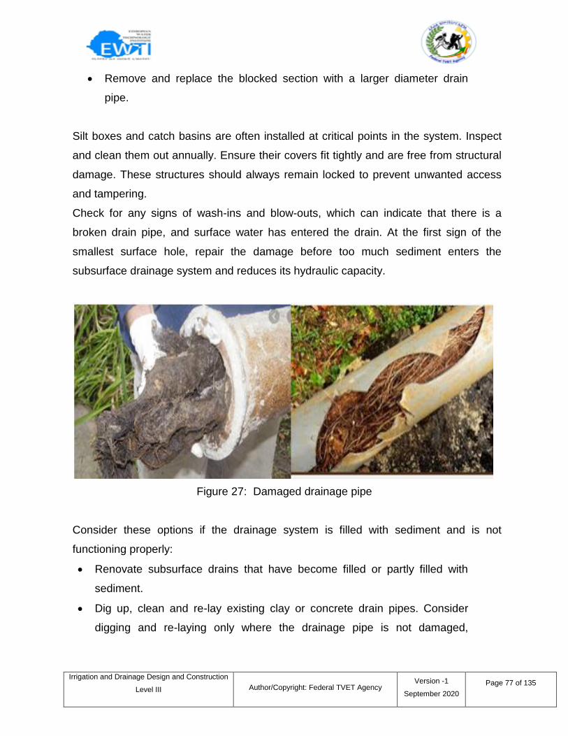
Irrigation and Drainage Design and Construction
Level III
Author/Copyright: Federal TVET Agency Version -1
September 2020
Page 77 of 135
Remove and replace the blocked section with a larger diameter drain
pipe.
Silt boxes and catch basins are often installed at critical points in the system. Inspect
and clean them out annually. Ensure their covers fit tightly and are free from structural
damage. These structures should always remain locked to prevent unwanted access
and tampering.
Check for any signs of wash-ins and blow-outs, which can indicate that there is a
broken drain pipe, and surface water has entered the drain. At the first sign of the
smallest surface hole, repair the damage before too much sediment enters the
subsurface drainage system and reduces its hydraulic capacity.
Figure 27: Damaged drainage pipe
Consider these options if the drainage system is filled with sediment and is not
functioning properly:
Renovate subsurface drains that have become filled or partly filled with
sediment.
Dig up, clean and re-lay existing clay or concrete drain pipes. Consider
digging and re-laying only where the drainage pipe is not damaged,
Irrigation and Drainage Design and Construction
Level III
Author/Copyright: Federal TVET Agency Version -1
September 2020
Page 78 of 135
carelessly laid with joints having wide gaps or not protected with a cover
material to exclude sediment.
Clean lateral drains through the use of sewer-cleaning rods or flushing if
the deposit is only for a short stretch of pipe. Thick deposits over the length
of the pipe are difficult to remove.
Cleaning subsurface drains uses the same procedures as cleaning sanitary sewers.
Holes are dug down to the drain at intervals of 10–25 m, depending upon the size
of the drain and the amount of sediment to be removed. A short section of the
drain is removed to allow a fabricated steel rod with a hook or corkscrew end, or
short-jointed sewer rods, to be inserted into the drain. After the rod has been
pulled through the drain several times, clean the drain further with a ball of barbed
wire or a chain.
Flushing the drain is also recommended. To flush and clean a drain, a reasonable
supply of water must be available. Special drain-flushing equipment is available,
and the success of the procedure depends on the nature of the deposit in the
drain. Use a large volume of water for flushing rather than high pressure. There
may be regulatory concerns with flushing any sediment into the receiving water
body.
Surface Water Inlets: Inspect all surface water inlets twice a year (spring and fall),
and ensure that all of the markers are still in place and clearly visible. Re-mark if
necessary.
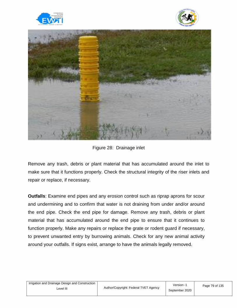
Irrigation and Drainage Design and Construction
Level III
Author/Copyright: Federal TVET Agency Version -1
September 2020
Page 79 of 135
Figure 28: Drainage inlet
Remove any trash, debris or plant material that has accumulated around the inlet to
make sure that it functions properly. Check the structural integrity of the riser inlets and
repair or replace, if necessary.
Outfalls: Examine end pipes and any erosion control such as riprap aprons for scour
and undermining and to confirm that water is not draining from under and/or around
the end pipe. Check the end pipe for damage. Remove any trash, debris or plant
material that has accumulated around the end pipe to ensure that it continues to
function properly. Make any repairs or replace the grate or rodent guard if necessary,
to prevent unwanted entry by burrowing animals. Check for any new animal activity
around your outfalls. If signs exist, arrange to have the animals legally removed.
Irrigation and Drainage Design and Construction
Level III
Author/Copyright: Federal TVET Agency Version -1
September 2020
Page 80 of 135
Self-check 3 Written Test
I. Choose the best answer
1. Which of the following is the common problem of irrigation structures
a. Leakage b. erosion c. Siltation d. rot and rust e. all
2. The reason for leakage and erosion of irrigation structures.
a. Walls may be too thin
b. The concrete mix used in constructions may be too sandy
c. Back-fill may not have been compacted sufficiently
d. All
3. Which of the following is a factor for developing leaks
a. By rat or termite holes in a canal bed or sides.
b. Seepage around structures
c. gates which are not tightly sealed
d. All
4. Which one of the following is not canal maintenance
a. Weeding b. desilting c. re-shaping d. none
5. Activity used to avoid overtopping.
a. Reducing discharge
b. Increasing velocity
c. Increasing water volume
d. all
II. Short Answer Questions
Directions: Answer all the questions listed below. Use the Answer sheet provided in
the next page:
1. List and describe common problems of irrigation structure.
2. List the common problems of the canal networks.
3. Maintenance of structures consists of two main activities.
4. Write solutions for blocked drainage networks.
5. Briefly describe the maintenance activities of irrigation structures
Irrigation and Drainage Design and Construction
Level III
Author/Copyright: Federal TVET Agency Version -1
September 2020
Page 81 of 135
Note: Each question carries 2 points: Satisfactory rating - 18 points:
Unsatisfactory - below 9 points
You can ask your teacher for the copy of the correct answers.
Answer Sheet
Score = ___________
Rating: ___________
Name: _________________________ Date: _______________
Choose the best answer
1..___ 2.._____ 3.._____ 4. ____ 5. ____
Short Answer Questions
1.____________________________________________________________________
2.____________________________________________________________________
3.____________________________________________________________________
4.____________________________________________________________________
5.___________________________________________________________________
Irrigation and Drainage Design and Construction
Level III
Author/Copyright: Federal TVET Agency Version -1
September 2020
Page 82 of 135
4.1 Introduction
Subsurface Drain defines as a conduit such as corrugated plastic tubing, tile, or pipe,
installed beneath the ground surface to collect and/or convey drainage water. This sub
drainage system contains different components like drain mains, laterals,
outlets/outfalls, fittings, and pumps. They are briefly described in the next section.
4.2 Identifying drainage components and fittings
4.2.1 Drain pipes
Drain pipes are large pipes that carries away the discharge of excess irrigation water.
Clay, concrete and plastic pipes give satisfactory results if they meet quality standards
and are properly installed. Collector pipes are made of concrete or plastic. However,
perforated corrugated plastic collectors, wrapped with a sheet envelope, may be
installed comparatively easily if the surrounding soil consists of quicksand or has other
―quick‖ properties.
4.2.2 Lateral drain pipes
Laterals are the smaller diameter pipes used to collect the water from the area to be
drained. These then deliver the drainage water to larger water pipes or main drains.
4.2.3 Outfalls
Outfalls connect the main drain of a subsurface drainage system to an outlet such as a
drainage channel or natural watercourse.
Protect the outfall from erosion, undermining, settlement, ice damage, rodents, silting,
shifting and damage by machinery and livestock. If possible, use a length of continuous
rigid, non-perforated pipe (usually corrugated metal pipe) as an end pipe for the outfall.
Information sheet – 4 Identifying, placing and joining drainage components and
associated fittings
Irrigation and Drainage Design and Construction
Level III
Author/Copyright: Federal TVET Agency Version -1
September 2020
Page 83 of 135
4.3 Selecting components of Drainage
In theory, there are valid considerations to select specific types of drainpipe. In practice,
selection is mostly based on cost comparison and on local availability. In addition, the
following observations may be relevant:
If all types of pipe are available, the use of corrugated plastic pipes has distinct
advantages
If pipes are not locally available, local manufacture of concrete pipes is the most
straightforward and the easiest to implement. It requires less skill than
manufacturing other types of pipe, and is already economical on a small scale.
The manufacturing cost of small diameter pipe (i.e. < 100 mm) is usually of the
same order for clay tiles, concrete tiles and plastic. For large diameter pipes,
however, concrete is usually the cheapest and plastic the most expensive.
4.3.1 Clay tiles
Clay tile may be either porous or glazed. Pipe sections are abutted against each other
and water enters through the joints. Good quality pipes are adequately baked and are
free from cracks and blisters. Standard drainpipe sizes are 50, 65, 75, 80, 100, 130,
160, and 200 mm inside diameter. Current clay tiles have lengths of 300 or 333 mm.
Clay tile is very durable and highly resistant to weathering and deterioration in
aggressive soil conditions e.g. in soils containing sulphates and corrosive chemicals.
Has excellent bearing strength.
4.3.2 Concrete tiles
Concrete pipes are used mostly in medium to large sizes, with inside diameters of 100,
150 and 200 mm and up, and section lengths of 0.60, 0.91, 1.22 and 2.40 m. Tile over
300 mm inside diameter is usually reinforced. Butt joints are common. Pipes should be
well formed, finished, free from cracks and chips, and properly cured.
Pipes made with ordinary cement are liable to deteriorate in acidic and high sulphates
soils, and by water carrying certain alkali salts or other chemicals.
Irrigation and Drainage Design and Construction
Level III
Author/Copyright: Federal TVET Agency Version -1
September 2020
Page 84 of 135
Concrete pipes should not be used at locations where industrial waste or house refuse
has been collected. Special high sulphate-resistant cements and high-density concrete
should be used to resist chemical attack.
4.3.3 Plastic drainpipes
The main advantage of plastic pipes is their low weight per unit length, greatly reducing
transportation cost. An additional cost-saving factor is the reduced need for the labour,
required for installation. Smooth plastic pipes were made of rigid polyvinyl chloride
(PVC).
Corrugated plastic pipes were advantageous, viz.:
• Light weight
• Long, continuous length
• Flexibility for handling, transportation and installation.
• Easy wrapping with envelope materials.
• lower labor cost for manufacture, handling, transportation and installation.
• Inert to all common soil chemicals.
Corrugated pipes also have disadvantages, compared to clay and concrete pipes:
• Vulnerability to deterioration from UV-radiation when exposed to sunlight for long
periods, especially if made of PVC.
• Increased brittleness at low temperatures.
• Increased deflection risk at high temperatures and excessive stretch during
installation.
• Lower deflection resistance under permanent load.
• Risk of collapse under sudden load
• Smaller transport capacity.
• Not fire resistant.
• Not easy to relocate in the field with a tile probe without damaging the pipe.
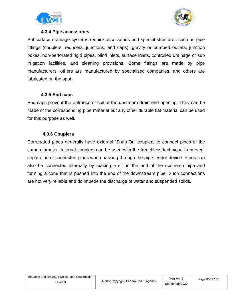
Irrigation and Drainage Design and Construction
Level III
Author/Copyright: Federal TVET Agency Version -1
September 2020
Page 85 of 135
4.3 4 Pipe accessories
Subsurface drainage systems require accessories and special structures such as pipe
fittings (couplers, reducers, junctions, end caps), gravity or pumped outlets, junction
boxes, non-perforated rigid pipes, blind inlets, surface inlets, controlled drainage or sub
irrigation facilities, and cleaning provisions. Some fittings are made by pipe
manufacturers, others are manufactured by specialized companies, and others are
fabricated on the spot.
4.3.5 End caps
End caps prevent the entrance of soil at the upstream drain-end opening. They can be
made of the corresponding pipe material but any other durable flat material can be used
for this purpose as well.
4.3.6 Couplers
Corrugated pipes generally have external ‗Snap-On‘ couplers to connect pipes of the
same diameter. Internal couplers can be used with the trenchless technique to prevent
separation of connected pipes when passing through the pipe feeder device. Pipes can
also be connected internally by making a slit in the end of the upstream pipe and
forming a cone that is pushed into the end of the downstream pipe. Such connections
are not very reliable and do impede the discharge of water and suspended solids.
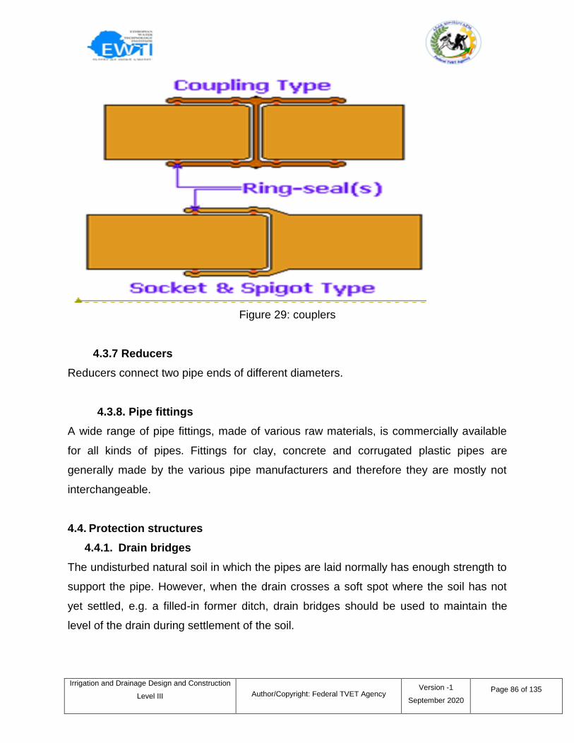
Irrigation and Drainage Design and Construction
Level III
Author/Copyright: Federal TVET Agency Version -1
September 2020
Page 86 of 135
Figure 29: couplers
4.3.7 Reducers
Reducers connect two pipe ends of different diameters.
4.3.8. Pipe fittings
A wide range of pipe fittings, made of various raw materials, is commercially available
for all kinds of pipes. Fittings for clay, concrete and corrugated plastic pipes are
generally made by the various pipe manufacturers and therefore they are mostly not
interchangeable.
4.4. Protection structures
4.4.1. Drain bridges
The undisturbed natural soil in which the pipes are laid normally has enough strength to
support the pipe. However, when the drain crosses a soft spot where the soil has not
yet settled, e.g. a filled-in former ditch, drain bridges should be used to maintain the
level of the drain during settlement of the soil.
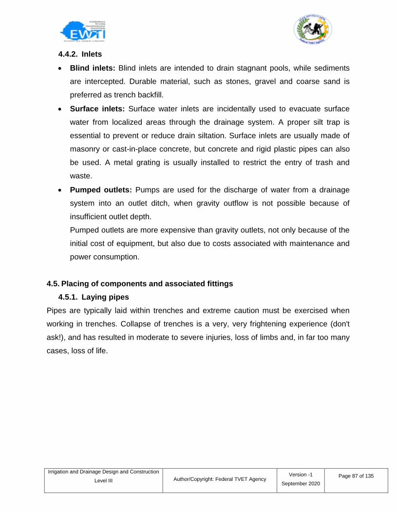
Irrigation and Drainage Design and Construction
Level III
Author/Copyright: Federal TVET Agency Version -1
September 2020
Page 87 of 135
4.4.2. Inlets
Blind inlets: Blind inlets are intended to drain stagnant pools, while sediments
are intercepted. Durable material, such as stones, gravel and coarse sand is
preferred as trench backfill.
Surface inlets: Surface water inlets are incidentally used to evacuate surface
water from localized areas through the drainage system. A proper silt trap is
essential to prevent or reduce drain siltation. Surface inlets are usually made of
masonry or cast-in-place concrete, but concrete and rigid plastic pipes can also
be used. A metal grating is usually installed to restrict the entry of trash and
waste.
Pumped outlets: Pumps are used for the discharge of water from a drainage
system into an outlet ditch, when gravity outflow is not possible because of
insufficient outlet depth.
Pumped outlets are more expensive than gravity outlets, not only because of the
initial cost of equipment, but also due to costs associated with maintenance and
power consumption.
4.5. Placing of components and associated fittings
4.5.1. Laying pipes
Pipes are typically laid within trenches and extreme caution must be exercised when
working in trenches. Collapse of trenches is a very, very frightening experience (don't
ask!), and has resulted in moderate to severe injuries, loss of limbs and, in far too many
cases, loss of life.
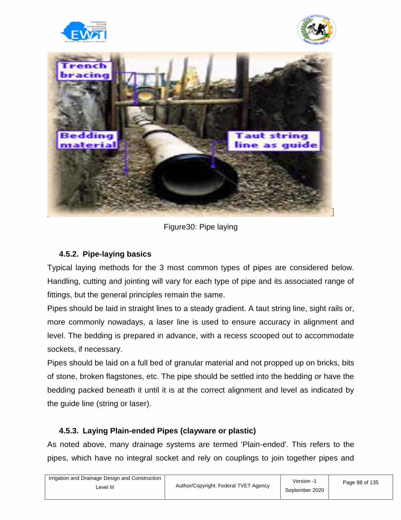
Irrigation and Drainage Design and Construction
Level III
Author/Copyright: Federal TVET Agency Version -1
September 2020
Page 88 of 135
Figure30: Pipe laying
4.5.2. Pipe-laying basics
Typical laying methods for the 3 most common types of pipes are considered below.
Handling, cutting and jointing will vary for each type of pipe and its associated range of
fittings, but the general principles remain the same.
Pipes should be laid in straight lines to a steady gradient. A taut string line, sight rails or,
more commonly nowadays, a laser line is used to ensure accuracy in alignment and
level. The bedding is prepared in advance, with a recess scooped out to accommodate
sockets, if necessary.
Pipes should be laid on a full bed of granular material and not propped up on bricks, bits
of stone, broken flagstones, etc. The pipe should be settled into the bedding or have the
bedding packed beneath it until it is at the correct alignment and level as indicated by
the guide line (string or laser).
4.5.3. Laying Plain-ended Pipes (clayware or plastic)
As noted above, many drainage systems are termed 'Plain-ended'. This refers to the
pipes, which have no integral socket and rely on couplings to join together pipes and
Irrigation and Drainage Design and Construction
Level III
Author/Copyright: Federal TVET Agency Version -1
September 2020
Page 89 of 135
fittings. This type of system has some advantages over socket and spigot types, in that
the separate couplings offer greater flexibility and off-cuts from pipes can utilized by
simply adding a coupling to each end.
The ends of the pipes, whether they are plastic ware or clayware, are chamfered when
new. Pipes and fittings that have been cut may need to have the cut end chamfered on-
site; cut ends to plastic ware can be easily chamfered by means of a file, whereas
clayware requires skilled use of a light hammer to 'fettle' the cut end, or the use of a
special pipe-trimming tool.
lubricate end of pipe/fitting and coupling*
slide coupling onto pipe/fitting
lubricate receiving end of coupling and end of next pipe/fitting
slide next pipe/fitting into coupling
repeat as required
Plastic ware drainage is available with 2 types of jointing:
Ring-seal
Solvent-weld
Ring-seal jointing may be found as separate couplings or the pipes and fittings might
have in-built couplings with identifiable 'female' and 'male' ends, known as sockets (f)
and spigots (m). The spigot or coupling is lubricated and the pipes brought together with
gentle force.
Solvent-weld systems rely on the pipes, couplings and fittings being 'glued' together by
means of a special solvent. Individual manufacturers provide jointing instructions, and
the correct solvents/adhesives for their individual ranges. Again, there may be separate
or in-built couplings, depending on the particular system chosen.
It is essential that the manufacturers' jointing instructions are followed to the letter, and
that solvent cements are not mixed between different products/manufacturers.
Irrigation and Drainage Design and Construction
Level III
Author/Copyright: Federal TVET Agency Version -1
September 2020
Page 90 of 135
4.5.4. Laying Socketed Clayware
Plastic ware is simply cut to size using a handsaw, full-size hacksaw or angle grinder,
and then using a file to chamfer the newly-cut end.
Clayware (along with other harder materials) requires special cutting tools. The two
most common methods are to use either a power cut-off saw or a pipe-cutting tool,
which wraps around the pipe, placing a series of hardened-steel discs in direct contact
with the barrel of the pipe, and then relies on pressure being exerted via the lever-
handles to 'snap' the pipe at the required point.
4.5.5. Fittings and Access Points
There is a huge range of fittings available for all types of drainage systems. These
include gullies, hoppers, traps, bends, and junctions as standard items, as well as
access chambers, rodding eyes and inspection chambers which are designed to grant
access for inspection and/or maintenance. Manholes tend to be larger chambers (at
least 600mm width), with half-pipes known as 'channels' set into the base (see other
drainage pages).
Irrigation and Drainage Design and Construction
Level III
Author/Copyright: Federal TVET Agency Version -1
September 2020
Page 91 of 135
Self-check 4 Written Test
Short Answer Questions
Directions: Answer all the questions listed below. Use the Answer sheet provided in
the next page:
1. List components of sub-surface drainage system.
2. List drainage system fittings.
3. Briefly describe types of plastic ware jointing.
4. what is the difference of pumped outlet from gravity?
Note: Each question carries 5 points: Satisfactory rating - 20 points:
Unsatisfactory - below 10 points
You can ask your teacher for the copy of the correct answers.
Answer Sheet
Score = ___________
Rating: ___________
Name: _________________________ Date: _______________
Short Answer Questions
1. ________________________________________________________________
2. ________________________________________________________________
3. ________________________________________________________________
4. ________________________________________________________________
Irrigation and Drainage Design and Construction
Level III
Author/Copyright: Federal TVET Agency Version -1
September 2020
Page 92 of 135
5.1 Introduction
Irrigation system maintenance on golf course involves four major efforts: calibration and
auditing, preventive maintenance, corrective maintenance, and record keeping. Good
system management starts with good preventive maintenance procedures and
recordkeeping.
5.2 Preventive maintenance
Preventative maintenance Preventative maintenance is work that, if carried out, will
result in preventing more expensive maintenance or repair work at a later date. A
classic example of preventative maintenance is the prevention of seepage around or
under hydraulic structures; if seepage is identified and remedial action taken in good
time, the collapse of the structure can be prevented, saving considerable expense.
Priority areas for preventative maintenance include:
Checking for seepage around or under structures, especially if there is a high-
pressure head across the structure;
Grading of embankments and canal/ drain inspection/access roads to avoid
ponding of water and gulling;
Closing river intake gates before high flood levels in the river, both to avoid
excessive discharges in the canal and
Intake of water with high sediment loads;
Painting of metal and wood components, particularly gates and gate frames
5.2.1 Reducing the permeability of a canal bank
The permeability of a canal bank can be reduced by compacting the center, or core of
the embankment. The core is first excavated by digging a narrow trench, and then
replaced with soil in layers, compacting each layer. The compacted core should extend
above the water level. The procedure is:
Remove the vegetation on the canal bank and the top of the bank.
Information sheet – 5 Performing preventative maintenance program
Irrigation and Drainage Design and Construction
Level III
Author/Copyright: Federal TVET Agency Version -1
September 2020
Page 93 of 135
Excavate a narrow trench near the inner side of the canal bank. A trench is
excavated in the permeable section of the canal. The width of the trench is at
least 0.5 x the water depth in the canal. The bottom of the trench should be
some 20 cm below the original ground surface elevation
Compact the bottom of the trench with a manual tamper and replace the soil in
layers of about 5 to 10 cm each. The soil should be moist when being
compacted. When the excavated material is rather sandy, the core should be
filled with other material which contains more clay. Each layer is wetted and the
wetted soil is then compacted. Wetting the soil is conditional for good
compaction, since the aggregates in soil that is moist will disintegrate by tamping,
while those in dry soil will not.
Fill and compact the trench until the top is reached.
5.2.2 How to avoid Overtopping
Overtopping of a canal section is caused by an excessive discharge in that section in
relation to the actual canal capacity. Canal banks which are frequently overtopped are
very probably eroded and lowered, and thus the actual capacity will be less than the
original capacity for which the canal has been designed.
Overtopping can be avoided in two ways, either:
Reduce the discharge, or
Increase the canal capacity.
No explanation is necessary for the first solution, and so only the second solution, which
reestablishes the canal capacity, is described below.
The procedure to re-establish a canal capacity by rebuilding its banks is:
Remove the vegetation, if any. Hammer pegs in the canal bank at both sides of
the section concerned. (With these pegs and a rope the level of the section can
be checked).
Excavate the top and sides of the bank like stairs.
Irrigation and Drainage Design and Construction
Level III
Author/Copyright: Federal TVET Agency Version -1
September 2020
Page 94 of 135
Rebuild the bank by filling the excavated portion with clayey soil. Fill by layers of
5 to 10 cm and compact it in wet condition. While raising the embankment, check
the level regularly.
Trim the sides and lay grass sods on the bank when the top is reached.
When it is impossible to avoid high water levels, an emergency outlet, or spillway, can
be installed. An emergency outlet consists of a protected lowered section of a canal
embankment and a protected outlet to the drainage system. Such a structure will allow
water to escape into the drainage system without damaging the canal banks.
5.2.3 Preventing erosion
Erosion of an irrigation canal may be prevented by either:
Reducing the flow velocity, or
Lining the canal.
Reducing the flow velocity,the flow velocity in a canal can be reduced by reducing the
canal bed slope. To avoid such an excessive canal bed slope in the steep area, the
slope of the canal can be modified by constructing part of the canal in cut and part in fill,
which however involves moving large volumes of earth. The volume of earth movement
in cut and fill can be reduced by installing drop structures, which connect two sections of
a canal with different elevations. In order to have the same canal capacity, the canal
cross-section has to be made bigger. Of course, it is not easy to rebuild an existing
canal in order to modify its bed slope.
Irrigation and Drainage Design and Construction
Level III
Author/Copyright: Federal TVET Agency Version -1
September 2020
Page 95 of 135
Self-Check 5 Test
Directions: Choose the best answer for the following questions. Use the Answer sheet
provided:
1. ___ will result in preventing more expensive repair work at a later date.
a. Corrective maintenance
b. preventive maintenance
c. reactive maintenance
d. All
2. Which of the following is priority areas for preventative maintenance?
a. Checking for seepage
b. Grading of embankment
c. Painting of metal and wood components
d. All
3. ____of a canal section is caused by an excessive discharge in that section in
relation to the actual canal capacity.
a. Overtopping b. flooding c. erosion d. siltation.
4. Which of the following is a measure used to reduce erosion of canals?
a. Lining b. Reducing flow velocity c. a & b d. none
5. Overtopping can be avoided by___.
a. Reduce the discharge
b. Increase the canal capacity
c. Reduce velocity
d. All except c
Answer Sheet
Score = ___________
Rating: ___________
Name: _________________________ Date: _______________
Short Answer Questions
1. ___ 4. ______
2. ___ 5. ______
3. __
Note: Satisfactory rating - 5 points Unsatisfactory - below 5 points
You can ask you teacher for the copy of the correct answers.
Irrigation and Drainage Design and Construction
Level III
Author/Copyright: Federal TVET Agency Version -1
September 2020
Page 96 of 135
Tools and Equipments
Shovel, hoe, spade, Rake, pick axe, meter
Selected soil.
Wood, peg
Compacting power tool
Procedures
1. Construct a wooden template
2. Select the feasible diversion type based on the site condition.
3. Hammer in reference pegs to indicate the original level of the canal banks on
each side of the canal.
4. Fill and compact moist soil layer by layer, using the template for final shaping.
5. Check the cross-section and bank levels with the template and the reference
pegs.
Tools and Equipments
Shovel, hoe, spade, Rake, pick axe, meter
cement
Wood, peg
Compacting power tool
Procedures
1. Empty the canal and indicate the location of leakage with pegs
2. Select the feasible diversion type based on the site condition.
3. Remove the vegetation and keep it apart. Excavate the canal bank to well below
and besides the leak.
Operation Sheet 1 Correcting system faults
Operation Sheet 2 Repair of a leak from lined canal
Irrigation and Drainage Design and Construction
Level III
Author/Copyright: Federal TVET Agency Version -1
September 2020
Page 97 of 135
4. Rebuild the canal bank by filling the bank in layers with moist soil, and compact
each layer well.
5. Part of the canal lining should be removed. After filling and compacting the earth
bank, the lining should be reconstructed.
Tools and Equipments
Shovel, hoe, spade, Rake, pick axe, meter
Drain pipe
Procedures
Reroute the drainage pipe away from the tree.
Dig up, remove and replace the section of blocked drains and remove
the tree causing the problem.
Replace the drain using continuous non-perforated pipe for a distance
of 15 m on either side of the tree.
Tools Required
1. Chisel point bar
2. Cordless drill
3. Garden rake
4. Hammer
5. Level
6. Line level
7. Spade
8. Tape measure
9. Utility knife
Operation Sheet 3 Repair of drainage line blocked with tree root
Operation Sheet 4 Identifying, placing and joining drainage components
and associated fittings
Irrigation and Drainage Design and Construction
Level III
Author/Copyright: Federal TVET Agency Version -1
September 2020
Page 98 of 135
10. Wheelbarrow
Materials Required
1. Crushed rock
2. Drain cover
3. Drain tubing
4. Dry well
5. Fabric sock
6. Landscape fabric
7. Stakes
8. Y-fittings
Procedures
1. Dig an adjoining trench
2. Connect the drain tube
3. Cover the tube with fabric
4. Make sure the tube slopes to drain the water
5. Attach a cover over the end of the tube
6. Dealing with Backfill.
Irrigation and Drainage Design and Construction
Level III
Author/Copyright: Federal TVET Agency Version -1
September 2020
Page 99 of 135
LAP Test Practical Demonstration
Name: _______________________________ Date: ______________
Time started: _________________________ Time finished _______________
Instructions: Given the necessary materials you are required to perform the following
tasks within 4 hours.
1. Identifying, placing and joining drainage components and associated
fittings (1hr)
2. Conduct correcting system faults (1 hour).
3. Conduct repair of leak in the lined canal (1 hour).
4. Conduct repair of blocked drainage line (1 hour).
Irrigation and Drainage Design and Construction
Level III
Author/Copyright: Federal TVET Agency Version -1
September 2020
Page 100 of 135
This learning guide is developed to provide you the necessary information regarding the
following content coverage and topics:
Backfilling, compacting and restoring work site
Checking Repaired or replaced components and earthworks
This guide will also assist you to attain the learning outcome stated in the previous
page. Specifically, upon completion of this Learning Guide, you will be able to –
Backfill, compact and restore work site
Check Repaired or replaced components and earthworks
Learning Instructions:
1. Read the specific objectives of this Learning Guide.
2. Follow the instructions described below 3 to 6.
3. Read the information written in the information ―Sheet 1and Sheet 2‖in page 101
and 107 respectively.
4. Accomplish the ―Self-check 1 and Self- check 2‖ -‖ in page 106 and 108
respectively
5. If you earned a satisfactory evaluation from the ―Self-check‖ proceed to ―Operation
Sheet 1 in page 109
6. Do the ―LAP test‖ in page 110
Instruction Sheet Learning Guide – 58: Check work and restore work site
Irrigation and Drainage Design and Construction
Level III
Author/Copyright: Federal TVET Agency Version -1
September 2020
Page 101 of 135
1.1 Introduction
Most areas require that the soil surface and vegetation be restored to a pre-construction
condition. This may necessitate removal and stockpiling of topsoil and temporary
preservation of particular vegetation until post-construction revegetating is
accomplished. Revegetating and promoting vegetation should be based on local
conditions and requirements. If a project traverses hills or steep terrain, erosion control
devices may be required in combination with revegetation efforts.
1.2 Backfilling
Backfilling is the process of reusing or replacing the soil that is removed during the
excavation of trenches, foundation, and ground bearing slabs or other groundwork to
support and strengthen a structure. Backfill can be made up of the same soil that was
removed during excavation, or can be a mixture of imported soil, rocks and stones
depending on the structural requirements. The need for backfilling will be established
during ground investigations which will also be used by the engineers to formulate a
design. Backfill is quantified in m3.
Excess soil might be taken away from site or set aside for use in other parts of the
project at a later stage. When excavated material is set aside for later use it should be
protected from the elements.
1.3 Compaction
Place and compact filling in uniform layers of thickness appropriate to the nature of
material and the compaction equipment being used. Layers shall extend for the full
width of embankments and shall be placed such that they are parallel to the finished
surface. In earth fills the maximum layer thickness generally shall be 150mm
compacted.
However, greater thicknesses will be permitted subject to the ability of compaction
equipment to achieve specified densities. No layer shall be less than 100mm thick
Information sheet - 1 Backfilling, compacting and restoring work site
Irrigation and Drainage Design and Construction
Level III
Author/Copyright: Federal TVET Agency Version -1
September 2020
Page 102 of 135
compacted. Where area is to be planted or grassed, the top 500mm is to be compacted
to a level not exceeding 85% of the modified maximum dry density.
Reduce layer thicknesses as necessary to ensure the achievement of specified
densities.
1.4 Reinstatement/site stabilization
During and after works there are likely to be areas of disturbance and exposed soils.
These disturbed areas pose an environmental risk, the most common risk being the
discharge of sediment. Sediment (e.g. clay, dirt and sand) is natural substance.
However, it can have significant adverse effects on aquatic environments. Increased
amounts of sediment in waterways can:
Clog the gills of fish and damage other sensitive tissues through abrasion.
Suffocate aquatic plants, fish and insects by smothering them.
Reduce the amount of light entering the water, which can stop plants and
algae growing – removing a major food source for fish and insects.
Increase the risk of flooding. No project is complete until the site/works area is
fully stabilized.
Environmental practices and controls
Stage works to minimize the amount of disturbed area on site.
Put in place diversions (e.g. bunding, sandbags etc.) at stages uphill of the
site to divert clean storm water around the works. This will help to reduce the
amount of contaminated water that you have to manage.
Install storm water catch pit protection measures as a form of secondary
control on downstream receiving catchpoints.
1.5 Common site stabilization/reinstatement practices
1.5.1. Top soiling
Top soiling involves the placement of topsoil over a prepared area. Top soiling is not an
effective stabilization/ reinstatement practice by itself, and forms part of other
techniques by providing a medium for vegetative growth. Top soiling however provides
some limited short-term stabilization by protecting sub‑soils and absorbing water.
Irrigation and Drainage Design and Construction
Level III
Author/Copyright: Federal TVET Agency Version -1
September 2020
Page 103 of 135
Top soiling should be used:
Before top soiling make sure that storm water protection measures, as a form
of secondary control, are in place and remain until the site is stabilized
On relatively flat sites
With mulching techniques until vegetation establishes.
Revegetation techniques:
Grass The planting and establishment of grass is a quick growing option to
stabilize a site. Key things to do when grassing:
Before grassing make sure that storm water protection measures, as a form of
secondary control, are in place and remain until the site is stabilized.
Topsoil if required to provide a good seed bed and ensure quick successful
establishment of grass and vegetation.
Apply seed at the recommended application rate.
Apply mulch to stabilize the area and to help with moisture retention.
Maintain seeded area to assist with germination and ensure a stabilized site.
General planting: Planting is a reinstatement practice that is typically used when
existing vegetation has been removed as part of site works. Planting can protect against
erosion and provides shade to reduce the regrowth of weeds. However, trees and
shrubs take a significant amount of time to produce enough root growth to stabilize a
site. When planting:
Plant during the planting season (March to August).
Improve establishment of planting and reduce maintenance costs by the use of
weed fabrics prior to planting.
Mulch deeply around the plantings as it will help suppress weed growth and help
stabilize the area.
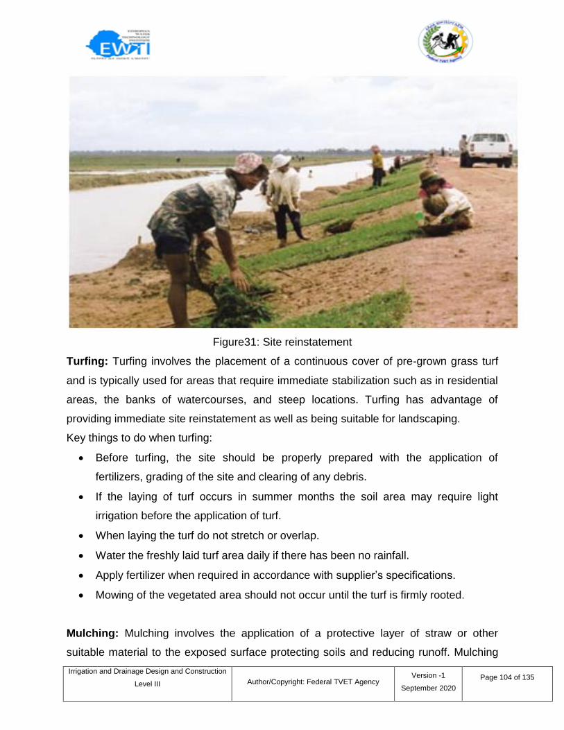
Irrigation and Drainage Design and Construction
Level III
Author/Copyright: Federal TVET Agency Version -1
September 2020
Page 104 of 135
Figure31: Site reinstatement
Turfing: Turfing involves the placement of a continuous cover of pre‑grown grass turf
and is typically used for areas that require immediate stabilization such as in residential
areas, the banks of watercourses, and steep locations. Turfing has advantage of
providing immediate site reinstatement as well as being suitable for landscaping.
Key things to do when turfing:
Before turfing, the site should be properly prepared with the application of
fertilizers, grading of the site and clearing of any debris.
If the laying of turf occurs in summer months the soil area may require light
irrigation before the application of turf.
When laying the turf do not stretch or overlap.
Water the freshly laid turf area daily if there has been no rainfall.
Apply fertilizer when required in accordance with supplier‘s specifications.
Mowing of the vegetated area should not occur until the turf is firmly rooted.
Mulching: Mulching involves the application of a protective layer of straw or other
suitable material to the exposed surface protecting soils and reducing runoff. Mulching
Irrigation and Drainage Design and Construction
Level III
Author/Copyright: Federal TVET Agency Version -1
September 2020
Page 105 of 135
also helps to maintain moisture and promote establishment of desirable vegetation. Key
things to do when mulching:
Before mulching make sure that storm water protection measures, as a form of
secondary control, are in place and remain until the site is stabilized.
Application of mulch should be at an appropriate rate that provides good coverage
of all exposed soil.
The application of mulch should be uniform and will typically be done by hand.
Ensure mulch is compacted to prevent it becoming dislodged during rainfall.
For the best results, total surface coverage must be maintained. Mulch may need
to be reapplied as is settles or breaks down.
1.6 Monitoring and maintenance
It is important that during and after works you:
Check the condition of the stabilization practice on a regular basis particularly
after rainfall.
Ensure that construction equipment does not disturb the reinstated area. This can
be done by erecting a temporary barrier fence to restrict movement of equipment.
Regularly inspect and clean out sediment controls and secondary catch pit
protection.
Once the site is fully stabilized remove environmental controls. Inspect storm water
catchpoints and remove any contamination associated with site works.
Irrigation and Drainage Design and Construction
Level III
Author/Copyright: Federal TVET Agency Version -1
September 2020
Page 106 of 135
Self-check 1 Written Test
Short Answer Questions
Directions: Answer all the questions listed below. Use the Answer sheet provided in
the next page:
1. Define backfilling, compaction and site reinstatement.
2. Briefly describe common site stabilization practices.
Note: Each question carries 10 points: Satisfactory rating - 20 points:
Unsatisfactory - below 10 points
You can ask your teacher for the copy of the correct answers.
Answer Sheet
Score = ___________
Rating: ___________
Name: _________________________ Date: _______________
Short Answer Questions
1.____________________________________________________________________
2.____________________________________________________________________
Irrigation and Drainage Design and Construction
Level III
Author/Copyright: Federal TVET Agency Version -1
September 2020
Page 107 of 135
1.1 Introduction
Checking repaired or replaced components is the part of quality management that
ensures products and services comply with requirements. It is a work method that
facilitates the measurement of the quality characteristics of a unit, compares them with
the established standards, and analyses the differences between the results obtained
and the desired results in order to make decisions which will correct any
differences.Technical specifications define the type of controls that must be carried out
to ensure the construction works are carried out correctly. They include not only
products and materials, but also the execution and completion of the works.
One way of controlling quality is based on the inspection or verification of finished
products. This reception control is usually carried out by people who were not involved
in the production activities, which means that costs can be high, and preventative
activities and improvement plans may not be effective.
It is a final control, located between producer and client, and although it has the
advantage of being impartial, it has a large number of drawbacks, such as slow
information flows, and that the inspectors are not familiar with the circumstances of
production and are not responsible for the production quality. The plan must be drafted
by the contractor before the start of the construction works and will be reviewed
throughout its execution.
The control activities (verification of compliance with specifications, validation of specific
processes, monitoring of activities, inspections and tests), which the units, materials or
services undergo must also be established. These activities can be defined through
inspection, testing plans, action plans and where applicable specific tests (for example,
load tests for structures).
Information sheet – 2 Checking Repaired or replaced components and earthworks
Irrigation and Drainage Design and Construction
Level III
Author/Copyright: Federal TVET Agency Version -1
September 2020
Page 108 of 135
Self-check 2 Written Test
Short Answer Questions
Directions: Answer all the questions listed below. Use the Answer sheet provided in
the next page:
1. What is the benefit of checking repaired components of irrigation and
drainage system?
2. List the activities carried for checking repaired components.
Note: Each question carries 5 points: Satisfactory rating - 10 points:
Unsatisfactory - below 5 points
You can ask your teacher for the copy of the correct answers.
Answer Sheet
Score = ___________
Rating: ___________
Name: _________________________ Date: _______________
Short Answer Questions
1. __________________________________________________________________
2.____________________________________________________________________
Irrigation and Drainage Design and Construction
Level III
Author/Copyright: Federal TVET Agency Version -1
September 2020
Page 109 of 135
Tools and materials
Shovel, hoe, spade, Rake, pick axe, meter
Grass, soil, mulch
Procedures
1. Design landscape.
2. Soiling.
3. Planting/revegetation
4. Mulching.
5. Monitoring and maintenance
Operation Sheet 1 Backfilling, compacting and restoring work site
Irrigation and Drainage Design and Construction
Level III
Author/Copyright: Federal TVET Agency Version -1
September 2020
Page 110 of 135
LAP Test 1 Practical Demonstration
Name: _______________________________ Date: ______________
Time started: _________________________ Time finished _______________
Instructions: Given the necessary materials you are required to perform the following
tasks within 1:3 hour.
1. Backfilling, compacting and restoring work site (1:30 hour).
Irrigation and Drainage Design and Construction
Level III
Author/Copyright: Federal TVET Agency Version -1
September 2020
Page 111 of 135
This learning guide is developed to provide you the necessary information regarding the
following content coverage and topics:
Checking and storing Equipment, tools and materials
Completing Workplace records and process
This guide will also assist you to attain the learning outcome stated in the previous
page. Specifically, upon completion of this Learning Guide, you will be able to –
Check and store equipment, tools and materials
Complete workplace records and process.
Learning Instructions:
1. Read the specific objectives of this Learning Guide.
2. Follow the instructions described below 3 to 4.
3. Read the information written in the information ―Sheet 1, Sheet 2, Sheet 3 and
Sheet 4‖inpage 112 and 120 respectively.
4. Accomplish the ―Self-check 1, Self-check 2, Self-check 3 and Self- check 4‖ -‖ in
page 118 and 128 respectively
5. If you accomplish the self-checks, do operation sheet in page 41 and 42
6. LAP Test in page 43
Instruction Sheet Learning Guide - 59: Finalize Work
Irrigation and Drainage Design and Construction
Level III
Author/Copyright: Federal TVET Agency Version -1
September 2020
Page 112 of 135
1.1 Introduction
Site storage involves the provision of adequate space, protection and control for
materials, components and equipment that are to be kept on a construction site during
the building process.
There are several factors to be considered when deciding on the amount and nature of
storage required.
Physical properties: The size, shape, weight and mode of delivery.
Organization: The planning process to ensure unloading is available and storage
space has been allocated.
Control: Processes for checking the quality and quantity of materials on delivery,
and monitoring stock holdings.
Protection: The necessary protection for durable and non-durable materials and
components from damage.
Security: Guarding against theft and vandalism.
Costs: Costs associated with handling, transporting and stacking requirements,
the workforce required, heating and/or lighting that may be required, facilities to
be provided for subcontractors, and so on.
Processing: What needs to be done to materials before they can be used. Is
there packaging that needs to be removed or returned?
Programme: When are items required, what is the risk to the project of them not
being available, how long in advance are they ordered and how long they will be
on site.
Ownership: Who is legally responsible for items, who will be using them and who
owns them? See Materials on site for more information.
Information sheet - 1 Checking and storing Equipment, tools and materials
Irrigation and Drainage Design and Construction
Level III
Author/Copyright: Federal TVET Agency Version -1
September 2020
Page 113 of 135
Site allocation: Failure to adequately plan for storage space can result in congestion,
or having more materials on site than storage space allows for. The most appropriate
position on site in terms of handling, storage and convenience should be determined.
Unloading deliveries should take place in a clearly marked designated area, away from
other site operations, supervised by a competent person. The distance between storage
areas and the area materials are to be used should be reduced as much as possible to
keep the time and cost required to transport them from place to place at a minimum.
Alternatively, storage areas could be positioned within the reach of a tower crane which
can then be used to move materials as required.
Theft: Materials and equipment may need protection from theft and vandalism,
particularly when left out in the open where they have the potential to be removed late
at night by opportunistic thieves. Close boarded fences are often used which are similar
to hoarding, or chain link fencing with precast concrete posts, sometimes incorporating
a 45° crank which faces out.
Health and safety: There are certain health and safety issues to consider when storing
items on site. Items which are stacked must be stable to ensure they will not fall onto
workers. Workers should not climb or walk on top of materials which are stacked as
they could shift and cause them to fall.
Stored items should not block or obstruct escape routes.
The type of material being stored also needs to be taken into account. If it is hazardous,
it may require specific precautions and control measures such as bunds for toxic
substances or it may need to be kept separate from other substances to prevent a
reaction.
To reduce the risk of an accident, special containers are required to store hazardous
chemicals and dangerous goods. These types of containers may have special
provisions for things like natural ventilation, special compartments, electrical earthing,
and warning signs.
Irrigation and Drainage Design and Construction
Level III
Author/Copyright: Federal TVET Agency Version -1
September 2020
Page 114 of 135
Materials storage: Different types of material will have different storage requirements,
in particular depending on whether they are durable or non-durable.
Drainage pipes: These are usually supplied loose or strapped together on timber
pallets. They should be stacked horizontally with ends reversed in alternate rows. A
driven-in timber stack or column of loose bricks can be used to form end restraints.
Timber: Timber and other joinery items should be stored horizontally and covered in a
scaffold rack, although provision should be made for free air flow, usually by the rack
having open ends and sides, while having a top that is covered. It is advisable for
different timber sizes to be kept separate.
Cement: Since any contact with direct or airborne moisture can cause cement to set, it
must be kept dry. Small quantities of bagged cement should be stacked to a height no
more than 1 m, on a raised dry platform such as a timber pallet.
Medium quantities of bagged cement may need to be stored in a watertight and
fireproof shed, with galvanized steel sides and adjustable legs on bearing plates. Large
quantities of loose cement should be stored in a cement storage silo
Aggregates: It is essential for different aggregate types and sizes to be kept separate.
They should be stored on a clean, hard, free-draining surface, surrounded by retaining
and separating walls of bulk timbers. Stored aggregates should be regularly monitored
for moisture content.
1.2 Tool and Equipment Maintenance
All tools, equipment, and vehicles must be properly maintained so that workers are not
endangered. Construction regulations require inspections of vehicles, tools, machines,
and equipment before use.
Irrigation and Drainage Design and Construction
Level III
Author/Copyright: Federal TVET Agency Version -1
September 2020
Page 115 of 135
Preventive maintenance is the systematic care and protection of tools, equipment,
machines, and vehicles in order to keep them in a safe, usable condition, that limits
downtime and extends productivity. We must always be aware that maintenance tasks
themselves are potentially hazardous and can result in injury. The successful
maintenance program is:
Well organized and scheduled
Controls hazards
Defines operational procedures
Trains key personnel.
Most manufacturers can provide maintenance schedules for their equipment. Large
companies with a fleet of vehicles/equipment typically have a comprehensive
maintenance program due to the capital investment and/or leasing agreements.
Smaller companies may lease equipment and maintenance services may be included in
the leasing agreement.
General requirements for equipment maintenance include:
Obtaining a copy of the maintenance schedule recommended by the
manufacturer.
Ensuring that maintenance is performed as required.
Ensuring that the person(s) performing the maintenance are competent (e.g.
licensed mechanic).
Retaining records of maintenance/service conducted.
Specifying who is responsible for overseeing equipment maintenance and where
the records are kept.
Setting up a system for removal and tagging of damaged or defective tools and
equipment.
Basic Tool Maintenance: Being in the construction industry, our tools and equipment
are the livelihood of our business. Regular maintenance will increase the service life
Irrigation and Drainage Design and Construction
Level III
Author/Copyright: Federal TVET Agency Version -1
September 2020
Page 116 of 135
and performance of your equipment. Take good care of your tools and they will last a
lifetime! Store them well, keep them clean and well-maintained, and you won't regret it.
Clean your tools: After a long day's work, cleaning might be the last thing on your mind
but remember, your tools have been hard at work and will be covered with dirt and
grime. Take a few seconds before packing up to give them a quick wipe down.
Cleaning your tools doesn't have to be difficult at all if you're prepared:
Hand/Garden tools: Most hand tools can be cleaned simply by wiping them
down with a rag. If you find that they are in need of more than just a wipe down,
give them a good wash with soap and water. On the handles, linseed oil on a
damp rag will do the trick
Power tools: As always, safety first so make sure the tool is unplugged before
any cleaning. If you have an air compressor, it will prove useful in helping you
get the dust off it, otherwise, wipe it down and lubricate any moving parts. Be
sure to check the manufacturers manual for any cleaning instructions Whilst
toolboxes don't need to be cleaned on a daily basis, make sure you clean them
out every once in a while. Set aside some time once a month, empty out our
tools and wipe them out.
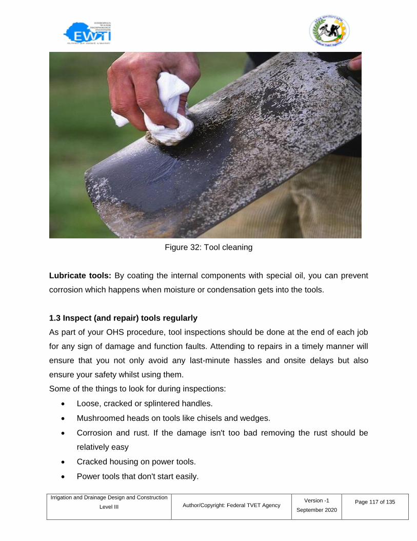
Irrigation and Drainage Design and Construction
Level III
Author/Copyright: Federal TVET Agency Version -1
September 2020
Page 117 of 135
Figure 32: Tool cleaning
Lubricate tools: By coating the internal components with special oil, you can prevent
corrosion which happens when moisture or condensation gets into the tools.
1.3 Inspect (and repair) tools regularly
As part of your OHS procedure, tool inspections should be done at the end of each job
for any sign of damage and function faults. Attending to repairs in a timely manner will
ensure that you not only avoid any last-minute hassles and onsite delays but also
ensure your safety whilst using them.
Some of the things to look for during inspections:
Loose, cracked or splintered handles.
Mushroomed heads on tools like chisels and wedges.
Corrosion and rust. If the damage isn't too bad removing the rust should be
relatively easy
Cracked housing on power tools.
Power tools that don't start easily.
Irrigation and Drainage Design and Construction
Level III
Author/Copyright: Federal TVET Agency Version -1
September 2020
Page 118 of 135
Frayed insulation or exposed wires.
1.4 Store tools with care
When your tools are not in use, how you store them is just as important as the work you
put into keeping them in good condition. Keep your tools covered up to keep them away
from dirt and rain and remember to inspect tools that haven't been used in a while to
check for any signs of damage or corrosion.
Keep your tools in a dry place.
Hang your garden tools.
Store power tools in their original cases
Use silica gel packs or rust collector.
Tool maintenance requires quite a commitment on your part but being proactive in the
maintenance of your assets will reduce unnecessary expenses relating to repairs and
replacement of faulty equipment in the future.
Irrigation and Drainage Design and Construction
Level III
Author/Copyright: Federal TVET Agency Version -1
September 2020
Page 119 of 135
Self-check 1 Written Test
I. Choose the best answer
1____ factors to be considered when deciding on the amount and nature of storage
required.
a. Physical properties b. Protection c. Costs d. all
2. Which of the following is not successful maintenance program of tools and
equipments.
a. Trains key personnel
b. Controls hazards
c. Well organized and scheduled
d. None
3. The things you look during inspection of tools and equipments
a. Loose, cracked or splintered handles
b. Mushroomed heads on tools like chisels and wedges
c. Corrosion and rust
d. All
4. Which one of the following is a point that is considered to keep tools in a good
conditions.
a. Hang your garden tools
b. Keep your tools in a dry place
c. Store power tools in their original cases
d. All
II. Short Answer Questions
Directions: Answer all the questions listed below. Use the Answer sheet provided in
the next page:
1. What is the importance of proper construction material, tools and equipments?
storage?
2. List the successful maintenance program of construction equipments and tools.
3. List some of the things to look during inspections of tools.
Irrigation and Drainage Design and Construction
Level III
Author/Copyright: Federal TVET Agency Version -1
September 2020
Page 120 of 135
Note: Each question carries 3 points: Satisfactory rating -21 points:
Unsatisfactory - below 10 points
You can ask your teacher for the copy of the correct answers.
Answer Sheet
Score = ___________
Rating: ___________
Name: _________________________ Date: _______________
Choose answer
1. ___ 2. ___ 3. ____ 4. ____
Short Answer Questions
1.____________________________________________________________________
2.____________________________________________________________________
3.____________________________________________________________________
Irrigation and Drainage Design and Construction
Level III
Author/Copyright: Federal TVET Agency Version -1
September 2020
Page 121 of 135
2.1 Introduction
The extent of the record keeping required will depend on the type of project. A balance
must be maintained between keeping adequate records in preparation for a dispute
arising, and attempting to record everything, which is can be difficult, time consuming
and costly.
Some record-keeping requirements, such as recording the minutes of meetings for
example, may be carried out at the discretion of the individual organization, with
different frequency rates, levels of detail, and time for which records must be kept,
appropriate for different situations. Other records may be a legal or contractual
requirement, following prescribed rules.
There are a number of reasons for record keeping:
Legal requirements.
Contractual requirements.
To control work.
To provide data for future work.
2.2 Completing Workplace records and process
The extent of the record keeping required will depend on the type of project. A balance
must be maintained between keeping adequate records in preparation for a dispute
arising, and attempting to record everything, which is can be difficult, time consuming
and costly.
Records at Construction Site
The following are the various records that need to be maintained at construction site,
1. Drawings
Information sheet – 2 Completing Workplace records and process
Irrigation and Drainage Design and Construction
Level III
Author/Copyright: Federal TVET Agency Version -1
September 2020
Page 122 of 135
First and foremost, import records to be maintained on site are the working drawings
approved by the clients and design engineer, based on which all the construction
activities take place on site. There is different type of drawings required for construction,
some of the basic required drawings are,
Structural drawing
Finishing drawing etc.
2. Contract Agreement
Contract agreement documents including all sets of drawings, including amendments, a
copy of approval of organization, corporation authorities need to be maintained at
construction sites till the completion of construction projects. These documentsprovide
permission and guidelines for all the activities carried out at the construction site.
3. Time and Progress Charts or CPM Charts
These charts help in tracking the construction activities from time to time and help in
effective planning, scheduling and controlling the construction projects activities. These
charts need to be approved from the concerned authorities.
4. Works Diary
Works diary of a construction project should indicate contract agreement number, name
of work, amount of contract, date of commencement of work, date of completion and
extension time granted.
All the relevant details need be entered daily in the works diary. This diary serves as an
authentic record. Following details need to be entered in this diary with due care:
Weather at site
Important materials brought to site with their approximate quantity
Types of transport working at site
Types of tools and plants being used at site
Important items of works completed and passed on the particular date
Visits of VIPs and their remarks if any.
Irrigation and Drainage Design and Construction
Level III
Author/Copyright: Federal TVET Agency Version -1
September 2020
Page 123 of 135
5. Works Passing Records
This record maintains all the activities to be carried out at construction site. It consists of
an index page with details of all items of works to be done under the contract and other
pages with details of progress of each works. This helps in tracking the progress of
each activity of construction and helps in pre-planning for other remaining activities
which starts after completion of current activity. This also helps in acquiring approvals
before time for activities to be started.
6. Tests Results Record
This is an important record to be maintained at construction site as a proof for
construction quality. This record consists of tests of various materials such as cement,
sand, aggregates, water, steel reinforcement used at construction site, test records of
concrete cubes, concrete cylinders, slump tests etc.
These records are arranged as an index page with details of each materials, page
numbers of records etc. Individual pages consist of each material, with their test dates,
results etc.
All the tests carried out at site or in laboratory are recorded in this record book. Some of
the tests carried out at construction sites for civil works are:
Cube tests for concrete works for each location or structural members.
Sieve analysis of coarse aggregates, impact or abrasion tests.
Sieve analysis of coarse sand for concrete works, masonry sands for masonry
works, plastering and pointing works etc.
Tests for impurities of aggregates and sands.
Bulking of sand test for concrete and masonry works.
Slump tests and compacting factor tests for concrete works.
Crushing strength test, tolerance, water absorption test, efflorescence tests of
bricks, stones or masonry work.
Moisture contents of timber.
Manufacturer tests reports provided by the vendors for admixtures, reinforcing
steels etc.
Irrigation and Drainage Design and Construction
Level III
Author/Copyright: Federal TVET Agency Version -1
September 2020
Page 124 of 135
7. Cement Register
This record is maintained with details of receipts, daily consumptions and remaining
balance of cement at site. This record also consists of manufacturing dates of cement,
date of receipt and test reports of cement at site or manufacturers test reports.
8. Register for Approval of Samples
This record provides details of all the samples for construction materials that has been
approved or rejected by the clients. Approvals from the client are necessary for the
construction materials to be used before commencement of the project. All the samples
approved by the clients need to be kept separately along with their tests reports with
approvals of the clients and contractors till the completion of the work.
9. Records of Changes, Deviation Orders and Amendments
Many a times during the construction projects, there are deviations or changes or
amendments to the contract documents and work activities from time to time during
construction project as required by the clients. These changes can be in a drawing,
specifications or additional works.
A record of all such deviation orders and amendments to contract agreement together
with their financial effect should be maintained along with approval or signatures from
the clients. If these changes involve in any extension of time of the contract, these
should also be recorded.
10. Measurement Books
The measurement book is a record for all the construction activities carried out and
approved by the client. These records are important for a contractor to maintain and
help during billing claims. Any extra work done is also recorded in this book with notes.
Irrigation and Drainage Design and Construction
Level III
Author/Copyright: Federal TVET Agency Version -1
September 2020
Page 125 of 135
11. Labor Attendance Record and Daily Wages Sheet
Generally, for labor contractor payments, daily or every shift attendance record is kept.
Apart from the above, technical staff attendance, engineers, supervisors, and peon
attendance register is kept.
12. Periodic Bills Record
Bills on work till date from the previous bill and work checked by engineer-in-charge put
up for the payment.
Minutes: Minutes should be taken for all meetings, especially the annual general
meeting (AGM) and management committee, as they serve as record of what happened
during a meeting (see also Meetings). Approved minutes provide an official record of:
attendance;
business discussed;
correspondence received;
reports tabled;
decisions made; and
resolutions adopted.
The level of detail recorded in the minutes may vary between associations but any
decisions recorded should clearly state:
what decision has been made;
who will be responsible for its implementation;
when the decision is to be implemented by;
if the decision is to be reviewed, and if so, when and by whom; and
who should be notified of the decision and how?
The minutes must also record when a committee member has disclosed a material
personal interest in a matter being considered by the committee (see also Individual
committee members‘ responsibilities).

Irrigation and Drainage Design and Construction
Level III
Author/Copyright: Federal TVET Agency Version -1
September 2020
Page 126 of 135
Notice of meetings: Notice of association meetings and special resolutions must be
given to all members within the notice periods specified in the rules of association.
Copies of notices showing the date issued should be kept in case of a later dispute.
Notices are often filed with the related minutes.
Certificate of Incorporation: The certificate of incorporation is issued when the
association is first incorporated or if a change of name occurs. It is important the
certificate is stored safely as it is evidence of the association's corporate status. The
certificate can be required for example, when applying for funding grants or opening a
bank account.
If the original certificate cannot be located the committee may apply through
associations Online for a duplicate certificate to be issued.
Financial records: The Act requires records to be kept of the association's finances.
Taxation and industrial legislation also require financial records to be kept. Access to
accurate and up-to-date financial information also ensures that the association and its
services remain viable.The requirements of the Act are:
associations must keep sufficient accounting (or financial) records so that the
financial transactions, financial position and performance of the association are
correctly recorded;
these records need to be kept in a way that will allow true and fair accounts (or
financial statements) to be prepared, and so that these accounts can be
conveniently audited if required; and
the financial records are required to be kept for at least seven years.
Depending on the association's annual revenue there may be additional accounting
requirements to be met. These requirements are discussed in detail in Accounts and
Auditing.
Irrigation and Drainage Design and Construction
Level III
Author/Copyright: Federal TVET Agency Version -1
September 2020
Page 127 of 135
Annual report: Many associations compile an annual report that summarizes the main
achievements and highlights of the past 12 months.
There is no set format for an annual report, but it is usually submitted to members at the
AGM and includes:
Chairperson's report.
Staff report.
Activity report.
Annual statistics.
Annual financial report.
Interest stories, highlights and low points.
List of staff, management and volunteers.
Where an annual report is produced, it is usual to include the annual financial report. As
an annual financial report is required under the Act, it is a convenient way of ensuring
that the association meets its obligation to submit its annual accounts to its members at
the AGM.
Many associations also distribute an annual report as a public relations exercise. Some
funding agreements require annual reports. Employment records
In addition to the records required by the Australian Taxation Office (ATO) and
State and Commonwealth industrial laws (see Employment), associations may
wish to set up employment related record systems. These could include:
Recruitment records such as job descriptions, selection criteria, related industrial
agreements, advertisements, selection processes and outcomes;
Formal records of any meeting or discussion related to issues of employee
performance and position review;
Formal documentation of all proceedings related to any grievance;
Records on staff training and professional development; and
Copies of all correspondence and memoranda relating to individual conditions of
employment, changes or requests.
Safety records
Irrigation and Drainage Design and Construction
Level III
Author/Copyright: Federal TVET Agency Version -1
September 2020
Page 128 of 135
The following health and safety records should be kept in a separate file for easy
access and reference:
Complaints;
Incidents;
Risk management analysis;
Training details;
Safety committee minutes; and
Copies of specific management committee resolutions.
Insurance records: Copies of all insurance policies should be kept in a secure place.
Changes to policies should be updated on the files immediately when they are received.
Insurance policies may require an association to keep specific records for the purposes
of validating a policy. For example, health declarations or assets registers. Associations
must notify their insurer as soon as possible after events such as an accident, theft or
fire. It is important associations keep copies of all notifications and correspondence to
prevent the possibility of any dispute regarding an association's obligations.
Service delivery records: Some associations need to keep service delivery records in
order to:
Acknowledge achievements;
Minimize risk of professional negligence;
Facilitate communications and change overs;
Ensure industry or professionally based requirements are met; and
Assist in evaluation and planning.
This may take the form of statistic sheets, case files or employee reports. Funding
arrangements may also require certain records to be kept and reported on.
Irrigation and Drainage Design and Construction
Level III
Author/Copyright: Federal TVET Agency Version -1
September 2020
Page 129 of 135
Self-check 2 Written Test
I. Choose the best answer
1. What is the reason for work site record keeping?
a. To control work
b. To provide data for future work
c. Legal requirements
d. All
2. Which of the following record is maintained in the construction site?
a. Drawings b. Contract Agreement c. Works Diary d. all
3. Approved minutes not provide an official record of.
a. Attendance b. Reports tabled c. Decisions made d. none
4. Which one of the following is health and safety records?
a. Complaints b. Training details c. Incidents d. all
5. Which one of the following is service delivery records?
a. Acknowledge achievements
b. Assist in evaluation and planning
c. Minimize risk of professional negligence
d. All
II. Short Answer Questions
Directions: Answer all the questions listed below. Use the Answer sheet provided in
the next page:
1. List the reason for record keeping.
2. List the construction site records.
3. Define minutes?
4. List the health and safety record keeping?
Note: Each question carries 2 points: Satisfactory rating - 18 points:
Unsatisfactory - below 9 points
You can ask your teacher for the copy of the correct answers.
Irrigation and Drainage Design and Construction
Level III
Author/Copyright: Federal TVET Agency Version -1
September 2020
Page 130 of 135
Answer Sheet
Score = ___________
Rating: ___________
Name: _________________________ Date: _______________
I. Choose answer
1. ___ 2. ____ 3. ____ 4. ____ 5. ___
II. Short Answer Questions
1.____________________________________________________________________
2.____________________________________________________________________
3.____________________________________________________________________
4. ____________________________________________________________________
Irrigation and Drainage Design and Construction
Level III
Author/Copyright: Federal TVET Agency Version -1
September 2020
Page 131 of 135
List of Reference Materials
Advanced Drainage Systems, Inc. 1984. Specifier manual. Columbus, OH.
American Concrete Pipe Association. 1988. Concrete pipe handbook. Irving TX.
American Society of Agricultural Engineers. 1996. Standard, engineering practice and
data. 43rd ed. Engr. Practice 260.4. Design and construction of subsurface drains
in humid areas. St. Joseph, MI pp.
Bengstson, Richard L., Cade E. Carter, James L. Fouss, Lloyd M. Southwick, and Guye
H. Willis. 1995. Agricultural drainage and water quality in Mississippi Delta.
Irrigation and Drainage Journal, JulyAugust 1995.
Bouwer, H. 1978. Ground water hydrology. McGraw-Hill. New York, NY.
Carroll, R.G. 1983. Geotextile filter criteria. Transportation research record 916, 46-53.
Cedergren, Harry R. 1989. Seepage, drainage, and flow nets. John Wiley & Sons, Inc.,
New
York, NY.
Chambers, R.E., T.J. McGrath, and F.J. Heger. 1980. Plastic pipe for subsurface
drainage of transportation facilities. Transportation Research Board. National
Cooperative Highway Research Program Report 225, Washington, DC.
Dierickx, W. 1992. Use of drainage materials. Vol. I, Proc. 5th International Drainage
Workshop, Lahore, Pakistan.
Dierickx, W., H. Rehman, and S. Rehman. 1992. Significant design and selection
parameters for synthetic envelopes. Vol. III, Proc. 5th International Drainage
Workshop, Lahore, Pakistan, pp. 5.8jj5.17.
Foreign Agriculture Organization. 1988. Geographic information systems in FAO.
Foreign Agriculture Organization of the United Nations, Rome, Italy, 17 pp.
Fouss, J.L. 1968. Corrugated plastic drains plowed-in automatically. Transactions of
ASAE. vol. 11, pp. 804-808.
Fouss, J.L. 1982. Modernized materials handling and installation for plow-type drainage
equipment. Proc. Second Intl. Drainage Workshop, Washington, DC, pp 41-51.
Irrigation and Drainage Design and Construction
Level III
Author/Copyright: Federal TVET Agency Version -1
September 2020
Page 132 of 135
Jacobsen, S.M., R. Wayne Skaggs. 1997. Lateral effect: what's known and unknown.
1997 ASAE International Meeting, Minneapolis, MN, August 10-14, ASAE, St.
Joseph, MI, 9 pp.
Marston, A., W.J. Schlick, and H.F. Clemmer. 1917. The supporting strength of sewer
pipe in ditches and methods of testing sewer pipe in laboratories to determine
their ordinary supporting strength. Bulletin 47. Iowa State Col., Ames, IA.
Salem, H.E., and L.S. Willardson. 1992. Evaluation of nonstandard synthetic envelope
materials. Vol. I, Proc. 5th Intl. Drain. Symp., Lahore, Pakistan.
Sherard, J.L., L.P. Dunnigan, and J.R. Talbot. 1984b. Filters for silts and clays. J.
Geotech. Eng., Vol. 110, No. 6, June, 1984, Amer. Soc. Civil Eng., pp. 701-718.
Spangler, M.G. 1933. The supporting strength of rigid pipe culverts. Bul. 112, Iowa
State Col., Ames, IA.
Stuyt, L.C.P.M. 1992b. Mineral clogging of wrapped subsurface drains installed in
unstable soils: a field study. Vol. III, Proc. 5th Intl. Drain Symp., Lahore,
Pakistan.
The World Bank. 1992. Drainage guidelines. World Bank Technical Paper No. 195,
Washington, DC, 186 pp.
Uni-Bell PVC Pipe Association. 1986. Handbook of PVC pipe: design and construction.
Dallas, TX.
United States Army Corps of Engineers. 1941. Investigation of filter requirements for
underdrains. Waterways Exp. Sta., Tech. Memo. 183-1, 35 pp.
United States Department of Agriculture. 1987. Farm drainage in the United States,
history, status, and prospects. Misc. Pub. 1455, Econ. Res. Serv., Washington,
DC.
United States Department of Agriculture. 1994. DRAINMOD user's guide. Natural
Resourc. Conserv. Serv., Washington, DC, 130 pp.
United States Department of the Interior, Bureau of Reclamation. 1993. Drainage
manual. Denver Federal Center, Denver, CO.
Walker, G.M. 1984. Rehabilitation of a calcium carbonate clogged drainage system
using sulfamic acid. REC-ERC-85-2.

Irrigation and Drainage Design and Construction
Level III
Author/Copyright: Federal TVET Agency Version -1
September 2020
Page 133 of 135
Willardson, L.S., and R.E. Walker. 1979. Synthetic drain envelope soil interactions.
Proc. Irrig. and Drain. Div. Vol. 105, No. IR4, Amer. Soc. Civil Eng., pp. 367-373.
Zucker, L.A. and L.C. Brown (Eds.). 1998. Agricultural drainage: water quality impacts
and subsurface drainage studies in the midwest. OH State Univ., Extension
Bulletin 871, Columbus, OH.
Irrigation and Drainage Design and Construction
Level III
Author/Copyright: Federal TVET Agency Version -1
September 2020
Page 134 of 135
Prepared By
N
o Name
Educational
Background
LEV
EL
Regi
on
Colle
ge Email
Phone
Number
1 Bisrat
Alemayehu
Irrigation & Water
Re. Eng. B
SNN
PR
Hawa
ssa
mola0729@gmai
l.com
0926454
758
2
B