irio epics device support-v1.2.0 user’s manual - … · 2017-01-12 · irio epics device...
TRANSCRIPT

IRIO EPICS DEVICE SUPPORT-V1.2.0 USER’s MANUAL
GETTING STARTED
INSTRUMENTATION AND APPLIED ACOUSTICS - RESEARCH GROUP

IRIO EPICS Device Support User’s Manual 1 www.i2a2.upm.es
Worldwide Technical Support and Product Information
Web: www.i2a2.upm.es
Support: [email protected]
I2A2 Research Group – Technical University of Madrid
UPM Campus Sur,
Carretera de Valencia, km 7, 28031 Madrid
Phone: +34 91 3364696
Fax: +34 91 3364696

IRIO EPICS Device Support User’s Manual 2 www.i2a2.upm.es
Table of Contents
1 DOCUMENT STRUCTURE ............................................................................................. 4
1.1 Purpose and Scope .......................................................................................................... 4
1.2 Overview .......................................................................................................................... 4
1.3 Assumptions .................................................................................................................... 4
1.4 Document organization .................................................................................................. 4
1.5 References ........................................................................................................................ 4
1.6 Acronyms ......................................................................................................................... 5
2 FLEXRIO AND COMPACTRIO PLATFORM OVERVIEW ...................................... 6
2.1 Brief FPGA basics .......................................................................................................... 6
2.2 FPGA Design Tools ........................................................................................................ 7
2.3 RIO platform architecture ............................................................................................. 7
2.3.1 RIO for PXI and PXIe .............................................................................................. 8
2.3.2 RIO for Compact Embedded Applications ............................................................. 10
3 IRIO EPICS DEVICE SUPPORT INSTALLATION .................................................. 12
3.1 IRIO EPICS Device Support Release vs. Linux release ............................................ 12
3.2 EPICS Device Support Release Notes ......................................................................... 12
3.3 Software and Hardware environment ........................................................................ 13
3.4 Installing the IRIO EPICS Device Support ............................................................... 14
3.4.1 Obtaining the source code ...................................................................................... 14
3.4.2 Installing NI RIO EPICS Device Support .............................................................. 14
3.5 Verification of the IRIO EPICS Device Support ....................................................... 15
3.5.1 Obtaining the IRIO EPICS Sample Unit source code ........... Error! Bookmark not
defined.
3.5.2 Test of IRIO EPICS Device Support using IRIO EPICS Sample Application ...... 17
3.6 Uninstalling IRIO EPICS Device Support ................................................................. 18
4 IRIO EPICS DEVICE SUPPORT FUNCTIONALITY ............................................... 19
4.1 RIO device initialization function ............................................................................... 19
4.2 RIO device data acquisition profiles supported. ........................................................ 20
4.3 Supported records ........................................................................................................ 22
4.3.1 Interfaces and reasons used .................................................................................... 23
4.3.2 Records description ................................................................................................ 25
5 IRIO EPICS DEVICE SUPPORT USE IN I&C APPLICATION .............................. 35
5.1 Download LabVIEW templates to create EPICS Application examples ................ 35
5.2 Create I&C Applications manually ............................................................................ 35
5.2.1 Create the sample unit ............................................................................................ 35
5.2.2 Configure the unit, the application and the IOC ..................................................... 36
APPENDIX A RECORD TEMPLATES ......................................................................... 43

IRIO EPICS Device Support User’s Manual 3 www.i2a2.upm.es
A.1. Records of common resources for all RIO devices .................................................... 43
A.2. Records used by Point by Point profile ...................................................................... 47
A.3. Records used by Data Acquisition profile .................................................................. 47
A.4. Records used by Image Data Acquisition Profile. ..................................................... 48
A.5. Records for optional resources .................................................................................... 53
A.6. Waveform generator .................................................................................................... 55

IRIO EPICS Device Support User’s Manual 4 www.i2a2.upm.es
1 DOCUMENT STRUCTURE
1.1 Purpose and Scope
This document describes the IRIO EPICS Device Support V1.2.0 and the different interfaces to
use for application development. This document does not cover technical details about how the
EPICS driver is implemented.
Resource Description Version Public Release
IRIO EPICS Device
Support 1.2.0 https://github.com/irio-i2a2/irioepics/releases
1.2 Overview
CompactRIO and FlexRIO technologies allow the implementation of data acquisition and control
system for a broad range of applications. Both hardware platforms are based on the use of an
FPGA and different input/output elements that provide a highly configurable solution. These
hardware platform are the opposite of traditional DAQ solutions where functionalities are
defined by manufacturer and cannot be changed. The implementation of an EPICS device driver
using a configurable hardware platform is an interesting challenge. This user manual explains
the use of the EPICS device driver designed to interface a configurable solution using cRIO and
FlexRIO. The use of this driver implies that hardware implementation in the FPGA meets a set
of rules already defined in IRIO Design Rules for LabVIEW for FPGA document Error!
Reference source not found.. Only if your implementation meets these rules you can use this
EPICS device driver.
1.3 Assumptions
It is assumed that ScientificLinux 6.8/RHEL 6.5 with at least one CompactRIO or FlexRIO is
installed. The NI-RIO Linux Device Driver and IRIO Software Library must be previously
installed to use this EPICS device support. Additionally, you need to use a hardware
implementation for the FPGA developed using the design rules. It is assumed that the user is
familiar with some basic knowledge about EPICS [RD1].
1.4 Document organization
Section 2 presents a basic summary of FPGA technology and main RIO platform features.
Section 3 covers the basic release information, how to verify that the software is installed and a
basic troubleshooting. Section 4 presents the functionality of the IRIO EPICS Device Support
and finally section 5 explains how to use the IRIO EPICS Device Support in I&C applications.
1.5 References
[RD1] EPICS Application Developer’s Guide

IRIO EPICS Device Support User’s Manual 5 www.i2a2.upm.es
(http://www.aps.anl.gov/epics/base/R3-15/0-docs/AppDevGuide.pdf)
[RD2] IRIO Design Rules for LabVIEW for FPGA document
[RD3] IRIO Device Driver User Manual
[RD4] AsynDriver (www.aps.anl.gov/epics/modules/soft/asyn/)
[RD5] IRIO Library User’s Manual
[RD6] EDT Camera Link Simulator (CLS) Family
http://edt.com/downloads/20141111_PCI-PCIeDvCLS_Rev0004-2.pdf)
[RD7] IRIO EPICS Device Support Traceability Matrix
1.6 Acronyms
AI Analog Input
AO Analog Output
ASIC Application Specific Integrated Circuit
CLB Configurable Logic Blocks
cRIO Compact RIO
DI Digital Input
DMA Direct memory Access
DO Digital Output
FPGA Field Programmable Gate Array
FlexRIO Flexible RIO
HDD Hard Disk Drive
HDL Hardware Description Language
HMI Human-Machine Interface
I/O Input/Output
IOC Input / Output Controller
IRIO Intelligent RIO
LUT Look-Up Tables
NI National Instruments
OTP OneTime Programmable
PC Personal computer
PV Process Variable
PCI Peripheral Component Interconnect
PCIe PCI express
PXI PCI extension for Instrumentation
PXIe PXI express
RAM Random Access Memory
RIO Reconfigurable Input/Output
SRAM Static RAM
TCP Transmission Control Protocol
VI Virtual Instrument
VHDL VHSIC Hardware Description Language
VHSIC Very High Speed Integrated Circuit

IRIO EPICS Device Support User’s Manual 6 www.i2a2.upm.es
2 FLEXRIO AND COMPACTRIO PLATFORM OVERVIEW
2.1 Brief FPGA basics
Field Programmable Gate Arrays (FPGAs) are programmable semiconductor devices that are
based around a matrix of Configurable Logic Blocks (CLBs) connected through programmable
interconnections. As opposed to Application Specific Integrated Circuits (ASICs), where the
device is custom built for the particular design, FPGAs can be programmed to the desired
application or functionality requirements. Common type of FPGAs are SRAM-based where the
modelled hardware hosted can be changed when the design evolves. Figure 1Error! Reference
source not found. depicts the main elements which the FPGA is composed by.
Figure 1: Schema of the elements in a FPGA
The configurable logic blocks (CLBs), slices or logic cells, -depicted in Figure 2- are the basic
logic unit of an FPGA. They are made up of: a configurable switch matrix with 4 or 6 inputs;
some selection circuitry, like multiplexers; and flip-flops. Various FPGA families differ in the
way flip-flops and LUTs are packaged together. The switch matrix is highly flexible and can be
configured to handle combinatorial logic, shift registers or RAM.
Figure 2: Configurable Logic Block Structural Scheme
The flexible interconnection of the FPGA routes the signals between CLBs and I/Os. There are
different types of routing, from the interconnection between CLBs to fast horizontal and vertical

IRIO EPICS Device Support User’s Manual 7 www.i2a2.upm.es
lines crossing the device to global low-skew routing for clocking and other global signals. The
design software makes the interconnection routing task hidden to the user, unless necessity,
significantly reducing design complexity. I/Os in FPGAs are grouped in banks with each bank
independently able to support different I/O standards. Today’s FPGAs provide over a dozen I/O
banks, thus allowing flexibility in I/O support. Embedded Block RAM memory is available in
most FPGAs, which allows for on-chip memory in your design. Digital clock management is
provided by most FPGAs in the industry and also phase-looped locking that provide precision
clock synthesis combined with jitter reduction and filtering.
Memory resources are another key specification to consider when selecting FPGAs. Depending
on the FPGA family the on-board RAM can be configured in different block sizes. Digital signal
processing algorithms often need to keep track of an entire block of data, or the coefficients of a
complex equation, and without on-board memory, many processing functions do not fit within
the configurable logic of a FPGA chip.
2.2 FPGA Design Tools
The way to build the logic that will be placed in the FPGA is modelling the behaviour of the
system using development tools and then compile them down to a configuration file or bitstream
that contains information on how the components should be wired together.
Hardware description languages (HDLs) such as VHDL and Verilog are textual languages for
architecting a circuit. The syntax requires signals to be mapped or connected from external I/O
ports to internal signals, which ultimately are wired to the modelled hardware entities. However,
the modelled hardware behaviour is hard to be visualized in a sequential line-by-line flow textual
language. For the verification of the logic created is a common practice to write test benches in
HDL to wrap around and exercise the FPGA design by asserting inputs and verifying outputs.
The test bench and FPGA code run in a simulation environment that models the hardware timing
behaviour of the FPGA chip and displays the input and output signals to the designer for test
validation. The process of creating the HDL test bench and executing the simulation requires at
least four times more than creating the original FPGA HDL design itself. Once the text-based
model of the hardware is verified through several steps, synthesizes the HDL down into a
configuration file or bitstream that contains information on how the components should be wired
together. As part of this multi-step process, mapping of signal names to the pins on the FPGA
chip have to be done. The rise of high-level synthesis (HLS) design tools, such as NI LabVIEW
system design software, changes the rules of FPGA modelling and delivers new technologies
that convert graphical block diagrams into digital hardware circuitry. The LabVIEW
programming environment is suited for FPGA modelling being easier for the designer to
recognize parallelism and data flow. Also VHDL can be integrated into LabVIEW FPGA designs.
To simulate and verify the behaviour of your FPGA logic, LabVIEW offers features directly in
the development environment. LabVIEW FPGA compilation tools automate the compilation
process, highlighting errors, if occur, and critical paths if timing errors appears in the design.
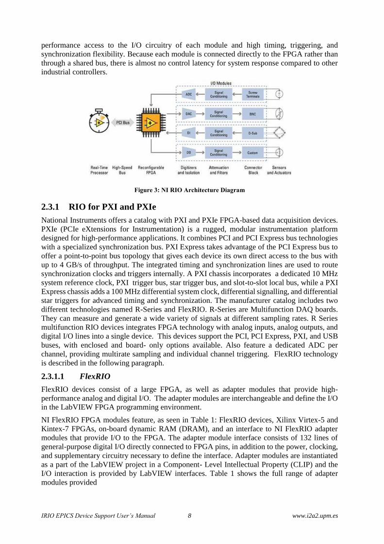
2.3 RIO platform architecture
The reconfigurable I/O (RIO) architecture combines the graphical programming environment
with a reconfigurable FPGA and I /O Modules for measurement and/or data acquisition, see
Figure 3. FPGAs permits creating highly customizable and reconfigurable platforms
implementing processing and control tasks with hardware circuitry and the capacity to perform
multi-parallel operations within a single clock cycle. The reconfigurable FPGA is the core of the
RIO hardware system architecture, it is directly connected to the I/O modules for high-
IRIO EPICS Device Support User’s Manual 8 www.i2a2.upm.es
performance access to the I/O circuitry of each module and high timing, triggering, and
synchronization flexibility. Because each module is connected directly to the FPGA rather than
through a shared bus, there is almost no control latency for system response compared to other
industrial controllers.
Figure 3: NI RIO Architecture Diagram
2.3.1 RIO for PXI and PXIe
National Instruments offers a catalog with PXI and PXIe FPGA-based data acquisition devices.
PXIe (PCIe eXtensions for Instrumentation) is a rugged, modular instrumentation platform
designed for high-performance applications. It combines PCI and PCI Express bus technologies
with a specialized synchronization bus. PXI Express takes advantage of the PCI Express bus to
offer a point-to-point bus topology that gives each device its own direct access to the bus with
up to 4 GB/s of throughput. The integrated timing and synchronization lines are used to route
synchronization clocks and triggers internally. A PXI chassis incorporates a dedicated 10 MHz
system reference clock, PXI trigger bus, star trigger bus, and slot-to-slot local bus, while a PXI
Express chassis adds a 100 MHz differential system clock, differential signalling, and differential
star triggers for advanced timing and synchronization. The manufacturer catalog includes two
different technologies named R-Series and FlexRIO. R-Series are Multifunction DAQ boards.
They can measure and generate a wide variety of signals at different sampling rates. R Series
multifunction RIO devices integrates FPGA technology with analog inputs, analog outputs, and
digital I/O lines into a single device. This devices support the PCI, PCI Express, PXI, and USB
buses, with enclosed and board- only options available. Also feature a dedicated ADC per
channel, providing multirate sampling and individual channel triggering. FlexRIO technology
is described in the following paragraph.
2.3.1.1 FlexRIO
FlexRIO devices consist of a large FPGA, as well as adapter modules that provide high-
performance analog and digital I/O. The adapter modules are interchangeable and define the I/O
in the LabVIEW FPGA programming environment.
NI FlexRIO FPGA modules feature, as seen in Table 1: FlexRIO devices, Xilinx Virtex-5 and
Kintex-7 FPGAs, on-board dynamic RAM (DRAM), and an interface to NI FlexRIO adapter
modules that provide I/O to the FPGA. The adapter module interface consists of 132 lines of
general-purpose digital I/O directly connected to FPGA pins, in addition to the power, clocking,
and supplementary circuitry necessary to define the interface. Adapter modules are instantiated
as a part of the LabVIEW project in a Component- Level Intellectual Property (CLIP) and the
I/O interaction is provided by LabVIEW interfaces. Table 1 shows the full range of adapter
modules provided

IRIO EPICS Device Support User’s Manual 9 www.i2a2.upm.es
Table 1: FlexRIO devices
Model Bus FPGA FPGA
Slices
FPGA
DSP Slices
FPGA
Memory
(Block
RAM)
Onboard
Memory
Supported by IRIO
Library V1.2.0
PXIe-7975R PXIe Kintex-7
XC7K410T 63,550 1,540 28,620 kbits 512 MB
PXIe-7966R PXIe Virtex-5 SX95T
-2 14,720 640 8,784 kbits 512 MB
PXIe-7965R PXIe Virtex-5 SX95T 14,720 640 8,784 kbits 512 MB
PXIe-7962R PXIe Virtex-5 SX50T 8,160 288 4,752 kbits 512 MB
PXIe-7961R PXIe Virtex-5 SX50T 8,160 288 4,752 kbits 0 MB
PXI-7954R PXI Virtex-5 LX110 17,280 64 4,608 kbits 128 MB
PXI-7953R PXI Virtex-5 LX85 12,960 48 3,456 kbits 128 MB
PXI-7952R PXI Virtex-5 LX50 7,200 48 1,728 kbits 128 MB
PXI-7951R PXI Virtex-5 LX30 4,800 32 1,152 kbits 0 MB
Table 2: FlexRIO adapter modules
Adapter module Supported by IRIO Library V1.2.0
NI 5791 100 MHz Bandwidth RF Transceiver Supported on demand
NI 5792 200 MHz Bandwidth RF Receiver Supported on demand
NI 5793 200 MHz Bandwidth RF Transmitter Supported on demand
NI 5781 100 MS/s Baseband Transceiver Supported on demand
NI 5782 250 MS/s IF Transceiver Supported on demand
NI 5731 12-Bit, 40 MS/s, 2 Channel Digitizer NI 5732
14-Bit, 80 MS/s, 2 Channel Digitizer Supported on demand
NI 5733 16-Bit, 120 MS/s, 2 Channel Digitizer NI
5734 16-Bit, 120 MS/s, 4 Channel Digitizer Supported on demand
NI 5751 14-Bit, 50 MS/s,16 Channel Digitizer Supported on demand
NI 5752 12-Bit, 50 MS/s, 32 Channel Digitizer Supported on demand
NI 5761 14-bit, 250 MS/s, 4 Channel Digitizer

IRIO EPICS Device Support User’s Manual 10 www.i2a2.upm.es
Adapter module Supported by IRIO Library V1.2.0
NI 5762 16-Bit, 250 MS/s, 2 Channel Digitizer Supported on demand
NI 5771 8-Bit, 3GS/s, 2 Channel Digitizer Supported on demand
NI 5772 12-Bit, 1.6GS/s, 2-Channel Digitizer Supported on demand
NI 5781 14-Bit, 100 MS/s,2 Channel Baseband
Transceiver
AT-1120 14-Bit, 2GS/s, 1-Channel Signal Generator Supported on demand
AT-1212 14-Bit, 1.2GS/s, 2-Channel Signal
Generator Supported on demand
NI 6581 200 Mbit/s, 54 Channel, Single Ended
Digital I/O
NI 6583 300 Mbit/s, 32 SE and 16 LVDS Channel
Digital I/O NI 6584 16 Mbit/s, 16 Ch, RS-422/RS-
485 Digital I/O
Supported on demand
NI 6585 200 Mbit/s, 32 Channel, LVDS Digital I/O
NI 6587 1 Gbit/s, 20 Channel, LVDS Digital I/O Supported on demand
NI 1483 Full Configuration Camera Link
2.3.2 RIO for Compact Embedded Applications
CompactRIO is a small, rugged RIO system for embedded and prototyping applications,
configurable with four, eight, and fourteen slot backplanes. It contains two main components: a
reconfigurable FPGA in a chassis, and the interchangeable industrial I/O modules. The
CompactRIO system can be connected to a computer using a PCIe link. The embedded chassis
contains the reconfigurable I/O FPGA chip directly connected to I/O modules that deliver diverse
high-performance I/O capabilities. cRIO chassis and I/O modules available are listed in Table 3:
Table 3: cRIO chassis and I/O modules available
cRIO item
9425: Sinking Digital Input 7 µs, 32 channels 12 / 24 V
9426: Sourcing Digital Input 7 µs, 32 channels 12 / 24 V
9476: Sourcing (500µs / 6-36V / 250 mA Digital Output 32
channels
9477: Sinking (8 µs / 5-60V / 625 mA) Digital Output 32
channels
9205: 32 x AI (16-bit, ±200mV to ±10V) 250 kS/s

IRIO EPICS Device Support User’s Manual 11 www.i2a2.upm.es
cRIO item
9264: 16 x AO (16-bit, ±10V, isolation 60 VDC) 25 kS/s/ch
(simultaneous)

IRIO EPICS Device Support User’s Manual 12 www.i2a2.upm.es
3 IRIO EPICS DEVICE SUPPORT INSTALLATION
This chapter explains: IRIO EPICS device support release information and history, the
Software/Hardware environment, how to install the required software, how to verify that the
software is installed correctly and how to uninstall it.
3.1 IRIO EPICS Device Support Release vs. Linux release
Table 4: EPICS device support vs. IRIO Library vs. Linux release
EPICS
Device
Support
Version
Release
Date
EPICS
device
Support
User Manual
IRIO
Library
Version
NI-RIO Linux
Device Driver Linux Version Supported
1.2.0 Jan-2017 1.2.0 1.2.0 15.0.0 ScientificLinux 6.8 and
RHEL6
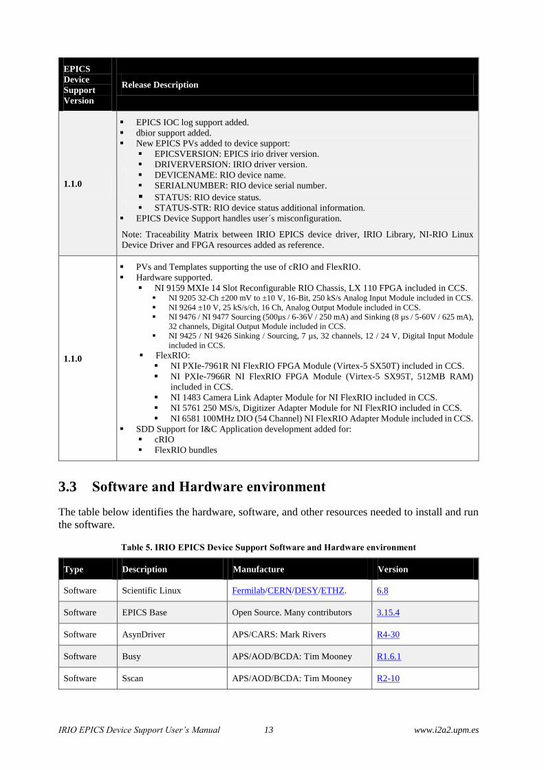
3.2 EPICS Device Support Release Notes
EPICS
Device
Support
Version
Release Description
1.2.0 IRIO EPICS Device Support supports its installation over ScientificLinux 6.8
1.1.2
Code revision to avoid segFault due to portName misconfiguration.
Solved problem with buffersize overwrite in image acquisition profile.
Fixed duplicate template versions causing sdd-sync to fail on database initialization
SR PV HOPR and DRVH fields modified from 100MS/s to 125MS/s.
DMAsOVERFLOWs PV SCAN field set to .1 second
1.1.1
I/O Intr scan support for AI and DI without use of DMA.
New EPICS PVs added to device support:
SR_AI_INTR: SamplingRate of AI# with SCAN=I/O Intr.
SR_DI_INTR: SamplingRate of DI# with SCAN=I/O Intr.
TSE=-2 supported. New irioTimeStamp function registered.
RIO boards serial name format change.
Due to a change in the low level NI-RIO Linux driver, the RIO device serial
number, given by lsrio.py command, that is used as a string argument to the driver
initialization call has to be prefixed with "0x" (case sensitive).
Old-nirioinit("RIO_0","01A2D92C","NI 9159","cRIOIO_9159","V1.1",1)
New-nirioinit("RIO_0","0x01A2D92C","NI 9159","cRIOIO_9159","V1.1",1)
Note: The serial number that must be used in nirioinit function call is always the
output of lsrio.py command
In SDD-Editor: compactRIO board renamed to NI9159 board.
IRIO EPICS Device Support User’s Manual 13 www.i2a2.upm.es
EPICS
Device
Support
Version
Release Description
1.1.0
EPICS IOC log support added.
dbior support added.
New EPICS PVs added to device support:
EPICSVERSION: EPICS irio driver version.
DRIVERVERSION: IRIO driver version.
DEVICENAME: RIO device name.
SERIALNUMBER: RIO device serial number.
STATUS: RIO device status. STATUS-STR: RIO device status additional information.
EPICS Device Support handles user´s misconfiguration.
Note: Traceability Matrix between IRIO EPICS device driver, IRIO Library, NI-RIO Linux
Device Driver and FPGA resources added as reference.
1.1.0
PVs and Templates supporting the use of cRIO and FlexRIO.
Hardware supported.
NI 9159 MXIe 14 Slot Reconfigurable RIO Chassis, LX 110 FPGA included in CCS. NI 9205 32-Ch ±200 mV to ±10 V, 16-Bit, 250 kS/s Analog Input Module included in CCS.
NI 9264 ±10 V, 25 kS/s/ch, 16 Ch, Analog Output Module included in CCS.
NI 9476 / NI 9477 Sourcing (500µs / 6-36V / 250 mA) and Sinking (8 µs / 5-60V / 625 mA),
32 channels, Digital Output Module included in CCS.
NI 9425 / NI 9426 Sinking / Sourcing, 7 µs, 32 channels, 12 / 24 V, Digital Input Module
included in CCS.
FlexRIO:
NI PXIe-7961R NI FlexRIO FPGA Module (Virtex-5 SX50T) included in CCS.
NI PXIe-7966R NI FlexRIO FPGA Module (Virtex-5 SX95T, 512MB RAM)
included in CCS.
NI 1483 Camera Link Adapter Module for NI FlexRIO included in CCS.
NI 5761 250 MS/s, Digitizer Adapter Module for NI FlexRIO included in CCS.
NI 6581 100MHz DIO (54 Channel) NI FlexRIO Adapter Module included in CCS.
SDD Support for I&C Application development added for:
cRIO
FlexRIO bundles
3.3 Software and Hardware environment
The table below identifies the hardware, software, and other resources needed to install and run
the software.
Table 5. IRIO EPICS Device Support Software and Hardware environment
Type Description Manufacture Version
Software Scientific Linux Fermilab/CERN/DESY/ETHZ. 6.8
Software EPICS Base Open Source. Many contributors 3.15.4
Software AsynDriver APS/CARS: Mark Rivers R4-30
Software Busy APS/AOD/BCDA: Tim Mooney R1.6.1
Software Sscan APS/AOD/BCDA: Tim Mooney R2-10

IRIO EPICS Device Support User’s Manual 14 www.i2a2.upm.es
Type Description Manufacture Version
Software Autosave APS/AOD/BCDA: Tim Mooney R5-7-1
Software Calc APS/AES/BCDA: Tim Mooney R3-6-1
Software IRIO library I2A2-UPM/ITER 1.2.0
Software NI-RIO Linux Device
Driver National Instruments 15.0.0
Software IRIO EPICS Device
Support ITER/UPM 1.2.0
Hardware PC (HDD > 10G, RAM >
2G) N/A N/A
Hardware
FlexRIO card with adapter
module or cRIO chassis
with I/O Modules
National Instruments N/A
3.4 Installing the IRIO EPICS Device Support
This section describes how to install and check the IRIO EPICS Device Support.
NOTE: NI-RIO Linux Driver 15.0 + EPICS Base + SynApps + IRIO Library must be previously installed. Click here for more information.
3.4.1 Obtaining the source code
IRIO EPICS Device Support software is hosted under GitHub, a web-based Git repository
hosting service.
Download IRIO EPICS Device Support software from: https://github.com/irio-
i2a2/irioepics/releases
3.4.2 Installing NI RIO EPICS Device Support
1. Untar irioepics-v1.2.0
2. Verify that irioepics-v1.2.0 includes at least, the following content:

IRIO EPICS Device Support User’s Manual 15 www.i2a2.upm.es
3. Move the folder irioepics-v1.2.0 to /opt/epics/support
4. Edit file /opt/epics/support/irioepics-v1.2.0/src/main/epics/configure/RELEASE setting
complete path of EPICS_BASE, SUPPORT and ASYN.
EPICS_BASE = /opt/epics/base-3.15.4
SUPPORT = /opt/epics/support
ASYN = $(SUPPORT)/asynR4-30
5. Navigate to /opt/epics/support/irioepics-v1.2.0 and execute:
$ sudo make
$ sudo make install
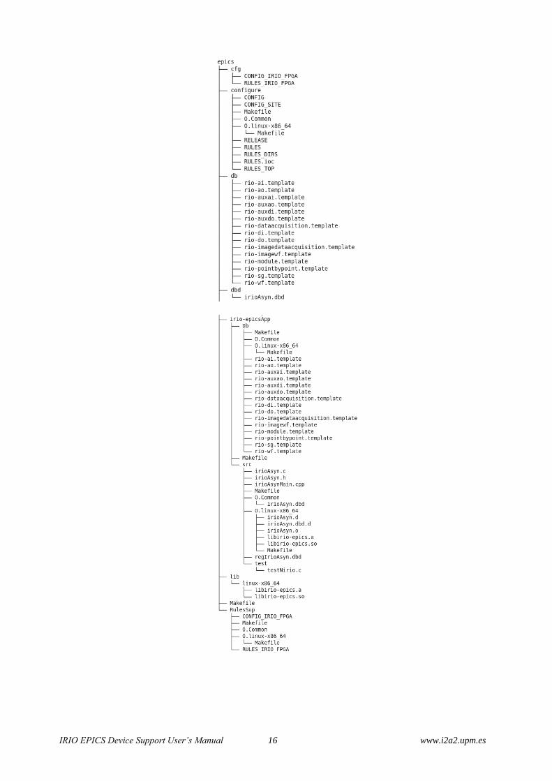
3.4.3 Verification of IRIO EPICS Device Support correct installation.
The IRIO EPICS Device Support is installed under /opt/epics/support folder.
Verify that /opt/epics/support/irioepics-v1.2.0/src/main/epics folder exist and includes at least
the following content:
IRIO EPICS Device Support User’s Manual 16 www.i2a2.upm.es

IRIO EPICS Device Support User’s Manual 17 www.i2a2.upm.es
3.5 Test of IRIO EPICS Device Support using IRIO EPICS
Sample Application
In order to test the IRIO EPICS Device Support an IRIO EPICS Sample Unit is available under
GitHub repository.
This unit includes five applications that test cRIO and FlexRIO platforms with all data
acquisition profiles:
cRIOIO: compactRIO application using direct I/O data acquisition profile.
cRIODMA: compactRIO application using DMA data acquisition profile.
fRIO5761: FlexRIO application using DMA data acquisition profile. This application
needs a PXIe7966/7965 + NI 5761 (AC/DC) adapter module. (Analog data acquisition)
fRIO6581: FlexRIO application using DMA data acquisition profile. This application
needs a PXIe7966/7965/7961 + NI 6581 adapter module. (Digital data acquisition)
fRIO1483: FlexRIO application using Image data acquisition profile. This application
needs a PXIe7966/7965 + NI 1483 adapter module. (Image data acquisition)
3.5.1 Obtaining the IRIO EPICS Sample Unit source code
IRIO EPICS Sample Unit is hosted under GitHub, a web-based Git repository hosting service.
Download IRIO EPICS Sample Unit from: https://github.com/irio-
i2a2/irio_epics_Sample/releases
3.5.2 Configure IRIO EPICS Sample Unit
After the IRIO EPICS Device Support is correctly installed, execute the following command to
list the RIO devices available.
$ lsni –v
The output will be similar to this, depending on the configuration of your PC.

IRIO EPICS Device Support User’s Manual 18 www.i2a2.upm.es
The nirioinit function must be modified with specific user’s configuration. The FPGA number
(i.e 7966, 7965, 7961,etc) and the Serial Number must be set correctly in st.cmd file of each IOC,
st.cmd file path is: /opt/epics/support/irio_epics_sample/iocBoot/ioc<application_name>, i.e.:
nirioinit("RIO_0","019ED079","NI 9159","cRIODAQDMA_9159","V1.1",1)
3.5.3 Compile IRIO EPICS Sample Unit and Run IOCs
Execute next command to compile the unit
$ cd /opt/epics/support/irio_epics_sample
$ sudo make
Execute next command to run IOCs
$ cd iocBoot/ioc<application_name>
$ ../../bin/linux_x86/<application_name>App st.cmd
3.6 Uninstalling IRIO EPICS Device Support
The user needs super user permission.
Uninstall the software executing next commands:
$ cd /opt/epics/support/irioepics-v1.2.0
$ sudo make clean uninstall

IRIO EPICS Device Support User’s Manual 19 www.i2a2.upm.es
4 IRIO EPICS DEVICE SUPPORT FUNCTIONALITY
This chapter describes the IRIO EPICS Device Support function to initialize a RIO device,
describes all data acquisition profiles supported and necessary templates on each profile and
describes all supported records.
4.1 RIO device initialization function
The nirioinit function available from the st.cmd allows the user to initialize the IRIO EPICS
device support.
int nirioinit(const char *namePort,const char *DevSerial,const char
*PXInirioModel, const char *projectName, const char *FPGAversion,int
verbosity)
This function registers all needed functionality of the ASYN driver used in this device support
and registers the port name provided with the function call. This function has to be added in the
usrPreDriverConf.cmd file, which is executed before the iocInit function in st.cmd file. Once the
function is executed the IRIO EPICS driver is ready to be used and records can connect using
asynDriver interfaces. All parameters needed are described in Table 6.
Parameters:
Table 6: Nirioinit function parameters description and restrictions.
Parameter
Name Description Code Restriction Parameter Example
namePort
Port name to associate
with the selected
device.
The namePort must follow next format:
RIO_<portnumber>
And <portNumber> must be a value from 0
to 9.
RIO_0
DevSerial Serial number of the
RIO device.
20 characters maximum. Must fix with the
serial number of the RIO device given by
lsrio.py command
0x0177A2AD
PXInirioMod
el RIO device model. 20 characters maximum. PXIe7966R
projectName
Name identifying the
design to load in the
FPGA.
No maximum characters, but the
PROJECT_NAME have to be the same
used for headerfile and bitfile.
NiFpga_PROJECT_NAME.h
NiFpga_PROJECT_NAME.lvbitx
cRIODAQDMA_9159
FPGAVersio
n
Version of the bitfile
used.
4 characters maximum. Must be with this
format: “Vx.y” x and y must be the same
values used in the FPGA design.
V1.1
verbosity Parameter for
displaying internal
No code restriction.
0: Do not print IRIO Library messages. 1

IRIO EPICS Device Support User’s Manual 20 www.i2a2.upm.es
Parameter
Name Description Code Restriction Parameter Example
driver messages for
debugging purposes.
Other: Print IRIO Library messages.
4.2 RIO device data acquisition profiles supported.
cRIO and FlexRIO devices support different data acquisition profiles. cRIO devices support two
different profiles: point by point data acquisition profile and DMA data acquisition profile.
FlexRIO devices supported profiles depend of the bundle. fRIO7966R-NI5761 and fRIO7961R-
NI6581 support DMA data acquisition profile and fRIO7966R-NI1483 supports Image data
acquisition profile.
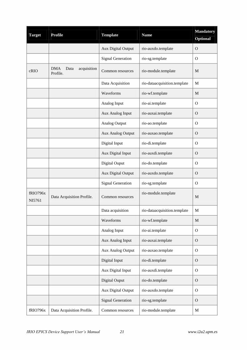
Each profile needs a set of templates depending on the application to be implemented in the
RIO’s FPGA. This sets of templates are described in Table 7. M means mandatory and O is
optional. The rio-module.template is mandatory to all platforms and all profiles. rio-
pointbypoint.template, rio-dataacquisition.template, rio-
imageacquisition.template, rio-wf.template and rio-imagewf.template are
also mandatory depending on the profile chosen. The remaining templates are optional and
depends on the resources implemented in the FPGA.
For instance, for a cRIO implementation of the point by point data acquisition profile, the user
has to instantiate the mandatory templates: rio-module.template and rio-
pointbypoint.template. The remaining templates are optional depending on the final
application implemented in the cRIO system. For instance, if the user is using a NI9205 (Analog
Input module with 32 channels) the user can instantiate this template and use up to 32 input
channels (if implemented in the FPGA). Every channel will be identified using the address.
Table 7: Template identification
Target Profile Template Name Mandatory
Optional
cRIO Point by Point Profile. Common resources rio-module.template
M
Point by Point
template rio-pointbypoint.template M
Analog Input rio-ai.template O
Aux Analog Input rio-auxai.template O
Analog Output rio-ao.template O
Aux Analog Output rio-auxao.template O
Digital Input rio-di.template O
Aux Digital Input rio-auxdi.template O
Digital Ouput rio-do.template O
IRIO EPICS Device Support User’s Manual 21 www.i2a2.upm.es
Target Profile Template Name Mandatory
Optional
Aux Digital Output rio-auxdo.template O
Signal Generation rio-sg.template O
cRIO DMA Data acquisition
Profile. Common resources rio-module.template M
Data Acquisition rio-dataacquisition.template M
Waveforms rio-wf.template M
Analog Input rio-ai.template O
Aux Analog Input rio-auxai.template O
Analog Output rio-ao.template O
Aux Analog Output rio-auxao.template O
Digital Input rio-di.template O
Aux Digital Input rio-auxdi.template O
Digital Ouput rio-do.template O
Aux Digital Output rio-auxdo.template O
Signal Generation rio-sg.template O
fRIO796x
NI5761 Data Acquisition Profile. Common resources
rio-module.template
M
Data acquisition rio-dataacquisition.template M
Waveforms rio-wf.template M
Analog Input rio-ai.template O
Aux Analog Input rio-auxai.template O
Aux Analog Output rio-auxao.template O
Digital Input rio-di.template O
Aux Digital Input rio-auxdi.template O
Digital Ouput rio-do.template O
Aux Digital Output rio-auxdo.template O
Signal Generation rio-sg.template O
fRIO796x Data Acquisition Profile. Common resources rio-module.template M

IRIO EPICS Device Support User’s Manual 22 www.i2a2.upm.es
Target Profile Template Name Mandatory
Optional
NI6581
Data acquisition rio-dataacquisition.template M
Waveforms rio-wf.template M
Aux Analog Input rio-auxai.template O
Aux Analog Output rio-auxao.template O
Digital Input rio-di.template O
Aux Digital Input rio-auxdi.template O
Digital Ouput rio-do.template O
Aux Digital Output rio-auxdo.template O
Signal –generation rio-sg.template O
fRIO 796x
NI1483 Image Acquisition Common resources
rio-module.template
M
Image Acquisition rio-
imageacquisition.template M
Image Waveform rio-imagewf.template M
Aux Analog Input rio-auxai.template O
Aux Analog Output rio-auxao.template O
Digital Input rio-di.template O
Aux Digital Input rio-auxdi.template O
Digital Ouput rio-do.template O
Aux Digital Output rio-auxdo.template O
4.3 Supported records
This section describes records used by IRIO EPICS Device Support. The records to be used
depend on the implementation done in the FPGA. Assuming that RIO’s FPGA contain a valid
design the records can connect to the different asynDriver interfaces for performing operations.
The number of records and their type is related with the profiles implemented in the FPGA.
Check the information provided by the designer to understand which PVs can be used. Process
Variable (PV) names follow I&C Signal Process Variable Naming Convention. This document
assumes that you are familiar with EPICS, and that EPICS Base, SynApps, iriolib-v1.2.0 and NI
RIO Linux Drriver 15.0 are installed. The IRIO EPICS driver is implemented as an Asyn port
driver. AsynDriver provides generic device support for standard EPICS records [RD4]. Refer to
IRIO EPICS Device Support User’s Manual 23 www.i2a2.upm.es
the Generic Device Support for EPICS records chapter for a detailed description. The Asyn
generic support uses the following conventions for DTYP and INP. OUT fields are the same as
INP.
field(DTYP,"asynXXX")
field(INP,"@asyn(portName,addr,timeout) drvParams")
where
XXX-Supported interface type name.
portName –Name of the port.
Addr – Address of the port. If addr is not specified the default is 0.
timeout - Timeout value for asynUser.timeout. If not specified the default is 1.0.
drvParams – Optional value passed to the low level driver via the asynDrvUser
interface.
For example:
record(ai, "$(PORT_NAME):AI$(ADDR ") {
field(SCAN, "1 second")
field(DTYP, "asynInt32")
field(INP, "@asyn($(PORT_NAME),$(ADDR))AI")
}
The IRIO EPICS driver implements the common, asynDrvUsr, asynOctet, asynInt8Array,
asynInt32, asynInt32Array, asynFloat64 and asynFloat32Array interfaces. The driver uses
addresses to select the channel when applicable. The interface parameters are described in
subsequent sections.
Explanations. Common resource Records must be used in all RIO-based
applications: cRIO and FlexRIO
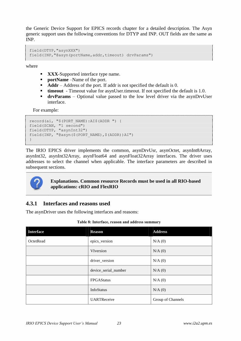
4.3.1 Interfaces and reasons used
The asynDriver uses the following interfaces and reasons:
Table 8: Interface, reason and address summary
Interface Reason Address
OctetRead epics_version N/A (0)
VIversion N/A (0)
driver_version N/A (0)
device_serial_number N/A (0)
FPGAStatus N/A (0)
InfoStatus N/A (0)
UARTReceive Group of Channels
IRIO EPICS Device Support User’s Manual 24 www.i2a2.upm.es
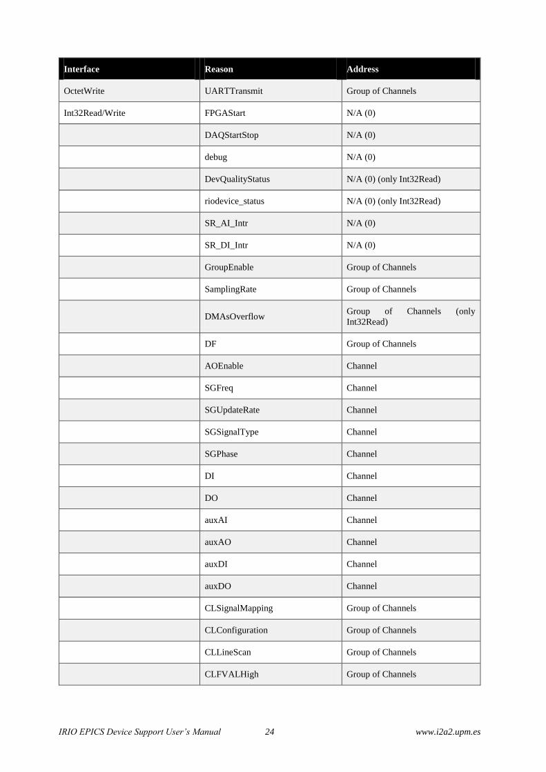
Interface Reason Address
OctetWrite UARTTransmit Group of Channels
Int32Read/Write FPGAStart N/A (0)
DAQStartStop N/A (0)
debug N/A (0)
DevQualityStatus N/A (0) (only Int32Read)
riodevice_status N/A (0) (only Int32Read)
SR_AI_Intr N/A (0)
SR_DI_Intr N/A (0)
GroupEnable Group of Channels
SamplingRate Group of Channels
DMAsOverflow Group of Channels (only
Int32Read)
DF Group of Channels
AOEnable Channel
SGFreq Channel
SGUpdateRate Channel
SGSignalType Channel
SGPhase Channel
DI Channel
DO Channel
auxAI Channel
auxAO Channel
auxDI Channel
auxDO Channel
CLSignalMapping Group of Channels
CLConfiguration Group of Channels
CLLineScan Group of Channels
CLFVALHigh Group of Channels

IRIO EPICS Device Support User’s Manual 25 www.i2a2.upm.es
Interface Reason Address
CLLVALHigh Group of Channels
CLDVALHigh Group of Channels
CLSpareHigh Group of Channels
UARTBreakIndicator Group of Channels (only
Int32Read)
UARTFrammingError Group of Channels (only
Int32Read)
UARTOverrunError Group of Channels (only
Int32Read)
CLSizeX Group of Channels
CLSizeY Group of Channels
Float64Write AO Channel
SGAmp Channel
Float64Read DeviceTemp Channel
AI Channel
AO Channel
SGAmp Channel
Float32ArrayRead CH Channel
Int8ArrayRead CH Channel
4.3.2 Records description
This section describes the functionality of all records included in each profile. The templates of
all records are included in Error! Reference source not found..
All record templates are located in irioepics/src/main/epics/irio-epicsApp/Db.
4.3.2.1 Records used by all profiles.
This section describes all mandatory PVs used to manage common resources in cRIO or FlexRIO
implementations. PVs described in this section are included in rio-module.template.
FPGASTART
Use this bo record to run the VI in the FPGA. Reason: FPGAStart.

IRIO EPICS Device Support User’s Manual 26 www.i2a2.upm.es
1 = ON value to trigger the initialization of the driver and the execution of the hardware
implemented in the FPGA.
0 = OFF value when the FPGA is not running or the driver is not initialized (in case the FPGA
was running with the same bitfile before launching the application).
Warning. FPGA just can be stopped with exit command from IOC shell.
FPGAVIVERSION
This stringin record allows to retrieve the version of the VI implemented in the FPGA. The VI
version contains a mayor and a minor value. Reason: VIversion.
DEVICETEMP
This ai record allows to read the temperature of the RIO device in Celsius degrees. Reason:
DeviceTemp.
DAQSTARTSTOP
This bo record starts/stop the data acquisition process in the RIO device. Reason: DAQStartStop.
1 = ON value starts the data acquisition.
0 = OFF value stops the data acquisition.
DEBUGMODE
This bo record sets the FPGA in debug mode. The behaviour of debug mode is defined by the
hardware developer. Check the specific implementation to know how debug mode is
implemented. With the debugmode activated the FPGA generates the values for the PVs. Reason:
debug.
1 = ON value enables debug mode.
0 = OFF value disables debug mode.
DEVQUALITYSTATUS
This ai record retrieves the status of the data acquisition devices in terms of quality. For instance
a DAQ device can be measuring poor signals degraded by a poor S/N ratio. DevQualityStatus
can give the user this information. The developer have to define the values obtained with this
PV. Reason: DevQualityStatus.
EPICSVERSION
This stringin record gives the IRIO EPICS driver version. Reason: epics_version.
IRIO EPICS Device Support User’s Manual 27 www.i2a2.upm.es
DRIVERVERSION
This stringin record gives the IRIO library version. Reason: driver _version.
DEVICENAME
This stringin record gives the RIO device name. RIO device name is provided by NI-RIO Linux
Device Driver. Reason: device_name.
SERIALNUMBER
This stringin record gives the RIO device serial number. Reason: serial_number.
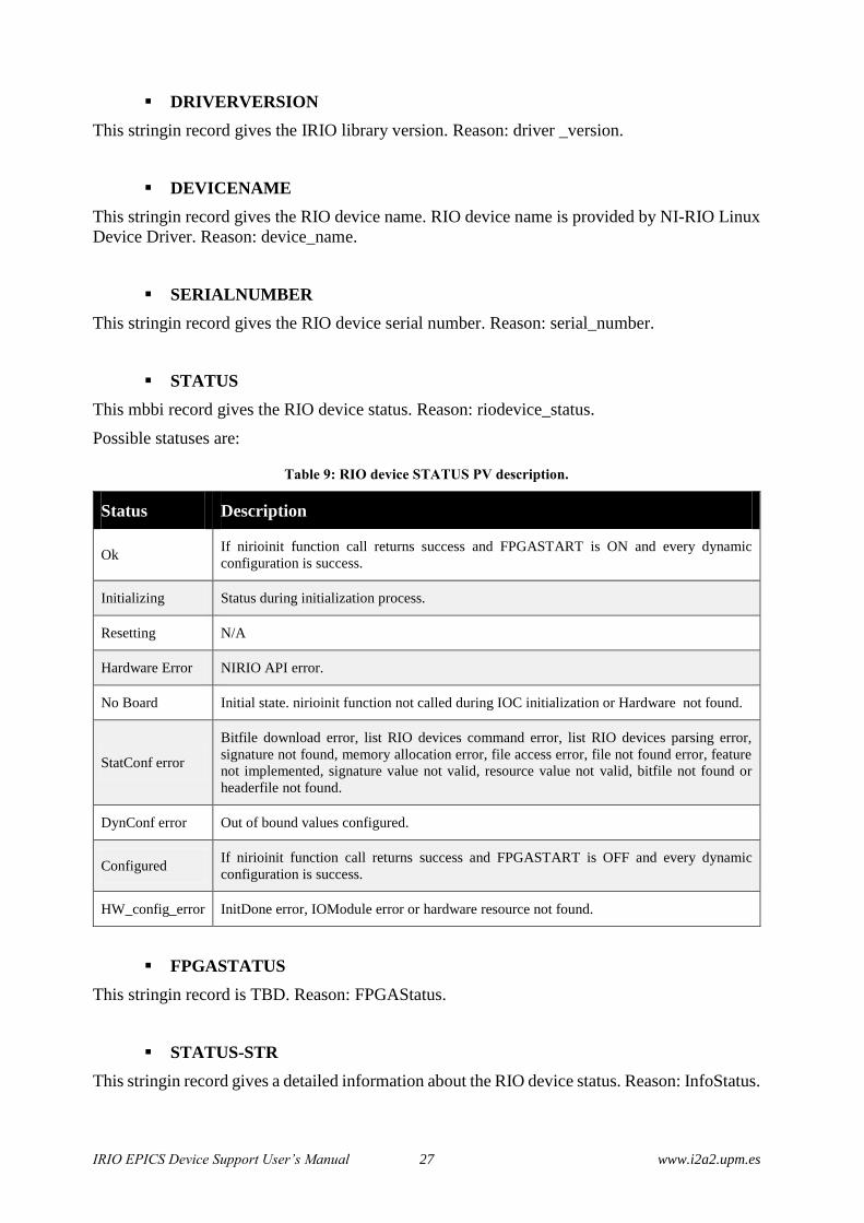
STATUS
This mbbi record gives the RIO device status. Reason: riodevice_status.
Possible statuses are:
Table 9: RIO device STATUS PV description.
Status Description
Ok If nirioinit function call returns success and FPGASTART is ON and every dynamic
configuration is success.
Initializing Status during initialization process.
Resetting N/A
Hardware Error NIRIO API error.
No Board Initial state. nirioinit function not called during IOC initialization or Hardware not found.
StatConf error
Bitfile download error, list RIO devices command error, list RIO devices parsing error,
signature not found, memory allocation error, file access error, file not found error, feature
not implemented, signature value not valid, resource value not valid, bitfile not found or
headerfile not found.
DynConf error Out of bound values configured.
Configured If nirioinit function call returns success and FPGASTART is OFF and every dynamic
configuration is success.
HW_config_error InitDone error, IOModule error or hardware resource not found.
FPGASTATUS
This stringin record is TBD. Reason: FPGAStatus.
STATUS-STR
This stringin record gives a detailed information about the RIO device status. Reason: InfoStatus.

IRIO EPICS Device Support User’s Manual 28 www.i2a2.upm.es
SR_AI_INTR
This ao record controls the sampling rate (Samples/s) used to read data by AI records with
SCAN=I/O Intr. See AI record description at point 4.3.2.5 to understand the use of this PV.
Reason: SR_AI_Intr
SR_DI_INTR
This ao record controls the sampling rate (Samples/s) used to read data by DI records with
SCAN=I/O Intr. See DI record description at point 4.3.2.5 to understand the use of this PV.
Reason: SR_DI_Intr
4.3.2.2 Records used by Point by Point profile
Point by Point profile can be used by cRIO implementations. It supports all mandatory PVs
included in rio-module.template and in rio-pointbypoint.template and PVs
included in optional templates described in Table 7. This section describes PVs included in rio-
pointbypoint.template.
SR_PBP
This ao record controls the sampling rate used for data acquisition. Reason: SamplingRate. Max
and Min values depend of hardware implementation. Maximum Sampling rate is the reference
frequency of the implementation and minimum sampling rate is the reference frequency divided
by 65535.
4.3.2.3 Records used by Data Acquisition profile
Data acquisition profile can be used by cRIO and FlexRIO (PXIe7966RNI5761 and
PXIe7961RNI6581 bundles) implementations. It supports all mandatory PVs included in rio-
module.template, rio-dataacquisition.template and rio-wf.template and
PVs included in optional templates described in Table 7.
This section describes PVs included in rio-dataacquisition.template. and rio-
wf.template (CH).
GROUPENABLE
This bo record enables/disables writing data from DMA Target to DMA Host. Reason:
GroupEnable.
1 = ENABLE value to enable data transfer.
0 = DISABLE value to disable data transfer.
SR
This ao record controls the sampling rate used for data acquisition. Reason: SamplingRate. Max
and Min values depend of hardware implementation. Maximum Sampling rate is the reference

IRIO EPICS Device Support User’s Manual 29 www.i2a2.upm.es
frequency of the implementation and minimum sampling rate is the reference frequency divided
by 65535.
DMAsOVERFLOW
This bi record retrieve the status of each DMAs overflow in the device. Reason: DMAsOverflow.
0 = CORRECT value if no DMAs overflow.
1 = OVERFLOW value if DMAs overflow.
DF
This ao record sets the block decimation factor of DMAs in the data acquisition process. Reason:
DF. Minimum DF value is 1 and Maximum DF value is 100000000.
CH
This waveform record acquires data from DMA Host in arrays of $(NSAMPLE) elements every
interrupt generated from the asyndriver. Reason: CH.
4.3.2.4 Records used by Image Data Acquisition Profile
Image data acquisition profile can be used ONLY with FlexRIO PXIe7966RNI1483 bundle. It
supports all mandatory PVs included in rio-module.template, rio-
imageacquisition.template and rio-imagewf.template and PVs included in
optional templates described in Table 7. This section describes PVs included in rio-
imageacquisition.template. (GROUPENABLE, DMAsOVERFLOW, DF,
SIGGNALMAPPING, CONFIGURATION, LINESCAN, FVALHIGH, LVALHIGH,
DVALHIGH, SPAREHIGH, UARTRECEIVE, UARTTRANSMIT, UARTBREAK,
UARTFRAMEeRR, UARTOVERRUN, SIZEX and SIZEY) and rio-imagewf.template
(CH, IMAGE AND IMAGESIZE)
GROUPENABLE
This bo record enables or disables writing data from DMA Target to DMA Host. Reason:
GroupEnable.
1 = ENABLE value to enable data transfer.
0 = DISABLE value to disable data transfer.
DMAsOVERFLOW
This bi record retrieve the status of each DMAs overflow in the device. Reason: DMAsOverflow.
0 = CORRECT value if no DMAs overflow.
1 = OVERFLOW value if DMAs overflow.
DF

IRIO EPICS Device Support User’s Manual 30 www.i2a2.upm.es
This ao record sets the block decimation factor of DMAs in the data acquisition process. Reason:
DF. Minimum DF value is 1 and Maximum DF value is 100000000.
SIGNALMAPPING
This mbbo record sets the signal mapping for Cameralink. Reason: CLSignalMapping
0 = STANDARD value to configure image transfer for cameras using standard signal mapping
on Base, Medium and Full modes.
1 = BASLER10TAP value to configure image transfer for cameras using Basler signal mapping
on Extended mode with 80 bits per pixel clock.
2 = VOSKHULER10TAP value to configure image transfer for cameras using Voskhuler signal
mapping on Full mode with 80 bits per pixel clock
CONFIGURATION
This mbbo record sets the configuration for Cameralink interface. Reason: CLConfiguration.
0 = BASE value to configure image transfer using CameraLink Base mode (1 cable).
1 = MEDIUM value to configure image transfer using CameraLink Medium mode (2 cables).
2 = FULL value to configure image transfer using CameraLink Full, Extended, and 10-tap
modes (2 cables).
LINESCAN
This bo record enables/disables the line scan for Cameralink. Reason: CLConfiguration.
1 = ENABLE value to set for line scan cameras.
0 = DISABLE value to set for frame scan cameras.
FVALHIGH
This bo record enables/disables the logic level used for the FVALHigh signal. Reason:
CLFVALHigh.
1 = ENABLE value to set for cameras using FVAL signal on active high mode.
0 = DISABLE value to set for cameras using FVAL signal on active low mode.
LVALHIGH
This bo record enables/disables the logic level used for the LVALHigh signal. Reason:
CLLVALHigh.
1 = ENABLE value to set for cameras using LVAL signal on active high mode.
0 = DISABLE value to set for cameras using LVAL signal on active low mode.
DVALHIGH

IRIO EPICS Device Support User’s Manual 31 www.i2a2.upm.es
This bo record enables/disables the logic level used for the DVALHigh signal. Reason:
CLDVALHigh.
1 = ENABLE value to set for cameras using DVAL signal on active high mode.
0 = DISABLE value to set for cameras using DVAL signal on active low mode.
SPAREHIGH
This bo record enables/disables the logic level used for the Spare-High signal. Reason:
CLSpareHigh.
1 = ENABLE value to set for cameras using Spare signal on active high mode.
0 = DISABLE value to set for cameras using Spare signal on active low mode.
UARTRECEIVE
The stringin record read the last buffer read by the cameralink uart. Reason: UARTReceive.
UARTTRANSMIT
This stringout record allows to write a buffer in the cameralink uart. Reason: UARTTransmit.
UARTBREAK
This bi record gets if UART break indicator is active or not. Reason: UARTBreakIndicator.
0 = UARTCORRECT value for correct UART message reception.
1 = UARTBREAK value when the received byte was part of a break condition (RX signal held
low longer than expected),
UARTFRAMEeRR
This bi record gets if UART break frame error is active or not. Reason: UARTFrammingError.
0 = UARTCORRECT value for correct UART message reception.
1 = UARTFRAMEERROR value when the received byte did not have valid stop bit.
UARTOVERRUN
This bi record gets if UART overrun error is active or not. Reason: UARTOverrunError.
0 = UARTCORRECT value when no UART data have been lost.
1 = UARTOVERRUN value when UART data have been lost due to a full receive buffer.
SIZEX
This longout record sets the image size for X axis. Reason: CLSizeX. Minimum SizeX value is
1 and Maximum SizeX value is 1690.

IRIO EPICS Device Support User’s Manual 32 www.i2a2.upm.es
SIZEY
This longout record sets the image size for Y axis. Reason: CLSizeY. Minimm SizeY value is 1
and Maximum SizeY value is 1710.
CH
This waveform record gets the complete array of the image acquired by the framegrabber.
Reason: CH.
IMAGE
This subarray record gets the image of X*Y.
IMAGESIZE
This calcout record computes the image size X*Y.
4.3.2.5 Records used for optional resources
This section describes all PVs included in optional templates. See Table 10.
Table 10: Summary of PVs included in optional templates.
Optional template PVs included
rio-ai.template AI
rio-auxai.template auxAI
rio-ao.template AO and AOENABLE
rio-auxao.template auxAO
rio-di.template DI
rio-auxdi.template auxDI
rio-do.template DO
rio-auxdo.template auxDO
rio-sg.template SGUPDATERATE, SGAMP, SGFREQ and
SGPHASE
AI
This ai record has the value corresponding to an analog input. Reason: AI.
SCAN field supports “I/O Intr” in IRIO EPICS Device Support V1.1.1. The
“I/O Intr” functionality is implemented using a periodic thread reading the
AI FPGA terminals, because NI-RIO Linux Device Driver does not provide

IRIO EPICS Device Support User’s Manual 33 www.i2a2.upm.es
an interrupt functionality. The period of this thread is controlled by the
value specified in the PV named SR_AI_INTR.
auxAI
This ai record has the value corresponding to an auxiliary analog input. Reason: auxAI.
AO
This ao record value is the output of the analog output channel in the I/O Module. Only if
AOEnable is set to 1 = ENABLE, the AO value will be outputted throw the analog output channel
of the I/O Module. Reason: AO.
AOENABLE
This bo record enables/disables the output of the analog output channel in the I/O Module.
Reason: AOEnable.
0 = DISABLE value disables the output throw the analog output channel.
1 = ENABLE value enables the output throw the analog output channel.
auxAO
This ao record allow to write an internal register in the FPGA (auxiliary control). Reason: auxAO.
DI
This bi record has the value of the digital input. Reason: DI.
SCAN field supports “I/O Intr” in IRIO EPICS Device Driver V1.1.1. The
“I/O Intr” functionality is implemented using a periodic thread reading the
DI FPGA terminals, because NI-RIO Linux Device Driver does not provide
an interrupt functionality. The period of this thread is controlled by the
value specified in the PV named SR_DI_INTR.
auxDI
This bi record has the value of the auxiliary digital input. Reason auxDI.
DO
This bo record writes a value on the digital output. Reason: DO.
auxDO
This bo record writes a value on the auxiliary digital output. Reason: auxDO.

IRIO EPICS Device Support User’s Manual 34 www.i2a2.upm.es
SIGNAL GENERATOR RECORDS
o SGUPDATERATE
This ao record allows to write the update rate in the signal generator. Engineering units
= Samples per second (S/s). Reason: SGUpdateRate.
o SGFREQ
This ao record sets the frequency of the signal generated in the FPGA. Engineering unit
= Herts (Hz). Reason: SGFreq.
o SGPHASE
This ao record sets the phase of the signal generated in the FPGA. Reason: SGPhase.
o SGAMP
This ao record sets the amplitude of the signal generated in the FPGA. Engineering unit = Volts
(V). Reason: SGAmp.
o SGSIGNALTYPE
This mbbo record configures the shape of the signal generated in FPGA. Reason: SGSignaltype.
0 = DC signal is generated in the internal signal generator.
1 = SINE signal is generated in the internal signal generator.
2 = SQUARE signal is generated in the internal signal generator.
3 = TRIANGLE signal is generated in the internal signal generator.
IRIO EPICS Device Support User’s Manual 35 www.i2a2.upm.es
5 IRIO EPICS DEVICE SUPPORT USE IN I&C
APPLICATION
This chapter describes how to use the IRIO EPICS driver (Asyn port driver) in an I&C
application and describes mandatory steps that will allow the proper software initialization and
the creation of EPICS variables interfaced with the device driver.
5.1 Download LabVIEW templates to create EPICS Application
examples
Download LabVIEW Templates from: https://github.com/irio-
i2a2/IRIO_LabVIEW_Test_Templates/releases and untar the package.
5.2 Create I&C Applications manually
This section describes how to create manually a software unit containing multiple applications
using RIO devices. The irio_epics_sample application build in this section can be found in the
following GitHub repository:
https://github.com/irio-i2a2/irio_epics_sample/releases
Users can find useful this unit to see how to configure properly their own examples.
5.2.1 Create the sample unit
Open a terminal window and execute next commands to create the unit folder.
$mkdir irio_epics_sample
$cd irio_epics_sample
Next command provides a list of the application templates available.
<base/>bin/<arch>/makeBaseApp.pl -l
$/opt/epics/base-3.15.4/bin/linux-x86/makeBaseApp.pl -l
Five different applications can be created (including IOCs) to use all IRIO EPICS Device
Support supported platforms and data acquisition profiles.
1. CompactRIO application (including IOC) using Point by point data acquisition profile.
Next command creates the application directories.
<base/>bin/<arch>/makeBaseApp.pl –t <type> <application_name>
Select: <type> = example ; <app> = cRIOIO
$/opt/epics/base-3.15.4/bin/linux-x86/makeBaseApp.pl –t example
cRIOIO
Next command creates the IOC boot directories.
<base/>bin/<arch>/makeBaseApp.pl –i –t <type> <ioc>
Select: <type> = example ; <ioc> = cRIOIO

IRIO EPICS Device Support User’s Manual 36 www.i2a2.upm.es
$/opt/epics/base-3.15.4/bin/linux-x86/makeBaseApp.pl –i –t example
cRIOIO
2. CompactRIO application (including IOC) using DMA data acquisition profile.
$/opt/epics/base-3.15.4/bin/linux-x86/makeBaseApp.pl –t example
cRIODMA
$/opt/epics/base-3.15.4/bin/linux-x86/makeBaseApp.pl –i –t example
cRIODMA
3. FlexRIO application (including IOC) using PXIe7966-NI5761 bundle and data acquisition
profile.
$/opt/epics/base-3.15.4/bin/linux-x86/makeBaseApp.pl –t example
fRIO5761
$/opt/epics/base-3.15.4/bin/linux-x86/makeBaseApp.pl –i –t example
fRIO5761
4. FlexRIO application (including IOC) using PXIe7965-NI6581 bundle and data acquisition
profile.
$/opt/epics/base-3.15.4/bin/linux-x86/makeBaseApp.pl –t example
fRIO6581
$/opt/epics/base-3.15.4/bin/linux-x86/makeBaseApp.pl –i –t example
fRIO6581
5. FlexRIO application (including IOC) using PXIe7966-NI1483 bundle and image data
acquisition profile.
$/opt/epics/base-3.15.4/bin/linux-x86/makeBaseApp.pl –t example
fRIO1483
$/opt/epics/base-3.15.4/bin/linux-x86/makeBaseApp.pl –i –t example
fRIO1483
5.2.2 Configure the unit, the application and the IOC
Next paragraphs explain how to configure each application and each IOC included in a software
unit. If your software unit contains more than one App repeat the process described below.
The necessary steps to configure the sample unit include:
1) Configuration of RELEASE file.
2) Configuration of Db.
3) The addition of the LabVIEW project with the FPGA implementation inside the sample
unit.
4) The configuration of the Makefiles to find necessary libraries, the bitfile and headerfile,
and to build record databases.
5) The configuration of the RIO device initialization function.
5.2.2.1 Configure RELEASE file
Navigate to epics_irio_sample/configure.

IRIO EPICS Device Support User’s Manual 37 www.i2a2.upm.es
Edit RELEASE file adding next lines at the end of the file:
EPICS_BASE=/opt/epics/base-3.15.4
SUPPORT = /opt/epics/support
ASYN = $(SUPPORT)/asyn4-30
IRIO_LIB = $(SUPPORT)/iriolib-v1.2.0/src/main/epics
IRIO_EPICS = $(SUPPORT)/irioepics-v1.2.0/src/main/epics
5.2.2.2 Configure DB
Navigate to epics_irio_sample/<application_name>App/Db
Edit Makefile as follows:
TOP=../..
include $(TOP)/configure/CONFIG
#----------------------------------------
# ADD MACRO DEFINITIONS AFTER THIS LINE
#----------------------------------------------------
# Optimization of db files using dbst (DEFAULT: NO)
#DB_OPT = YES
#----------------------------------------------------
# Create and install (or just install)
# databases, templates, substitutions like this
#----------------------------------------------------
# If <anyname>.db template is not named <anyname>*.template add
# <anyname>_TEMPLATE = <templatename>
include $(TOP)/configure/RULES
#----------------------------------------
# ADD RULES AFTER THIS LINE
Db loaded in the example have been deleted. Our sample application will load the records
database through substitution files loaded in st.cmd file
5.2.2.3 Include LabVIEW code to the application
Create a new folder called LV<application_name> in the following path,
epics-irio-sample/src/main/epics/<application_name>App/
Copy the LV project folder of each application from the IRIO_LabVIEW_Test_Templates github
repository downloaded in section 5.1
This folder contains the LabVIEW for FPGA project developed for this specific application. The
content of the LV<application_name> folder must include a folder named “FPGA_Bitfiles”. It
contains the bitfile and the headerfile. The name of this folder is mandatory.
This is the only valid method to include LabVIEW project in a sample
application.
5.2.2.4 Include necessary libraries and LabVIEW resources in the App.
Edit the application Makefile located in:
irio_epics_sample/src/main/epics/<application_name>App/src

IRIO EPICS Device Support User’s Manual 38 www.i2a2.upm.es
Add the lines highlighted in bold to include the LabVIEW resources and necessary libraries in
the application.
TOP=../..
include $(TOP)/configure/CONFIG
#----------------------------------------
# ADD MACRO DEFINITIONS AFTER THIS LINE
#=============================
# Declare LabVIEW resources
IRIO_FPGA_DIR = LV<application_name>/FPGA_Bitfiles
IRIO_FPGA += NiFpga_<LV_project_name>.h NiFpga_<LV_project_name>.lvbitx
#=============================
#=============================
# Build the IOC support library
PROD_IOC += <application_name>
# <application_name>.dbd will be created and installed
DBD += <application_name>.dbd
# <application_name>.dbd will be made up from base.dbd and module dbds listed
below:
<application_name>_DBD += base.dbd
# <application_name>_registerRecordDeviceDriver.cpp derives from
<application_name>.dbd
<application_name>_SRCS += <application_name>_registerRecordDeviceDriver.cpp
# Build the main IOC entry point on workstation OSs.
<application_name>_SRCS_DEFAULT += <application_name>Main.cpp
<application_name>_SRCS_vxWorks += -nil-
#=============================
# Add support for the following uncommented modules:
# # ASYN
<application_name>_DBD += asyn.dbd
<application_name>_DBD += drvAsynSerialPort.dbd
<application_name>_DBD += drvAsynIPPort.dbd
<application_name>_LIBS += asyn
## IRIO
<application_name>_DBD += irioAsyn.dbd
<application_name>_LIBS += irio-epics
-include ../*.snlprog
#=============================
# Finally link to the EPICS Base libraries
<application_name>_LIBS += $(EPICS_BASE_IOC_LIBS)
#=============================
include $(TOP)/configure/RULES
#----------------------------------------
# ADD RULES AFTER THIS LINE

IRIO EPICS Device Support User’s Manual 39 www.i2a2.upm.es
This is the only valid method to include headerfiles and bitfiles in the sample
application.
5.2.2.5 Add substitution files
Add necessary substitution files to the application. Every substitution file must contain as many
calls to the templates as resources are implemented in the FPGA.
Substitution files must be named as follows: XXXXXX.substitution.
Each instantiation of the template load once the template and all the PVs defined inside.
Example of substitution file for rio-module.template instantiated for a cRIO platform.
file “$(IRIO_EPICS)/db/rio-module.template” {
pattern
{
BOARDTYPE,
BOARDTYPEIDX,
CBS1,
CBS2,
MODULEIDX
}
{
“NI9159”,
“0”,
“TEST”,
“FCT0”,
“0”
}
}
The template has been instantiated once, so PVs loaded are: FPGASTART, EPICSVERSION,
DEVICETEMP, DAQSTARTSTOP, DEBUGMODE, DEVQUALITYSTATUS,
FPGAVIVERSION, DRIVERVERSION, DEVICENAME, SERIALNUMBER,
FPGASTATUS, STATUS-STR and STATUS
Example of substitution file for rio-sg.template for a PXIe-7966RNI5761 platform.
file “$(IRIO_EPICS)/db/rio-sg.template” {
pattern
{
BOARDTYPE,
BOARDTYPEIDX,
CBS1,
CBS2,
CHIDX,
MODULEIDX,
HOPR_SGUPDATERATE,
LOPR_SGUPDATERATE,
DRVH_SGUPDATERATE,
DRVL_SGUPDATERATE,
HOPR_SGFREQ,

IRIO EPICS Device Support User’s Manual 40 www.i2a2.upm.es
LOPR_SGFREQ,
DRVH_SGFREQ,
DRVL_SGFREQ,
HOPR_SGPHASE,
LOPR_SGPHASE,
DRVH_SGPHASE,
DRVL_SGPHASE,
HOPR_SGAMP,
LOPR_SGAMP,
DRVH_SGAMP,
DRVL_SGAMP,
}
{
“5761”
“0”
“TEST”
“FCT0”
“0”
“0”
“100000000”
“0”
“100000000”
“0”
“10000000”
“0”
“10000000”
“0”
“360”
“0”
“360”
“0”
“1”
“-1”
“1”
“-1”
}
{
“5761”
“0”
“TEST”
“FCT0”
“1”
“0”
“100000000”
“0”
“100000000”
“0”
“10000000”
“0”
“10000000”
“0”
“360”
“0”
“360”
“0”
“1”
“-1”
“1”
“-1”

IRIO EPICS Device Support User’s Manual 41 www.i2a2.upm.es
}
}
The template has been instantiated twice, so PVs loaded are: SGUPDATERATE0,
SGUPDATERATE1, SGFREQ0, SGFREQ1, SGAMP0, SGAMP1, SGPHASE0, SGPHASE1,
SGSIGNALTYPE0 and SGSIGNALTYPE1.
The complete list of substitution files for each application, that matches with resources
implemented in LabVIEW projects downloaded in section 5.1, can be found at irio_epics_sample
github repository downloaded in section 5.2.2
Copy substitution files of each application in
irio_epics_sample/iocBoot/ioc<application_name> folder
5.2.2.6 Configure st.cmd file with RIO device initialization function and load
records.
Navigate to irio_epics_sample/iocBoot/ioc<application_name>
Edit with a text editor the st.cmd file adding following code.
#-======================================================================
< envPaths
epicsEnvSet("EPICS_CA_MAX_ARRAY_BYTES","170000")
cd "${TOP}"
#############################################
## Register all support components ##
#############################################
dbLoadDatabase "dbd/cRIOPBP.dbd"
cRIOPBP_registerRecordDeviceDriver pdbbase
#############################################
## IRIO Device Initialization Function ##
#############################################
nirioinit("RIO_<x>","<RIO SN>","RIO Model", "LabVIEWProject","Vx.x",1)
#############################################
## Loading substitution files ##
#############################################
cd "$(TOP)/iocBoot/$(IOC)"
dbLoadTemplate("PCF0-rio-module.substitution")
dbLoadTemplate("PCF0-rio-ai.substitution")
dbLoadTemplate("PCF0-rio-ao.substitution")
dbLoadTemplate("PCF0-rio-di.substitution")
dbLoadTemplate("PCF0-rio-do.substitution")
dbLoadTemplate("PCF0-rio-auxai.substitution")
dbLoadTemplate("PCF0-rio-auxao.substitution")
dbLoadTemplate("PCF0-rio-auxdi.substitution")
dbLoadTemplate("PCF0-rio-auxdo.substitution")
dbLoadTemplate("PCF0-rio-pointbypoint.substitution")
#############################################
## IOC Logging ##
#############################################
iocLogInit

IRIO EPICS Device Support User’s Manual 42 www.i2a2.upm.es
#############################################
## IOC initialization ##
#############################################
cd "${TOP}/db"
iocInit
See section 4.1 for more details about parameters used.
Serial number of your RIO device is obtained executing lsrio.py command in
a terminal window in the fast controller.
5.2.2.7 Compile the unit
Compile the unit
$ make
5.2.2.8 Run the application
To run one application use the following command:
$ cd irio_epics_sample/iocBoot/ioc<application_name>
$ ../../bin/<arch>/<application_name> st.cmd
5.2.2.9 OPI Panels to manage RIO devices with CSS
Download and install any Control System Studio software distribution
Open OPI panels included in irio_epics_sample github repository to control de RIO device
selected, start/stop data acquisition, and visualize the data acquired.

IRIO EPICS Device Support User’s Manual 43 www.i2a2.upm.es
Appendix A RECORD TEMPLATES
This section provides details of the records used in the templates which are part of the IRIO
EPICS Device Support (version 1.2.0 or higher). In the substitution files, the following macros
are defined:
CBS1: Control break down structure level 1 name
CBS2: Control break down structure level 2 name
BOARDTYPEIDX: Controller index
MODULEIDX: Module index
o ASYNPORT name will be RIO_$(MODULEIDX), i.e. RIO_0 for module
instance 0.
CHIDX : Channel number
GRIDX: Group number
NSAMPLES: Number of samples in waveforms.
Other MACROS are defined in SignalGenerator template related with
HOPR,LOPR,DRVH and DRVL for SGAMP, SGFREQ, SGUPDATERATE AND
SGPHASE.
A.1. Records of common resources for all RIO devices
FPGASTART
record(bo,"$(CBS1)-$(CBS2)-HWCF:$(BOARDTYPE)-$(BOARDTYPEIDX)-FPGASTART"){
field(DESC,"FPGA Start.")
field(DTYP,"asynInt32")
field(OUT,"@asyn(RIO_$(MODULEIDX),0)FPGAStart")
field(PINI,"NO")
field(ZNAM,"OFF")
field(ONAM,"ON")
}
FPGAVIVERSION
record(stringin,"$(CBS1)-$(CBS2)-HWCF:$(BOARDTYPE)-$(BOARDTYPEIDX)-
FPGAVIVERSION"){
field(DESC,"Bitfile version")
field(DTYP,"asynOctetRead")
field(INP,"@asyn(RIO_$(MODULEIDX),0)VIversion")
field(PINI,"YES")
}
DEVICETEMP
record(ai,"$(CBS1)-$(CBS2)-HWCF:$(BOARDTYPE)-$(BOARDTYPEIDX)-
DEVICETEMP"){
field(DESC,"FPGA Temperature")
field(DTYP,"asynFloat64")
field(INP,"@asyn(RIO_$(MODULEIDX),0)DeviceTemp")
field(SCAN,"1 second")
field(PREC,"2")
field(PINI,"YES")
field(LINR,"NO CONVERSION")
field(EGU,"C Degrees")

IRIO EPICS Device Support User’s Manual 44 www.i2a2.upm.es
}
DAQSTARTSTOP
record(bo,"$(CBS1)-$(CBS2)-HWCF:$(BOARDTYPE)-$(BOARDTYPEIDX)-
DAQSTARTSTOP"){
field(DESC,"Controls DAQ Start/Stop ")
field(DTYP,"asynInt32")
field(OUT,"@asyn(RIO_$(MODULEIDX),0)DAQStartStop")
field(PINI,"NO")
field(ZNAM,"OFF")
field(ONAM,"ON")
}
DEBUGMODE
record(bo,"$(CBS1)-$(CBS2)-HWCF:$(BOARDTYPE)-$(BOARDTYPEIDX)-DEBUGMODE"){
field(DESC,"Controls FPGA DebugMode")
field(DTYP,"asynInt32")
field(OUT,"@asyn(RIO_$(MODULEIDX),0)debug")
field(PINI,"NO")
field(ZNAM,"OFF")
field(ONAM,"ON")
}
DEVQUALITYSTATUS
record(ai,"$(CBS1)-$(CBS2)-HWCF:$(BOARDTYPE)-$(BOARDTYPEIDX)-
DEVQUALITYSTATUS"){
field(DESC,"Info of errors in acquisition process")
field(DTYP,"asynInt32")
field(INP,"@asyn(RIO_$(MODULEIDX),0)DevQualityStatus")
field(SCAN,"1 second")
field(PINI,"YES")
}
EPICSVERSION
record(ai,"$(CBS1)-$(CBS2)-HWCF:$(BOARDTYPE)-$(BOARDTYPEIDX)-
EPICSVERSION"){
field(DESC,"Epics-irio driver version")
field(DTYP,"asynOctetRead")
field(INP,"@asyn(RIO_$(MODULEIDX),0)epics_version")
field(PINI,"YES")
}
DRIVERVERSION
record(ai,"$(CBS1)-$(CBS2)-HWCF:$(BOARDTYPE)-$(BOARDTYPEIDX)-
DRIVERVERSION"){
field(DESC,"IRIO driver version")
field(DTYP,"asynOctetRead")
field(INP,"@asyn(RIO_$(MODULEIDX),0)driver_version")
field(PINI,"YES")

IRIO EPICS Device Support User’s Manual 45 www.i2a2.upm.es
}
DEVICENAME
record(ai,"$(CBS1)-$(CBS2)-HWCF:$(BOARDTYPE)-$(BOARDTYPEIDX)-
DEVICENAME"){
field(DESC,"RIO device name")
field(DTYP,"asynOctetRead")
field(INP,"@asyn(RIO_$(MODULEIDX),0) device_name ")
field(PINI,"YES")
}
SERIALNUMBER
record(ai,"$(CBS1)-$(CBS2)-HWCF:$(BOARDTYPE)-$(BOARDTYPEIDX)-
SERIALNUMBER"){
field(DESC,"RIO device serial number")
field(DTYP,"asynOctetRead")
field(INP,"@asyn(RIO_$(MODULEIDX),0) serial_number ")
field(PINI,"YES")
}
STATUS
record(mbbi,"$(CBS1)-$(CBS2)-HWCF:$(BOARDTYPE)-$(BOARDTYPEIDX)-STATUS"){
field(DESC,"$(BOARDTYPE).$(BOARDTYPEIDX) Board Status")
field(DTYP,"asynInt32")
field(INP,"@asyn(RIO_$(MODULEIDX),0) riodevice_status ")
field(SCAN,"i/o iNTR")
field(ZRVL,"0")
field(ZRST,"Ok")
field(ZRSV,"NO_ALARM")
field(ONVL,"1")
field(ONST,"Initializing")
field(ONSV,"MINOR")
field(TWVL,"2")
field(TWST,"Resetting")
field(TWSV,"MINOR")
field(THVL,"3")
field(THST,"Hardware error")
field(THSV,"MAJOR")
field(FRVL,"4")
field(FRST,"No Board")
field(FRSV,"MAJOR")
field(FVVL,"5")
field(FVST,"StatConf error")
field(FVSV,"MAJOR")
field(SXVL,"6")
field(SXST,"DynConf error")
field(SXSV,"MAJOR")
field(SVVL,"7")
field(SVST,"Configured")
field(SVSV,"NO_ALARM")
field(EIVL,"8")
field(EIST,"HW_config_error")
field(EISV,"MAJOR")
field(PINI, "YES")

IRIO EPICS Device Support User’s Manual 46 www.i2a2.upm.es
field(VAL, "4")
}
FPGASTATUS
record(ai,"$(CBS1)-$(CBS2)-HWCF:$(BOARDTYPE)-$(BOARDTYPEIDX)-
FPGASTATUS"){
field(DESC,"RIO device FPGA status")
field(DTYP,"asynOctetRead")
field(INP,"@asyn(RIO_$(MODULEIDX),0) FPGAStatus ")
field(PINI,"YES")
}
STATUS-STR
record(ai,"$(CBS1)-$(CBS2)-HWCF:$(BOARDTYPE)-$(BOARDTYPEIDX)-STATUS-
STR"){
field(DESC,"RIO device FPGA status INFO")
field(DTYP,"asynOctetRead")
field(INP,"@asyn(RIO_$(MODULEIDX),0) InfoStatus ")
field(SCAN,"I/O Intr")
field(PINI,"YES")
}
SR_AI_INTR
record(ao,"$(CBS1)-$(CBS2)-HWCF:$(BOARDTYPE)-$(BOARDTYPEIDX)-
SR_AI_INTR"){
field(DESC,"Sampling rate of AI_INTR thread")
field(DTYP,"asynInt32")
field(OUT,"@asyn(RIO_$(MODULEIDX),0)SR_AI_Intr")
field(PINI,"NO")
field(EGU,"S/s")
field(HOPR,"1000")
field(LOPR,"1")
field(DRVH,"1000")
field(DRVL,"1")
field(PREC,"6")
}
SR_DI_INTR
record(ao,"$(CBS1)-$(CBS2)-HWCF:$(BOARDTYPE)-$(BOARDTYPEIDX)-
SR_DI_INTR"){
field(DESC,"Sampling rate of DI_INTR thread")
field(DTYP,"asynInt32")
field(OUT,"@asyn(RIO_$(MODULEIDX),0)SR_DI_Intr")
field(PINI,"NO")
field(EGU,"S/s")
field(HOPR,"1000")
field(LOPR,"1")
field(DRVH,"1000")
field(DRVL,"1")
field(PREC,"6")
}
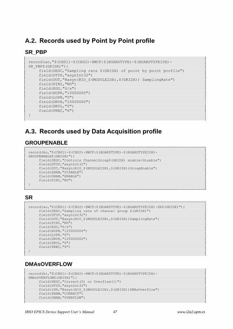
IRIO EPICS Device Support User’s Manual 47 www.i2a2.upm.es
A.2. Records used by Point by Point profile
SR_PBP
record(ao,"$(CBS1)-$(CBS2)-HWCF:$(BOARDTYPE)-$(BOARDTYPEIDX)-
SR_PBP$(GRIDX)"){
field(DESC,"Sampling rate $(GRIDX) of point by point profile")
field(DTYP,"asynInt32")
field(OUT,"@asyn(RIO_$(MODULEIDX),$(GRIDX)) SamplingRate")
field(PINI,"NO")
field(EGU,"S/s")
field(HOPR,"10000000")
field(LOPR,"0")
field(DRVH,"10000000")
field(DRVL,"0")
field(PREC,"6")
}
A.3. Records used by Data Acquisition profile
GROUPENABLE
record(bo,"$(CBS1)-$(CBS2)-HWCF:$(BOARDTYPE)-$(BOARDTYPEIDX)-
GROUPENABLE$(GRIDX)"){
field(DESC,"Controls ChannelGroup$(GRIDX) enable/disable")
field(DTYP,"asynInt32")
field(OUT,"@asyn(RIO_$(MODULEIDX),$(GRIDX))GroupEnable")
field(ZNAM,"DISABLE")
field(ONAM,"ENABLE")
field(PINI,"NO")
}
SR
record(ao,"$(CBS1)-$(CBS2)-HWCF:$(BOARDTYPE)-$(BOARDTYPEIDX)-SR$(GRIDX)"){
field(DESC,"Sampling rate of channel group $(GRIDX)")
field(DTYP,"asynInt32")
field(OUT,"@asyn(RIO_$(MODULEIDX),$(GRIDX))SamplingRate")
field(PINI,"NO")
field(EGU,"S/s")
field(HOPR,"125000000")
field(LOPR,"0")
field(DRVH,"125000000")
field(DRVL,"0")
field(PREC,"6")
}
DMAsOVERFLOW
record(bi,"$(CBS1)-$(CBS2)-HWCF:$(BOARDTYPE)-$(BOARDTYPEIDX)-
DMAsOVERFLOW$(GRIDX)"){
field(DESC,"Correct(0) or Overflow(1)")
field(DTYP,"asynInt32")
field(INP,"@asyn(RIO_$(MODULEIDX),$(GRIDX))DMAsOverflow")
field(ZNAM,"CORRECT")
field(ONAM,"OVERFLOW")

IRIO EPICS Device Support User’s Manual 48 www.i2a2.upm.es
field(PINI,"YES")
field(SCAN,".1 second")
}
DF
record(ao,"$(CBS1)-$(CBS2)-HWCF:$(BOARDTYPE)G-$(BOARDTYPEIDX)-DF$(GRIDX)"){
field(DESC,"Block Decimation factor of DMA$(GRIDX)")
field(DTYP,"asynInt32")
field(OUT,"@asyn(RIO_$(MODULEIDX),$(GRIDX))DF")
field(PINI,"NO")
field(HOPR,"100000000")
field(LOPR,"1")
field(DRVH,"100000000")
field(DRVL,"1")
field(PREC,"0")
}
CH
record(waveform,"$(CBS1)-$(CBS2)-HWCF:$(BOARDTYPE)-$(BOARDTYPEIDX)-CH$(CHIDX)"){
field(DESC,"Input waveform $(CHIDX)")
field(DTYP,"asynFloat32ArrayIn")
field(INP,"@asyn(RIO_$(MODULEIDX),$(CHIDX))CH")
field(FTVL,"FLOAT")
field(PINI,"YES")
field(NELM,"$(NSAMPLE)")
field(PREC,"6")
field(SCAN,"I/O Intr")
}
A.4. Records used by Image Data Acquisition Profile.
GROUPENABLE
record(bo,"$(CBS1)-$(CBS2)-HWCF:$(BOARDTYPE)-$(BOARDTYPEIDX)-
GROUPENABLE$(GRIDX)"){
field(DESC,"Controls ChannelGroup$(GRIDX) enable/disable")
field(DTYP,"asynInt32")
field(OUT,"@asyn(RIO_$(MODULEIDX),$(GRIDX))GroupEnable")
field(ZNAM,"DISABLE")
field(ONAM,"ENABLE")
field(PINI,"NO")
}
DMAsOVERFLOW
record(bi,"$(CBS1)-$(CBS2)-HWCF:$(BOARDTYPE)-$(BOARDTYPEIDX)-
DMAsOVERFLOW$(GRIDX)"){
field(DESC,"Correct(0) or Overflow(1)")
field(DTYP,"asynInt32")
field(INP,"@asyn(RIO_$(MODULEIDX),$(GRIDX))DMAsOverflow")
field(ZNAM,"CORRECT")
field(ONAM,"OVERFLOW")
field(PINI,"YES")
field(SCAN,".1 second")
}

IRIO EPICS Device Support User’s Manual 49 www.i2a2.upm.es
DF
record(ao,"$(CBS1)-$(CBS2)-HWCF:$(BOARDTYPE)-$(BOARDTYPEIDX)-DF$(GRIDX)"){
field(DESC,"Block Decimation factor of DMA$(GRIDX)")
field(DTYP,"asynInt32")
field(OUT,"@asyn(RIO_$(MODULEIDX),$(GRIDX))DF")
field(PINI,"NO")
field(HOPR,"100000000")
field(LOPR,"1")
field(DRVH,"100000000")
field(DRVL,"1")
field(PREC,"0")
}
SIGNALMAPPING
record(mbbo,"$(CBS1)-$(CBS2)-HWCF:$(BOARDTYPE)-$(BOARDTYPEIDX)-
SIGNALMAPPING$(GRIDX)"){
field(DESC,"Select the signal mapping $(GRIDX)")
field(DTYP,"asynInt32")
field(OUT,"@asyn(RIO_$(MODULEIDX),$(GRIDX))CLSignalMapping")
field(PINI,"NO")
field(ZRVL,"0")
field(ONVL,"1")
field(TWVL,"2")
field(ZRST,"STANDARD")
field(ONST,"BASLER10TAP")
field(TWST,"VOSKHULER10TAP")
}
CONFIGURATION
record(mbbo,"$(CBS1)-$(CBS2)-HWCF:$(BOARDTYPE)-$(BOARDTYPEIDX)-
CONFIGURATION$(GRIDX)"){
field(DESC,"0-Base,1-Medium,2-Full")
field(DTYP,"asynInt32")
field(OUT,"@asyn(RIO_$(MODULEIDX),$(GRIDX))CLConfiguration")
field(PINI,"NO")
field(ZRVL,"0")
field(ONVL,"1")
field(TWVL,"2")
field(ZRST,"BASE")
field(ONST,"MEDIUM")
field(TWST,"FULL")
}
LINESCAN
record(bo,"$(CBS1)-$(CBS2)-HWCF:$(BOARDTYPE)-$(BOARDTYPEIDX)-LINESCAN$(GRIDX)"){
field(DESC,"Set CL Line Scan $(GRIDX)")
field(DTYP,"asynInt32")
field(OUT,"@asyn(RIO_$(MODULEIDX),$(GRIDX))CLLineScan")
field(PINI,"NO")
field(ZNAM,"DISABLE")
field(ONAM,"ENABLE")
}
FVALHIGH
record(bo,"$(CBS1)-$(CBS2)-HWCF:$(BOARDTYPE)-$(BOARDTYPEIDX)-FVALHIGH$(GRIDX)"){
field(DESC,"Set CL FVAL Active High $(GRIDX)")

IRIO EPICS Device Support User’s Manual 50 www.i2a2.upm.es
field(DTYP,"asynInt32")
field(OUT,"@asyn(RIO_$(MODULEIDX),$(GRIDX))CLFVALHigh")
field(PINI,"NO")
field(ZNAM,"DISABLE")
field(ONAM,"ENABLE")
}
LVALHIGH
record(bo,"$(CBS1)-$(CBS2)-HWCF:$(BOARDTYPE)-$(BOARDTYPEIDX)-LVALHIGH$(GRIDX)"){
field(DESC,"Set CL LVAL Active High $(GRIDX)")
field(DTYP,"asynInt32")
field(OUT,"@asyn(RIO_$(MODULEIDX),$(GRIDX))CLLVALHigh")
field(PINI,"NO")
field(ZNAM,"DISABLE")
field(ONAM,"ENABLE")
}
DVALHIGH
record(bo,"$(CBS1)-$(CBS2)-HWCF:$(BOARDTYPE)-$(BOARDTYPEIDX)-DVALHIGH$(GRIDX)"){
field(DESC,"Set CL DVAL Active High $(GRIDX)")
field(DTYP,"asynInt32")
field(OUT,"@asyn(RIO_$(MODULEIDX),$(GRIDX))CLDVALHigh")
field(PINI,"NO")
field(ZNAM,"DISABLE")
field(ONAM,"ENABLE")
}
SPAREHIGH
record(bo,"$(CBS1)-$(CBS2)-HWCF:$(BOARDTYPE)-$(BOARDTYPEIDX)-SPAREHIGH$(GRIDX)"){
field(DESC,"Set CL Spare Active High $(GRIDX)")
field(DTYP,"asynInt32")
field(OUT,"@asyn(RIO_$(MODULEIDX),$(GRIDX))CLSpareHigh")
field(PINI,"NO")
field(ZNAM,"DISABLE")
field(ONAM,"ENABLE")
}
UARTRECEIVE
record(stringin,"$(CBS1)-$(CBS2)-HWCF:$(BOARDTYPE)-$(BOARDTYPEIDX)-
UARTRECEIVE$(GRIDX)"){
field(DESC,"Uart Recieve $(GRIDX)")
field(DTYP,"asynOctetRead")
field(INP,"@asyn(RIO_$(MODULEIDX),$(GRIDX))UARTReceive")
field(SCAN,"I/O Intr")
field(PINI,"YES")
}
UARTTRANSMIT
record(stringout,"$(CBS1)-$(CBS2)-HWCF:$(BOARDTYPE)-$(BOARDTYPEIDX)-
UARTTRANSMIT$(GRIDX)"){
field(DESC,"Uart Transmit $(GRIDX)")
field(DTYP,"asynOctetWrite")
field(OUT,"@asyn(RIO_$(MODULEIDX),$(GRIDX))UARTTransmit")
field(PINI,"NO")

IRIO EPICS Device Support User’s Manual 51 www.i2a2.upm.es
}
UARTBREAK
record(bi,"$(CBS1)-$(CBS2)-HWCF:$(BOARDTYPE)-$(BOARDTYPEIDX)-UARTBREAK$(GRIDX)"){
field(DESC,"Uart break indicator $(GRIDX)")
field(DTYP,"asynInt32")
field(INP,"@asyn(RIO_$(MODULEIDX),$(GRIDX))UARTBreakIndicator")
field(ZNAM,"UARTCORRECT")
field(ONAM,"UARTBREAK")
field(SCAN,".1 second")
field(PINI,"YES")
}
UARTFRAMEeRR
record(bi,"$(CBS1)-$(CBS2)-HWCF:$(BOARDTYPE)-$(BOARDTYPEIDX)-
UARTFRAMEeRR$(GRIDX)"){
field(DESC,"Frame Error $(GRIDX)")
field(DTYP,"asynInt32")
field(INP,"@asyn(RIO_$(MODULEIDX),$(GRIDX))UARTFrammingError")
field(ZNAM,"UARTCORRECT")
field(ONAM,"UARTFRAMEERROR")
field(SCAN,".1 second")
field(PINI,"YES")
}
UARTOVERRUN
record(bi,"$(CBS1)-$(CBS2)-HWCF:$(BOARDTYPE)-$(BOARDTYPEIDX)-
UARTOVERRUN$(GRIDX)"){
field(DESC,"UartCorrect(0) or UartOverrun(1)")
field(DTYP,"asynInt32")
field(INP,"@asyn(RIO_$(MODULEIDX),$(GRIDX))UARTOverrunError")
field(ZNAM,"UARTCORRECT")
field(ONAM,"UARTOVERRUN")
field(PINI,"YES")
field(SCAN,".1 second")
}
SIZEX
record(longout, "$(CBS1)-$(CBS2)-HWCF:$(BOARDTYPE)-$(BOARDTYPEIDX)-
SIZEX$(GRIDX)") {
field(DESC, "Image size in X dimension current value.")
field(DTYP, "asynInt32")
field(EGU, "pix")
field(OUT, "@asyn(RIO_$(MODULEIDX),$(GRIDX))CLSizeX")
field(FLNK, "$(CBS1)-$(CBS2)-HWCF:$(BOARDTYPE)-$(BOARDTYPEIDX)-
IMAGESIZE$(GRIDX)")
field(HOPR,"1690")
field(LOPR,"1")
field(DRVH,"1690")
field(DRVL,"1")
}

IRIO EPICS Device Support User’s Manual 52 www.i2a2.upm.es
SIZEY
record(longout, "$(CBS1)-$(CBS2)-HWCF:$(BOARDTYPE)-$(BOARDTYPEIDX)-
SIZEY$(GRIDX)") {
field(DESC, "Image size in y dimension current value.")
field(DTYP, "asynInt32")
field(EGU, "pix")
field(OUT, "@asyn(RIO_$(MODULEIDX),$(GRIDX))CLSizeY")
field(FLNK, "$(CBS1)-$(CBS2)-HWCF:$(BOARDTYPE)-$(BOARDTYPEIDX)-
IMAGESIZE$(GRIDX)")
field(HOPR,"1710")
field(LOPR,"1")
field(DRVH,"1710")
field(DRVL,"1")
}
CH
record(waveform,"$(CBS1)-$(CBS2)-HWCF:$(BOARDTYPE)-$(BOARDTYPEIDX)-CH$(CHIDX)"){
field(DESC,"Input waveform $(CHIDX)")
field(DTYP,"asynInt8ArrayIn")
field(INP,"@asyn(RIO_$(MODULEIDX),$(CHIDX))CH")
field(FTVL,"UCHAR")
field(PINI,"NO")
field(NELM,"$(NSAMPLE)")
field(SCAN,"I/O Intr")
field(FLNK, "$(CBS1)-$(CBS2)-HWCF:$(BOARDTYPE)-$(BOARDTYPEIDX)-
IMAGE$(CHIDX)")
}
IMAGE
record(subArray, "$(CBS1)-$(CBS2)-HWCF:$(BOARDTYPE)-$(BOARDTYPEIDX)-
IMAGE$(CHIDX)") {
field(DESC, "Read image.")
field(INP, "$(CBS1)-$(CBS2)-HWCF:$(BOARDTYPE)-$(BOARDTYPEIDX)-CH$(CHIDX)")
field(FTVL, "UCHAR")
field(MALM, "$(NSAMPLE)")
field(NELM, "$(NSAMPLE)")
field(PINI, "NO")
field(HOPR, "$(NSAMPLE)")
field(LOPR, "0")
}
IMAGESIZE
record(calcout, "$(CBS1)-$(CBS2)-HWCF:$(BOARDTYPE)-$(BOARDTYPEIDX)-
IMAGESIZE$(CHIDX)") {
field(DESC, "Image size")
field(EGU, "byte")
field(INPA, "$(CBS1)-$(CBS2)-HWCF:$(BOARDTYPE)-$(BOARDTYPEIDX)-
SIZEX$(CHIDX)")
field(INPB, "$(CBS1)-$(CBS2)-HWCF:$(BOARDTYPE)-$(BOARDTYPEIDX)-
SIZEY$(CHIDX)")
field(CALC, "A*B" )
field(OUT, "$(CBS1)-$(CBS2)-HWCF:$(BOARDTYPE)-$(BOARDTYPEIDX)-
IMAGE$(CHIDX).NELEM" )
field(HOPR, "$(NSAMPLE)")
field(LOPR, "0")
}

IRIO EPICS Device Support User’s Manual 53 www.i2a2.upm.es
A.5. Records for optional resources
AI
record (ai, "$(CBS1)-$(CBS2)-HWCF:$(BOARDTYPE)-$(BOARDTYPEIDX)-
AI$(CHIDX)"){
field(DESC,"Analog Input channel $(CHIDX) value")
field(DTYP,"asynFloat64")
field(INP,"@asyn(RIO_$(MODULEIDX),$(CHIDX))AI")
field(SCAN,".1 second")
field(PREC,"6")
field(PINI,"YES")
field(TSE,"-2")
}
auxAI
record (ai, "$(CBS1)-$(CBS2)-HWCF-R$(RACK)C$(CHASSIS)B$(BOARD):auxAI$(CHIDX)"){
field(DESC,"Aux Analog Input of channel $( CHIDX)")
field(DTYP,"asynInt32")
field(INP,"@asyn(RIO_$(MODULEIDX),$(CHIDX))auxAI")
field(SCAN,".1 second")
field(PREC,"0")
field(PINI,"YES")
}
AO
record (ao, "$(CBS1)-$(CBS2)-HWCF:$(BOARDTYPE)-$(BOARDTYPEIDX)-AO$(CHIDX)"){
field(DESC,"Analog Output channel $(CHIDX) value")
field(DTYP,"asynFloat64")
field(OUT,"@asyn(RIO_$(MODULEIDX),$(CHIDX))AO")
field(HOPR,"$(HOPR)")
field(LOPR,"$(LOPR)")
field(DRVH,"$(DRVH)")
field(DRVL,"$(DRVL)")
field(PREC,"6")
field(PINI,"NO")
}
AOENABLE
record(bo,"$(CBS1)-$(CBS2)-HWCF:$(BOARDTYPE)-$(BOARDTYPEIDX)-AOENABLE$(CHIDX)"){
field(DESC,"Analog Output channel $(CHIDX) enable")
field(DTYP,"asynInt32")
field(OUT,"@asyn(RIO_$(MODULEIDX),$(CHIDX))AOEnable")
field(PINI,"NO")
field(ZNAM,"DISABLE")
field(ONAM,"ENABLE")
}
auxAO
record (ao, "$(CBS1)-$(CBS2)-HWCF:$(BOARDTYPE)-$(BOARDTYPEIDX)-auxAO$(CHIDX)"){
field(DESC,"Analog Output aux channel $(CHIDX) value")
field(DTYP,"asynInt32")
field(OUT,"@asyn(RIO_$(MODULEIDX),$(CHIDX))auxAO")
field(PREC,"0")
field(HOPR,"$(HOPR)")

IRIO EPICS Device Support User’s Manual 54 www.i2a2.upm.es
field(LOPR,"$(LOPR)")
field(DRVH,"$(DRVH)")
field(DRVL,"$(DRVL)")
field(PINI,"NO")
}
DI
record (bi, "$(CBS1)-$(CBS2)-HWCF:$(BOARDTYPE)-$(BOARDTYPEIDX)-DI$(CHIDX)"){
field(DESC,"Digital Input channel $(CHIDX) value")
field(DTYP,"asynInt32")
field(INP,"@asyn(RIO_$(MODULEIDX),$(CHIDX))DI")
field(SCAN,".1 second")
field(ZNAM,"FALSE")
field(ONAM,"TRUE")
field(PINI,"YES")
field(TSE,"-2")
}
auxDI
record (bi, "$(CBS1)-$(CBS2)-HWCF:$(BOARDTYPE)-$(BOARDTYPEIDX)-auxDI$(CHIDX)"){
field(DESC,"Digital Input aux channel $(CHIDX) value")
field(DTYP,"asynInt32")
field(INP,"@asyn(RIO_$(MODULEIDX),$(CHIDX))auxDI")
field(SCAN,".1 second")
field(ZNAM,"FALSE")
field(ONAM,"TRUE")
field(PINI,"YES")
}
DO
record (bo, "$(CBS1)-$(CBS2)-HWCF:$(BOARDTYPE)-$(BOARDTYPEIDX)-DO$(CHIDX)"){
field(DESC,"Digital Output channel $(CHIDX)")
field(DTYP,"asynInt32")
field(OUT,"@asyn(RIO_$(MODULEIDX),$(CHIDX))DO")
field(ZNAM,"FALSE")
field(ONAM,"TRUE")
field(PINI,"NO")
}
auxDO
record (bo, "$(CBS1)-$(CBS2)-HWCF:$(BOARDTYPE)-$(BOARDTYPEIDX)-auxDO$(CHIDX)"){
field(DESC,"Digital Output aux channel $(CHIDX) value")
field(DTYP,"asynInt32")
field(OUT,"@asyn(RIO_$(MODULEIDX),$(CHIDX))auxDO")
field(ZNAM,"FALSE")
field(ONAM,"TRUE")
field(PINI,"NO")
}
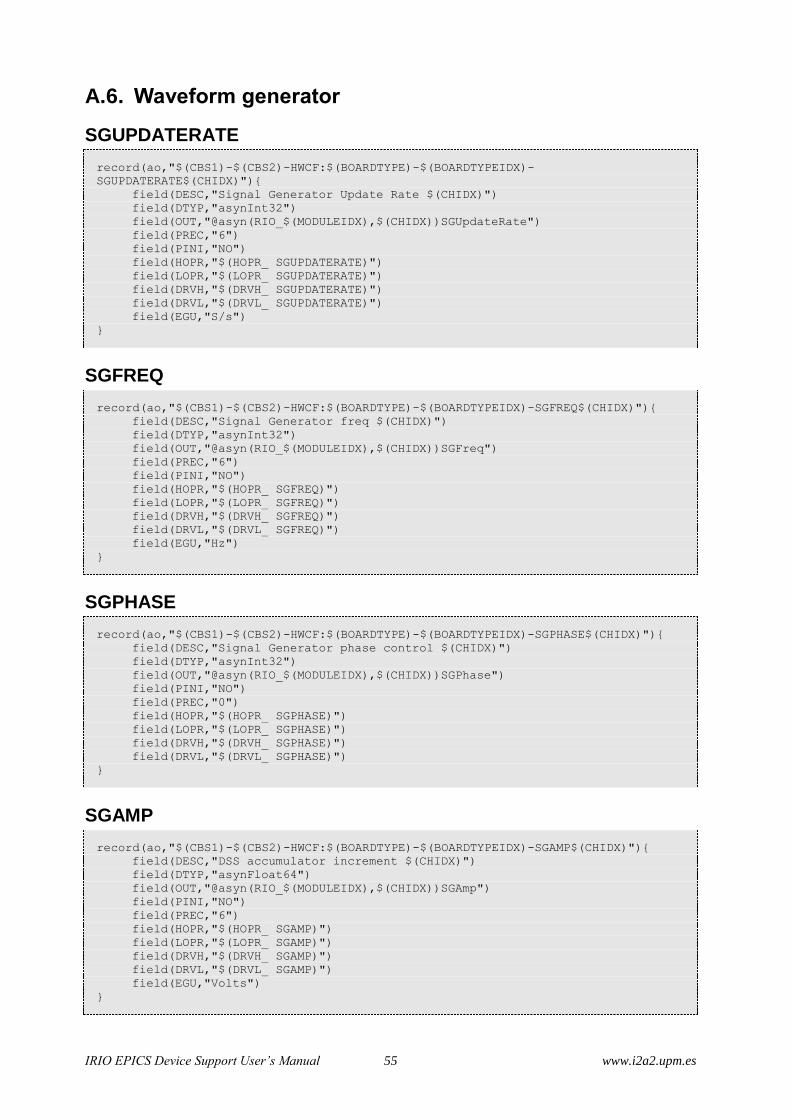
IRIO EPICS Device Support User’s Manual 55 www.i2a2.upm.es
A.6. Waveform generator
SGUPDATERATE
record(ao,"$(CBS1)-$(CBS2)-HWCF:$(BOARDTYPE)-$(BOARDTYPEIDX)-
SGUPDATERATE$(CHIDX)"){
field(DESC,"Signal Generator Update Rate $(CHIDX)")
field(DTYP,"asynInt32")
field(OUT,"@asyn(RIO_$(MODULEIDX),$(CHIDX))SGUpdateRate")
field(PREC,"6")
field(PINI,"NO")
field(HOPR,"$(HOPR_ SGUPDATERATE)")
field(LOPR,"$(LOPR_ SGUPDATERATE)")
field(DRVH,"$(DRVH_ SGUPDATERATE)")
field(DRVL,"$(DRVL_ SGUPDATERATE)")
field(EGU,"S/s")
}
SGFREQ
record(ao,"$(CBS1)-$(CBS2)-HWCF:$(BOARDTYPE)-$(BOARDTYPEIDX)-SGFREQ$(CHIDX)"){
field(DESC,"Signal Generator freq $(CHIDX)")
field(DTYP,"asynInt32")
field(OUT,"@asyn(RIO_$(MODULEIDX),$(CHIDX))SGFreq")
field(PREC,"6")
field(PINI,"NO")
field(HOPR,"$(HOPR_ SGFREQ)")
field(LOPR,"$(LOPR_ SGFREQ)")
field(DRVH,"$(DRVH_ SGFREQ)")
field(DRVL,"$(DRVL_ SGFREQ)")
field(EGU,"Hz")
}
SGPHASE
record(ao,"$(CBS1)-$(CBS2)-HWCF:$(BOARDTYPE)-$(BOARDTYPEIDX)-SGPHASE$(CHIDX)"){
field(DESC,"Signal Generator phase control $(CHIDX)")
field(DTYP,"asynInt32")
field(OUT,"@asyn(RIO_$(MODULEIDX),$(CHIDX))SGPhase")
field(PINI,"NO")
field(PREC,"0")
field(HOPR,"$(HOPR_ SGPHASE)")
field(LOPR,"$(LOPR_ SGPHASE)")
field(DRVH,"$(DRVH_ SGPHASE)")
field(DRVL,"$(DRVL_ SGPHASE)")
}
SGAMP
record(ao,"$(CBS1)-$(CBS2)-HWCF:$(BOARDTYPE)-$(BOARDTYPEIDX)-SGAMP$(CHIDX)"){
field(DESC,"DSS accumulator increment $(CHIDX)")
field(DTYP,"asynFloat64")
field(OUT,"@asyn(RIO_$(MODULEIDX),$(CHIDX))SGAmp")
field(PINI,"NO")
field(PREC,"6")
field(HOPR,"$(HOPR_ SGAMP)")
field(LOPR,"$(LOPR_ SGAMP)")
field(DRVH,"$(DRVH_ SGAMP)")
field(DRVL,"$(DRVL_ SGAMP)")
field(EGU,"Volts")
}

IRIO EPICS Device Support User’s Manual 56 www.i2a2.upm.es
SIGNALTYPE
record(mbbo,"$(CBS1)-$(CBS2)-HWCF:$(BOARDTYPE)-$(BOARDTYPEIDX)-
SGSIGNALTYPE$(CHIDX)"){
field(DESC,"Type of signal generated $(CHIDX))")
field(DTYP,"asynInt32")
field(OUT,"@asyn(RIO_$(MODULEIDX),$(CHIDX))SGSignalType")
field(PINI,"NO")
field(ZRVL,"0")
field(ONVL,"1")
field(TWVL,"2")
field(THVL,"3")
field(ZRST,"DC")
field(ONST,"SINE")
field(TWST,"SQUARE")
field(THST,"TRIANGLE")
}