ip20 isocratic pump operator's manual - dionex
TRANSCRIPT
IP20 ISOCRATIC PUMPOPERATOR’S MANUAL
©1996 Dionex Corporation
Document No. 034857Revision 03August 1996

©1996 by Dionex CorporationAll rights reserved worldwide.Printed in the United States of America.
This publication is protected by federal copyright law. No part of this publicationmay be copied or distributed, transmitted, transcribed, stored in a retrieval system,or transmitted into any human or computer language, in any form or by any means,electronic, mechanical, magnetic, manual, or otherwise, or disclosed to thirdparties without the express written permission of Dionex Corporation, 1228 TitanWay, Sunnyvale, California 94088-3603 U.S.A.
DISCLAIMER OF WARRANTY AND LIMITED WARRANTY
THIS PUBLICATION IS PROVIDED “AS IS” WITHOUT WARRANTY OFANY KIND. DIONEX CORPORATION DOES NOT WARRANT,GUARANTEE, OR MAKE ANY EXPRESS OR IMPLIEDREPRESENTATIONS REGARDING THE USE, OR THE RESULTS OF THEUSE, OF THIS PUBLICATION IN TERMS OF CORRECTNESS,ACCURACY, RELIABILITY, CURRENTNESS, OR OTHERWISE.FURTHER, DIONEX CORPORATION RESERVES THE RIGHT TO REVISETHIS PUBLICATION AND TO MAKE CHANGES FROM TIME TO TIMEIN THE CONTENT HEREINOF WITHOUT OBLIGATION OF DIONEXCORPORATION TO NOTIFY ANY PERSON OR ORGANIZATION OFSUCH REVISION OR CHANGES.
TRADEMARKS
DX LAN and SRS are trademarks of Dionex Corporation.Tefzel® is a registered trademark of E.I. du Pont de Nemours & Co.
PRINTING HISTORY
Revision 01, August 1993Revision 02, September 1993Revision 03, August 1996
Contents
1 • Introduction
1.1 Overview . . . . . . . . . . . . . . . . . . . . . . . 1-3
1.2 About This Manual . . . . . . . . . . . . . . . . . 1-4
1.2.1 Typefaces . . . . . . . . . . . . . . . . . . 1-5
1.2.2 Safety Messages and Notes . . . . . . . . 1-5
1.2.3 Symbols . . . . . . . . . . . . . . . . . . . 1-6
1.3 Related Manuals . . . . . . . . . . . . . . . . . . . 1-7
2 • Description
2.1 Front Control Panel . . . . . . . . . . . . . . . . . 2-4
2.1.1 Control Panel Keypad . . . . . . . . . . . 2-5
2.1.2 Initial Display Screens . . . . . . . . . . . 2-10
2.2 Electronics Chassis . . . . . . . . . . . . . . . . . 2-12
2.2.1 Connectors . . . . . . . . . . . . . . . . . 2-13
2.2.2 Cards . . . . . . . . . . . . . . . . . . . . 2-14
2.3 Mechanical Chassis . . . . . . . . . . . . . . . . . 2-15
2.4 Interior Components . . . . . . . . . . . . . . . . 2-15
2.4.1 Pump Heads . . . . . . . . . . . . . . . . 2-17
2.4.2 Pump Priming Block . . . . . . . . . . . . 2-18
2.4.3 Pressure Transducer . . . . . . . . . . . . 2-18
2.5 Vacuum Degas Pump Assembly (Optional) . . . . 2-19
2.6 Eluent Reservoirs . . . . . . . . . . . . . . . . . . 2-20
Doc. 034857-03 8/96 i
2.7 Rear Panel . . . . . . . . . . . . . . . . . . . . . . 2-21
2.8 Functional Description . . . . . . . . . . . . . . . 2-21
2.8.1 Operating Modes . . . . . . . . . . . . . . 2-23
2.8.2 Method Control . . . . . . . . . . . . . . 2-24
3 • Operation and Maintenance
3.1 Getting Ready to Run . . . . . . . . . . . . . . . . 3-3
3.1.1 Degas Eluents . . . . . . . . . . . . . . . 3-3
3.1.2 Filter Eluents . . . . . . . . . . . . . . . . 3-4
3.1.3 Pressurize Eluent Reservoirs . . . . . . . 3-4
3.1.4 Start-Up . . . . . . . . . . . . . . . . . . . 3-5
3.1.5 Selecting the Pressure Limits . . . . . . . 3-6
3.2 Running Under Direct Control . . . . . . . . . . . 3-7
3.3 Running Under Method Control . . . . . . . . . . 3-8
3.3.1 Creating a New Method . . . . . . . . . . 3-10
3.3.2 Running a Method . . . . . . . . . . . . . 3-12
3.3.3 Controlling the Method Clock . . . . . . 3-13
3.3.4 Editing a Method . . . . . . . . . . . . . . 3-13
3.3.5 Deleting a Method . . . . . . . . . . . . . 3-16
3.3.6 Changing the Running Method . . . . . . 3-16
3.4 Routine Maintenance . . . . . . . . . . . . . . . . 3-17
3.4.1 Daily Maintenance . . . . . . . . . . . . . 3-17
3.4.2 Periodic Maintenance . . . . . . . . . . . 3-19
3.5 Shutdown . . . . . . . . . . . . . . . . . . . . . . . 3-19
Contents
ii Doc. 034857-03 8/96

4 • Troubleshooting
4.1 Left-Right Pump Head Pressure Fluctuations . . 4-3
4.2 Pump Will Not Start . . . . . . . . . . . . . . . . 4-6
4.3 Pump Stops . . . . . . . . . . . . . . . . . . . . . 4-6
4.4 Liquid Leaks/Leak Alarm . . . . . . . . . . . . . 4-10
4.5 High-Pitched Noise From Pump Motor (orMotor Racing) . . . . . . . . . . . . . . . . . . . . 4-11
4.6 Vacuum Degas Pump Does Not Run . . . . . . . 4-12
4.7 Vacuum Degas Pump Calibration Fails . . . . . . 4-13
4.8 Vacuum Degas Pump Low Vacuum . . . . . . . . 4-14
4.9 Inoperative Relay Control Function . . . . . . . . 4-14
4.10 Poor Chromatographic Reproducibility . . . . . . 4-15
5 • Service
5.1 Cleaning the Check Valves . . . . . . . . . . . . . 5-3
5.2 Piston Seal Replacement . . . . . . . . . . . . . . 5-6
5.3 Pump Piston Replacement . . . . . . . . . . . . . 5-10
5.4 Pressure Transducer Pad and O-RingReplacement . . . . . . . . . . . . . . . . . . . . . 5-11
5.5 Pressure Transducer Waste Valve O-RingReplacement . . . . . . . . . . . . . . . . . . . . . 5-13
5.6 Changing Main Power Fuses . . . . . . . . . . . . 5-14
A • Specifications
A.1 Electrical . . . . . . . . . . . . . . . . . . . . . . . A-3
Contents
Doc. 034857-03 8/96 iii
A.2 Environmental . . . . . . . . . . . . . . . . . . . A-3
A.3 Physical . . . . . . . . . . . . . . . . . . . . . . A-3
A.4 Display and Keypad . . . . . . . . . . . . . . . . A-3
A.5 Hydraulics . . . . . . . . . . . . . . . . . . . . . A-4
A.6 Method Control . . . . . . . . . . . . . . . . . . A-5
A.7 Vacuum Degas Assembly Option . . . . . . . . . A-5
B • Installation
B.1 Facility Requirements . . . . . . . . . . . . . . . B-3
B.2 Installation Instructions . . . . . . . . . . . . . . B-4
B.2.1 Power Connection . . . . . . . . . . . . B-4
B.2.2 Electronics Chassis Connections . . . . B-5
B.2.3 DX LAN Network Connection (Optional) B-7
B.2.4 Waste Lines . . . . . . . . . . . . . . . . B-9
B.2.5 Eluent Outlet Line Connection . . . . . B-10
B.2.6 Eluent Inlet Line Connection . . . . . . B-10
B.2.7 Priming the Pump . . . . . . . . . . . . B-11
B.3 Automatic SRS Power Control . . . . . . . . . . B-15
B.4 Stacking Modules . . . . . . . . . . . . . . . . . B-17
B.5 Securing Modules (Optional) . . . . . . . . . . . B-18
B.5.1 Installing a Shoe . . . . . . . . . . . . . B-18
B.5.2 Installing a Tie . . . . . . . . . . . . . . B-19
C • User Interface
C.1 Operational Screens . . . . . . . . . . . . . . . . C-5
Contents
iv Doc. 034857-03 8/96

C.1.1 Main Screen . . . . . . . . . . . . . . . . C-5
C.1.2 Method Screen . . . . . . . . . . . . . . . C-7
C.1.3 Degas Options . . . . . . . . . . . . . . . C-9
C.1.4 Module Setup . . . . . . . . . . . . . . . C-11
C.1.5 Pump Options . . . . . . . . . . . . . . . C-12
C.1.6 Time Function In . . . . . . . . . . . . . C-13
C.2 Diagnostic Screens . . . . . . . . . . . . . . . . . C-14
C.2.1 Hexadecimal Entry Fields . . . . . . . . . C-14
C.2.2 Diagnostic Menu . . . . . . . . . . . . . . C-14
C.2.3 Power-Up Screen . . . . . . . . . . . . . C-15
C.2.4 Elapsed Time . . . . . . . . . . . . . . . . C-16
C.2.5 DSP Status . . . . . . . . . . . . . . . . . C-17
C.2.6 DX LAN Status . . . . . . . . . . . . . . C-18
C.2.7 Keyboard Test . . . . . . . . . . . . . . . C-20
C.2.8 Diagnostic Test . . . . . . . . . . . . . . . C-21
C.2.9 Pressure Statistics . . . . . . . . . . . . . C-23
C.2.10 DSP Code Version . . . . . . . . . . . . . C-24
C.3 Calibration Screens . . . . . . . . . . . . . . . . . C-25
C.3.1 Calibration Menu . . . . . . . . . . . . . C-25
C.3.2 Calibration Status . . . . . . . . . . . . . C-26
C.3.3 Leak Sensor Calibration and Status . . . C-27
C.3.4 Degas Status . . . . . . . . . . . . . . . . C-28
C.3.5 Flow Calibration . . . . . . . . . . . . . . C-29
C.3.6 Pressure Calibration . . . . . . . . . . . . C-30
C.3.7 Degas Pump Calibration . . . . . . . . . . C-34
Contents
Doc. 034857-03 8/96 v
D • TTL and Relay Control
D.1 TTL and Relay Output Operation . . . . . . . . D-4
D.2 TTL Input Operation . . . . . . . . . . . . . . . D-5
D.2.1 TTL Input Signal Modes . . . . . . . . D-5
D.3 TTL and Relay Connections . . . . . . . . . . . D-7
D.3.1 Example Connections . . . . . . . . . . D-8
Contents
vi Doc. 034857-03 8/96
1 • Introduction
1.1 Overview . . . . . . . . . . . . . . . . . . . . . . . 1-3
1.2 About This Manual . . . . . . . . . . . . . . . . . 1-4
1.2.1 Typefaces . . . . . . . . . . . . . . . . . . 1-5
1.2.2 Safety Messages and Notes . . . . . . . . 1-5
1.2.3 Symbols . . . . . . . . . . . . . . . . . . . 1-6
1.3 Related Manuals . . . . . . . . . . . . . . . . . . . 1-7
Doc. 034857-03 8/96 1-1

IP20 Isocratic Pump
1-2 Doc. 034857-03 8/96
1 • Introduction
1.1 Overview
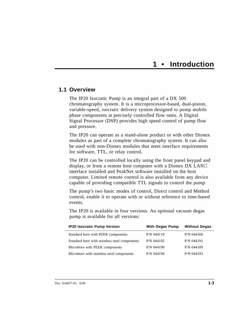
The IP20 Isocratic Pump is an integral part of a DX 500chromatography system. It is a microprocessor-based, dual-piston,variable-speed, isocratic delivery system designed to pump mobilephase components at precisely controlled flow rates. A DigitalSignal Processor (DSP) provides high speed control of pump flowand pressure.
The IP20 can operate as a stand-alone product or with other Dionexmodules as part of a complete chromatography system. It can alsobe used with non-Dionex modules that meet interface requirementsfor software, TTL, or relay control.
The IP20 can be controlled locally using the front panel keypad anddisplay, or from a remote host computer with a Dionex DX LANinterface installed and PeakNet software installed on the hostcomputer. Limited remote control is also available from any devicecapable of providing compatible TTL signals to control the pump.
The pump’s two basic modes of control, Direct control and Methodcontrol, enable it to operate with or without reference to time-basedevents.
The IP20 is available in four versions. An optional vacuum degaspump is available for all versions:
IP20 Isocratic Pump Version With Degas Pump Without Degas
Standard bore with PEEK components P/N 044119 P/N 044168
Standard bore with stainless steel components P/N 044192 P/N 044191
Microbore with PEEK components P/N 044190 P/N 044189
Microbore with stainless steel components P/N 044194 P/N 044193
Doc. 034857-03 8/96 1-3
1.2 About This Manual
Chapter 1, Introduction , introduces the product, the conventionsused in the manual, and provides safety information.
Chapter 2, Description, is a description of the physical aspects of thepump, followed by a description of the operating features.
Chapter 3, Operation and Maintenance, discusses the operatingfeatures and methods, and presents several examples of how to runmethods. Routine preventive maintenance requirements are includedin this chapter.
Chapter 4, Troubleshooting, lists possible causes of problems andprovides step-by-step procedures to isolate and eliminate their sources.
Chapter 5, Service, presents step-by-step instructions for service andparts replacement routines.
Appendix A, Specifications, contains the IP20 specifications andinstallation site specifications..
Appendix B, Installation , describes the installation steps necessaryto place the IP20 Isocratic Pump into operation.
Appendix C, User Interface, illustrates and describes all front panelmenus and screens.
Appendix D, Relay and TTL Control , describes the relay and TTLinput and output functions and provides setup examples.
IP20 Isocratic Pump
1-4 Doc. 034857-03 8/96
1.2.1 Typefaces
Typefaces are used in this manual as follows:
• Capitalized bold type indicates a front panel button:
Press Enter to begin running the method.
• Upper-case bold type indicates the name of a screen, thename of a menu, or an on-screen entry:
Go to the METHOD screen.
Move the cursor to the EDIT field.
1.2.2 Safety Messages and Notes
This instrument is designed to comply with the requirementsfor safety set forth in IEC 1010, Safety Requirements forElectrical Equipment for Measurement, Control, andLaboratory Use.
This manual contains warnings and precautionary statementsthat can prevent personal injury and/or damage to theinstrument when properly followed. Safety messages appearin bold type and are accompanied by icons.
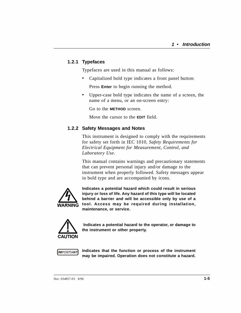
Indicates a potential hazard which could result in seriousinjury or loss of life. Any hazard of this type will be locatedbehind a barrier and will be accessible only by use of atool. Access may be required dur ing instal lat ion,maintenance, or service.
Indicates a potential hazard to the operator, or damage tothe instrument or other property.
Indicates that the function or process of the instrumentmay be impaired. Operation does not constitute a hazard.
1 • Introduction
Doc. 034857-03 8/96 1-5

Informational messages also appear throughout this manual.These are labeled NOTE and are in bold type:
NOTENOTES call attention to certain information. They alertyou to an unexpected result of an action, suggest how tooptimize the performance of the instrument, etc.
1.2.3 Symbols
The symbols below appear on the pump, or on pump labels.
Alternating current
Protective conductor terminal
Power supply is on
Power supply is off
~
IP20 Isocratic Pump
1-6 Doc. 034857-03 8/96
1.3 Related Manuals
During installation and operation of the IP20, you may need to referto one or more of the following manuals (depending on your system)for information about other modules and components included in aDX 500 system.
The following manuals are included with their respective modules orcomponents:
• PeakNet AS3500 Autosampler Editor User’s Guide (DocumentNo. 034913)
• AS40 Automated Sampler Operator’s Manual (DocumentNo. 034970)
• CD20 Conductivity Detector Operator’s Manual (DocumentNo. 034854)
• ED40 Electrochemical Detector Operator’s Manual (DocumentNo. 034855)
• E01 Eluent Organizer Installation Instructions (DocumentNo. 034582)
• Pressurizable Reservoir Installation Instructions (DocumentNo. 034851)
• LC10 Chromatography Organizer Operator’s Manual (DocumentNo. 034858)
• LC20 Chromatography Enclosure Operator’s Manual (DocumentNo. 034859)
• LC30 Chromatography Oven Operator’s Manual (DocumentNo. 034860)
The following manual is included in the IP20 Ship Kit:
• Installation of Dionex Ferrule Fittings (Document No. 034213)
1 • Introduction
Doc. 034857-03 8/96 1-7

IP20 Isocratic Pump
1-8 Doc. 034857-03 8/96
2 • Description
2.1 Front Control Panel . . . . . . . . . . . . . . . . . 2-4
2.1.1 Control Panel Keypad . . . . . . . . . . . 2-5
2.1.2 Initial Display Screens . . . . . . . . . . . 2-10
2.2 Electronics Chassis . . . . . . . . . . . . . . . . . 2-12
2.2.1 Connectors . . . . . . . . . . . . . . . . . 2-13
LC LEAK . . . . . . . . . . . . . . . . 2-13
LC COMM . . . . . . . . . . . . . . . . 2-13
LC AIR . . . . . . . . . . . . . . . . . . 2-13
TTL/Relay . . . . . . . . . . . . . . . . 2-13
2.2.2 Cards . . . . . . . . . . . . . . . . . . . . 2-14
Power Supply Card . . . . . . . . . . . 2-14
DSP (Digital Signal Processor) Card . 2-14
CPU/Relay and DX LAN Cards . . . . 2-14
2.3 Mechanical Chassis . . . . . . . . . . . . . . . . . 2-15
2.4 Interior Components . . . . . . . . . . . . . . . . 2-15
2.4.1 Pump Heads . . . . . . . . . . . . . . . . 2-17
2.4.2 Pump Priming Block . . . . . . . . . . . . 2-18
2.4.3 Pressure Transducer . . . . . . . . . . . . 2-18
2.5 Vacuum Degas Pump Assembly (Optional) . . . . 2-19
2.6 Eluent Reservoirs . . . . . . . . . . . . . . . . . . 2-20
2.7 Rear Panel . . . . . . . . . . . . . . . . . . . . . . 2-21
2.8 Functional Description . . . . . . . . . . . . . . . 2-21
2.8.1 Operating Modes . . . . . . . . . . . . . . 2-23
Local Mode . . . . . . . . . . . . . . . 2-23
Remote Mode . . . . . . . . . . . . . . 2-23
2.8.2 Method Control . . . . . . . . . . . . . . 2-24
Doc. 034857-03 8/96 2-1

IP20 Isocratic Pump
2-2 Doc. 034857-03 8/96
2 • Description
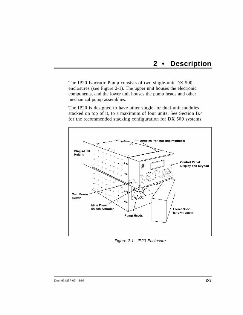
The IP20 Isocratic Pump consists of two single-unit DX 500enclosures (see Figure 2-1). The upper unit houses the electroniccomponents, and the lower unit houses the pump heads and othermechanical pump assemblies.
The IP20 is designed to have other single- or dual-unit modulesstacked on top of it, to a maximum of four units. See Section B.4for the recommended stacking configuration for DX 500 systems.
Figure 2-1. IP20 Enclosure
Doc. 034857-03 8/96 2-3
2.1 Front Control Panel
The control panel on the upper door of the IP20 enclosure containsthe liquid crystal display (LCD), the membrane keypad, and theactuator for the main power switch (see Figure 2-2). The door opensto provide access to the electronics chassis, described in Section 2.2.
Screen Contrast
Information is displayed on the LCD, also called the screen. Toadjust the screen contrast, use the knurled knob in the recess belowthe keypad (see Figure 2-2).
Tilt Panel
To maximize visibility, the front control panel can be tilted to fourdifferent positions. To tilt the panel, support the door at the left side(to prevent it from opening) and lift firmly on the tab in the middleof the recess below the keypad (see Figure 2-2). Push on the tab toreturn the panel to its vertical position.
Power Switches
The main power switch is on the bulkhead behind the upper door(see Figure 2-1). An actuator for the main power switch is on theoutside of the front door, at the lower left corner (see Figure 2-2).The actuator functions only when the door is fully closed.
When the door is open, press the main power switch on thebulkhead, instead of the actuator, to turn the module off and on.
To prevent damage to the pump circuitry and components,always wait at least 15 seconds after powering down beforeturning on the power again.
IP20 Isocratic Pump
2-4 Doc. 034857-03 8/96
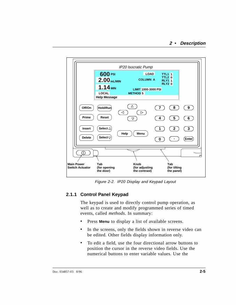
2.1.1 Control Panel Keypad
The keypad is used to directly control pump operation, aswell as to create and modify programmed series of timedevents, called methods. In summary:
• Press Menu to display a list of available screens.
• In the screens, only the fields shown in reverse video canbe edited. Other fields display information only.
• To edit a field, use the four directional arrow buttons toposition the cursor in the reverse video fields. Use thenumerical buttons to enter variable values. Use the
Help Message
PSI TTL1TTL2RLY1RLY2
METHOD
1010
COLUMN A
600 mL/MIN2.00MIN1.14
LOCAL
IP20 Isocratic Pump
Hold/Run
1
0
2 3
4 5 6
7 8 9
Enter
Off/On
Prime Reset
Insert Select
Delete SelectHelp Menu
Tab (for openin gthe door )
Tab (for tiltin g the panel)
Knob (for ad justin gthe contrast )
Main PowerSwitch Actuator
LOAD
LIMIT51000-3000 PSI
Figure 2-2. IP20 Display and Keypad Layout
2 • Description
Doc. 034857-03 8/96 2-5
Select ∆ and Select ∇ buttons to choose betweenpredetermined options. Pressing a Select button increases(or decreases) a numerical value by one, while holdingdown a Select button increases (or decreases) a numericalvalue continuously.
• Press Enter or a cursor arrow button to execute theselected value.
A high-pitched beep sounds when you press a button. Whenan error occurs, this beep is lower in frequency. The beepscan be disabled from the MODULE SET-UP screen (seeSection C.1.4).
Off/On
Turns the pump motor off and on.
In Direct control (see Section 2.8), turning on the motorcauses it to pump using the displayed eluent and flow rate.
In Method control (see Section 2.8.2), turning on the motorcauses it to pump using the eluent and flow rate for theelapsed time of the selected method, or at the initialconditions (when the method clock is at INIT).
Prime
This button is used when priming the pump heads. Primecauses the pump to run at maximum volume (2.5 mL/min,microbore; 10.0 mL/min standard bore). If the pump motor isoff when you press Prime , the pump automatically turns on.To exit priming and return to the normal flow rate, pressPrime again or press Off/On to turn the pump motor off. SeeSection B.2.7 for detailed priming instructions.
IP20 Isocratic Pump
2-6 Doc. 034857-03 8/96
Insert
Inserts a new timed step into a method. This button functionsonly when the cursor is in a TIME field in the METHOD orMETHOD extension screen.
1. Move the cursor to the TIME field and press Insert . Thenew step is added after the cursor position. Parametervalues in the new step are blank.
2. Fill in the time value and press Enter or a cursor arrowbutton. If you move the cursor to a different field beforeentering the time value, the inserted step will beincomplete and will disappear. You can insert timed stepsin any order. After you press Enter , they will beautomatically organized in correct chronological order.
Delete
Removes the value from the current entry field, allowingentry of a new value. To restore the previous value, move thecursor from the field before entering the new value.
On the METHOD screen, pressing Delete when the cursor is ina step entry field “blanks” the step parameter value. When thecursor is moved from the field, the field remains blank (theprevious value is not restored as in other screens). Blank stepfields indicate there is no change from the previous step.
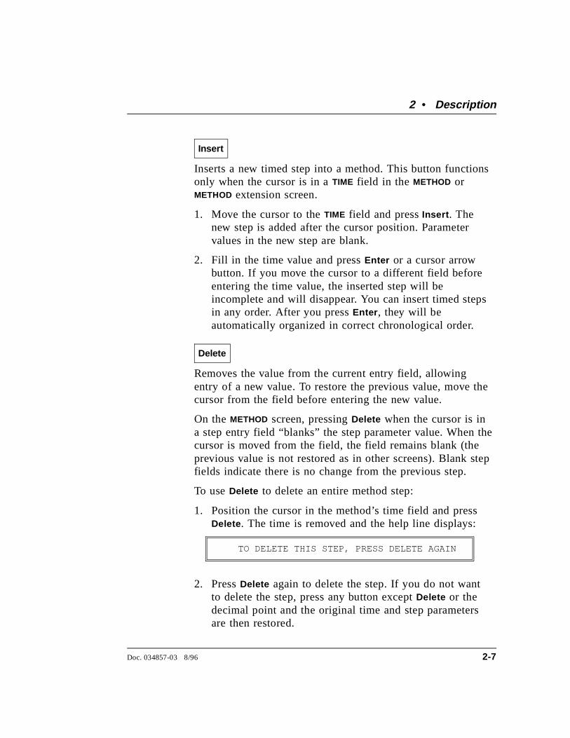
To use Delete to delete an entire method step:
1. Position the cursor in the method’s time field and pressDelete . The time is removed and the help line displays:
TO DELETE THIS STEP, PRESS DELETE AGAIN
2. Press Delete again to delete the step. If you do not wantto delete the step, press any button except Delete or thedecimal point and the original time and step parametersare then restored.
2 • Description
Doc. 034857-03 8/96 2-7
Hold/Run
Turns the method clock off (Hold ) and on (Run ). This buttonfunctions only when the pump is under Method control (seeSection 2.8.2).
When the method clock is in Hold, pressing Hold/Run , startsthe clock. The clock starts either at the initial step of a newmethod, or if resuming an interrupted method, at the time atwhich the clock was put in Hold.
When the method clock is in Run, pressing Hold/Run , stopsthe clock, thereby “holding” the method and freezing thecurrent conditions.
Reset
Changes the method clock time to INIT and causes the initialconditions specified by the method to occur. This buttonfunctions only when the pump is in Method control.
If the method is running, it continues running. If the methodis on hold, the method clock executes the initial conditionsand holds.
Select ∆ and Select ∇
When the cursor is positioned at a field that haspredetermined parameters, these buttons cycle through thechoices. In fields which have predetermined numeric values,Select ∆ increases the value by one unit and Select ∇decreases the value by one unit. Holding down the Selectbutton increases (or decreases) the value continuously. PressEnter or a cursor arrow button to execute the new value.
IP20 Isocratic Pump
2-8 Doc. 034857-03 8/96
←, ↑, →, and ↓
The four cursor directional buttons move the cursor, in thedirection of the arrow, to the next entry field. If there is nochangeable field in that direction, the cursor movesdiagonally or remains where it is.
In most cases, after entering or selecting a new value in anentry field, pressing an arrow button saves and/or executesthe new value. This performs the same function as pressingEnter .
Pressing Enter is still required in the following situations:
• to exeucte a test from the DIAGNOSTIC TEST screen
• after entering a method number in the SAVE TO and RUNfields on the METHOD screen
• to execute a calibration procedure
• to go to a screen after highlighting it on a menu
Help
Displays a help screen specific to the current entry field.
Menu
Displays one of three menus, depending on the current screen:
• From any operational screen, pressing Menu displays theMENU of SCREENS .
• From any diagnostic screen, pressing Menu displays theDIAGNOSTIC MENU. Pressing Menu again returns you to theMENU of SCREENS .
• From any calibration screen, pressing Menu displays theCALIBRATION MENU . Pressing Menu again returns you tothe DIAGNOSTIC MENU and then to the MENU of SCREENS.
See Figure C-1 for the IP20 screens and menu structure.
2 • Description
Doc. 034857-03 8/96 2-9

Numeric Buttons
Enters numeric values into the current entry field. Thenumeric buttons are 0 through 9 and the decimal.
Enter
Saves and/or executes changes made in entry fields. Afterpressing Enter , the cursor moves back to the left margin ofthe same field. It does not automatically move to the nextentry field. In menu screens, pressing Enter opens thehighlighted screen.
In the METHOD screen, pressing Enter saves entries to an editcopy only. To save the editing changes to a permanentmethod, move the cursor to the SAVE TO field, enter themethod number, and press Enter .
2.1.2 Initial Display Screens
When the pump is powered-up, the POWER-UP screen displaysbriefly (see Figure 2-3) and a series of diagnostic tests arerun. If the pump passes all the tests, the MAIN screen displays(see Figure 2-5). If one of the diagnostic tests fails, theDIAGNOSTIC TEST screen displays instead of the MAIN screen.See Section C.2.8 if this occurs.
Help Message
IP20 ISOCRATIC PUMP
PUMP HEAD VOLUME 100 uLMODULEWARE REVn.nn
BIOS REVnnnnnnDX LAN ID#n.nn
Figure 2-3. Power-Up Screen
IP20 Isocratic Pump
2-10 Doc. 034857-03 8/96
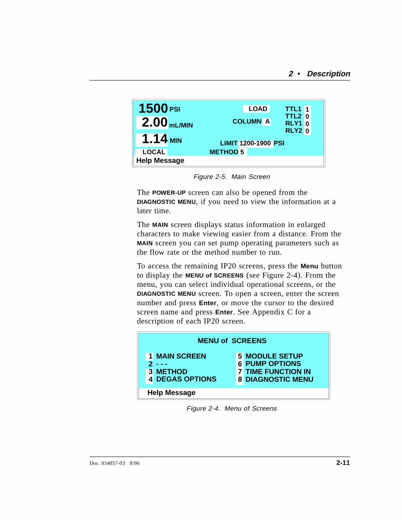
The POWER-UP screen can also be opened from theDIAGNOSTIC MENU, if you need to view the information at alater time.
The MAIN screen displays status information in enlargedcharacters to make viewing easier from a distance. From theMAIN screen you can set pump operating parameters such asthe flow rate or the method number to run.
To access the remaining IP20 screens, press the Menu buttonto display the MENU of SCREENS (see Figure 2-4). From themenu, you can select individual operational screens, or theDIAGNOSTIC MENU screen. To open a screen, enter the screennumber and press Enter , or move the cursor to the desiredscreen name and press Enter . See Appendix C for adescription of each IP20 screen.
Help Message
PSI TTL1TTL2RLY1RLY2
METHOD
1000
COLUMN A
1500 mL/MIN2.00MIN1.14
LOCAL
LOAD
LIMIT51200-1900 PSI
Figure 2-5. Main Screen
Help Message
MAIN SCREEN
METHOD- - -
MODULE SETUPPUMP OPTIONSTIME FUNCTION INDIAGNOSTIC MENU
1234
5678
MENU of SCREENS
DEGAS OPTIONS
Figure 2-4. Menu of Screens
2 • Description
Doc. 034857-03 8/96 2-11

2.2 Electronics Chassis
The electronics chassis is located behind the upper door of the IP20enclosure. The chassis includes several electronic cards (printedcircuit boards) that are used to control the IP20. Connectors on thecards also allow communication between the IP20 and other DX 500modules. Figure 2-6 shows the electronics components with theupper door open. To open the door, pull on the tab located to theright of the main power actuator (see Figure 2-2).
Do not remove any of the electronics cards from the pump.There are no user-serviceable components on the cards.If servicing is required, it must be performed by qualifiedpersonnel and appropriate electrostatic discharge (ESD)handling procedures must be followed.
Figure 2-6. Electronics Chassis (Located behind pump upper door)
IP20 Isocratic Pump
2-12 Doc. 034857-03 8/96

2.2.1 Connectors
LC LEAK
The leak control cable from the LC20 ChromatographyEnclosure or the LC10 Chromatography Organizer connectsto the LC LEAK connector in slot 1. When a leak occurs in theLC10 or LC20, it is reported to the IP20.
The LC30 Chromatography Oven does not connect to theIP20 LC LEAK connector, because it has its own internal leakcontrol electronics.
LC COMM
The LC30 Chromatography Oven’s RJ-11 serial cableconnects to the LC COMM connector in slot 1. Whenconnected, the LC30 can be remotely controlled by thePeakNet workstation.
LC AIR
The cable from the air solenoid valves on the LC10, LC20, orLC30 connects to the LC AIR connector in slot 1. Whenconnected, the IP20 can electrically actuate the solenoidvalves which control the position of the injection valve in theLC10, LC20, and LC30.
If an optional column switching valve (P/N 044858) isinstalled in the LC20 or LC30, a Y-extension cable (P/N047746) connects the LC AIR connector to the air solenoidvalves that control the injection and column switching valves
Use the MAIN or METHOD screen to select the injection valveposition and the optional column switching valve position.
TTL/Relay
A strip of eight relay and TTL connectors is located in slot 4.These connectors interface with Dionex and non-Dionexmodules for relay and TTL control of the pump. Appendix D
2 • Description
Doc. 034857-03 8/96 2-13
describes the relay and TTL functions and the connectionsbetween the IP20 and other modules.
2.2.2 Cards
Power Supply Card
Provides power for the pump electronics.
DSP (Digital Signal Processor) Card
Contains the digital circuitry to interface to the CPU.
CPU/Relay and DX LAN Cards
The CPU logic and Relay I/O cards occupy slot 5 in the cardcage. The Relay I/O card rides piggyback on the CPU cardand extends over the front of slot 4. The card is short enoughto allow the optional DX LAN pump interface card(P/N 044195) to mount behind it in slot 4. The DX LANinterface card is required for communication between theIP20 and PeakNet Software.
Control Moduleware and BIOS for the IP20 reside on theCPU card. A 60-pin ribbon cable links the CPU logic to thedisplay and keypad.
The CPU logic monitors the internal power supply outputs,and reports the status on the multicolored LED at the bottomof slot 4.
• Green indicates normal operation.
• Red indicates a power fault. The module will enter itsdiagnostic state and inhibit all other controls until thefault is corrected. If this occurs, turn the power off for afew seconds and then turn it back on. If the problempersists, contact Dionex.
IP20 Isocratic Pump
2-14 Doc. 034857-03 8/96
2.3 Mechanical Chassis
The mechanical chassis is housed in a pull-out drawer locatedbehind the lower door of the IP20 enclosure. The front of the chassiscontains the interior components described in Section 2.4. Othermechanical assemblies are located inside the chassis drawer. Thedrawer should be pulled out only for service procedures. For routineoperation, push in the drawer and tighten the lock located on thelower right corner of the chassis.
Observe the warning label on the inside of the lower door.The arrows on the label indicate moving mechanical partsthat present pinch hazards when the pump is on and themechanical drawer is open. Do not operate the pump withthe mechanical chassis drawer pulled out.
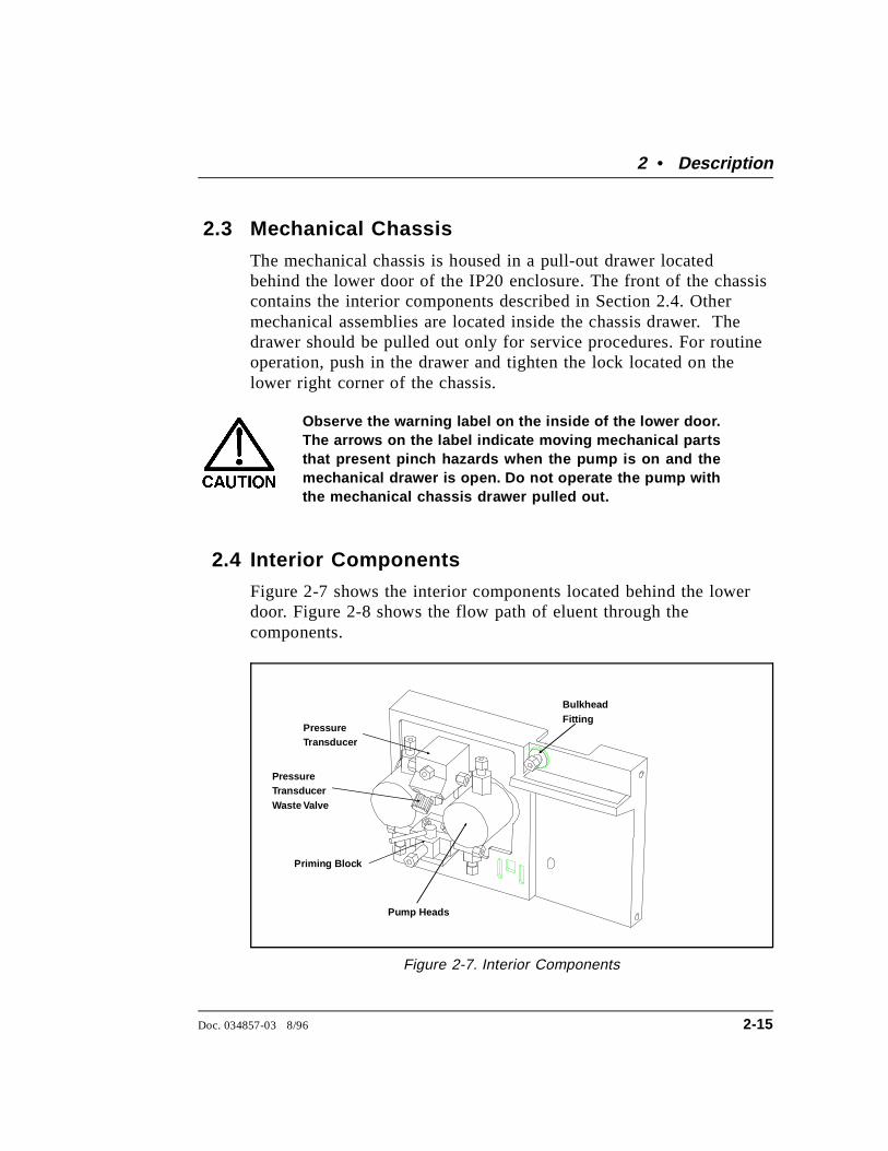
2.4 Interior Components
Figure 2-7 shows the interior components located behind the lowerdoor. Figure 2-8 shows the flow path of eluent through thecomponents.
Bulkhead Fitting
Priming Block
Pump Heads
PressureTransducer
PressureTransducerWaste Valve
Figure 2-7. Interior Components
2 • Description
Doc. 034857-03 8/96 2-15

2.4.1 Pump Heads
There are two IP20 pump head configurations: standard boreand microbore. The table below summarizes the features ofeach type and the operating conditions for each configuration.
Pump HeadType
PistonVolume
Flow Rate(mL/min)*
ColumnSizes
MaximumOperating Pressure
StandardBore
100 µL 0.04 – 10.0 4-mm and9-mm ID
35 MPa(5000 psi)
Microbore 25 µL 0.01 – 2.50 1-mm –4-mm ID
35 MPa(5000 psi)
*Flow rates are adjustable in increments of 0.01 mL/min.
Eluent In
Pump Heads
Priming Block
Pressure Transducer
To Column
Outlet CheckValve
Inlet CheckValve
Figure 2-8. Eluent Flow Schematic
IP20 Isocratic Pump
2-16 Doc. 034857-03 8/96
NOTEAlthough there is some overlap in flow rates between thetwo pump versions, continuous operation of the microborepump heads at flow rates above 2.0 mL/min will decreaseseal and pump life. For the best extended operation at2.0 mL/min or above, replace the microbore pump headswith standard bore pump heads. Contact Dionex forinformation about converting to a different pump headversion.
See Figures 5-1 and 5-2 for an illustration of the pump headsand interconnecting lines.
2 • Description
Doc. 034857-03 8/96 2-17

2.4.2 Pump Priming Block
The priming block “tee” directs the flow of eluent from thebulkhead fitting or vacuum degas chamber into the pumpheads. The priming block is also used for rapid removal of airfrom the system.
Refer to Section B.2.7 for instructions on priming the pumpheads.
2.4.3 Pressure Transducer
From the priming block, the liquid stream is directed to theinlet check valves on the pump heads, through the pumpheads, and finally through the outlet check valves to thepressure transducer.
Flow paths from the outlet check valves on the pump headsare combined in the pressure transducer. The pressuretransducer measures the system pressure at this point. Theinteractive constant-flow/constant-pressure control program onthe DSP precisely controls the pump motor speed to assure flowrate accuracy. A Kel-F disk and PTFE O-ring isolate the eluentfrom the metal pressure transducer.
The pressure transducer includes a pressure waste valve foruse when priming the pump. Open this valve for a fewseconds to relieve the pressure and force air out of thesystem, then close it to resume analysis (see Figure 2-7).
Flow output from the pressure transducer is directed from thepump and throughout the chromatography system (injectionvalve, column, detector).
See Section B.2.5 in Appendix B for outlet line connections.Refer also to the manual for the module being used forspecific interconnect information.
IP20 Isocratic Pump
2-18 Doc. 034857-03 8/96
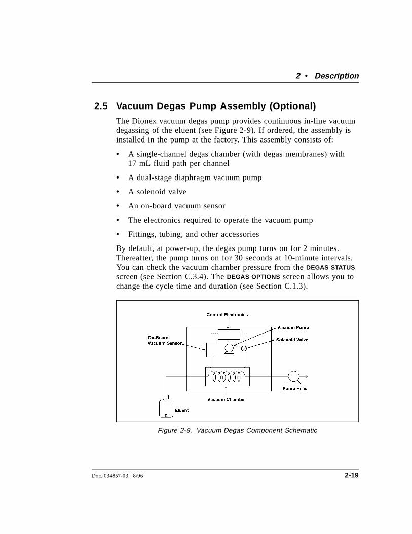
2.5 Vacuum Degas Pump Assembly (Optional)
The Dionex vacuum degas pump provides continuous in-line vacuumdegassing of the eluent (see Figure 2-9). If ordered, the assembly isinstalled in the pump at the factory. This assembly consists of:
• A single-channel degas chamber (with degas membranes) with17 mL fluid path per channel
• A dual-stage diaphragm vacuum pump
• A solenoid valve
• An on-board vacuum sensor
• The electronics required to operate the vacuum pump
• Fittings, tubing, and other accessories
By default, at power-up, the degas pump turns on for 2 minutes.Thereafter, the pump turns on for 30 seconds at 10-minute intervals.You can check the vacuum chamber pressure from the DEGAS STATUS
screen (see Section C.3.4). The DEGAS OPTIONS screen allows you tochange the cycle time and duration (see Section C.1.3).
Figure 2-9. Vacuum Degas Component Schematic
2 • Description
Doc. 034857-03 8/96 2-19
All components of the vacuum degas assembly are made of inertmaterials or corrosion-resistant materials. However, Dionexrecommends that you thoroughly flush any chemicals out of thetubing with deionized water before shutdown to avoid crystallizationin the membrane pores.
2.6 Eluent Reservoirs
Dionex strongly recommends degassing all eluents and storing themin reservoirs pressurized with helium. This helps prevent bubbles(resulting from eluent outgassing) from forming in the eluentproportioning valves, pump heads, and the detector cell. Degassedeluents and pressurized reservoirs are especially important whencombining aqueous and non-aqueous components (e.g., water andacetonitrile). Pressurizable reservoirs allow eluents to be storedunder a specific atmosphere.
The following reservoirs are available from Dionex:
• 1-liter glass reservoirs with shatterproof plastic coating(P/N 044126)
• 2-liter glass reservoirs with shatterproof plastic coating(P/N 044127)
• 1-liter plastic reservoirs (P/N 044128)
• 2-liter plastic reservoirs (P/N 044129)
Do not use the 2-liter plastic reservoir (P/N 044129) foroff-line vacuum degassing of eluents. Repeated use for thispurpose will cause the reservoir to collapse.
Refer to the Pressurizable Reservoir Installation Instructions forinstallation details.
Two optional E01 Eluent Organizers (P/N 044125) can fit on top ofthe system enclosure. Each organizer can accommodate up to tworeservoirs.
IP20 Isocratic Pump
2-20 Doc. 034857-03 8/96
2.7 Rear Panel
The rear panel contains the main power receptacle with fuses, and aBNC connector for interfacing the IP20 with the PeakNetworkstation via the optional DX LAN. The rear panel is illustratedin Figure B-1 in Appendix B.
2.8 Functional Description
There are three ways to operate the IP20 pump:
• In Local mode, you use the front control panel buttons andscreens to set operating parameters. See Section 2.8.1 for adescription of Local mode.
• In Remote mode, you use PeakNet to send operating commandsfrom the host computer via the DX LAN. See Section 2.8.1 for adescription of Remote mode.
• With TTL input, a controlling device, such as an integrator oranother DX 500 module, sends TTL signals to the pump. TheTTL input signals can be used to turn the pump motor off andon, set the method clock to hold or run, or increase and decreasethe method number. All other IP20 operating parameters must beset locally with the control panel. See Appendix D for adescription of TTL control.
To select the operating mode:
1. Go to either the MAIN or DETAIL screen. The operating mode fielddisplays either LOCAL or REMOTE (see Figure 2-10).
2. To change the mode, move the cursor to this field; press Select ∆or Select ∇ to toggle to the desired mode and press Enter or acursor arrow button. (For TTL input control, set the IP20 toLocal mode.)
2 • Description
Doc. 034857-03 8/96 2-21
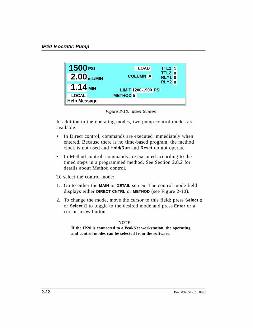
In addition to the operating modes, two pump control modes areavailable:
• In Direct control, commands are executed immediately whenentered. Because there is no time-based program, the methodclock is not used and Hold/Run and Reset do not operate.
• In Method control, commands are executed according to thetimed steps in a programmed method. See Section 2.8.2 fordetails about Method control.
To select the control mode:
1. Go to either the MAIN or DETAIL screen. The control mode fielddisplays either DIRECT CNTRL or METHOD (see Figure 2-10).
2. To change the mode, move the cursor to this field; press Select ∆or Select ∇ to toggle to the desired mode and press Enter or acursor arrow button.
NOTEIf the IP20 is connected to a PeakNet workstation, the operatingand control modes can be selected from the software.
Help Message
PSI TTL1TTL2RLY1RLY2
METHOD
1000
COLUMN A
1500 mL/MIN2.00MIN1.14
LOCAL
LOAD
LIMIT51200-1900 PSI
Figure 2-10. Main Screen
IP20 Isocratic Pump
2-22 Doc. 034857-03 8/96
Both Direct and Method control are available in either the Localmode or the Remote mode. The combination of available operatingmodes and control modes maximizes the flexibility of pumpoperation. The table below summarizes the different operating andcontrol mode configurations:
Operating/Control Mode Pump Operation
Local/Direct Commands entered from the control panel andexecuted immediately after being entered
Local/Method Commands entered from the control panel andexecuted by running a programmed method
Remote/Direct Commands sent from PeakNet and executedimmediately when received
Remote/Method Commands sent from PeakNet and executed byrunning a programmed method
2.8.1 Operating Modes
Local Mode
When the pump is powered up, it is in Local mode (seeFigure 2-10). In Local mode, the pump accepts operatingcommands from two sources:
• Direct input from the front panel keypad
• TTL inputs from a remote controller, such as an integratoror another DX 500 module
Remote Mode
In Remote mode, the pump accepts operating commands fromthe PeakNet workstation, which are sent via the DX LAN.
Remote control can be set to either normal Remote or LockedRemote:
• In normal Remote mode, all front panel buttons functionexcept Hold/Run . Operating parameters can be changed,
2 • Description
Doc. 034857-03 8/96 2-23
providing they do not interfere with a method while it isrunning in remote control.
• In the Locked Remote mode, all operating changes fromthe IP20 front panel are disabled. Locked Remote modecan be selected only from PeakNet. It can be clearedeither from PeakNet or by powering down the IP20. TheIP20 always powers up in the Local mode.
If the pump is running a method when you change to theRemote mode, the computer will not interrupt the methodunless you send an abort command from the computer.
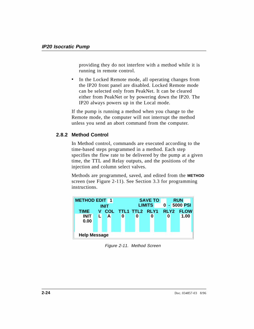
2.8.2 Method Control
In Method control, commands are executed according to thetime-based steps programmed in a method. Each stepspecifies the flow rate to be delivered by the pump at a giventime, the TTL and Relay outputs, and the positions of theinjection and column select valves.
Methods are programmed, saved, and edited from the METHOD
screen (see Figure 2-11). See Section 3.3 for programminginstructions.
Help Message
COL FLOWA
METHOD EDITLIMITS 0 - 5000SAVE TO RUN
TIMEL 1.00
INIT
0.00
PSIV RLY1TTL1 TTL2 RLY2
0 0 0 0
1
INIT
Figure 2-11. Method Screen
IP20 Isocratic Pump
2-24 Doc. 034857-03 8/96
The following summarizes basic information about usingmethods.
• The pump can run under method control while you areentering or editing any method, even the one that iscurrently running.
• When saving changes to the currently running method, orswitching to a different method, the method clockcontinues running unaffected. Only those parameterchanges which affect the method after the current timewill be implemented in the current run.
• The IP20 can store up to 100 separate methods(0 through 99) in memory. The actual number, whichdepends on the size of each method and the amount ofavailable memory, is typically less than this.
• Methods are retained in memory even after the pump ispowered down.
• Each method can have a maximum of 50 time-based steps.Step 1 always starts at INIT (initial conditions). Step 2always starts at TIME = 0.0.
• After PeakNet downloads a method to the IP20, thecomputer sends a command to activate the method numberand execute the INIT conditions step. If a method isrunning when the computer activates the new method, theold method is interrupted and the method clock is reset tothe INIT conditions.
2 • Description
Doc. 034857-03 8/96 2-25

IP20 Isocratic Pump
2-26 Doc. 034857-03 8/96
3 • Operation and Maintenance
3.1 Getting Ready to Run . . . . . . . . . . . . . . . . 3-3
3.1.1 Degas Eluents . . . . . . . . . . . . . . . 3-3
Degassing Eluents Manually . . . . . . 3-3
3.1.2 Filter Eluents . . . . . . . . . . . . . . . . 3-4
3.1.3 Pressurize Eluent Reservoirs . . . . . . . 3-4
3.1.4 Start-Up . . . . . . . . . . . . . . . . . . . 3-5
3.1.5 Selecting the Pressure Limits . . . . . . . 3-6
3.2 Running Under Direct Control . . . . . . . . . . . 3-7
3.3 Running Under Method Control . . . . . . . . . . 3-8
3.3.1 Creating a New Method . . . . . . . . . . 3-10
Example: Creating a Method . . . . . . 3-11
3.3.2 Running a Method . . . . . . . . . . . . . 3-12
3.3.3 Controlling the Method Clock . . . . . . 3-13
3.3.4 Editing a Method . . . . . . . . . . . . . . 3-13
Example: Editing a Running Method . 3-15
3.3.5 Deleting a Method . . . . . . . . . . . . . 3-16
3.3.6 Changing the Running Method . . . . . . 3-16
3.4 Routine Maintenance . . . . . . . . . . . . . . . . 3-17
3.4.1 Daily Maintenance . . . . . . . . . . . . . 3-17
3.4.2 Periodic Maintenance . . . . . . . . . . . 3-19
3.5 Shutdown . . . . . . . . . . . . . . . . . . . . . . . 3-19
Doc. 034857-03 7/96 3-1
IP20 Isocratic Pump
3-2 Doc. 034857-03 7/96
3 • Operation and Maintenance
3.1 Getting Ready to Run
3.1.1 Degas Eluents
Dionex strongly recommends degassing all eluents andstoring them in reservoirs pressurized with filtered inert gas(see Section 3.1.3). This helps prevent bubbles (resultingfrom eluent outgassing) from forming in the pump heads andthe detector cell. Degassed eluents and pressurized reservoirsare especially important when combining aqueous andnon-aqueous components (e.g., water and acetonitrile).
The IP20 with the optional vacuum degas pump assemblycontinuously degasses eluents and reagents.
If the IP20 is not equipped with the vacuum degas assembly,manually vacuum-degas eluents daily, as described below,and store them in pressurized reservoirs.
Degassing Eluents Manually
1. Prepare the eluent required for your application. Pour itinto a vacuum flask and attach the flask to a vacuumpump or water aspirator.
2. Vacuum-degas the eluent for 5 minutes in addition toshaking or sonication.
3. Remove the flask from the vacuum. Do not allow waterto flow from the aspirator back into the flask.
4. Pour the degassed eluent into a pressurizable reservoir. Becareful not to shake the eluent.
5. Install end-line filters and pressurize the reservoirs (seeSections 3.1.2 and 3.1.3).
Doc. 034857-03 7/96 3-3
3.1.2 Filter Eluents
Always filter eluents with a 0.45 µ filter before use to removesmall particulates that may contaminate the pump checkvalves and cause erratic flow rates or loss of prime. Foradditional protection, end-line filters (P/N 045987) aresupplied in the pressurizable reservoir ship kits for filteringduring operation.
Install an end-line filter on the end of the eluent line insidethe reservoir. To prevent air from being drawn through theline, make sure that the end of the filter reaches the bottomof the eluent reservoir.
3.1.3 Pressurize Eluent Reservoirs
Pressurize eluent reservoirs with filtered inert gas (preferablyhelium). If helium is not available, use argon or nitrogen.Refer to the Pressurizable Reservoir Installation Instructionsfor details.
1. Verify that a regulator (P/N 046594) is installed on thegas supply line to the reservoirs.
2. Turn on the gas supply and adjust the pressure to 55 KPa(8 psi).
Never pressurize the reservoirs above 69 KPa (10 psi).
IP20 Isocratic Pump
3-4 Doc. 034857-03 7/96
3.1.4 Start-Up
1. Turn on the pump power. The POWER-UP screen displays(see Figure 2-3) briefly and a series of diagnostics tests isrun. If the tests run successfully, the MAIN screen displays(see Figure 2-5) after a few seconds. If one or more of thetests fails, the DIAGNOSTIC TEST screen displays instead ofthe MAIN screen. See Section C.2.8 if this occurs.
At power up, the injection valve is initialized to the Loadposition and the column switching valve is initialized toits saved position.
2. Press Off/On to start the pump flow.
3. Check the pressure reading on the MAIN screen. The IP20display updates the pressure readout once per pistonstroke. The reading from one stroke to the next should bewithin 3% of the total pressure reading.
A variation of more than 3% may indicate that the pumpis not primed. The pump can lose prime if it has beenshut down for an extended period of time. (Overnightshutdown generally does not cause loss of prime.) Referto Section B.2.7 for priming instructions, or seeSection 4.1 for other conditions which can cause thepump to lose prime.
NOTEWait at least 10 minutes (up to 30 minutes for low flowrates in a standard bore pump) after starting thepump or changing the flow rate before beginning ananalysis. This allows the pump’s real-time electronicpulse damping circuitry to stabilize the flow rate.
3 • Operation and Maintenance
Doc. 034857-03 7/96 3-5
3.1.5 Selecting the Pressure Limits
The high and low pressure limits automatically stop the pumpin the event of a system malfunction (e.g., overpressurizingbecause of a blockage, or low pressure caused by a leakdownstream from the pump).
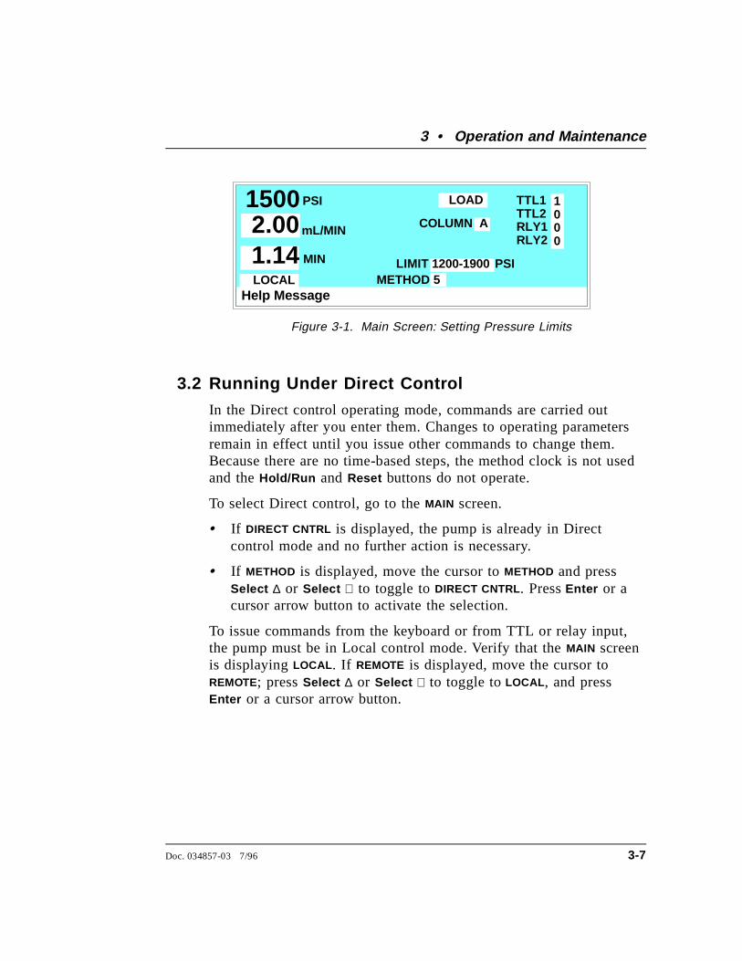
When running under Direct control, enter the pressure limitsfrom the MAIN screen (see Figure 3-1).
When running under Method control, enter the limits fromthe METHOD screen as a part of each method. The limits are setin the INIT step and remain unchanged throughout the analysis.When a limit trip stops the pump, the method clock immediatelystops and goes to Hold. The current status of the method thatwas running at the time is displayed on the front panel.
To select the limits:
1. Go to the MAIN or METHOD screen and move the cursor tothe LIMIT field.
2. Enter a low pressure limit that is 2 to 2.75 MPa(300-400 psi) below the normal system operatingpressure, as indicated by the pressure display on the frontpanel. The low pressure limit is activated after 13 pumppiston strokes of fluid is pumped through. Thirteen pistonstrokes equals 1.3 mL for the standard bore IP20 or0.325 mL for the microbore IP20.
3. Enter a high pressure limit that is 2 to 2.75 MPa(300-400 psi) above the maximum normal systemoperating pressure. The pump is equipped with a pressurelimiter that prevents operation above 35 MPa (5076 psi).
IP20 Isocratic Pump
3-6 Doc. 034857-03 7/96
3.2 Running Under Direct Control
In the Direct control operating mode, commands are carried outimmediately after you enter them. Changes to operating parametersremain in effect until you issue other commands to change them.Because there are no time-based steps, the method clock is not usedand the Hold/Run and Reset buttons do not operate.
To select Direct control, go to the MAIN screen.
• If DIRECT CNTRL is displayed, the pump is already in Directcontrol mode and no further action is necessary.
• If METHOD is displayed, move the cursor to METHOD and pressSelect ∆ or Select ∇ to toggle to DIRECT CNTRL. Press Enter or acursor arrow button to activate the selection.
To issue commands from the keyboard or from TTL or relay input,the pump must be in Local control mode. Verify that the MAIN screenis displaying LOCAL . If REMOTE is displayed, move the cursor toREMOTE; press Select ∆ or Select ∇ to toggle to LOCAL , and pressEnter or a cursor arrow button.
Help Message
PSI TTL1TTL2RLY1RLY2
METHOD
1000
COLUMN A
1500 mL/MIN2.00MIN1.14
LOCAL
LOAD
LIMIT51200-1900 PSI
Figure 3-1. Main Screen: Setting Pressure Limits
3 • Operation and Maintenance
Doc. 034857-03 7/96 3-7
3.3 Running Under Method Control
In the Method control operating mode, a series of programmedtimed events, known as a method, controls the IP20. Methods areretained in memory even after the pump power has been turned off.
This section provides general instructions on how to create, edit, andrun methods. Examples for creating a method and modifying anexisting method are also included.
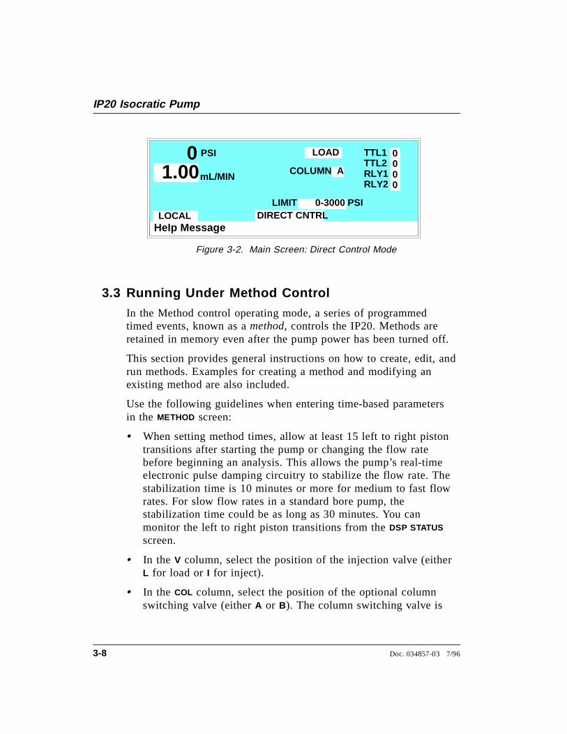
Use the following guidelines when entering time-based parametersin the METHOD screen:
• When setting method times, allow at least 15 left to right pistontransitions after starting the pump or changing the flow ratebefore beginning an analysis. This allows the pump’s real-timeelectronic pulse damping circuitry to stabilize the flow rate. Thestabilization time is 10 minutes or more for medium to fast flowrates. For slow flow rates in a standard bore pump, thestabilization time could be as long as 30 minutes. You canmonitor the left to right piston transitions from the DSP STATUS
screen.
• In the V column, select the position of the injection valve (eitherL for load or I for inject).
• In the COL column, select the position of the optional columnswitching valve (either A or B). The column switching valve is
Help Message
PSI TTL1TTL2RLY1RLY2
LOCAL
0000
COLUMN A
0 mL/MIN1.00
LOAD
LIMIT 0-3000 PSIDIRECT CNTRL
Figure 3-2. Main Screen: Direct Control Mode
IP20 Isocratic Pump
3-8 Doc. 034857-03 7/96
an option installed in the LC20 Chromatography Enclosure, orthe LC30 Chromatography Oven.
• The TTL and RLY columns control functions in external devicesthat are connected to the IP20. To turn on a TTL or relayfunction, set the value to 1. To turn off a function, set the valueto 0. For example, if TTL1 is connected to the load function onan autosampler, setting TTL1 to 1, sends the signal to theautosampler to start the load cycle. See Appendix D for detailsabout TTL and relay control.
• In the FLOW column, enter the pump flow rate. Flow rates areadjustable in increments of 0.01 mL/min. See Section 2.4.1 forthe available flow rate ranges. They vary, depending on the sizeof the pump head.
Continuous operation of the microbore pump heads at flowrates above 2.0 mL/min will decrease seal and pump life.For the best extended operation at 2.0 mL/min or above,replace the microbore pump heads with standard borepump heads.
• The TIME field is the only field in a method step that must havean entered value. A blank field in any other step indicates nochange from the value set in the previous step.
• If a method contains more steps than can be displayed on onescreen, they are scrolled off the screen. A small arrow down (∨)next to the time entry at the bottom of the screen indicates thereare additional steps below. A small arrow up (^) adjacent to thetop time entry indicates there are additional steps above. Movethe cursor to the bottom or top of the screen and then move onemore line to view the additional steps.
3 • Operation and Maintenance
Doc. 034857-03 7/96 3-9
3.3.1 Creating a New Method
You can create a new method when the method clock is ineither Hold or Run .
1. Go to the MAIN screen.
2. Check that the pump is set to LOCAL . If REMOTE iscurrently set, move the cursor to the field; press Select ∆or Select ∇ to toggle to LOCAL , and press Enter or a cursorarrow button.
3. Go to the METHOD screen.
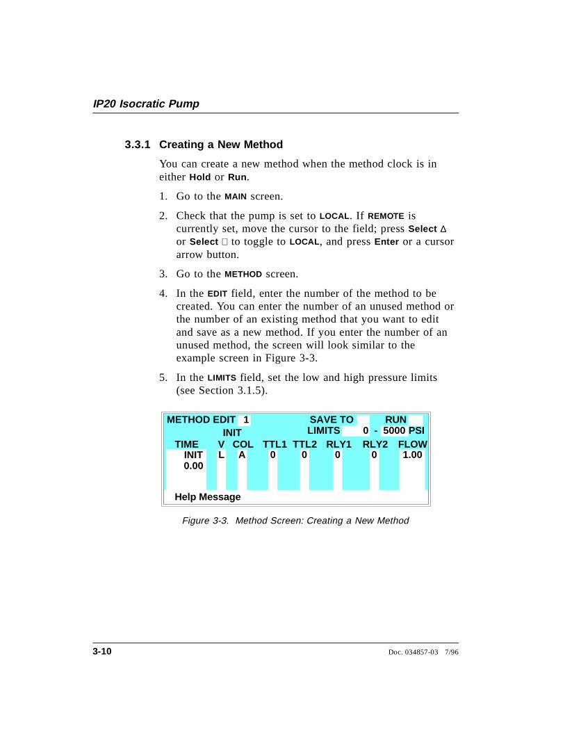
4. In the EDIT field, enter the number of the method to becreated. You can enter the number of an unused method orthe number of an existing method that you want to editand save as a new method. If you enter the number of anunused method, the screen will look similar to theexample screen in Figure 3-3.
5. In the LIMITS field, set the low and high pressure limits(see Section 3.1.5).
Help Message
COL FLOWA
METHOD EDITLIMITS 0 - 5000SAVE TO RUN
TIMEL 1.00
INIT
0.00
PSIV RLY1TTL1 TTL2 RLY2
0 0 0 0
1
INIT
Figure 3-3. Method Screen: Creating a New Method
IP20 Isocratic Pump
3-10 Doc. 034857-03 7/96
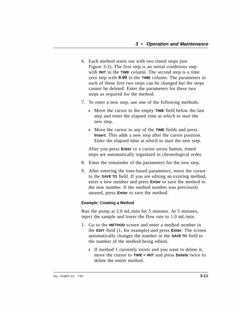
6. Each method starts out with two timed steps (seeFigure 3-3). The first step is an initial conditions stepwith INIT in the TIME column. The second step is a timezero step with 0.00 in the TIME column. The parameters ineach of these first two steps can be changed but the stepscannot be deleted. Enter the parameters for these twosteps as required for the method.
7. To enter a new step, use one of the following methods:
• Move the cursor to the empty TIME field below the laststep and enter the elapsed time at which to start thenew step.
• Move the cursor to any of the TIME fields and pressInsert . This adds a new step after the cursor position.Enter the elapsed time at which to start the new step.
After you press Enter or a cursor arrow button, timedsteps are automatically organized in chronological order.
8. Enter the remainder of the parameters for the new step.
9. After entering the time-based parameters, move the cursorto the SAVE TO field. If you are editing an existing method,enter a new number and press Enter to save the method tothe new number. If the method number was previouslyunused, press Enter to save the method.
Example: Creating a Method
Run the pump at 2.0 mL/min for 5 minutes. At 5 minutes,inject the sample and lower the flow rate to 1.0 mL/min.
1. Go to the METHOD screen and enter a method number inthe EDIT field (1, for example) and press Enter . The screenautomatically changes the number in the SAVE TO field tothe number of the method being edited.
• If method 1 currently exists and you want to delete it,move the cursor to TIME = INIT and press Delete twice todelete the entire method.
3 • Operation and Maintenance
Doc. 034857-03 7/96 3-11
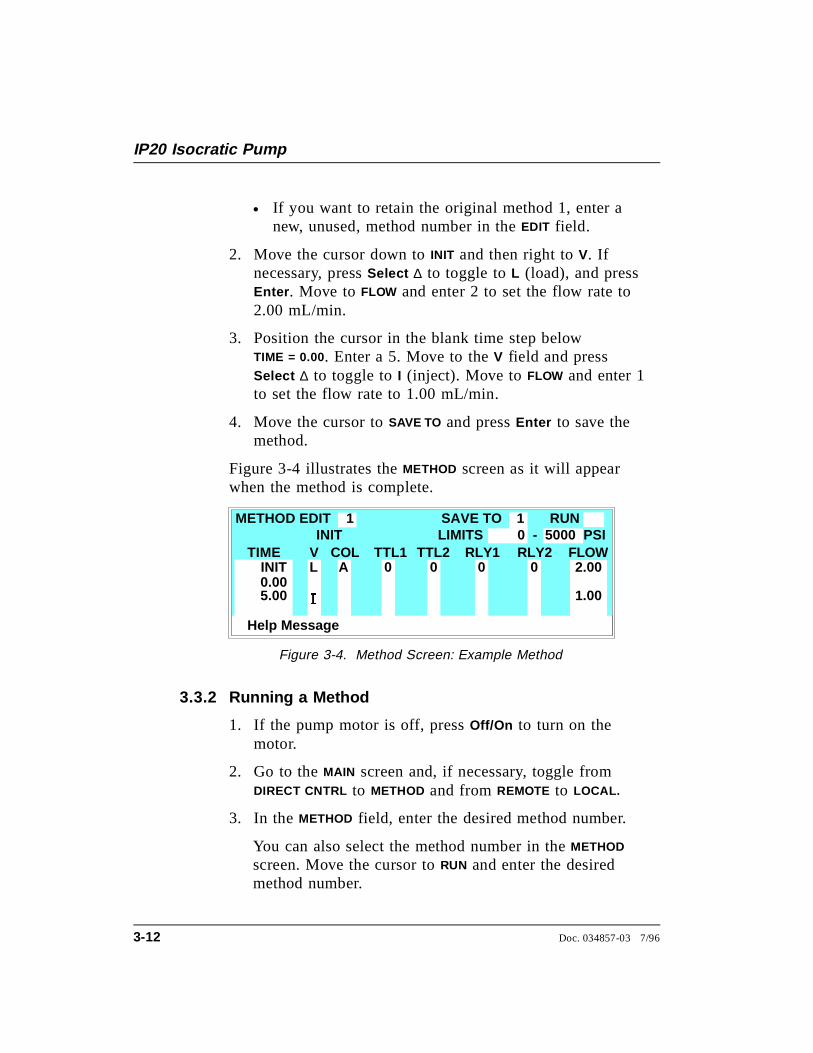
• If you want to retain the original method 1, enter anew, unused, method number in the EDIT field.
2. Move the cursor down to INIT and then right to V. Ifnecessary, press Select ∆ to toggle to L (load), and pressEnter . Move to FLOW and enter 2 to set the flow rate to2.00 mL/min.
3. Position the cursor in the blank time step belowTIME = 0.00. Enter a 5. Move to the V field and pressSelect ∆ to toggle to I (inject). Move to FLOW and enter 1to set the flow rate to 1.00 mL/min.
4. Move the cursor to SAVE TO and press Enter to save themethod.
Figure 3-4 illustrates the METHOD screen as it will appearwhen the method is complete.
3.3.2 Running a Method
1. If the pump motor is off, press Off/On to turn on themotor.
2. Go to the MAIN screen and, if necessary, toggle fromDIRECT CNTRL to METHOD and from REMOTE to LOCAL.
3. In the METHOD field, enter the desired method number.
You can also select the method number in the METHOD
screen. Move the cursor to RUN and enter the desiredmethod number.
Help Message
COL FLOWA
METHOD EDITLIMITS 0 - 5000SAVE TO RUN
TIMEL 2.00
INIT
0.00
PSIV RLY1TTL1 TTL2 RLY2
0 0 0 0
1
INIT
1
5.00 , 1.00
Figure 3-4. Method Screen: Example Method
IP20 Isocratic Pump
3-12 Doc. 034857-03 7/96
• If the method clock is already running when you enterthe method number, the method starts immediately.
• If the clock is in Hold, press Hold/Run to start themethod.
4. The elapsed time on the method clock when the methodbegins determines where (at what step and parameters)the method begins running:
• If the method clock is at INIT or time zero, the methodbegins running using the initial condition parameters.
• If the method clock is greater than zero, the methodbegins running using the parameters specified in thestep for that elapsed time. Press Reset to start themethod at the initial conditions.
3.3.3 Controlling the Method Clock
The Hold/Run button, the Reset button, and the MIN fields inthe MAIN screen control the method clock:
• To start and stop the method clock, press Hold/Run .
• To reset the clock to INIT, press Reset .
• To set the clock to a specific elapsed time, enter the timeinto the MIN field in the MAIN screen. The method will start(or continue) running using the method parametersspecified for that time.
3.3.4 Editing a Method
After entering a method, you can modify it by changing,adding, or deleting steps and/or parameters. These changescan be made when the method clock is stopped, or while it isrunning. If the method you are editing is currently running,the changes are stored in memory and implemented when yousave the method.
3 • Operation and Maintenance
Doc. 034857-03 7/96 3-13
NOTEAfter you save changes, there is no way to recall theoriginal method. Therefore, if you plan to makeexperimental changes to a method but want to retain theoriginal method in its unmodified form, save the modifiedmethod to a different method number.
Use the following basic steps to edit a method:
1. Go to the METHOD screen. In the EDIT field, enter thenumber of the method to be modified.
2. Make changes as needed:
• To change a field’s value, position the cursor in thefield and enter the new value. This automaticallydeletes the previous value.
• To add a method step, move the cursor to any of theTIME fields and press Insert , or move the cursor to theempty TIME field below the last step and enter theelapsed time at which to start the new step. After youpress Enter or a cursor arrow button, the new step isautomatically moved to the correct chronologicalposition. Continue entering parameters for the newstep.
• To delete a method step, move the cursor to the stepto be deleted and press Delete twice.
3. When changes are complete, move the cursor to theSAVE TO field. Press Enter to save the changes to thecurrent method, or enter a new method number and pressEnter.
If you save changes to the currently running method, theyare immediately incorporated in the run and executed atthe programmed time. If, however, a change is made to anevent that has already been executed, it cannot beincorporated as part of the current run. To run thechanged version of the method, press Reset to restart themethod at the INITial conditions.
IP20 Isocratic Pump
3-14 Doc. 034857-03 7/96

Example: Editing a Running Method
This example describes how to make the following changes tothe example created in Section 3.3.1:
• In the INIT step, set TTL1 to 1, which starts the load cycleon an autosampler connected to the TTL1 output.
• In the TIME = 0.00 step, set TTL1 back to 0.
• Add a step at TIME = 6.00 to switch the injection valveback to the load position.
Figure 3-5 illustrates the METHOD screen as it will appearwhen editing is complete.
This example assumes that the example method created inSection 3.3.1 is currently running.
1. Go to the METHOD screen and enter the method number (1in the example) in the EDIT field. Press Enter .
2. Move the cursor to the TTL1 field in the INIT step. Enter a1.
3. Move the cursor to the TTL1 field in the TIME = 0.00 step.Enter a 0.
4. Move the cursor to the empty time step after TIME = 5.00.Enter a 6. Move to the V field and press Select ∆ to toggleto L (load).
5. Move the cursor to the SAVE TO field and press Enter .
Help Message
COL FLOWA
METHOD EDITLIMITS 0 - 5000SAVE TO RUN
TIMEL 2.00
2.18 MIN
0.00
PSIV RLY1TTL1 TTL2 RLY2
1 0 0 0
1
INIT
1
5.00 , 1.006.00 L
0
1
Figure 3-5. Method Screen: Editing a Running Method
3 • Operation and Maintenance
Doc. 034857-03 7/96 3-15
6. Check the status of the method clock. The elapsed time isdisplayed below METHOD EDIT in the METHOD screen andin the MAIN screen.
• If the elapsed time is less than 6 minutes, the injectionvalve will be switched back to the load positionaccording to the changes made to the method.
• If the elapsed time is greater than 6 minutes, none ofthe changes will be incorporated into this run. Toimplement the changes, press Reset to set the methodclock back to the INITial conditions.
3.3.5 Deleting a Method
To delete an entire method, move the cursor on the METHOD
screen to the INIT step, then press Delete twice.
3.3.6 Changing the Running Method
To change from the method currently running to a differentmethod, enter the new method number in the RUN field on theMETHOD screen, and press Enter . The new method beginsrunning using the parameters specified in the step for thecurrent elapsed time. Press Reset to start the method at theINITial conditions.
IP20 Isocratic Pump
3-16 Doc. 034857-03 7/96
3.4 Routine Maintenance
3.4.1 Daily Maintenance
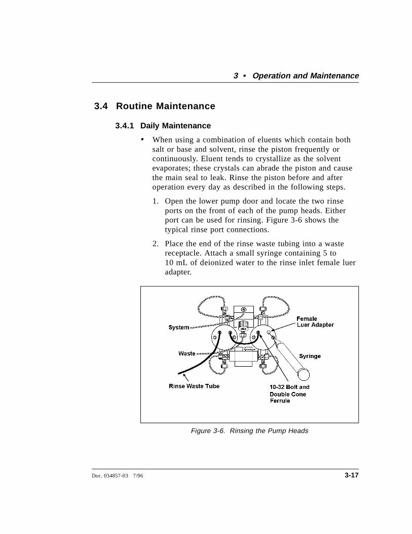
• When using a combination of eluents which contain bothsalt or base and solvent, rinse the piston frequently orcontinuously. Eluent tends to crystallize as the solventevaporates; these crystals can abrade the piston and causethe main seal to leak. Rinse the piston before and afteroperation every day as described in the following steps.
1. Open the lower pump door and locate the two rinseports on the front of each of the pump heads. Eitherport can be used for rinsing. Figure 3-6 shows thetypical rinse port connections.
2. Place the end of the rinse waste tubing into a wastereceptacle. Attach a small syringe containing 5 to10 mL of deionized water to the rinse inlet female lueradapter.
Figure 3-6. Rinsing the Pump Heads
3 • Operation and Maintenance
Doc. 034857-03 7/96 3-17
3. Inject deionized water into the fitting to rinse thepump heads. The water flows through the first head,then through the short connecting tubing to rinse thesecond head, and out to waste.
4. Dispose of the waste water and close the door to themechanical chassis.
• All components of the vacuum degas assembly are madeof inert materials or corrosion-resistant materials. Dionexrecommends that you thoroughly flush any chemicals outof the chambers and tubing with deionized water aftereach use to avoid crystallization in the membrane pores.
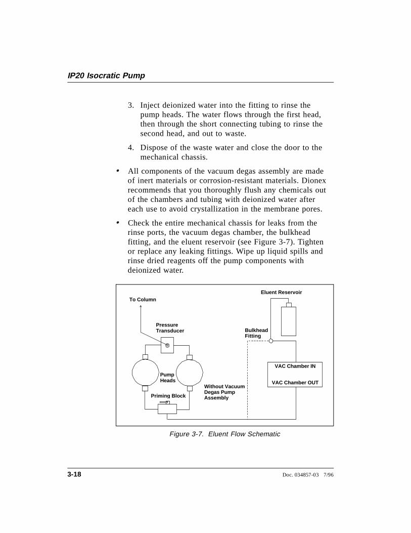
• Check the entire mechanical chassis for leaks from therinse ports, the vacuum degas chamber, the bulkheadfitting, and the eluent reservoir (see Figure 3-7). Tightenor replace any leaking fittings. Wipe up liquid spills andrinse dried reagents off the pump components withdeionized water.
Eluent Reservoir
Pump Heads
Primin g Block
Pressure Transducer
To Column
VAC Chamber IN
VAC Chamber OUT
Bulkhead Fittin g
Without VacuumDegas PumpAssembl y
Figure 3-7. Eluent Flow Schematic
IP20 Isocratic Pump
3-18 Doc. 034857-03 7/96

3.4.2 Periodic Maintenance
Replace both the primary and back-up piston seals in eachpump head every 6 months, or sooner if you suspect a leak,operate the pump continuously, or routinely run at highpressure or high flow rates (see Section 5.2). A drop ofsolvent trapped in the end of the drain tubes is normal, butsolvent flowing from the tubing indicates a leak.
Normal friction and wear will gradually cause small leaksaround the piston seals. If the piston seals are not replacedregularly, these leaks can eventually damage the pumpmechanism, impair operation, and irreversibly damage thepump.
3.5 Shutdown
• Stop the pump by turning off the main power either on the IP20or at the power source. Omit this step if you are going tomaintain a continuous rinse on the pump heads.
• Rinse the pump pistons before and after daily operation toprevent build-up of salt crystals or other contaminants that candamage the piston seal (see Section 3.4.1).
• If the pump will not be used for three days or more, flush thesystem with deionized water to prevent contaminants frombuilding up. Or, if this is not possible, maintain a continuousrinse through the system until you resume normal operation.Select a flow rate of 0.04 mL/min for standard pump heads or0.01 mL/min for microbore pump heads.
• If the shutdown is for more than three days, reduce the pressureon the eluent reservoir(s) to approximately 21 KPa (3 psi).
3 • Operation and Maintenance
Doc. 034857-03 7/96 3-19

IP20 Isocratic Pump
3-20 Doc. 034857-03 7/96
4 • Troubleshooting
4.1 Left-Right Pump Head Pressure Fluctuations . . . 4-3
4.2 Pump Will Not Start . . . . . . . . . . . . . . . . 4-6
4.3 Pump Stops . . . . . . . . . . . . . . . . . . . . . 4-6
4.4 Liquid Leaks/Leak Alarm . . . . . . . . . . . . . . 4-10
4.5 High-Pitched Noise From Pump Motor (orMotor Racing) . . . . . . . . . . . . . . . . . . . . 4-11
4.6 Vacuum Degas Pump Does Not Run . . . . . . . 4-12
4.7 Vacuum Degas Pump Calibration Fails . . . . . . 4-13
4.8 Vacuum Degas Pump Low Vacuum . . . . . . . . 4-14
4.9 Inoperative Relay Control Function . . . . . . . . 4-14
4.10 Poor Chromatographic Reproducibility . . . . . . 4-15
Doc. 034857-03 8/96 4-1

IP20 Isocratic Pump
4-2 Doc. 034857-03 8/96
4 • Troubleshooting
This chapter is a guide to troubleshooting problems that may occurwhile operating the IP20 Isocratic Pump. To use this guide, turn tothe section that best describes the operating problem. There, youwill find the possible causes of the problem listed in order ofprobability, along with the recommended courses of action. Foradditional help, refer to Appendix C for instructions on running theIP20 diagnostics program. If you cannot eliminate a problem onyour own, notify Dionex.
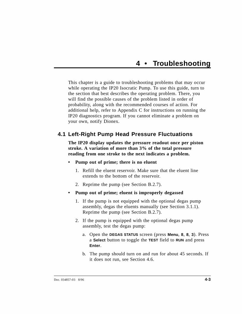
4.1 Left-Right Pump Head Pressure Fluctuations
The IP20 display updates the pressure readout once per pistonstroke. A variation of more than 3% of the total pressurereading from one stroke to the next indicates a problem.
• Pump out of prime; there is no eluent
1. Refill the eluent reservoir. Make sure that the eluent lineextends to the bottom of the reservoir.
2. Reprime the pump (see Section B.2.7).
• Pump out of prime; eluent is improperly degassed
1. If the pump is not equipped with the optional degas pumpassembly, degas the eluents manually (see Section 3.1.1).Reprime the pump (see Section B.2.7).
2. If the pump is equipped with the optional degas pumpassembly, test the degas pump:
a. Open the DEGAS STATUS screen (press Menu , 8, 8, 3). Pressa Select button to toggle the TEST field to RUN and pressEnter .
b. The pump should turn on and run for about 45 seconds. Ifit does not run, see Section 4.6.
Doc. 034857-03 8/96 4-3

• Pump is out of prime; liquid line leak
Check for liquid leaks (see Section 4.4). Tighten fittings orreplace lines.
• Pump is out of prime; eluent reservoir is not pressurized
1. Pressurize the reservoir (see Section 3.1.3).
2. Reprime the pump (see Section B.2.7).
• Pump is out of prime; end-line filter is dirty or clogged
1. Replace the filter (P/N 045987).
2. Reprime the pump (see Section B.2.7).
• Pump is out of prime; air leaks or blockages in inlet tubing
1. Check and replace any damaged fitting or tubing.
2. Reprime the pump (see Section B.2.7).
• Priming did not eliminate excessive pressure fluctuations;dirty or defective piston seal or check valves.
1. Select the DSP STATUS screen from the DIAGNOSTIC MENU andcompare PISTON PRESSURIZATION POINT readings; the defectivepiston is the one with the higher pressurization point number.Normally, the left and right values are approximately equal(within 3%).
2. Follow these steps to isolate the cause:
a. Check for leaks from the piston rinse tubing. If there areno leaks, clean and/or replace the check valves (seeSection 5.1). Dirty check valves are caused by impuritiesin the eluent. To prevent this in future, filter your eluentand install an end-line filter (P/N 045987) on the end ofthe eluent line in the reservoir.
b. If the piston rinse tubing leaks, or if you replace thecheck valves but the problem persists, replace the pistonseals (see Section 5.2).
IP20 Isocratic Pump
4-4 Doc. 034857-03 8/96
c. Turn off the main power switch.
d. Using a 7-mm open-end wrench or your fingers,loosen the mechanical chassis drawer lock on thelower right side of the chassis (see the label on theinside of the lower door). Pull the drawer out aboutfour inches.
e. Turn on the main power switch and press Off/On toturn on the pump. Observe the pistons; both pistonsshould move. If they do not, the rocker arm spring isbroken and must be replaced. Notify Dionex.
Observe the warning label on the inside of the lower door.The arrows on the label indicate moving mechanical partsthat present pinch hazards when the pump is on and themechanical drawer is open. Do not touch any parts withinthe mechanical chassis while the pump is on.
f. If the pistons move, then one or both may be brokenor scratched. In this case, turn off the main powerswitch, remove the pump head and examine the piston.If it is broken, replace it (see Section 5.3).
g. If a piston moves slightly and then breaks contact withthe rocker arm follower, replace the piston seal (seeSection 5.2); it is too tight. (The rocker arm followeris the cylinder that holds the piston in place as itmoves in and out of the pump head assembly.)
h. Push the mechanical chassis drawer back in place,making sure the cables are not pinched. Retighten thedrawer lock. Turn on the main power switch.
4 • Troubleshooting
Doc. 034857-03 8/96 4-5
4.2 Pump Will Not Start
• Flow rate is set to zero
Reset the flow rate (see Section 2.4.1).
• While being primed, pump starts briefly, then stops becauseof high pressure limit
1. Check the high pressure limit setting (see Section 3.1.5).
2. Replace any crimped or blocked tubing downstream from thepressure transducer. If there is none, go on to Step 2.
3. Open the pressure transducer waste valve by turning the knobcounterclockwise about two turns (see Figure 2-7). Check thepressure reading; if it is above 97 KPa (14 psi), recalibratethe pressure transducer (see Section C.3.6).
4. Select a lower flow rate or, if it is safe to do so, increase thehigh pressure limit.
4.3 Pump Stops
• Method or other remote input instructed the pump to stop
Check the display screen for error messages. If none aredisplayed, the pump was probably instructed to stop by themethod, computer, or other remote signal source.
• Electrical cables improperly installed
1. Place the pump in LOCAL mode, DIRECT CONTROL. PressOff/On to start the pump.
2. If a non-zero flow rate is displayed and the Off/On LEDindicates on, but the pump is not running, verify that theelectrical cables in the mechanical chassis are properlyinstalled.
a. Turn off the main power switch.
IP20 Isocratic Pump
4-6 Doc. 034857-03 8/96
b. Using a 7-mm open-end wrench or your fingers, loosenthe mechanical chassis drawer lock on the lower right sideof the chassis (see the label on the inside of the lowerdoor). Pull the drawer out a few inches.
c. Check that all cables are seated properly in the connectorson the distribution card located on the top of themechanical chassis.
d. Push the mechanical chassis drawer back in place, makingsure the cables are not pinched. Retighten the drawerlock. Turn on the main power switch.
• Low pressure limit was tripped. The following message isdisplayed:
Low Pressure Limit Violation
1. Check the low pressure limit setting (see Section 3.1.5).
2. Verify that eluent is present. If the eluent reservoir is empty,refill it. Prime the pump (see Section B.2.7) before resumingoperation.
3. Make sure the waste valve on the pressure transducer isclosed (i.e., turn the knob on the pressure transducer housingclockwise as shown in Figure 2-7).
Overtightening the pressure transducer waste valve maydamage the valve and the pressure transducer housing.
4. Make sure there are no liquid leaks in the flow system.
4 • Troubleshooting
Doc. 034857-03 8/96 4-7
5. Place the pump in LOCAL mode, DIRECT CONTROL. PressOff/On to start the pump. Verify that the pistons are movingand that you can hear the pump. If you hear the pump but thepistons are not moving, a mechanism on the pump is brokenand must be replaced. Contact Dionex. If there is no soundfrom the pump, check the LED on the CPU card inside thedoor to the electronics chassis (see Figure 2-6). A red LEDindicates a defective power supply. The power supply(P/N 046440) must be replaced. Contact Dionex.
6. With the pump running, go to the DSP STATUS screen (pressMenu , 8, 3) and note whether the left-right pressure varies bymore than 3% between strokes. If it does, refer to Section4.1. If it does not, either increase the flow rate or reduce thelow pressure limit setting and continue operation.
• High pressure limit was tripped. The following message isdisplayed:
High Pressure Limit Violation
1. Check the high pressure limit setting (see Section 3.1.5).
2. Replace any crimped or blocked tubing downstream from thepressure transducer. If there is none, go on to Step 2.
3. Open the pressure transducer waste valve by turning the knobcounterclockwise about two turns as shown in Figure 2-7.Check the pressure reading; if it is above 97 KPa (14 psi),recalibrate the pressure transducer (see Section C.3.6).
4. Select a lower flow rate or, if it is safe to do so, increase thehigh pressure limit.
• An error message beginning with “DSP” displays:
There are several messages related to Digital Signal Processor(DSP) errors; for example, “DSP communication fails” and “DSPdoes not acknowledge.” These are all treated similarly:
IP20 Isocratic Pump
4-8 Doc. 034857-03 8/96

1. Turn off the main power switch. Verify that the DSP card ispresent and is properly installed in slot 1 of the electronicschassis card cage (see Figure 2-6).
2. Turn on the pump main power. The DSP error messageshould not reappear; if it does, notify Dionex. The powersupply (P/N 046440), DSP card (P/N 045369), or CPU card(P/N 046340) may need replacing.
Do not remove any of the electronic cards from the detector.There are no user-serviceable components on the cards.If servicing is required, it must be performed by qualifiedpersonnel and appropriate electrostatic discharge (ESD)handling procedures must be followed.
• The following error message displays:
Motor Drive Fails
If the pump motor is in a runaway condition, the motorautomatically shuts off and the above error message is displayed.Contact Dionex.
• The following error message displays:
Encoder Index Not Found
1. Turn off the main power switch. Verify that the cablesconnected to the DSP card in the electronics chassis (seeFigure 2-6) are seated properly.
2. Turn on the main power switch. The error message shouldnot reappear; if it does, notify Dionex.
4 • Troubleshooting
Doc. 034857-03 8/96 4-9
4.4 Liquid Leaks/Leak Alarm
• Leaks from the front or rear of the piston head indicate adefective piston seal
Replace the piston seal (see Section 5.2). If liquid is leakingfrom the rear of the piston, also replace the piston backup seal(see Section 5.2).
• Leaks from any connection between the eluent reservoir andthe pump heads indicates an eluent leak (see Figure 3-7)
Tighten the fitting connections just enough to stop the leak.
• Pressure transducer leaks
Inspect the pressure transducer. If the waste valve is the sourceof the leak, replace the waste valve O-ring (see Section 5.5). Ifthe leak is from the rear of the transducer, replace the pressurepad and O-ring (see Section 5.4).
• Priming valve leaks
Tighten any leaking fittings just enough to stop the leak. Also,verify that the small lever on the priming block is pushed all theway to the right (see Figure B-5). If this does not stop the leak,the priming block assembly (P/N 045730) must be replaced.Contact Dionex for assistance.
• Interior mechanical chassis leaks
1. Turn off the main power switch.
2. Using a 7-mm open-end wrench or your fingers, loosen themechanical chassis drawer lock on the lower right side of thechassis (see the label on the inside of the lower door). Pullthe drawer out a few inches.
3. Inspect for leaks and tighten any leaking fittings just enoughto stop the leak. If the leak is caused by a damaged part,replace the part.
4. Push the mechanical chassis drawer back in place, makingsure the cables are not pinched. Retighten the drawer lock.
IP20 Isocratic Pump
4-10 Doc. 034857-03 8/96
4.5 High-Pitched Noise From Pump Motor (or MotorRacing)
• DSP (digital signal processing) card current limit has beenexceeded.
A built-in current limiter on the card protects the motor andmotor drive. Check the three small LEDs in the upper left cornerof the DSP card bulkhead. (The DSP card is located in slot 1 ofthe electronics chassis card cage). If the bottom LED is flashingin time with the pump strokes, the current limiter is beingactivated.
As the pump motor ages, it becomes less efficient and thecurrent limit is activated more frequently. Activating the currentlimit is harmless, but if it occurs frequently, even at low speedsand/or pressures, the bottom plate assembly (P/N 045670) needsto be replaced. Call Dionex for assistance.
• Hardware pressure limit has been exceeded; indicatesexcessive negative pressure transducer offset
The pump cannot display negative pressures. However, a lowpressure reading with a set flow rate on a known columnindicates a negative pressure offset. The pressure transducer(P/N 045731) may need to be replaced. Call Dionex forassistance. After replacing the transducer, recalibrate its offset.
1. Open the pressure transducer waste valve by turning the knobcounterclockwise two turns (see Figure 2-7).
2. Go to the PRESSURE OFFSET CALIBRATION screen.
3. Press Select ∆ or Select ∇ to toggle the RDY/CAL field to CAL ,and press Enter . Calibration occurs automatically and a newoffset value is calculated.
• Pressure servo oscillation
Go to the DSP STATUS screen and verify that the correct pumphead volume and head material are selected. If the settings arecorrect but the problem persists, notify Dionex.
4 • Troubleshooting
Doc. 034857-03 8/96 4-11
• Out of prime
Go to the DSP STATUS screen and verify that the differencebetween the left and right pressurization points is less than 5. Ifnot, prime the pump (see Section B.2.7).
4.6 Vacuum Degas Pump Does Not Run
• DEGAS OPTIONS screen settings incorrect
Open the DEGAS OPTIONS screen (press Menu , and 4) and makesure that the DEGAS PUMP field is not set to ALWAYS OFF . If it is,select BY SETTING and then enter the desired cycle duration andfrequency times (see Section C.1.3). By default, the pump runs 2min at start-up, and thereafter, every 10 min for 30 sec.
• Electrical cables improperly installed
Manually test the degas pump.
1. Open the DEGAS STATUS screen. Press a Select button totoggle the TEST field to RUN and press Enter .
2. The pump should turn on and run for about 45 seconds. If itdoes not run, verify that the cables connected to the pump inthe electronics chassis (see Figure 2-6) and in the mechanicalchassis are properly connected.
a. Turn off the main power switch.
b. Using a 7-mm open-end wrench or your fingers, loosenthe mechanical chassis drawer lock on the lower right sideof the chassis (see the label on the inside of the lowerdoor). Pull the drawer out a few inches.
c. Check that all cables are seated properly in the connectorson the distribution card located on the top of themechanical chassis.
d. If the connections are correct, the distribution card(P/N 045714) may need to be replaced. Call Dionex forassistance.
IP20 Isocratic Pump
4-12 Doc. 034857-03 8/96
e. Push the mechanical chassis drawer back in place, makingsure the cables are not pinched. Retighten the drawer lock.
4.7 Vacuum Degas Pump Calibration Fails
At the end of the degas calibration, the DEGAS READING value isless than 13000 and one of the following error message appears:
Degas vacuum pump is not present or degas
circuitry is malfunctioning.
Vacuum Degas Fails
Verify that the cable to the vacuum degas pump is connected tothe distribution card in the mechanical chassis.
1. Turn off the main power switch.
2. Using a 7-mm open-end wrench or your fingers, loosen themechanical chassis drawer lock on the lower right side of thechassis (see the label on the inside of the lower door). Pullthe drawer out a few inches.
3. The distribution card is on the top of the mechanical chassis.Labels printed on the card identify the various cables pluggedinto it. The connector for the vacuum degas pump, labeledVAC PUMP, is near the right rear corner of the card. Check theconnection.
4. Push the mechanical chassis drawer back in place, makingsure the cables are not pinched. Retighten the drawer lock.Turn on the main power switch.
5. Retry the calibration. If the message reappears, notify Dionex.
4 • Troubleshooting
Doc. 034857-03 8/96 4-13
4.8 Vacuum Degas Pump Low Vacuum
The GP40 monitors the degas vacuum once a minute. If thereading is 2000 or more lower than the degas calibration value,the following message displays:
LOW VACUUM ALARM!!
Check DEGAS OPTIONS settings or refer to
operator’s manual
Open the DEGAS OPTIONS screen (press Menu , and 4). Try increasingthe CYCLE DURATION time and/or decreasing the TIME BETWEEN
CYCLES. If adjusting these settings does not solve the problem,contact your Dionex office.
4.9 Inoperative Relay Control Function
• Incorrectly installed cables
Make sure the cables between the appropriate relay function andthe input or output unit are properly connected (see Appendix D).
• Method programming error
Refer to Chapter 2 and Appendix C.
• When attempting to set TTL2, the following message displays:
TTL2 is set to indicate FLOW/NO FLOW.
The TTL2 OUTPUT USAGE field on the PUMP OPTIONS screen iscurrently set to signal when pump flow stops (0 FLOW). Thissetting is used to control the power to a Self-RegeneratingSuppressor (SRS ). To use TTL2 for another function, go to thePUMP OPTIONS screen and set the TTL2 OUTPUT USAGE field toNORMAL .
IP20 Isocratic Pump
4-14 Doc. 034857-03 8/96

4.10 Poor Chromatographic Reproducibility
• Liquid lines incompletely flushed after an eluent change
Attach a syringe to the priming block and draw at least 2.5 mL(20 mL if the vacuum degas assembly is installed) of the neweluent through the liquid lines before beginning operation.
• Leaking piston seal
Check for liquid leaks at the rinse ports in the front of the pumpheads (see Figure 3-6). Replace the piston seal on any head witha leak (see Section 5.2).
• Equilibration time too short
Wait at least 10 minutes after starting the pump or changing theflow rate before beginning an analysis. This allows the pump’sreal-time electronic pulse damping circuitry to stabilize the flowrate.
4 • Troubleshooting
Doc. 034857-03 8/96 4-15

IP20 Isocratic Pump
4-16 Doc. 034857-03 8/96
5 • Service
5.1 Cleaning the Check Valves . . . . . . . . . . . . 5-3
5.2 Piston Seal Replacement . . . . . . . . . . . . . 5-6
5.3 Pump Piston Replacement . . . . . . . . . . . . 5-10
5.4 Pressure Transducer Pad and O-RingReplacement . . . . . . . . . . . . . . . . . . . . 5-11
5.5 Pressure Transducer Waste Valve O-RingReplacement . . . . . . . . . . . . . . . . . . . . 5-13
5.6 Changing Main Power Fuses . . . . . . . . . . . 5-14
Doc. 034857-03 8/96 5-1

IP20 Isocratic Pump
5-2 Doc. 034857-03 8/96
5 • Service
This chapter describes service and repair procedures for themechanical components of the IP20. Each procedure specifies theproblem it is intended to eliminate. Before replacing any part, referto the troubleshooting information in Chapter 4 to isolate the causeof the problem. When ordering replacement parts, please include themodel and serial numbers of the pump.
Substituting non-Dionex parts may impair pump performance,thereby voiding the product warranty. Refer to the warrantystatement in the Dionex Terms and Conditions for more information.
NOTEThe pump’s electronic components are not customer-serviceable.Repair of electronic components must be performed by Dionex.
5.1 Cleaning the Check ValvesA dirty check valve causes an erratic flow rate and may causethe pump to lose prime and/or be difficult to reprime.
1. Turn off the main power switch, to prevent the pump fromstarting inadvertently.
2. Release the pressure from the eluent bottle.
3. Disconnect the tube fittings from the inlet and outlet check valvehousings (see Figures 5-1 and 5-2).
4. Use a 12-mm wrench to loosen both check valve housings.Carefully remove the check valve cartridges from the housings.
5. Place the check valve housings and cartridges in a beaker withmethanol, and sonicate or agitate for several minutes.
6. Rinse each check valve housing and cartridge thoroughly withfiltered deionized water.
Doc. 034857-03 8/96 5-3
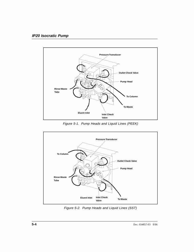
Pressure Transducer
Outlet Check Valve
Inlet Check Valve
To Column
Pump Head
Eluent Inlet
To Waste
Rinse WasteTube
Figure 5-1. Pump Heads and Liquid Lines (PEEK)
Pressure Transducer
Outlet Check Valve
Inlet Check Valve
To Column
Pump Head
To WasteEluent Inlet
Rinse WasteTube
Figure 5-2. Pump Heads and Liquid Lines (SST)
IP20 Isocratic Pump
5-4 Doc. 034857-03 8/96

7. The inlet check valve assembly housing has a 1/4-28 port.Replace the cartridge in the inlet check valve housing; thedouble-hole end of the cartridge should be visible. The outletcheck valve assembly housing has a 10-32 port. Replace thecartridge in the outlet check valve housing; the single-hole endof the cartridge should be visible. Liquid flows through thecheck valve in the large single hole and out the small doubleholes.
8. Reinstall the check valves. Make sure that the inlet check valveis installed on the bottom of the head and that the outlet checkvalve is installed on the top of the head. Tighten only enough toseat (25 in-lb torque). Tighten a little more only if it leaks.
Overtightening may damage the pump head and the checkvalve housing and crush the check valve seats.
9. Reconnect the liquid lines. Turn on the main power switch.
10. Prime the pump (see Section B.2.7). If the pump will not primeand all other possible causes of the problem have beeneliminated, replace the cartridge containing the check valve.
Check Valve Cartridge Type Part Number
Standard Bore PEEK 047747
Standard Bore Stainless Steel 047755
Microbore PEEK 047748
Microbore Stainless Steel 048279
11. After replacing check valve cartridges, open the ELAPSED TIME
screen (press Menu , 8, 2). Move the cursor to the VALVES IN USE
field and press Enter to reset the field to 0 cycles.
5 • Service
Doc. 034857-03 8/96 5-5
5.2 Piston Seal Replacement
A damaged seal allows leakage past the piston and then throughthe rinse ports in the front of the pump heads. Flow rates will below and erratic, producing chromatograms with longer thannormal retention times.
1. Turn off the main power switch.
2. Disconnect the tube fittings from the pressure transducer and theinlet check valve (see Figures 5-1 and 5-2).
3. Remove the two nuts from the pump head.
4. Carefully disengage the head from the piston by pulling the headstraight off and away from its mounting guides.
Lateral motion while disengaging the head from the pistonmay break the piston. If the piston is broken, be very carefulwhen removing it; broken pistons have sharp edges andcan cause cuts.
5. Place the head (front end down) on a clean work surface and liftoff the backup washer to expose the piston guide (seeFigures 5-3 and 5-4).
6. The pistons are captured by a magnetic retention system and arenot removed with the rest of the pump head assembly. Afterremoving the pump head, apply just enough lateral force toovercome the magnetic field and release the pistons.
IP20 Isocratic Pump
5-6 Doc. 034857-03 8/96
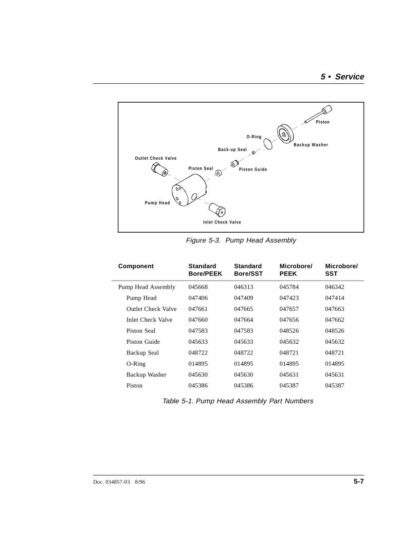
Component StandardBore/PEEK
StandardBore/SST
Microbore/PEEK
Microbore/SST
Pump Head Assembly 045668 046313 045784 046342
Pump Head 047406 047409 047423 047414
Outlet Check Valve 047661 047665 047657 047663
Inlet Check Valve 047660 047664 047656 047662
Piston Seal 047583 047583 048526 048526
Piston Guide 045633 045633 045632 045632
Backup Seal 048722 048722 048721 048721
O-Ring 014895 014895 014895 014895
Backup Washer 045630 045630 045631 045631
Piston 045386 045386 045387 045387
Table 5-1. Pump Head Assembly Part Numbers
Out le t Check Valve
In le t Check Valve
Pump Head
Piston Seal Pis ton Guide
Back-up Sea l
O-Ring
Backup Washer
Piston
Figure 5-3. Pump Head Assembly
5 • Service
Doc. 034857-03 8/96 5-7

7. To remove the piston guide and seal:
a. Fill the head cavity with deionized water by injecting througheither the piston opening or the inlet check valve.
b. Reinsert the piston approximately 1/8 in into the seal (seeFigure 5-4).
c. Install a 10-32 fitting plug (P/N 042772) on the outlet checkvalve and a 1/4-28 fitting plug (P/N 037628) on the inletcheck valve. Tighten the plugs.
d. Push the piston into the head. This action will hydraulicallyunseat the seal and piston guide from the head. Remove thepiston and pull off the guide and seal.
e. If the piston guide and seal do not come out, make sure the10-32 plugs are tight. Then, add more water and repeat Stepsb and d.
f. Remove the fitting plugs.
10 -32 F itting P lug(P/N 0427 72)
Outlet C heckValve
Pum pH ead
Inlet C heckValve
1/4-2 8 Fitting P lug(P/N 0376 28)
B ack up W asher(R em ov e )
Piston
Push in tounseat the sea land p iston gu ide .
Se al
P istonGu ide
R em ov e the p iston from thehead and pu ll of the se aland p iston gu ide .
Figure 5-4. Removing the Piston Seal
IP20 Isocratic Pump
5-8 Doc. 034857-03 8/96
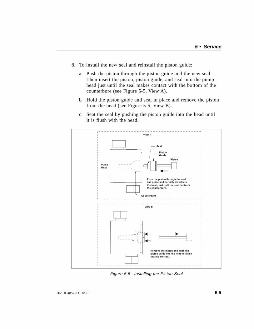
8. To install the new seal and reinstall the piston guide:
a. Push the piston through the piston guide and the new seal.Then insert the piston, piston guide, and seal into the pumphead just until the seal makes contact with the bottom of thecounterbore (see Figure 5-5, View A).
b. Hold the piston guide and seal in place and remove the pistonfrom the head (see Figure 5-5, View B).
c. Seat the seal by pushing the piston guide into the head untilit is flush with the head.
View A
Seal
PistonGuide
Piston
Push the piston throu gh the sealand g uide and partiall y insert intothe head, just until the seal contactsthe counterbore.
Counterbore
PumpHead
View B
Remove the piston and push thepiston gu ide into the head to finishseatin g the seal.
Figure 5-5. Installing the Piston Seal
5 • Service
Doc. 034857-03 8/96 5-9

9. Dionex recommends reinstalling the head and piston as a singleassembly so that the piston will center itself. To do this, firstpress the backup washer into the head until it is flush with theindented surface of the head. Then, insert the piston halfway intothe head. This ensures that the magnet in the follower picks upthe piston. (The follower is the cylinder that holds the piston inplace as it moves in and out of the pump head assembly.)Reinstall the head and piston assembly, using a wrench to tightenthe nuts evenly (12 in-lb torque).
10. Reconnect the liquid line to the inlet check valve.
11. Reconnect the tube fittings to the pressure transducer.
12. Turn on the main power switch.
13. Open the ELAPSED TIME screen (press Menu , 8, 2). Press Enter toreset the SEALS IN USE field to 0 cycles. The pump is ready fornormal operation.
5.3 Pump Piston Replacement
Continued leaking through the rinse ports after replacing thepiston seal (assuming the head is tight) indicates a dirty,scratched, or broken piston.
1. Turn off the main power switch.
2. Disconnect the tube fittings from the pressure transducer and theinlet check valve (see Figures 5-1 and 5-2).
3. Remove the two acorn nuts from the pump head.
Lateral motion while disengaging the head from the pistonmay break the piston. If the piston is broken, be very carefulwhen removing it since broken pistons have sharp edgesand can cause cuts.
IP20 Isocratic Pump
5-10 Doc. 034857-03 8/96
4. Slowly pull the head and allow it to separate from the housing.Carefully disengage the head from the piston by pulling the headstraight off and away from the mounting guides.
5. The pistons are captured by a magnetic retention system and arenot removed with the rest of the pump head assembly. Afterremoving the pump head, apply just enough lateral force toovercome the magnetic field and release the pistons.
6. If the piston is broken, also replace the piston seal (seeSection 5.2) and the backup seal.
7. Dionex recommends reinstalling the head and piston as a singleassembly so that the piston will center itself. First press thebackup washer into the head until it is flush with the indentedsurface of the head. Then, insert the piston halfway into thehead. This ensures that the magnet in the follower picks up thepiston. (The follower is the cylinder that holds the piston inplace as it moves in and out of the pump head assembly.)Reinstall the head and piston, using a wrench to tighten the nutsevenly (12 in-lb torque).
8. Reconnect the liquid line to the inlet check valve.
9. Reconnect the tube fittings to the pressure transducer.
10. Turn on the main power switch and prime the pump (seeSection B.2.7).
5.4 Pressure Transducer Pad and O-RingReplacement
A damaged pressure pad or O-ring will cause leakage around thebase of the pressure transducer housing at the compression nut.Flow rates will be low, resulting in chromatograms withexcessively long retention times.
1. Turn off the main power switch.
2. Disconnect the liquid lines between the pressure transducerhousing and the check valve housings (see Figure 5-1 and 5-2).
5 • Service
Doc. 034857-03 8/96 5-11
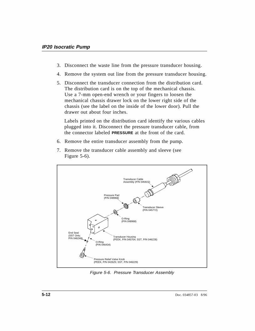
3. Disconnect the waste line from the pressure transducer housing.
4. Remove the system out line from the pressure transducer housing.
5. Disconnect the transducer connection from the distribution card.The distribution card is on the top of the mechanical chassis.Use a 7-mm open-end wrench or your fingers to loosen themechanical chassis drawer lock on the lower right side of thechassis (see the label on the inside of the lower door). Pull thedrawer out about four inches.
Labels printed on the distribution card identify the various cablesplugged into it. Disconnect the pressure transducer cable, fromthe connector labeled PRESSURE at the front of the card.
6. Remove the entire transducer assembly from the pump.
7. Remove the transducer cable assembly and sleeve (seeFigure 5-6).
Pressure Relief Valve Knob(PEEK, P/N 042625; SST, P/N 046229)
O-Ring(P/N 046434)
Transducer Housing(PEEK, P/N 045704; SST, P/N 046228)
O-Ring(P/N 048968)
Pressure Pad(P/N 048969)
Transducer Sleeve(P/N 045772)
Transducer CableAssembly (P/N 045922)
End Seal(SST Only; P/N 046240)
Figure 5-6. Pressure Transducer Assembly
IP20 Isocratic Pump
5-12 Doc. 034857-03 8/96

8. Install a new O-ring (P/N 048968) and pressure pad(P/N 048969) in the housing. Reinstall the transducer assemblyin the pump.
9. Reconnect the liquid lines from the check valve housings.Reconnect the outlet line and the waste line.
10. Reconnect the transducer cable to the distribution card.
11. Push the mechanical chassis drawer back in place, making surethe cables are not pinched. Retighten the drawer lock.
5.5 Pressure Transducer Waste Valve O-RingReplacement
A damaged O-ring causes leakage around the base of thepressure transducer waste valve knob. Flow rates will be low,resulting in chromatograms with longer retention times.
1. Turn off the main power switch.
2. Remove the valve from the pressure transducer housing byturning the knob counterclockwise until it comes loose from thehousing.
3. Cut through the O-ring with a razor blade, being careful not toscratch the valve body, and remove the O-ring.
4. Carefully slide a new O-ring (P/N 046434) over the end of thevalve and push it into the groove.
6. Reinstall the valve in the housing, turning the knob clockwiseuntil the valve is seated.
Overtightening the valve may damage the seat and pressuretransducer housing.
5 • Service
Doc. 034857-03 8/96 5-13
5.6 Changing Main Power Fuses
1. Turn off the main power switch.
HIGH VOLTAGE—Disconnect the main power cord from itssource and also from the rear panel of the IP20.
2. The fuse holder is part of the main power receptacle on the rearpanel (see Figure 5-7). A recessed lock is located on each side ofthe fuse holder. Using a small screwdriver or your fingernails,push each lock toward the center to release it. The fuse holderpops out approximately 0.16 cm (1⁄16 in) when the locks release.When both locks are released, pull the fuse holder straight out ofits compartment.
3. The holder contains two fuses. Replace these with new IEC127fast-blow fuses rated 3.15 amps (P/N 954745). Dionexrecommends replacing both fuses even though only one is open;because the other fuse has been stressed, it could fail even undernormal operation.
4. Reinsert the fuse holder into its compartment. The fuse holder iskeyed to fit only in its proper orientation. Apply sufficientpressure evenly against the holder to engage the two locks. Theholder is flush against the panel when both locks are engaged.
5. Reconnect the main power cord and turn on the power.
IP20 Isocratic Pump
5-14 Doc. 034857-03 8/96
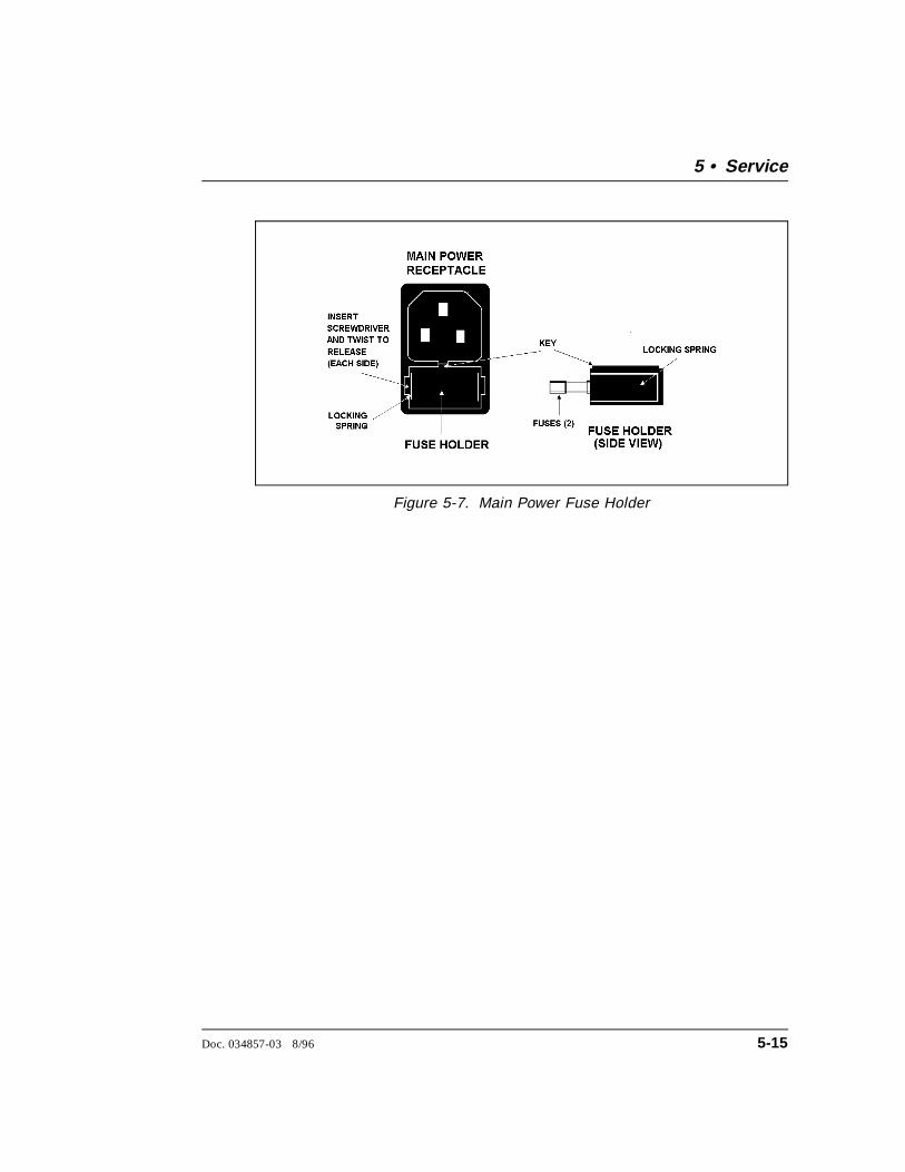
Figure 5-7. Main Power Fuse Holder
5 • Service
Doc. 034857-03 8/96 5-15
IP20 Isocratic Pump
5-16 Doc. 034857-03 8/96
A • Specifications
A.1 Electrical . . . . . . . . . . . . . . . . . . . . . . . A-3
A.2 Environmental . . . . . . . . . . . . . . . . . . . . A-3
A.3 Physical . . . . . . . . . . . . . . . . . . . . . . . A-3
A.4 Display and Keypad . . . . . . . . . . . . . . . . . A-3
A.5 Hydraulics . . . . . . . . . . . . . . . . . . . . . . A-4
A.6 Method Control . . . . . . . . . . . . . . . . . . . A-5
A.7 Vacuum Degas Assembly Option . . . . . . . . . A-5
Doc. 034857-03 8/96 A-1

IP20 Isocratic Pump
A-2 Doc. 034857-03 8/96
A • Specifications
A.1 Electrical
Main PowerRequirements
85 to 270 Vac, 47/63 Hz; 2.5 amps. The IP20 power supply ismain voltage auto-sensing and requires no adjustment.
FuseRequirements
Two 3.15 amp fast-blow IEC127 fuses (P/N 954745)
A.2 Environmental
OperatingTemperature
10 °C to 40 °C (50 °F to 104 °F)
OperatingHumidity
5 to 95% relative humidity (non-condensing)
A.3 Physical
Dimensions 33.5 cm high x 22.5 cm wide x 42 cm deep(13.1 in x 8.9 in x 16.8 in)6 cm (2.4 in) clearance required in back of the module
Weight 19 kg (42 lbs)
A.4 Display and Keypad
Display Liquid crystal with adjustable backlighting
Keypad 26-button keypad for entering commands and numericalvalues for screen parameters
Doc. 034857-03 8/96 A-3
A.5 Hydraulics
Pump Dual-piston, variable speed, 100 µL (standard bore), 25 µL(microbore) stroke; user-selectable constant pressure orconstant flow feedback control
Flow Rate Standard bore pump head: 0.04 to 10.0 mL/min, linearlyvariable in increments of 0.01 mL/min
Microbore pump head: 0.01 to 2.50 mL/min, linearly variablein increments of 0.01 mL/min
OperatingPressure
35 MPa (5000 psi) maximum
PressureResolution
0.07 MPa (10 psi)
High PressureLimit
0 to 35 MPa (0 to 5000 psi) in increments of 0.05 MPa (7.25 psi); trips instantaneously
Low PressureLimit
0 to 35 MPa (0 to 5000 psi) in increments of 0.05 MPa (7.25 psi); trips after a time-out of 0.4 mL for thestandard bore IP20 or 0.1 mL for the microbore IP20
Delay Volume Approximately 0.92 mL for standard pump heads or 0.72 mLfor microbore pump heads, measured from the inlet fitting upto and including the 61-cm (24-inch) pressure transduceroutlet line
IP20 Isocratic Pump
A-4 Doc. 034857-03 8/96
A.6 Method Control
Methods Stores up to 100 separate methods (00 to 99), each of whichmay contain up to 50 separate steps. The actual number ofstored methods depends on the available memory.
Control The keypad is used to select the pump’s operating parametersand to program methods.
Storage Non-volatile memory protects against the loss of programsduring power-down or in the event of a power failure.
Remote Limited remote operation via TTL-Input logic level, andTTL-output and relay contact closures, or full remoteprogramming and control through PeakNet software and theDX LAN interface.
A.7 Vacuum Degas Assembly Option
Channels Single-channel membrane vacuum degas
Materials Wetted materials, PEEK, PTFE
Performance >69% degas ratio @ 1 or 3 mL/min with 8.5 ppm O2 at input
0.200 Kg F/cm2 flow resistance @ 10 mL/min
A • Specifications
Doc. 034857-03 8/96 A-5

IP20 Isocratic Pump
A-6 Doc. 034857-03 8/96
B • Installation
B.1 Facility Requirements . . . . . . . . . . . . . . . . B-3
B.2 Installation Instructions . . . . . . . . . . . . . . . B-4
B.2.1 Power Connection . . . . . . . . . . . . . B-4
B.2.2 Electronics Chassis Connections . . . . . B-5
LC30 Connections . . . . . . . . . . . . B-5
LC10 or LC20 Connections . . . . . . B-6
B.2.3 DX LAN Network Connection (Optional) B-7
B.2.4 Waste Lines . . . . . . . . . . . . . . . . . B-9
B.2.5 Eluent Outlet Line Connection . . . . . . B-10
B.2.6 Eluent Inlet Line Connection . . . . . . . B-10
B.2.7 Priming the Pump . . . . . . . . . . . . . B-11
Priming the Eluent Inlet Lines . . . . . B-11
Priming the Pump Heads . . . . . . . . B-13
Priming the Pump Heads withIsopropyl Alcohol . . . . . . . . . . . . B-14
B.3 Automatic SRS Power Control . . . . . . . . . . . B-15
B.4 Stacking Modules . . . . . . . . . . . . . . . . . . B-17
B.5 Securing Modules (Optional) . . . . . . . . . . . . B-18
B.5.1 Installing a Shoe . . . . . . . . . . . . . . B-18
B.5.2 Installing a Tie . . . . . . . . . . . . . . . B-19
Doc. 034857-03 8/96 B-1

IP20 Isocratic Pump
B-2 Doc. 034857-03 8/96
B • Installation
B.1 Facility Requirements
• Make sure the IP20 installation site meets the electrical andenvironmental specifications listed in Appendix A
• Install the IP20 on a sturdy table or workbench with at least6 cm (2.4 in) free space behind the module for connections andventilation. Install the module at a height that ensures convenientviewing of the front panel display and access to the interior.
Lift the module only from the bottom or side surfaces.Lifting with the panel door will damage the door hinges.Use caution when lifting the module; it weighs 19 kg(42 lbs).
• Provide a source of helium, nitrogen, or argon gas to pressurizethe eluent and regenerant reservoirs. Helium is recommended.For details, refer to the Pressurizable Reservoir InstallationInstructions.
• Install a regulator (P/N 046594) on the gas supply line to thereservoir.
Doc. 034857-03 8/96 B-3

B.2 Installation Instructions
The IP20 Ship Kit contains items necessary for completing theinstallation.
IP20 Isocratic Pump Version Ship Kit
Standard bore with PEEK components P/N 047698
Standard bore with stainless steel components P/N 047911
Microbore with PEEK components P/N 047910
Microbore with stainless steel components P/N 047912
B.2.1 Power Connection
You can control power to the IP20 from the main powerswitch on either the IP20 or the LC30 Chromatography Oven(if present). In either case, no adjustment is required to selectthe line voltage.
• For on/off control from the IP20, connect the modularpower cord (IEC 320 C13), provided in the IP20 Ship Kit,from the main power receptacle on the rear panel (seeFigure B-1) to a grounded, single-phase, power source.
• For on/off control from the LC30 Chromatography Oven,connect the IEC jumper power cord (P/N 960748)provided in the LC30 Ship Kit from the main powerreceptacle on the IP20 rear panel to one of the four IECauxiliary receptacles on the rear panel of the LC30. Leavethe IP20 power switch on continuously and use the LC30main power switch to turn the IP20 on and off. Othermodules in the system can be connected to the LC30 inthe same way, allowing the LC30 to function as the mainpower source for the system.
SHOCK HAZARD—To avoid electrical shock, a groundedreceptacle must be used. Do not operate or connect to ACpower mains without an earthed ground connection.
IP20 Isocratic Pump
B-4 Doc. 034857-03 8/96
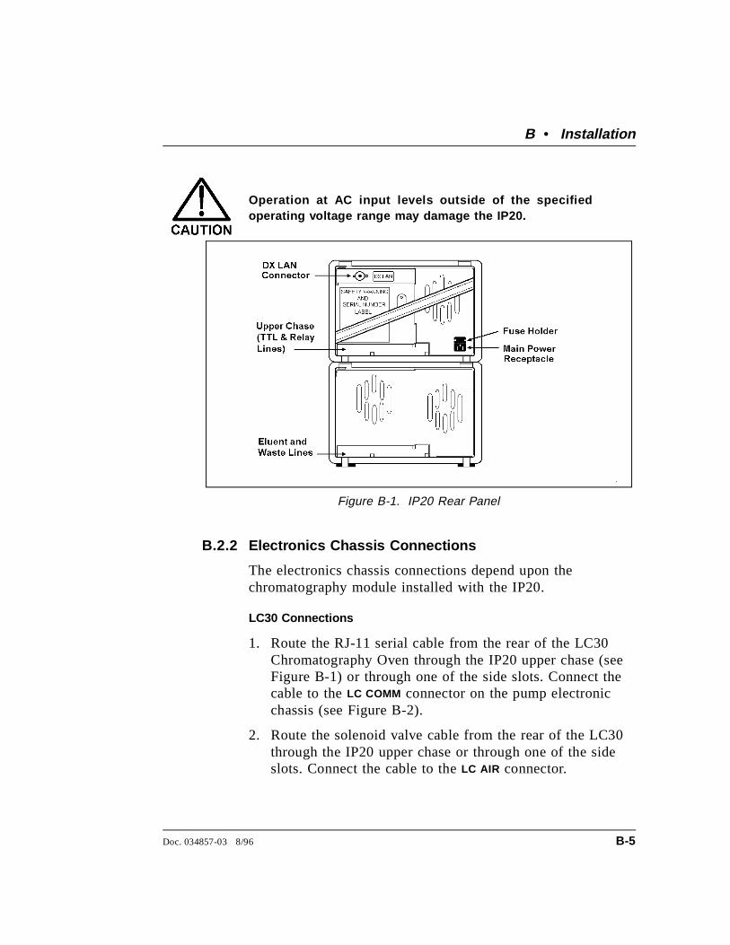
Operation at AC input levels outside of the specifiedoperating voltage range may damage the IP20.
B.2.2 Electronics Chassis Connections
The electronics chassis connections depend upon thechromatography module installed with the IP20.
LC30 Connections
1. Route the RJ-11 serial cable from the rear of the LC30Chromatography Oven through the IP20 upper chase (seeFigure B-1) or through one of the side slots. Connect thecable to the LC COMM connector on the pump electronicchassis (see Figure B-2).
2. Route the solenoid valve cable from the rear of the LC30through the IP20 upper chase or through one of the sideslots. Connect the cable to the LC AIR connector.
Figure B-1. IP20 Rear Panel
B • Installation
Doc. 034857-03 8/96 B-5
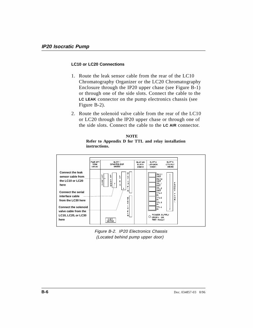
LC10 or LC20 Connections
1. Route the leak sensor cable from the rear of the LC10Chromatography Organizer or the LC20 ChromatographyEnclosure through the IP20 upper chase (see Figure B-1)or through one of the side slots. Connect the cable to theLC LEAK connector on the pump electronics chassis (seeFigure B-2).
2. Route the solenoid valve cable from the rear of the LC10or LC20 through the IP20 upper chase or through one ofthe side slots. Connect the cable to the LC AIR connector.
NOTERefer to Appendix D for TTL and relay installationinstructions.
Connect the solenoidvalve cable from theLC10, LC20, or LC30here
Connect the serialinterface cablefrom the LC30 here
Connect the leaksensor cable fromthe LC10 or LC20here
Figure B-2. IP20 Electronics Chassis (Located behind pump upper door)
IP20 Isocratic Pump
B-6 Doc. 034857-03 8/96
B.2.3 DX LAN Network Connection (Optional)
For the IP20 to communicate with PeakNet software, a pumpinterface card (P/N 044196) must be installed in the IP20 andthe DX LAN cable (P/N 960404) must be connected to theDX LAN connector on the IP20 rear panel.
STATIC—The IP20 electronics are not user-serviceable andthe pump interface card should be installed by qualifiedpersonnel only. Observe standard anti-static procedureswhen installing the interface card or handling the CPU card.
To prevent damage to the pump, turn off the main powerbefore installing the interface card. After confirming thatthe LED on the CPU card is off (not green or red), unplugthe power from the mains. Do not rely on the front panelpower switch.
1. Remove any TTL/Relay plugs from the connectors at slot4 on the electronic chassis (see Figure B-2).
2. Disconnect the 60-pin ribbon cable from the inside of thefront panel by first closing the tilt panel to expose theconnector and its ejector latches. Remove the cable byopening the ejector latches.
3. Using a screwdriver as a lever, open the white ejectorlatch at the bottom of the CPU card. Remove the CPUcard, cable, and Relay card as a single unit.
4. Insert the pump interface card (P/N 044195) into slot 4.Slide the card to the rear. Verify that the BNC connectoris aligned with the hole at the rear and the card is alignedwith the connector. Press firmly on the card until it matesfully with the connector on the rear panel.
5. Reinstall the CPU/Relay card. Press firmly until the CPUcard is inserted into the DX LAN connector on the rearpanel.
B • Installation
Doc. 034857-03 8/96 B-7

6. Reconnect the ribbon cable to the 60-pin connector on thefront panel. The header and connector are key-polarizednear the center. The ejector latches should be partiallyopen to accept the cable connector.
7. If the pump is the last module in the network to beconnected, install a terminator plug (P/N 921034),shipped with PeakNet software, on the remaining port ofthe BNC tee connector. If this is not the last module,connect the cable from the next module to the BNC tee.
Terminator resistor plugs must be installed at each end ofthe DX LAN. Verify that both ends of the DX LAN haveterminator resistor plugs installed.
8. Connect the DX LAN cable (P/N 960404) to the DX LANconnector on the rear panel.
IP20 Isocratic Pump
B-8 Doc. 034857-03 8/96
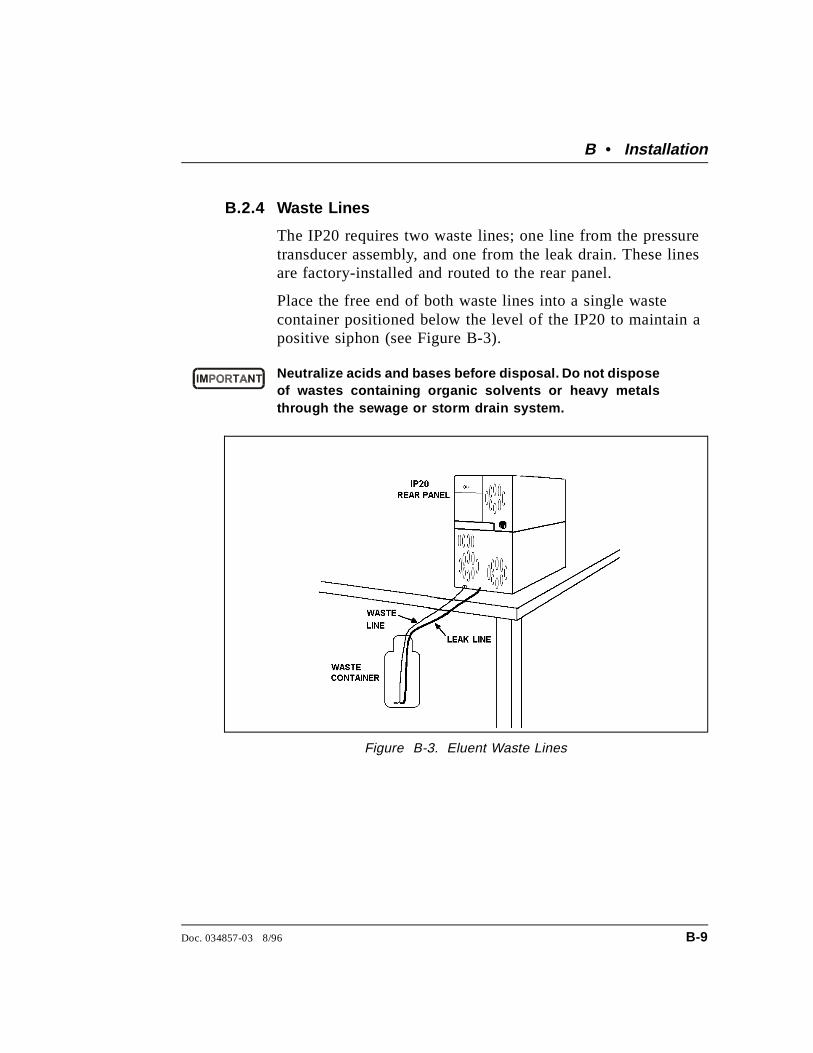
B.2.4 Waste Lines
The IP20 requires two waste lines; one line from the pressuretransducer assembly, and one from the leak drain. These linesare factory-installed and routed to the rear panel.
Place the free end of both waste lines into a single wastecontainer positioned below the level of the IP20 to maintain apositive siphon (see Figure B-3).
Neutralize acids and bases before disposal. Do not disposeof wastes containing organic solvents or heavy metalsthrough the sewage or storm drain system.
Figure B-3. Eluent Waste Lines
B • Installation
Doc. 034857-03 8/96 B-9
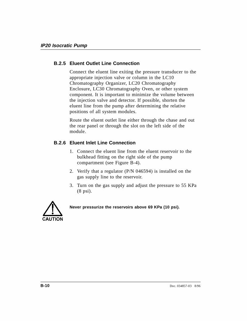
B.2.5 Eluent Outlet Line Connection
Connect the eluent line exiting the pressure transducer to theappropriate injection valve or column in the LC10Chromatography Organizer, LC20 ChromatographyEnclosure, LC30 Chromatography Oven, or other systemcomponent. It is important to minimize the volume betweenthe injection valve and detector. If possible, shorten theeluent line from the pump after determining the relativepositions of all system modules.
Route the eluent outlet line either through the chase and outthe rear panel or through the slot on the left side of themodule.
B.2.6 Eluent Inlet Line Connection
1. Connect the eluent line from the eluent reservoir to thebulkhead fitting on the right side of the pumpcompartment (see Figure B-4).
2. Verify that a regulator (P/N 046594) is installed on thegas supply line to the reservoir.
3. Turn on the gas supply and adjust the pressure to 55 KPa(8 psi).
Never pressurize the reservoirs above 69 KPa (10 psi).
IP20 Isocratic Pump
B-10 Doc. 034857-03 8/96
B.2.7 Priming the Pump
The priming procedure has two parts:
• Priming the eluent inlet lines
• Priming the pump heads
Priming the Eluent Inlet Lines
1. Press Menu and Enter to go to the MAIN screen. If REMOTE
mode is currently selected, move the cursor to that fieldand press a Select button to toggle to LOCAL mode. PressEnter or a cursor arrow button. If METHOD control iscurrently selected, move the cursor to that field, toggle toDIRECT CNTRL, and press Enter or an arrow button.
2. Verify that the Off/On LED is in the on position.
3. Set the flow rate to 0.
Bulkhead Fitting
Figure B-4. Bulkhead Fitting Location
B • Installation
Doc. 034857-03 8/96 B-11

4. Connect a 10 mL syringe (P/N 016387) to the lueradapter on the priming block. Turn the lever on thepriming block all the way to the left to its maximum openposition (see Figure B-5).
NOTEBecause the eluent is pressurized, liquid will flow intothe syringe as soon as you turn the priming blocklever.
5. Verify that the eluent is pressurized to 55 KPa (8 psi).
6. Use the syringe to draw liquid from the reservoir, andthrough the liquid lines, and the degas pump assembly (ifpresent). Continue drawing on the syringe until flowthrough the connecting tubing contains no more airbubbles. Because the degas assembly holds about 20 mL,you may need to draw several syringes of eluent.
Pressure TransducerWaste Valve
Figure B-5. Priming the Pump
IP20 Isocratic Pump
B-12 Doc. 034857-03 8/96
7. Move the lever on the priming block to the right to itsfully closed position (see Figure B-5).
8. Press Off/On twice to return the pump to its normaloperating mode.
Priming the Pump Heads
1. Go to the MAIN screen and select DIRECT CNTRL and LOCAL .
2. Open the pressure transducer waste valve (see Figure B-5)by turning the knob counterclockwise about two turns.When the waste valve is open, flow goes from thepriming block through the pump heads and directly out towaste (bypassing the eluent out line to the column).
Be sure to bypass all columns by opening the pressuretransducer waste valve before priming the pump. Thisprevents overpressurizing the system and possiblydamaging the columns.
3. Press Prime . The pump will begin pumping at itsmaximum flow rate (10.0 mL/min for standard bore and2.50 mL/min for microbore).
4. Allow the pump to prime until no bubbles can be seenexiting the waste line (about 5 minutes).
5. Press Prime again to return the flow to the normal rate.
6. Close the pressure transducer waste valve. The pump isnow ready for normal operation.
NOTEAfter priming, check the pressure reading on theMAIN screen. The IP20 display updates the pressurereadout once per piston stroke. The reading from onestroke to the next should be within 3%. A variation ofmore than 3% indicates the pump is out of prime. Ifthis is the case, go on to the following steps. Also referto Section 4.1 for troubleshooting information.
B • Installation
Doc. 034857-03 8/96 B-13
Priming the Pump Heads with Isopropyl Alcohol
NOTEPrime the pump heads with alcohol only if the regularprocedure, described on the previous page, is ineffective.
1. Connect a 10 mL syringe (P/N 016387) to the lueradapter on the priming block (see Figure B-5).
2. Open the pressure transducer waste valve by turning theknob counterclockwise about two turns.
3. Move the lever on the priming block to the left as far as itwill go (see Figure B-5). Press Prime .
4. Use the syringe to slowly push isopropyl alcohol throughthe pump. Avoid pushing any air trapped in the syringethrough the pump as this will result in loss of prime.Verify that alcohol with no trapped bubbles is travelingdown the waste line from the transducer.
5. Allow the pump to run until you have pushed about 3 mLof alcohol from the syringe. Then, while maintainingpressure on the syringe, press Off/On to turn off the pumpmotor.
6. Continue to push on the syringe until you have closed thepriming block valve by moving the lever all the way tothe right.
7. Press Prime and flush the pump with eluent for 2 minutesfor the standard bore pump heads, or 8 minutes for themicrobore pump heads.
If you do not completely flush the alcohol from the pumpbefore install ing the columns, the columns may beirreparably damaged.
8. Disconnect the syringe from the priming block and closethe pressure transducer waste valve. The pump is nowready for normal operation.
IP20 Isocratic Pump
B-14 Doc. 034857-03 8/96
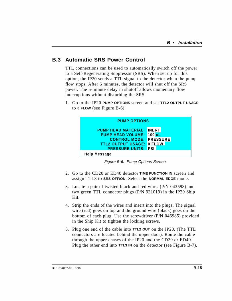
B.3 Automatic SRS Power Control
TTL connections can be used to automatically switch off the powerto a Self-Regenerating Suppressor (SRS). When set up for thisoption, the IP20 sends a TTL signal to the detector when the pumpflow stops. After 5 minutes, the detector will shut off the SRSpower. The 5-minute delay in shutoff allows momentary flowinterruptions without disturbing the SRS.
1. Go to the IP20 PUMP OPTIONS screen and set TTL2 OUTPUT USAGE
to 0 FLOW (see Figure B-6).
2. Go to the CD20 or ED40 detector TIME FUNCTION IN screen andassign TTL3 to SRS OFF/ON. Select the NORMAL EDGE mode.
3. Locate a pair of twisted black and red wires (P/N 043598) andtwo green TTL connector plugs (P/N 921019) in the IP20 ShipKit.
4. Strip the ends of the wires and insert into the plugs. The signalwire (red) goes on top and the ground wire (black) goes on thebottom of each plug. Use the screwdriver (P/N 046985) providedin the Ship Kit to tighten the locking screws.
5. Plug one end of the cable into TTL2 OUT on the IP20. (The TTLconnectors are located behind the upper door). Route the cablethrough the upper chases of the IP20 and the CD20 or ED40.Plug the other end into TTL3 IN on the detector (see Figure B-7).
Help Message
PUMP HEAD MATERIAL:PUMP HEAD VOLUME:
CONTROL MODE:
INERT100 uLPRESSURE
PUMP OPTIONS
TTL2 OUTPUT USAGE:PRESSURE UNITS:
0 FLOWPSI
Figure B-6. Pump Options Screen
B • Installation
Doc. 034857-03 8/96 B-15

NOTEFor correct operation, the CD20 or ED40 TTL3 inputmode must be set to NORMAL EDGE. Select the mode fromthe TIME FUNCTION IN screen.
Figure B-7. TTL Connections for SRS Power Control(CD20/ED40 and IP20 Front Views without Front Doors)
IP20 Isocratic Pump
B-16 Doc. 034857-03 8/96
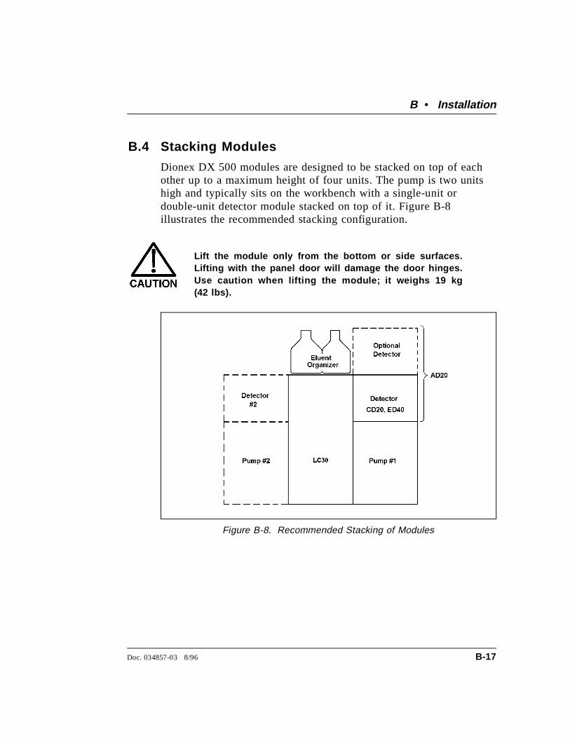
B.4 Stacking Modules
Dionex DX 500 modules are designed to be stacked on top of eachother up to a maximum height of four units. The pump is two unitshigh and typically sits on the workbench with a single-unit ordouble-unit detector module stacked on top of it. Figure B-8illustrates the recommended stacking configuration.
Lift the module only from the bottom or side surfaces.Lifting with the panel door will damage the door hinges.Use caution when lifting the module; it weighs 19 kg(42 lbs).
Figure B-8. Recommended Stacking of Modules
B • Installation
Doc. 034857-03 8/96 B-17

B.5 Securing Modules (Optional)
The Ship Kit contains a shoe (P/N 046478) and tie (P/N 046476) forsecuring modules together. Installation of the shoe and tie is optional.
• The shoe is a gray-colored rubber rectangle with raised edges. Itinstalls under two modules sitting side-by-side on the laboratorybench, for example, the LC30 Chromatography Oven and anIP20 Isocratic Pump.
• The tie is a small flexible piece of gray-colored rubber tubingwith enlarged square ends. It installs in the side slots of twoadjacent modules.
NOTEThe tie does not fit into the LC30 Chromatography Ovenslots because of the additional insulation required for theoven.
B.5.1 Installing a Shoe
1. The bottom of each module contains molded ribbing witha pocket on each side, midway between the front and therear of the module. One side of the shoe fits in the pocketof one module and the other side fits in the pocket of theadjacent module (see Figure B-9). To install the shoe, liftthe edge of one module away from the adjacent module.
2. Place the shoe, with the grooved side up, under the liftededge and slide the shoe along the edge until it fits into thepocket.
3. Press the shoe firmly into the pocket and carefully lowerthe module back onto the bench.
4. Lift the edge of the second module, align the front andrear edges of the two modules and then lower the secondmodule over the shoe. Press down to seat the secondmodule on the shoe.
IP20 Isocratic Pump
B-18 Doc. 034857-03 8/96
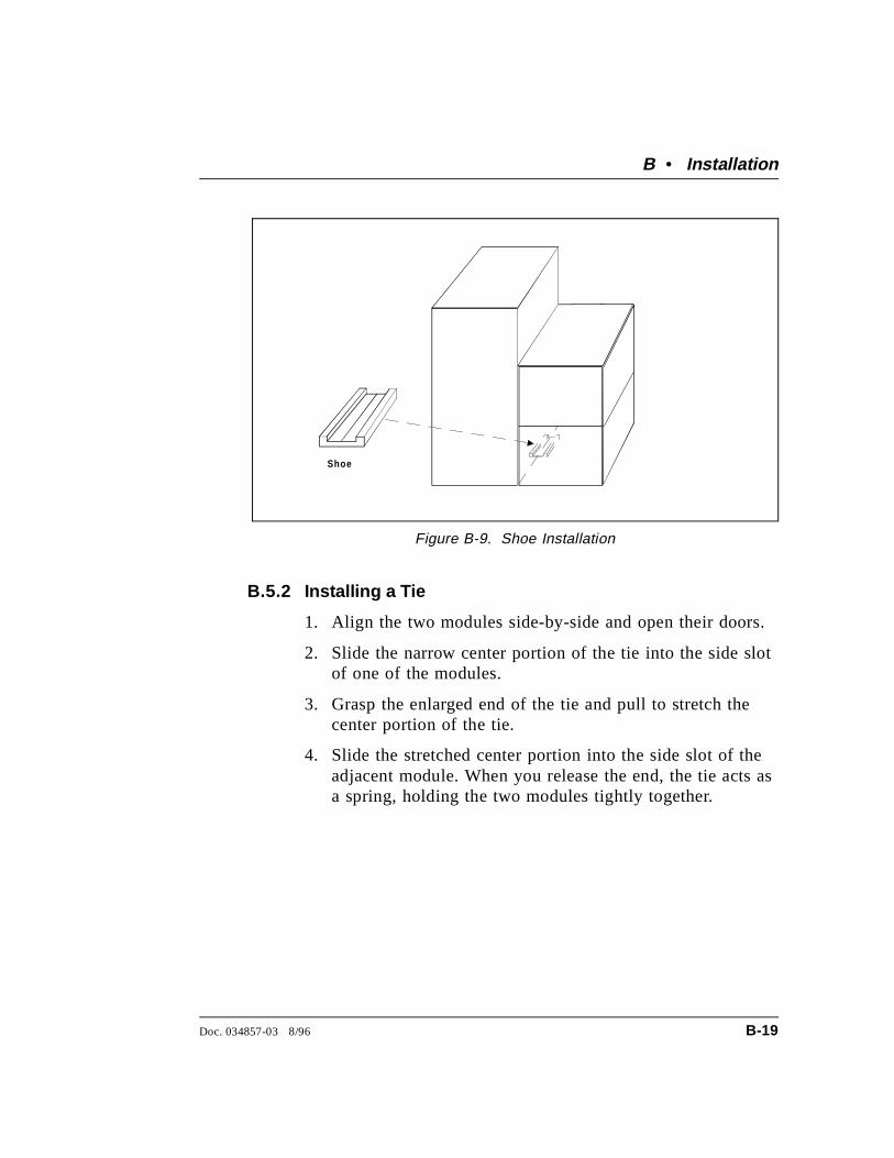
B.5.2 Installing a Tie
1. Align the two modules side-by-side and open their doors.
2. Slide the narrow center portion of the tie into the side slotof one of the modules.
3. Grasp the enlarged end of the tie and pull to stretch thecenter portion of the tie.
4. Slide the stretched center portion into the side slot of theadjacent module. When you release the end, the tie acts asa spring, holding the two modules tightly together.
Shoe
Figure B-9. Shoe Installation
B • Installation
Doc. 034857-03 8/96 B-19

IP20 Isocratic Pump
B-20 Doc. 034857-03 8/96
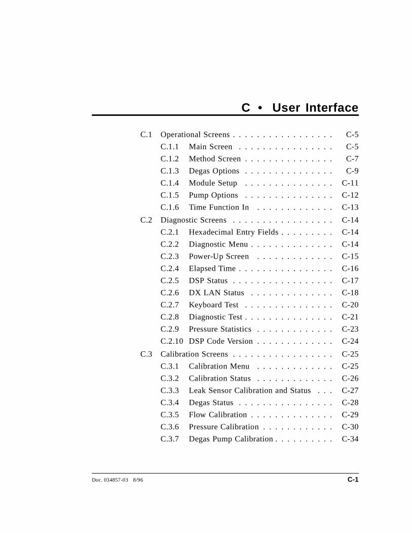
C • User Interface
C.1 Operational Screens . . . . . . . . . . . . . . . . . C-5
C.1.1 Main Screen . . . . . . . . . . . . . . . . C-5
C.1.2 Method Screen . . . . . . . . . . . . . . . C-7
C.1.3 Degas Options . . . . . . . . . . . . . . . C-9
C.1.4 Module Setup . . . . . . . . . . . . . . . C-11
C.1.5 Pump Options . . . . . . . . . . . . . . . C-12
C.1.6 Time Function In . . . . . . . . . . . . . C-13
C.2 Diagnostic Screens . . . . . . . . . . . . . . . . . C-14
C.2.1 Hexadecimal Entry Fields . . . . . . . . . C-14
C.2.2 Diagnostic Menu . . . . . . . . . . . . . . C-14
C.2.3 Power-Up Screen . . . . . . . . . . . . . C-15
C.2.4 Elapsed Time . . . . . . . . . . . . . . . . C-16
C.2.5 DSP Status . . . . . . . . . . . . . . . . . C-17
C.2.6 DX LAN Status . . . . . . . . . . . . . . C-18
C.2.7 Keyboard Test . . . . . . . . . . . . . . . C-20
C.2.8 Diagnostic Test . . . . . . . . . . . . . . . C-21
C.2.9 Pressure Statistics . . . . . . . . . . . . . C-23
C.2.10 DSP Code Version . . . . . . . . . . . . . C-24
C.3 Calibration Screens . . . . . . . . . . . . . . . . . C-25
C.3.1 Calibration Menu . . . . . . . . . . . . . C-25
C.3.2 Calibration Status . . . . . . . . . . . . . C-26
C.3.3 Leak Sensor Calibration and Status . . . C-27
C.3.4 Degas Status . . . . . . . . . . . . . . . . C-28
C.3.5 Flow Calibration . . . . . . . . . . . . . . C-29
C.3.6 Pressure Calibration . . . . . . . . . . . . C-30
C.3.7 Degas Pump Calibration . . . . . . . . . . C-34
Doc. 034857-03 8/96 C-1

IP20 Isocratic Pump
C-2 Doc. 034857-03 8/96

C • User Interface
This appendix illustrates and describes all of the screens availablefor display on the front panel of the IP20. There are three categoriesof screens: operational, diagnostic, and calibration (see Figure C-1).
• Operational screens allow you to create, edit, and run methodsthat control pump operation, and to select default pumpparameters.
• Diagnostic screens provide access to IP20 diagnostic informationand tests.
• Calibration screens allow you to calibrate various IP20functions; for example, the flow rate and the pressure offset.
MENU of SCREENS
POWER-UPSCREEN
ELAPSEDTIME DSP STATUS DX-LAN
STATUSKEYBOARD
TESTPRESSURESTATISTICS
METHOD PUMPOPTIONS
TIMEFUNCTION IN
MAINSCREEN
DIAGNOSTICMENU
DIAGNOSTICTEST
CALIBRATIONMENU
DEGASSTATUS
LEAK CAL& STATUS
FLOWCALIBRATION
PRESSUREOFFSET
CALIBRATION
DEGAS PUMPCALIBRATION
CALIBRATIONSTATUS
1 3 5 6 7 8
1 2 3 5 6 7 84 9
1 2 3 5 64
DSP CODEVERSION
Operational Screens
Diagnostic Screens
Calibration Screens
MODULESETUP
DEGASOPTIONS
4
Figure C-1. IP20 Menu Structure
Doc. 034857-03 8/96 C-3

Menu of Screens
This screen provides top-level access to the IP20 operationalscreens and to the DIAGNOSTICS MENU. It is displayed whenyou press Menu .
There are two ways to select a screen from a menu:
1. Move the cursor to the field containing the screen numberand press Enter .
2. Press the number button on the front panel keypad thatcorresponds to the screen number in the menu.
To display a brief description of each screen, press Help.
Help Messa ge
MAIN SCREEN
METHOD- - -
MODULE SETUPPUMP OPTIONSTIME FUNCTION INDIAGNOSTIC MENU
1234
5678
MENU of SCREENS
DEGAS OPTIONS
Figure C-2. Menu of Screens
IP20 Isocratic Pump
C-4 Doc. 034857-03 8/96
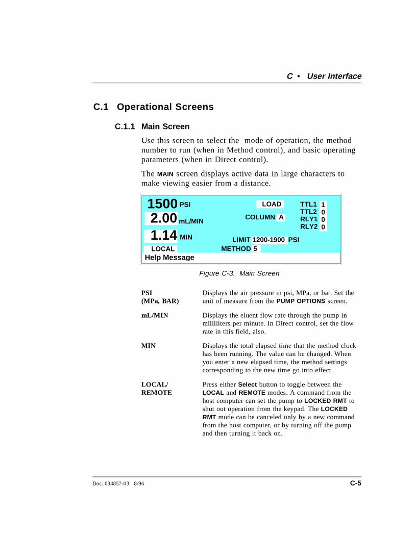
C.1 Operational Screens
C.1.1 Main Screen
Use this screen to select the mode of operation, the methodnumber to run (when in Method control), and basic operatingparameters (when in Direct control).
The MAIN screen displays active data in large characters tomake viewing easier from a distance.
PSI (MPa, BAR)
Displays the air pressure in psi, MPa, or bar. Set theunit of measure from the PUMP OPTIONS screen.
mL/MIN Displays the eluent flow rate through the pump inmilliliters per minute. In Direct control, set the flowrate in this field, also.
MIN Displays the total elapsed time that the method clockhas been running. The value can be changed. Whenyou enter a new elapsed time, the method settingscorresponding to the new time go into effect.
LOCAL/REMOTE
Press either Select button to toggle between theLOCAL and REMOTE modes. A command from thehost computer can set the pump to LOCKED RMT toshut out operation from the keypad. The LOCKEDRMT mode can be canceled only by a new commandfrom the host computer, or by turning off the pumpand then turning it back on.
Help Messa ge
PSI TTL1TTL2RLY1RLY2
METHOD
1000
COLUMN A
1500 mL/MIN2.00MIN1.14
LOCAL
LOAD
LIMIT51200-1900 PSI
Figure C-3. Main Screen
C • User Interface
Doc. 034857-03 8/96 C-5

INJECT/LOAD Selects the position of the injection valve. Thechoices are INJECT and LOAD .
COLUMN Selects the active column (A or B) in the LC10,LC20, or LC30 chromatography module. Column Bis available only when a column switching valve isinstalled in the chromatography module.
LIMIT The pressure limit range value in psi, MPa, or bar(see Section 3.1.5).
METHOD # Displays the number of the method currently running.The range is 0 through 99. In Local mode, enter themethod number to run in this field.
TTL1TTL2RLY1RLY2
Provides TTL and relay control of other devices. InDirect control, select 1 (on) or 0 (off). In Methodcontrol, set the TTL and relay fields from theMETHOD screen. Appendix D describes TTL andrelay control.
IP20 Isocratic Pump
C-6 Doc. 034857-03 8/96
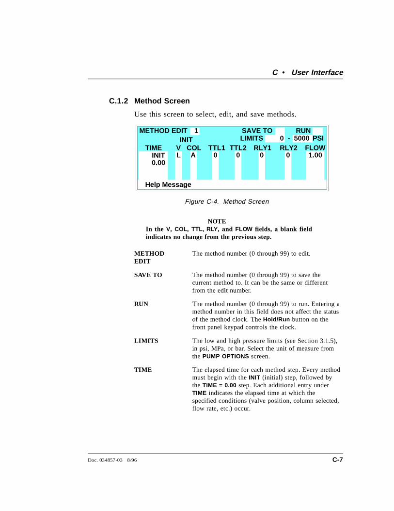
C.1.2 Method Screen
Use this screen to select, edit, and save methods.
NOTEIn the V, COL, TTL, RLY , and FLOW fields, a blank fieldindicates no change from the previous step.
METHODEDIT
The method number (0 through 99) to edit.
SAVE TO The method number (0 through 99) to save thecurrent method to. It can be the same or differentfrom the edit number.
RUN The method number (0 through 99) to run. Entering amethod number in this field does not affect the statusof the method clock. The Hold/Run button on thefront panel keypad controls the clock.
LIMITS The low and high pressure limits (see Section 3.1.5),in psi, MPa, or bar. Select the unit of measure fromthe PUMP OPTIONS screen.
TIME The elapsed time for each method step. Every methodmust begin with the INIT (initial) step, followed bythe TIME = 0.00 step. Each additional entry underTIME indicates the elapsed time at which thespecified conditions (valve position, column selected,flow rate, etc.) occur.
Help Message
COL FLOWA
METHOD EDITLIMITS 0 - 5000SAVE TO RUN
TIMEL 1.00
INIT
0.00
PSIV RLY1TTL1 TTL2 RLY2
0 0 0 0
1
INIT
Figure C-4. Method Screen
C • User Interface
Doc. 034857-03 8/96 C-7
V The position of the injection valve, either Inject orLoad.
COL Selects the active column (A or B) in the LC10,LC20, or LC30 chromatography module. Column Bis available only when a column switching valve isinstalled in the chromatography module.
TTL1TTL2RLY1RLY2
Provides TTL and relay control of other devices.Select 1 (on) or 0 (off). Appendix D describes TTLand relay control.
FLOW The flow rate through the pump inmilliliters-per-minute.
v A small “v” adjacent to the bottommost time entryindicates there are additional lines below the last linein the screen. Use the arrow buttons to scroll down tothe additional lines.
^ A caret (^) adjacent to the topmost time entryindicates there are additional lines above the top line.The caret displays only when the screen is scrolleddown additional lines. Use the arrow buttons to scrollup to the additional lines.
IP20 Isocratic Pump
C-8 Doc. 034857-03 8/96

C.1.3 Degas Options
Use the DEGAS OPTIONS screen to set the duration andfrequency of the degas pump cycles.
DEGAS PUMP Selects operating options:BY SETTING: The degas pump runs according to theselected degas options.MONITOR: The IP20 checks the degas vacuumreading once a minute. If the reading falls 500 countsbelow the calibration threshold value, the degas pumpturns on for the cycle duration time.ALWAYS OFF : The pump is always off.ALWAYS ON : The pump is always on. This setting isnormally used only for testing the pump duringservicing.
START-UP DURATIONThe time the pump runs at power-up (2-5 min).
CYCLE DURATION
The time the pump runs during each cycle (0-120 sec).
TIME BETWEENCYCLES
The time to wait between cycles (1-99 min).
NOTEThe DEGAS PUMP CALIBRATION screen displays thedegas threshold value.
Help Message
DEGAS PUMP:
DEGAS OPTIONS
START-UP DURATION: 2
TIME BETWEEN CYCLES:
MIN
10
BY SETTING
CYCLE DURATION: SECMIN
30
DEFAULT
2 MIN
10SECMIN
30
Figure C-5. Degas Options Screen
C • User Interface
Doc. 034857-03 8/96 C-9
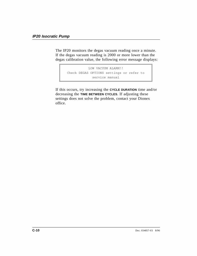
The IP20 monitors the degas vacuum reading once a minute.If the degas vacuum reading is 2000 or more lower than thedegas calibration value, the following error message displays:
LOW VACUUM ALARM!!
Check DEGAS OPTIONS settings or refer to
service manual
If this occurs, try increasing the CYCLE DURATION time and/ordecreasing the TIME BETWEEN CYCLES . If adjusting thesesettings does not solve the problem, contact your Dionexoffice.
IP20 Isocratic Pump
C-10 Doc. 034857-03 8/96
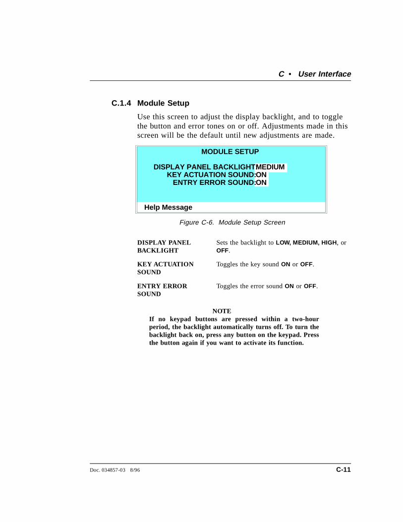
C.1.4 Module Setup
Use this screen to adjust the display backlight, and to togglethe button and error tones on or off. Adjustments made in thisscreen will be the default until new adjustments are made.
DISPLAY PANELBACKLIGHT
Sets the backlight to LOW, MEDIUM, HIGH, orOFF.
KEY ACTUATIONSOUND
Toggles the key sound ON or OFF.
ENTRY ERRORSOUND
Toggles the error sound ON or OFF.
NOTEIf no keypad buttons are pressed within a two-hourperiod, the backlight automatically turns off. To turn thebacklight back on, press any button on the keypad. Pressthe button again if you want to activate its function.
Help Message
DISPLAY PANEL BACKLIGHT:KEY ACTUATION SOUND:
ENTRY ERROR SOUND:
MEDIUMONON
MODULE SETUP
Figure C-6. Module Setup Screen
C • User Interface
Doc. 034857-03 8/96 C-11
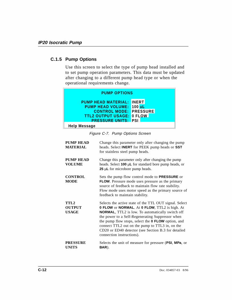
C.1.5 Pump Options
Use this screen to select the type of pump head installed andto set pump operation parameters. This data must be updatedafter changing to a different pump head type or when theoperational requirements change.
PUMP HEADMATERIAL
Change this parameter only after changing the pumpheads. Select INERT for PEEK pump heads or SSTfor stainless steel pump heads.
PUMP HEADVOLUME
Change this parameter only after changing the pumpheads. Select 100 µL for standard bore pump heads, or25 µL for microbore pump heads.
CONTROLMODE
Sets the pump flow control mode to PRESSURE orFLOW. Pressure mode uses pressure as the primarysource of feedback to maintain flow rate stability.Flow mode uses motor speed as the primary source offeedback to maintain stability.
TTL2OUTPUTUSAGE
Selects the active state of the TTL OUT signal. Select0 FLOW or NORMAL . At 0 FLOW, TTL2 is high. AtNORMAL , TTL2 is low. To automatically switch offthe power to a Self-Regenerating Suppressor whenthe pump flow stops, select the 0 FLOW option, andconnect TTL2 out on the pump to TTL3 in, on theCD20 or ED40 detector (see Section B.3 for detailedconnection instructions).
PRESSUREUNITS
Selects the unit of measure for pressure (PSI, MPa, orBAR ).
Help Message
PUMP HEAD MATERIAL:PUMP HEAD VOLUME:
CONTROL MODE:
INERT100 uLPRESSURE
PUMP OPTIONS
TTL2 OUTPUT USAGE:PRESSURE UNITS:
0 FLOWPSI
Figure C-7. Pump Options Screen
IP20 Isocratic Pump
C-12 Doc. 034857-03 8/96
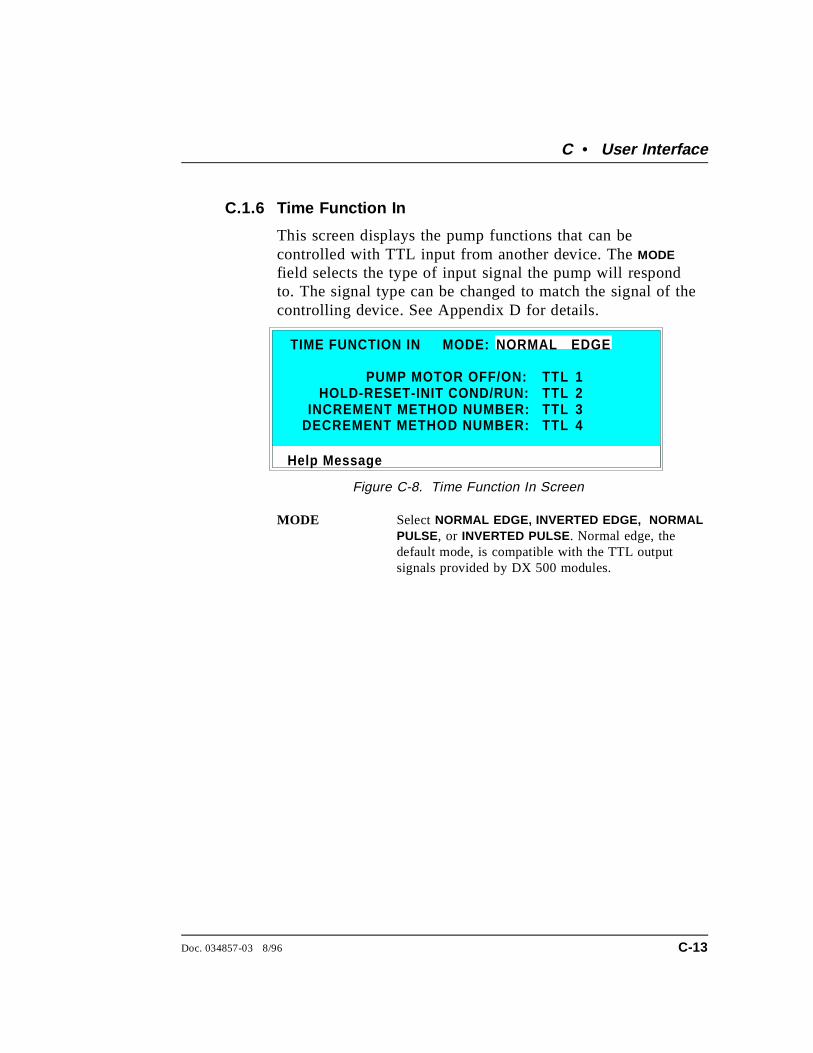
C.1.6 Time Function In
This screen displays the pump functions that can becontrolled with TTL input from another device. The MODE
field selects the type of input signal the pump will respondto. The signal type can be changed to match the signal of thecontrolling device. See Appendix D for details.
MODE Select NORMAL EDGE, INVERTED EDGE, NORMALPULSE, or INVERTED PULSE. Normal edge, thedefault mode, is compatible with the TTL outputsignals provided by DX 500 modules.
Help Message
HOLD-RESET-INIT COND/RUN:INCREMENT METHOD NUMBER:
1234
TIME FUNCTION IN
PUMP MOTOR OFF/ON:
MODE: NORMAL EDGE
TTLTTLTTLTTLDECREMENT METHOD NUMBER:
Figure C-8. Time Function In Screen
C • User Interface
Doc. 034857-03 8/96 C-13
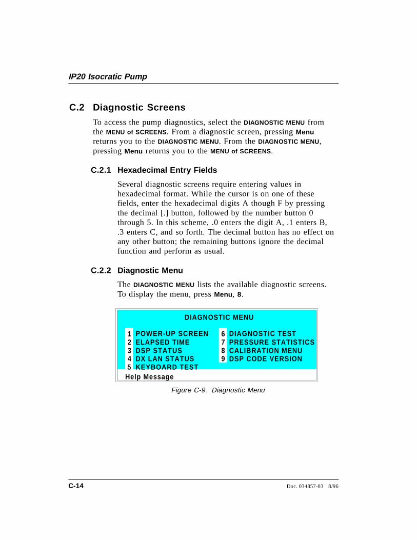
C.2 Diagnostic Screens
To access the pump diagnostics, select the DIAGNOSTIC MENU fromthe MENU of SCREENS . From a diagnostic screen, pressing Menureturns you to the DIAGNOSTIC MENU. From the DIAGNOSTIC MENU,pressing Menu returns you to the MENU of SCREENS .
C.2.1 Hexadecimal Entry Fields
Several diagnostic screens require entering values inhexadecimal format. While the cursor is on one of thesefields, enter the hexadecimal digits A though F by pressingthe decimal [.] button, followed by the number button 0through 5. In this scheme, .0 enters the digit A, .1 enters B,.3 enters C, and so forth. The decimal button has no effect onany other button; the remaining buttons ignore the decimalfunction and perform as usual.
C.2.2 Diagnostic Menu
The DIAGNOSTIC MENU lists the available diagnostic screens.To display the menu, press Menu , 8.
Help Message
POWER-UP SCREENELAPSED TIMEDSP STATUSDX LAN STATUS
DIAGNOSTIC TESTPRESSURE STATISTICSCALIBRATION MENUDSP CODE VERSION
12345
678
DIAGNOSTIC MENU
KEYBOARD TEST9
Figure C-9. Diagnostic Menu
IP20 Isocratic Pump
C-14 Doc. 034857-03 8/96
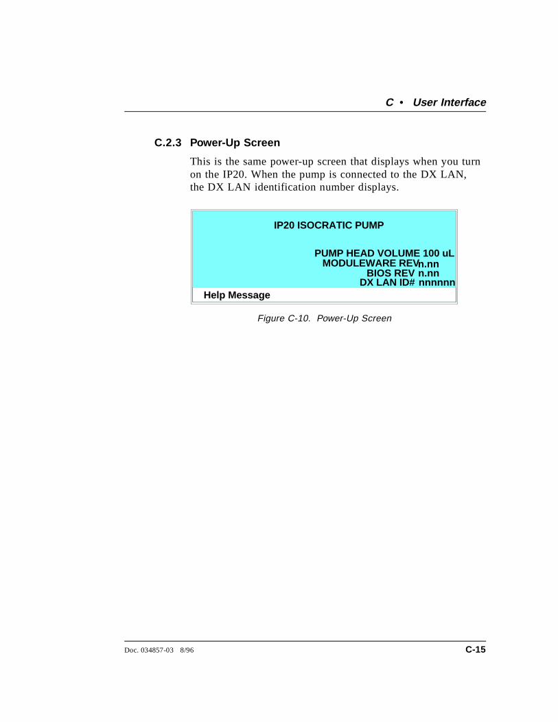
C.2.3 Power-Up Screen
This is the same power-up screen that displays when you turnon the IP20. When the pump is connected to the DX LAN,the DX LAN identification number displays.
Help Message
IP20 ISOCRATIC PUMP
PUMP HEAD VOLUME 100 uLMODULEWARE REVn.nn
BIOS REVnnnnnnDX LAN ID#n.nn
Figure C-10. Power-Up Screen
C • User Interface
Doc. 034857-03 8/96 C-15
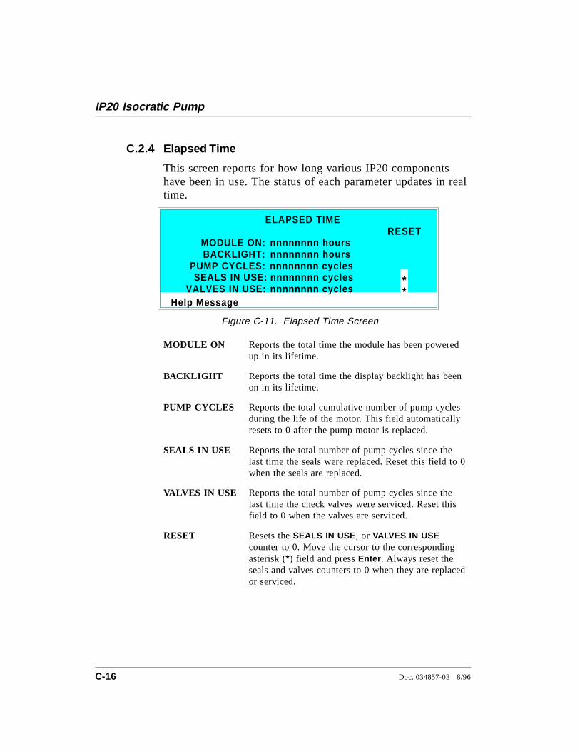
C.2.4 Elapsed Time
This screen reports for how long various IP20 componentshave been in use. The status of each parameter updates in realtime.
MODULE ON Reports the total time the module has been poweredup in its lifetime.
BACKLIGHT Reports the total time the display backlight has beenon in its lifetime.
PUMP CYCLES Reports the total cumulative number of pump cyclesduring the life of the motor. This field automaticallyresets to 0 after the pump motor is replaced.
SEALS IN USE Reports the total number of pump cycles since thelast time the seals were replaced. Reset this field to 0when the seals are replaced.
VALVES IN USE Reports the total number of pump cycles since thelast time the check valves were serviced. Reset thisfield to 0 when the valves are serviced.
RESET Resets the SEALS IN USE , or VALVES IN USEcounter to 0. Move the cursor to the correspondingasterisk (*) field and press Enter . Always reset theseals and valves counters to 0 when they are replacedor serviced.
Help Message
ELAPSED TIME
MODULE ON: nnnnnnnn hoursBACKLIGHT: nnnnnnnn hours
PUMP CYCLES: nnnnnnnn cyclesSEALS IN USE: nnnnnnnn cycles
VALVES IN USE: nnnnnnnn cycles
RESET
**
Figure C-11. Elapsed Time Screen
IP20 Isocratic Pump
C-16 Doc. 034857-03 8/96

C.2.5 DSP Status
This screen reports the status of IP20 DSP (Digital SignalProcessor) dynamic parameters. Status updates are in real time.
PRESSURE Reports the current head pressure in psi, MPa, or bar.
TACH VALUE Reports the current motor tachometer reading in volts.
FLOW MODE Reports the flow mode as ON or OFF:ON = System is in constant flow mode.OFF = System is in pressure feedback mode.
HEADMATERIAL
Reports the head material as set from the PUMPOPTIONS screen:INERT = PEEK headsMETAL = Stainless steel heads
EN. FOUND Reports when the encoder is found. Options are YESor NO.
HEAD VOLUME Reports the head volume as set from the PUMPOPTIONS screen. The options are 100 µL forstandard bore heads or 25 µL for microbore heads.
PRESSURIZA-TION POINTS
Reports the current pressurization point for the leftand right pistons. The pressurization points are thepoints at which the pump speed is adjusted at eachstroke to maintain a constant flow rate. When thepump has stabilized, the left and right values areapproximately equal (within 5). A variation of morethan 3% between the left and right readings indicatesa problem (see Section 4.1).
Help Message
DSP STATUS
PRESSURIZATION POINTSLEFT: RIGHT:nnn nnn
TACH VALUE: 5.00 VHEAD MATERIAL: INERT
HEAD VOLUME: 100uL
PRESSURE:FLOW MODE:
EN. FOUND:
nnnn PSIOFFYES
Figure C-12. DSP Status Screen
C • User Interface
Doc. 034857-03 8/96 C-17

C.2.6 DX LAN Status
The DX LAN driver monitors several types of errors that mayoccur on the network. The detector reads the DX LAN errorcounts and displays them on this screen, along with the DXLAN addresses.
UNIQUE DX LAN ID Displays the three-byte DX LAN IDprogrammed into the pump Moduleware (inHEX). The ID is unique to the pump andnever changes.
DX LAN ADDRESS Displays the six-byte DX LAN addressassigned by the PC (in HEX). The first threebytes are the system assignment and the lastthree bytes are the assignment within thesystem.
COLLISION Indicates that 16 unsuccessful transmissions ofthe same packet occurred, due to collisions.
BUS WRITE Indicates that a ready response could not beissued within 2.4 microseconds after the WRsignal was asserted. This occurs when thetransmit buffer memory is full.
UNDERFLOW Indicates that data from the transmit section ofthe hardware buffer memory is not availablefor serial transmission. The DX LAN willcontinue to send out this data frame.
ALIGNMENT Indicates that a packet was received with analignment error, meaning that there were one
Help Message
UNIQUE ID:DX LAN STATUS
LAN ADDRESS:
COLLISION: ALIGNMENT:
UNDERFLOW:BUS WRITE:
nnn nnn
nnnnnn
FF FF FFFF FF FF FF FF FF
RETRY:
CRC:
OVERFLOW:BUS READ: nnn
nnnRUNT:
nnnnnnnnn
Figure C-13. DX LAN Status Screen
IP20 Isocratic Pump
C-18 Doc. 034857-03 8/96
to seven extra bits at the end of the packet.This is usually caused by a collision or afaulty transceiver.
BUS READ Indicates that a ready response could not beissued within 2.4 microseconds after the readysignal was asserted. This occurs when readingan empty buffer.
OVERFLOW Indicates that the DX LAN hardware receivebuffer became full and had to reject a packetfor lack of space.
CRC Indicates that a packet was received with aCRC error. This usually means that a collisionhas corrupted the packet.
RUNT Indicates that a “runt” packet (one less than 15bytes in length) was received. This usuallyoccurs after a collision has truncated theoriginal length.
RETRY Indicates the number of retries required totransmit the last packet.
C • User Interface
Doc. 034857-03 8/96 C-19
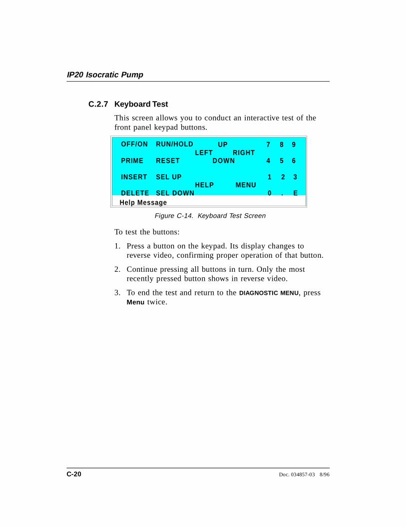
C.2.7 Keyboard Test
This screen allows you to conduct an interactive test of thefront panel keypad buttons.
To test the buttons:
1. Press a button on the keypad. Its display changes toreverse video, confirming proper operation of that button.
2. Continue pressing all buttons in turn. Only the mostrecently pressed button shows in reverse video.
3. To end the test and return to the DIAGNOSTIC MENU, pressMenu twice.
Help Message
OFF/ON
PRIME
INSERT
DELETE
RUN/HOLD
RESET
SEL UP
SEL DOWN
UP 7 8 9
4 5 6
1 2 3
0 . E
DOWNLEFT RIGHT
HELP MENU
Figure C-14. Keyboard Test Screen
IP20 Isocratic Pump
C-20 Doc. 034857-03 8/96
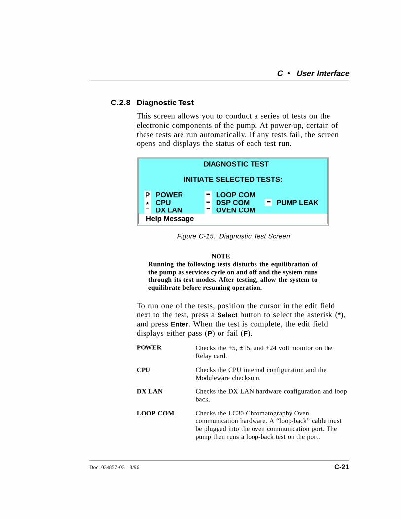
C.2.8 Diagnostic Test
This screen allows you to conduct a series of tests on theelectronic components of the pump. At power-up, certain ofthese tests are run automatically. If any tests fail, the screenopens and displays the status of each test run.
NOTERunning the following tests disturbs the equilibration ofthe pump as services cycle on and off and the system runsthrough its test modes. After testing, allow the system toequilibrate before resuming operation.
To run one of the tests, position the cursor in the edit fieldnext to the test, press a Select button to select the asterisk (*),and press Enter . When the test is complete, the edit fielddisplays either pass (P) or fail (F).
POWER Checks the +5, ±15, and +24 volt monitor on theRelay card.
CPU Checks the CPU internal configuration and theModuleware checksum.
DX LAN Checks the DX LAN hardware configuration and loopback.
LOOP COM Checks the LC30 Chromatography Ovencommunication hardware. A “loop-back” cable mustbe plugged into the oven communication port. Thepump then runs a loop-back test on the port.
Help Message
DIAGNOSTIC TEST
POWERCPUDX LAN
P*-
LOOP COMDSP COMOVEN COM
--- PUMP LEAK-
INITIATE SELECTED TESTS:
Figure C-15. Diagnostic Test Screen
C • User Interface
Doc. 034857-03 8/96 C-21
DSP COM Checks communication between the pump CPU andthe DSP (Digital Signal Processor) hardware bysending a command and waiting for the appropriateresponse.
PUMP LEAK Checks the pump’s leak sensor for a correct, opencircuit, or short circuit condition.
EXTERNAL LEAK
Checks the external leak sensor for a correct, opencircuit, or short circuit condition.
NOTEExiting the DIAGNOSTIC TEST screen clears the pass/failindicators from the edit fields.
IP20 Isocratic Pump
C-22 Doc. 034857-03 8/96
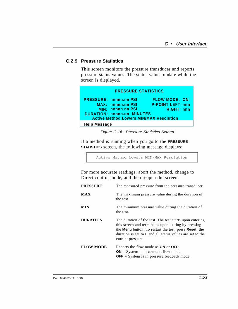
C.2.9 Pressure Statistics
This screen monitors the pressure transducer and reportspressure status values. The status values update while thescreen is displayed.
If a method is running when you go to the PRESSURE
STATISTICS screen, the following message displays:
Active Method Lowers MIN/MAX Resolution
For more accurate readings, abort the method, change toDirect control mode, and then reopen the screen.
PRESSURE The measured pressure from the pressure transducer.
MAX The maximum pressure value during the duration ofthe test.
MIN The minimum pressure value during the duration ofthe test.
DURATION The duration of the test. The test starts upon enteringthis screen and terminates upon exiting by pressingthe Menu button. To restart the test, press Reset ; theduration is set to 0 and all status values are set to thecurrent pressure.
FLOW MODE Reports the flow mode as ON or OFF:ON = System is in constant flow mode.OFF = System is in pressure feedback mode.
Help Message
PRESSURE:
PRESSURE STATISTICS
MAX:nnnnn.nn PSI
RIGHT:
FLOW MODE:
MIN:P-POINT LEFT:
ONnnn
MINUTESDURATION:
nnnnn.nn PSI
nnnnn.nn nnnnn.nn PSI nnn
Active Method Lowers MIN/MAX Resolution
Figure C-16. Pressure Statistics Screen
C • User Interface
Doc. 034857-03 8/96 C-23
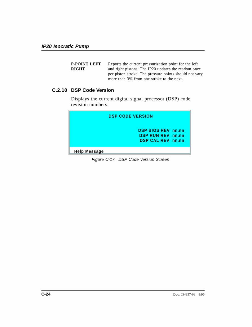
P-POINT LEFTRIGHT
Reports the current pressurization point for the leftand right pistons. The IP20 updates the readout onceper piston stroke. The pressure points should not varymore than 3% from one stroke to the next.
C.2.10 DSP Code Version
Displays the current digital signal processor (DSP) coderevision numbers.
Help Message
DSP CODE VERSION
DSP BIOS REVDSP RUN REV nn.nnDSP CAL REV
nn.nn
nn.nn
Figure C-17. DSP Code Version Screen
IP20 Isocratic Pump
C-24 Doc. 034857-03 8/96
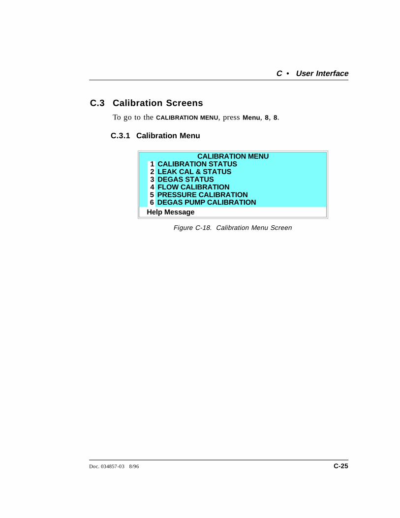
C.3 Calibration Screens
To go to the CALIBRATION MENU , press Menu , 8, 8.
C.3.1 Calibration Menu
Help Messa ge
CALIBRATION STATUSLEAK CAL & STATUSDEGAS STATUS
PRESSURE CALIBRATIONDEGAS PUMP CALIBRATION
123456
CALIBRATION MENU
FLOW CALIBRATION
Figure C-18. Calibration Menu Screen
C • User Interface
Doc. 034857-03 8/96 C-25

C.3.2 Calibration Status
This screen reports the status of calibration parameters in realtime.
FLOW RATECAL
The current flow rate calibration value.
PRESSURE OFFSET
The pressure offset calibration value reported by theDSP.
C-E CALVALUE
The current binary value for cam-encoder calibrationreported by the DSP.
Help Message
FLOW RATE CAL:PRESSURE OFFSET:
n.nn g
CALIBRATION STATUS
C-E CAL VALUE:nnnn PSI nnn
Figure C-19. Calibration Status Screen
IP20 Isocratic Pump
C-26 Doc. 034857-03 8/96

C.3.3 Leak Sensor Calibration and Status
This screen reports the status of leak sensor parameters. ThePUMP column displays the status of the pump’s internal leaksensor. The EXTERNAL column displays the status of the leaksensor in the LC10 Chromatography Organizer or the LC20Chromatography Enclosure. If an LC10 or LC20 is notattached to the pump, the EXTERNAL fields display NONE.
MEASUREDVALUE
The current measured voltage from the sensor in volts.
CURRENTCONDITION
The current WET, DRY, or ERR (error) condition ofthe sensor. ERR indicates an open or short circuit. Tocalibrate a leak sensor, select CAL and press Enter .After calibration, the field will revert to DRY or ERR.
CALIBRATIONVALUE
The value saved when the sensor was last calibrated.
LOW LEAKTHRESHOLD
The threshold value below which a leak is indicated.This is based on the calibration value.
Help Message
MEASURED VALUE:CURRENT CONDITION:
2.48
LEAK SENSOR CALIBRATION AND STATUS
CALIBRATION VALUE:WET
PUMP EXTERNAL
LOW LEAK THRESHOLD:
2.75DRY
2.50 2.60 2.70 2.50
Figure C-20. Leak Sensor Calibration and Status
C • User Interface
Doc. 034857-03 8/96 C-27
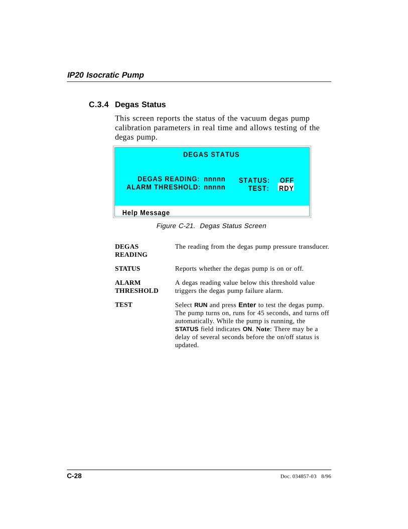
C.3.4 Degas Status
This screen reports the status of the vacuum degas pumpcalibration parameters in real time and allows testing of thedegas pump.
DEGASREADING
The reading from the degas pump pressure transducer.
STATUS Reports whether the degas pump is on or off.
ALARMTHRESHOLD
A degas reading value below this threshold valuetriggers the degas pump failure alarm.
TEST Select RUN and press Enter to test the degas pump.The pump turns on, runs for 45 seconds, and turns offautomatically. While the pump is running, theSTATUS field indicates ON. Note: There may be adelay of several seconds before the on/off status isupdated.
Help Message
DEGAS READING:ALARM THRESHOLD:
DEGAS STATUS
STATUS:
RDY OFF
TEST:nnnnnnnnnn
Figure C-21. Degas Status Screen
IP20 Isocratic Pump
C-28 Doc. 034857-03 8/96
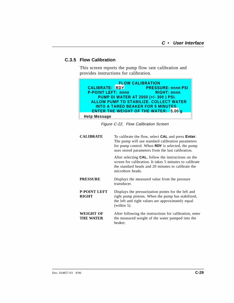
C.3.5 Flow Calibration
This screen reports the pump flow rate calibration andprovides instructions for calibration.
CALIBRATE To calibrate the flow, select CAL and press Enter .The pump will use standard calibration parametersfor pump control. When RDY is selected, the pumpuses stored parameters from the last calibration.
After selecting CAL , follow the instructions on thescreen for calibration. It takes 5 minutes to calibratethe standard heads and 20 minutes to calibrate themicrobore heads.
PRESSURE Displays the measured value from the pressuretransducer.
P-POINT LEFTRIGHT
Displays the pressurization points for the left andright pump pistons. When the pump has stabilized,the left and right values are approximately equal(within 5).
WEIGHT OFTHE WATER
After following the instructions for calibration, enterthe measured weight of the water pumped into thebeaker.
Help Message
PUMP DI WATER AT 2000 (+/- 300 ) PSI.
CALIBRATE: FLOW CALIBRATION
RDYP-POINT LEFT:
PRESSURE: RIGHT:
PSInnnnnnnn nnnn
ALLOW PUMP TO STABILIZE. COLLECT WATERINTO A TARED BEAKER FOR 5 MINUTES.
ENTER THE WEIGHT OF THE WATER: 5.00 g
Figure C-22. Flow Calibration Screen
C • User Interface
Doc. 034857-03 8/96 C-29
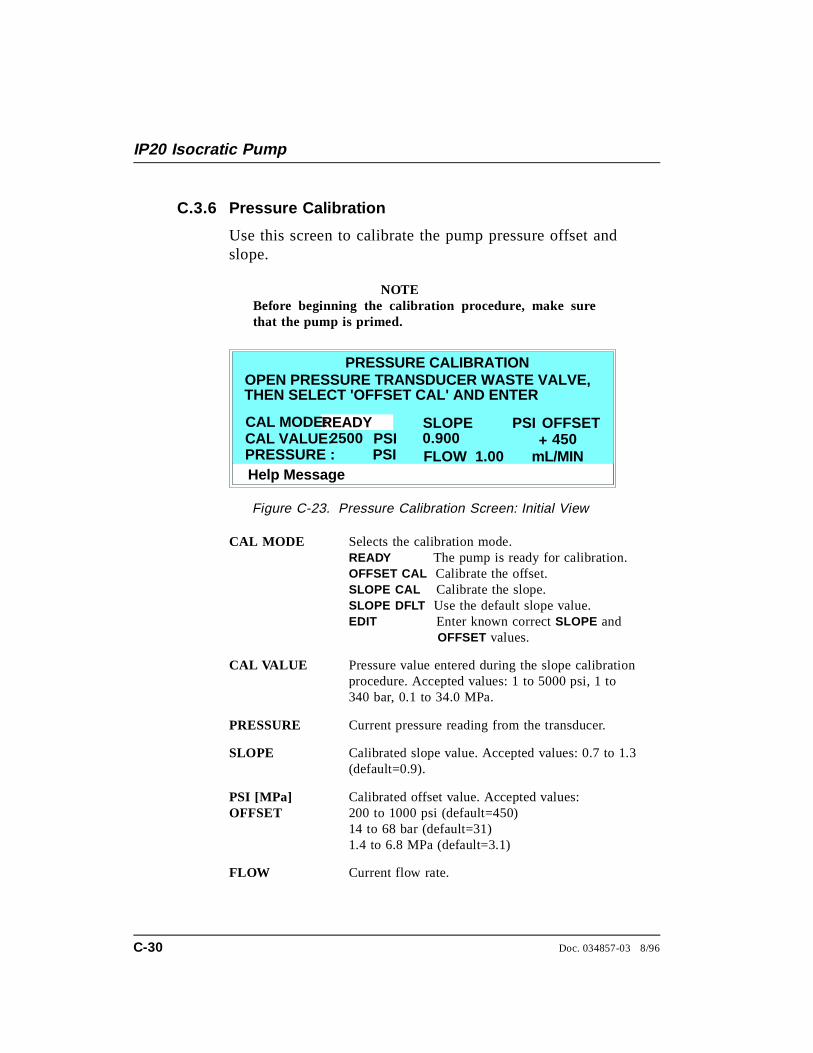
C.3.6 Pressure Calibration
Use this screen to calibrate the pump pressure offset andslope.
NOTEBefore beginning the calibration procedure, make surethat the pump is primed.
CAL MODE Selects the calibration mode. READY The pump is ready for calibration.OFFSET CAL Calibrate the offset.SLOPE CAL Calibrate the slope.SLOPE DFLT Use the default slope value.EDIT Enter known correct SLOPE and OFFSET values.
CAL VALUE Pressure value entered during the slope calibrationprocedure. Accepted values: 1 to 5000 psi, 1 to340 bar, 0.1 to 34.0 MPa.
PRESSURE Current pressure reading from the transducer.
SLOPE Calibrated slope value. Accepted values: 0.7 to 1.3(default=0.9).
PSI [MPa] OFFSET
Calibrated offset value. Accepted values:200 to 1000 psi (default=450)14 to 68 bar (default=31)1.4 to 6.8 MPa (default=3.1)
FLOW Current flow rate.
Help Message
OPEN PRESSURE TRANSDUCER WASTE VALVE,PRESSURE CALIBRATION
THEN SELECT 'OFFSET CAL' AND ENTER
READY SLOPE
PRESSURE :
CAL MODE:
PSI
OFFSET
FLOW 1.00 mL/MIN+
PSI0.900 450CAL VALUE: 2500 PSI
Figure C-23. Pressure Calibration Screen: Initial View
IP20 Isocratic Pump
C-30 Doc. 034857-03 8/96
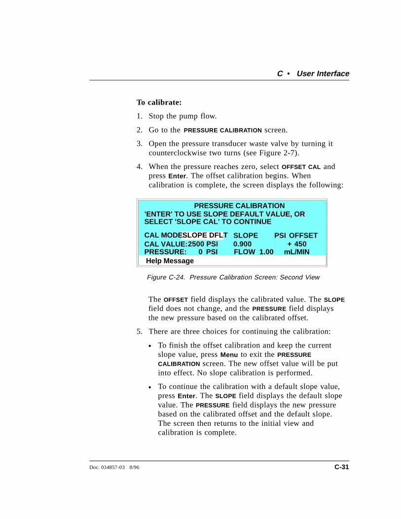
To calibrate:
1. Stop the pump flow.
2. Go to the PRESSURE CALIBRATION screen.
3. Open the pressure transducer waste valve by turning itcounterclockwise two turns (see Figure 2-7).
4. When the pressure reaches zero, select OFFSET CAL andpress Enter . The offset calibration begins. Whencalibration is complete, the screen displays the following:
The OFFSET field displays the calibrated value. The SLOPE
field does not change, and the PRESSURE field displaysthe new pressure based on the calibrated offset.
5. There are three choices for continuing the calibration:
• To finish the offset calibration and keep the currentslope value, press Menu to exit the PRESSURE
CALIBRATION screen. The new offset value will be putinto effect. No slope calibration is performed.
• To continue the calibration with a default slope value,press Enter . The SLOPE field displays the default slopevalue. The PRESSURE field displays the new pressurebased on the calibrated offset and the default slope.The screen then returns to the initial view andcalibration is complete.
Help Message
'ENTER' TO USE SLOPE DEFAULT VALUE, ORPRESSURE CALIBRATION
SELECT 'SLOPE CAL' TO CONTINUE
SLOPE DFLT SLOPE
PRESSURE:
CAL MODE:
PSI
OFFSET
FLOW 1.00 mL/MIN+
PSI0.900 450CAL VALUE: 2500 PSI
0
Figure C-24. Pressure Calibration Screen: Second View
C • User Interface
Doc. 034857-03 8/96 C-31

• To continue to the slope calibration procedure, selectSLOPE CAL in the CAL MODE field and press Enter . Thescreen displays the following:
6. Close the waste valve.
7. Install a pressure test gauge between the pressuretransducer outlet and either a length of backpressuretubing, or a column (see Figure C-26). A pressure gaugeassembly (P/N 046175), which includes a gauge with anaccuracy rating of ±0.25%, and required fittings, isavailable for this purpose. Contact your Dionex office fordetails.
Help Message
CLOSE WASTE VALVE, INSTALL GAUGE.PRESSURE CALIBRATION
TURN PUMP ON AND ENTER GAUGE PRESSURE.
SLOPE CAL SLOPE
PRESSURE :
CAL MODE:
PSI
OFFSET
FLOW 1.00 mL/MIN+
PSI0.900 450CAL VALUE: 2500 PSI
Figure C-25. Pressure Calibration Screen: Third View
Pressure TransducerOutlet
Pressure Test Gau ge
Back p ressureTubin g
Column
or
Figure C-26. Pressure Gauge Installation
IP20 Isocratic Pump
C-32 Doc. 034857-03 8/96
8. In the FLOW field, enter the flow rate normally used foryour application.
9. Turn on the pump. The pressure will begin increasing.Allow the pressure gauge reading to stabilize.
10. This step depends on whether backpressure tubing or acolumn is installed:
• If backpressure tubing is installed, the recommendedpressure for calibration is 17.25 ±0.17 MPa(2500 ±25 psi). If necessary, adjust the flow rate tobring the pressure to the recommended value.Increasing the flow rate increases the pressure;decreasing it decreases the pressure. When the gaugereading has stabilized at the recommended value, enterthe reading in the CAL VALUE field.
• If a column is installed, the application flow rate andthe type of column installed determine the pressure forcalibration. After allowing the gauge pressure tostabilize, enter the reading in the CAL VALUE field.
NOTEThe pressure gauge readings may fluctuate slightly asthe left and right pump heads alternate piston strokes.You can ignore variations of about ±0.03 MPa (±5 psi)or less. Larger fluctuations generally indicate that thepump is out of prime. If this occurs, prime the pumpheads (see Section B.2.7) and then repeat Step 10.
11. Press Enter . The slope calibration begins. Whencalibration is complete, the screen fields display thefollowing:
• The SLOPE field displays the new slope value.
• The PRESSURE field displays the same value as theCAL VALUE .
C • User Interface
Doc. 034857-03 8/96 C-33
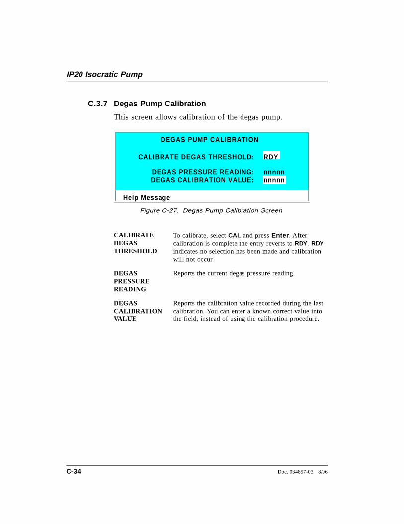
C.3.7 Degas Pump Calibration
This screen allows calibration of the degas pump.
CALIBRATEDEGASTHRESHOLD
To calibrate, select CAL and press Enter . Aftercalibration is complete the entry reverts to RDY. RDYindicates no selection has been made and calibrationwill not occur.
DEGAS PRESSUREREADING
Reports the current degas pressure reading.
DEGAS CALIBRATIONVALUE
Reports the calibration value recorded during the lastcalibration. You can enter a known correct value intothe field, instead of using the calibration procedure.
Help Message
CALIBRATE DEGAS THRESHOLD:
DEGAS PUMP CALIBRATION
nnnnn
RDY
DEGAS PRESSURE READING: DEGAS CALIBRATION VALUE:
nnnnn
Figure C-27. Degas Pump Calibration Screen
IP20 Isocratic Pump
C-34 Doc. 034857-03 8/96
D • TTL and Relay Control
D.1 TTL and Relay Output Operation . . . . . . . . D-4
D.2 TTL Input Operation . . . . . . . . . . . . . . . D-5
D.2.1 TTL Input Signal Modes . . . . . . . . D-5
D.3 TTL and Relay Connections . . . . . . . . . . . D-7
D.3.1 Example Connections . . . . . . . . . . D-8
Doc. 034857-03 8/96 D-1

IP20 Isocratic Pump
D-2 Doc. 034857-03 8/96
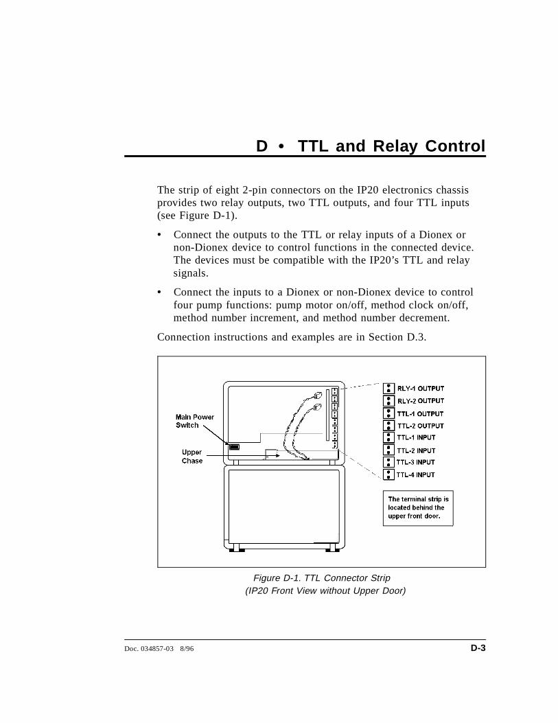
D • TTL and Relay Control
The strip of eight 2-pin connectors on the IP20 electronics chassisprovides two relay outputs, two TTL outputs, and four TTL inputs(see Figure D-1).
• Connect the outputs to the TTL or relay inputs of a Dionex ornon-Dionex device to control functions in the connected device.The devices must be compatible with the IP20’s TTL and relaysignals.
• Connect the inputs to a Dionex or non-Dionex device to controlfour pump functions: pump motor on/off, method clock on/off,method number increment, and method number decrement.
Connection instructions and examples are in Section D.3.
Figure D-1. TTL Connector Strip (IP20 Front View without Upper Door)
Doc. 034857-03 8/96 D-3
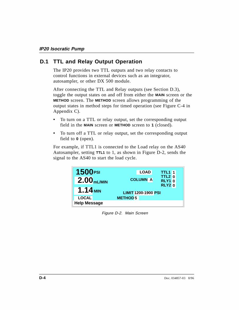
D.1 TTL and Relay Output Operation
The IP20 provides two TTL outputs and two relay contacts tocontrol functions in external devices such as an integrator,autosampler, or other DX 500 module.
After connecting the TTL and Relay outputs (see Section D.3),toggle the output states on and off from either the MAIN screen or theMETHOD screen. The METHOD screen allows programming of theoutput states in method steps for timed operation (see Figure C-4 inAppendix C).
• To turn on a TTL or relay output, set the corresponding outputfield in the MAIN screen or METHOD screen to 1 (closed).
• To turn off a TTL or relay output, set the corresponding outputfield to 0 (open).
For example, if TTL1 is connected to the Load relay on the AS40Autosampler, setting TTL1 to 1, as shown in Figure D-2, sends thesignal to the AS40 to start the load cycle.
Help Message
PSI TTL1TTL2RLY1RLY2
METHOD
1000
COLUMN A
1500 mL/MIN2.00MIN1.14
LOCAL
LOAD
LIMIT51200-1900 PSI
Figure D-2. Main Screen
IP20 Isocratic Pump
D-4 Doc. 034857-03 8/96

D.2 TTL Input Operation
The four TTL inputs can be connected to devices capable ofproviding TTL signals. The signal from the connected devices cancontrol one to four specific functions in the IP20.
• TTL input 1 turns the pump motor off and on.
• TTL input 2 controls the pump method clock. A signal from thecontrolling device can turn the method clock on (Run) and off(Hold/Reset). Hold/Reset resets the method clock to zero andexecutes INIT conditions. The method will not run unless thepump motor is already on.
• TTL input 3 increases the method number by one. Eachadditional signal increases the method number by one more.
When the method clock is zero (or INIT), increasing the methodnumber executes the INIT conditions of the new method. When themethod clock is greater than zero, increasing the method numberbegins running the new method at the current elapsed methodclock time. This has the same result as selecting a new methodnumber when the pump is in Local mode.
• TTL input 4 decreases the method number by one. Theoperation is as described under TTL input 3 above, except thatmethod numbers decrease instead of increase.
D.2.1 TTL Input Signal Modes
The IP20 TTL inputs respond to four types of signals toaccommodate different types of device output signals. Thedefault signal mode, normal edge, is compatible with theoutput signals provided by DX 500 modules. If the deviceconnected to the IP20 outputs a different signal type, select adifferent signal mode from the TIME FUNCTION IN screen (seeFigure D-3).
D • TTL and Relay Control
Doc. 034857-03 8/96 D-5
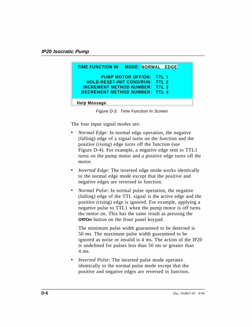
The four input signal modes are:
• Normal Edge: In normal edge operation, the negative(falling) edge of a signal turns on the function and thepositive (rising) edge turns off the function (seeFigure D-4). For example, a negative edge sent to TTL1turns on the pump motor and a positive edge turns off themotor.
• Inverted Edge: The inverted edge mode works identicallyto the normal edge mode except that the positive andnegative edges are reversed in function.
• Normal Pulse: In normal pulse operation, the negative(falling) edge of the TTL signal is the active edge and thepositive (rising) edge is ignored. For example, applying anegative pulse to TTL1 when the pump motor is off turnsthe motor on. This has the same result as pressing theOff/On button on the front panel keypad.
The minimum pulse width guaranteed to be detected is50 ms. The maximum pulse width guaranteed to beignored as noise or invalid is 4 ms. The action of the IP20is undefined for pulses less than 50 ms or greater than4 ms.
• Inverted Pulse: The inverted pulse mode operatesidentically to the normal pulse mode except that thepositive and negative edges are reversed in function.
Help Message
HOLD-RESET-INIT COND/RUN:INCREMENT METHOD NUMBER:
1234
TIME FUNCTION IN
PUMP MOTOR OFF/ON:
MODE: NORMAL EDGE
TTLTTLTTLTTLDECREMENT METHOD NUMBER:
Figure D-3. Time Function In Screen
IP20 Isocratic Pump
D-6 Doc. 034857-03 8/96
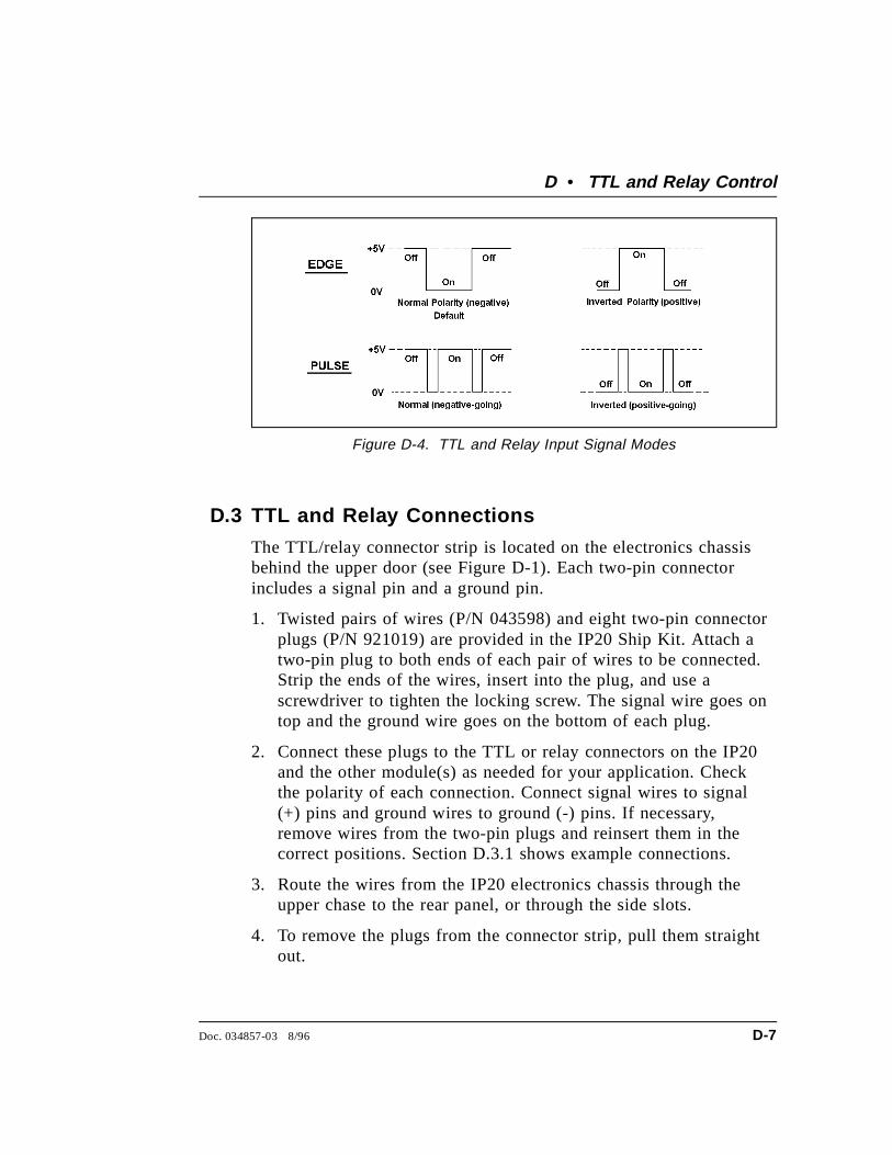
D.3 TTL and Relay Connections
The TTL/relay connector strip is located on the electronics chassisbehind the upper door (see Figure D-1). Each two-pin connectorincludes a signal pin and a ground pin.
1. Twisted pairs of wires (P/N 043598) and eight two-pin connectorplugs (P/N 921019) are provided in the IP20 Ship Kit. Attach atwo-pin plug to both ends of each pair of wires to be connected.Strip the ends of the wires, insert into the plug, and use ascrewdriver to tighten the locking screw. The signal wire goes ontop and the ground wire goes on the bottom of each plug.
2. Connect these plugs to the TTL or relay connectors on the IP20and the other module(s) as needed for your application. Checkthe polarity of each connection. Connect signal wires to signal(+) pins and ground wires to ground (-) pins. If necessary,remove wires from the two-pin plugs and reinsert them in thecorrect positions. Section D.3.1 shows example connections.
3. Route the wires from the IP20 electronics chassis through theupper chase to the rear panel, or through the side slots.
4. To remove the plugs from the connector strip, pull them straightout.
Figure D-4. TTL and Relay Input Signal Modes
D • TTL and Relay Control
Doc. 034857-03 8/96 D-7

D.3.1 Example Connections
Figure D-5 shows an example of TTL/relay connections for aDX 500 system connected to an AS40 Automated Sampler.Refer to the AS40 operator’s manual for details.
RE
AD
Y O
UT
AS40
RLY-1OUTRLY-2OUTTTL-1OUTTTL-2OUTTTL-1INTTL-2INTTL-3INTTL-4IN
RLY-1OUTRLY-2OUTTTL-1OUTTTL-2OUTTTL-1INTTL-2INTTL-3INTTL-4IN1 2 3 4 5
RELAY CONTROL
GN
DF
2 GN
DLO
AD
GN
DC
BL
PR
ES
EN
TG
ND
+5V
DC
<50
mA
GN
D
AS40 Relay Control Cable (P/N 047946)
PeakNet Chromatography Workstation
DX-LAN
LOAD
READY
Pump Detector
Figure D-5. Example TTL and Relay Connections: AS40
IP20 Isocratic Pump
D-8 Doc. 034857-03 8/96
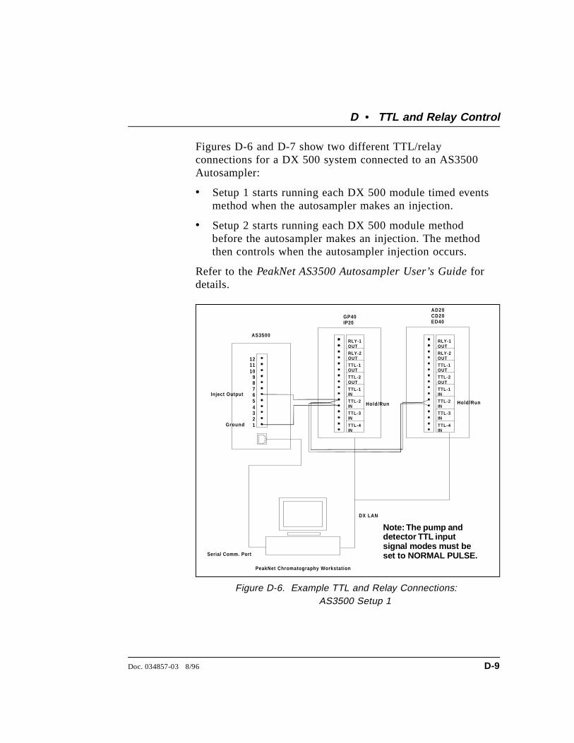
Figures D-6 and D-7 show two different TTL/relayconnections for a DX 500 system connected to an AS3500Autosampler:
• Setup 1 starts running each DX 500 module timed eventsmethod when the autosampler makes an injection.
• Setup 2 starts running each DX 500 module methodbefore the autosampler makes an injection. The methodthen controls when the autosampler injection occurs.
Refer to the PeakNet AS3500 Autosampler User’s Guide fordetails.
AS3500
GP40IP20
AD20CD20ED40
RLY-1OUT
RLY-2OUT
TTL-1OUT
TTL-2OUT
TTL-1IN
TTL-2IN
TTL-3IN
TTL-4IN
RLY-1OUT
RLY-2OUT
TTL-1OUT
TTL-2OUT
TTL-1IN
TTL-2IN
TTL-3IN
TTL-4IN
12345
PeakNet Chromatography Workstation
DX LAN
6789
101112
Inject Output
Ground
Serial Comm. Port
Hold/Run Hold/Run
Note: The pump and detectormust be set to NORMAL PULSE TTL input signal mode.
Note: The pump anddetector TTL inputsignal modes must beset to NORMAL PULSE.
Figure D-6. Example TTL and Relay Connections: AS3500 Setup 1
D • TTL and Relay Control
Doc. 034857-03 8/96 D-9
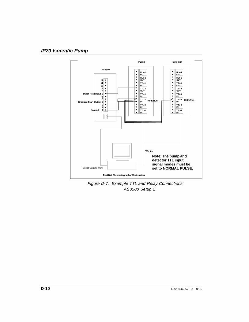
AS3500
Pump Detector
RLY-1OUT
RLY-2OUT
TTL-1OUT
TTL-2OUT
TTL-1IN
TTL-2IN
TTL-3IN
TTL-4IN
RLY-1OUT
RLY-2OUT
TTL-1OUT
TTL-2OUT
TTL-1IN
TTL-2IN
TTL-3IN
TTL-4IN
12345
PeakNet Chromatography Workstation
DX-LAN
6789
101112
Note: The pump and detectorTTL input signal modes must beset to NORMAL PULSE.
Ground
Serial Comm. Port
Hold/Run Hold/RunGradient Start Output
Inject Hold Input
Note: The pump anddetector TTL inputsignal modes must beset to NORMAL PULSE.
Figure D-7. Example TTL and Relay Connections: AS3500 Setup 2
IP20 Isocratic Pump
D-10 Doc. 034857-03 8/96

Figure D-8 shows an example of TTL/relay connections foran LC30 Chromatography Oven. Refer to the LC30 manualfor details.
FAULT OUT
ERROROUT
READYOUT
ACTIVE/STANDBY
LC30
GP40IP20
AD20CD20ED40
RLY-1OUT
RLY-2OUT
TTL-1OUT
TTL-2OUT
TTL-1IN
TTL-2IN
TTL-3IN
TTL-4IN
RLY-1OUT
RLY-2OUT
TTL-1OUT
TTL-2OUT
TTL-1IN
TTL-2IN
TTL-3IN
TTL-4IN
Figure D-8. Example TTL and Relay Connections: LC30
D • TTL and Relay Control
Doc. 034857-03 8/96 D-11

IP20 Isocratic Pump
D-12 Doc. 034857-03 8/96
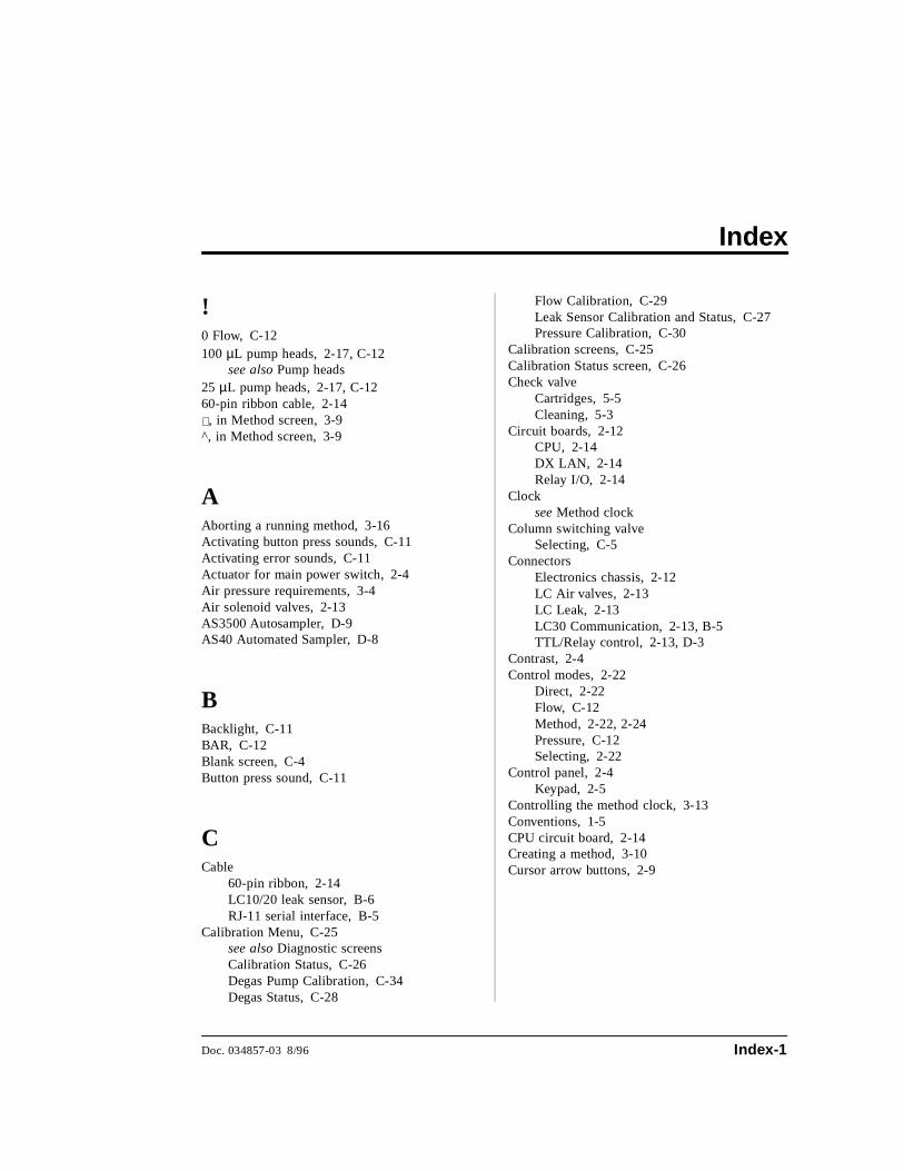
Index
!0 Flow, C-12100 µL pump heads, 2-17, C-12
see also Pump heads25 µL pump heads, 2-17, C-1260-pin ribbon cable, 2-14∨, in Method screen, 3-9^, in Method screen, 3-9
AAborting a running method, 3-16Activating button press sounds, C-11Activating error sounds, C-11Actuator for main power switch, 2-4Air pressure requirements, 3-4Air solenoid valves, 2-13AS3500 Autosampler, D-9AS40 Automated Sampler, D-8
BBacklight, C-11BAR, C-12Blank screen, C-4Button press sound, C-11
CCable
60-pin ribbon, 2-14LC10/20 leak sensor, B-6RJ-11 serial interface, B-5
Calibration Menu, C-25see also Diagnostic screensCalibration Status, C-26Degas Pump Calibration, C-34Degas Status, C-28
Flow Calibration, C-29Leak Sensor Calibration and Status, C-27Pressure Calibration, C-30
Calibration screens, C-25Calibration Status screen, C-26Check valve
Cartridges, 5-5Cleaning, 5-3
Circuit boards, 2-12CPU, 2-14DX LAN, 2-14Relay I/O, 2-14
Clocksee Method clock
Column switching valveSelecting, C-5
ConnectorsElectronics chassis, 2-12LC Air valves, 2-13LC Leak, 2-13LC30 Communication, 2-13, B-5TTL/Relay control, 2-13, D-3
Contrast, 2-4Control modes, 2-22
Direct, 2-22Flow, C-12Method, 2-22, 2-24Pressure, C-12Selecting, 2-22
Control panel, 2-4Keypad, 2-5
Controlling the method clock, 3-13Conventions, 1-5CPU circuit board, 2-14Creating a method, 3-10Cursor arrow buttons, 2-9
Doc. 034857-03 8/96 Index-1
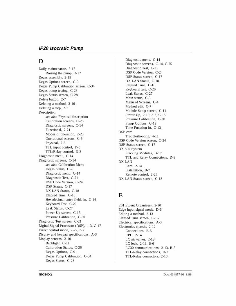
DDaily maintenance, 3-17
Rinsing the pump, 3-17Degas assembly, 2-19Degas Options screen, C-9Degas Pump Calibration screen, C-34Degas pump testing, C-28Degas Status screen, C-28Delete button, 2-7Deleting a method, 3-16Deleting a step, 2-7Description
see also Physical descriptionCalibration screens, C-25Diagnostic screens, C-14Functional, 2-21Modes of operation, 2-23Operational screens, C-5Physical, 2-3TTL input control, D-5TTL/Relay control, D-3
Diagnostic menu, C-14Diagnostic screens, C-14
see also Calibration MenuDegas Status, C-28Diagnostic menu, C-14Diagnostic Test, C-21DSP Code Version, C-24DSP Status, C-17DX LAN Status, C-18Elapsed Time, C-16Hexadecimal entry fields in, C-14Keyboard Test, C-20Leak Status, C-27Power-Up screen, C-15Pressure Calibration, C-30
Diagnostic Test screen, C-21Digital Signal Processor (DSP), 1-3, C-17Direct control mode, 2-22, 3-7Display and keypad specifications, A-3Display screens, 2-10
Backlight, C-11Calibration Status, C-26Degas Options, C-9Degas Pump Calibration, C-34Degas Status, C-28
Diagnostic menu, C-14Diagnostic screens, C-14, C-25Diagnostic Test, C-21DSP Code Version, C-24DSP Status screen, C-17DX LAN Status, C-18Elapsed Time, C-16Keyboard test, C-20Leak Status, C-27Main status, C-5Menu of Screens, C-4Method edit, C-7Module Setup screen, C-11Power-Up, 2-10, 3-5, C-15Pressure Calibration, C-30Pump Options, C-12Time Function In, C-13
DSP cardTroubleshooting, 4-11
DSP Code Version screen, C-24DSP Status screen, C-17DX 500 System
Stacking Modules, B-17TTL and Relay Connections, D-8
DX LANCard, 2-14Installation, B-7Remote control, 2-23
DX LAN Status screen, C-18
E
E01 Eluent Organizers, 2-20Edge input signal mode, D-6Editing a method, 3-13Elapsed Time screen, C-16Electrical specifications, A-3Electronics chassis, 2-12
Connections, B-5CPU, 2-14LC air valves, 2-13LC leak, 2-13, B-6LC30 communications, 2-13, B-5TTL/Relay connections, D-7TTL/Relay connectors, 2-13
IP20 Isocratic Pump
Index-2 Doc. 034857-03 8/96
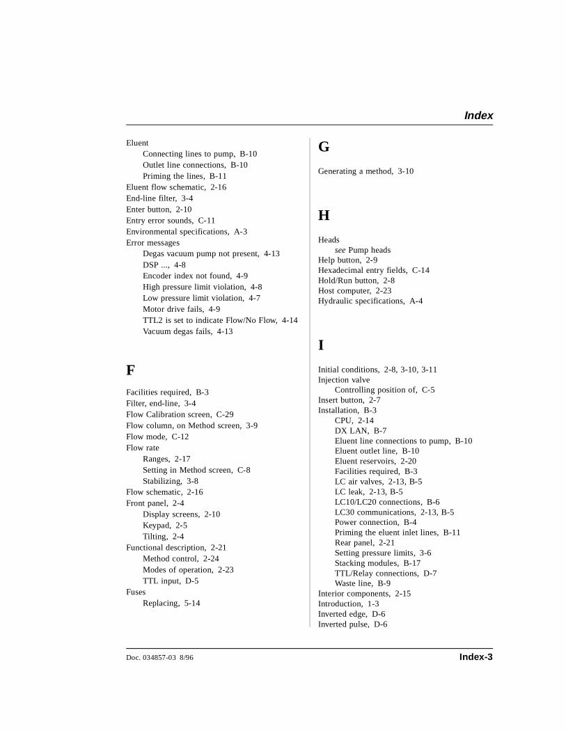
EluentConnecting lines to pump, B-10Outlet line connections, B-10Priming the lines, B-11
Eluent flow schematic, 2-16End-line filter, 3-4Enter button, 2-10Entry error sounds, C-11Environmental specifications, A-3Error messages
Degas vacuum pump not present, 4-13DSP ..., 4-8Encoder index not found, 4-9High pressure limit violation, 4-8Low pressure limit violation, 4-7Motor drive fails, 4-9TTL2 is set to indicate Flow/No Flow, 4-14Vacuum degas fails, 4-13
FFacilities required, B-3Filter, end-line, 3-4Flow Calibration screen, C-29Flow column, on Method screen, 3-9Flow mode, C-12Flow rate
Ranges, 2-17Setting in Method screen, C-8Stabilizing, 3-8
Flow schematic, 2-16Front panel, 2-4
Display screens, 2-10Keypad, 2-5Tilting, 2-4
Functional description, 2-21Method control, 2-24Modes of operation, 2-23TTL input, D-5
FusesReplacing, 5-14
G
Generating a method, 3-10
H
Headssee Pump heads
Help button, 2-9Hexadecimal entry fields, C-14Hold/Run button, 2-8Host computer, 2-23Hydraulic specifications, A-4
I
Initial conditions, 2-8, 3-10, 3-11Injection valve
Controlling position of, C-5Insert button, 2-7Installation, B-3
CPU, 2-14DX LAN, B-7Eluent line connections to pump, B-10Eluent outlet line, B-10Eluent reservoirs, 2-20Facilities required, B-3LC air valves, 2-13, B-5LC leak, 2-13, B-5LC10/LC20 connections, B-6LC30 communications, 2-13, B-5Power connection, B-4Priming the eluent inlet lines, B-11Rear panel, 2-21Setting pressure limits, 3-6Stacking modules, B-17TTL/Relay connections, D-7Waste line, B-9
Interior components, 2-15Introduction, 1-3Inverted edge, D-6Inverted pulse, D-6
Index
Doc. 034857-03 8/96 Index-3

K
Keyboard Test screen, C-20Keypad buttons, 2-5
Button press sound, C-11Cursor arrows, 2-9Delete, 2-7Enter, 2-10Help, 2-9Hold/Run, 2-8Insert, 2-7Menu, 2-9Numerical buttons, 2-10Off/On, 2-6Prime, 2-6Reset, 2-8Select, 2-8
L
LC air valves, 2-13LC leak, 2-13, B-5LC10/LC20 connections, B-6LC30 communications, 2-13, B-5Leak alarm, 4-9Leak sensor calibration, C-27Leak status screen, C-27LED
Power supply status, 2-14Left/right pressurization points, C-24Limit field
Method screen, C-7Selecting pressure limits, 3-6
Liquid crystal display (LCD)Adjusting the screen contrast, 2-4
Liquid leaks, 4-9Liquid lines
PEEK, 5-4Stainless steel, 5-4
Local mode, 2-21, 2-23, C-5Locked Remote mode, 2-24
MMain status screen, C-5Maintenance
Daily, 3-17Periodic, 3-19Replacing piston seals, 3-19Rinsing the pump, 3-17Routine maintenance, 3-17
Manuals, 1-7Mechanical chassis, 2-15Menu button, 2-9Menu of Screens, C-4Menu structure chart, C-3Method clock, 2-25
Controlling, 3-13Controlling with TTL input, D-5Holding (pausing), 2-8Resetting, 2-8Starting a method, 3-13
Method control, 2-22, 3-8Method edit screen, C-7Method steps
Definition, 2-25Deleting, 3-14Entering, 3-8, C-7Inserting, 3-11Maximum number allowed, 2-25Setting step times, C-7
MethodsAborting a running method, 3-16Control, 3-8Creating, 3-10Deleting a method, 3-16Deleting a step, 2-7, 3-14Editing, 3-13INIT conditions, 3-10Inserting a step, 2-7Number allowed, 2-25Running a method, 3-12
Microbore heads, 2-17see also Pump heads
MIN, C-6mL/MIN, C-6Modes of operation
see Operating modesModule Setup screen, C-11
IP20 Isocratic Pump
Index-4 Doc. 034857-03 8/96
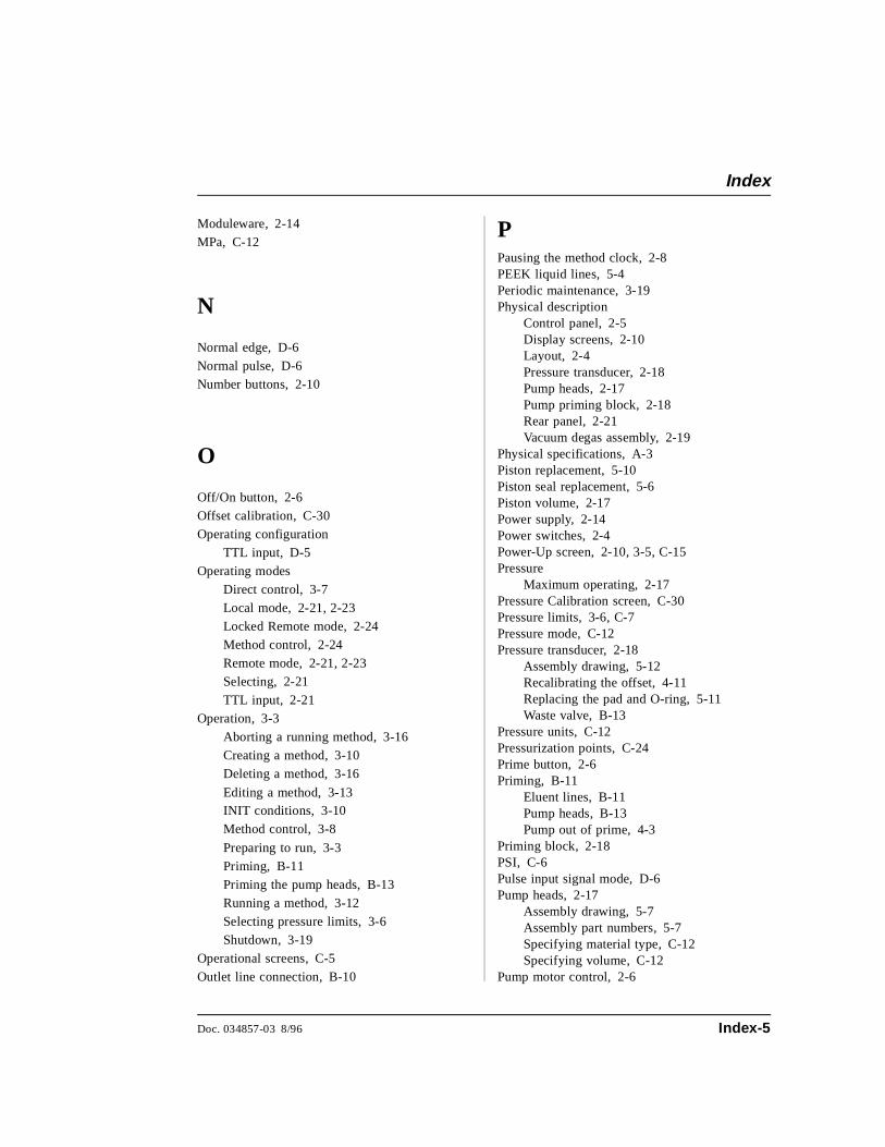
Moduleware, 2-14MPa, C-12
N
Normal edge, D-6Normal pulse, D-6Number buttons, 2-10
O
Off/On button, 2-6Offset calibration, C-30Operating configuration
TTL input, D-5Operating modes
Direct control, 3-7Local mode, 2-21, 2-23Locked Remote mode, 2-24Method control, 2-24Remote mode, 2-21, 2-23Selecting, 2-21TTL input, 2-21
Operation, 3-3Aborting a running method, 3-16Creating a method, 3-10Deleting a method, 3-16
Editing a method, 3-13INIT conditions, 3-10Method control, 3-8
Preparing to run, 3-3Priming, B-11Priming the pump heads, B-13Running a method, 3-12Selecting pressure limits, 3-6Shutdown, 3-19
Operational screens, C-5Outlet line connection, B-10
PPausing the method clock, 2-8PEEK liquid lines, 5-4Periodic maintenance, 3-19Physical description
Control panel, 2-5Display screens, 2-10Layout, 2-4Pressure transducer, 2-18Pump heads, 2-17Pump priming block, 2-18Rear panel, 2-21Vacuum degas assembly, 2-19
Physical specifications, A-3Piston replacement, 5-10Piston seal replacement, 5-6Piston volume, 2-17Power supply, 2-14Power switches, 2-4Power-Up screen, 2-10, 3-5, C-15Pressure
Maximum operating, 2-17Pressure Calibration screen, C-30Pressure limits, 3-6, C-7Pressure mode, C-12Pressure transducer, 2-18
Assembly drawing, 5-12Recalibrating the offset, 4-11Replacing the pad and O-ring, 5-11Waste valve, B-13
Pressure units, C-12Pressurization points, C-24Prime button, 2-6Priming, B-11
Eluent lines, B-11Pump heads, B-13Pump out of prime, 4-3
Priming block, 2-18PSI, C-6Pulse input signal mode, D-6Pump heads, 2-17
Assembly drawing, 5-7Assembly part numbers, 5-7Specifying material type, C-12Specifying volume, C-12
Pump motor control, 2-6
Index
Doc. 034857-03 8/96 Index-5
Pump Options screen, B-15, C-12Pump priming block, 2-18
RRear panel, 2-21Relay connectors, 2-13
see also TTL/Relay controlRelief valve, B-13Remote mode, 2-23, C-5Reset button, 2-8Rinsing the pump heads, 3-17Routine maintenance, 3-17Running a method, 3-12
SSafety messages, 1-5Save To field
Method screen, C-7Screen brightness, C-11Screen contrast, 2-4Screens
see Display screensSeal replacement, 5-6Securing modules, B-18Select buttons, 2-8Self-Regenerating Suppressor (SRS)
Automatic shut off, B-15Service, 5-3
Check valves, 5-3Fuses, 5-14Piston seal, 5-6Pressure transducer O-ring, 5-11Pressure transducer pad, 5-11Pump piston, 5-10Waste valve O-ring, 5-13
Setting pressure limits, 3-6Setting step times, C-7Shoe installation, B-18Shutdown, 3-19Signal modes for TTL input, D-5Solenoid valves
Connecting to the LC10/20/30, 2-13, B-6
SpecificationsDisplay and keypad, A-3Electrical, A-3Environmental, A-3Hydraulic, A-4Physical, A-3Vacuum degas assembly, A-5
SRSAutomatic shut off, B-15
Stabilizing the flow rate, 3-8Stacking modules, B-17Stainless steel liquid lines, 5-4Standard bore heads, 2-17
see also Pump headsSystem outlet line, B-10
T
TestsDiagnostic, C-21Keyboard, C-20Pressure transducer, C-23Vacuum degas pump, C-28
Tie installation, B-19Tilting the front panel, 2-4Time
Pump, seals, backlight in use, C-16Setting the clock, 3-13
Time fieldMethod screen, C-7
Time Function In screen, C-13, D-5Time-based steps, entering, 3-8Transducer, 2-18Troubleshooting, 4-3
Chromatographic reproducibility, 4-15Degas vacuum pump calibration, 4-13Leak alarm, 4-9Liquid leaks, 4-9Noisy pump motor, 4-11Pump head pressure fluctuations, 4-3Pump out of prime, 4-3Pump stops, 4-6Pump will not start, 4-6Relay control functions, 4-14
IP20 Isocratic Pump
Index-6 Doc. 034857-03 8/96
TTL/Relay control, 2-21, D-3Connectors, 2-13, D-3Example connections, D-8Input operation, D-5Input signal modes, D-5Installation, D-7Output operation, D-4Setting outputs, C-6, C-8
TTL2 output usage, B-15, C-12Type of control, 2-24
Method control, 2-24
U
User interface screenssee Display screens
V
V (valve) column on Method screen, 3-8, C-8
Vacuum degas assembly, 2-19
Vacuum degas assembly specifications, A-5Valves
Check valves, 5-3
Column switching, C-5Injection, C-5
W
Waste line installation, B-9Waste valve, B-13
Index
Doc. 034857-03 8/96 Index-7

IP20 Isocratic Pump
Index-8 Doc. 034857-03 8/96