ip office - shall not be responsible for any modifications, additions, or deletions ... ip office...
TRANSCRIPT
15-601047 EN-S Issue 04c – (19 April 2012)
DECT R4 Installation
IP Office

DECT R4 Installation Page 215-601047 EN-S Issue 04c (19 April 2012)IP Office
© 2012 AVAYA All Rights Reserved.
NoticesWhile reasonable efforts have been made to ensure that the information inthis document is complete and accurate at the time of printing, Avayaassumes no liability for any errors. Avaya reserves the right to make changesand corrections to the information in this document without the obligation tonotify any person or organization of such changes.
Documentation disclaimerAvaya shall not be responsible for any modifications, additions, or deletionsto the original published version of this documentation unless suchmodifications, additions, or deletions were performed by Avaya.
End User agree to indemnify and hold harmless Avaya, Avaya's agents,servants and employees against all claims, lawsuits, demands and judgmentsarising out of, or in connection with, subsequent modifications, additions ordeletions to this documentation, to the extent made by End User.
Link disclaimerAvaya is not responsible for the contents or reliability of any linked Web sitesreferenced within this site or documentation(s) provided by Avaya. Avaya isnot responsible for the accuracy of any information, statement or contentprovided on these sites and does not necessarily endorse the products,services, or information described or offered within them. Avaya does notguarantee that these links will work all the time and has no control over theavailability of the linked pages.
WarrantyAvaya provides a limited warranty on this product. Refer to your salesagreement to establish the terms of the limited warranty. In addition, Avaya’sstandard warranty language, as well as information regarding support for thisproduct, while under warranty, is available to Avaya customers and otherparties through the Avaya Support Web site: http://www.avaya.com/support.Please note that if you acquired the product from an authorized Avaya reselleroutside of the United States and Canada, the warranty is provided to you bysaid Avaya reseller and not by Avaya.
LicensesTHE SOFTWARE LICENSE TERMS AVAILABLE ON THE AVAYA WEBSITE,HTTP://SUPPORT.AVAYA.COM/LICENSEINFO/ ARE APPLICABLE TO ANYONEWHO DOWNLOADS, USES AND/OR INSTALLS AVAYA SOFTWARE,PURCHASED FROM AVAYA INC., ANY AVAYA AFFILIATE, OR AN AUTHORIZEDAVAYA RESELLER (AS APPLICABLE) UNDER A COMMERCIAL AGREEMENTWITH AVAYA OR AN AUTHORIZED AVAYA RESELLER. UNLESS OTHERWISEAGREED TO BY AVAYA IN WRITING, AVAYA DOES NOT EXTEND THISLICENSE IF THE SOFTWARE WAS OBTAINED FROM ANYONE OTHER THANAVAYA, AN AVAYA AFFILIATE OR AN AVAYA AUTHORIZED RESELLER, ANDAVAYA RESERVES THE RIGHT TO TAKE LEGAL ACTION AGAINST YOU ANDANYONE ELSE USING OR SELLING THE SOFTWARE WITHOUT A LICENSE. BYINSTALLING, DOWNLOADING OR USING THE SOFTWARE, OR AUTHORIZINGOTHERS TO DO SO, YOU, ON BEHALF OF YOURSELF AND THE ENTITY FORWHOM YOU ARE INSTALLING, DOWNLOADING OR USING THE SOFTWARE(HEREINAFTER REFERRED TO INTERCHANGEABLY AS “YOU” AND “ENDUSER”), AGREE TO THESE TERMS AND CONDITIONS AND CREATE ABINDING CONTRACT BETWEEN YOU AND AVAYA INC. OR THE APPLICABLEAVAYA AFFILIATE (“AVAYA”).
Avaya grants End User a license within the scope of the license typesdescribed below. The applicable number of licenses and units of capacity forwhich the license is granted will be one (1), unless a different number oflicenses or units of capacity is specified in the Documentation or othermaterials available to End User. "Designated Processor" means a singlestand-alone computing device. "Server" means a Designated Processor thathosts a software application to be accessed by multiple users. "Software"means the computer programs in object code, originally licensed by Avayaand ultimately utilized by End User, whether as stand-alone products orpre-installed on Hardware. "Hardware" means the standard hardwareoriginally sold by Avaya and ultimately utilized by End User.
License typesDesignated System(s) License (DS). End User may install and use each copyof the Software on only one Designated Processor, unless a different numberof Designated Processors is indicated in the Documentation or other materialsavailable to End User. Avaya may require the Designated Processor(s) to beidentified by type, serial number, feature key, location or other specificdesignation, or to be provided by End User to Avaya through electronic meansestablished by Avaya specifically for this purpose.
CopyrightExcept where expressly stated otherwise, no use should be made of materialson this site, the Documentation(s) and Product(s) provided by Avaya. Allcontent on this site, the documentation(s) and the product(s) provided byAvaya including the selection, arrangement and design of the content isowned either by Avaya or its licensors and is protected by copyright and otherintellectual property laws including the sui generis rights relating to theprotection of databases. You may not modify, copy, reproduce, republish,upload, post, transmit or distribute in any way any content, in whole or inpart, including any code and software. Unauthorized reproduction,transmission, dissemination, storage, and or use without the express writtenconsent of Avaya can be a criminal, as well as a civil, offense under theapplicable law.
Third Party Components Certain software programs or portions thereof included in the Product maycontain software distributed under third party agreements ("Third PartyComponents"), which may contain terms that expand or limit rights to usecertain portions of the Product ("Third Party Terms"). Information regardingdistributed Linux OS source code (for those Products that have distributed theLinux OS source code), and identifying the copyright holders of the ThirdParty Components and the Third Party Terms that apply to them is availableon the Avaya Support Web site: http://support.avaya.com/Copyright.
Preventing toll fraud"Toll fraud" is the unauthorized use of your telecommunications system by anunauthorized party (for example, a person who is not a corporate employee,agent, subcontractor, or is not working on your company's behalf). Be awarethat there can be a risk of toll fraud associated with your system and that, iftoll fraud occurs, it can result in substantial additional charges for yourtelecommunications services.
Avaya fraud interventionIf you suspect that you are being victimized by toll fraud and you needtechnical assistance or support, call Technical Service Center Toll FraudIntervention Hotline at +1-800-643-2353 for the United States and Canada.For additional support telephone numbers, see the Avaya Support Web site:http://support.avaya.comSuspected security vulnerabilities with Avaya products should be reported toAvaya by sending mail to: [email protected].
TrademarksAvaya and Aura are trademarks of Avaya, Inc.The trademarks, logos and service marks (“Marks”) displayed in this site, thedocumentation(s) and product(s) provided by Avaya are the registered orunregistered Marks of Avaya, its affiliates, or other third parties. Users arenot permitted to use such Marks without prior written consent from Avaya orsuch third party which may own the Mark. Nothing contained in this site, thedocumentation(s) and product(s) should be construed as granting, byimplication, estoppel, or otherwise, any license or right in and to the Markswithout the express written permission of Avaya or the applicable third party.Avaya is a registered trademark of Avaya Inc. All non-Avaya trademarks arethe property of their respective owners.
Downloading documentsFor the most current versions of documentation, see the Avaya Support Website: http://www.avaya.com/support
Contact Avaya SupportAvaya provides a telephone number for you to use to report problems or toask questions about your product. The support telephone number is1-800-242-2121 in the United States. For additional support telephonenumbers, see the Avaya Web site: http://www.avaya.com/support

DECT R4 Installation Page 315-601047 EN-S Issue 04c (19 April 2012)IP Office
Contents
ContentsDECT R41.
..................................................................... 81.1 Changes in IP Office Release 8.0
..................................................................... 91.2 Changes in IP Office Release 7.0
..................................................................... 101.3 Base Stations
..................................................................... 131.4 Aerials
..................................................................... 141.5 IP DECT Gateway
..................................................................... 151.6 Phones
............................................................................ 151.6.1 3720
............................................................................ 161.6.2 3725
............................................................................ 171.6.3 3740
............................................................................ 181.6.4 3749
..................................................................... 191.7 Chargers
..................................................................... 201.8 AIWS
............................................................................ 211.8.1 AIWS2
............................................................................ 221.8.2 AIWS1
Site Survey and Planning2...................................................................... 252.1 Factors to Consider
..................................................................... 262.2 Handover
..................................................................... 272.3 Base Station Synchronization
..................................................................... 282.4 Performing a Survey
Provisioned Installation3...................................................................... 343.1 DECT Software
..................................................................... 353.2 IP Office Configuration
............................................................................ 363.2.1 Security Settings
............................................................................ 383.2.2 IP DECT Line Setup
............................................................................ 413.2.3 Adding Licenses
............................................................................ 433.2.4 Manually Creating Extensions
..................................................................... 443.3 Master Base Station Setup
............................................................................ 443.3.1 Defaulting the Base Station
............................................................................ 443.3.2 Determining the Base Station IP Address
............................................................................ 453.3.3 Access the Base Station Configuration
............................................................................ 463.3.4 Set the Base Station IP Address
............................................................................ 473.3.5 Update the Base Station Software
............................................................................ 493.3.6 Select Simplified Administration
............................................................................ 503.3.7 Set the DECT Password
............................................................................ 503.3.8 Select Master Mode
............................................................................ 523.3.9 Accept Devices
............................................................................ 533.3.10 Enable Provisioning
............................................................................ 543.3.11 Phonebook Integration
..................................................................... 543.4 IP Slave Base Station Setup
............................................................................ 553.4.1 Defaulting the Base Station
............................................................................ 553.4.2 Determining the Base Station IP Address
............................................................................ 563.4.3 Access the Base Station Configuration
............................................................................ 573.4.4 Set the Base Station IP Address
............................................................................ 583.4.5 Update the Base Station Software
............................................................................ 603.4.6 Register the Slave Base Station
..................................................................... 613.5 Base Station Mounting
..................................................................... 633.6 Phone Subscription
............................................................................ 643.6.1 Install Windows Device Manager
............................................................................ 653.6.2 Loading Parameter Definition Files
............................................................................ 683.6.3 Enabling Subscription
............................................................................ 693.6.4 Manually Creating Extensions
............................................................................ 703.6.5 Subscribing a Phone
............................................................................ 733.6.6 Upgrading Phones
............................................................................ 753.6.7 Disabling Subscription
............................................................................ 763.6.8 Displaying Subscribed Users
............................................................................ 773.6.9 Unsubscribing Phones
IP DECT Gateway Installation4...................................................................... 814.1 Digital Base Station Power Consumption
..................................................................... 824.2 Installing the Digital Base Stations
IP Office User Features5...................................................................... 865.1 Status Indicators
..................................................................... 875.2 Call Services
..................................................................... 895.3 In Call Options
..................................................................... 905.4 Call Waiting Options
Device Management6...................................................................... 936.1 Installing Windows Device Manager
..................................................................... 956.2 Starting AIWS Device Manager
..................................................................... 956.3 Starting Windows Device Manager
..................................................................... 966.4 Load Parameter Definition Files
..................................................................... 986.5 Loading Phone Templates into Device Manager
..................................................................... 1006.6 Applying Templates to Phones
..................................................................... 1026.7 Editing Templates
..................................................................... 1046.8 Upgrading Phone Software
AIWS Installation7...................................................................... 1087.1 AIWS2 Installation
............................................................................ 1087.1.1 AIWS2
............................................................................ 1097.1.2 Browse to the AIWS2
............................................................................ 1107.1.3 Run the Setup Wizard
............................................................................ 1167.1.4 Enable Base Station/AIWS Connection
............................................................................ 1177.1.5 Upgrade the AIWS Firmware
............................................................................ 1227.1.6 AIWS2 Status Lamps
..................................................................... 1227.2 AIWS1 Installation
............................................................................ 1247.2.1 Removing the AIWS Cover
............................................................................ 1257.2.2 Connect the RTC Battery
............................................................................ 1257.2.3 Cable Connections
............................................................................ 1267.2.4 Browse the AIWS
............................................................................ 1277.2.5 Run the Setup Wizard
............................................................................ 1337.2.6 Enable Base Station/AIWS Connection
............................................................................ 1347.2.7 Upgrade the AIWS Firmware
............................................................................ 1397.2.8 Switching Off the AIWS
............................................................................ 1397.2.9 Wall Mount the AIWS
............................................................................ 1407.2.10 Replace the AIWS Cover
............................................................................ 1407.2.11 AIWS Status Lamp
............................................................................ 1417.2.12 Image Installation Mode
Miscellaneous8...................................................................... 1448.1 Reset /Restart Switch
..................................................................... 1448.2 Base Station Status Lamps
..................................................................... 1468.3 IP DECT Gateway Status Lamps
..................................................................... 1478.4 AIWS2 Status Lamps
..................................................................... 1488.5 AIWS1 Status Lamp
Non-Provisioned Installation9...................................................................... 1549.1 DECT Software
..................................................................... 1559.2 Adding Licenses
............................................................................ 1559.2.1 Checking the Licensing Number
............................................................................ 1559.2.2 Adding Licenses
............................................................................ 1569.2.3 Reserving Licenses
DECT R4 Installation Page 415-601047 EN-S Issue 04c (19 April 2012)IP Office
..................................................................... 1579.3 IP DECT Line Setup
..................................................................... 1599.4 Master Base Station Configuration
............................................................................ 1619.4.1 Default the Base Station
............................................................................ 1629.4.2 Access the Base Station's Configuration
............................................................................ 1639.4.3 Update the Base Station Firmware
............................................................................ 1659.4.4 Set the Base Station IP Address
............................................................................ 1669.4.5 Set the Time Source
............................................................................ 1679.4.6 QoS/ToS Settings
............................................................................ 1679.4.7 Enable Status Logging
............................................................................ 1689.4.8 Set the Base Station as the Master
............................................................................ 1709.4.9 Enable Supplementary Services
............................................................................ 1709.4.10 Set the PBX Switch Mode
............................................................................ 1719.4.11 IP Trunk Configuration
............................................................................ 1729.4.12 Enter the Radio Settings
............................................................................ 1739.4.13 Enter the PARI
............................................................................ 1739.4.14 Enter the SARI/PARK
............................................................................ 1749.4.15 Air Sync
............................................................................ 1759.4.16 IP Office Directory Integration
............................................................................ 1769.4.17 Reset the Base Station
............................................................................ 1769.4.18 Check the Base Station
..................................................................... 1779.5 IP Slave Base Station Configuration
............................................................................ 1799.5.1 Default the Base Station
............................................................................ 1809.5.2 Access the Base Station's Configuration
............................................................................ 1819.5.3 Update the Base Station Firmware
............................................................................ 1839.5.4 Set the Base Station IP Address
............................................................................ 1849.5.5 Set the Base Station to Slave Mode
............................................................................ 1859.5.6 Reset the Base Station
............................................................................ 1869.5.7 Check the Base Stations
..................................................................... 1879.6 Base Station Mounting
..................................................................... 1899.7 Phone Subscription
............................................................................ 1909.7.1 Allow Subscription
............................................................................ 1929.7.2 Create User Entries
............................................................................ 1949.7.3 Phone Subscription
............................................................................ 1969.7.4 Completing Anonymous Login
............................................................................ 1979.7.5 Disable Subscription
Glossary10...................................................................... 20010.1 AIWS
..................................................................... 20010.2 IPBS
..................................................................... 20010.3 SS
..................................................................... 20010.4 SARI
..................................................................... 20010.5 PARI
..................................................................... 20010.6 PARK
..................................................................... 20010.7 FER
..................................................................... 20010.8 DECT
..................................................................... 20010.9 CAP
..................................................................... 20010.10 GAP
..................................................................... 20010.11 IPDI
..................................................................... 20010.12 IPEI
..................................................................... 20010.13 PBX
..................................................................... 20010.14 PDM
..................................................................... 20010.15 WSM
..................................................................... 20010.16 ELISE
..................................................................... 20010.17 SST
..................................................................... 20010.18 PP
..................................................................... 20110.19 RFP
..................................................................... 20110.20 RFPI
...............................................................................203Index

DECT R4 Installation Page 515-601047 EN-S Issue 04c (19 April 2012)IP Office
DECT R4
Chapter 1.


DECT R4 Installation Page 715-601047 EN-S Issue 04c (19 April 2012)IP Office
DECT R4:
1. DECT R4Avaya DECT R4 is a DECT system where multiple base stations are connected using an IP LAN. For IP Office, DECT R4 issupported with IP Office Release 5+. This installation manual covers the installation of DECT R4 systems using thefirmware supported by IP Office Release 8.0.
This manual is just a basic manual covering the most common install scenarios for DECT R4 with an IP Office system. Formore advanced options and complex install scenarios refer to the full set of Avaya DECT R4 manual.
· IP DECT Base Station (IPBS) Up to 32 are supported. During installation one is configured as the master base station, to which the other basestations synchronize as slave base stations. Each base station can host up to 8 simultaneous phone conversationsin its coverage area. Up to 32 base stations (1 master + 31 slaves) are supported.
· For IP Office Release 6.0 and higher, the Compact Base Station is supported. Compact Base Stations can beused in place of standard base stations. This type of base station only supports 4 simultaneous calls. Up to 5Compact Base Station units can be included in a system. If used as the master base station, the whole systemis limited to 5 base stations.
· Phones Up to 120 DECT phones are supported. The Avaya 3700 Series phones supported are the 3720, 3725, 3740 and3749. Other DECT phones, including the 3701 and 3711, are supported but only for basic telephony and only usingthe DECT GAP and DECT CAP standards.
· Chargers A number of different types of charger exist for 3700 Series phones. Note that chargers for 3720/3725 phones arenot necessarily useable with 3740/3749 phones. Some of the chargers are advanced chargers which allow thephone docked with the charger to be accessed using the Device Manager application (browser access via the AIWSunit and charger LAN port or WinPDM application via the USB port).
· IP Office DECT R4 is supported on IP Office systems running IP Office 5.0+ software. This manual is for systems running IPOffice Release 7.0 or higher in IP Office standard mode.
· Licenses Each phone subscribed via the DECT R4 systems requires an Avaya IP Endpoint license in the IP Officeconfiguration.
· Configuration Tools The tools and applications for DECT R4 are included as part of the IP Office Manager application installation. Thisincludes the appropriate firmware for operation with the IP Office system.
· Avaya In-Building Wireless Server (AIWS) This unit allows SMS messaging between handsets. DIt also allows wireless software upgrades and configuration ofthe handsets (without an AIWS, handsets can only be upgraded and configured when in an advanced charger). ForIP Office Release 5 this unit provides directory integration between the IP Office and the DECT R4 system. For IPOffice Release 6 directory integration can be done by the master base station but without SMS support. If both SMSand directory integration are required then an AIWS unit must be used.
10
15
19
20

DECT R4 Installation Page 815-601047 EN-S Issue 04c (19 April 2012)IP Office
1.1 Changes in IP Office Release 8.0The following major changes have been made in the IP Office Release 8.0 support for DECT R4:
· IP DECT Gateway This device allows base stations using traditional 4-way telephony cabling to be connected to the DECT R4 system.Each IP DECT Gateway can support up to 16 digital base stations and provides power to those base stations. The IPDECT Gateway connects to the IP Office via the LAN.
· Up to 2 IP DECT Gateway units can be used, supporting up to 32 base stations.
· IP and digital base stations can be used in the same system.
· A IP DECT Gateway can be configured as the master base station for the whole system.
· Digital Base Stations Digital variants of the BS330 and BS340 base stations are available for use with the IP DECT Gateway. They arephysically and functionally the same as the IP variants of those base station but connect to the system viatraditional 4-way telephone cable. No digital variant of the Compact Base Station exists.
· AIWS2 The AIWS has been replaced by the AIWS2. The AIWS2 is easier to install and supports a wider range of additionalfunctions for the DECT system.
· Customer Call Reporter Agent Support The Customer Call Reporter application now supports agents who are using Avaya 3700 Series phones on a DECTR4 system. This is only supported for DECT system using an IP Office provisioned installation, as that allows the IPOffice to provide the phone user with options for logging in . 87

DECT R4 Installation Page 915-601047 EN-S Issue 04c (19 April 2012)IP Office
DECT R4: Changes in IP Office Release 8.0
1.2 Changes in IP Office Release 7.0The following major changes have been made in the IP Office Release 7.0 support for DECT R4:
· Avaya 3740 and 3749 Telephones These new phones in the 3700 Series are supported along with matching chargers and other accessories. The 3740and 3749 are both ruggedized phones (IP65). The 3749 is also intrinsically safe for use in hazardousenvironments.
· IP Office Provisioning The DECT master base station can be installed in 'provisioning' mode. In this mode, once the base station isoperational and connected to the IP Office, the bulk of configuration is done by the IP Office.
· The IP Office is able to provide key settings to the base station such as the system SARI code and theauthentication code for phone subscription.
· User configuration and subscription control is done through the IP Office. Previously user configuration andsubscription was done in parallel through both the IP Office and base station.
· When using provisioning mode, 3700 Series handset are provided with enhanced menus and idle status displaydriven by the IP Office. This does not include 3701, 3711 and other GAP compatible phones subscribed to thesystem.
· When to Use IP Office Provisioning IP Office provisioning both simplifies installation and maintenance and provides 3720, 3725, 3740 and 3749phones with additional IP Office specific features. Therefore it is the recommended installation method for newinstallations whenever possible.
· Provisioning installation in pre-configured or auto-create modes should be used for all installations withjust 3720, 3725, 3740 and 3749 phones.
· Provisioning installation in pre-configured mode should be used for all installations with a mix of 3720,3725, 3740, 3749 phones and other DECT phones.
· Provisioning installation should not be used for installations with no 3720, 3725, 3740 or 3749 phones.
· Standard and Advanced Base Station Menu Modes The base station configuration menus contain settings for a wide range of scenarios and interoperation with anumber of Avaya telephone systems. This can make installation both highly flexible but also make it seemunnecessarily complicated. The menus can now be used in standard mode, with only key settings visible oradvanced mode with all settings visible. Note that compact base stations use standard mode by default.
DECT R4 Installation Page 1015-601047 EN-S Issue 04c (19 April 2012)IP Office
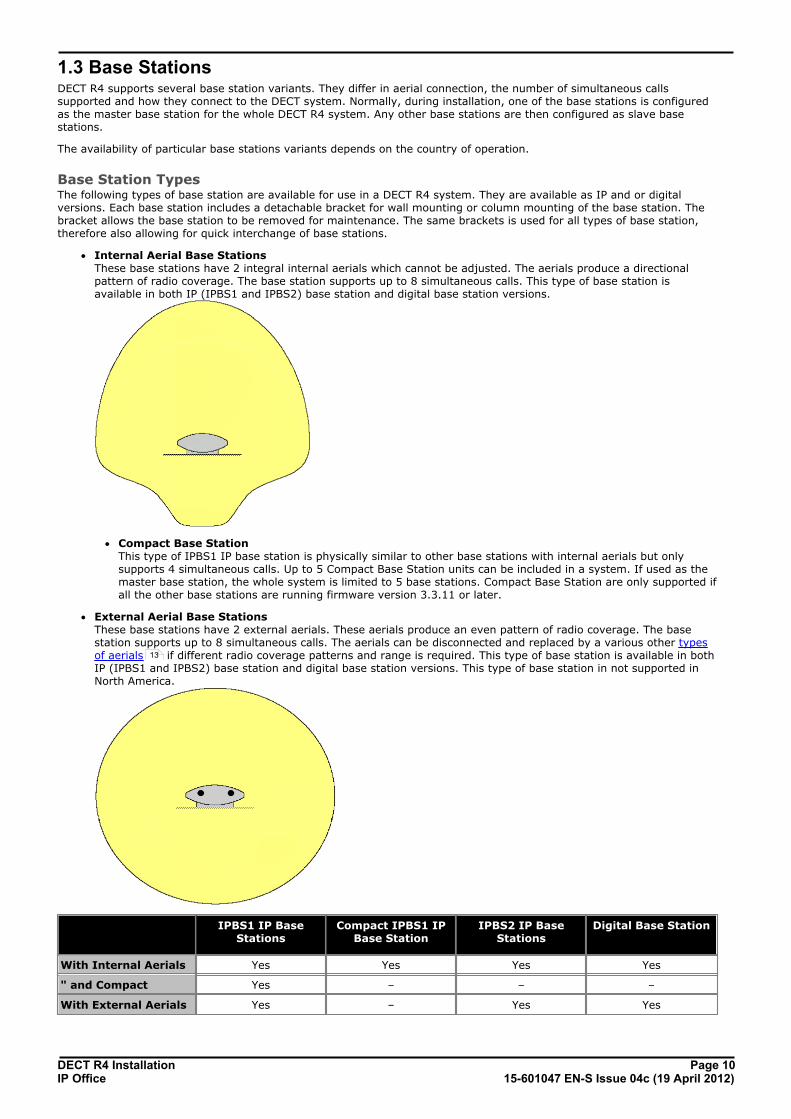
1.3 Base StationsDECT R4 supports several base station variants. They differ in aerial connection, the number of simultaneous callssupported and how they connect to the DECT system. Normally, during installation, one of the base stations is configuredas the master base station for the whole DECT R4 system. Any other base stations are then configured as slave basestations.
The availability of particular base stations variants depends on the country of operation.
Base Station TypesThe following types of base station are available for use in a DECT R4 system. They are available as IP and or digitalversions. Each base station includes a detachable bracket for wall mounting or column mounting of the base station. Thebracket allows the base station to be removed for maintenance. The same brackets is used for all types of base station,therefore also allowing for quick interchange of base stations.
· Internal Aerial Base Stations These base stations have 2 integral internal aerials which cannot be adjusted. The aerials produce a directionalpattern of radio coverage. The base station supports up to 8 simultaneous calls. This type of base station isavailable in both IP (IPBS1 and IPBS2) base station and digital base station versions.
· Compact Base Station This type of IPBS1 IP base station is physically similar to other base stations with internal aerials but onlysupports 4 simultaneous calls. Up to 5 Compact Base Station units can be included in a system. If used as themaster base station, the whole system is limited to 5 base stations. Compact Base Station are only supported ifall the other base stations are running firmware version 3.3.11 or later.
· External Aerial Base Stations These base stations have 2 external aerials. These aerials produce an even pattern of radio coverage. The basestation supports up to 8 simultaneous calls. The aerials can be disconnected and replaced by a various other typesof aerials if different radio coverage patterns and range is required. This type of base station is available in bothIP (IPBS1 and IPBS2) base station and digital base station versions. This type of base station in not supported inNorth America.
IPBS1 IP BaseStations
Compact IPBS1 IPBase Station
IPBS2 IP BaseStations
Digital Base Station
With Internal Aerials Yes Yes Yes Yes
" and Compact Yes – – –
With External Aerials Yes – Yes Yes
13

DECT R4 Installation Page 1115-601047 EN-S Issue 04c (19 April 2012)IP Office
DECT R4: Base Stations
IP Base StationsIP base stations are supplied with a mounting bracket and a 1.2 metre (4 foot) LAN cable. The base station can bepowered using IEEE 802.3af power over ethernet (PoE 7W Class 2). Alternatively the base station also requires a mainpower supply outlet socket within 8 metres (26 feet) cable distance and power supply unit.
The original IPBS1 versions of these base stations have been replaced by IPBS2 versions. The two types are functionallythe same and can be mixed in the same installation.
Digital Base StationsUsing an IP DECT Gateway , digital base stations can be connected to the DECT system. These base stations arephysically similar to the IPBS1 base stations, using the same casings and mounting brackets, but connect to the IP DECTGateway using traditional 4-wire telephone cabling.
Digital base stations can be powered either direct from the IP DECT Gateway or using separate power adapters for eachbase station. The number of base stations that the IP DECT Gateway can power depends on the cable distance to eachbase station and the type of cable used. The maximum cable length between the IP DECT Gateway and each digital basestation should not exceed 1500 meters.
Digital base stations are available in variants with internal and external aerials. There is no digital variant of the CompactBase Station base station.
· Digital Base Station with internal antennas for European Union, Switzerland, Iceland, Liechtenstein, Norway andRussia.
· Digital Base Station with external antennas for European Union, Switzerland, Iceland, Norway and Russia.
· Digital Base Station with internal antennas for US and Canada.
14

DECT R4 Installation Page 1215-601047 EN-S Issue 04c (19 April 2012)IP Office
Base Station Details
Feature Details
DECT Frequencies Brazil 1910-1920 MHz frequencies.
Latin America 1910-1930 MHz frequencies.
North America 1920-1930 MHz frequencies.
Rest of World 1880-1900 MHz frequencies.
Physical Dimensions (Height × Width × Depth)
165 × 200 × 56 mm (including mounting bracket).
Add 95mm height for external aerials.
Weight 450g
Material ABS moulded plastic
Colour Beige
External connectors 2 × RJ45, 1 x RJ12
Power (IP Base Stations)
Input Power over Ethernet IEEE 802.3af or local power supply
Operating voltage 21 to 56 V dc.
Power consumption Typical 4W, maximum 5W.
Power over Ethernet PoE Class 2 (7W).
Network (IP Base Stations)
Ethernet: 10/100baseT
Voice over IP H.323 XMobile incl. QSig/DSS1.
Voice Encoding G.711 A-law / Mu-law (64kbps)
G.723.1 (5.3 kbps)
G.729A and AB (16 kbps)
Radio RF output power EU Between 23 dBm and 28 dBm (with internal antenna)
Between 20 dBm and 25 dBm (with external antenna)
RF output power US Between 17 dBm and 21,6 dBm (with internal antenna)
Environmental Operating temperature -10°C to +55°C
Storage temperature -40°C to +70°C
Relative operating humidity 15 to 90%, non condensing
Relative storage humidity 5 to 95%, non condensing
Immunity to electromagnetic fields 3V/m (EN61000-4-3)
Immunity to ESD 4 kV contact discharge and 8 kV air discharge(EN61000-4-2)

DECT R4 Installation Page 1315-601047 EN-S Issue 04c (19 April 2012)IP Office
DECT R4: Base Stations
1.4 AerialsThe following different aerials can be used to replace the supplied aerials on a base stations with external aerials. Theseaerials have aerial leads to allow for optimal positioning. Note that these optional aerials are not supported in NorthAmerica.
· Omni-Directional Single Aerial A pair of these aerials can be used to approximately double the base station radio coverage, ie. up to 600 metres(2000 feet) omni-directional coverage.
· Directional Dual Aerial This aerial gives directional coverage up to 750 metres (2500 feet). Only one aerial unit is required for connectionto the base station.
· Directional Single Antenna A pair of these aerials can be used to give directional coverage up to 1000 metres (3300 feet). They must bemounted facing the same direction and approximately 1 metre (3 feet) apart. To achieve maximum coverage, theaerial should be mounted between 4 to 8 metres (13 to 26 feet) above area being covered.
DECT R4 Installation Page 1415-601047 EN-S Issue 04c (19 April 2012)IP Office
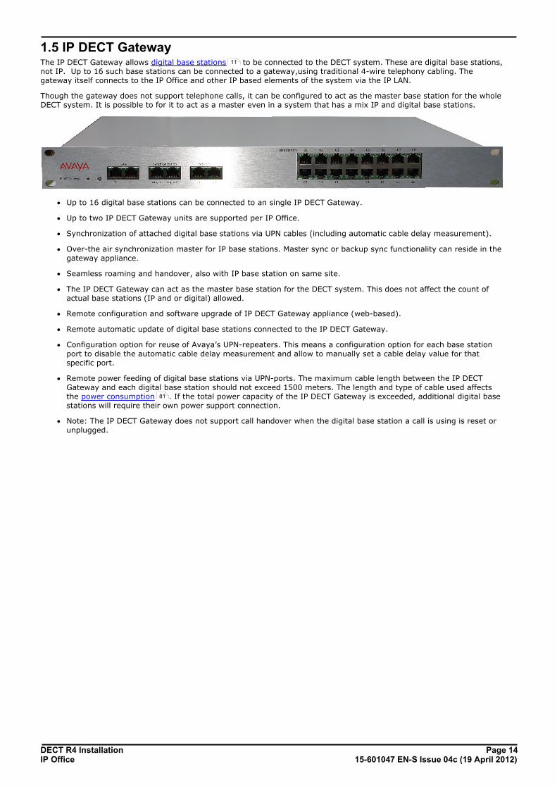
1.5 IP DECT GatewayThe IP DECT Gateway allows digital base stations to be connected to the DECT system. These are digital base stations,not IP. Up to 16 such base stations can be connected to a gateway,using traditional 4-wire telephony cabling. Thegateway itself connects to the IP Office and other IP based elements of the system via the IP LAN.
Though the gateway does not support telephone calls, it can be configured to act as the master base station for the wholeDECT system. It is possible to for it to act as a master even in a system that has a mix IP and digital base stations.
· Up to 16 digital base stations can be connected to an single IP DECT Gateway.
· Up to two IP DECT Gateway units are supported per IP Office.
· Synchronization of attached digital base stations via UPN cables (including automatic cable delay measurement).
· Over-the air synchronization master for IP base stations. Master sync or backup sync functionality can reside in thegateway appliance.
· Seamless roaming and handover, also with IP base station on same site.
· The IP DECT Gateway can act as the master base station for the DECT system. This does not affect the count ofactual base stations (IP and or digital) allowed.
· Remote configuration and software upgrade of IP DECT Gateway appliance (web-based).
· Remote automatic update of digital base stations connected to the IP DECT Gateway.
· Configuration option for reuse of Avaya’s UPN-repeaters. This means a configuration option for each base stationport to disable the automatic cable delay measurement and allow to manually set a cable delay value for thatspecific port.
· Remote power feeding of digital base stations via UPN-ports. The maximum cable length between the IP DECTGateway and each digital base station should not exceed 1500 meters. The length and type of cable used affectsthe power consumption . If the total power capacity of the IP DECT Gateway is exceeded, additional digital basestations will require their own power support connection.
· Note: The IP DECT Gateway does not support call handover when the digital base station a call is using is reset orunplugged.
11
81

DECT R4 Installation Page 1515-601047 EN-S Issue 04c (19 April 2012)IP Office
DECT R4: IP DECT Gateway
1.6 PhonesThe following Avaya 3700 Series phones are supported by DECT R4.
1.6.1 3720
Avaya 3720 Description
Features · High quality voice DECT phone, GAP/CAPcompliant.
· Easy access to PBX services.
· Voicemail including message icon.
· Manual and automatic keypad lock.
· Local directory: 250 entries.
· Central directory from the IP Office.
· Call list with the 25 last calls.
· Vibrator.
· Loudspeaker/hands free.
· Central Management and software download.
· Headset socket (2.5mm).
· 5 languages* English, German, Spanish, French. One additionallanguage can be uploaded.
· Monochrome display (112 x 115 pixels).
· GAP compatible.
Physical Dimension 133 x 53 x 24mm
Weight 115g
Battery Type 600 mAh, Lithium 3.7V. Charge time 4 hours.
Speech Time > 16 hours.
Standby Time > 160 hours.
· *For systems installed using IP Office provisioning, the language used is set by the IP Office system or userlanguage setting.
· An additional language file can be uploaded to a phone.

DECT R4 Installation Page 1615-601047 EN-S Issue 04c (19 April 2012)IP Office
1.6.2 3725
Avaya 3725 Description
Features · As per 3725 plus:
· Site Survey tool.
· Cleanable, IP 44.
· Option: Bluetooth.
· 19 Languages Czech, Danish, Dutch, English, Finnish, French,German, Greek, Hungarian, Italian, Norwegian,Polish, Portuguese (Brazilian), Portuguese,Russian, Slovakian, Spanish, Swedish andTurkish.
· Colour display (128 x 160 pixels).
· SMS Message length up to 160 characters. 30received/sent messages. Requires AIWS .
· GAP compatible.
Physical Dimension 134 x 53 x 26mm
Weight 130g
Battery Type 930 mAh, Li-Pol 3.7V. Charge time 4 hours.
Speech Time > 20 hours (13h with Bluetooth option)
Standby Time > 120 hours.
· *For systems installed using IP Office provisioning, the language used is set by the IP Office system or userlanguage setting.
· An additional language file can be uploaded to a phone.
122

DECT R4 Installation Page 1715-601047 EN-S Issue 04c (19 April 2012)IP Office
DECT R4: Phones
1.6.3 3740
Avaya 3740 Description
Features · High quality voice DECT phone, GAP/CAPcompliant
· Easy access to PBX services
· Voicemail including message icon.
· Manual and automatic keypad lock
· Local directory: 250 entries.
· Central directory from the IP Office.
· Call list with the 25 last calls
· Vibrator
· Loudspeaker/hands free
· Central Management and software download
· Headset socket (IP65 plug).
· 19 Languages Czech, Danish, Dutch, English, Finnish,French, German, Greek, Hungarian, Italian,Norwegian, Polish, Portuguese (Brazilian),Portuguese, Russian, Slovakian, Spanish,Swedish and Turkish.
· Ruggedized.
· IP65 Classified.
· Wide temperature range: -10C to 55C.
· Monochrome display (128 x 160 pixels).
· SMS Message length up to 160 characters. 30received/sent messages. Requires AIWS .
· GAP compatible.
Physical Dimension 143 x 59 x 29mm
Weight 180g
Battery Type 920 mAh, Li-lon 3.7V. Charge time 4 hours.
Speech Time > 18 hours.
Standby Time > 150 hours.
· *For systems installed using IP Office provisioning, the language used is set by the IP Office system or userlanguage setting.
· An additional language file can be uploaded to a phone.
122

DECT R4 Installation Page 1815-601047 EN-S Issue 04c (19 April 2012)IP Office
1.6.4 3749
Avaya 3749 Description
Features · High quality voice DECT phone, GAP/CAPcompliant
· Easy access to PBX services
· Voicemail including message icon.
· Manual and automatic keypad lock
· Local directory: 250 entries.
· Central directory from the IP Office.
· Call list with the 25 last calls
· Vibrator
· Option: Bluetooth.
· Loudspeaker/hands free
· Central Management and softwaredownload
· Headset socket (IP65 plug).
· 19 Languages Czech, Danish, Dutch, English, Finnish,French, German, Greek, Hungarian,Italian, Norwegian, Polish, Portuguese(Brazilian), Portuguese, Russian,Slovakian, Spanish, Swedish and Turkish.
· Ruggedized.
· IP65 Classified.
· Intrinsically Safe. Conforms toATEX/IECEx
· Wide temperature range: -10C to 55C.
· Colour display (128 x 160 pixels).
· SMS Message length up to 160 characters. 30received/sent messages. Requires AIWS
.
· GAP compatible.
Physical
Dimension 143 x 59 x 29mm
Weight 180g
Battery Type 920 mAh, Li-lon 3.7V. Charge time 4 hours.
Speech Time > 10 hours.
StandbyTime
> 80 hours.
· Due to the power restrictions for intrinsically safe handset operation, the display brightness is lower, theloudspeaker and ringer volumes are lower and the audible ringer and vibrating alert cannot be activatedsimultaneously.
· *For systems installed using IP Office provisioning, the language used is set by the IP Office system or userlanguage setting.
· An additional language file can be uploaded to a phone.
122

DECT R4 Installation Page 1915-601047 EN-S Issue 04c (19 April 2012)IP Office
DECT R4: Phones
1.7 ChargersA number of different types of charger exist for 3700 Series phones. Note that chargers for 3720/3725 phones are notuseable with 3740/3749 phones and vice versa.
· Basic Chargers These are simple single-phone charger for charging only. The basic charger for 3720/3725 phones is not usablewith 3740/3749 phones and vice versa.
· Advanced Chargers These are single-phone chargers with USB and LAN sockets. These allow the phone docked with the charger to beaccessed using the Device Manager application (browser access via the AIWS unit and charger LAN port or WinPDMPC application access via the USB port). The advanced charger for 3720/3725 phones is not usable with 3740/3749phones and vice versa.
· Rack Chargers These are 6 phone advanced chargers. Older designs of the rack charger for 3720/3725 phones are not usable with3740/3749 phones and vice versa. However, the latest design of rack charger is usable with all 3720, 3725, 3740and 3749 phones.
· Battery Chargers These chargers allows the charging of up to 6 batteries separate from the phones. The battery charger for3720/3725 phones is not usable with 3740/3749 phones and vice versa. There is no battery charger for 3749phones.

DECT R4 Installation Page 2015-601047 EN-S Issue 04c (19 April 2012)IP Office
1.8 AIWSThe AIWS (Avaya In-Built Wireless Server) unit allows SMS messaging between handsets. It also allows wireless softwareupgrades and configuration of the handsets. Without an AIWS, handsets can only be upgraded and configured when in anadvanced charger.
For IP Office Release 5 this unit also provides directory integration between the IP Office and the DECT R4 system.
For IP Office Release 6 and higher, directory integration is done by the master base station without requiring an AIWS.However an AIWS is still required for both functions if SMS is needed.
The unit is managed via web browser and requires a fixed IP address.

DECT R4 Installation Page 2115-601047 EN-S Issue 04c (19 April 2012)IP Office
DECT R4: AIWS
1.8.1 AIWS2For IP Office 8.0, the AIWS2 is supported. The AIWS2 is an application server for the DECT R4 system. It can runapplications such DECT phone users such as SMS messaging, centralized phonebook and corporate directory access. Formaintainers it supports centralized device management including firmware and configuration upgrades over the air.
· Wall mounting brackets are included with the unit. Various other mounting kits are available.
· Built-in power supply. The AIWS is supplied with a number of power leads suitable for most locales.
· For installation and maintenance, this server is managed by a PC using Windows Internet Explorer (7.0 or above)and Sun’s Java Runtime Environment.
Several variants of the server are available. There is no upgrade available between variants.
Feature\AIWS2 Variant Basic Basic+ Standard OAP
NTP Server Yes Yes Yes Yes
Central Phonebook Yes Yes Yes Yes
Corporate Directory Access(TFTP from IP Office)
Yes Yes Yes –
SMS Support Yes Yes Yes Yes
Basic Web Messaging Yes Yes Yes Yes
Netpage Web Messaging – Yes[1] Yes –
Over-the-Air Handset Software Upload – Yes[1] Yes[2] –
Over-the-Air Handset Configuration Upload – Yes[1] Yes[2] –
Handset Software Upload via Advanced/Rack Charger – Yes[1] Yes[2] –
Handset Configuration Upload via Advanced/Rack Charger – Yes[1] Yes[2] –
Virtual SIM Card – Yes[1] Yes[2] –
AIWS as Protocol Converter – – – Yes
1.Up to 32 handsets.
2.Up to 120 handsets.

DECT R4 Installation Page 2215-601047 EN-S Issue 04c (19 April 2012)IP Office
1.8.2 AIWS1This design of AIWS has now been replaced by the AIWS2.
· Wall mountable.
· Dimensions: 275 x 130 x 60 mm, 550g.
· Supplied with power supply unit and power cords.
Several variants of the server are available. There is no upgrade available between variants.
Feature\AIWS2 Variant Basic Standard Enterprise OAP
Central Phonebook Yes Yes Yes
Corporate Directory Access Yes(TFTP only)
Yes(TFTP and
LDAP)
– –
SMS Support Yes Yes Yes Yes
Basic Web Messaging Yes Yes Yes Yes
Netpage Web Messaging – Yes – –
Over-the-Air Handset Software Upload – Yes[1] Yes –
Over-the-Air Handset Configuration Upload Yes Yes[1] Yes –
Handset Software Upload via Advanced/Rack Charger – Yes[1] Yes –
handset Configuration Upload via Advanced/Rack Charger – Yes[1] Yes –
Virtual SIM Card – Yes[1] Yes –
AIWS as Protocol Converter – – – Yes
1.Up to 120 handsets.
DECT R4 Installation Page 2315-601047 EN-S Issue 04c (19 April 2012)IP Office
Site Survey and Planning
Chapter 2.

DECT R4 Installation Page 2415-601047 EN-S Issue 04c (19 April 2012)IP Office
2. Site Survey and PlanningWe cannot give precise recommendations for a site survey as every site will vary. However a site survey is a prerequisiteto installation in all cases. The correct and effective placement of base stations will prevent problems and maximizecoverage. Most issues with any DECT system will arise from the number and positioning of the base stations.
The basic aim is to ensure:
· Base station coverage in all areas of expected DECT phone usage.
· Sufficient number of base stations covering each area for the number of expected simultaneous users (up to 8 perbase station) in that area.
· Sufficient overlap between areas of base station coverage to allow for call handover when DECT phone usersare moving.
· Where possible, synchronization of each base station with more than one other base station.
The diagram below indicates the basic measures for coverage between a base station and a DECT phone.
Signal Description
-40dB Strong signal typically seen when a phone is close to the base station.
-62dB Minimum signal strength at which a base station will accept a phone wanting to handover from another basestation.
-68dB Signal strength below which the phone will begin looking for a base station to which it can handover.
-75dB At this signal strength, the increased error rate will become apparent in the speech.
-90dB At this signal strength calls are likely to disconnect. This is also the limit for one base station to synchronizewith another.
Though this section focuses mainly on the measure of signal strength, the DECT signalling employs a number of methodsto overcome a poor signal. The other key factor that affects signalling is the error rate. While decreasing signal strengthand increasing error rate are usually related, there may be some scenarios where a higher than expected error rateoccurs.
26
27
DECT R4 Installation Page 2515-601047 EN-S Issue 04c (19 April 2012)IP Office
Site Survey and Planning: Factors to Consider
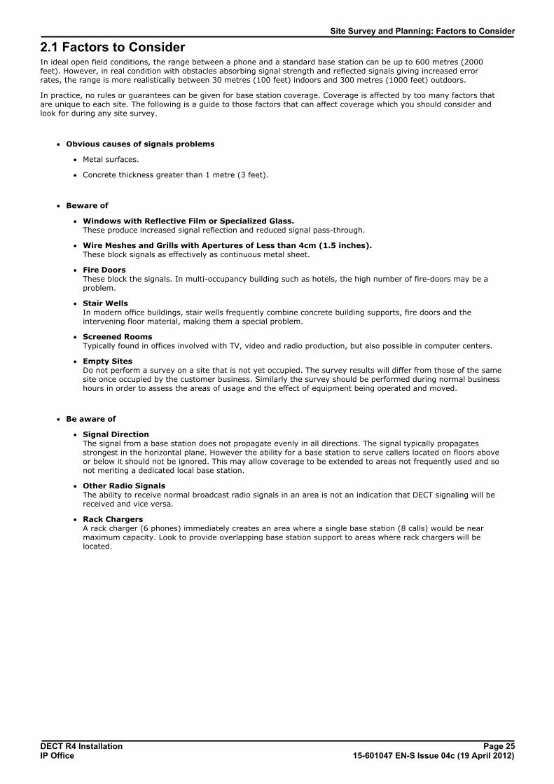
2.1 Factors to ConsiderIn ideal open field conditions, the range between a phone and a standard base station can be up to 600 metres (2000feet). However, in real condition with obstacles absorbing signal strength and reflected signals giving increased errorrates, the range is more realistically between 30 metres (100 feet) indoors and 300 metres (1000 feet) outdoors.
In practice, no rules or guarantees can be given for base station coverage. Coverage is affected by too many factors thatare unique to each site. The following is a guide to those factors that can affect coverage which you should consider andlook for during any site survey.
· Obvious causes of signals problems
· Metal surfaces.
· Concrete thickness greater than 1 metre (3 feet).
· Beware of
· Windows with Reflective Film or Specialized Glass. These produce increased signal reflection and reduced signal pass-through.
· Wire Meshes and Grills with Apertures of Less than 4cm (1.5 inches). These block signals as effectively as continuous metal sheet.
· Fire Doors These block the signals. In multi-occupancy building such as hotels, the high number of fire-doors may be aproblem.
· Stair Wells In modern office buildings, stair wells frequently combine concrete building supports, fire doors and theintervening floor material, making them a special problem.
· Screened Rooms Typically found in offices involved with TV, video and radio production, but also possible in computer centers.
· Empty Sites Do not perform a survey on a site that is not yet occupied. The survey results will differ from those of the samesite once occupied by the customer business. Similarly the survey should be performed during normal businesshours in order to assess the areas of usage and the effect of equipment being operated and moved.
· Be aware of
· Signal Direction The signal from a base station does not propagate evenly in all directions. The signal typically propagatesstrongest in the horizontal plane. However the ability for a base station to serve callers located on floors aboveor below it should not be ignored. This may allow coverage to be extended to areas not frequently used and sonot meriting a dedicated local base station.
· Other Radio Signals The ability to receive normal broadcast radio signals in an area is not an indication that DECT signaling will bereceived and vice versa.
· Rack Chargers A rack charger (6 phones) immediately creates an area where a single base station (8 calls) would be nearmaximum capacity. Look to provide overlapping base station support to areas where rack chargers will belocated.

DECT R4 Installation Page 2615-601047 EN-S Issue 04c (19 April 2012)IP Office
2.2 HandoverOnce a phone is connected on a call through a particular base station, it will normally maintain connection with that basestation even if the phone moves into an area with a stronger signal from another base station. However, when the signalto the phone drops below -68dB, the phone will begin looking for another base station with a better signal to which it canhandover (this is often referred to as "roaming"). If the other base station signal is -62dB or higher, the phone willhandover to that base station if it has free capacity.
DECT R4 Installation Page 2715-601047 EN-S Issue 04c (19 April 2012)IP Office
Site Survey and Planning: Handover
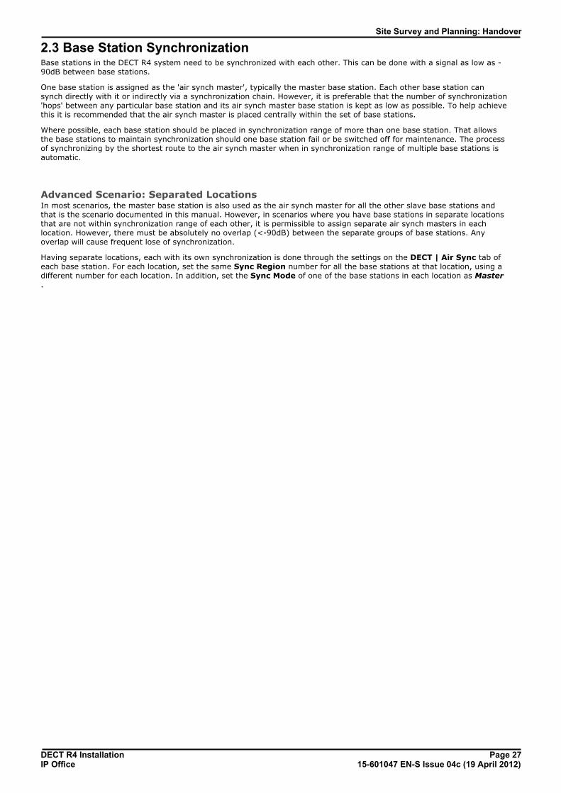
2.3 Base Station SynchronizationBase stations in the DECT R4 system need to be synchronized with each other. This can be done with a signal as low as -90dB between base stations.
One base station is assigned as the 'air synch master', typically the master base station. Each other base station cansynch directly with it or indirectly via a synchronization chain. However, it is preferable that the number of synchronization'hops' between any particular base station and its air synch master base station is kept as low as possible. To help achievethis it is recommended that the air synch master is placed centrally within the set of base stations.
Where possible, each base station should be placed in synchronization range of more than one base station. That allowsthe base stations to maintain synchronization should one base station fail or be switched off for maintenance. The processof synchronizing by the shortest route to the air synch master when in synchronization range of multiple base stations isautomatic.
Advanced Scenario: Separated LocationsIn most scenarios, the master base station is also used as the air synch master for all the other slave base stations andthat is the scenario documented in this manual. However, in scenarios where you have base stations in separate locationsthat are not within synchronization range of each other, it is permissible to assign separate air synch masters in eachlocation. However, there must be absolutely no overlap (<-90dB) between the separate groups of base stations. Anyoverlap will cause frequent lose of synchronization.
Having separate locations, each with its own synchronization is done through the settings on the DECT | Air Sync tab ofeach base station. For each location, set the same Sync Region number for all the base stations at that location, using adifferent number for each location. In addition, set the Sync Mode of one of the base stations in each location as Master.

DECT R4 Installation Page 2815-601047 EN-S Issue 04c (19 April 2012)IP Office
2.4 Performing a Survey· While performing a survey you will require the following information:
· Building Layout Accurate building plans are an essential aid to both the site survey and also for later fault analysis. Ensure thatyou have an accurate plan of the customer premises, including the locations of mains power outlets andnetwork connection points.
· The area of coverage required? Which areas within the plans the customer expects to be covered. Do they expect coverage outside the buildingand or in buildings separate from the main building.
· The number of simultaneous users within different areas? Each base station can support up to 8 simultaneous calls (4 for a Compact Base Station).
· Perform the survey during normal business hours. The movement of large items of machinery, such as lifts andshutter doors, will then be observable during the survey.
· Ensure that you have read this documentation and understand the requirement of both phone handover andbase station synchronization .
· As the survey takes place, note whether additional network connection points will be required and or mains poweroutlets. Consider the use of Power over Ethernet, if possible in order to simplify base station installation.
26
27

DECT R4 Installation Page 2915-601047 EN-S Issue 04c (19 April 2012)IP Office
Site Survey and Planning: Performing a Survey
Site Survey ModeThe following method is used to put a subscribed phone into site survey mode.
1.Go to the Call Time menu (Menu | Calls | Call Time).
2.Activate the Admin menu by pressing * * .
3.In Admin menu, select DECT Info.
4.Select Link. The phone will display information about the base station.
· C7 S10 This is the DECT signal carrier and slot.
· ss This is the signal strength . This is the main value that should be recorded and accessed as you perform thesurvey.
Signal Description
-40dB Strong signal typically seen when a phone is close to the base station.
-62dB Minimum signal strength at which a base station will accept a phone wanting to handover from another basestation.
-68dB Signal strength below which the phone will begin looking for a base station to which it can handover.
-75dB At this signal strength, the increased error rate will become apparent in the speech.
-90dB At this signal strength calls are likely to disconnect. This is also the limit for one base station to synchronizewith another.
· Error rate / Q2 Error rate These are the error (corrupted) frames per second on the signals from and to the base station.
· PARI The PARI of the DECT system.
· Bear: The current power output of the phone.
· Pwr = on hook
· LU = off hook, Low power
· US = off hook, Normal power
· EU = off hook, High power
24


DECT R4 Installation Page 3115-601047 EN-S Issue 04c (19 April 2012)IP Office
Provisioned Installation
Chapter 3.
DECT R4 Installation Page 3215-601047 EN-S Issue 04c (19 April 2012)IP Office
3. Provisioned InstallationA provisioned install is the recommended method for both installation simplicity and handset feature support. It should beused for all installations using just Avaya 3700 Series phones.
· When to Use IP Office Provisioning IP Office provisioning both simplifies installation and maintenance and provides 3720, 3725, 3740 and 3749phones with additional IP Office specific features. Therefore it is the recommended installation method for newinstallations whenever possible.
· Provisioning installation in pre-configured or auto-create modes should be used for all installations withjust 3720, 3725, 3740 and 3749 phones.
· Provisioning installation in pre-configured mode should be used for all installations with a mix of 3720,3725, 3740, 3749 phones and other DECT phones.
· Provisioning installation should not be used for installations with no 3720, 3725, 3740 or 3749 phones.
1.Unpack the latest IP DECT software .
2.Configure the IP Office for provisioned operation .
3.Configure the Master Base Station .
4.Configure the Slave Base Stations .
5.Base Station Mounting .
6.Phone Subscription .
The installation process used here is only an example. Other methods and order can be used once you become familiarwith the installation process. For example, installing all the slave base stations before installing the master base station.
IP Office Installation Requirements· It is assumed that you are familiar with installation and configuration of IP Office systems.
Information· Service user name and password for IP Office configuration access.
· Service user name and password for IP Office security settings access.
· IP Office IP address.
· Avaya IP Endpoint licenses
Parts Required· IP Office Release 7.0 software DVD or image of the IP Office Release 7.0 admin software.
Tools Required· Programming PC with IP Office Manager application installed. You must have rights on this PC to change its IP
address settings unless it is a DHCP client.
· Software for zip file extraction.
34
35
44
54
61
63

DECT R4 Installation Page 3315-601047 EN-S Issue 04c (19 April 2012)IP Office
Provisioned Installation:
IP Base Station Installation Requirements
Parts Required· Base station
Includes:
· Base station.
· Two 3.5mm screws and two 6mm wall plugs suitable for wall mounting onto a solid wall (brick or similar).
· 1.2 metre (4 foot) LAN cable. If this is replaced with a longer cable the replacement should be a CAT5 EthernetLAN cable.
· If using Power over Ethernet:
· The base station supports Power over Ethernet, IEEE 802.3af, class 2.
· If not using Power over Ethernet:
· Base station power supply unit. Required if not using Power over Ethernet to power the base station. Note that the base station power supplyunits include an 8 metre (26 feet) cable from the PSU to the base station. Check that you have the correct typeof power supply unit for the locale.
· BSX-0013: Europe (except United Kingdom).
· BSX-0014: United Kingdom.
· BSX-0015: USA/Canada.
· BSX-0016: Australia.
· Mains power outlet socket.
· LAN Socket.
Information· DECT R4 SARI.
· Base Station IP Addresses.
· Detailed plans from the site survey indicating the intended base station locations, LAN sockets and if necessarypower supply outlets.
Tools· Programming PC with DECT R4 software.
· Web browser.
· Drill and drill bits suitable for the selected wall mounting position of the AIWS.
· Screwdrivers for use with the screws selected for AIWS wall mounting.
Phone Subscription Requirements
Information· Service user name and password for IP Office configuration.
· User names and extension numbers for the DECT phones.
· Phone IPEI numbers if using an pre-configured installation mode.
Tools· IP Office Manager.
· Device Manager The software installed on each handset may need to be upgraded to match that supplied with the DECT R4 software
. This is done using the Windows Device Manager software to upgrade phones via an advanced charger orusing AIWS Device Manager to upgrade phones over the air.
· Web browser (Internet Explorer or Firefox are supported).
34
95
DECT R4 Installation Page 3415-601047 EN-S Issue 04c (19 April 2012)IP Office
3.1 DECT SoftwareBefore beginning installation, in addition to having IP Office Manager installed, you need to unpack the DECT R4 softwareonto your programming PC.
DECT R4 is supported on a range of Avaya systems. However, for IP Office operation, only firmware specificallydocumented as having been tested and supported with IP Office should be used. Details of supported firmware will beincluded in IP Office Technical Bulletins and Technical Tips.
1.On the programming PC, create a folder with a name indicating its purpose, for example c:\IP_DECT_R4.
2.Within the IP Office Administrator Application software (ie. the software from which IP Office Manager is installed),locate the folder IPDECT.
3.The folder contains a file DECT R4.zip. This is the file containing software for DECT R4. The file IPDECT.zipcontains software for the previously supported IP DECT product and not for DECT R4.
4.Copy the DECT R4.zip file to the folder created on the programming PC.
5.Using WinZip or a similar tool, extract the contents of the zip file into the folder, maintaining the directory structureof the zip files.
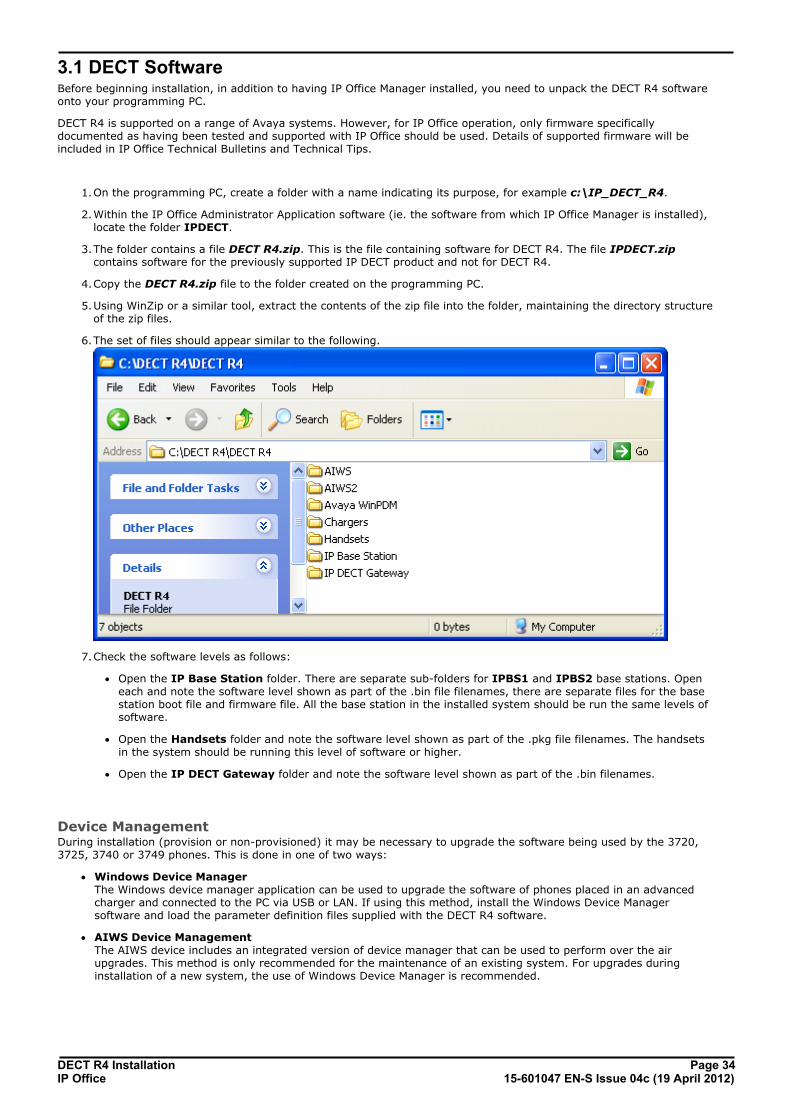
6.The set of files should appear similar to the following.
7.Check the software levels as follows:
· Open the IP Base Station folder. There are separate sub-folders for IPBS1 and IPBS2 base stations. Openeach and note the software level shown as part of the .bin file filenames, there are separate files for the basestation boot file and firmware file. All the base station in the installed system should be run the same levels ofsoftware.
· Open the Handsets folder and note the software level shown as part of the .pkg file filenames. The handsetsin the system should be running this level of software or higher.
· Open the IP DECT Gateway folder and note the software level shown as part of the .bin filenames.
Device ManagementDuring installation (provision or non-provisioned) it may be necessary to upgrade the software being used by the 3720,3725, 3740 or 3749 phones. This is done in one of two ways:
· Windows Device Manager The Windows device manager application can be used to upgrade the software of phones placed in an advancedcharger and connected to the PC via USB or LAN. If using this method, install the Windows Device Managersoftware and load the parameter definition files supplied with the DECT R4 software.
· AIWS Device Management The AIWS device includes an integrated version of device manager that can be used to perform over the airupgrades. This method is only recommended for the maintenance of an existing system. For upgrades duringinstallation of a new system, the use of Windows Device Manager is recommended.
DECT R4 Installation Page 3515-601047 EN-S Issue 04c (19 April 2012)IP Office
Provisioned Installation: DECT Software
3.2 IP Office ConfigurationThe IP Office configuration for a provision installation consists of the following steps:
1.Check and configure IP Office security settings .
2.Setup the IP DECT Line
3.Add IP Endpoint licenses .
4.Manually create extensions (optional) .
Requirements· It is assumed that you are familiar with installation and configuration of IP Office systems.
Information· Service user name and password for IP Office configuration access.
· Service user name and password for IP Office security settings access.
· IP Office IP address.
· Avaya IP Endpoint licenses
Parts Required· IP Office Release 7.0 software DVD or image of the IP Office Release 7.0 admin software.
Tools Required· Programming PC with IP Office Manager application installed. You must have rights on this PC to change its IP
address settings unless it is a DHCP client.
· Software for zip file extraction.
36
38
41
43

DECT R4 Installation Page 3615-601047 EN-S Issue 04c (19 April 2012)IP Office
3.2.1 Security SettingsThe provisioning connection between the IP Office control unit and the master base station uses the HTTP/HTTPS serviceconfigured in the IP Office system's security settings.
· For new IP Office systems installed with IP Office Release 7.0, the appropriate security settings are configured bydefault. However it is still important to check the settings and to be aware of the controls that are used.
· For existing IP Office systems upgraded to IP Office Release 7.0, the default settings may not necessarily becreated as required. Therefore you must check the security settings and adjust them if required.
1.Start IP Office Manager and receive the configuration from the system.
2.Receiving the configuration will switch IP Office Manager from simplified view mode to advanced view mode(security settings are not accessible in simplified view mode).
3.Select File | Advanced | Security Settings....
4.From the discovery menu select the IP Office and click OK.
5.Enter the systems user name and password for the security service user login. They will be different from the nameand password used for IP Office configuration access.
6.Select Services. The list of services should include one called HTTP. Select this service.
a. If the service is not present then the system has not been upgraded to run IP Office Release 7.0 or highersoftware.
b.The HTTP service affects all HTTP connections provided by the IP Office system. Changing its setting will affectapplications other than just the DECT R4. The only option that change be changed is the Service SecurityLevel. The default is Secure + Unsecure, meaning both http and https can be used between the base stationand IP Office.
· Unsecure Only HTTP port 80 available and used for phone files, embedded file manager, system file upgrade, one-X Portaldirectory services, DECT R4 provisioning, IP Office Video Softphone provisioning.
· Secure + Unsecure This mode (the default) allows both unsecure HTTP (see above) and secure HTTPS (see below)connections.
· Secure, Low HTTPS port 443 available and used for DECT R4 provisioning, IP Office Video Softphone provisioning. Thisoption allows secure access to that service using TLS, and demands weak (for example DES_40 + MD5) encryption and authentication or higher. The service's unsecured TCP port is disabled.
· Secure, Medium This option allows secure access to that service using TLS, and demands moderate (for example DES_56 +SHA-1) encryption and authentication or higher. The service's unsecured TCP port is disabled.
· Secure, High This option allows secure access to that service using TLS and demands strong (for example 3DES + SHA-1) encryption and authentication, or higher. In addition, a certificate is required from the client (usuallyManager). For further details of security certificates see the IP Office Security Mode section in the IP OfficeManager manual.

DECT R4 Installation Page 3715-601047 EN-S Issue 04c (19 April 2012)IP Office
Provisioned Installation: IP Office Configuration
7.Select Rights Groups. The list of groups should contain one called IPDECT Group. Select that group. If the
group is not present in the list, click on the new entry icon and create the group.
a.Select the HTTP tab. Check that the option DECT R4 Provisioning is selected.
b.Check that on the other tabs no other options are selected.
8.Select Service Users. The list of users should include one called IPDectService. Select that user.
a. In the Rights Group Membership list check that the user is set as a member of the IPDECT Group.
b.Leave the Account Status as Enabled and the Account Expiry as <None>.
9.Click on the icon to save any changes you have made to the security settings.

DECT R4 Installation Page 3815-601047 EN-S Issue 04c (19 April 2012)IP Office
3.2.2 IP DECT Line SetupAt this stage we will create an IP DECT line for traffic between the IP Office and the DECT R4 system. The line isconfigured with the IP address of the master base station. The IP Office configuration only requires and allows a single IPDECT line.
· Reboot Required Add or removing a line from the IP Office configuration requires the IP Office system to reboot. This will end all callsand services in progress.
1.Using IP Office Manager, receive the configuration from the IP Office system.
2.Click on Line. The list of existing lines is shown.
3.Click on the icon and select IP DECT Line. The settings for an IP DECT line are displayed. If the option is greyedout then the configuration already contains an IP DECT line.
4.On the Line tab there are no adjustable settings. Once the system is installed and operational, this tab will list theDECT extensions.
5.Select the VoIP tab. This table is used to set details of the master base station.
a.Set the Gateway IP Address to match the IP address that will be assigned to the master base station. TheMAC Address field is not used.
b.Leave the other fields at their default settings.
DECT R4 Installation Page 3915-601047 EN-S Issue 04c (19 April 2012)IP Office
Provisioned Installation: IP Office Configuration
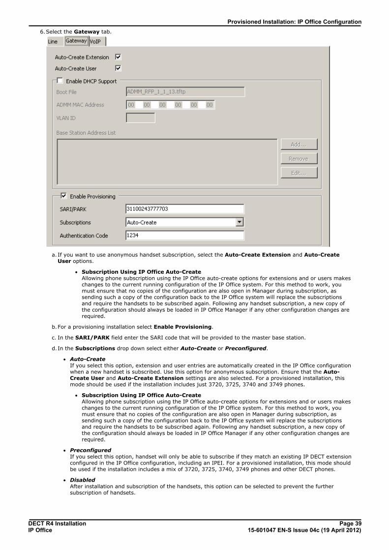
6.Select the Gateway tab.
a. If you want to use anonymous handset subscription, select the Auto-Create Extension and Auto-CreateUser options.
· Subscription Using IP Office Auto-Create Allowing phone subscription using the IP Office auto-create options for extensions and or users makeschanges to the current running configuration of the IP Office system. For this method to work, youmust ensure that no copies of the configuration are also open in Manager during subscription, assending such a copy of the configuration back to the IP Office system will replace the subscriptionsand require the handsets to be subscribed again. Following any handset subscription, a new copy ofthe configuration should always be loaded in IP Office Manager if any other configuration changes arerequired.
b.For a provisioning installation select Enable Provisioning.
c. In the SARI/PARK field enter the SARI code that will be provided to the master base station.
d. In the Subscriptions drop down select either Auto-Create or Preconfigured.
· Auto-Create If you select this option, extension and user entries are automatically created in the IP Office configurationwhen a new handset is subscribed. Use this option for anonymous subscription. Ensure that the Auto-Create User and Auto-Create Extension settings are also selected. For a provisioned installation, thismode should be used if the installation includes just 3720, 3725, 3740 and 3749 phones.
· Subscription Using IP Office Auto-Create Allowing phone subscription using the IP Office auto-create options for extensions and or users makeschanges to the current running configuration of the IP Office system. For this method to work, youmust ensure that no copies of the configuration are also open in Manager during subscription, assending such a copy of the configuration back to the IP Office system will replace the subscriptionsand require the handsets to be subscribed again. Following any handset subscription, a new copy ofthe configuration should always be loaded in IP Office Manager if any other configuration changes arerequired.
· Preconfigured If you select this option, handset will only be able to subscribe if they match an existing IP DECT extensionconfigured in the IP Office configuration, including an IPEI. For a provisioned installation, this mode shouldbe used if the installation includes a mix of 3720, 3725, 3740, 3749 phones and other DECT phones.
· Disabled After installation and subscription of the handsets, this option can be selected to prevent the furthersubscription of handsets.

DECT R4 Installation Page 4015-601047 EN-S Issue 04c (19 April 2012)IP Office
· In the Authentication Code field enter the numeric code that handset should enter during thesubscription process. This needs to be 4 to 8 digits long.
7.Save the configuration back to the IP Office system.

DECT R4 Installation Page 4115-601047 EN-S Issue 04c (19 April 2012)IP Office
Provisioned Installation: IP Office Configuration
3.2.3 Adding LicensesEach IP DECT extension requires an Avaya IP Endpoint license. This applies even if the handset subscribed to the IP DECTR4 system is not an Avaya phone.
Phones without a license will still be able to subscribe and register but will be limited to making emergency calls only (callsthat match an IP Office Dial Emergency short code). The associated user will be treated as if logged off. If a licensebecomes available, it will be assigned to any unlicensed DECT handsets first and then to any other unlicensed Avaya IPphone in the order that the phones registered.
· Avaya IP Endpoint Licenses Licenses are added to the IP Office configuration and are based on a serial number unique to the system.
· Phones can be licensed up to the 384 extension limit for all phone extensions of any type.
· For each IP500 VCM 32 or IP500 VCM 64 card installed in the system also enables 12 Avaya IP endpointswithout requiring licenses.
· For each IP400 VCM card installed in the system, each VCM channel supported by the card allows supportfor 3 Avaya IP phones.
· The VCM channels provided by IP500 Combination cards do not enable any Avaya IP endpoints.
· Licenses are normally automatically assigned to extensions in order of registration. However, existingextensions can be configured to reserve a license . This ensures that they do not become unlicensedwhen newly added extensions manage to register first following a system reboot.
3.2.3.1 Checking the Licensing Number
IP Office licenses are issued against a unique dongle serial number. For IP500 control units, the number is unique to thesmart card fitted to the control unit. For IP500v2 control units, the number is unique to the System SD card fitted to thesystem. For any licenses entered into the system configuration to be valid, they must be licenses issued against that serialnumber.
1.Using IP Office Manager, receive the configuration from the IP Office system.
2.Select System.
3.Select the System tab.
4.The feature key serial number is shown by the Dongle Serial Number field.
3.2.3.2 Adding Licenses
1.Using IP Office Manager, receive the configuration from the IP Office system.
2.Select License.
3.The current licenses in the system configuration are displayed.
4.To add a license click on and select License.
5.Enter the license which you have been supplied and click OK.
6.The type of the license, Avaya IP endpoints, should be displayed but with its License Status set to Unknown. Ifthe License Type was not recognized, check that the key was entered correctly.
7.Save the configuration back to the IP Office system and then receive the configuration from the IP Office systemagain.
8.The License Status should now be Valid.
42

DECT R4 Installation Page 4215-601047 EN-S Issue 04c (19 April 2012)IP Office
3.2.3.3 Reserving Licenses
Licenses are normally automatically assigned to extensions in order of registration. However existing extensions canreserve a license in order to ensure they do not become unlicensed when new extensions added to the system manage toregister first following a system reboot.
1.Using IP Office Manager, receive the configuration from the IP Office system.
2.Select Extension and then select the DECT extension.
3.Select the IP DECT tab. Note, the appearance of this menu will vary depending on whether you are doing aprovisioned or non-provisioned installation.
4.The Reserve Avaya IP endpoint license setting is used to reserve an existing license for the extension. Theoption is greyed out if the configuration does not have sufficient unreserved licenses remaining.
5.Repeat the process for any other extensions for which you want to reserve the license.
6.Save the configuration back to the IP Office system.

DECT R4 Installation Page 4315-601047 EN-S Issue 04c (19 April 2012)IP Office
Provisioned Installation: IP Office Configuration
3.2.4 Manually Creating ExtensionsIf the IP DECT line's subscription setting is set to Preconfigured, you must manually add extension and user entries foreach handset to the IP Office configuration.
1.Using IP Office Manager, receive the configuration from the IP Office system.
2.Click on Extension.
3.Click on the icon and select IP DECT Extension. This option is greyed out until an IP DECT line is added to theconfiguration.
4.Select the Extn tab. Set the Base Extension number to a currently unused extension number.
5.Select the IP DECT tab. Note that the appearance of this tab varies depend on whether the IP DECT line hasEnable Provisioning selected or not, this example is for provisioning enabled.
a.Set the Message Waiting Lamp Indication Type to On. For
b.Select the Reserved Avaya IP endpoint license option. This option will be greyed out if there are insufficientlicenses. If this option is selected, the phone will be licensed before any other Avaya IP endpoints for which thisoption has not be set.
c. Set the IPEI to match that of the handset. For new phones the IPEI is shown on the screen. For other phones itcan be displayed by selecting Menu | Settings | Device Info | IPEI/IPDI. It is also shown on a label underthe battery.
· For 3720, 3725, 3740 and 3749 phones, the IPEI can be displayed by selecting Menu | Settings |Device Info | IPEI/IPDI. It is also printed on a label under the phone's battery.
d. If Use Handset Configuration. is selected, the handset user is able to set the phone language and date/timeformat. If not seelcted, those settings will be driven by the system or user locale settings in the IP Officeconfiguration.
6.Click OK.
7. IP Office Manager will prompt whether you want to create an associated user. Select Yes.
8.The user settings are displayed. Adjust any of these if required and click OK.
9.Repeat the process to create any other extension and user entries required. Then save the configuration back to theIP Office system.

DECT R4 Installation Page 4415-601047 EN-S Issue 04c (19 April 2012)IP Office
3.3 Master Base Station SetupThe DECT master base station configuration for a provision installation consists of the following steps:
1.Default the Base Station .
2.Determine the Base Station IP Address .
3.Access the Base Station Configuration .
4.Set the Base Station IP Address .
5.Update the Base Station Software .
6.Select Simplified Administration .
7.Select Master Mode .
8.Set the DECT Password .
9.Accept Radio Devices .
10.Enable Provisioning .
11.Phonebook Integration
3.3.1 Defaulting the Base StationThis process will default a base station or IP DECT Gateway, erasing its configuration. After the unit restarts it will defaultto the IP address 192.168.0.1/255.255.255.0.
1.With the unit not connected to anything else, connect the power supply and switch on.
2.Wait approximately 5 seconds.
3.Using a fine point, depress the unit's reset switch for at least 10 seconds.
4.Release the switch. The unit will restart.
5.After approximately 5 seconds the unit will default to the address 192.168.0.1.
3.3.2 Determining the Base Station IP AddressThe address an existing base station or IP DECT Gateway is using can be determined using the following process. It usesthe MAC address of the unit which is printed on a label on the back or bottom of the unit.
1.Open a Windows command window by selecting Start | Run and enter cmd.
2.Enter nbtstat -R. The PC should respond that is has purged and reloaded the NBT remote cache table.
3.For a base station enter nbtstat -a ipbs-xx-xx-xx when xx-xx-xx is replaced with the last 6 hexadecimal digits ofthe base stations MAC address. For a IP DECT Gateway, enter nbtstat -a ipbl-xx-xx-xx.
4.The results will show the IP address which it being used.
44
44
45
46
47
49
50
50
52
53
54
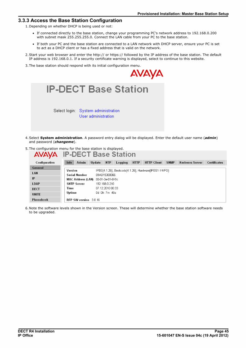
DECT R4 Installation Page 4515-601047 EN-S Issue 04c (19 April 2012)IP Office
Provisioned Installation: Master Base Station Setup
3.3.3 Access the Base Station Configuration1.Depending on whether DHCP is being used or not:
· If connected directly to the base station, change your programming PC's network address to 192.168.0.200with subnet mask 255.255.255.0. Connect the LAN cable from your PC to the base station.
· If both your PC and the base station are connected to a LAN network with DHCP server, ensure your PC is setto act as a DHCP client or has a fixed address that is valid on the network.
2.Start your web browser and enter the http:// or https:// followed by the IP address of the base station. The defaultIP address is 192.168.0.1. If a security certificate warning is displayed, select to continue to this website.
3.The base station should respond with its initial configuration menu.
4.Select System administration. A password entry dialog will be displayed. Enter the default user name (admin)and password (changeme).
5.The configuration menu for the base station is displayed.
6.Note the software levels shown in the Version screen. These will determine whether the base station software needsto be upgraded.

DECT R4 Installation Page 4615-601047 EN-S Issue 04c (19 April 2012)IP Office
3.3.4 Set the Base Station IP AddressBy default a base station defaults to 192.168.0.1. The process below can be used to change the DHCP mode and IPaddress of the base station.
1.Having browsed into the base station's configuration, in the left-hand column select LAN.
2.Select the IP tab.
a. Enter the required IP Address and Network Mask for the base station. The other settings are optional.
b.Click OK.
3.Select the DHCP tab.
a.Using the Mode drop-down, select Disabled.
b.Click OK.
4.The menu will prompt you with the message Reset Required. Do not click this or reset the base station at thisstage.
a.Select Reset and then select the Reset tab.
b.Click on OK.
c. Observing the base station, wait for the lower light to return to solid green.
5.Log in again using the new IP address.

DECT R4 Installation Page 4715-601047 EN-S Issue 04c (19 April 2012)IP Office
Provisioned Installation: Master Base Station Setup
3.3.5 Update the Base Station SoftwareThe base station may need to be upgraded to the software supplied for use with IP Office administration software. Thatsoftware consists of two parts, a firmware file and a boot file. All base stations in a DECT system should use the samesoftware.
1.Browse into the base station's configuration and note the software levels shown by the Version line.
· Check that these match the versions supplied with the IP Office administration software. Ensure that you arechecking against the correct folder for an IPBS1 or IPBS2 base station. If they do not not match, then the basestation should be upgraded.
· If both software files need to be upgraded, the boot file should be upgraded first.
2.To upgrade the boot file, in the left-hand column select Update and then select the Boot tab. To upgrade the basestation file, select Update and then select the Firmware tab. The method for both files is similar, however ensureyou upgrade the boot file first if both need to be upgraded.
3.Click on the Choose File button and browse to the IP Base Station sub-folder of the IP DECT R4 software youpreviously extracted onto the programming PC.
4.Select the appropriate file for the upgrade you are performing, ie. the file with boot in the file name if doing a bootfile upgrade. Click OK.
5.Click on the Upload button.
6.The browser will show the progress of the upload and firmware upgrade. It will indicate when the process has beencompleted.

DECT R4 Installation Page 4815-601047 EN-S Issue 04c (19 April 2012)IP Office
7.Click on immediate reset.
8.Login in again. The General | Info tab should now list the new firmware.
9.If necessary, repeat the process for the firmware using the Update | Firmware menu.
10.For a IP DECT Gateway, if necessary also repeat the process for base station firmware for base stations that will beconnected to the IP DECT Gateway using the Update | RFPs menu.

DECT R4 Installation Page 4915-601047 EN-S Issue 04c (19 April 2012)IP Office
Provisioned Installation: Master Base Station Setup
3.3.6 Select Simplified AdministrationBy default all base station menus and menu options are visible, including numerous settings that are not applicable for IPOffice operation. By turning off advanced options, only those menus and settings applicable to IP Office mode are shown.While this is not necessary for installation it is recommended.
This process is not necessary on the Compact Base Station which have advanced options hidden by default. This option isnot supported on a IP DECT Gateway.
1.Select General | Admin.
2.Deselect Show Advanced Options.
3.Click OK.
a.Select Reset and then select the Reset tab.
b.Click on OK.
c. Observing the base station, wait for the lower light to return to solid green.

DECT R4 Installation Page 5015-601047 EN-S Issue 04c (19 April 2012)IP Office
3.3.7 Set the DECT Password
1.Select DECT and then select the System tab.
2.Enter and confirm the password you want to use.
3.The Subscriptions and Authentication Code fields should not be adjusted. These will be set by the IP Office onethe base station is in provisioning mode.
4.Check that the Frequency field is set correctly for your location.
5.Click OK.
a.Select Reset and then select the Reset tab.
b.Click on OK.
c. Observing the base station, wait for the lower light to return to solid green.
3.3.8 Select Master ModeThe base station needs to be told to act as a master base station and needs to be told what type of telephone system itwill be operating with.
1.Select DECT and then select the Master tab.
2.Change the Mode to Active and click OK.
3.Reset the base station.
a.Select Reset and then select the Reset tab.
b.Click on OK.
c. Observing the base station, wait for the lower light to return to solid green.

DECT R4 Installation Page 5115-601047 EN-S Issue 04c (19 April 2012)IP Office
Provisioned Installation: Master Base Station Setup
4.Select DECT and then select the Master tab again.
5.Change the PBX setting to IPO and click OK.
6.Reset the base station.
d.Select Reset and then select the Reset tab.
e. Click on OK.
f. Observing the base station, wait for the lower light to return to solid green.
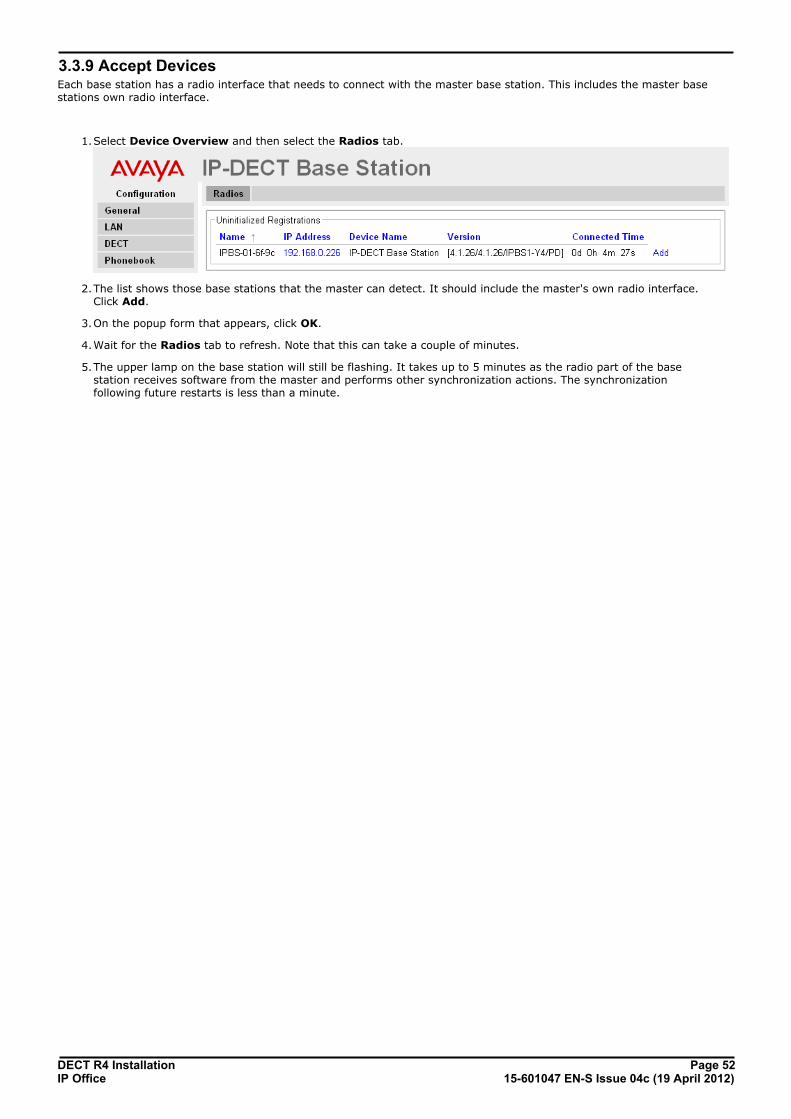
DECT R4 Installation Page 5215-601047 EN-S Issue 04c (19 April 2012)IP Office
3.3.9 Accept DevicesEach base station has a radio interface that needs to connect with the master base station. This includes the master basestations own radio interface.
1.Select Device Overview and then select the Radios tab.
2.The list shows those base stations that the master can detect. It should include the master's own radio interface.Click Add.
3.On the popup form that appears, click OK.
4.Wait for the Radios tab to refresh. Note that this can take a couple of minutes.
5.The upper lamp on the base station will still be flashing. It takes up to 5 minutes as the radio part of the basestation receives software from the master and performs other synchronization actions. The synchronizationfollowing future restarts is less than a minute.

DECT R4 Installation Page 5315-601047 EN-S Issue 04c (19 April 2012)IP Office
Provisioned Installation: Master Base Station Setup
3.3.10 Enable ProvisioningThe master base station can now be configured for IP Office provisioning. Once this is enabled, several fields of the basestation configuration will be set by the IP Office system. Other fields are greyed out and or automatically set to the valuesrequired for IP Office operation.
1.Select General and then select the Provisioning tab. This tab is only available when the base station's Mastersetting is Active and the PBX setting is set to IPO (see Select Master Mode ).
· Select the Enable option.
· The IP Office security settings control whether HTTPS is supported between the IP Office control unit andthe master base station (by default it is supported).
· Set the PBX IP Address to match the IP Office system on which the IP DECT line was configured.
2.Click OK.
3.Reset the base station.
a.Select Reset and then select the Reset tab.
b.Click on OK.
c. Observing the base station, wait for the lower light to return to solid green.
4.Select the General | Provisioning tab again. The Status should have changed to Connected.
5.Select DECT | SARI. The value of the SARI entered into the IP Office configuration should now also be visible in thebase station configuration.
6.Select DECT | System. The message System in Provisioning Mode is shown. The Subscriptions mode is greyed outand set to With System AC. The Authentication Code will match the one set in the IP Office configuration.
50
36

DECT R4 Installation Page 5415-601047 EN-S Issue 04c (19 April 2012)IP Office
3.3.11 Phonebook IntegrationIn an IP Office provisioned installation, the phonebook settings are automatically set by the IP Office system. However useof IP Office users, groups and directory as part of the DECT phone directory still needs to be enabled if required. If notenabled, the Central Phonebook functions on the DECT phones will not work. For DECT systems using an AIWS, centralphone book provision is done via the AIWS.
1.Select Phonebook.
2.Select Enable.
3.4 IP Slave Base Station SetupThe slave base station configuration for a provision installation consists of the following steps:
1.Default the Base Station .
2.Determine the Base Station IP Address .
3.Access the Base Station Configuration .
4.Set the Base Station IP Address .
5.Update the Base Station Software .
55
55
56
57
58

DECT R4 Installation Page 5515-601047 EN-S Issue 04c (19 April 2012)IP Office
Provisioned Installation: IP Slave Base Station Setup
3.4.1 Defaulting the Base StationThis process will default a base station or IP DECT Gateway, erasing its configuration. After the unit restarts it will defaultto the IP address 192.168.0.1/255.255.255.0.
1.With the unit not connected to anything else, connect the power supply and switch on.
2.Wait approximately 5 seconds.
3.Using a fine point, depress the unit's reset switch for at least 10 seconds.
4.Release the switch. The unit will restart.
5.After approximately 5 seconds the unit will default to the address 192.168.0.1.
3.4.2 Determining the Base Station IP AddressThe address an existing base station or IP DECT Gateway is using can be determined using the following process. It usesthe MAC address of the unit which is printed on a label on the back or bottom of the unit.
1.Open a Windows command window by selecting Start | Run and enter cmd.
2.Enter nbtstat -R. The PC should respond that is has purged and reloaded the NBT remote cache table.
3.For a base station enter nbtstat -a ipbs-xx-xx-xx when xx-xx-xx is replaced with the last 6 hexadecimal digits ofthe base stations MAC address. For a IP DECT Gateway, enter nbtstat -a ipbl-xx-xx-xx.
4.The results will show the IP address which it being used.
4.Use that address to access the base stations configuration and set it to a fixed address.

DECT R4 Installation Page 5615-601047 EN-S Issue 04c (19 April 2012)IP Office
3.4.3 Access the Base Station Configuration1.Depending on whether DHCP is being used or not:
· If connected directly to the base station, change your programming PC's network address to 192.168.0.200with subnet mask 255.255.255.0. Connect the LAN cable from your PC to the base station.
· If both your PC and the base station are connected to a LAN network with DHCP server, ensure your PC is setto act as a DHCP client or has a fixed address that is valid on the network.
2.Start your web browser and enter the http:// or https:// followed by the IP address of the base station. The defaultIP address is 192.168.0.1. If a security certificate warning is displayed, select to continue to this website.
3.The base station should respond with its initial configuration menu.
4.Select System administration. A password entry dialog will be displayed. Enter the default user name (admin)and password (changeme).
5.The configuration menu for the base station is displayed.
6.Note the software levels shown in the Version screen. These will determine whether the base station software needsto be upgraded.

DECT R4 Installation Page 5715-601047 EN-S Issue 04c (19 April 2012)IP Office
Provisioned Installation: IP Slave Base Station Setup
3.4.4 Set the Base Station IP AddressBy default a base station defaults to 192.168.0.1. The process below can be used to change the DHCP mode and IPaddress of the base station.
1.Having browsed into the base station's configuration, in the left-hand column select LAN.
2.Select the IP tab.
a. Enter the required IP Address and Network Mask for the base station. The other settings are optional.
b.Click OK.
3.Select the DHCP tab.
a.Using the Mode drop-down, select Disabled.
b.Click OK.
4.The menu will prompt you with the message Reset Required. Do not click this or reset the base station at thisstage.
a.Select Reset and then select the Reset tab.
b.Click on OK.
c. Observing the base station, wait for the lower light to return to solid green.
5.Log in again using the new IP address.

DECT R4 Installation Page 5815-601047 EN-S Issue 04c (19 April 2012)IP Office
3.4.5 Update the Base Station SoftwareThe base station may need to be upgraded to the software supplied for use with IP Office administration software. Thatsoftware consists of two parts, a firmware file and a boot file. All base stations in a DECT system should use the samesoftware.
1.Browse into the base station's configuration and note the software levels shown by the Version line.
· Check that these match the versions supplied with the IP Office administration software. Ensure that you arechecking against the correct folder for an IPBS1 or IPBS2 base station. If they do not not match, then the basestation should be upgraded.
· If both software files need to be upgraded, the boot file should be upgraded first.
2.To upgrade the boot file, in the left-hand column select Update and then select the Boot tab. To upgrade the basestation file, select Update and then select the Firmware tab. The method for both files is similar, however ensureyou upgrade the boot file first if both need to be upgraded.
3.Click on the Choose File button and browse to the IP Base Station sub-folder of the IP DECT R4 software youpreviously extracted onto the programming PC.
4.Select the appropriate file for the upgrade you are performing, ie. the file with boot in the file name if doing a bootfile upgrade. Click OK.
5.Click on the Upload button.
6.The browser will show the progress of the upload and firmware upgrade. It will indicate when the process has beencompleted.

DECT R4 Installation Page 5915-601047 EN-S Issue 04c (19 April 2012)IP Office
Provisioned Installation: IP Slave Base Station Setup
7.Click on immediate reset.
8.Login in again. The General | Info tab should now list the new firmware.
9.If necessary, repeat the process for the firmware using the Update | Firmware menu.
10.For a IP DECT Gateway, if necessary also repeat the process for base station firmware for base stations that will beconnected to the IP DECT Gateway using the Update | RFPs menu.
Repeat the steps above for any other base stations that are also being installed. All the base stations should use the samefirmware.

DECT R4 Installation Page 6015-601047 EN-S Issue 04c (19 April 2012)IP Office
3.4.6 Register the Slave Base StationThe slave base station needs to register and be synchronized with the master base station. This is done in the master basestation configuration.
1.Login to the master base station.
2.Select Device Overview and then select the Radios tab.
3.The new slave base station is shown as an unregistered device. Click on Add.
4.On the popup form that appears, click OK.
5.The slave base station will be listed as a registered device. It can take up to 2 minutes for the base station tosynchronize with the master base station. During this time its upper lamp will flash red and the status shows as Notin sync . Once it is in synch, the upper lamp is extinguished and the status is shown as OK.
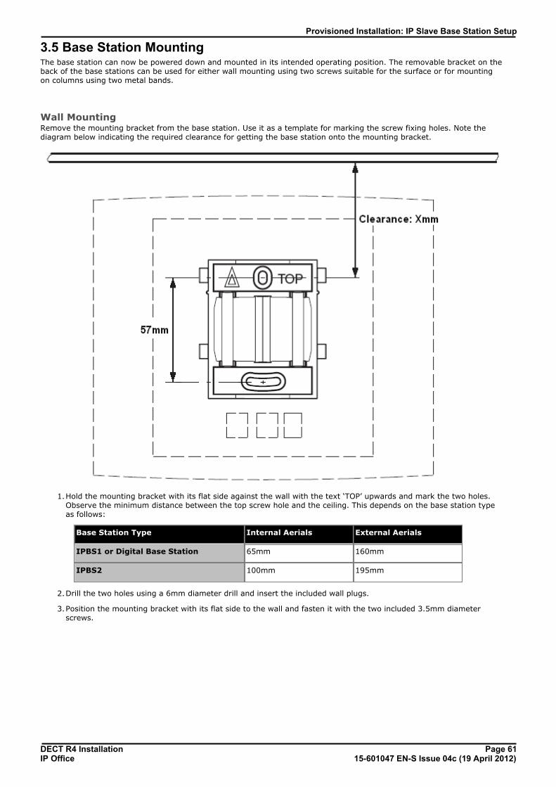
DECT R4 Installation Page 6115-601047 EN-S Issue 04c (19 April 2012)IP Office
Provisioned Installation: IP Slave Base Station Setup
3.5 Base Station MountingThe base station can now be powered down and mounted in its intended operating position. The removable bracket on theback of the base stations can be used for either wall mounting using two screws suitable for the surface or for mountingon columns using two metal bands.
Wall MountingRemove the mounting bracket from the base station. Use it as a template for marking the screw fixing holes. Note thediagram below indicating the required clearance for getting the base station onto the mounting bracket.
1.Hold the mounting bracket with its flat side against the wall with the text ‘TOP’ upwards and mark the two holes.Observe the minimum distance between the top screw hole and the ceiling. This depends on the base station typeas follows:
Base Station Type Internal Aerials External Aerials
IPBS1 or Digital Base Station 65mm 160mm
IPBS2 100mm 195mm
2.Drill the two holes using a 6mm diameter drill and insert the included wall plugs.
3.Position the mounting bracket with its flat side to the wall and fasten it with the two included 3.5mm diameterscrews.
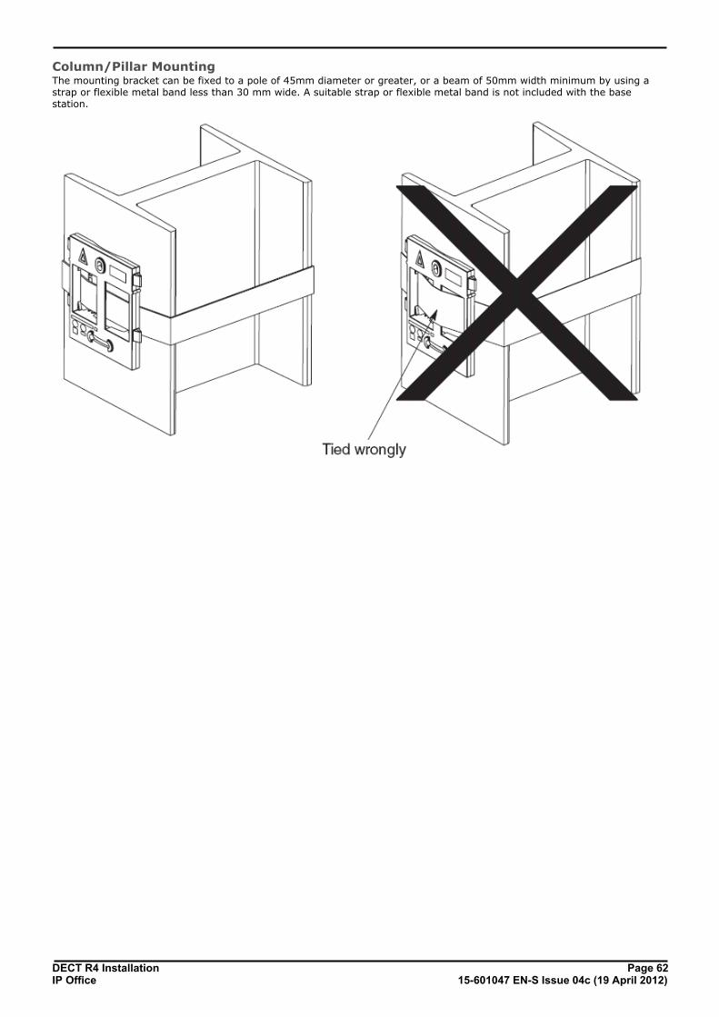
DECT R4 Installation Page 6215-601047 EN-S Issue 04c (19 April 2012)IP Office
Column/Pillar MountingThe mounting bracket can be fixed to a pole of 45mm diameter or greater, or a beam of 50mm width minimum by using astrap or flexible metal band less than 30 mm wide. A suitable strap or flexible metal band is not included with the basestation.

DECT R4 Installation Page 6315-601047 EN-S Issue 04c (19 April 2012)IP Office
Provisioned Installation: Base Station Mounting
3.6 Phone SubscriptionThere are two methods of phone subscription; pre-configured or anonymous.
In both cases, the IP Office configuration should also contain available Avaya IP Endpoint Licenses . The PARK codeand Authentication Code of the DECT R4 system are required during subscription. The values set on the IP DECT line in theIP Office configuration are used.
Anonymous Phone SubscriptionThis method is used when the IP Office IP DECT line's Subscriptions setting is set to Auto-Create. After successfullysubscribing, the phone is assigned a temporary extension number just about the highest existing extension number. Thiscan either be accepted or another extension number specified.
· Subscription Using IP Office Auto-Create Allowing phone subscription using the IP Office auto-create options for extensions and or users makeschanges to the current running configuration of the IP Office system. For this method to work, youmust ensure that no copies of the configuration are also open in Manager during subscription, assending such a copy of the configuration back to the IP Office system will replace the subscriptionsand require the handsets to be subscribed again. Following any handset subscription, a new copy ofthe configuration should always be loaded in IP Office Manager if any other configuration changes arerequired.
1.Set the IP DECT line's Subscriptions mode to Auto-Create. Ensure that the Auto-Create User and Auto-CreateExtension options are also selected.
2.Subscribe the phone to a temporary extension number .
3.Accept the temporary extension number ( *# ) or enter an alternate extension number ( XXX * LLL# ) .
4.Disable subscription when all phones have been subscribed .
Preconfigured Phone SubscriptionThis method is used when the IP Office IP DECT line's Subscriptions setting is set to Preconfigured. The SARI andAuthentication Code set in the IP Office configuration are used. Using this method, entries for the IP DECT extensions andusers must first be created in the IP Office configuration. The matching phones can then be subscribed.
1.Set the IP DECT line's Subscriptions mode to Preconfigured.
2.Create an IP DECT extension and user entry for each phone .
3.Subscribe the phones .
4.Disable subscription when all phones have been subscribed .
Requirements
Information· Service user name and password for IP Office configuration.
· User names and extension numbers for the DECT phones.
· Phone IPEI numbers if using an pre-configured installation mode.
Tools· IP Office Manager.
· Device Manager The software installed on each handset may need to be upgraded to match that supplied with the DECT R4 software
. This is done using the Windows Device Manager software to upgrade phones via an advanced charger orusing AIWS Device Manager to upgrade phones over the air.
· Web browser (Internet Explorer or Firefox are supported).
41
70
70 70 70 70 70
70 70 70
75
69
70
75
34
95

DECT R4 Installation Page 6415-601047 EN-S Issue 04c (19 April 2012)IP Office
3.6.1 Install Windows Device ManagerIt may be necessary to upgrade to software used by the 3720, 3725, 3740 and 3749 phones. For new installations it isassumed that the Windows Device Manager and advanced chargers will be used for this.
1.Browse to the location where you unpacked the IP Office software for DECT R4. Locate the folder Avaya WinPDM.
2.Double-click on Setup.exe.
3.Click Next.

DECT R4 Installation Page 6515-601047 EN-S Issue 04c (19 April 2012)IP Office
Provisioned Installation: Phone Subscription
4.Select Avaya WinPDM and click Next.
5.Click Install.
6.When the installation is completed, click on Finish.
3.6.2 Loading Parameter Definition FilesThe parameter definition files supplied with the DECT R4 software include software files used to update the phonesoftware. These files must be uploaded to WinPDM in order to allow phones to be upgraded.
1.Start the AIWS Device Manager or Windows Device Manager . 95 95

DECT R4 Installation Page 6615-601047 EN-S Issue 04c (19 April 2012)IP Office
2.Select File | File management.
3.Select the Parameter definition tab.
4.Click Add.... Browse to the Handsets folder in the software previous unpacked. Select the .pkg files in the folderand click Open.

DECT R4 Installation Page 6715-601047 EN-S Issue 04c (19 April 2012)IP Office
Provisioned Installation: Phone Subscription
5.Click Add... again. Browse to the Chargers folder in the software previous unpacked. Select the .pkg files in thefolder and click Open.
6.The list of parameter definition files should now be complete.
7.Select Close.

DECT R4 Installation Page 6815-601047 EN-S Issue 04c (19 April 2012)IP Office
3.6.3 Enabling SubscriptionThe IP DECT line settings control whether DECT handsets are able to subscribe.
1.Using IP Office Manager, receive the configuration from the IP Office system.
2.Click on Line. The list of existing lines is shown.
3.Click on the icon and select IP DECT Line. The settings for an IP DECT line are displayed. If the option is greyedout then the configuration already contains an IP DECT line.
3.The Line tab will list any DECT extensions already subscribed.
4.Select the Gateway tab.
5.Note the values set in the SARI/PARK and Authentication Code fields. These values are used during the phonesubscription.
6.Change the Subscriptions mode to either Auto-Create or Preconfigured.
· Auto-Create If you select this option, extension and user entries are automatically created in the IP Office configurationwhen the handsets are subscribed. Use this option for anonymous subscription. Ensure that
· Preconfigured If you select this option, handset will only be able to subscribe if they match an existing IP DECT extensionin the IP Office configuration.
7.Save the configuration back to the IP Office system.

DECT R4 Installation Page 6915-601047 EN-S Issue 04c (19 April 2012)IP Office
Provisioned Installation: Phone Subscription
3.6.4 Manually Creating ExtensionsIf the IP DECT line's subscription setting is set to Preconfigured, you must manually add extension and user entries foreach handset to the IP Office configuration.
1.Using IP Office Manager, receive the configuration from the IP Office system.
2.Click on Extension.
3.Click on the icon and select IP DECT Extension. This option is greyed out until an IP DECT line is added to theconfiguration.
4.Select the Extn tab. Set the Base Extension number to a currently unused extension number.
5.Select the IP DECT tab. Note that the appearance of this tab varies depend on whether the IP DECT line hasEnable Provisioning selected or not, this example is for provisioning enabled.
a.Set the Message Waiting Lamp Indication Type to On. For
b.Select the Reserved Avaya IP endpoint license option. This option will be greyed out if there are insufficientlicenses. If this option is selected, the phone will be licensed before any other Avaya IP endpoints for which thisoption has not be set.
c. Set the IPEI to match that of the handset. For new phones the IPEI is shown on the screen. For other phones itcan be displayed by selecting Menu | Settings | Device Info | IPEI/IPDI. It is also shown on a label underthe battery.
· For 3720, 3725, 3740 and 3749 phones, the IPEI can be displayed by selecting Menu | Settings |Device Info | IPEI/IPDI. It is also printed on a label under the phone's battery.
d. If Use Handset Configuration. is selected, the handset user is able to set the phone language and date/timeformat. If not seelcted, those settings will be driven by the system or user locale settings in the IP Officeconfiguration.
6.Click OK.
7. IP Office Manager will prompt whether you want to create an associated user. Select Yes.
8.The user settings are displayed. Adjust any of these if required and click OK.
9.Repeat the process to create any other extension and user entries required. Then save the configuration back to theIP Office system.
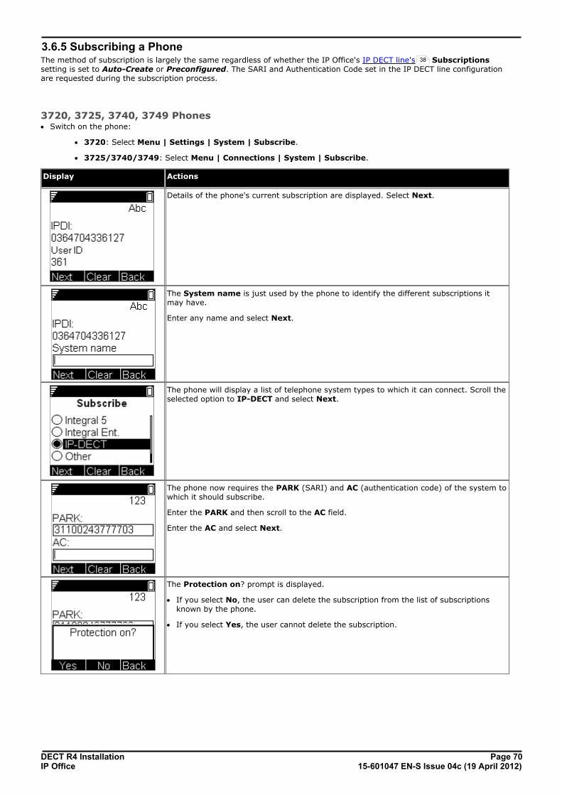
DECT R4 Installation Page 7015-601047 EN-S Issue 04c (19 April 2012)IP Office
3.6.5 Subscribing a PhoneThe method of subscription is largely the same regardless of whether the IP Office's IP DECT line's Subscriptionssetting is set to Auto-Create or Preconfigured. The SARI and Authentication Code set in the IP DECT line configurationare requested during the subscription process.
3720, 3725, 3740, 3749 Phones· Switch on the phone:
· 3720: Select Menu | Settings | System | Subscribe.
· 3725/3740/3749: Select Menu | Connections | System | Subscribe.
Display Actions
Details of the phone's current subscription are displayed. Select Next.
The System name is just used by the phone to identify the different subscriptions itmay have.
Enter any name and select Next.
The phone will display a list of telephone system types to which it can connect. Scroll theselected option to IP-DECT and select Next.
The phone now requires the PARK (SARI) and AC (authentication code) of the system towhich it should subscribe.
Enter the PARK and then scroll to the AC field.
Enter the AC and select Next.
The Protection on? prompt is displayed.
· If you select No, the user can delete the subscription from the list of subscriptionsknown by the phone.
· If you select Yes, the user cannot delete the subscription.
38

DECT R4 Installation Page 7115-601047 EN-S Issue 04c (19 April 2012)IP Office
Provisioned Installation: Phone Subscription
Display Actions
A summary of the subscription details is shown. Check that the values are correct
Select OK.
The phone broadcast for DECT systems to which it can subscribe.
When a DECT system is located, the handset will attempt to subscribe to that system.
The success or failure of the subscription is indicated.
The display shown after successful subscription will depend on whether anonymous subscription is being used or thephone matches an existing extension in the IP Office configuration.
Auto-Create Subscription Mode
If the phone display Enter New Login, it has been assigned a temporary extensionnumber, shown in brackets. The temporary number is simply the highest existingextension number plus 1.
· To accept the temporary extension number as permanent, dial *# and make thecall.
· To specify a different extension number, dial XXX*LLL# where XXX is theextension number to use and LLL is the Login Code to assign to the user.
· To accept the temporary extension as permanent but set a login code for theuser, dial *LLL# where LLL is the Login Code to assign to the user.

DECT R4 Installation Page 7215-601047 EN-S Issue 04c (19 April 2012)IP Office
Preconfigured Subscription Mode
If the phone's IPEI matches an existing extension entry in the IP Office configuration, thephone will use that extension's settings.
This may occur even when using anonymous subscription if the phone is an existingextensions re-subscribing to the system.
3701/3711 PhonesThis method is only supported if the IP DECT line's Subscriptions setting is set to Preconfigured and matchingconfiguration entries for the extensions have been created.
1.Switch on the phone.
2.Select Menu | System | Subscription | Subscribe HS.
3.Select PABX-PIN.
4.Enter the authentication code.

DECT R4 Installation Page 7315-601047 EN-S Issue 04c (19 April 2012)IP Office
Provisioned Installation: Phone Subscription
3.6.6 Upgrading PhonesDECT R4 is supported on a range of Avaya systems. However, for IP Office operation, only software specificallydocumented as having been tested and supported with IP Office should be used. Details of supported software for anyparticular IP Office release is included in IP Office Technical Bulletin for that release.
1.Start the AIWS Device Manager or Windows Device Manager .
2.Within the Avaya Device Manager, select the Devices tab.
3.The current software version of each phone is shown. Compare this to the software versions available, shown bythe version set as part of the .pkg file name included with the DECT R4 software .
4.In the device manager, select the phones that you want to upgrade.
5.Click Upgrade Software. The menu shown will depend on whether you are using the AIWS for an over the airupgrade or WinPDM for an in charger upgrade.
95 95
34

DECT R4 Installation Page 7415-601047 EN-S Issue 04c (19 April 2012)IP Office
· Advanced Charger/WinPDM Upgrade Menu This menu is shown when using the Windows based device manager to upgrade a phone currently in an advancedcharger connected to the PC by USB or LAN.
· AIWS Upgrade Software Menu This menu is shown when using the AIWS based device manager to upgrade phones over the air. This methodsupports a number of additional options but is much slower that upgrading phones in an advanced charger.
6.If you have already imported the parameter definition files for the phones, use the Available Files drop-down toselect the software bin file for the type of phone being upgraded. Otherwise click on Import and browse to the .pkgfiles for the phone type.
7.Select the other upgrade settings required and click OK.
DECT R4 Installation Page 7515-601047 EN-S Issue 04c (19 April 2012)IP Office
Provisioned Installation: Phone Subscription
3.6.7 Disabling SubscriptionSubscription can be disabled. This does not affect re-subscription by extensions that are already configured in the IP Officeconfiguration.
1.Using IP Office Manager, receive the configuration from the IP Office system.
2.Click on Line. The list of existing lines is shown.
3.Click on the icon and select IP DECT Line. The settings for an IP DECT line are displayed. If the option is greyedout then the configuration already contains an IP DECT line.
4.Click on the Gateway tab.
5.Change the Subscriptions setting to Disabled.
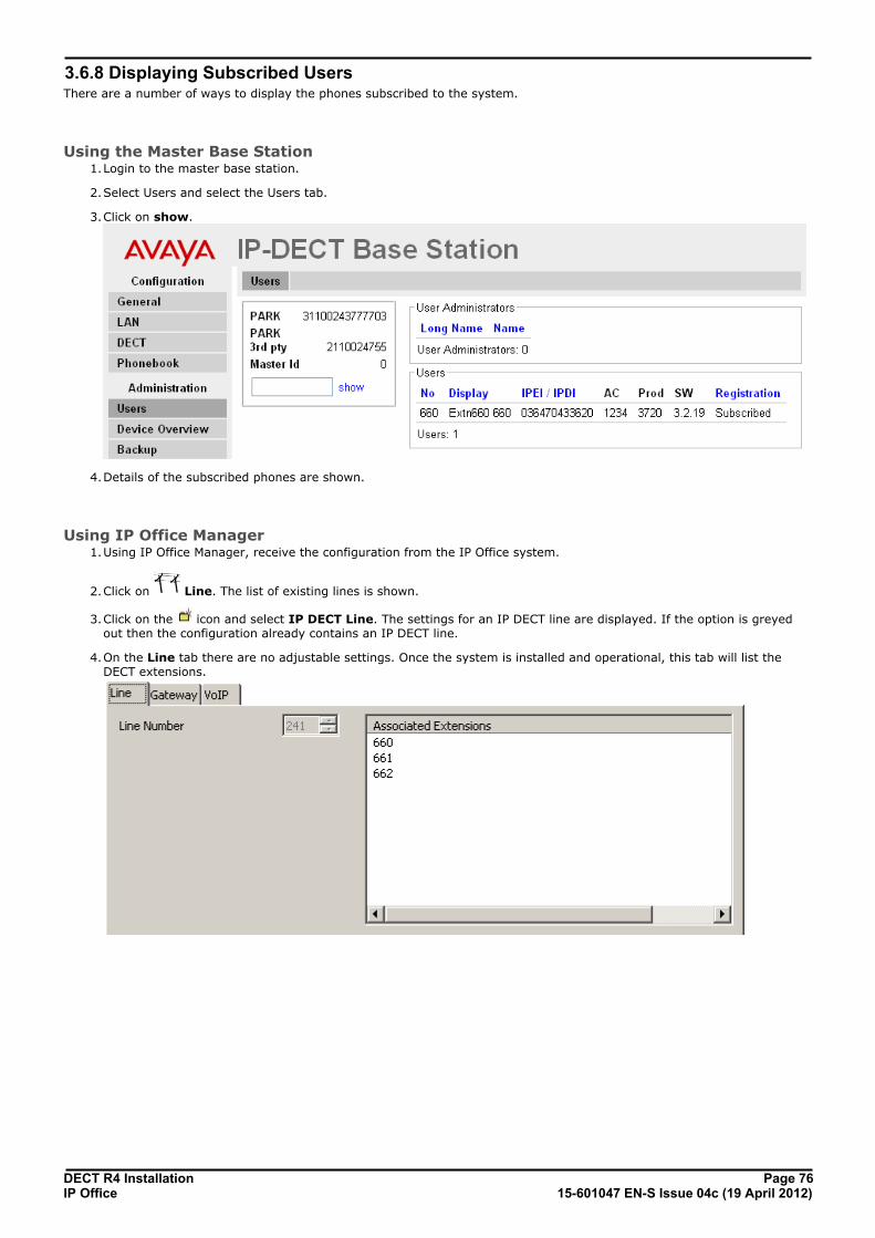
DECT R4 Installation Page 7615-601047 EN-S Issue 04c (19 April 2012)IP Office
3.6.8 Displaying Subscribed UsersThere are a number of ways to display the phones subscribed to the system.
Using the Master Base Station1.Login to the master base station.
2.Select Users and select the Users tab.
3.Click on show.
4.Details of the subscribed phones are shown.
Using IP Office Manager1.Using IP Office Manager, receive the configuration from the IP Office system.
2.Click on Line. The list of existing lines is shown.
3.Click on the icon and select IP DECT Line. The settings for an IP DECT line are displayed. If the option is greyedout then the configuration already contains an IP DECT line.
4.On the Line tab there are no adjustable settings. Once the system is installed and operational, this tab will list theDECT extensions.

DECT R4 Installation Page 7715-601047 EN-S Issue 04c (19 April 2012)IP Office
Provisioned Installation: Phone Subscription
Using the IP Office System Status ApplicationThe System Status application list DECT extensions as a subset of H.323 extensions. It can also be used to force theunsubscription of a phone.
3.6.9 Unsubscribing PhonesDECT phones can subscribe to multiple DECT systems and can then be switched between the system to which they arecurrently subscribed.
The Unsubscribe option provided through phone menus does not unsubscribe a phone from the DECT R4 system or IPOffice. It just removes details of the subscribed system from the phone. The Unsubscribe function only works forsubscriptions where the Protection option was set to No during the original subscription .
Resubscribing the phone reinstates the DECT R4 system in the list of systems of which the phone can select to becurrently subscribed.
To remove a phone from a system that is used IP Office provisioning, the phone's extension entry should be deleted fromthe IP Office configuration. To remove a phone from a system that is not using IP Office provisioning, the phone'sextension entry must be deleted from both the IP Office configuration and the master base station configuration.
70

DECT R4 Installation Page 7915-601047 EN-S Issue 04c (19 April 2012)IP Office
IP DECT Gateway Installation
Chapter 4.

DECT R4 Installation Page 8015-601047 EN-S Issue 04c (19 April 2012)IP Office
4. IP DECT Gateway InstallationBefore installation ensure that you have performed an assessment of the power consumption requirements of thedigital base stations. This will determine whether the base stations can be powered directly by the IP DECT Gateway oreach need their own separate power adapters. If powered using separate power adapters, the EPP power wires from the IPDECT Gateway should not also be connected.
IP DECT Gateway Installation SummaryThe configuration process for the IP DECT Gateway is very similar to that for an IP base station. In a new DECT R4 systeminstallation, we recommend that the IP DECT Gateway is installed as the master base station for the system. This does notaffect the allowed number of IP and or digital base stations.
The installation of a IP DECT Gateway as a master base station can be done as part of either a provisioned installationor non-provisioned installation installation. If the IP DECT Gateway is being added to an existing system, it can beadded in the same way as for a new slave base station.
A summary of the installation stages is as follows:
1.Install in rack.
2.Attach power cable.
3.Connect the unit to the LAN using the LAN 1 port.
4.Connect the digital base station cables.
5.Power on the unit.
6.Access and configure the unit in the same way as for a base station. The configuration required will depend onwhether the IP DECT Gateway is being used as a master base station for the system.
81
44
159

DECT R4 Installation Page 8115-601047 EN-S Issue 04c (19 April 2012)IP Office
IP DECT Gateway Installation:
4.1 Digital Base Station Power ConsumptionThe IP DECT Gateway can be used to power digital base stations via the same cable connection as used for signalling.However, the maximum power provision of the IP DECT Gateway is 15W and the power consumption of each digital basestation is dependent on the cable wire size and length. The table below indicates the power consumption and can be usedto calculate if the IP DECT Gateway can directly power the digital base stations. In cases where the IP DECT Gatewaycannot directly power all the digital base stations, some of the base stations will need a separate power connection.
Cable Lengthin Meters
0.4mm Wire Diameter 0.5mm Wire Diameter 0.6mm Wire Diameter
0 EPP 1 EPP 0 EPP 1 EPP 0 EPP 1 EPP
0 5.0 5.0 5.0 5.0 5.0 5.0
100 5.2 5.1 5.1 5.1 5.1 5.1
200 5.3 5.2 5.2 5.1 5.1 5.1
300 5.6 5.3 5.3 5.2 5.2 5.1
400 5.8 5.5 5.5 5.3 5.3 5.2
500 6.1 5.6 5.6 5.4 5.4 5.2
600 6.5 5.8 5.8 5.5 5.4 5.3
700 7.1 6.0 6.0 5.6 5.5 5.3
800 8.1 6.2 6.2 5.7 5.6 5.4
900 – 6.5 6.5 5.8 5.7 5.4
1000 – 6.9 6.9 5.9 5.8 5.5
1100 – 7.3 7.3 6.1 5.9 5.6
1200 – 8.1 8.1 6.2 6.1 5.6
1300 – – – 6.4 6.2 5.7
1400 – – – 6.6 6.4 5.8
1500 – – – 6.9 6.6 5.8
The following power supply adapters are available to power a base station locally. The maximum length of cable from theadapter to the base station must not exceed 10 meters.
· For European countries: Version 130137B.
· For the United Kingdom: Version 130136B.
· For the United States and Canada: Version 130138A.
· For Australia: Version 130139B.

DECT R4 Installation Page 8215-601047 EN-S Issue 04c (19 April 2012)IP Office
4.2 Installing the Digital Base StationsApart from the physical connection and power requirements, not configuration is required. The appropriate firmware filesare automatically provided to the base stations by the IP DECT Gateway.
Use the following cable pin-out to prepare the cable for connecting the digital base station to the IP DECT Gateway.Remember to allow sufficient cable length to allow for any potential repositioning of the base stations that may berequired.
BaseStation
Pin MDI(Crossover)
Wire Note
1 Power White/Orange On connection if using the IP DECT Gateway for power. Do not connectif powering the digital base station using a separate power supplyadapter. Refer to Digital Base Station Power Consumption . 2 Power. Orange/White
3 Date 1a. White/Green –
4 Data 0a. Blue/White –
5 Data 0b. White/Blue –
6 Data 1b. Green/White –
7 Not used. White/Brown –
8 Not used. Brown/White –
MountingThe base station can now be powered down and mounted in its intended operating position. The removable bracket on theback of the base stations can be used for either wall mounting using two screws suitable for the surface or for mountingon columns using two metal bands.
Wall MountingRemove the mounting bracket from the base station. Use it as a template for marking the screw fixing holes. Note thediagram below indicating the required clearance for getting the base station onto the mounting bracket.
81
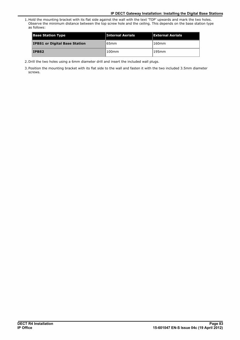
DECT R4 Installation Page 8315-601047 EN-S Issue 04c (19 April 2012)IP Office
IP DECT Gateway Installation: Installing the Digital Base Stations
1.Hold the mounting bracket with its flat side against the wall with the text ‘TOP’ upwards and mark the two holes.Observe the minimum distance between the top screw hole and the ceiling. This depends on the base station typeas follows:
Base Station Type Internal Aerials External Aerials
IPBS1 or Digital Base Station 65mm 160mm
IPBS2 100mm 195mm
2.Drill the two holes using a 6mm diameter drill and insert the included wall plugs.
3.Position the mounting bracket with its flat side to the wall and fasten it with the two included 3.5mm diameterscrews.

DECT R4 Installation Page 8415-601047 EN-S Issue 04c (19 April 2012)IP Office
Column/Pillar MountingThe mounting bracket can be fixed to a pole of 45mm diameter or greater, or a beam of 50mm width minimum by using astrap or flexible metal band less than 30 mm wide. A suitable strap or flexible metal band is not included with the basestation.
DECT R4 Installation Page 8515-601047 EN-S Issue 04c (19 April 2012)IP Office
IP Office User Features
Chapter 5.
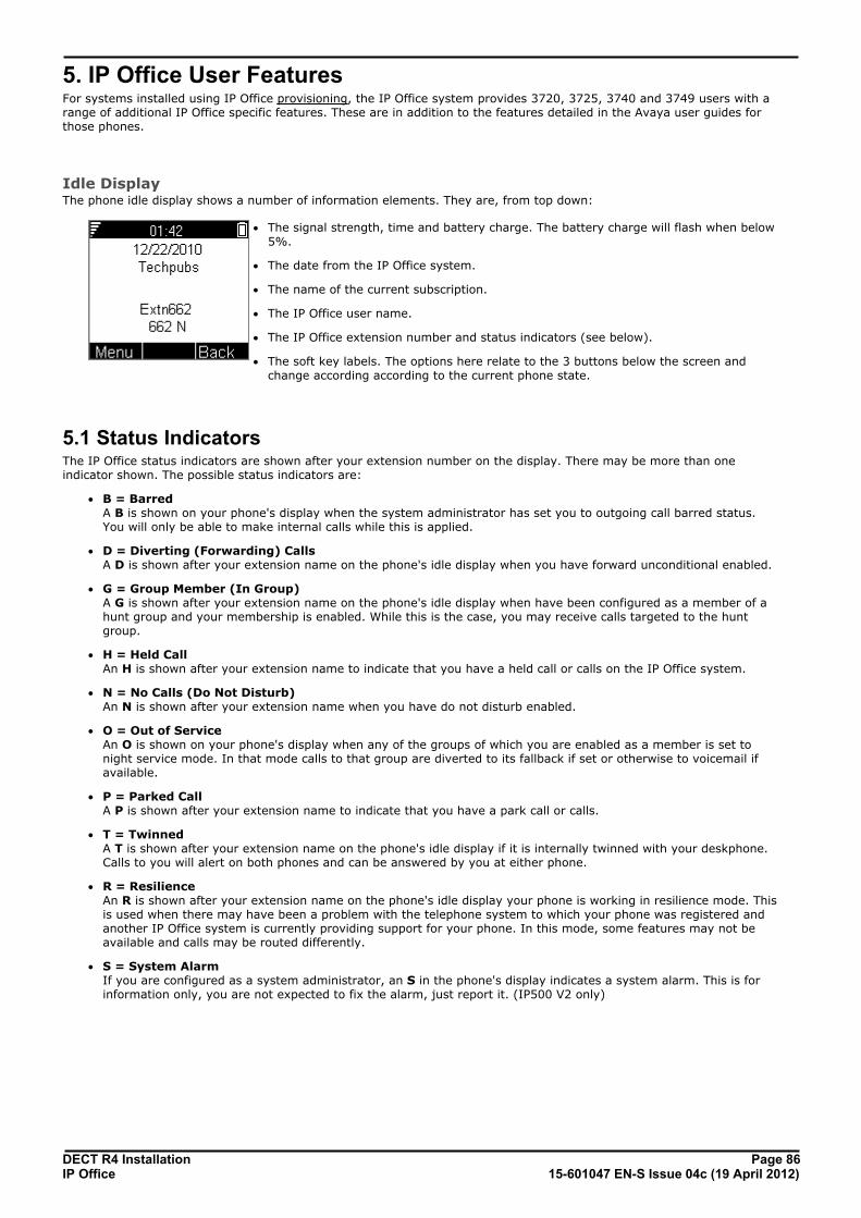
DECT R4 Installation Page 8615-601047 EN-S Issue 04c (19 April 2012)IP Office
5. IP Office User FeaturesFor systems installed using IP Office provisioning, the IP Office system provides 3720, 3725, 3740 and 3749 users with arange of additional IP Office specific features. These are in addition to the features detailed in the Avaya user guides forthose phones.
Idle DisplayThe phone idle display shows a number of information elements. They are, from top down:
· The signal strength, time and battery charge. The battery charge will flash when below5%.
· The date from the IP Office system.
· The name of the current subscription.
· The IP Office user name.
· The IP Office extension number and status indicators (see below).
· The soft key labels. The options here relate to the 3 buttons below the screen andchange according according to the current phone state.
5.1 Status IndicatorsThe IP Office status indicators are shown after your extension number on the display. There may be more than oneindicator shown. The possible status indicators are:
· B = Barred A B is shown on your phone's display when the system administrator has set you to outgoing call barred status.You will only be able to make internal calls while this is applied.
· D = Diverting (Forwarding) Calls A D is shown after your extension name on the phone's idle display when you have forward unconditional enabled.
· G = Group Member (In Group) A G is shown after your extension name on the phone's idle display when have been configured as a member of ahunt group and your membership is enabled. While this is the case, you may receive calls targeted to the huntgroup.
· H = Held Call An H is shown after your extension name to indicate that you have a held call or calls on the IP Office system.
· N = No Calls (Do Not Disturb) An N is shown after your extension name when you have do not disturb enabled.
· O = Out of Service An O is shown on your phone's display when any of the groups of which you are enabled as a member is set tonight service mode. In that mode calls to that group are diverted to its fallback if set or otherwise to voicemail ifavailable.
· P = Parked Call A P is shown after your extension name to indicate that you have a park call or calls.
· T = Twinned A T is shown after your extension name on the phone's idle display if it is internally twinned with your deskphone.Calls to you will alert on both phones and can be answered by you at either phone.
· R = Resilience An R is shown after your extension name on the phone's idle display your phone is working in resilience mode. Thisis used when there may have been a problem with the telephone system to which your phone was registered andanother IP Office system is currently providing support for your phone. In this mode, some features may not beavailable and calls may be routed differently.
· S = System Alarm If you are configured as a system administrator, an S in the phone's display indicates a system alarm. This is forinformation only, you are not expected to fix the alarm, just report it. (IP500 V2 only)

DECT R4 Installation Page 8715-601047 EN-S Issue 04c (19 April 2012)IP Office
IP Office User Features: Call Services
5.2 Call ServicesThe following options can be accessed when the phone is idle or the current call is parked or held.
1.Press Menu. Scroll the display to Calls and press Select.
2.Scroll down to Call services and press Select.
3.The list of available services is displayed. Scroll to the required service and press Select.
4.For some functions you may need to enter additional data on the display or select from a list. Do this and press OK.
5.The phone sends the appropriate signals to the IP Office.
6.Hang up the call.
The available services are:
· Call Pickup Any Answer the first available call ringing anywhere on the phone system (unless the call is on a private line). Details ofthe callers and the original call destination will be displayed.
· Call Pickup You can use this option to answer a call ringing at another extension. Select the option and enter the extensionnumber.
· Call UnPark Retrieve a call from the parked state. To do this you need to enter the park slot number assigned to the call when itwas parked. You can park a call using the Park Call option and assign it an park slot number at the same time thatyou or another user can then use to unpark the call.
· Call Waiting Suspend You can use this option to temporarily switch off call waiting . It will remain off until the end of your next call.Use this when you do not want a call interrupted by call waiting tones.
· Cancel All Fwd You can use this option to switch off all your call forwarding. It does not affect the forwarding numbers, just youruse of forwarding. If you have redirected your calls to another phone using follow me on that phone, this optionalso cancels the follow me.
· Do Not Disturb On Your can use this option to switch do not disturb on. Calls to you go to your voicemail mailbox if available,otherwise they receive busy. They do not follow any forwarding settings. A N for no calls is shown on the phone'sidle screen when you have do not disturb switched on.
· Some numbers can be configured as do not disturb exceptions. You can do this using the one-X Portal for IPOffice application or from the menu of some desk phones (contact your system administrator for details).Those numbers are able to call you and transfer calls to you while you have do not disturb switched on.
· Do Not Disturb Off You can use this option to switch do not disturb off. When off, calls will alert the handset and or follow yourforwarding settings.
· Fwd Unconditional On You can use this option to switch immediate call forwarding on. A forwarding number needs to be set for this towork, use the Fwd number call service to see and edit your current forwarding number. By default internal andexternal calls to you are forwarded but hunt group calls are not. However the settings for internal and hunt groupcalls can be adjusted by your system administrator. To switch off forwarding, use Cancel All Fwd.
· Fwd Busy On You can use this option to switch on forwarding of any additional calls when you are already have a call connected.If you have call waiting enabled, it is used for additional calls when you already have a call connected andanother one waiting. To switch off forwarding, use Cancel All Fwd.
· Fwd No Answer On You can use this option to forward any call that rings the handset without being answered. To switch off forwarding,use Cancel All Fwd.
· The default no answer time used to trigger the forward is 15 seconds. However this time can be adjusted byyour system administrator if required.
· If you use voicemail, the forward is used first. However if the call is still unanswered, the phone system will stillattempt to redirect the call to voicemail. This may not be possible for calls forwarded to external numbers.
90
90

DECT R4 Installation Page 8815-601047 EN-S Issue 04c (19 April 2012)IP Office
· Fwd Number You can use this option to see and set the number to which your calls are forwarded when you select FwdUnconditional On. If your system uses an external dialing prefix, remember to include it if you want to forwardcalls to an external number. However, note that external forwarding may be restricted by your systemadministrator. This number is also used for Fwd Busy On and Fwd No Answer On unless you set a separate FwdBusy Number.
· Fwd Busy Number You can use this option to see and set the number to which your calls are forwarded when you select Fwd Busy Onand or Fwd No Answer On. If your system uses an external dialing prefix, remember to include it if you want toforward calls to an external number. However, note that external forwarding may be restricted by your systemadministrator. To switch off forwarding, use Cancel All Fwd.
· Follow Me Here On If you are a temporary user of the phone, you can use this option to have calls to your desk phone redirected to thehandset. Select this option and enter your extension number.
· Follow Me Here Off To end a follow me set using Follow Me Here On, select this option and enter your extension number. Calls to thatnumber will no longer be redirected to the handset.
· Login Users with a login code can 'hot desk', that is login at any phone on the system and, when finished making ortaking calls, log out. While logged in on a phone, that phone adopts all their user settings and their calls are routedto it. This option can be used in a number of ways.
· The DECT handsets can be configured with no permanently associated user. To use the phone, you need tologin using your extension number and login code.
· The DECT handsets can be configured with an associated user. However, you can use log in and log out as amethod of security for your phone.
· Other users can use their log in code when they temporarily need to use your handset as their own phone.While they do this you are logged out.
· Note that SMS messaging, provided by the AIWS, always goes to the same original handset even when theassociate user hot desks to another handset.
· Logout If you have a login code, you can log out of the phone you are currently using. When you log out, if you arenormally associated with another phone, you are automatically logged back in on that phone unless someone else isusing it or you are set to forced login. If you are not automatically logged in elsewhere, then while logged out yourare treated as being busy to all calls. Instead your calls go to voicemail if available.

DECT R4 Installation Page 8915-601047 EN-S Issue 04c (19 April 2012)IP Office
IP Office User Features: Call Services
5.3 In Call OptionsDuring a call, the More soft key can be used to access a number of handset and IP Office functions while still remainingconnected to the call.
1.During the call, press More.
· If the phone is not currently on the call details screen, you may have to press Back to get to that screen beforeyou can press More.
2.Select the function required.
3.Some functions may require you to enter some data, for example the destination for a transfer.
The possible functions are:
· Auto Callback If you are making a call to another extension and it has not been answered, setting a callback tells the phonesystem to ring you when that extension finishes its next call. When you answer the target extension is rung again.
· Call Park You can use this option to park your current call. You can enter a park slot number which is then useable by anyoneelse on the system to unpark the call.
· If you do not enter a park slot number when parking a call, one is automatically assigned using your extensionnumber plus a digit 0 to 9.
· When you park a call, a P is shown on your phone's idle display until the call is unparked or the caller hangsup.
· Parked calls automatically re-ring you if left parked for too long (the default time is 5 minutes).
· Clear Call Use this option to end the current call and answer a held call. This may be useful when trying to transfer a held calland you find yourself connected to the transfer destinations voicemail or busy tone. Similarly you can use it whentrying to add another party to a conference if the other party does not answer or does not want to be part of theconference.
· Clear Call Waiting You can use this option to end your current call and automatically answer the waiting call.
· Conference You can use this option to start a conference with the current call and any calls you current have on hold. Theconference is automatically assigned a conference number that is shown on the display. To add another party to theconference, press R to put your connection to it on hold, dial the other party and when answered selectConference again.
· Conference Add You can use this option to turn your current call into a conference call. To add another party to the conference,press R to put your connection to it on hold, dial the other party and when answered select Conference again.
· Hold Call Waiting You can use this option to put your current call on hold and automatically answer the waiting call.
· Call Record You can use this option to switch on call recording if your phone system includes IP Office Voicemail Pro.
· Microphone Off
You can use this option to turn the handset's microphone off. A icon is displayed on the call details screen. Themicrophone is automatically re-enabled when you next make or answer a call.
· Microphone On You can use this option to turn the handset's microphone back on if you have turned it off during the call.
· Transfer You can use this option to put the call on hold and enter the number to which you want it transferred. You can thenhangup and the call is automatically transferred.

DECT R4 Installation Page 9015-601047 EN-S Issue 04c (19 April 2012)IP Office
5.4 Call Waiting OptionsBy default call waiting is turned on for all users. On the DECT display with a call already connected, another incoming callwill cause you to hear a single beep and the phone display will alternate between details of your current call and thewaiting call.
You can only have one connected call plus one waiting call. Any further calls will see you as being busy and will eitherfollow your forward on busy settings if set or else go to voicemail if available. If you don't answer the waiting call, it willfollow your forward on no answer settings if set or else go to voicemail.
If you end your current call while you have a call waiting, the waiting call will start ringing and can be answered. You canend your current call and automatically answer the waiting call by using the Clear Call Waiting option. You can holdyour current call and automatically answer the waiting call by using the Hold Call Waiting option.
90
90

DECT R4 Installation Page 9115-601047 EN-S Issue 04c (19 April 2012)IP Office
Device Management
Chapter 6.

DECT R4 Installation Page 9215-601047 EN-S Issue 04c (19 April 2012)IP Office
6. Device ManagementThis section covers the use of the Device Management application to update the firmware on the phones and to applycustomized features templates to the phones.
There are two variants of the device management application that can be used. They look similar and offer the similarfeatures but operate differently:
· AIWS Device Manager This is a version of the device manager application embedded into the AIWS unit. It can be started via browseraccess to the AIWS unit rather than having to be installed on a particular PC.
· WinPDM (Windows Portable Device Manager) This is a version of the device manager application that can be installed onto a Windows PC.
· The use of templates is not supported for systems installed and maintained using IP Office provisioning. Withprovisioned systems, device management should only be used for updating handset firmware.

DECT R4 Installation Page 9315-601047 EN-S Issue 04c (19 April 2012)IP Office
Device Management:
6.1 Installing Windows Device ManagerAs an alternative to the Device Manager application integrated into the AIWS unit, a copy of Windows Device Manager canbe installed onto a Windows PC (Windows XP or Vista).
1.Browse to the location where you unpacked the IP Office software for DECT R4. Locate the folder Avaya WinPDM.
2.Double-click on Setup.exe.
3.Click Next.

DECT R4 Installation Page 9415-601047 EN-S Issue 04c (19 April 2012)IP Office
4.Select Avaya WinPDM and click Next.
5.Click Install.
6.When the installation is completed, click on Finish.
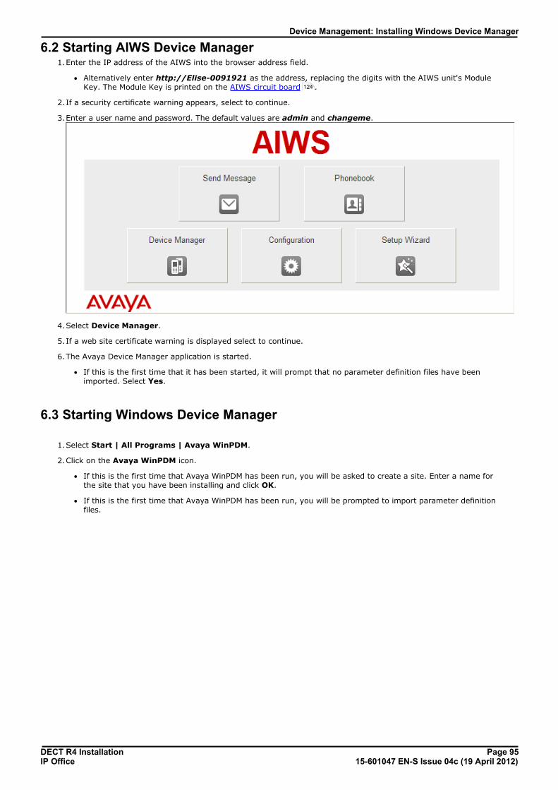
DECT R4 Installation Page 9515-601047 EN-S Issue 04c (19 April 2012)IP Office
Device Management: Installing Windows Device Manager
6.2 Starting AIWS Device Manager1.Enter the IP address of the AIWS into the browser address field.
· Alternatively enter http://Elise-0091921 as the address, replacing the digits with the AIWS unit's ModuleKey. The Module Key is printed on the AIWS circuit board .
2.If a security certificate warning appears, select to continue.
3.Enter a user name and password. The default values are admin and changeme.
4.Select Device Manager.
5. If a web site certificate warning is displayed select to continue.
6.The Avaya Device Manager application is started.
· If this is the first time that it has been started, it will prompt that no parameter definition files have beenimported. Select Yes.
6.3 Starting Windows Device Manager
1.Select Start | All Programs | Avaya WinPDM.
2.Click on the Avaya WinPDM icon.
· If this is the first time that Avaya WinPDM has been run, you will be asked to create a site. Enter a name forthe site that you have been installing and click OK.
· If this is the first time that Avaya WinPDM has been run, you will be prompted to import parameter definitionfiles.
124

DECT R4 Installation Page 9615-601047 EN-S Issue 04c (19 April 2012)IP Office
6.4 Load Parameter Definition FilesThe parameter definition files supplied with the DECT R4 software include software files used to update the phonesoftware. These files must be uploaded to WinPDM in order to allow phones to be upgraded.
1.Start the AIWS Device Manager or Windows Device Manager .
2.Select File | File management.
3.Select the Parameter definition tab.
4.Click Add.... Browse to the Handsets folder in the software previous unpacked. Select the .pkg files in the folderand click Open.
95 95

DECT R4 Installation Page 9715-601047 EN-S Issue 04c (19 April 2012)IP Office
Device Management: Load Parameter Definition Files
5.Click Add... again. Browse to the Chargers folder in the software previous unpacked. Select the .pkg files in thefolder and click Open.
6.The list of parameter definition files should now be complete.
7.Select Close.

DECT R4 Installation Page 9815-601047 EN-S Issue 04c (19 April 2012)IP Office
6.5 Loading Phone Templates into Device ManagerTemplates allow you to apply common settings to phones and chargers. The IP Office DECT R4 software set includesdefault templates for 3720, 3725, 3740 and 3749 phones that allow those phones to access IP Office functions throughthe phone menus.
· The use of templates is not supported for systems installed and maintained using IP Office provisioning. Withprovisioned systems, device management should only be used for updating handset firmware.
1.Start the AIWS Device Manager or Windows Device Manager .
2.Select the Devices tab. The phones subscribed to the DECT system should be listed.
3.Select File | Import | Templates... .
95 95

DECT R4 Installation Page 9915-601047 EN-S Issue 04c (19 April 2012)IP Office
Device Management: Loading Phone Templates into Device Manager
4.Browse to the previously unpacked software and select the .tpl template files.
5.Click Open. The template files are loaded into Avaya Device Manager.
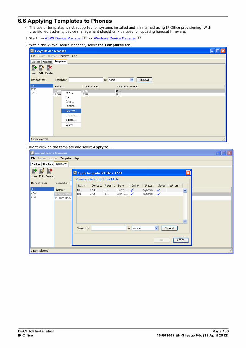
DECT R4 Installation Page 10015-601047 EN-S Issue 04c (19 April 2012)IP Office
6.6 Applying Templates to Phones· The use of templates is not supported for systems installed and maintained using IP Office provisioning. With
provisioned systems, device management should only be used for updating handset firmware.
1.Start the AIWS Device Manager or Windows Device Manager .
2.Within the Avaya Device Manager, select the Templates tab.
3.Right-click on the template and select Apply to....
95 95

DECT R4 Installation Page 10115-601047 EN-S Issue 04c (19 April 2012)IP Office
Device Management: Applying Templates to Phones
4.Select the phones to which you want the template to be applied. Click OK. The phones will begin uploading thetemplate file.
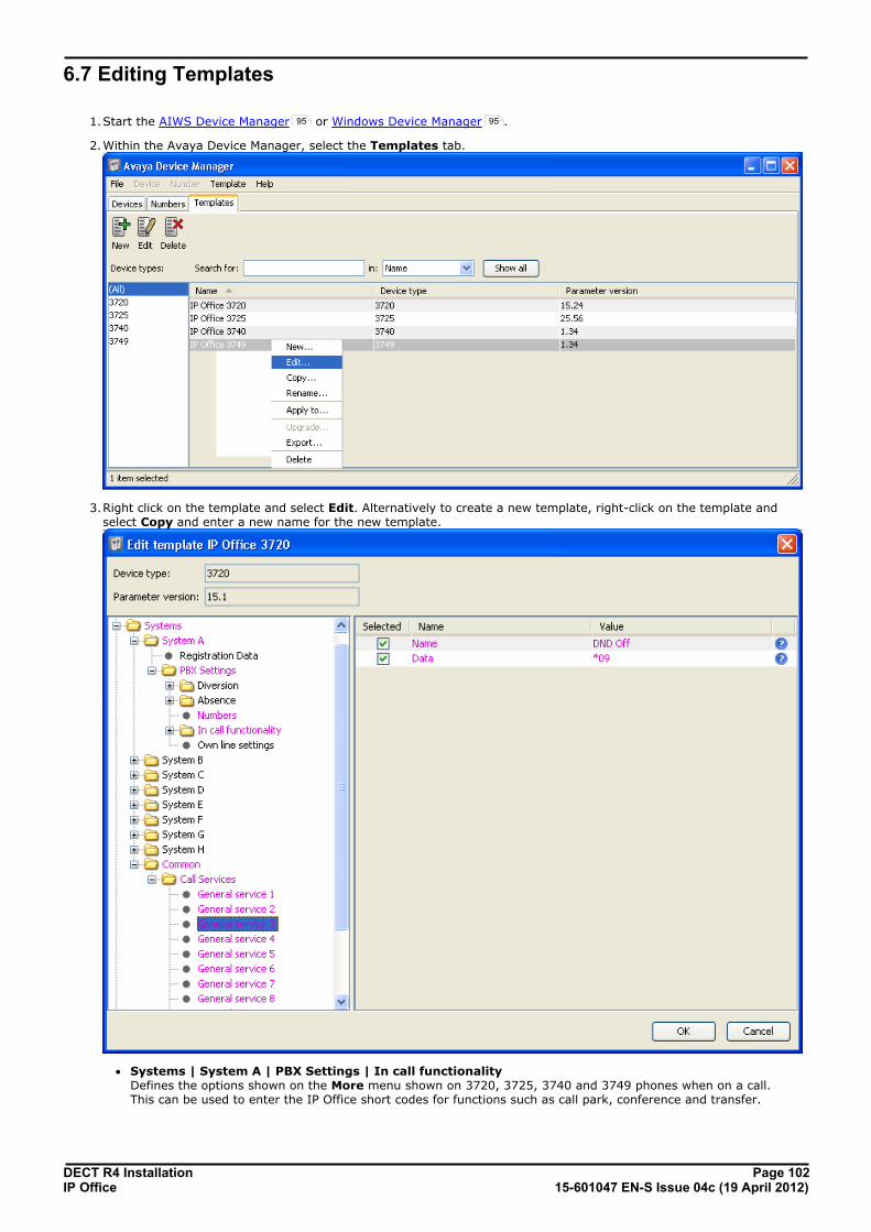
DECT R4 Installation Page 10215-601047 EN-S Issue 04c (19 April 2012)IP Office
6.7 Editing Templates
1.Start the AIWS Device Manager or Windows Device Manager .
2.Within the Avaya Device Manager, select the Templates tab.
3.Right click on the template and select Edit. Alternatively to create a new template, right-click on the template andselect Copy and enter a new name for the new template.
· Systems | System A | PBX Settings | In call functionality Defines the options shown on the More menu shown on 3720, 3725, 3740 and 3749 phones when on a call.This can be used to enter the IP Office short codes for functions such as call park, conference and transfer.
95 95
DECT R4 Installation Page 10315-601047 EN-S Issue 04c (19 April 2012)IP Office
Device Management: Editing Templates
· Systems | Common | Call Services Defines the options shown on the 3720, 3725, 3740 and 3749 phone Call services menu. This can be used toenter the IP Office short codes for functions such as call pickup, DND on/off.
4.This items shown in pink indicate areas of the template that contains settings selected to be applied to the devicewhen the template is uploaded to the device. Items shown in blue have been changed during this editing session.
· Black: Normal
· Dark Blue: Parameter has been edited during the current session.
· Purple: The parameter is enabled in the template.
· Red: Value not valid.
· Turqoise: The value differs from the default value
5.Each item within the template consists of 3 parts:
· Selected - If selected, the template value will be applied to devices to which the template is uploaded.
· Name - The non-editable name for the template item.
· Value - The value for the template item. This may be a drop-down list from which selection can be made.
6. Click OK.

DECT R4 Installation Page 10415-601047 EN-S Issue 04c (19 April 2012)IP Office
6.8 Upgrading Phone SoftwareDECT R4 is supported on a range of Avaya systems. However, for IP Office operation, only software specificallydocumented as having been tested and supported with IP Office should be used. Details of supported software for anyparticular IP Office release is included in IP Office Technical Bulletin for that release.
1.Start the AIWS Device Manager or Windows Device Manager .
2.Within the Avaya Device Manager, select the Devices tab.
3.The current software version of each phone is shown. Compare this to the software versions available, shown bythe version set as part of the .pkg file name included with the DECT R4 software .
4.In the device manager, select the phones that you want to upgrade.
5.Click Upgrade Software. The menu shown will depend on whether you are using the AIWS for an over the airupgrade or WinPDM for an in charger upgrade.
95 95
34
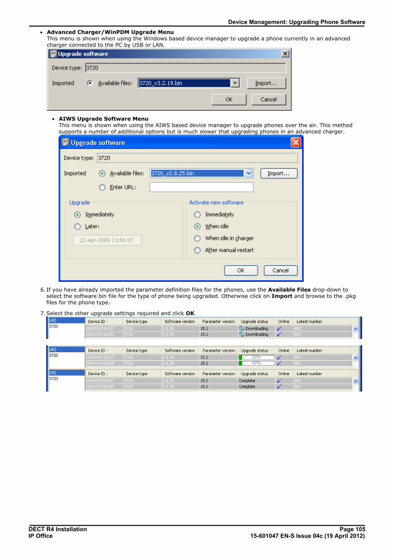
DECT R4 Installation Page 10515-601047 EN-S Issue 04c (19 April 2012)IP Office
Device Management: Upgrading Phone Software
· Advanced Charger/WinPDM Upgrade Menu This menu is shown when using the Windows based device manager to upgrade a phone currently in an advancedcharger connected to the PC by USB or LAN.
· AIWS Upgrade Software Menu This menu is shown when using the AIWS based device manager to upgrade phones over the air. This methodsupports a number of additional options but is much slower that upgrading phones in an advanced charger.
6.If you have already imported the parameter definition files for the phones, use the Available Files drop-down toselect the software bin file for the type of phone being upgraded. Otherwise click on Import and browse to the .pkgfiles for the phone type.
7.Select the other upgrade settings required and click OK.

DECT R4 Installation Page 10615-601047 EN-S Issue 04c (19 April 2012)IP Office
DECT R4 Installation Page 10715-601047 EN-S Issue 04c (19 April 2012)IP Office
AIWS Installation
Chapter 7.
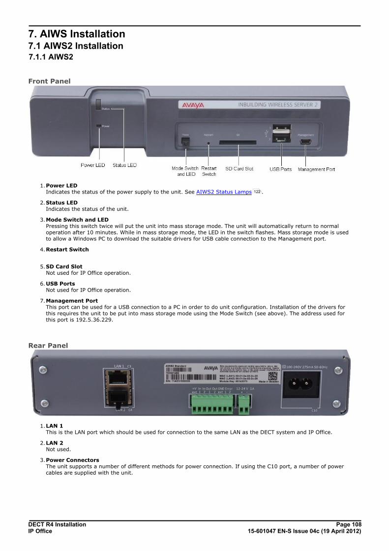
DECT R4 Installation Page 10815-601047 EN-S Issue 04c (19 April 2012)IP Office
7. AIWS Installation7.1 AIWS2 Installation7.1.1 AIWS2
Front Panel
1.Power LED Indicates the status of the power supply to the unit. See AIWS2 Status Lamps .
2.Status LED Indicates the status of the unit.
3.Mode Switch and LED Pressing this switch twice will put the unit into mass storage mode. The unit will automatically return to normaloperation after 10 minutes. While in mass storage mode, the LED in the switch flashes. Mass storage mode is usedto allow a Windows PC to download the suitable drivers for USB cable connection to the Management port.
4.Restart Switch
5.SD Card Slot Not used for IP Office operation.
6.USB Ports Not used for IP Office operation.
7.Management Port This port can be used for a USB connection to a PC in order to do unit configuration. Installation of the drivers forthis requires the unit to be put into mass storage mode using the Mode Switch (see above). The address used forthis port is 192.5.36.229.
Rear Panel
1.LAN 1 This is the LAN port which should be used for connection to the same LAN as the DECT system and IP Office.
2.LAN 2 Not used.
3.Power Connectors The unit supports a number of different methods for power connection. If using the C10 port, a number of powercables are supplied with the unit.
122

DECT R4 Installation Page 10915-601047 EN-S Issue 04c (19 April 2012)IP Office
AIWS Installation: AIWS2 Installation
7.1.2 Browse to the AIWS2By default the AIWS2 will obtain an IP address for it LAN 1 port using DHCP if possible. Using the unit's LAN 1 MACaddress, printed on the back of the unit,
Network Connection1.Connect the AIWS2 unit to the LAN using the LAN 1 port on the rear of the unit.
2.Connect the appropriate power cable to the unit and switch on the power supply.
3.The Status LED should change to a fast flashing blue while the unit is starting up.
4.When the starting up indication stops, you can attempt to browse to the unit.
5.Enter the IP address of the AIWS into the browser address field.
· Alternatively enter http://elise-XXXXXXXX as the address, where XXXXXXXX is the module key numberprinted on the back of the unit. Leading zeros can be omitted.
6.If a security certificate warning appears, select to continue.
7.Enter a user name and password. The default values are admin and changeme.
8. If this is the first time the AIWS2 has been started, the setup wizard is displayed. Otherwise the AIWS menu isshown.
USB Management ConnectionThe AIWS2 supports connection and administration via a USB cable connected to the Management port on the front ofthe unit. This requires the installation of a device driver that can be obtained from the unit by putting it into its MassStorage mode. Full details for installation and use are provided in the documentation provided with the unit.

DECT R4 Installation Page 11015-601047 EN-S Issue 04c (19 April 2012)IP Office
7.1.3 Run the Setup WizardThe first time the AIWS is accessed it runs he setup wizard.
1.Access the AIWS using your browser.
2.If the unit is defaulted, the setup wizard is run automatically. If the unit already has configuration settings, thenfrom the menu displayed select Setup Wizard.
3.Click Next. Enter the network address settings for the AIWS unit.
· Set the network parameters mode to Manually.
· Host Name Enter a name to help identify the AIWS on the network.
· IP Address/Subnet Mask Enter the static IP address details that the AIWS should use.
· Set the remaining details to match those being used by other devices on the network.

DECT R4 Installation Page 11115-601047 EN-S Issue 04c (19 April 2012)IP Office
AIWS Installation: AIWS2 Installation
4.Click Next. Enter the license number supplied with the AIWS unit.
5.Click Next. Enter the IP address of the master base station.
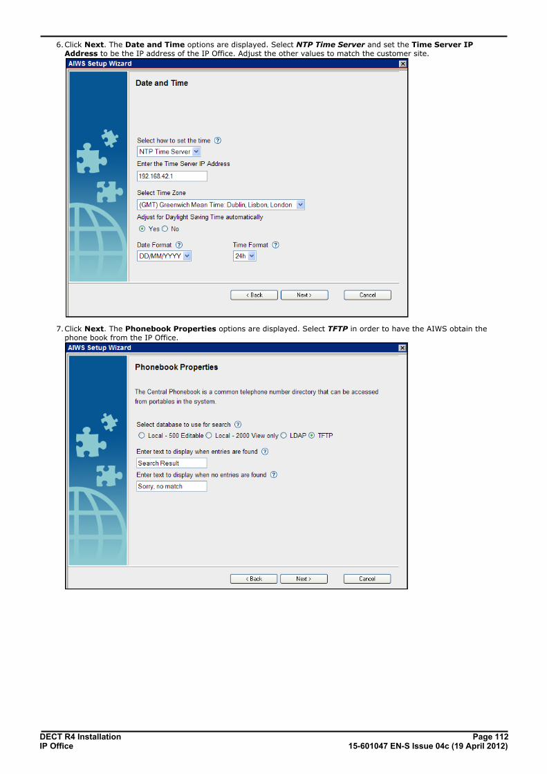
DECT R4 Installation Page 11215-601047 EN-S Issue 04c (19 April 2012)IP Office
6.Click Next. The Date and Time options are displayed. Select NTP Time Server and set the Time Server IPAddress to be the IP address of the IP Office. Adjust the other values to match the customer site.
7.Click Next. The Phonebook Properties options are displayed. Select TFTP in order to have the AIWS obtain thephone book from the IP Office.
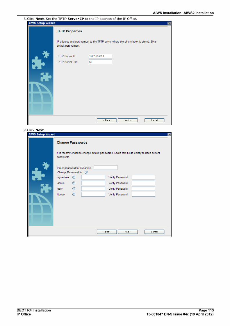
DECT R4 Installation Page 11315-601047 EN-S Issue 04c (19 April 2012)IP Office
AIWS Installation: AIWS2 Installation
8.Click Next. Set the TFTP Server IP to the IP address of the IP Office.
9.Click Next.

DECT R4 Installation Page 11415-601047 EN-S Issue 04c (19 April 2012)IP Office
10.Click Next.
11.Click Finish.

DECT R4 Installation Page 11515-601047 EN-S Issue 04c (19 April 2012)IP Office
AIWS Installation: AIWS2 Installation
12.Click Restart Now.
13.Close the browser access session. Start a new session using the new IP address.

DECT R4 Installation Page 11615-601047 EN-S Issue 04c (19 April 2012)IP Office
7.1.4 Enable Base Station/AIWS ConnectionThe IP address of the AIWS needs to be entered into the configuration of the base stations.
Master Only1.In the left-hand panel, select UNITE. Select the Device Management tab.
2.For the Unite IP Address, enter the IP address that will be assigned to the AIWS unit when installed in the DECTsystem.
3.Click OK.
4. In the left-hand panel select General. Select the Admin tab. Enable Show Advanced Options and refresh.
5.In the left-hand panel select Phonebook and disable the phonebook option.
6.Click OK and reset the master base station.
Master and Slave1.In the left-hand panel, select UNITE. Select the Status Log tab.
2.For the Unite IP Address, enter the IP address that will be assigned to the AIWS unit when installed in the DECTsystem.
3.For the Unite Resource Identity enter a unique name to be associated with the base station.
4.Click OK.
5.Select the SMS tab. Again enter the IP address that will be assigned to the AIWS unit when installed in the DECTsystem.
6.Click OK.

DECT R4 Installation Page 11715-601047 EN-S Issue 04c (19 April 2012)IP Office
AIWS Installation: AIWS2 Installation
7.1.5 Upgrade the AIWS FirmwareThe AIWS will have been supplied with a default set of firmware. This must be upgraded to the firmware provided with theIP Office application software. Only the firmware supplied with the IP Office application software or indicated in IP OfficeTechnical Bulletin should be used with AIWS units on IP Office DECT R4 systems.
· Important: This process can take up to 40 minutes.
1.Using a browser login to the unit.
2.Click on Configuration.
3.Note the software version. Check whether this already matches the firmware detailed as supported by the level ofsoftware on the IP Office system.
4.In the browser address bar, change the /config/start.php part of the address to /system.
5.Click on Software.

DECT R4 Installation Page 11815-601047 EN-S Issue 04c (19 April 2012)IP Office
6.Click Install Image.
7.Click Backup parameters.
8.The browser will show it dialog for downloading a file called aiws-backup from the AIWS unit. Select the option tosave the file and select a location to which it should be saved. Note the location as the file needs to be reloadedafter the firmware upgrade.
9.Click Start installation.
10.After a short delay, the AIWS should prompt you for the location of the firmware file for the upload.

DECT R4 Installation Page 11915-601047 EN-S Issue 04c (19 April 2012)IP Office
AIWS Installation: AIWS2 Installation
11.Click on Browse. Locate the AIWS folder in the software set previously unpacked. Select the .img file.
12.Click Write to flash.
13.Now go make a cup of tea and maybe read a book - It is not fast and must be allowed to complete.
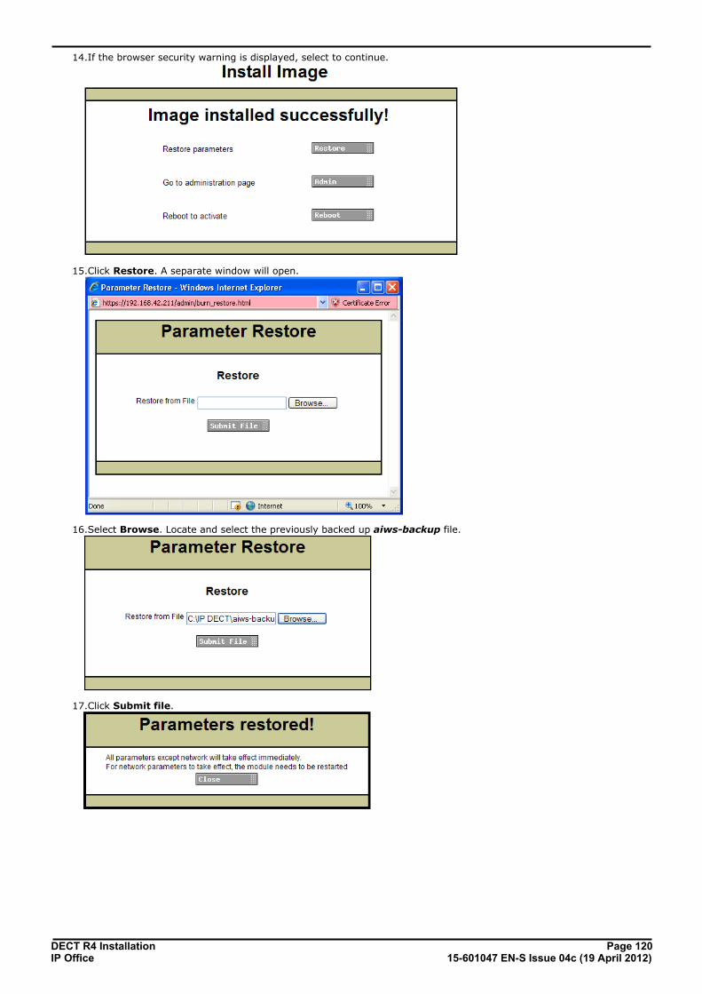
DECT R4 Installation Page 12015-601047 EN-S Issue 04c (19 April 2012)IP Office
14.If the browser security warning is displayed, select to continue.
15.Click Restore. A separate window will open.
16.Select Browse. Locate and select the previously backed up aiws-backup file.
17.Click Submit file.

DECT R4 Installation Page 12115-601047 EN-S Issue 04c (19 April 2012)IP Office
AIWS Installation: AIWS2 Installation
18. Click Close.
19.Select Reboot.

DECT R4 Installation Page 12215-601047 EN-S Issue 04c (19 April 2012)IP Office
7.1.6 AIWS2 Status Lamps
Status LED
Colour State Description
Blue On OK. AIWS operational.
Fast Flash Starting up or shutting down.
Red Fast flash Error or fault.
Slow flash Warning
Yellow Double blink Waiting for automatic startup.
Power LED
Colour State Description
Blue On Power OK.
Red Fast flash Shutting down due to low voltage.
Slow flash Low voltage.
Mode LEDThis LED is incorporated into the Mode button on the front of the unit.
Colour State Description
Blue Slow flash Mass storage mode.
7.2 AIWS1 InstallationThe AIWS (Avaya In-Built Wireless Server) unit allows SMS messaging between handsets. It also allows wireless softwareupgrades and configuration of the handsets. Without an AIWS, handsets can only be upgraded and configured when in anadvanced charger.
For IP Office Release 5 this unit also provides directory integration between the IP Office and the DECT R4 system.
For IP Office Release 6 and higher, directory integration is done by the master base station without requiring an AIWS.However an AIWS is still required for both functions if SMS is needed.
The unit is managed via web browser and requires a fixed IP address.
The AIWS installation consists of the following stages:
1.Remove the AIWS Cover.
2.Connect the RTC Battery.
3.Connect the LAN and Power Cables.
4.Browse to the AIWS.
5.Run the Setup Wizard.
6.Enable Base Station/AIWS Connections.
7.Upgrade the AIWS Firmware.
8.Switch off the AIWS.
9.Wall Mount the AIWS.
10.Replace the AIWS Cover.

DECT R4 Installation Page 12315-601047 EN-S Issue 04c (19 April 2012)IP Office
AIWS Installation: AIWS1 Installation
Pre-Requisites· o Master base station installed and connected to the network.
· o IP Office connected to the network.
· o Phones subscribed.
Parts Required· o AIWS Unit which includes:
· o AIWS Unit
· o AIWS Power Supply unit and selection of IEC60320 C7 power leads (CEE7/16 (Europlug), BS1363, NEMA1-15 and AS/NZS 3112).
· o 1.2 metre (4 foot) LAN cable.If this is replaced with a longer cable the replacement should be a CAT5 Ethernet LAN cable.
· o AIWS License sheet.
· o 3 x 3.5mm Screws and suitable wall plugs for the wall mounting of the AIWS.
· o LAN Socket
· o Mains power outlet socket.
Information· o IP Address for the AIWS
· o Other standard network settings (Default Gateway, DNS, WINS)
· o AIWS License Key (this should have been supplied with the AIWS)
· o IP Address of the DECT Master base station.
· o IP Address of the IP Office
· o Preferred time settings (date format, time format)
· o Wall mounting location selected for the AIWS
· o Access information (name and password) for configuring the base stations.
Tools· o Programming PC with DECT R4 software.
· o Web browser.
· o Pliers and sharp knife for removal of plastic cable cut-outs from AIWS case.
· o Drill and drill bits suitable for the selected wall mounting position of the AIWS.
· o Screwdrivers for use with the screws selected for AIWS wall mounting.

DECT R4 Installation Page 12415-601047 EN-S Issue 04c (19 April 2012)IP Office
7.2.1 Removing the AIWS CoverThe AIWS cover can be removed without using any tools.
1.On the base of the unit (opposite the rounded end) are two depressible clips. Depress these whilst lifting the cover.
2.It should be possible to lift the cover off the unit.
3.With the cover removed, familiarize yourself with the various features labeled above. These will be referred toduring other parts of the installation process.
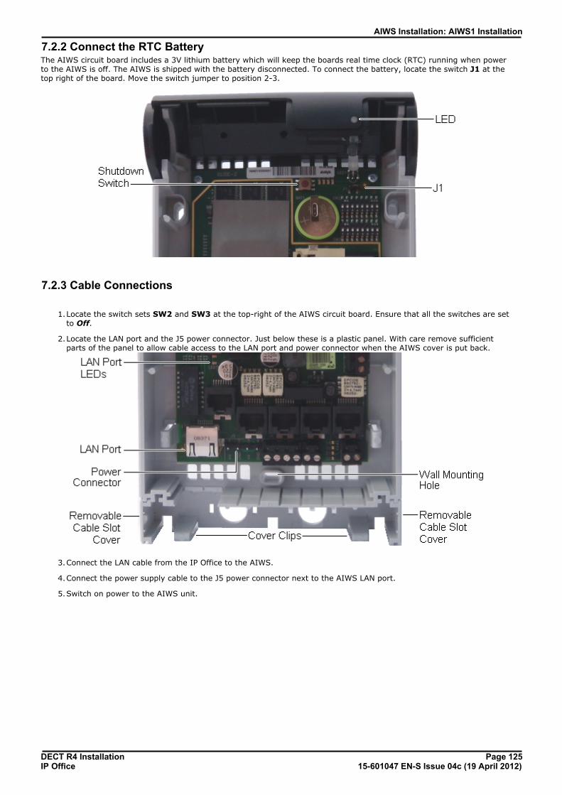
DECT R4 Installation Page 12515-601047 EN-S Issue 04c (19 April 2012)IP Office
AIWS Installation: AIWS1 Installation
7.2.2 Connect the RTC BatteryThe AIWS circuit board includes a 3V lithium battery which will keep the boards real time clock (RTC) running when powerto the AIWS is off. The AIWS is shipped with the battery disconnected. To connect the battery, locate the switch J1 at thetop right of the board. Move the switch jumper to position 2-3.
7.2.3 Cable Connections
1.Locate the switch sets SW2 and SW3 at the top-right of the AIWS circuit board. Ensure that all the switches are setto Off.
2.Locate the LAN port and the J5 power connector. Just below these is a plastic panel. With care remove sufficientparts of the panel to allow cable access to the LAN port and power connector when the AIWS cover is put back.
3.Connect the LAN cable from the IP Office to the AIWS.
4.Connect the power supply cable to the J5 power connector next to the AIWS LAN port.
5.Switch on power to the AIWS unit.
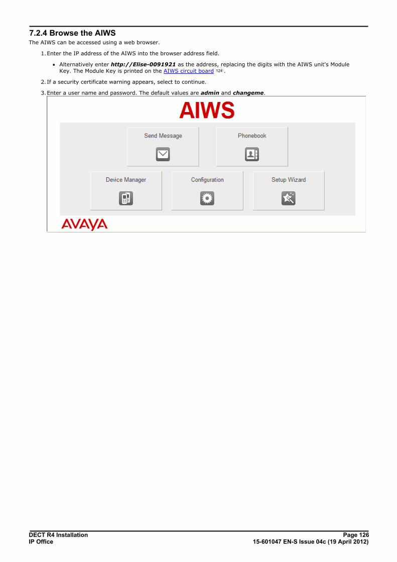
DECT R4 Installation Page 12615-601047 EN-S Issue 04c (19 April 2012)IP Office
7.2.4 Browse the AIWSThe AIWS can be accessed using a web browser.
1.Enter the IP address of the AIWS into the browser address field.
· Alternatively enter http://Elise-0091921 as the address, replacing the digits with the AIWS unit's ModuleKey. The Module Key is printed on the AIWS circuit board .
2.If a security certificate warning appears, select to continue.
3.Enter a user name and password. The default values are admin and changeme.
124
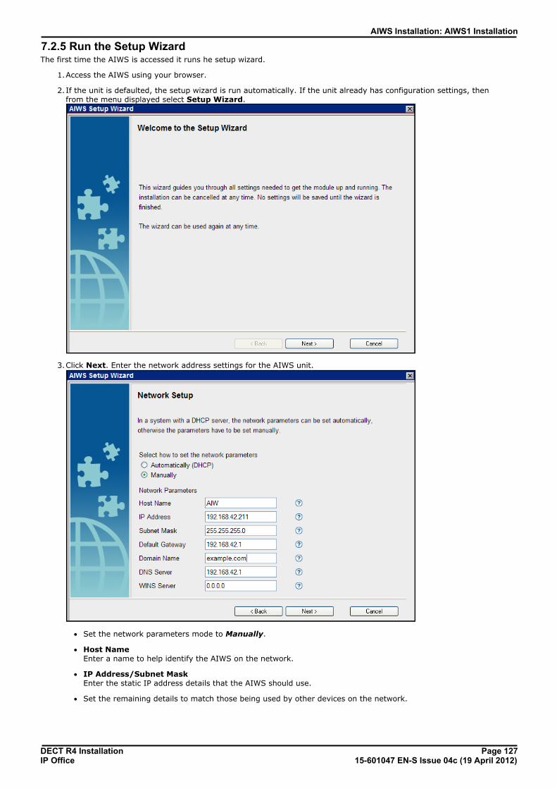
DECT R4 Installation Page 12715-601047 EN-S Issue 04c (19 April 2012)IP Office
AIWS Installation: AIWS1 Installation
7.2.5 Run the Setup WizardThe first time the AIWS is accessed it runs he setup wizard.
1.Access the AIWS using your browser.
2.If the unit is defaulted, the setup wizard is run automatically. If the unit already has configuration settings, thenfrom the menu displayed select Setup Wizard.
3.Click Next. Enter the network address settings for the AIWS unit.
· Set the network parameters mode to Manually.
· Host Name Enter a name to help identify the AIWS on the network.
· IP Address/Subnet Mask Enter the static IP address details that the AIWS should use.
· Set the remaining details to match those being used by other devices on the network.

DECT R4 Installation Page 12815-601047 EN-S Issue 04c (19 April 2012)IP Office
4.Click Next. Enter the license number supplied with the AIWS unit.
5.Click Next. Enter the IP address of the master base station.

DECT R4 Installation Page 12915-601047 EN-S Issue 04c (19 April 2012)IP Office
AIWS Installation: AIWS1 Installation
6.Click Next. The Date and Time options are displayed. Select NTP Time Server and set the Time Server IPAddress to be the IP address of the IP Office. Adjust the other values to match the customer site.
7.Click Next. The Phonebook Properties options are displayed. Select TFTP in order to have the AIWS obtain thephone book from the IP Office.

DECT R4 Installation Page 13015-601047 EN-S Issue 04c (19 April 2012)IP Office
8.Click Next. Set the TFTP Server IP to the IP address of the IP Office.
9.Click Next.

DECT R4 Installation Page 13115-601047 EN-S Issue 04c (19 April 2012)IP Office
AIWS Installation: AIWS1 Installation
10.Click Next.
11.Click Finish.

DECT R4 Installation Page 13215-601047 EN-S Issue 04c (19 April 2012)IP Office
12.Click Restart Now.
13.Close the browser access session. Start a new session using the new IP address.

DECT R4 Installation Page 13315-601047 EN-S Issue 04c (19 April 2012)IP Office
AIWS Installation: AIWS1 Installation
7.2.6 Enable Base Station/AIWS ConnectionThe IP address of the AIWS needs to be entered into the configuration of the base stations.
Master Only1.In the left-hand panel, select UNITE. Select the Device Management tab.
2.For the Unite IP Address, enter the IP address that will be assigned to the AIWS unit when installed in the DECTsystem.
3.Click OK.
4. In the left-hand panel select General. Select the Admin tab. Enable Show Advanced Options and refresh.
5.In the left-hand panel select Phonebook and disable the phonebook option.
6.Click OK and reset the master base station.
Master and Slave1.In the left-hand panel, select UNITE. Select the Status Log tab.
2.For the Unite IP Address, enter the IP address that will be assigned to the AIWS unit when installed in the DECTsystem.
3.For the Unite Resource Identity enter a unique name to be associated with the base station.
4.Click OK.
5.Select the SMS tab. Again enter the IP address that will be assigned to the AIWS unit when installed in the DECTsystem.
6.Click OK.

DECT R4 Installation Page 13415-601047 EN-S Issue 04c (19 April 2012)IP Office
7.2.7 Upgrade the AIWS FirmwareThe AIWS will have been supplied with a default set of firmware. This must be upgraded to the firmware provided with theIP Office application software. Only the firmware supplied with the IP Office application software or indicated in IP OfficeTechnical Bulletin should be used with AIWS units on IP Office DECT R4 systems.
· Important: This process can take up to 40 minutes.
1.Using a browser login to the unit.
2.Click on Configuration.
3.Note the software version. Check whether this already matches the firmware detailed as supported by the level ofsoftware on the IP Office system.
4.In the browser address bar, change the /config/start.php part of the address to /system.
5.Click on Software.

DECT R4 Installation Page 13515-601047 EN-S Issue 04c (19 April 2012)IP Office
AIWS Installation: AIWS1 Installation
6.Click Install Image.
7.Click Backup parameters.
8.The browser will show it dialog for downloading a file called aiws-backup from the AIWS unit. Select the option tosave the file and select a location to which it should be saved. Note the location as the file needs to be reloadedafter the firmware upgrade.
9.Click Start installation.
10.After a short delay, the AIWS should prompt you for the location of the firmware file for the upload.

DECT R4 Installation Page 13615-601047 EN-S Issue 04c (19 April 2012)IP Office
11.Click on Browse. Locate the AIWS folder in the software set previously unpacked. Select the .img file.
12.Click Write to flash.
13.Now go make a cup of tea and maybe read a book - It is not fast and must be allowed to complete.
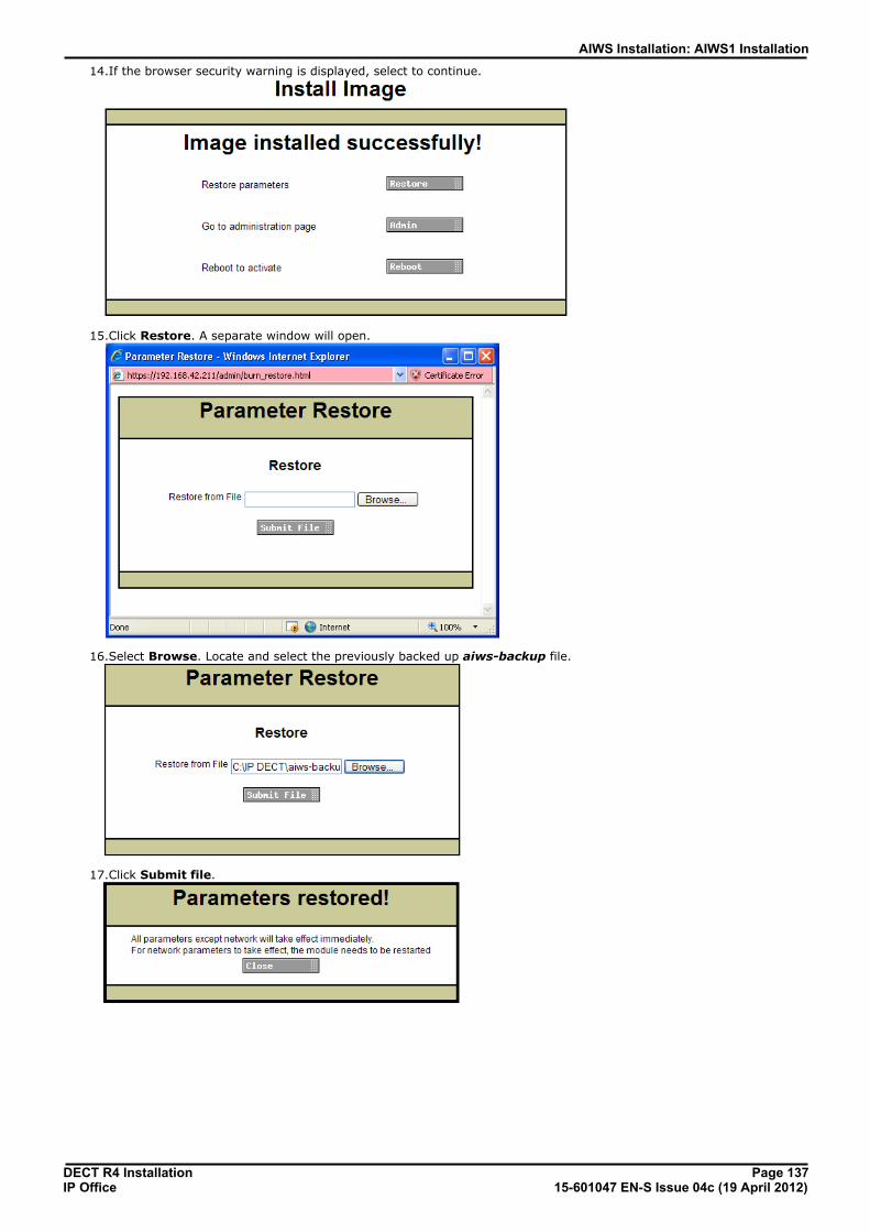
DECT R4 Installation Page 13715-601047 EN-S Issue 04c (19 April 2012)IP Office
AIWS Installation: AIWS1 Installation
14.If the browser security warning is displayed, select to continue.
15.Click Restore. A separate window will open.
16.Select Browse. Locate and select the previously backed up aiws-backup file.
17.Click Submit file.

DECT R4 Installation Page 13815-601047 EN-S Issue 04c (19 April 2012)IP Office
18. Click Close.
19.Select Reboot.
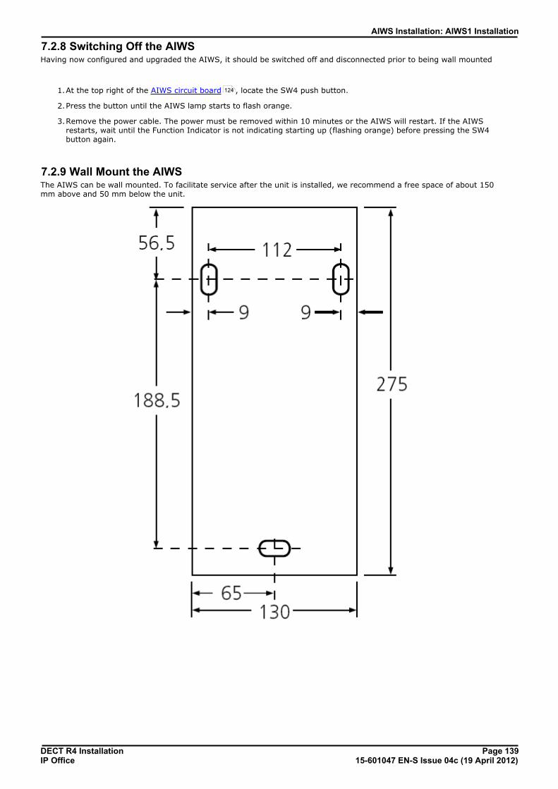
DECT R4 Installation Page 13915-601047 EN-S Issue 04c (19 April 2012)IP Office
AIWS Installation: AIWS1 Installation
7.2.8 Switching Off the AIWSHaving now configured and upgraded the AIWS, it should be switched off and disconnected prior to being wall mounted
1.At the top right of the AIWS circuit board , locate the SW4 push button.
2.Press the button until the AIWS lamp starts to flash orange.
3.Remove the power cable. The power must be removed within 10 minutes or the AIWS will restart. If the AIWSrestarts, wait until the Function Indicator is not indicating starting up (flashing orange) before pressing the SW4button again.
7.2.9 Wall Mount the AIWSThe AIWS can be wall mounted. To facilitate service after the unit is installed, we recommend a free space of about 150mm above and 50 mm below the unit.
124
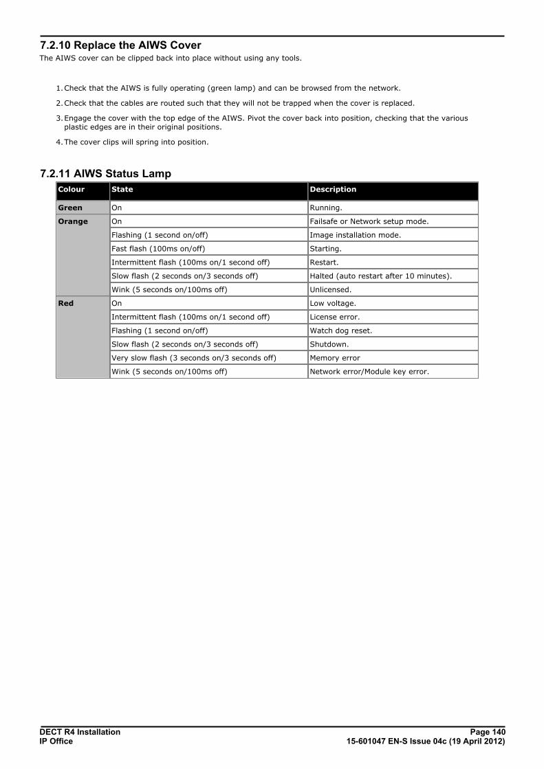
DECT R4 Installation Page 14015-601047 EN-S Issue 04c (19 April 2012)IP Office
7.2.10 Replace the AIWS CoverThe AIWS cover can be clipped back into place without using any tools.
1.Check that the AIWS is fully operating (green lamp) and can be browsed from the network.
2.Check that the cables are routed such that they will not be trapped when the cover is replaced.
3.Engage the cover with the top edge of the AIWS. Pivot the cover back into position, checking that the variousplastic edges are in their original positions.
4.The cover clips will spring into position.
7.2.11 AIWS Status Lamp
Colour State Description
Green On Running.
Orange On Failsafe or Network setup mode.
Flashing (1 second on/off) Image installation mode.
Fast flash (100ms on/off) Starting.
Intermittent flash (100ms on/1 second off) Restart.
Slow flash (2 seconds on/3 seconds off) Halted (auto restart after 10 minutes).
Wink (5 seconds on/100ms off) Unlicensed.
Red On Low voltage.
Intermittent flash (100ms on/1 second off) License error.
Flashing (1 second on/off) Watch dog reset.
Slow flash (2 seconds on/3 seconds off) Shutdown.
Very slow flash (3 seconds on/3 seconds off) Memory error
Wink (5 seconds on/100ms off) Network error/Module key error.

DECT R4 Installation Page 14115-601047 EN-S Issue 04c (19 April 2012)IP Office
AIWS Installation: AIWS1 Installation
7.2.12 Image Installation ModeThis is the maintenance process to put an AIWS into Image Installation mode. This is used to upload a .img file to theAIWS1 unit.
1. Remove the AIWS cover .
2. To set the AIWS to Image Installation mode:
a. Looking at the AIWS without the cover, the status LED should be towards the upper right corner
b. Beneath it there should be two rows of small switches, to the right of the round battery
c. The bottom one is of interest, as a way of being sure there should be a mark on the board right next to itsaying SW3.
d. All the switches should be marked with numbers in range 1 to 8, there should also be a mark ON.
e. Set only the switch labeled 4 to ON, the rest OFF.
3. From the browser make a reboot of the AIWS
a. If unable, there is another way: press the small button above and a bit to the left of the round battery on theAIWS circuit board
b. The press does not have to be long, a short one will do
c. There is a 10 minute waiting time when doing so, in addition to the actual shutdown and startup of the AIWS
d. The reboot from the browser does not have this waiting time, so it is preferred.
4. Access the AIWS through the web browser. Be sure to not type https in the address bar: in image installation modeit only works with http
5. Select the image file and upload it
6. Set the AIWS back to normal mode
a. Set the switch labeled 4 back to OFF like all the rest
7. Reboot the AIWS, preferably from the browser again.
8. You must reconfigure the AIWS settings. Although the IP address should have not been changed, if having troubleaccessing it try:
a. Setting the AIWS in network mode by turning the switch labeled 1 to ON
b. Reboot the AIWS
c. The status LED should be steady orange (not blinking at all)
d. Access the AIWS by the reserved IP address 192.5.36.229.
e. Enter the desired IP settings
f. Set the AIWS into normal mode by turning switch 1 back to OFF.
g. Reboot the AIWS
h. Access the AIWS using the newly entered LAN settings.
124


DECT R4 Installation Page 14315-601047 EN-S Issue 04c (19 April 2012)IP Office
Miscellaneous
Chapter 8.

DECT R4 Installation Page 14415-601047 EN-S Issue 04c (19 April 2012)IP Office
8. Miscellaneous8.1 Reset /Restart SwitchThe base stations (all types), IP DECT Gateway and AIWS2 all include a reset switch. To press it requires a fine point. Howlong the switch is depressed affects the type of reset.
Action Duration Effect
Short press Less than 1 second Restart
Medium press Approximately 3 seconds Restart in TFTP mode. This mode is intended for development only.
Long press Approximately 10 seconds Factory reset. All configuration parameters will be set to default values.
8.2 Base Station Status Lamps
IPBS2 Base StationsIPBS2 base stations have one LED to indicate status.
LED Description
Blue On Idle, no calls in progress.
Blue Fast Flash Starting up or searching for air synchronization.
Blue On - Regular Blink Calls in progress.
Blue On - Red Blink Maximum calls in progress.
Blue Slow Flash Firmware download in progress.
Yellow Fast Flash IPBS2 is in mini firmware mode.
Yellow On TFTP Mode (not used).
Red Fast Flash No Ethernet connection.
Red On Hardware error.
Blue On - Yellow Blink The IPBS2 is in deployment mode and has air synchronization.
Red On - Yellow Blink The IPBS2 is in deployment mode and has no air synchronization.
Blue Slow Flash/YellowFlash
The IPBS2 is in deployment mode and does not have adequate air synchronization.
Green Reset button depressed.
IPBS1 Base StationsEach IPBS1 base station has two LED lamps.
LED Color Description
LED 2 - Activity Off Idle, no calls in progress.
Green Calls in progress.
Green Flashing Maximum calls in progress.
Amber* Air synchronization insufficient and calls in progress.
Amber Flashing* Air synchronization insufficient and no calls in progress.
Amber Slow Flashing* Air synchronization insufficient and maximum calls in progress.
Red Flashing No air synchronization. Searching for synchronization signal.

DECT R4 Installation Page 14515-601047 EN-S Issue 04c (19 April 2012)IP Office
Miscellaneous: Base Station Status Lamps
Red Fast Flashing Download of RFP software in progress.
LED 1 - Status
This is the lower LEDon the bottom edgeof the base station.
Green Operational
Flashing Amber Firmware download in progress.
Amber Fast Flash TFTP Mode (not used).
Alternating Red/Green No Ethernet connection.
Digital Base StationDigital base stations have two LED lamps.
LED Color Description
LED 2 - Activity Off Idle, no calls in progress.
Green Calls in progress.
Green Flashing Maximum calls in progress.
Amber Base station OK but not operational (self-test, no communicationwith IP DECT Gateway).
Amber Flashing Software download in progress.
LED 1 - Status
This is the lower LEDon the bottom edgeof the base station.
Green Operational
– –
– –

DECT R4 Installation Page 14615-601047 EN-S Issue 04c (19 April 2012)IP Office
8.3 IP DECT Gateway Status Lamps
IP DECT Gateway Status LampThis LED is located at the left-hand end of the front panel of the IP DECT Gateway.
LED Description
Off No power.
Green slow flash Reset switch pressed.
Green fast flash Firmware update in progress or config cleared after reset.
Green on OK.
Red on Error.
Amber on TFTP mode.
Base Station Port LampsEach base station port has a left-hand and right-hand LED. These are used as follows:
Left-hand LED Right-hand LED
LED Description LED Description
Off No link to base station. Off No calls in progress.
On Linked and base station operational. On Calls in progress.
Flashing Linked but base station not operational. Flashing Maximum calls in progress.
LAN Port LampsEach LAN port has a left-hand and right-hand LED. These are used as follows:
Left-hand LED Right-hand LED
LED Description LED Description
Off No link or Ethernet connection. Off No connection or 10Mbps connection.
On No network activity. On 100Mbps connection
Flashing Network activity. – –
144

DECT R4 Installation Page 14715-601047 EN-S Issue 04c (19 April 2012)IP Office
Miscellaneous: IP DECT Gateway Status Lamps
8.4 AIWS2 Status Lamps
Status LED
Colour State Description
Blue On OK. AIWS operational.
Fast Flash Starting up or shutting down.
Red Fast flash Error or fault.
Slow flash Warning
Yellow Double blink Waiting for automatic startup.
Power LED
Colour State Description
Blue On Power OK.
Red Fast flash Shutting down due to low voltage.
Slow flash Low voltage.
Mode LEDThis LED is incorporated into the Mode button on the front of the unit.
Colour State Description
Blue Slow flash Mass storage mode.

DECT R4 Installation Page 14815-601047 EN-S Issue 04c (19 April 2012)IP Office
8.5 AIWS1 Status LampColour State Description
Green On Running.
Orange On Failsafe or Network setup mode.
Flashing (1 second on/off) Image installation mode.
Fast flash (100ms on/off) Starting.
Intermittent flash (100ms on/1 second off) Restart.
Slow flash (2 seconds on/3 seconds off) Halted (auto restart after 10 minutes).
Wink (5 seconds on/100ms off) Unlicensed.
Red On Low voltage.
Intermittent flash (100ms on/1 second off) License error.
Flashing (1 second on/off) Watch dog reset.
Slow flash (2 seconds on/3 seconds off) Shutdown.
Very slow flash (3 seconds on/3 seconds off) Memory error
Wink (5 seconds on/100ms off) Network error/Module key error.

DECT R4 Installation Page 14915-601047 EN-S Issue 04c (19 April 2012)IP Office
Miscellaneous: AIWS1 Status Lamp


DECT R4 Installation Page 15115-601047 EN-S Issue 04c (19 April 2012)IP Office
Non-Provisioned Installation
Chapter 9.

DECT R4 Installation Page 15215-601047 EN-S Issue 04c (19 April 2012)IP Office
9. Non-Provisioned InstallationThis method of installation is used with pre-IP Office Release 7.0 systems and systems that include handsets that do notsupport IP Office provisioning.
· When to Use Non-Provisioned Installation The use of IP Office provisioned installation is recommended for all installations except those that containno 3720, 3725, 3740 or 3749 phones.
· It is assumed that you are familiar with installation and configuration of IP Office systems.
Information· Service user name and password for IP Office configuration access.
· Service user name and password for IP Office security settings access.
· IP Office IP address.
· Avaya IP Endpoint licenses
Parts Required· IP Office Release 7.0 software DVD or image of the IP Office Release 7.0 admin software.
Tools Required· Programming PC with IP Office Manager application installed. You must have rights on this PC to change its IP
address settings unless it is a DHCP client.
· Software for zip file extraction.
IP Base Station Installation Requirements
Parts Required· Base station
Includes:
· Base station.
· Two 3.5mm screws and two 6mm wall plugs suitable for wall mounting onto a solid wall (brick or similar).
· 1.2 metre (4 foot) LAN cable. If this is replaced with a longer cable the replacement should be a CAT5 EthernetLAN cable.
· If using Power over Ethernet:
· The base station supports Power over Ethernet, IEEE 802.3af, class 2.
· If not using Power over Ethernet:
· Base station power supply unit. Required if not using Power over Ethernet to power the base station. Note that the base station power supplyunits include an 8 metre (26 feet) cable from the PSU to the base station. Check that you have the correct typeof power supply unit for the locale.
· BSX-0013: Europe (except United Kingdom).
· BSX-0014: United Kingdom.
· BSX-0015: USA/Canada.
· BSX-0016: Australia.
· Mains power outlet socket.
· LAN Socket.
Information· DECT R4 SARI.
· Base Station IP Addresses.
· Detailed plans from the site survey indicating the intended base station locations, LAN sockets and if necessarypower supply outlets.
32
DECT R4 Installation Page 15315-601047 EN-S Issue 04c (19 April 2012)IP Office
Non-Provisioned Installation:
Tools· Programming PC with DECT R4 software.
· Web browser.
· Drill and drill bits suitable for the selected wall mounting position of the AIWS.
· Screwdrivers for use with the screws selected for AIWS wall mounting.
Phone Subscription Requirements
Information· Service user name and password for IP Office configuration.
· User names and extension numbers for the DECT phones.
· Phone IPEI numbers if using an pre-configured installation mode.
Tools· IP Office Manager.
· Device Manager The software installed on each handset may need to be upgraded to match that supplied with the DECT R4 software
. This is done using the Windows Device Manager software to upgrade phones via an advanced charger orusing AIWS Device Manager to upgrade phones over the air.
· Web browser (Internet Explorer or Firefox are supported).
34
95

DECT R4 Installation Page 15415-601047 EN-S Issue 04c (19 April 2012)IP Office
9.1 DECT SoftwareBefore beginning installation, in addition to having IP Office Manager installed, you need to unpack the DECT R4 softwareonto your programming PC.
DECT R4 is supported on a range of Avaya systems. However, for IP Office operation, only firmware specificallydocumented as having been tested and supported with IP Office should be used. Details of supported firmware will beincluded in IP Office Technical Bulletins and Technical Tips.
1.On the programming PC, create a folder with a name indicating its purpose, for example c:\IP_DECT_R4.
2.Within the IP Office Administrator Application software (ie. the software from which IP Office Manager is installed),locate the folder IPDECT.
3.The folder contains a file DECT R4.zip. This is the file containing software for DECT R4. The file IPDECT.zipcontains software for the previously supported IP DECT product and not for DECT R4.
4.Copy the DECT R4.zip file to the folder created on the programming PC.
5.Using WinZip or a similar tool, extract the contents of the zip file into the folder, maintaining the directory structureof the zip files.
6.The set of files should appear similar to the following.
7.Check the software levels as follows:
· Open the IP Base Station folder. There are separate sub-folders for IPBS1 and IPBS2 base stations. Openeach and note the software level shown as part of the .bin file filenames, there are separate files for the basestation boot file and firmware file. All the base station in the installed system should be run the same levels ofsoftware.
· Open the Handsets folder and note the software level shown as part of the .pkg file filenames. The handsetsin the system should be running this level of software or higher.
· Open the IP DECT Gateway folder and note the software level shown as part of the .bin filenames.

DECT R4 Installation Page 15515-601047 EN-S Issue 04c (19 April 2012)IP Office
Non-Provisioned Installation: DECT Software
9.2 Adding LicensesEach IP DECT extension requires an Avaya IP Endpoint license. This applies even if the handset subscribed to the IP DECTR4 system is not an Avaya phone.
Phones without a license will still be able to subscribe and register but will be limited to making emergency calls only (callsthat match an IP Office Dial Emergency short code). The associated user will be treated as if logged off. If a licensebecomes available, it will be assigned to any unlicensed DECT handsets first and then to any other unlicensed Avaya IPphone in the order that the phones registered.
· Avaya IP Endpoint Licenses Licenses are added to the IP Office configuration and are based on a serial number unique to the system.
· Phones can be licensed up to the 384 extension limit for all phone extensions of any type.
· For each IP500 VCM 32 or IP500 VCM 64 card installed in the system also enables 12 Avaya IP endpointswithout requiring licenses.
· For each IP400 VCM card installed in the system, each VCM channel supported by the card allows supportfor 3 Avaya IP phones.
· The VCM channels provided by IP500 Combination cards do not enable any Avaya IP endpoints.
· Licenses are normally automatically assigned to extensions in order of registration. However, existingextensions can be configured to reserve a license . This ensures that they do not become unlicensedwhen newly added extensions manage to register first following a system reboot.
9.2.1 Checking the Licensing NumberIP Office licenses are issued against a unique dongle serial number. For IP500 control units, the number is unique to thesmart card fitted to the control unit. For IP500v2 control units, the number is unique to the System SD card fitted to thesystem. For any licenses entered into the system configuration to be valid, they must be licenses issued against that serialnumber.
1.Using IP Office Manager, receive the configuration from the IP Office system.
2.Select System.
3.Select the System tab.
4.The feature key serial number is shown by the Dongle Serial Number field.
9.2.2 Adding Licenses1.Using IP Office Manager, receive the configuration from the IP Office system.
2.Select License.
3.The current licenses in the system configuration are displayed.
4.To add a license click on and select License.
5.Enter the license which you have been supplied and click OK.
6.The type of the license, Avaya IP endpoints, should be displayed but with its License Status set to Unknown. Ifthe License Type was not recognized, check that the key was entered correctly.
7.Save the configuration back to the IP Office system and then receive the configuration from the IP Office systemagain.
8.The License Status should now be Valid.
42

DECT R4 Installation Page 15615-601047 EN-S Issue 04c (19 April 2012)IP Office
9.2.3 Reserving LicensesLicenses are normally automatically assigned to extensions in order of registration. However existing extensions canreserve a license in order to ensure they do not become unlicensed when new extensions added to the system manage toregister first following a system reboot.
1.Using IP Office Manager, receive the configuration from the IP Office system.
2.Select Extension and then select the DECT extension.
3.Select the IP DECT tab. Note, the appearance of this menu will vary depending on whether you are doing aprovisioned or non-provisioned installation.
4.The Reserve Avaya IP endpoint license setting is used to reserve an existing license for the extension. Theoption is greyed out if the configuration does not have sufficient unreserved licenses remaining.
5.Repeat the process for any other extensions for which you want to reserve the license.
6.Save the configuration back to the IP Office system.

DECT R4 Installation Page 15715-601047 EN-S Issue 04c (19 April 2012)IP Office
Non-Provisioned Installation: Adding Licenses
9.3 IP DECT Line SetupAt this stage we will create an IP DECT line for traffic between the IP Office and the DECT R4 system. The line isconfigured with the IP address of the master base station. The IP Office configuration only requires and allows a single IPDECT line.
· Reboot Required Add or removing a line from the IP Office configuration requires the IP Office system to reboot. This will end all callsand services in progress.
1.Using IP Office Manager, receive the configuration from the IP Office system.
2.Click on Line. The list of existing lines is shown.
3.Click on the icon and select IP DECT Line. The settings for an IP DECT line are displayed. If the option is greyedout then the configuration already contains an IP DECT line.
4.On the Line tab there are no adjustable settings. Once the system is installed and operational, this tab will list theDECT extensions.
5.Select the VoIP tab. This table is used to set details of the master base station.
a.Set the Gateway IP Address to match the IP address that will be assigned to the master base station. TheMAC Address field is not used.
b.Leave the other fields at their default settings.
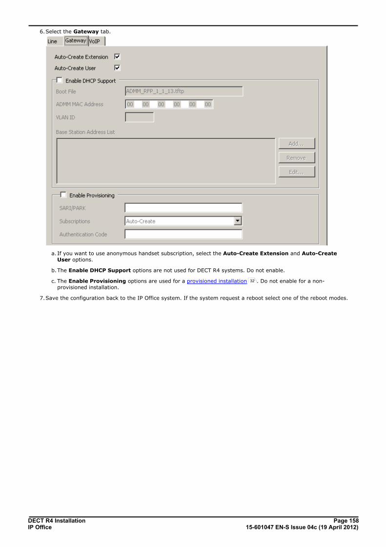
DECT R4 Installation Page 15815-601047 EN-S Issue 04c (19 April 2012)IP Office
6.Select the Gateway tab.
a. If you want to use anonymous handset subscription, select the Auto-Create Extension and Auto-CreateUser options.
b.The Enable DHCP Support options are not used for DECT R4 systems. Do not enable.
c. The Enable Provisioning options are used for a provisioned installation . Do not enable for a non-provisioned installation.
7.Save the configuration back to the IP Office system. If the system request a reboot select one of the reboot modes.
32
DECT R4 Installation Page 15915-601047 EN-S Issue 04c (19 April 2012)IP Office
Non-Provisioned Installation: IP DECT Line Setup
9.4 Master Base Station ConfigurationThe base station installation process consists of the following stages:
1.Default the base station.
2.Access the base station configuration.
3.Update the base station firmware.
4.Set the base station IP address.
5.Set the time source.
6.Set the QoS/ToS settings.
7.Enable status logging by the AIWS.
8.Set the base station as the master base station.
9.Select the PBX Switch mode.
10.Configure the IP trunk.
11.Enable the radio settings.
12.Enter the PARI code.
13.Enter the SARI/PARK code.
14.Configure Air Synch.
15.Configure IP Office Directory Integration.
16.Reset the base station.
17.Check the base station.
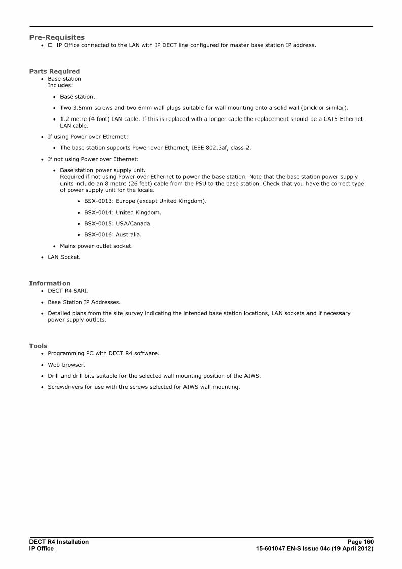
DECT R4 Installation Page 16015-601047 EN-S Issue 04c (19 April 2012)IP Office
Pre-Requisites· o IP Office connected to the LAN with IP DECT line configured for master base station IP address.
Parts Required· Base station
Includes:
· Base station.
· Two 3.5mm screws and two 6mm wall plugs suitable for wall mounting onto a solid wall (brick or similar).
· 1.2 metre (4 foot) LAN cable. If this is replaced with a longer cable the replacement should be a CAT5 EthernetLAN cable.
· If using Power over Ethernet:
· The base station supports Power over Ethernet, IEEE 802.3af, class 2.
· If not using Power over Ethernet:
· Base station power supply unit. Required if not using Power over Ethernet to power the base station. Note that the base station power supplyunits include an 8 metre (26 feet) cable from the PSU to the base station. Check that you have the correct typeof power supply unit for the locale.
· BSX-0013: Europe (except United Kingdom).
· BSX-0014: United Kingdom.
· BSX-0015: USA/Canada.
· BSX-0016: Australia.
· Mains power outlet socket.
· LAN Socket.
Information· DECT R4 SARI.
· Base Station IP Addresses.
· Detailed plans from the site survey indicating the intended base station locations, LAN sockets and if necessarypower supply outlets.
Tools· Programming PC with DECT R4 software.
· Web browser.
· Drill and drill bits suitable for the selected wall mounting position of the AIWS.
· Screwdrivers for use with the screws selected for AIWS wall mounting.

DECT R4 Installation Page 16115-601047 EN-S Issue 04c (19 April 2012)IP Office
Non-Provisioned Installation: Master Base Station Configuration
9.4.1 Default the Base StationThis process will default a base station or IP DECT Gateway, erasing its configuration. After the unit restarts it will defaultto the IP address 192.168.0.1/255.255.255.0.
1.With the unit not connected to anything else, connect the power supply and switch on.
2.Wait approximately 5 seconds.
3.Using a fine point, depress the unit's reset switch for at least 10 seconds.
4.Release the switch. The unit will restart.
5.After approximately 5 seconds the unit will default to the address 192.168.0.1.
Alternate MethodThe address an existing base station or IP DECT Gateway is using can be determined using the following process. It usesthe MAC address of the unit which is printed on a label on the back or bottom of the unit.
1.Open a Windows command window by selecting Start | Run and enter cmd.
2.Enter nbtstat -R. The PC should respond that is has purged and reloaded the NBT remote cache table.
3.For a base station enter nbtstat -a ipbs-xx-xx-xx when xx-xx-xx is replaced with the last 6 hexadecimal digits ofthe base stations MAC address. For a IP DECT Gateway, enter nbtstat -a ipbl-xx-xx-xx.
4.The results will show the IP address which it being used.
4.Use that address to access the base stations configuration and set it to a fixed address.

DECT R4 Installation Page 16215-601047 EN-S Issue 04c (19 April 2012)IP Office
9.4.2 Access the Base Station's Configuration1.Depending on whether DHCP is being used or not:
· If connected directly to the base station, change your programming PC's network address to 192.168.0.200with subnet mask 255.255.255.0. Connect the LAN cable from your PC to the base station.
· If both your PC and the base station are connected to a LAN network with DHCP server, ensure your PC is setto act as a DHCP client or has a fixed address that is valid on the network.
2.Start your web browser and enter the http:// or https:// followed by the IP address of the base station. The defaultIP address is 192.168.0.1. If a security certificate warning is displayed, select to continue to this website.
3.The base station should respond with its initial configuration menu.
4.Select System administration. A password entry dialog will be displayed. Enter the default user name (admin)and password (changeme).
5.The configuration menu for the base station is displayed.
6.Note the software levels shown in the Version screen. These will determine whether the base station software needsto be upgraded.

DECT R4 Installation Page 16315-601047 EN-S Issue 04c (19 April 2012)IP Office
Non-Provisioned Installation: Master Base Station Configuration
9.4.3 Update the Base Station FirmwareThe base station may need to be upgraded to the software supplied for use with IP Office administration software. Thatsoftware consists of two parts, a firmware file and a boot file. All base stations in a DECT system should use the samesoftware.
1.Browse into the base station's configuration and note the software levels shown by the Version line.
· Check that these match the versions supplied with the IP Office administration software. Ensure that you arechecking against the correct folder for an IPBS1 or IPBS2 base station. If they do not not match, then the basestation should be upgraded.
· If both software files need to be upgraded, the boot file should be upgraded first.
2.To upgrade the boot file, in the left-hand column select Update and then select the Boot tab. To upgrade the basestation file, select Update and then select the Firmware tab. The method for both files is similar, however ensureyou upgrade the boot file first if both need to be upgraded.
3.Click on the Choose File button and browse to the IP Base Station sub-folder of the IP DECT R4 software youpreviously extracted onto the programming PC.
4.Select the appropriate file for the upgrade you are performing, ie. the file with boot in the file name if doing a bootfile upgrade. Click OK.
5.Click on the Upload button.
6.The browser will show the progress of the upload and firmware upgrade. It will indicate when the process has beencompleted.

DECT R4 Installation Page 16415-601047 EN-S Issue 04c (19 April 2012)IP Office
7.Click on immediate reset.
8.Login in again. The General | Info tab should now list the new firmware.
9.If necessary, repeat the process for the firmware using the Update | Firmware menu.
10.For a IP DECT Gateway, if necessary also repeat the process for base station firmware for base stations that will beconnected to the IP DECT Gateway using the Update | RFPs menu.
Repeat the steps above for any other base stations that are also being installed. All the base stations should use the samefirmware.

DECT R4 Installation Page 16515-601047 EN-S Issue 04c (19 April 2012)IP Office
Non-Provisioned Installation: Master Base Station Configuration
9.4.4 Set the Base Station IP AddressBy default a base station defaults to 192.168.0.1. The process below can be used to change the DHCP mode and IPaddress of the base station.
1.Having browsed into the base station's configuration, in the left-hand column select LAN.
2.Select the IP tab.
a. Enter the required IP Address and Network Mask for the base station. The other settings are optional.
b.Click OK.
3.Select the DHCP tab.
a.Using the Mode drop-down, select Disabled.
b.Click OK.
4.The menu will prompt you with the message Reset Required. Do not click this or reset the base station at thisstage.
a.Select Reset and then select the Reset tab.
b.Click on OK.
c. Observing the base station, wait for the lower light to return to solid green.
5.Log in again using the new IP address.

DECT R4 Installation Page 16615-601047 EN-S Issue 04c (19 April 2012)IP Office
9.4.5 Set the Time SourceThe base station can obtain its time from the IP Office control unit.
1.In the left-hand column select General. Select the NTP tab.
2.In the Time Server field enter the IP address of the IP Office.
3.Click OK.

DECT R4 Installation Page 16715-601047 EN-S Issue 04c (19 April 2012)IP Office
Non-Provisioned Installation: Master Base Station Configuration
9.4.6 QoS/ToS SettingsIf the network uses QoS/ToS for VoIP traffic, the base station should be configured to use the same settings.
1.In the browser connection to the base station, in the left-hand panel select IP. Select the Settings tab.
2.Set the ToS Priority - RTP Data value to match the IP Office's DSCP (Hex) value.
3.Set the ToS Priority - VoIP Signalling value to match the IP Office's SIG DSCP (Hex) value.
4.Click OK.
9.4.7 Enable Status Logging
1.In the left-hand panel, select UNITE. Select the Status Log tab.
2.For the Unite IP Address, enter the IP address that will be assigned to the AIWS unit when installed in the DECTsystem.
3.For the Unite Resource Identity enter a unique name to be associated with the base station.
4.Click OK.

DECT R4 Installation Page 16815-601047 EN-S Issue 04c (19 April 2012)IP Office
9.4.8 Set the Base Station as the MasterA number of menus are disabled until the base station has been set a being the master base station for the IP Office DECTR4 system.
1.In the left-hand panel select DECT. Select the Master tab.
2.Use the Mode drop-down box to select Active.
3.Click OK.
4.Click on the Reset required! message.
5.Click OK.
6. In the left-hand panel select DECT. Select the System tab.
7.Set and check the following values:

DECT R4 Installation Page 16915-601047 EN-S Issue 04c (19 April 2012)IP Office
Non-Provisioned Installation: Master Base Station Configuration
· System Name Enter name to identify the DECT system. This must be a unique name if there are other DECT systems in thesame area.
· Password Enter the same password as being used for admin access to the base stations. The default is changeme. Re-enter the password in the Confirm Password field.
· Subscriptions Select With System AC. This allows phones to be subscribed to the system using the system authenticationcode as set below.
· Authentication Code This code is required by phones during subscription to the DECT system.
· Default Language Select the language required by the customer.
· Frequency You must ensure that the correct region is selected. This affects the frequency used for DECT wirelesssignalling and other factors.
8.Do not adjust the Coder options.
9.Click OK.
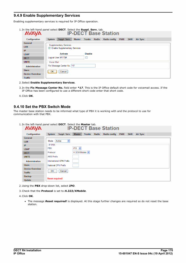
DECT R4 Installation Page 17015-601047 EN-S Issue 04c (19 April 2012)IP Office
9.4.9 Enable Supplementary Services
Enabling supplementary services is required for IP Office operation.
1.In the left-hand panel select DECT. Select the Suppl. Serv. tab.
2.Select Enable Supplementary Services.
3. In the Fix Message Center No. field enter *17. This is the IP Office default short code for voicemail access. If theIP Office has been configured to use a different short code enter that short code.
4.Click OK.
9.4.10 Set the PBX Switch ModeThe master base station needs to be informed what type of PBX it is working with and the protocol to use forcommunication with that PBX.
1.In the left-hand panel select DECT. Select the Master tab.
2.Using the PBX drop-down list, select IPO.
3.Check that the Protocol is set to H.323/XMobile.
4.Click OK.
· The message Reset required! is displayed. At this stage further changes are required so do not reset the basestation.
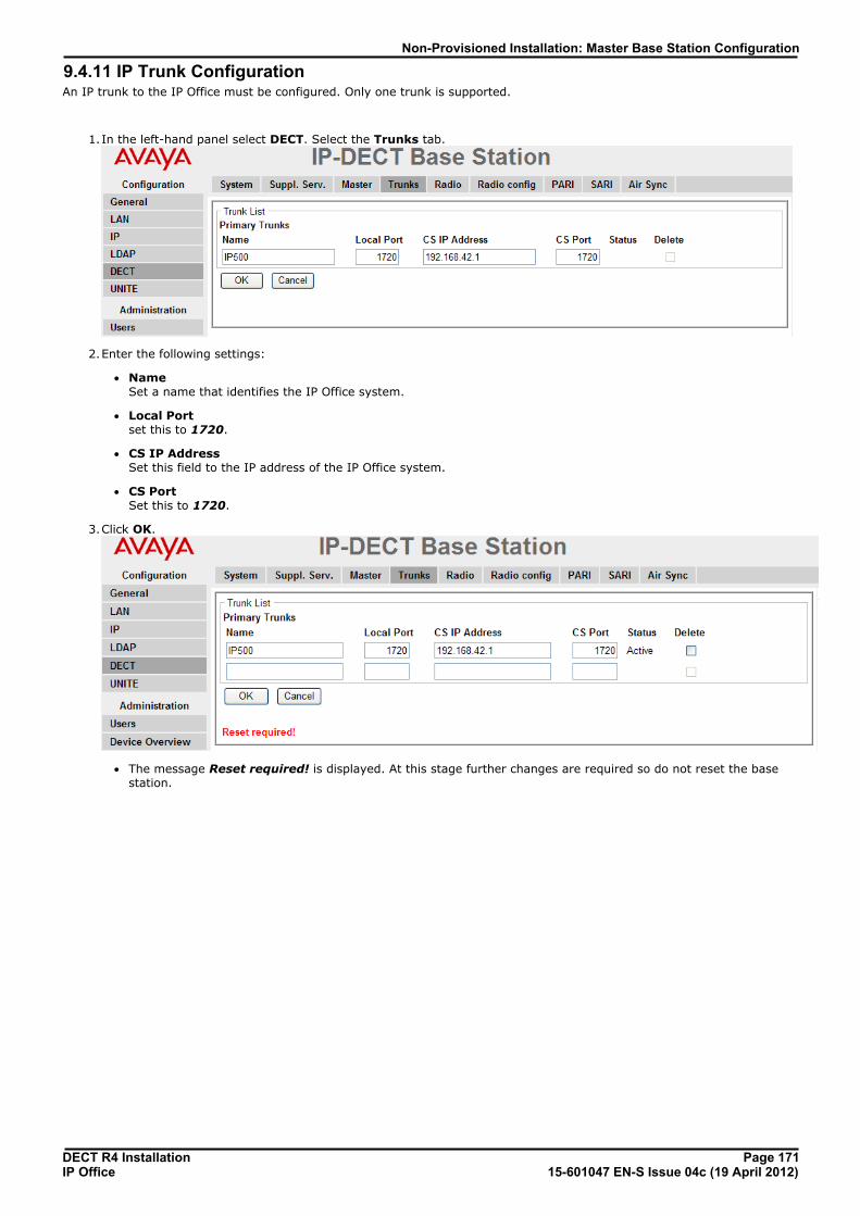
DECT R4 Installation Page 17115-601047 EN-S Issue 04c (19 April 2012)IP Office
Non-Provisioned Installation: Master Base Station Configuration
9.4.11 IP Trunk ConfigurationAn IP trunk to the IP Office must be configured. Only one trunk is supported.
1.In the left-hand panel select DECT. Select the Trunks tab.
2.Enter the following settings:
· Name Set a name that identifies the IP Office system.
· Local Port set this to 1720.
· CS IP Address Set this field to the IP address of the IP Office system.
· CS Port Set this to 1720.
3.Click OK.
· The message Reset required! is displayed. At this stage further changes are required so do not reset the basestation.
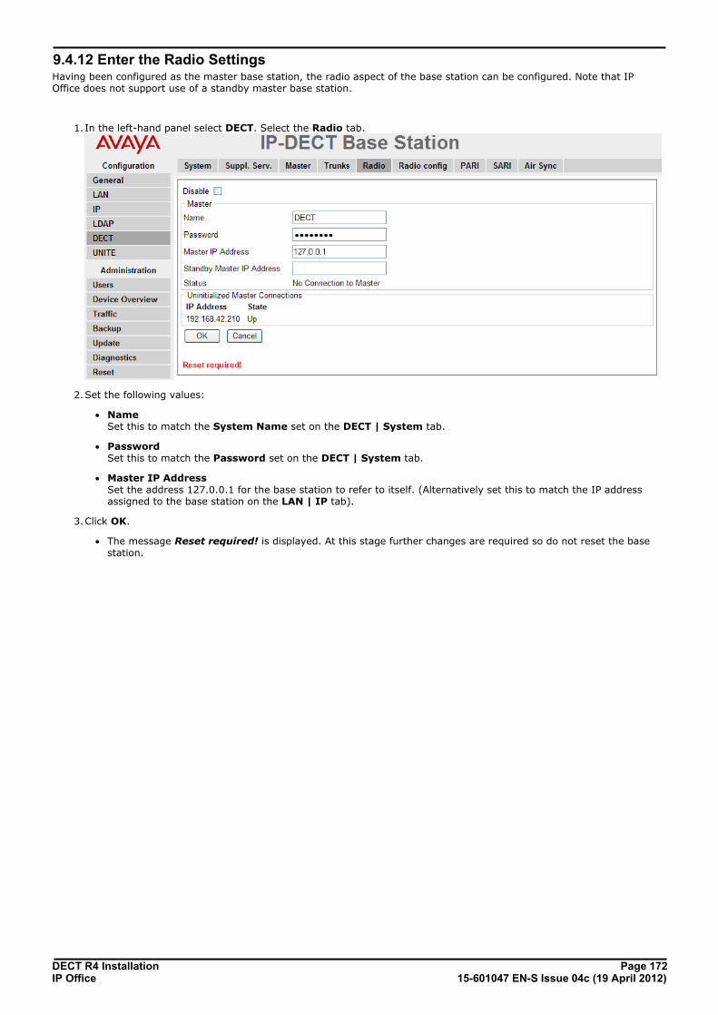
DECT R4 Installation Page 17215-601047 EN-S Issue 04c (19 April 2012)IP Office
9.4.12 Enter the Radio SettingsHaving been configured as the master base station, the radio aspect of the base station can be configured. Note that IPOffice does not support use of a standby master base station.
1.In the left-hand panel select DECT. Select the Radio tab.
2.Set the following values:
· Name Set this to match the System Name set on the DECT | System tab.
· Password Set this to match the Password set on the DECT | System tab.
· Master IP Address Set the address 127.0.0.1 for the base station to refer to itself. (Alternatively set this to match the IP addressassigned to the base station on the LAN | IP tab).
3.Click OK.
· The message Reset required! is displayed. At this stage further changes are required so do not reset the basestation.

DECT R4 Installation Page 17315-601047 EN-S Issue 04c (19 April 2012)IP Office
Non-Provisioned Installation: Master Base Station Configuration
9.4.13 Enter the PARI
1.In the left-hand panel select DECT. Select the PARI tab.
2.Enter a value between 1 and 35. This value must be unique from any other DECT R4 master base station in thearea.
3.Click OK.
9.4.14 Enter the SARI/PARKThe SARI is the license for the DECT R4 system.
1.In the left-hand panel, select DECT. Select the SARI tab.
2.Enter the SARI code provided with the DECT R4 equipment.
3.Click OK.
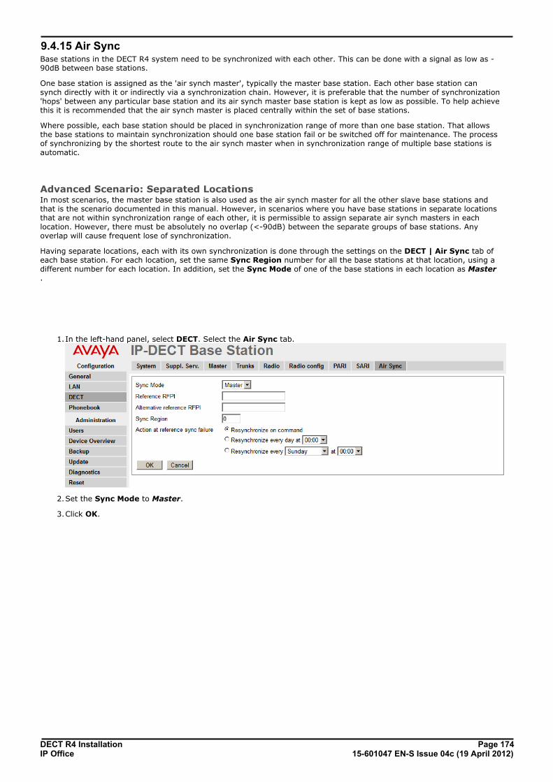
DECT R4 Installation Page 17415-601047 EN-S Issue 04c (19 April 2012)IP Office
9.4.15 Air SyncBase stations in the DECT R4 system need to be synchronized with each other. This can be done with a signal as low as -90dB between base stations.
One base station is assigned as the 'air synch master', typically the master base station. Each other base station cansynch directly with it or indirectly via a synchronization chain. However, it is preferable that the number of synchronization'hops' between any particular base station and its air synch master base station is kept as low as possible. To help achievethis it is recommended that the air synch master is placed centrally within the set of base stations.
Where possible, each base station should be placed in synchronization range of more than one base station. That allowsthe base stations to maintain synchronization should one base station fail or be switched off for maintenance. The processof synchronizing by the shortest route to the air synch master when in synchronization range of multiple base stations isautomatic.
Advanced Scenario: Separated LocationsIn most scenarios, the master base station is also used as the air synch master for all the other slave base stations andthat is the scenario documented in this manual. However, in scenarios where you have base stations in separate locationsthat are not within synchronization range of each other, it is permissible to assign separate air synch masters in eachlocation. However, there must be absolutely no overlap (<-90dB) between the separate groups of base stations. Anyoverlap will cause frequent lose of synchronization.
Having separate locations, each with its own synchronization is done through the settings on the DECT | Air Sync tab ofeach base station. For each location, set the same Sync Region number for all the base stations at that location, using adifferent number for each location. In addition, set the Sync Mode of one of the base stations in each location as Master.
1. In the left-hand panel, select DECT. Select the Air Sync tab.
2.Set the Sync Mode to Master.
3.Click OK.

DECT R4 Installation Page 17515-601047 EN-S Issue 04c (19 April 2012)IP Office
Non-Provisioned Installation: Master Base Station Configuration
9.4.16 IP Office Directory IntegrationFor IP Office Release 6+, the master base station can obtain directory information direct from the IP Office control unitrather than the system requiring an AIWS unit to do this. This requires the master base station to be able to access the IPOffice control unit using TFTP. The directory import is limited to 6000 entries.
Note that enabling directory integration via the master base station disables support for SMS. If both SMS and directoryintegration are required then an AIWS unit must be used.
1.In the left-hand panel, select Phonebook.
2.Select Enable.
3.Select the other settings as shown above, with the Server IP Address set to the IP address of the IP Office controlunit.
4.Click on OK.

DECT R4 Installation Page 17615-601047 EN-S Issue 04c (19 April 2012)IP Office
9.4.17 Reset the Base StationHaving completed the configuration changes, the master base station should be reset.
1.In the left-hand panel, select Reset. Select the Reset tab or Idle-Reset tab.
2.Click OK.
9.4.18 Check the Base StationFollowing the reset, the operation of the radio part can be checked.
1.In the left-hand panel, select DECT. Select the Radio tab.
2.The Status should indicate Connected to Master.
3.The Received Configuration settings should match the parameters entered during configuration.
4.On the base station, LED 2 should be off.

DECT R4 Installation Page 17715-601047 EN-S Issue 04c (19 April 2012)IP Office
Non-Provisioned Installation: Master Base Station Configuration
9.5 IP Slave Base Station ConfigurationThe base station installation process consists of the following stages:
1.Default the base station.
2.Access the base station configuration.
3.Update the base station firmware.
4.Set the base station IP address.
5.Set the base station to slave mode.
6.Reset the base station.
7.Check the base stations.

DECT R4 Installation Page 17815-601047 EN-S Issue 04c (19 April 2012)IP Office
Pre-Requisites· o IP Office connected to the LAN with IP DECT line configured for master base station IP address.
Parts Required· Base station
Includes:
· Base station.
· Two 3.5mm screws and two 6mm wall plugs suitable for wall mounting onto a solid wall (brick or similar).
· 1.2 metre (4 foot) LAN cable. If this is replaced with a longer cable the replacement should be a CAT5 EthernetLAN cable.
· If using Power over Ethernet:
· The base station supports Power over Ethernet, IEEE 802.3af, class 2.
· If not using Power over Ethernet:
· Base station power supply unit. Required if not using Power over Ethernet to power the base station. Note that the base station power supplyunits include an 8 metre (26 feet) cable from the PSU to the base station. Check that you have the correct typeof power supply unit for the locale.
· BSX-0013: Europe (except United Kingdom).
· BSX-0014: United Kingdom.
· BSX-0015: USA/Canada.
· BSX-0016: Australia.
· Mains power outlet socket.
· LAN Socket.
Information· DECT R4 SARI.
· Base Station IP Addresses.
· Detailed plans from the site survey indicating the intended base station locations, LAN sockets and if necessarypower supply outlets.
Tools· Programming PC with DECT R4 software.
· Web browser.
· Drill and drill bits suitable for the selected wall mounting position of the AIWS.
· Screwdrivers for use with the screws selected for AIWS wall mounting.

DECT R4 Installation Page 17915-601047 EN-S Issue 04c (19 April 2012)IP Office
Non-Provisioned Installation: IP Slave Base Station Configuration
9.5.1 Default the Base StationThis process will default a base station or IP DECT Gateway, erasing its configuration. After the unit restarts it will defaultto the IP address 192.168.0.1/255.255.255.0.
1.With the unit not connected to anything else, connect the power supply and switch on.
2.Wait approximately 5 seconds.
3.Using a fine point, depress the unit's reset switch for at least 10 seconds.
4.Release the switch. The unit will restart.
5.After approximately 5 seconds the unit will default to the address 192.168.0.1.
Alternate MethodThe address an existing base station or IP DECT Gateway is using can be determined using the following process. It usesthe MAC address of the unit which is printed on a label on the back or bottom of the unit.
1.Open a Windows command window by selecting Start | Run and enter cmd.
2.Enter nbtstat -R. The PC should respond that is has purged and reloaded the NBT remote cache table.
3.For a base station enter nbtstat -a ipbs-xx-xx-xx when xx-xx-xx is replaced with the last 6 hexadecimal digits ofthe base stations MAC address. For a IP DECT Gateway, enter nbtstat -a ipbl-xx-xx-xx.
4.The results will show the IP address which it being used.
4.Use that address to access the base stations configuration and set it to a fixed address.

DECT R4 Installation Page 18015-601047 EN-S Issue 04c (19 April 2012)IP Office
9.5.2 Access the Base Station's Configuration1.Depending on whether DHCP is being used or not:
· If connected directly to the base station, change your programming PC's network address to 192.168.0.200with subnet mask 255.255.255.0. Connect the LAN cable from your PC to the base station.
· If both your PC and the base station are connected to a LAN network with DHCP server, ensure your PC is setto act as a DHCP client or has a fixed address that is valid on the network.
2.Start your web browser and enter the http:// or https:// followed by the IP address of the base station. The defaultIP address is 192.168.0.1. If a security certificate warning is displayed, select to continue to this website.
3.The base station should respond with its initial configuration menu.
4.Select System administration. A password entry dialog will be displayed. Enter the default user name (admin)and password (changeme).
5.The configuration menu for the base station is displayed.
6.Note the software levels shown in the Version screen. These will determine whether the base station software needsto be upgraded.
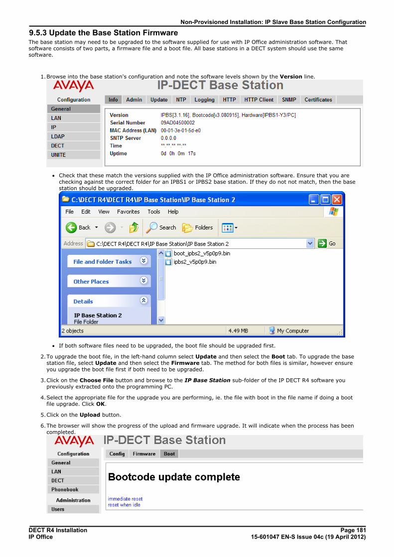
DECT R4 Installation Page 18115-601047 EN-S Issue 04c (19 April 2012)IP Office
Non-Provisioned Installation: IP Slave Base Station Configuration
9.5.3 Update the Base Station FirmwareThe base station may need to be upgraded to the software supplied for use with IP Office administration software. Thatsoftware consists of two parts, a firmware file and a boot file. All base stations in a DECT system should use the samesoftware.
1.Browse into the base station's configuration and note the software levels shown by the Version line.
· Check that these match the versions supplied with the IP Office administration software. Ensure that you arechecking against the correct folder for an IPBS1 or IPBS2 base station. If they do not not match, then the basestation should be upgraded.
· If both software files need to be upgraded, the boot file should be upgraded first.
2.To upgrade the boot file, in the left-hand column select Update and then select the Boot tab. To upgrade the basestation file, select Update and then select the Firmware tab. The method for both files is similar, however ensureyou upgrade the boot file first if both need to be upgraded.
3.Click on the Choose File button and browse to the IP Base Station sub-folder of the IP DECT R4 software youpreviously extracted onto the programming PC.
4.Select the appropriate file for the upgrade you are performing, ie. the file with boot in the file name if doing a bootfile upgrade. Click OK.
5.Click on the Upload button.
6.The browser will show the progress of the upload and firmware upgrade. It will indicate when the process has beencompleted.
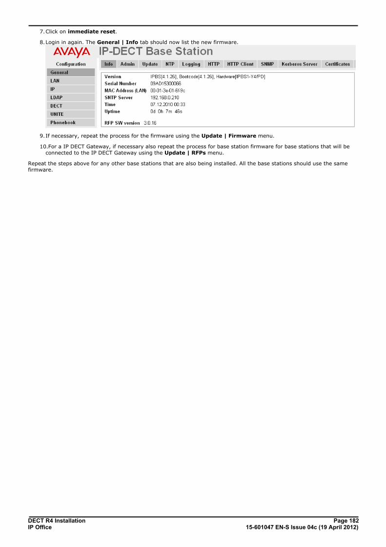
DECT R4 Installation Page 18215-601047 EN-S Issue 04c (19 April 2012)IP Office
7.Click on immediate reset.
8.Login in again. The General | Info tab should now list the new firmware.
9.If necessary, repeat the process for the firmware using the Update | Firmware menu.
10.For a IP DECT Gateway, if necessary also repeat the process for base station firmware for base stations that will beconnected to the IP DECT Gateway using the Update | RFPs menu.
Repeat the steps above for any other base stations that are also being installed. All the base stations should use the samefirmware.

DECT R4 Installation Page 18315-601047 EN-S Issue 04c (19 April 2012)IP Office
Non-Provisioned Installation: IP Slave Base Station Configuration
9.5.4 Set the Base Station IP AddressBy default a base station defaults to 192.168.0.1. The process below can be used to change the DHCP mode and IPaddress of the base station.
1.Having browsed into the base station's configuration, in the left-hand column select LAN.
2.Select the IP tab.
a. Enter the required IP Address and Network Mask for the base station. The other settings are optional.
b.Click OK.
3.Select the DHCP tab.
a.Using the Mode drop-down, select Disabled.
b.Click OK.
4.The menu will prompt you with the message Reset Required. Do not click this or reset the base station at thisstage.
a.Select Reset and then select the Reset tab.
b.Click on OK.
c. Observing the base station, wait for the lower light to return to solid green.
5.Log in again using the new IP address.

DECT R4 Installation Page 18415-601047 EN-S Issue 04c (19 April 2012)IP Office
9.5.5 Set the Base Station to Slave ModeThere can be only 1 master base station in the IP Office DECT R4 system. In this process we check that the base station isnot set to act as a master and then configure its radio settings to access the master base station.
1.In the left-hand column, select DECT. Select the Master tab.
2.Check that the Mode is set to Off.
3.Click OK.
4.Select the Radio tab.
5.Set the following details:
· Name Set this to match the System Name set on the master base station's DECT | System tab.
· Password Set this to match the Password set on the master base station's DECT | System tab.
· Master IP Address Enter the IP address of the master base station set on its LAN | IP tab.
6.Click OK.

DECT R4 Installation Page 18515-601047 EN-S Issue 04c (19 April 2012)IP Office
Non-Provisioned Installation: IP Slave Base Station Configuration
7.Select the Air Sync tab.
8.Set the Sync Mode to Slave.
9.Enable LED Indication. This enables the amber flashing mode of the base station's LED 2 which is used to indicatewhen the base station has no air synchronization signal but does have call traffic in progress.
10.Click OK.
9.5.6 Reset the Base Station1.In the left-hand panel, select Reset. Select the Reset tab or Idle-Reset tab.
2.Click OK.

DECT R4 Installation Page 18615-601047 EN-S Issue 04c (19 April 2012)IP Office
9.5.7 Check the Base StationsThrough the configuration of the slave and the master base status it is possible to check the signalling between the basestations.
Slave Base Station1.In the left-hand column select Device Overview. Select the Air Sync tab.
Master Base Station1.In the left-hand column select Device Overview. Select the Radios tab. The details of the base stations within
the system are displayed.
2.Select the Air Sync tab. The status of wireless synchronization between the master and other base stations isdisplayed.
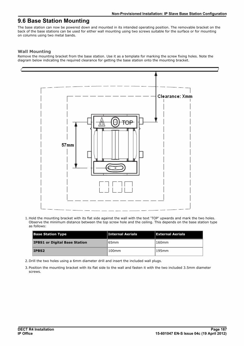
DECT R4 Installation Page 18715-601047 EN-S Issue 04c (19 April 2012)IP Office
Non-Provisioned Installation: IP Slave Base Station Configuration
9.6 Base Station MountingThe base station can now be powered down and mounted in its intended operating position. The removable bracket on theback of the base stations can be used for either wall mounting using two screws suitable for the surface or for mountingon columns using two metal bands.
Wall MountingRemove the mounting bracket from the base station. Use it as a template for marking the screw fixing holes. Note thediagram below indicating the required clearance for getting the base station onto the mounting bracket.
1.Hold the mounting bracket with its flat side against the wall with the text ‘TOP’ upwards and mark the two holes.Observe the minimum distance between the top screw hole and the ceiling. This depends on the base station typeas follows:
Base Station Type Internal Aerials External Aerials
IPBS1 or Digital Base Station 65mm 160mm
IPBS2 100mm 195mm
2.Drill the two holes using a 6mm diameter drill and insert the included wall plugs.
3.Position the mounting bracket with its flat side to the wall and fasten it with the two included 3.5mm diameterscrews.

DECT R4 Installation Page 18815-601047 EN-S Issue 04c (19 April 2012)IP Office
Column/Pillar MountingThe mounting bracket can be fixed to a pole of 45mm diameter or greater, or a beam of 50mm width minimum by using astrap or flexible metal band less than 30 mm wide. A suitable strap or flexible metal band is not included with the basestation.

DECT R4 Installation Page 18915-601047 EN-S Issue 04c (19 April 2012)IP Office
Non-Provisioned Installation: Base Station Mounting
9.7 Phone SubscriptionOnce the master base station has been configured and is connected to the IP Office, you can begin phone subscription.
There are two methods of subscription; anonymous phone subscription and pre-configured phone subscription. Bothmethods require the DECT users to be pre-configured in the master base station configuration. However, anonymousphone subscription allows the user pre-configuration to be done without knowing the IPEI of the DECT phone the user willactually use.
· Subscription Using IP Office Auto-Create Allowing phone subscription using the IP Office auto-create options for extensions and or users makeschanges to the current running configuration of the IP Office system. For this method to work, youmust ensure that no copies of the configuration are also open in Manager during subscription, assending such a copy of the configuration back to the IP Office system will replace the subscriptionsand require the handsets to be subscribed again. Following any handset subscription, a new copy ofthe configuration should always be loaded in IP Office Manager if any other configuration changes arerequired.
The anonymous phone installation process consists of the following stages:
1.Allow Subscription.
2.Create User Entries in the Master Base Station Configuration.
3.Subscribe the Phones.
4.Complete Anonymous Login.
5.Disable Subscription.
· This method makes changes to the IP Office system configuration. Ensure that no copies of the configuration are openin Manager during subscription as sending that configuration back to the IP Office system will remove the subscriptionsand require the handsets to be resubscribed.
Pre-Requisites· o Master base station installed and connected to the network.
· o IP Office connected to the network.
Information· Service user name and password for IP Office configuration.
· User names and extension numbers for the DECT phones.
· Phone IPEI numbers if using an pre-configured installation mode.
Tools· IP Office Manager.
· Device Manager The software installed on each handset may need to be upgraded to match that supplied with the DECT R4 software
. This is done using the Windows Device Manager software to upgrade phones via an advanced charger orusing AIWS Device Manager to upgrade phones over the air.
· Web browser (Internet Explorer or Firefox are supported).
34
95

DECT R4 Installation Page 19015-601047 EN-S Issue 04c (19 April 2012)IP Office
9.7.1 Allow SubscriptionBefore phones are subscribed subscription needs to be allowed by both the IP Office and the DECT R4 system.
IP Office1.Start IP Office Manager and receive the configuration from the IP Office system.
2.In the left-hand navigation pane, click on Line icon.
3.Select the IP DECT Line.
4.Select the Gateway tab.
5.Check that the Auto-Create Extension and Auto-Create User options are selected.
· Subscription Using IP Office Auto-Create Allowing phone subscription using the IP Office auto-create options for extensions and or users makeschanges to the current running configuration of the IP Office system. For this method to work, youmust ensure that no copies of the configuration are also open in Manager during subscription, assending such a copy of the configuration back to the IP Office system will replace the subscriptionsand require the handsets to be subscribed again. Following any handset subscription, a new copy ofthe configuration should always be loaded in IP Office Manager if any other configuration changes arerequired.
6.Click OK.
7.Send the configuration back to the IP Office.
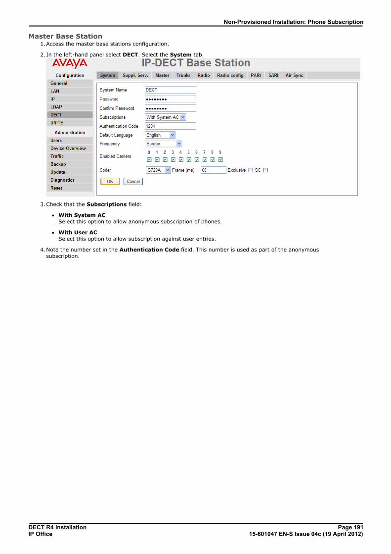
DECT R4 Installation Page 19115-601047 EN-S Issue 04c (19 April 2012)IP Office
Non-Provisioned Installation: Phone Subscription
Master Base Station1.Access the master base stations configuration.
2.In the left-hand panel select DECT. Select the System tab.
3.Check that the Subscriptions field:
· With System AC Select this option to allow anonymous subscription of phones.
· With User AC Select this option to allow subscription against user entries.
4.Note the number set in the Authentication Code field. This number is used as part of the anonymoussubscription.

DECT R4 Installation Page 19215-601047 EN-S Issue 04c (19 April 2012)IP Office
9.7.2 Create User EntriesSubscription requires a user entry within the master base station configuration. On completion of subscription, matchingextension and user entries are automatically created in the IP Office configuration.
1.In the left-hand panel, select Users. Select the Users tab.
2.Click new. A dialogue is displayed for entry of user details.
3.Enter the user details:
· Long Name This name is used for information within the DECT R4 system settings.
· Display Name This name displayed on the phone when idle. It is also the name used for the user created in the IP Officeconfiguration. The name must be unique.
· Number This will be the extension number of the phone on both the IP Office and DECT R4 systems. The number mustbe unique.
The remaining two fields should not be completed if you want to use anonymous subscription. This removes therequirement of knowing the phone IPEI numbers during installation.
· IPEI/IPDI Enter the phones IPEI number. For 3720, 3725 phones this is printed on the label inside the phones batterycompartment.
· For 3720, 3725, 3740 and 3749 phones, the IPEI can be displayed by selecting Menu | Settings |Device Info | IPEI/IPDI. It is also printed on a label under the phone's battery.
· Auth. Code Enter the account code that should be used when the phone is subscribed.
4.Click OK.
5.Repeat the process for any other phones that you want to subscribe.
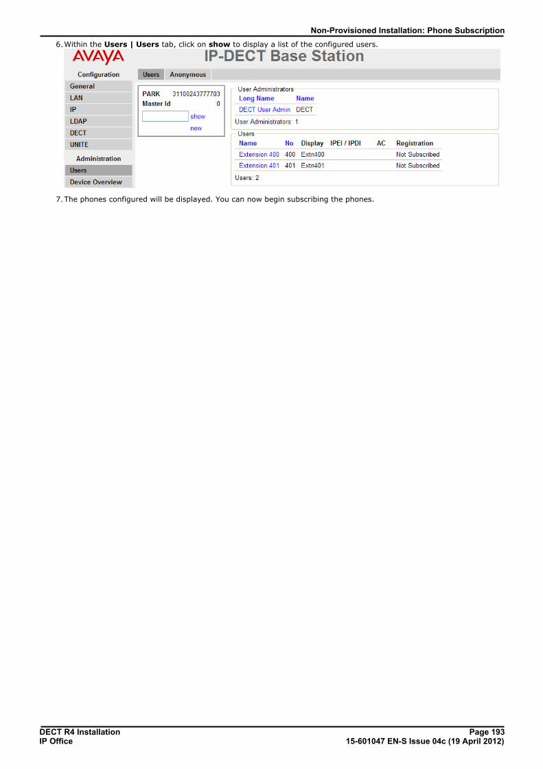
DECT R4 Installation Page 19315-601047 EN-S Issue 04c (19 April 2012)IP Office
Non-Provisioned Installation: Phone Subscription
6.Within the Users | Users tab, click on show to display a list of the configured users.
7.The phones configured will be displayed. You can now begin subscribing the phones.

DECT R4 Installation Page 19415-601047 EN-S Issue 04c (19 April 2012)IP Office
9.7.3 Phone Subscription· Switch on the phone:
· 3720: Select Menu | Settings | System | Subscribe.
· 3725/3740/3749: Select Menu | Connections | System | Subscribe.
Display Actions
Details of the phone's current subscription are displayed. Select Next.
The System name is just used by the phone to identify the different subscriptions itmay have.
Enter any name and select Next.
The phone will display a list of telephone system types to which it can connect. Scroll theselected option to IP-DECT and select Next.
The phone now requires the PARK (SARI) and AC (authentication code) of the system towhich it should subscribe.
Enter the PARK and then scroll to the AC field.
Enter the AC and select Next.
The Protection on? prompt is displayed.
· If you select No, the user can delete the subscription from the list of subscriptionsknown by the phone.
· If you select Yes, the user cannot delete the subscription.
A summary of the subscription details is shown. Check that the values are correct

DECT R4 Installation Page 19515-601047 EN-S Issue 04c (19 April 2012)IP Office
Non-Provisioned Installation: Phone Subscription
Display Actions
Select OK.
The phone broadcast for DECT systems to which it can subscribe.
When a DECT system is located, the handset will attempt to subscribe to that system.
The success or failure of the subscription is indicated.
3701/3711 Phone Subscription1.Switch on the phone.
2.Select Menu | System | Subscription | Subscribe HS.
3.Select PABX-PIN.
4.Enter the authentication code.
5.The phone is subscribed anonymously and should display Please Login.

DECT R4 Installation Page 19615-601047 EN-S Issue 04c (19 April 2012)IP Office
9.7.4 Completing Anonymous LoginIn the master base station configuration select the Users | Anonymous tab. This tab shows those phones currentlyanonymously subscribed to the DECT system. The DECT system will allow up to 8 anonymous devices to be subscribed atthe same time.
This process changes the anonymous subscription to a known subscription. While a phone is in anonymoussubscription state it displays a screen showing Please login.
1.To login, dial *M*N# where:
· M is the DECT system's Master Id. This is shown on the base station's Users | Users tab.
· N is the extension number required. This must match an existing unsubscribed user entry on the Users |Users tab in the master base station configuration.
2.For example, on a system with master ID 0, to register an anonymously subscribed device as extension 403, dial*0*403#.
196
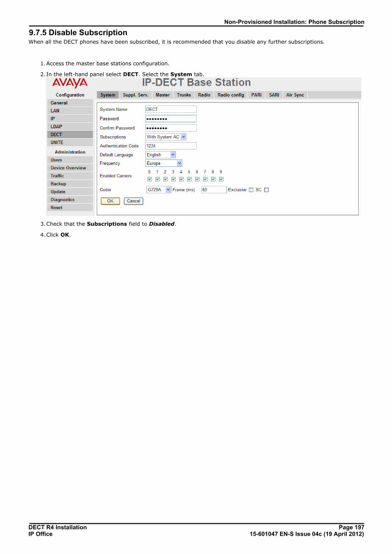
DECT R4 Installation Page 19715-601047 EN-S Issue 04c (19 April 2012)IP Office
Non-Provisioned Installation: Phone Subscription
9.7.5 Disable SubscriptionWhen all the DECT phones have been subscribed, it is recommended that you disable any further subscriptions.
1.Access the master base stations configuration.
2.In the left-hand panel select DECT. Select the System tab.
3.Check that the Subscriptions field to Disabled.
4.Click OK.

DECT R4 Installation Page 19815-601047 EN-S Issue 04c (19 April 2012)IP Office

DECT R4 Installation Page 19915-601047 EN-S Issue 04c (19 April 2012)IP Office
Glossary
Chapter 10.
DECT R4 Installation Page 20015-601047 EN-S Issue 04c (19 April 2012)IP Office
10. GlossaryThe following are definitions for common abbreviations used within the DECT R4 system applications.
10.1 AIWSAvaya In-Building Wireless Server
10.2 IPBSIP-DECT Base Station
10.3 SSSignal Strength
10.4 SARIAn alternate name for the PARK .
10.5 PARIPrimary Access Right Identity
10.6 PARKPortable Access Rights Key
10.7 FERFrame Error Rate
10.8 DECTDigital Enhanced Cordless Telecommunications - Global standard for cordless telephony.
10.9 CAPCommon Access Profile
10.10 GAPGeneric Access Profile - Standard used for DECT.
10.11 IPDIAt delivery of the telephone, IPEI and IPDI are the same and either can be used for network subscription. If one telephoneis replaced with another using the Easy replacement procedure the IPDI will be exchanged and IPEI and IPDI will no longerbe the same. If the IPEI and the IPDI differ, the IPDI shall be used for network subscription.
10.12 IPEIInternational Portable Equipment Identity - The unique global GAP identity number for the phone. This code isneeded for the system administrator to enable network subscription.
10.13 PBXPBX Private Branch Exchange - Telephone system within an enterprise that switches calls between local lines andallows all users to share a certain number of external lines.
10.14 PDMPortable Device Manager
10.15 WSMWireless Services and Message -Module that enables wireless services like central phone book and messaging to andfrom the portable devices. An alternate term for the AIWS .
10.16 ELISEEmbedded LInux SErver - A term for the AIWS .
10.17 SSTSite Survey Tool
10.18 PPPortable Part - A term for DECT phones.
200
200
200

DECT R4 Installation Page 20115-601047 EN-S Issue 04c (19 April 2012)IP Office
Glossary: RFP
10.19 RFPRadio Fixed Part - A term for DECT base-stations.
10.20 RFPIRadio Fixed Part Identity.


DECT R4 Installation Page 20315-601047 EN-S Issue 04c (19 April 2012)IP Office
Index
Index**17 170
11720 171192.168.0.1 44, 55, 161, 179
33720 7, 15
3725 7, 153725 Site Survey Mode 28
AAerials 10, 13
Air Sync 174
air synch master 27, 174AIWS 7, 20
Browse 126
Cover 124
Device Manager 92, 95Installation 122IP Address 110, 127
Replacing the Cover 140
Status Lamp 140, 148Switch Off 139Upgrade 117, 134
Wall Mount 139
Allow Subscription 190Anonymous Login 196Antenna 13
Auth. Code 192
Authentication Code 168, 190Auto-Create Extension 38, 157Auto-Create User 38, 157
Avaya In-Building Wireless Server 7, 20
BBase Station 7, 10
Access the Configuration 45, 56, 162, 180Browse 45, 56, 162, 180
IP Address 46, 57, 165, 183
Mounting 61, 82, 187Reset 176, 185Reset Switch 144
Restart 144
Status Lamps 144Time Source 166
Battery 15
AIWS 125
RTC 125Bear 28Bluetooth 15
Bracket 10
Browse AIWS 126Base Stations 45, 56, 162, 180
BS330 10
BS340 10, 13Building Layout 28
CC7 S10 28
Call list 15
CAP 15Chargers
Advanced Charger 7, 19
Basic Charger 7, 19
Battery Charger 7, 19
Rack Charger 7, 19Class 2 10Column Mounting 61, 82, 187
Compact Base Station 7, 10
Cover Remove 124Replacing 140
Coverage 25
Coverage pattern 10Create User Entries 192CS IP Address 171
CS Port 171
DDate and Time 110, 127DECT 7DECT Info 28
DECT phones 15
DECT R4.zip 34, 154Default Language 168default the base station 44, 55, 161, 179
Defintion Files
Upload 65, 96Device Manager 95
AIWS 92
WinPDM 92
Device Overview 186Directional Dual Aerial 13Directional Single Antenna 13
Directory Integration 7, 175
Disable Subscription 197Display Name 192
EEdit Templates 102
Enable Supplementary Services 170
Error rate 28External aerials 10
FFactory reset 144
Fire Doors 25
Firmware 34, 47, 58, 154, 163, 181Upgrade Base Station 47, 58, 163, 181
Fix Message Center No 170
Frequency 168
GGAP 15Gateway 38, 157
HHandover 26
Hands free 15
Handset configuration 20Host Name 110, 127
IIdle-Reset 176, 185
IEEE 802.3af 10
Installation AIWS 122
Internal aerials 10
IP Address 44, 55, 161, 179
AIWS 110, 127Base Station IP Address 46, 57, 165, 183
IP DECT Base Station 7
IP DECT Line 38, 157
IP LAN 7

DECT R4 Installation Page 20415-601047 EN-S Issue 04c (19 April 2012)IP Office
IP Office
Directory Integration 175IP Office Release 7IP44 15
IPBS 7
IPDI 192IPEI 192
LLAN sockets 7
Language 168
Languages 15LED Indication 184Local Port 171
Login 196
Long Name 192Loudspeaker 15
MMAC address 44, 55, 161, 179
Master Base Station 10, 168
Configuration 159Master IP Address 172, 184Mounting
AIWS 139
Base Station 61, 82, 187
NName
Display 192
Long 192
NTP Time Server 110, 127Number 192Number of base stations 24
Number of Calls 10
OOmni-Directional 13Overlap 24
PParameter Defintion Files 65, 96
PARI 28, 173
PARK 28, 173Password 168PBX 170
PDM 92
Phone Edit template 102Login 196
Software upgrade 73, 104
Subscription 189Template Files 100
Phone Subscription 194
Phone Templates
Upload 98Phonebook Properties 110, 127Phones 15
Pillar Mounting 61, 82, 187
PoE 10Portable Device Manager 92Power over Ethernet 10
Protocol 170
QQ2 Error rate 28QoS 167
RRack Chargers 25
Radio coverage 10
Range 25
Removing the AIWS Cover 124Replacing the AIWS Cover 140Reset 176, 185
Base Station 176, 185
reset switch 44, 55, 144, 161, 179Restart 144Roaming 26
RTC Battery 125
SS10 28SARI 173Screened Rooms 25
Separated Locations 27, 174
Setup Wizard 110, 127Simultaneous calls 10Site Survey 24
Site Survey Mode 28
Slave Mode 184SMS 7, 15SMS messaging 20
Software 34, 154
Upgrade Base Station 47, 58, 163, 181Software upgrades 20Speech Time 15
ss 28
Stair Wells 25Standby Time 15Starting
AIWS Device Manager 95
Windows Device Manager 95Status Lamp
AIWS 140, 148
Status Lamps
Base Station 144Status Logging 167Subnet Mask 110, 127
Subscription
Allow 190Disable 197Login 196
Phone 194
Phone Subscription 189Subscriptions 168Supplementary Services 170
Supported firmware 34, 154
Switching Off AIWS 139
Sync Mode 184
synchronized 27, 174
System Name 168
TTechnical Bulletin 117, 134Technical Bulletins 34, 154
Technical Tips 34, 154
Template 100Edit 102
TFTP 110, 127
Time
Base Station Time Source 166Speech 15Standby 15
Time Server IP Address 110, 127
ToS 167

DECT R4 Installation Page 20515-601047 EN-S Issue 04c (19 April 2012)IP Office
Index
UUnpack the software 34, 154
Upgrade AIWS Firmware 117, 134Base Station Firmware 47, 58, 163, 181
Phone Software 73, 104
upgraded 47, 58, 163, 181Upload
Parameter Defintion Files 65, 96
Phone templates 98
USB 7, 19
VVibrator 15VoIP 38, 157
WWall Mount
AIWS 139Wall Mounting 61, 82, 187Windows Device Manager 95
Windows Portable Device Manager 92
WinPDM 92Wireless
Handset configuration 20
Software Upgrade 20
With System AC 168, 190With User AC 190


DECT R4 Installation Page 20715-601047 EN-S Issue 04c (19 April 2012)IP Office

DECT R4 Installation Page 20815-601047 EN-S Issue 04c (19 April 2012)IP Office
Performance figures and data quoted in this document are typical, and must bespecifically confirmed in writing by Avaya before they become applicable to anyparticular order or contract. The company reserves the right to make alterationsor amendments to the detailed specifications at its discretion. The publication of
information in this document does not imply freedom from patent or otherprotective rights of Avaya or others.
All trademarks identified by the ® or ™ are registered trademarks or trademarks,respectively, of Avaya Inc. All other trademarks are the property of their
respective owners.
This document contains proprietary information of Avaya and is not to bedisclosed or used except in accordance with applicable agreements.
© 2012 Avaya Inc. All rights reserved.