iowa department of transportation date of letting
TRANSCRIPT

A d d e n d u m
Iowa Department of Transportation Date of Letting: February 21, 2017
Office of Contracts Date of Addendum: February 16, 2017
B.O. Proposal ID Proposal Work Type County Project Number Addendum
104 25-8177-619 PCC PAVEMENT WIDENING DALLAS STP-U-8177(619)—70-25 21FEB104A01
Make the following change to the Proposal Details, Page 2
Change Completion Date:
From: 10/27/17
To: 11/24/17
Make the following changes to the Proposal Special Provisions List and the Proposal Special Provisions
Text.
Replace SP-154009 with the attached SP-154009a
SPECIAL PROVISIONS FOR TRAFFIC SIGNALIZATION
Dallas County STP-U-8177(619)--70-25
Effective Date February 21, 2017
SP-154009a Revisions:
- Remove multimode fiber optic cable
- Changing the model of the PTZ camera to be installed
- Added provision for traffic signal poles, pedestal poles, base mast arms and hardware painting
system allowed
- Updated pole design specification requirement
Replace SP-154013 with the attached SP-154013a
SPECIAL PROVISIONS FOR ELECTRICAL SYSTEM FOR STORMWATER PUMPS
Dallas County STP-U-8177(619)--70-25
Effective Date February 21, 2017
SP-154013 Revisions:
- Revised to specify the Flygt/Xylem MultiStart pump station controller and the Asea Brown
Boveri (ABB) Variable Speed Drive (VFD) motor controller

Make the following changes to the PROPOSAL SCHEDULE OF PRICES:
Change Proposal Line No. 0020 2102-2710070 EXCAVTION, CLASS 10, ROADWAY AND
BORROW:
From: 22,562.000 CY
To: 19,817.000 CY
Change Proposal Line No. 0030 2102-2710090 EXCAVTION, CLASS 10, WASTE:
From: 4,153.000 CY
To: 1,424.000 CY
Change Proposal Line No. 0050 2105-8425015 TOPSOIL, STRIP, SALVAGE AND SPREAD:
From: 7,882.000 CY
To: 7,751.000 CY
Change Proposal Line No. 0660 2523-0000100 LIGHTING POLES:
From: 20.000 EACH
To: 18.000 EACH
Change Proposal Line No. 0680 2523-0000310 HANDHOLES AND JUNCTION BOXES:
From: 23.000 EACH
To: 25.000 EACH
If the above changes are not made, they will be made as shown here.
Replace plans sheets with the attached:
A.01, C.02, C.03, C.08, M.15, M.16, M.17, M.18, M.19, N.01, N.02, N.04, N.05, N.08, T.01,
T.02, T.03, & T.04
C.02 and C.03:
- Revised Items 2, 3, and 5, earthwork quantities, as it was determined that the Class 10 quantity
included portions of the Class 20 excavation for the pedestrian underpass and earthwork was
rerun to detail staging needs per question #5.
- Revised Item 66, Lighting pole, quantity per clarification from Question #6
- Revised Item 68, Handhole quantity per clarification from Question #8.
C.08:
- Strike “Reinforced” from all 10” PCC as joint reinforcement is all that is needed per questions
#10.
M.15-M.19:
- Revised to depict the wetwell level sensor and float switches to reflect the configuration change
of the level sensor and back-up level detector (Multitrode).
- Updated the I/O Schedule and field wiring schedule to show one less point used for the back-up
scheme.

N.01:
- Project notes were revised to remove ground rods adjacent to each handhole, removed required
pain method as powder coating, removed mention of luminaires and refers to P-sheets for
information, and added a note to coordinate splicing of the fiber optic cable with the City.
- Quantities were updated to reflect other sheet changes
- Quantities for EVP detector, Fiber termination rack 24 Position, 7c signal cable, and 5c signal
cable were added per question #7.
N.02:
- Signal head arrangement was changed and Fiber hub was removed from item list.
N.04:
- 72 SM was removed, 12MM was replaced with 12 SM, Note 12 and 13 were removed completely
including 2” conduit
N.05:
- Detectors 60A,60B,60C were combined to one card rack position and card rack was changed to a
Two channel Detector.
N.08:
- Splice diagram was added.

SP-154009a (Replaces SP-154009)
SPECIAL PROVISIONS FOR
TRAFFIC SIGNALIZATION
Dallas County STP-U-8177(619)--70-25
Effective Date
February 21, 2017
THE STANDARD SPECIFICATIONS, SERIES 2015, ARE AMENDED BY THE FOLLOWING MODIFICATIONS AND ADDITIONS. THESE ARE SPECIAL PROVISIONS AND THEY SHALL PREVAIL OVER THOSE PUBLISHED IN THE STANDARD SPECIFICATIONS.
154009a.01 DESCRIPTION. Includes the furnishing of all material and equipment necessary to complete, in place and operational, traffic control signal(s) as described in the project plans. A. Submittals
1. Follow the General Provisions (Requirements) and Covenants as well as the additional requirements listed below. All of the following must be submitted within 30 days after awarding of the contract for the project. Verify the method of submittal with the Jurisdiction.
2. Schedule of Unit Prices: Submit a completed schedule of unit prices. Estimates of the work performed on the project will be made by the Jurisdiction and the unit costs will be used to prepare progress payments to the Contractor.
3. Material and Equipment List: Submit a completed list of materials and equipment to the Jurisdiction for written approval before any equipment or materials are ordered.
4. Contractor Certification: Submit the name(s) and contact information of the International Municipal Signal Association (IMSA) Level II Certified Traffic Signal Technician(s) working on the project and a copy of their IMSA certificate.
5. Shop Drawings: Submit shop drawings for traffic signal poles and structures to be furnished on the project. Submit catalog cuts and manufacturer’s specifications for all items in the equipment list.
B. Special Requirements
1. The installation of the traffic control signals and appurtenances shall comply with the current edition of the MUTCD as adopted by the Iowa DOT.
2. The Contractor shall be responsible for ONE CALL locates of the fiber cables installed under this project until acceptance of the project by the City.
3. The Contractor shall coordinate with the City for splice connections of the fiber into the existing fiber optic system. The Contractor to supply fiber optic wiring diagram as-built drawings. The Contractor shall maintain accurate quantities of the splices and terminations at each location during the project.
154009a.02 MATERIALS. A. Underground
1. Handhole: a. General:
i. Cable Hooks: Provide four galvanized steel cable hooks with a minimum diameter of 3/8 inch and a minimum length of 5 inches.
SP-154009a, Page 2 of 16
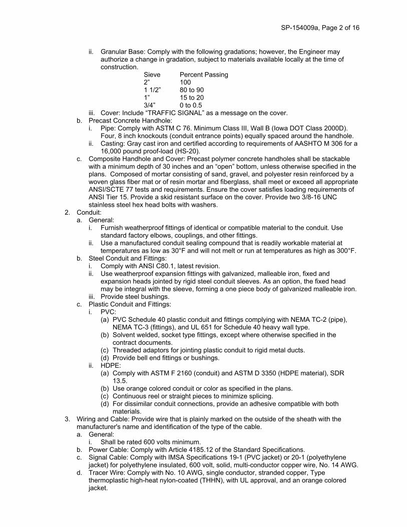
ii. Granular Base: Comply with the following gradations; however, the Engineer may authorize a change in gradation, subject to materials available locally at the time of construction.
Sieve Percent Passing 2” 100 1 1/2” 80 to 90 1” 15 to 20 3/4” 0 to 0.5
iii. Cover: Include “TRAFFIC SIGNAL” as a message on the cover. b. Precast Concrete Handhole:
i. Pipe: Comply with ASTM C 76. Minimum Class III, Wall B (Iowa DOT Class 2000D). Four, 8 inch knockouts (conduit entrance points) equally spaced around the handhole.
ii. Casting: Gray cast iron and certified according to requirements of AASHTO M 306 for a 16,000 pound proof-load (HS-20).
c. Composite Handhole and Cover: Precast polymer concrete handholes shall be stackable with a minimum depth of 30 inches and an “open” bottom, unless otherwise specified in the plans. Composed of mortar consisting of sand, gravel, and polyester resin reinforced by a woven glass fiber mat or of resin mortar and fiberglass, shall meet or exceed all appropriate ANSI/SCTE 77 tests and requirements. Ensure the cover satisfies loading requirements of ANSI Tier 15. Provide a skid resistant surface on the cover. Provide two 3/8-16 UNC stainless steel hex head bolts with washers.
2. Conduit: a. General:
i. Furnish weatherproof fittings of identical or compatible material to the conduit. Use standard factory elbows, couplings, and other fittings.
ii. Use a manufactured conduit sealing compound that is readily workable material at temperatures as low as 30°F and will not melt or run at temperatures as high as 300°F.
b. Steel Conduit and Fittings: i. Comply with ANSI C80.1, latest revision. ii. Use weatherproof expansion fittings with galvanized, malleable iron, fixed and
expansion heads jointed by rigid steel conduit sleeves. As an option, the fixed head may be integral with the sleeve, forming a one piece body of galvanized malleable iron.
iii. Provide steel bushings. c. Plastic Conduit and Fittings:
i. PVC: (a) PVC Schedule 40 plastic conduit and fittings complying with NEMA TC-2 (pipe),
NEMA TC-3 (fittings), and UL 651 for Schedule 40 heavy wall type. (b) Solvent welded, socket type fittings, except where otherwise specified in the
contract documents. (c) Threaded adaptors for jointing plastic conduit to rigid metal ducts. (d) Provide bell end fittings or bushings.
ii. HDPE: (a) Comply with ASTM F 2160 (conduit) and ASTM D 3350 (HDPE material), SDR
13.5. (b) Use orange colored conduit or color as specified in the plans. (c) Continuous reel or straight pieces to minimize splicing. (d) For dissimilar conduit connections, provide an adhesive compatible with both
materials. 3. Wiring and Cable: Provide wire that is plainly marked on the outside of the sheath with the
manufacturer's name and identification of the type of the cable. a. General:
i. Shall be rated 600 volts minimum. b. Power Cable: Comply with Article 4185.12 of the Standard Specifications. c. Signal Cable: Comply with IMSA Specifications 19-1 (PVC jacket) or 20-1 (polyethylene
jacket) for polyethylene insulated, 600 volt, solid, multi-conductor copper wire, No. 14 AWG. d. Tracer Wire: Comply with No. 10 AWG, single conductor, stranded copper, Type
thermoplastic high-heat nylon-coated (THHN), with UL approval, and an orange colored jacket.

SP-154009a, Page 3 of 16
e. Communications Cable: Comply with IMSA Specifications 39-2 or 40-2 for No. 19 AWG, solid copper conductor, twisted pairs. Use polyethylene insulated, aluminum shielded, complying with REA Specification PE-39 for paired communication cable with electrical shielding.
f. Category 5E (Cat5E) Cable: Provide outdoor use rated cable. g. Fiber Optic Cable and Accessories:
i. Furnish fiber optic cable of the mode type, size, and number of fibers specified in the contract documents, and all associated accessories.
ii. Meet the latest applicable standard specifications by ANSI, Electronics Industries Association (EIA), and Telecommunications Industries Association (TIA).
iii. Multimode Fiber – Grade Index: Core Diameter: 62.5 μm ± 1.0 μm Cladding Diameter: 125.0 μm ± 1.0 μm Core Concentricity: ± 1% Max. Attenuation: 3.75 dB/km @ 850 nm
iv. Single-Mode Fiber: Typical Core Diameter: 8.3 μm ± 1.0 μm Cladding Diameter: 125.0 μm ± 1.0 μm Core Concentricity: ± 1% Attenuation Uniformity: No point discontinuity greater than 0.1 um at
either 1310 nm or 1550 nm Max. Attenuation: 0.25 dB/km
v. Dual layer UV cured acrylate coating applied by the fiber manufacturer, mechanically or chemically strip-able without damage to the fiber.
vi. Glass reinforced plastic rod central member designed to prevent the buckling of the cable. Cable core interstices filled with water blocking tape to prevent water infiltration.
vii. Dielectric fillers may be included in the cable core where needed to lend symmetry to the cable cross-section.
viii. Buffer tubes of dual layer construction with a polycarbonate inner layer and polyester outer layer. Each buffer tube filled with a water-swellable yarn or tape. Buffer tubes stranded around the central member using reverse oscillation or “SZ” stranding process. Gel-free cable and buffer tubes.
ix. Buffer tubes and fibers meeting TIA/EIA-598A, “Color coding of fiber optic cables.” The single mode cable shall include loose tubes with 12 fibers in each with a total number of tubes matching the number of fibers specified on the plans. The multimode cable shall include one loose tube with 12 fibers. The tube and fiber colors shall follow the industry color code (BL, OR, GR, BR, SL, WH, RD, BK, YL, VI, RS, AQ).
x. Cable tensile strength provided by a high tensile strength aramid yarn and/or fiberglass. xi. All dielectric cables, without armoring, sheathed with medium density polyethylene (1.4
mm minimum nominal jacket thickness). Jacketing material applied directly over the tensile strength members and flooding compound. Jacket or sheath marked in a contrasting color with the manufacturer's name and the words “Optical Cable,” the year of manufacture, and sequential meter or feet marks. The markings shall be repeated every meter. The actual length of the cable shall be within the range plus one percent of the length marked. Additionally, provide a durable weather proof label on the cable jacket showing the actual attenuation of each fiber expressed in dB/km.
xii. Cable fabricated to withstand a maximum pulling tension of 600 pounds during installation (short term) and 135 pounds upon installation (long term).
xiii. Shipping, storing, and operating temperature range of the cable: -40°F to +160°F. xiv. Each fiber of all fiber optic cable tested by manufacturer at the 100% level for the
following tests: (a) Proof tested at a minimum load of 50 kpsi (b) Each fiber shall be tested for attenuation and the reading shall be part of the cable
labeling. (c) Meet the appropriate standard Fiber Optic Test Procedure for the following
measurements: Fluid Penetration Compound Drip Compressive Loading Resistance
SP-154009a, Page 4 of 16
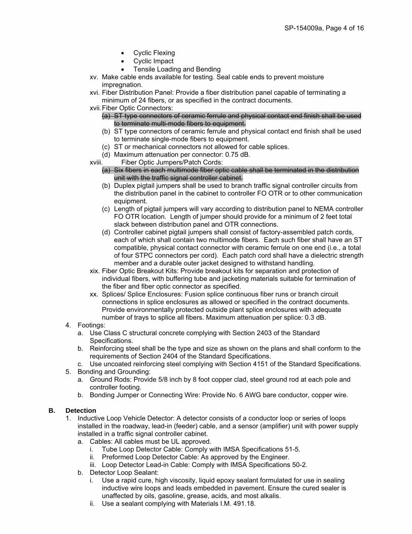
Cyclic Flexing Cyclic Impact Tensile Loading and Bending
xv. Make cable ends available for testing. Seal cable ends to prevent moisture impregnation.
xvi. Fiber Distribution Panel: Provide a fiber distribution panel capable of terminating a minimum of 24 fibers, or as specified in the contract documents.
xvii. Fiber Optic Connectors: (a) ST type connectors of ceramic ferrule and physical contact end finish shall be used
to terminate multi-mode fibers to equipment. (b) ST type connectors of ceramic ferrule and physical contact end finish shall be used
to terminate single-mode fibers to equipment. (c) ST or mechanical connectors not allowed for cable splices. (d) Maximum attenuation per connector: 0.75 dB.
xviii. Fiber Optic Jumpers/Patch Cords: (a) Six fibers in each multimode fiber optic cable shall be terminated in the distribution
unit with the traffic signal controller cabinet. (b) Duplex pigtail jumpers shall be used to branch traffic signal controller circuits from
the distribution panel in the cabinet to controller FO OTR or to other communication equipment.
(c) Length of pigtail jumpers will vary according to distribution panel to NEMA controller FO OTR location. Length of jumper should provide for a minimum of 2 feet total slack between distribution panel and OTR connections.
(d) Controller cabinet pigtail jumpers shall consist of factory-assembled patch cords, each of which shall contain two multimode fibers. Each such fiber shall have an ST compatible, physical contact connector with ceramic ferrule on one end (i.e., a total of four STPC connectors per cord). Each patch cord shall have a dielectric strength member and a durable outer jacket designed to withstand handling.
xix. Fiber Optic Breakout Kits: Provide breakout kits for separation and protection of individual fibers, with buffering tube and jacketing materials suitable for termination of the fiber and fiber optic connector as specified.
xx. Splices/ Splice Enclosures: Fusion splice continuous fiber runs or branch circuit connections in splice enclosures as allowed or specified in the contract documents. Provide environmentally protected outside plant splice enclosures with adequate number of trays to splice all fibers. Maximum attenuation per splice: 0.3 dB.
4. Footings: a. Use Class C structural concrete complying with Section 2403 of the Standard
Specifications. b. Reinforcing steel shall be the type and size as shown on the plans and shall conform to the
requirements of Section 2404 of the Standard Specifications. c. Use uncoated reinforcing steel complying with Section 4151 of the Standard Specifications.
5. Bonding and Grounding: a. Ground Rods: Provide 5/8 inch by 8 foot copper clad, steel ground rod at each pole and
controller footing. b. Bonding Jumper or Connecting Wire: Provide No. 6 AWG bare conductor, copper wire.
B. Detection
1. Inductive Loop Vehicle Detector: A detector consists of a conductor loop or series of loops installed in the roadway, lead-in (feeder) cable, and a sensor (amplifier) unit with power supply installed in a traffic signal controller cabinet. a. Cables: All cables must be UL approved.
i. Tube Loop Detector Cable: Comply with IMSA Specifications 51-5. ii. Preformed Loop Detector Cable: As approved by the Engineer. iii. Loop Detector Lead-in Cable: Comply with IMSA Specifications 50-2.
b. Detector Loop Sealant: i. Use a rapid cure, high viscosity, liquid epoxy sealant formulated for use in sealing
inductive wire loops and leads embedded in pavement. Ensure the cured sealer is unaffected by oils, gasoline, grease, acids, and most alkalis.
ii. Use a sealant complying with Materials I.M. 491.18.

SP-154009a, Page 5 of 16
c. Sensor (Amplifier) Unit: i. Use a sensor unit that is solid state, digital, providing detection channel(s) with an
inductance range of 0 to 2,000 micro-henries. Output circuits of the sensor unit will be provided by relays. Vehicle presence will result in a continuous call indication.
ii. Provide a sensor unit with the following qualities: (a) Sensitivity adjustment to allow as a minimum the selection of high, medium, or low
sensitivity. (b) Be capable of providing reliable detection of all licensed motor vehicles. (c) Provide an indicator light for visual indication of each vehicle detection. (d) Will not require external equipment for tuning or adjustment. (e) Provide operation in the pulse mode or presence mode. Ensure mode switch is
readily accessible. (f) Provide a self tuning system that is activated automatically with each application of
power. Provide automatic and continuous fine tuning to correct for environmental drift of loop impedance.
(g) Provide for fail-safe operation (continuous call) in the event of detector loop failure. (h) Ensure each detector channel will respond to a frequency shift in an increasing or
decreasing value as occurs with temperature shifts in the pavement without requiring a locked call.
(i) Use detector units with delay and extension timing. The delay feature is selected and adjusted externally on the sensor unit housing. Digitally derived timing is selectable in 1 second increments from 0 to 30 seconds. Ensure delay timing inhibits detector output until presence has been maintained for the time selected. Restart delay timer at each new detection.
(j) Use a sensor unit capable of normal operation without interference and false calls between sensor units ("crosstalk") when installed in the physical environment of the controller cabinet and the electrical environment of the associated electronic equipment installed therein, including other detectors.
2. Pedestrian Push Button Detectors: a. Assembly:
i. Ensure the entire assembly is weather tight, secure against electrical shock, withstands continuous hard usage.
ii. Provide a removable contact assembly mounted in a die cast aluminum case. iii. Ensure contacts are normally open with no current flowing except at the moment of
actuation. iv. Ensure the contacts are entirely insulated from the housing and operating button with
terminals for making connections. v. Provide housing with one outlet for 1/2 inch pipe.
b. Operating Button: i. Shall be piezo driven solid state switch type with audible confirmation tone. ii. Ensure the button does not protrude out from the case. iii. Supply ADA compliant operating button.
c. Signs: Furnish signs complying with MUTCD.
C. Communications 1. Traffic Monitoring System: Provide as specified in the contract documents including, video
camera in dome, dome mounting bracket and hardware, camera controller, cabling from camera to controller cabinet, and all accessories and hardware necessary for a complete and operational system. The PTZ camera shall be an AXIS Q6032e Q6054-E Weather Resistant Dome Network Camera. a. Pan/tilt/zoom (PTZ) color camera with automatic conversion to monochrome during low light
levels, auto focus, auto-iris control, electronic image stabilization, privacy masking and high resolution 1/4 inch CCD imager. Minimum optical zoom: 35X. Minimum digital zoom: 12X.
b. Camera system provided in a NEMA 4X or IP66 certified rugged weather-resistant package. c. Shall be IP addressable and come with internet-based camera interface controls. d. Provide all required lightning protection for electronics control, power, and coax video
outputs. e. Operating temperature range: -40ºF to 122°F. f. Electronic Image Stabilization up to 12dB suppression

SP-154009a, Page 6 of 16
g. Maximum cable length as specified by camera manufacturer. h. Provide full 360 degree endless pan and 220 degree tilt under PTZ control. i. Dome electronics capable of programming a minimum of 100 preset views and nine
preprogrammed pattern sequences of preset views. All views selectable by the central office computer or a remote control device.
j. Provide encoder and decoder devices as needed to transmit video over existing or proposed communication systems at 30 frames per second.
k. Provide all necessary rack support devices for video viewing and PTZ control. l. Provide ability to control PTZ and view video remotely.
D. Cabinet and Controller
1. NEMA Controller, Cabinet, and Auxiliary Equipment: Comply with the latest edition of NEMA TS1 or TS2 standards. a. Controller:
i. Controller shall be a Siemens M50 series with fiber optic communication capability, including a smart malfunction management unit (MMU).
ii. Solid state modular design with digital timing and capable of accommodating at least eight phases.
iii. Fully prompted, front panel keyboard with menu driven programmability. iv. Local time base scheduler including automatic accommodation for daylight savings
time. v. Local coordination control. vi. Local preemption control with at least four programmable internal preemption
sequences. vii. Current software and documentation. viii. Data retained in a memory medium that does not require battery backup.
b. Cabinet: i. Unpainted aluminum cabinet according to NEMA standards. ii. Aluminum cabinet riser with same dimensions as cabinet, 18 inch height and matching
finish on the signal cabinet, as specified in the contract documents. iii. Police door with auto/flash switch and on/off power switch for signal heads only.
Controller to remain in full operation regardless of switch positions. iv. Maintenance panel on inside of the main door containing the following test switches.
(a) Controller power switch. (b) Detector test switches. (c) Stop time switch. (d) Signal flash switch.
v. Heavy-duty clear plastic envelope attached to inside wall of cabinet or cabinet door, for cabinet wiring diagrams, 12 inches by 18 inches minimum.
vi. GFI electrical outlet and lamps in accessible location near the front of the cabinet. GFI outlet fused separately from main AC circuit breaker. Two LED cabinet lamps connected and fused with GFI outlet.
vii. Back panel positions to accommodate phasing and expansibility specified in the contract documents.
viii. Power protection devices including AC power circuit breakers, radio interference suppressors, and lightning and surge protectors. (a) AC field service single pole, nonadjustable, magnetic breaker rated for 117 VAC
operation, NEC approved. (b) Radio interference suppressors (RIS) as required to minimize interference in all
broadcast transmission and aircraft frequency bands. (c) Lightning arrestor/surge protector capable of withstanding repeated (minimum of
25) 30,000 ampere surges. ix. Neatly train wiring throughout the cabinet and riser. Bundle and attach wiring to interior
panels using nonconductive clamps or tie-wraps. c. Auxiliary Equipment: Conflict monitor/malfunction management unit, flasher, load switches,
terminals and facilities, and miscellaneous equipment and materials according to NEMA standards. i. All fiber optic cable shall be suitably identified inside the cabinet.

SP-154009a, Page 7 of 16
ii. Included as incidental to Auxiliary Equipment, is any and all jumpers/pigtail cables, splice trays/enclosures, termination panels to accommodate the number of terminations per plan, fiber optic connectors, and fiber breakout kits
2. Uninterruptible Power Supply Battery Backup System: Monitors 120VAC input from the electric utility source and automatically switches to/from a system consisting of batteries and electronics. a. Outdoor Hardened Battery Backup System
i. Supply a “rack-mounted” UPS unit, including a front panel with indicators and control switches.
ii. The system shall include, but not be limited to the following: Inverter/charger, four batteries, battery heater mats, a charge management system, a separate automatic and manually operated bypass switch and all necessary hardware and interconnect wiring.
iii. Designed to provide a minimum of 4 hours of normal operation. b. Use cabinet equipment that is plug connected and shelf mounted.
i. Designed to cover a temperature range from -30°F to +165°F and include a surge suppressor.
ii. Enclosure/Cabinet iii. System should be mounted in a cabinet connected to the side of the traffic controller
cabinet. iv. The enclosure will house the batteries, UPS and bypass switches. v. The cabinet must meet the requirements for NEMA 3R enclosures. vi. Dimensions of the enclosure shall not exceed 50 inches height by 17 inches wide by 17
inches deep. vii. The UPS enclosure must not interfere with the opening of the traffic cabinet door. viii. The complete enclosure and door must be made from 0.125 inch think aluminum. All
external seams must be continuously welded. The door must have a double flange for weather sealing purposes.
ix. A ventilation fan must be mounted in the air baffle at the top of the cabinet with an air outlet built into the overhang. The bottom of the door must be louvered to allow airflow. The fan must be thermostatically controlled. A removable dust filter must be located behind the vent.
x. The enclosure shall be a natural aluminum finish. c. Batteries
i. The individual batteries shall be voltage rating type 12V and have an amp-hour rating of 100 amp-hour minimum.
ii. Batteries shall be easily replaced and commercially available. iii. Batteries shall be deep discharge, sealed prismatic lead-calcuim based GEL/VRLA
Gelled Electrolyte/Valve Regulated Lead Acid, and designed for standby operations. 3. Emergency Vehicle Preemption System:
a. Shall be manufactured by TOMAR with a 2140 OSP card and 2090-ST detectors. b. Provide as specified in the contract documents including, preemption detector, mounting
bracket and hardware, cabling from detector to controller cabinet, OSP card, and all accessories and hardware necessary for a complete and operational system.
E. Poles, Heads, and Signs
1. Vehicle Traffic Signal Head Assembly: Comply with current MUTCD and ITE standards. a. Housing:
i. Individual signal sections made of a durable polycarbonate. The black color to be an integral part of the materials composition.
ii. Self-contained unit capable of separate mounting or inclusion in a signal face containing two or more signal sections rigidly and securely fastened together.
iii. Equipped with openings and positive locking devices in the top and bottom so that it may be rotated between waterproof supporting brackets capable of being directed and secured at any angle in the horizontal plane.
iv. Doors and lenses with suitable watertight gaskets and doors that are suitably hinged and held securely to the body of the housing by simple locking devices of noncorrosive material. Doors are to be easily removed and reinstalled without use of special tools.
b. Optical System: Designed to prevent any objectionable reflection of sun rays even at times of the day when the sun may shine directly into the lens.

SP-154009a, Page 8 of 16
c. Lenses: 12 inch diameter polycarbonate. Do not use glass lenses. d. Visors:
i. Standard Installation: (a) Each signal lens is to have a visor with the bottom 25% open. (b) Minimum 0.1 inch in thickness and black in color. (c) Fits tightly against the housing door with no filtration of light between the visor and
door. (d) Minimum length of 9 1/2 inches. Ensure the visor angle is slightly downward.
e. Terminal Block: i. Three-section signal equipped with a six position terminal block. ii. Four- and five-section signal equipped with an eight position terminal block.
f. Backplate: i. Manufactured one-piece, durable, black plastic capable of withstanding a 100 mph
wind. ii. Provides 5 inches of black field around the assembly.
g. Mounting Hardware: i. Fixed: 1 1/2 inch aluminum pipe and fittings, natural aluminum finish for galvanized
poles or match the pole color. Secure to pole with a minimum 5/8 inch wide stainless steel banding material.
ii. Universally Adjustable: Rigid mounted, consisting of both top and bottom brackets and easily adjustable in both horizontal and vertical planes.
h. LED Modules: Comply with current ITE standards. 2. Pedestrian Traffic Signal Head Assembly: Comply with current MUTCD and ITE standards.
a. Housing: i. Made of a durable polycarbonate. Black color to be an integral part of the materials
composition. ii. Self-contained unit capable of separate mounting or inclusion in a signal face containing
one or more signal sections rigidly and securely fastened together. iii. Equipped with openings and positive locking devices in the top and bottom so that it
may be rotated between waterproof supporting brackets capable of being directed and secured at any angle in the horizontal plane.
iv. Doors and lenses with suitable watertight gaskets and doors that are suitably hinged and held securely to the body of the housing by simple locking devices of noncorrosive material. Doors are to be easily removed and reinstalled without use of special tools.
b. Visor: i. Tunnel type visor, black in color, attached to the housing door by stainless steel screws. ii. Fit tightly against the housing door to prevent any filtration of light between the door and
the visor. iii. Ensure the visor angle is slightly downward.
c. LED Module: i. Provide a LED unit(s) for the filled upraised hand symbol, walking person symbol, and
countdown timer. ii. Ensure immediate blank out of the countdown timer display upon recognizing a
shortened “Walk” or a shortened "Flashing Don't Walk" interval. 3. Traffic Signal Poles and Mast Arms:
a. General: i. Mast arm length and vertical pole height as specified in the contract documents. ii. Ensure the mast arms, poles, and supporting bases are galvanized inside and out
according to ASTM A 123. iii. Poles, mast arms and hardware shall be colored RAL 7043 by IADOT approved
methods. iii iv. Continuous tapered, round, steel poles of the transformer base type. Fabricated from
low carbon (maximum carbon 0.30%) steel of U.S. standard gauge. iv v. When a transformer base is not specified, provide a 6 inch by 16 inch handhole in the
pole shaft for cable access. Provide a cover for the handhole. Secure the cover to the base with simple tools. Hardware to be corrosion resistant.
v vi. Ensure minimum yield strength of 48,000 psi after manufacture. Supply base and flange plates of structural steel complying with AASHTO M 183 (ASTM A 36) and cast steel complying with ASTM A 27, Grade 65-35 or better.

SP-154009a, Page 9 of 16
vi vii. Where a combination street lighting/signal pole is specified in the contract documents, the luminaire arm is to be mounted in the same vertical plane as the signal arm unless otherwise specified. Use a single member tapered type arm for the luminaire arm type. Equip the pole with a minimum 4 inch by 6 inch handhole and cover located opposite the signal mast arm.
vii viii. If allowed by the Engineer, poles and mast arms may be fabricated by welding two sections together, resulting in a smooth joint and factory welded as follows: (a) Ensure a minimum of 60% penetration for plates 3/8 inch and less in thickness for
longitudinal butt welds, except within one foot of a transverse butt-welded joint. Ensure a minimum of 80% penetration for plates over 3/8 inch in thickness.
(b) Ensure 100% penetration for longitudinal butt welds on poles and arms within one foot of a transverse butt-welded joint.
(c) Ensure 100% penetration, achieved by back-up ring or bar, for transverse butt welds for connecting.
(d) Examine 100% of transverse butt welds and 100% penetration longitudinal butt welds by ultrasonic inspection according to the requirements of AWS D1.1- 80.AH.
(e) Comply with ANSI/AWS D1.1 except as modified by Iowa DOT Article 2408.03, B. viii ix. Provide non-shrink grout (complying with Materials I.M. 491.13) or a rodent guard
(complying with Materials I.M. 443.01) for placement between the pole base and the foundation.
b. Pole Design: i. Comply with AASHTO 2013 Standard Specifications for Structural Supports for
Highway Signs, Luminaires, and Traffic Signals, 1994. ii. Designed to support the loading necessary for all traffic control equipment. Capable of
withstanding winds up to 80 MPH with a 1.3 gust factor without failure. Use a 90 mph basic wind speed with a 50 year mean recurrence interval for strength design. Use Category II for fatigue design. Apply only natural wind gust loads (i.e., do not apply galloping loads, vortex shedding loads, or truck-induced gust loads) for fatigue design.
iii. Install vibration mitigation devices on all traffic signal pole mast arms over 60 feet in length as shown in the standard details.
c. Hardware: i. Equipped with all necessary hardware and anchor bolts to provide for a complete
installation without additional parts. ii. Anchor bolts complying with ASTM F 1554 Grade 105, hot dip galvanized and threaded
a minimum of 6 inches at one end and have a 4 inch long, 90 degree bend at the other end.
iii. Washers complying with ASTM F 436. iv. Heavy hex nuts complying with ASTM A 563. v. All hardware made of steel, hot dipped galvanized complying with ASTM F 2329, or
ASTM B 695, Class 50, Type I, or electrodeposited coated of the same coating thickness and designed for this purpose.
4. Traffic Signal Pedestal Poles: a. General:
i. Poles, bases and hardware shall be colored RAL 7043 by IADOT approved methods. a b. Materials:
ii. Pedestal: The height from the bottom of the base to the top of the shaft as specified in the contract documents.
iii. Pedestal Shaft: Schedule 80 with satin brush or spun finish aluminum tubing. Top of the shaft outer diameter to be 4 1/2 inches and provided with a pole cap. Supply base collar for poles with shaft lengths greater than 10 feet.
iv. Pedestal Base: Cast aluminum, square in shape, with a handhole. (a) Handhole: Minimum of 6 inches by 6 inches and equipped with a cast aluminum
cover that can be securely fastened to the base with the use of simple tools. (b) Base: Minimum weight of 20 pounds with a four bolt pattern uniformly spaced on a
12 1/2 inch diameter bolt circle. Meet or exceed AASHTO breakaway requirements. b c. Anchor Bolts: Four 3/4 inch by 15 inch steel, hot dip galvanized anchor bolts with right
angle bend at the bottom end, complete with all hardware required for installation. 5. Pedestrian Push Button Post:
a. Material:

SP-154009a, Page 10 of 16
i. Post: Standard weight (Schedule 40) pipe complying with ASTM F 1083, galvanized inside and out; 2 1/2 inches in diameter.
ii. Cap: Waterproof cap complying with ASTM F 626. iii. Anchor Bolts: Four 1/2 inch by 24 inch steel, hot dip galvanized anchor bolts complete
with all hardware required for installation. iv. Non-shrink Grout: Comply with Materials I.M. 491.13 or a rodent guard (complying with
Materials I.M. 443.01) for placement between the post base and the foundation. v. Base Plate: Provide a 5 inch square, 1/2 inch thick galvanized steel base plate with a 4
1/2 inch bolt circle. vi. Poles, bases and hardware shall be colored RAL 7043 by IADOT approved methods.
6. Traffic Signs: a. Comply with Section 4186 of the Standard Specifications. b. Use a universally adjustable mast arm mounted sign bracket. c. Comply with MUTCD and the contract documents for the street name sign dimensions and
sheeting. Street name lettering shall be Series C with 12 inch uppercase and lowercase letters.
154009a.03 CONSTRUCTION. A. Underground
1. Handhole: a. Locations:
i. Do not construct in ditch bottoms, low areas where ponding of water may occur, or where they will be subject to normal vehicular traffic.
ii. With Engineer approval, additional handholes may be placed, at no additional cost to the Contracting Authority, to facilitate the work.
b. Excavation: Excavate as necessary to accommodate the handhole and granular base. c. Granular Base: Install 8 inch thick granular base extending a minimum of 6 inches beyond
the outside walls of the handhole. d. Placement:
i. In paved areas, install the handhole at an elevation so the casting is level and flush with the pavement. In unpaved areas, install the handhole approximately 1 inch above the final grade.
ii. Verify ring placement. Invert rings when installed in paved areas. e. Conduit:
i. Remove knockouts as necessary to facilitate conduit entrance. ii. Extend conduit into the handhole, through a knockout, approximately 2 inches beyond
the inside wall. Conduit to slope down and away from the handhole. iii. Place non-shrink grout (complying with Materials I.M. 491.13) in the opening of the
knockout area after placement of conduit. f. Cable Hooks: Install cable hooks centered between the knockouts and the top of the
handhole. g. Backfill: Place suitable backfill material according to Section 2552 of the Standard
Specifications. h. Casting: Place the casting on the handhole. Ensure the final elevation meets the handhole
placement requirements. 2. Conduit:
a. General: i. Place conduit to a minimum depth of 30 inches and a maximum depth of 60 inches
below the gutterline. When conduit is placed behind the curb, place to a minimum depth of 24 inches and a maximum depth of 48 inches below top of curb.
ii. Change direction at handholes or by bending, such that the conduit will not be damaged or its internal diameter changed. Ensure bends are uniform in curvature and the inside radius of curvature of any bend is no less than six times the internal diameter of the conduit.
iii. On the exposed ends of conduit, place bell-end fittings on PVC or HDPE conduit and bushings on steel conduit prior to installing cable. Extend all conduits a minimum of 2 inches and a maximum of 4 inches above the finished surface of any footing or structural base.

SP-154009a, Page 11 of 16
iv. When it is necessary to cut and thread steel conduit, do not allow exposed threads. Ensure conduits and fittings are free from burrs and rough places. Clean, swab, and ream conduit runs before cables are installed. Use nipples to eliminate cutting and threading where short lengths of conduit are required. Coat damaged galvanized finish on conduit with zinc rich paint. Use only galvanized steel fittings with steel conduit.
v. Pack conduit ends with a conduit sealing compound. b. Trenched Installation:
i. Place backfill in layers not to exceed 12 inches in depth with each layer thoroughly compacted before the next layer is placed. Ensure backfill material is free of cinders, broken concrete, or other hard or abrasive materials.
ii. Remove all surplus material from the public right-of-way as soon as possible. c. Trenchless Installation:
i. When placing conduit under pavements, use the trenchless installation methods described in Section 2553 of the Standard Specification.
ii. If trenchless methods that compact soils in the bore path are used, provide sufficient cover to prevent heaving of overlying paved surfaces.
iii. Do not allow pits for boring to be closer than 2 feet to the back of curb, unless otherwise specified in the contract documents.
3. Wiring and Cable: a. Where practical, follow color codes so that the red insulated conductor connects to the red
indication terminal, yellow to yellow, and green to green. Ensure cables are properly labeled at the controller by durable labels, or other appropriate methods, attached to the cables. Label home runs for cables as follows: northwest corner is red, southeast corner is blue, northeast corner is green, and southwest corner is orange.
b. Install continuous runs of vehicle and pedestrian signal cables from the vehicle or pedestrian signal head to the handhole compartment of the signal pole base. Install continuous runs of vehicle and pedestrian signal cables from the handhole compartment of the signal pole base to the terminal compartment in the controller cabinet. Do not splice signal cables in underground handholes.
c. Install continuous runs for video detection and emergency vehicle preemption cables from the unit to the controller cabinet.
d. Install continuous runs of power lead-in cables from the service point to the meter socket and from the meter socket to the controller cabinet.
e. Install continuous detector cable from each detector loop to the first handhole adjacent to the loop. Ensure cables are properly labeled at the controller by durable labels, or other appropriate methods, attached to the cables. Install continuous homerun cable from the splice made in the first handhole to the terminal compartment in the controller cabinet. Attach the drain wire of the shielded cable to the ground in the controller cabinet.
f. Provide a minimum of 4 feet of additional cable at each handhole and loosely coil the extra cable on the handhole cable hooks. Provide a minimum of 2 feet of additional cable at each signal pole (measured from the handhole compartment in the pole to the end of the cable). Provide a minimum of 10 feet of additional cable at each controller base.
g. Pull cables through conduit using a cable grip designed to provide a firm hold upon the exterior covering of the cable or cables, and minimize dragging on the ground or pavement.
h. Install a tracer wire in all conduits with the exception of conduits between detector loops and handholes. Use a silicon-filled wire nut to splice the tracer wire in each handhole and at the controller to form a continuous run.
i. Fiber Optic Cable and Accessories: i. General.
(a) Cable end shall be secured inside the controller cabinet so that no load is applied to the exposed fiber strands.
(b) Minimum bend radius for static storage shall not be less than ten times the diameter of the cable measuring the cable on the outside, or as recommended by the manufacturer.
(c) The minimum bend radius during installation shall not be less fifteen times the diameter of the cable measuring the cable on the outside, or as recommended by the manufacturer.
(d) Slack shall be left in each handhole at the top of any conduit riser, junction box, and controller. This slack cable requirement may be deleted where existing handholes

SP-154009a, Page 12 of 16
or through points lack sufficient area to maintain the minimum bend requirements. Where slack has been deleted, extra slack equal to the amount that would have been distributed in the through points shall be equally divided between the two controller cabinets and shall be in addition to the slack mandated at the cabinets. Slack in each handhole type shall be provided as designated on the plans. Slack cable shall be coiled and the coils bound at three points around the coil perimeter and supported in their static storage position.
ii. Use a suitable cable feeder guide between the cable reel and the face of the conduit to protect the cable and guide the cable directly into the conduit off the reel. During the installation, carefully inspect cable jacket for defects. If defects are found, notify the Engineer prior to any additional cable being installed. Take care when pulling the cable to ensure the cable does not become kinked, crushed, twisted, snapped, etc.
iii. Attach a pulling eye to the cable and use to pull the cable through the conduit. Use a pulling swivel to preclude twisting of the cable. Lubricate cable prior to entering the conduit with a lubricant recommended by the manufacturer. Use dynamometer or break away pulling swing to ensure the pulling tension does not exceed the specified force of 600 pounds or the cable manufacturer's recommendations, whichever is less. The mechanical stress on the cable shall not allow the cable to twist, stretch, become crushed, or forced around sharp turns that exceed the bend radius or scar or damage the jacket. Manually assist the pulling of the cable at each pull point.
iv. Do not pull cable through any intermediate junction box, handhole, pull box, pole base, or any other opening in the conduit unless specified in the contract documents. The necessary length of cable to be installed shall be pulled from handhole or controller cabinet to the immediate next downstream handhole or cabinet. Carefully store the remaining length of cable to be installed in the next conduit run(s) in a manner that is not hazardous to pedestrian or vehicular traffic, yet ensures that no damage to the cable occurs. Storage methods are subject to Engineer approval.
v. At each handhole, visibly mark or tag cable, “CITY SM/MM” vi. Secure cables inside controller cabinet so that no load is applied to exposed fiber
strands. vii. Ensure the radius of the bend for static storage is no less than 10 times the outside
diameter of the cable, or as recommended by the manufacturer. Ensure the radius of the bend during installation is no less than 15 times the outside diameter of the cable, or as recommended by the manufacturer.
viii. Provide cable slack in each handhole, junction box, and cabinet as specified: Traffic Cabinet 50 feet Type 1 Handhole 50 feet Type 3 Handhole (tub) 100 feet
ix. Where handholes or junction boxes lack sufficient area for cable storage or bend radius requirements, provide equivalent additional slack in adjacent facilities. Coil and bind slack cable at three points around the cable perimeter and support in its static storage position.
x. Install fiber optic accessories according to the manufacturer’s recommendations and as specified in the contract documents.
j. Fiber Optic Cable Field Testing: i. General
(a) Each fiber furnished and installed as part of the project shall be tested, both on-the-reel prior to installation and after installation using a high-resolution optical time domain reflectometer (OTDR).
(b) Single mode measurements shall be conducted at the 1550 ± 30 nanometer wavelength. Multi-mode measurements shall be conducted at 1300 ±30 nanometer wavelength.
(c) The Contractor shall record the identification, location, length, and attenuation measurements of each tested fiber and shall furnish all test reports to the Engineer prior to installation of the cables. All cable readings/measurements shall be compared to the maximum allowable deviations in the cable specification and the levels of acceptance recommended by the manufacturer in their printed documentation. Any cable having measurements outside the allowable range shall be replaced and shall not be acceptable for installation on this project.

SP-154009a, Page 13 of 16
ii. On-reel Testing: (a) Prior to the installation, the Contractor shall perform on-site, on-reel testing. This
testing shall be for both attenuation and continuity. (b) The testing shall be performed using an OTDR by means of a pigtail splice. All test
results shall be within ± 3% of factory-supplied attenuation measurements. (c) Testing shall be done in one direction only. (d) Except for the access to and the test preparation of any one end of the newly
furnished cable to be tested, the Contractor shall preserve the cable in its originally-shipped condition. If any fiber of the cable fails the on-reel attenuation test, the cable shall be rejected and shall not be used on this project. The rejected cable shall be replaced at the Contractor's expense.
iii. Cable Segment Testing. (a) As each cable segment is terminated, the Contractor shall perform an end-to-end
attenuation (power loss) test of each terminated fiber of each FO cable. This testing shall be performed using hand-held optical test sets and shall be tabulated and be included in the documentation package to be provided to the Engineer at the conclusion of the project.
(b) Overall loss for each link shall not exceed the cumulative specified maximum losses of the components. For example, at 850 nm, a one kilometer link with two splices and a connector on each end shall not exceed 4.9 dB:
1.0 km x 3.5 dB/km: 3.5 dB 0.2 dB per splice x 2: 0.4 dB 0.5 dB per connector x 2: 1.0 dB Maximum allowable loss: 4.9 Db
(c) The cable segment shall be rejected for use on this project if any terminated fiber of the cable segment fails the attenuation test. Rejected cables shall be repaired or replaced by the Contractor at the Contractor's expense. The Contractor shall retest all fibers of any repaired or replaced cable segment. The Contractor shall submit complete documentation of the cable segment attenuation tests. Such documentation shall be submitted in either hardcopy (written) form or in Engineer-approved electronic format on diskette.
iv. Final System Testing: (a) After the complete fiber optic system is installed and terminated, but excluding the
capping of unused fibers, an OTDR reading shall be performed on all cables to insure that each section is in compliance with the issued specification.
(b) A hard copy of OTDR signature traces for all fibers for all sections shall be provided to the Engineer. Fibers which have been terminated shall be indicated in the report. In addition to the OTDR test report, the Contractor shall provide the test results of an Attenuation Test for the installed fibers using the insertion loss test procedure and the Transmitter/Receiver Power Level Test and the Continuity Test.
4. Footings: a. Excavation: Excavate to the size, shape, and depth specified in the contract documents.
Ensure the bottom of all foundations rest securely on firm undisturbed soil. Minimize over excavation to ensure support and stability of the foundation.
b. Footing: Provide a means for holding all of the following elements rigidly in place while the concrete is being placed. i. Forms:
(a) Set the forms level or sloped to meet the adjacent paved areas. (b) When adjacent to paved areas, shape the top 11 inches of the footing to be square
and flush with the surrounding paved area. Provide preformed expansion material between the footing and paved areas.
(c) When installed in an unpaved area, set the top of the footing 2 inches above the surface of the ground.
ii. Reinforcing Steel: Install reinforcing steel. iii. Conduit: Install conduit. iv. Anchor Bolts:
(a) Set anchor bolts using a template constructed to accommodate the specified elevation, orientation, and spacing according to the pole and controller manufacturer's requirements.

SP-154009a, Page 14 of 16
(b) Center the pole anchor bolts within the concrete footing. (c) Protect the anchor bolts until poles are erected. (d) Orient controller footing with the back of the cabinet toward the intersection such
that the signal heads can be viewed while facing the controller, unless otherwise directed by the Engineer.
v. Concrete: (a) Place concrete to form a monolithic foundation. Consolidate concrete by vibration
methods. (b) Finish the top of the base level and round the top edges with an edging tool having
a radius of 1/2 inch. Provide a rubbed surface finish on the exposed surface of the footing.
(c) Allow the footings to cure a minimum of 4 days prior to erecting the poles and 7 days prior to installing the mast arms. Times may be shortened if supported by strength test results.
c. Backfill: Place suitable backfill material according to Section 2552 of the Standard Specificaions.
5. Bonding and Grounding: a. Ensure the traffic signal installation is grounded as required by the National Electric Safety
Code. b. Install a ground rod at each signal pole and controller footing. c. Use PVC conduit within the footing to accommodate the connection between the top of the
footing and the ground rod. d. Bond poles to ground rods with copper wire. Connect ground wires to ground rods with
approved mechanical connectors. e. Bond rigid steel conduit ends in handholes with copper wire and approved fittings.
B. Detection
1. Detector Loop Cable Installation: a. Coordinate the location of the detector loop with the Engineer. Obtain the Engineer’s
approval prior to cutting the pavement. b. Saw to ensure proper depth and alignment of the slot. Make a 2 inch deep clean, straight,
well-defined 3/8 inch wide saw cut without damage to adjacent areas. Overlap the saw cuts where the detector loop changes direction to provide full depth at all corners. Do not use right angle or corners less than 90 degrees.
c. Before installing the detector loop cable, check the saw cuts for the presence of jagged edges or protrusions and remove if present. Clean and dry the saw cuts to remove cutting dust, grit, oil, moisture, or other contaminants. Clean by flushing with a stream of water under pressure. Use oil-free compressed air to dry the saw cuts.
d. Install detector loop cable without damage. Place three turns of the detector loop cable into the saw cut. Seal the ends of the tubing at the time of placement to prevent entrance of moisture.
e. Ensure the detector loop cables are in the bottom of the saw cut. Place detector loop sealant within the saw cut area. Comply with the manufacturer’s instructions for mixing and using the detector loop sealant.
f. Install preformed loop detector according to the manufacturer’s recommendations. g. Identify each detector loop cable in the handhole by phase and location. Wind loops that
are physically adjacent in an individual lane or adjacent lanes with opposite rotation (i.e. No. 1 clockwise, No. 2 counter-clockwise, No. 3 clockwise, etc.). Rotation reversal can be accomplished by reversing leads at the handhole.
h. Twist, with at least five turns per foot, all lengths of loop wires and tubing that are not embedded in the pavement.
i. Identify all detector loop lead-in cables with appropriate detector numbers. j. Use a detector loop cable splice kit for the electrical splice between the detector loop cable
and the detector loop lead-in cable to the controller. i. Ensure splice kit provides a watertight protective covering for the spliced wire, the
shielding on the detector loop lead-in cable, and the end of the tubing containing the detector loop cable.
ii. Use a manufactured electrical splice kit approved by the Engineer. k. Test all loops and document by using the following procedures:

SP-154009a, Page 15 of 16
i. Determine the insulation resistance of the loop wire using a "megger" with 500V applied to either loop wire to earth ground. The resistance is to be greater than 100 megohms.
ii. Determine the inductance of the loop using a loop inductance meter. 2. Pedestrian Push Button Detectors:
a. Install according to the manufacturer’s recommendations. b. Seal the wire entrance into the pedestrian push button assembly.
C. Communications
1. Traffic Monitoring System: Install according to the manufacturer’s recommendations and as specified in the contract documents, as well as the following: a. Position camera dome on the pole as directed by the Engineer. b. Test installed system under the supervision of the Engineer, and certify as fully functional.
D. Cabinet and Controller
1. Controller, Cabinet, and Auxiliary Equipment: a. Install according to the manufacturer’s recommendations and as specified in the contract
documents. b. Install on pre-placed caulking material on the concrete base. After the cabinet is installed in
place, place caulking material around the base of the cabinet. c. This installation includes any and all jumpers/pigtail cables, splice trays/enclosures,
termination panels to accommodate the number of terminations per plan, fiber optic connectors, and fiber breakout kits.
2. Controller: Install according to the manufacturer’s recommendations and as specified in the contract documents.
3. Battery Backup System: Install new corrosion resistant materials according to the manufacturer’s recommendations and as specified in the contract documents. a. Enclosure/Cabinet: The enclosure will be mounted to the traffic controller cabinet with six
hex head bolts, ¼ inch by 20 inches. All holes will be field drilled by the contractor to accommodate the specific situation. A grommet must be supplied to protect the cable in a field drilled 1.5 inch to 2 inch hold for cable connection to the traffic controller. The contractor will supply all mounting hardware, bolts, washers, nuts, gaskets, bushings, grommets, caulking, etc., necessary to install the cabinet in a safe and weatherproof manner.
4. Emergency Vehicle Preemption System: Install according to the manufacturer’s recommendations and as specified in the contract documents.
E. Poles, Heads, and Signs
1. Vehicle and Pedestrian Traffic Signal Heads: a. Inspect each signal head assembly while still on the ground for the following:
i. Physical defects ii. Visor type iii. LED wattage iv. Lens orientation v. Wiring connections
b. Attach signal head mounting hardware according to the manufacturer’s recommendations. Apply anti-seize compound to all mechanical fasteners.
c. Adjust each signal head both vertically and horizontally to approximate a uniform grade of all like signal heads.
d. During the course of construction and until the signals are placed in operation, cover signal faces or turn away from approaching traffic. When ready for operation, plumb and aim the heads.
2. Traffic Signal and Pedestal Poles and Pedestrian Push Button Posts: a. Erect all poles and posts vertically under normal load. b. Securely bolt the bases to the cast-in-place concrete foundations.
i. Mast Arm Poles: Provide footing type (A through F) as specified in the contract documents. Level by using two nuts on each anchor bolt or according to the manufacturer’s recommendations.
ii. Pedestal Poles: Level by using metal shims and one nut on each anchor bolt or according to the manufacturer’s recommendations.

SP-154009a, Page 16 of 16
iii. Pedestrian Push Button Posts: Weld the post to the base plate using a minimum 3/16 inch weld. Level by using two nuts on each bolt.
c. After leveling the poles, use non-shrink grout or a rodent guard between the pole base and the foundation. When non-shrink grout is used, neatly finish exposed edges of grout to present a pleasing appearance, and place a weep hole in the grout.
d. Apply anti-seize compound to all mechanical fasteners on pole access doors. e. Install pedestrian push button post caps with tamper-proof set screws per manufacturer’s
direction or by driving the cap a minimum of 1/2 inch onto the post. 3. Traffic Signs: Install signs using universally adjustable sign brackets banded to the pole. Apply
anti-seize compound to all mechanical fasteners. F. Surface Restoration
1. Replace or reconstruct features removed as a part of the work, such as sidewalks, driveways, curbs, roadway pavement, unpaved areas, or any other items. This is incidental to the lump sum bid items.
2. Complete restoration as directed by the Engineer. G. Testing
1. Notify the Engineer 48 hours in advance of the time and date the signal or signal system will be ready for turn on. Do not turn on the signal or signal system without authorization of the Engineer.
2. Ensure a representative from the manufacturer and/or supplier of signal controller or other authorized person is at the project site when the signal controllers are ready to be turned on to provide technical assistance including, as a minimum, programming of all necessary input data.
3. All required signal timing data will be provided by the Engineer. 4. A test period of 30 calendar days will start upon confirmation from the Engineer that the signal
or signal system is operating consistent with the project requirements. Any failure or malfunction of the equipment furnished by the Contractor, occurring during the test period will be corrected by the Contractor at no additional cost to the Contracting Authority. Upon confirmation by the Engineer that any failure or malfunction has been corrected, a new test period of 30 calendar days will start, exclusive of minor malfunctions such as lamp burnouts. Repeat this procedure until the signal equipment has operated satisfactorily for 30 consecutive calendar days.
5. After signal turn on and prior to completion of the 30 calendar day test period, respond, within 24 hours, to perform maintenance or repair of any failure or malfunction reported.
H. Documentation
1. Provide file documentation packages with each signal system, consisting of the following: a. Complete cabinet wiring diagram. b. Complete physical description of the equipment. c. Controller printout or equal documentation of initial controller settings installed in the field or
in the office. d. Product manuals for all cabinet equipment. e. Standard industry warranties on equipment supplied. f. Documentation of field cable labeling scheme. g. Diagram of phasing and detector locations. h. One set of as-built construction plans indicating changes from the original contract
documents. 2. Supply two complete sets of documentation. One set to be placed in the controller cabinet and
the other set (less construction plan) to be delivered to the Engineer. 154009a.04 METHOD OF MEASUREMENT. Lump sum item; no measurement will be made. 154009a.05 BASIS OF PAYMENT. The Traffic Signalization will be paid for at the lump sum bid item price, which price shall be full compensation for furnishing all equipment, materials, and all other work necessary or incidental to the construction of the complete signal installation and for all equipment, tools, labor, and incidentals necessary to complete the work.

SP-154013a (Replaces SP-154013)
SPECIAL PROVISIONS FOR
ELECTRICAL SYSTEM FOR STORMWATER PUMPS
Dallas County STP-U-8177(619)--70-25
Effective Date February 21, 2017
THE STANDARD SPECIFICATIONS, SERIES 2015, ARE AMENDED BY THE FOLLOWING MODIFICATIONS AND ADDITIONS. THESE ARE SPECIAL PROVISIONS AND THEY SHALL PREVAIL OVER THOSE PUBLISHED IN THE STANDARD SPECIFICATIONS.
154013a.01 GENERAL DESCRIPTION OF ELECTRICAL SYSTEM FOR STORMWATER PUMPS
This section specifies the requirements for supplying and constructing the electrical system and its components for the stormwater pumps to be placed adjacent to the pedestrian box as noted in the plans. The Contractor shall protect surrounding areas, prepare the site, and construct the electrical system in accordance with this specification.
The following shall apply to all articles and sections of this Special Provision.
A. SUBMITTALS 1. Submit shop drawings in accordance with the contract documents. 2. Submit shop drawings for the equipment specified herein as part of the complete, integrated
submittal for the process instrumentation & control system and in accordance with the
requirements specified under Process Instrumentation & Control.
3. Review of shop drawings constitutes acceptance of general design only and will not release the
Contractor for fulfilling the terms and intent of the contract documents.
4. Any additional requirements as listed in this Special Provision.
B. QUALITY ASSURANCE 1. All materials, equipment, and parts shall be new and unused of current manufacture. 2. System supplier shall be responsible for providing all necessary accessories required for a
complete and operable system. 3. Manufacturer Qualifications: Company specializing in manufacturing products specified in this
section, with not less than 3 years of documented experience. 4. Products: Listed and classified by UL or testing firm acceptable to the authority having
jurisdiction as suitable for the purpose specified and indicated.

SP-154013a, Page 2 of 98
5. Any additional requirements as listed in this Special Provision.
C. Operation/Maintenance Manuals and Instructions 1. Submit operation & maintenance manuals and instructions in accordance with contract
provisions.
2. Submit operation and maintenance manuals for the equipment specified herein in accordance
with the requirements that submittals for all motor control equipment be included as part of the
submittal for the complete, integrated process instrumentation and control system and in
accordance with the requirements specified under Process Instrumentation & Control.
3. Any additional requirements as listed this Special Provision.
D. Warranty 1. See Contract Provisions for additional requirements.
2. Any additional requirements as listed in this Special Provision.
E. Factory Testing 1. Refer to the requirements of Process Instrumentation & Control. 2. Any additional requirements as listed in this Special Provision.
154013a.02 COMMON WORK RESULTS FOR ELECTRICAL
A. DESCRIPTION. Furnish and install complete and operable electrical systems as indicated on the drawings and as
specified herein. 1. Design Requirements
a. The table included in this section under Hardware Design Requirements specifies the usage
requirements for the hardware and equipment specified in the following sections:
i. Hangers and Supports for Electrical Systems
ii. Conduit
2. Electrical Work Specified Elsewhere:
a. Every attempt has been made to indicate in these specifications and drawings all work
required under “Electrical.” However, there may be additional specific requirements in the
specifications, drawings, or addenda of other trades which pertain to the work of this trade,
and any such requirements are hereby made a part of the requirements for this trade.
3. Design Intent:
a. The Contractor shall furnish and install all the necessary materials, apparatus, and devices to
complete the electrical equipment and systems installation herein specified, except such
parts as are specifically exempted herein.
b. If an item is either called for in the specifications or shown on the plans, it shall be considered
sufficient for the inclusion of said item in this contract.
c. The details and drawings are diagrammatic. Verify all dimensions at the site and be
responsible for their accuracy.
d. All sizes as given are minimum except as noted.
e. Materials and labor shall be new (unless noted or stated otherwise), first class, and
workmanlike, and shall be subject at all times to inspections, tests and approval from the
commencement until the acceptance of the completed work.
f. Electrical requirements for equipment are based on design data. It shall be the responsibility
of the Contractor to verify actual requirements with the provider of the equipment and adjust
electrical installation based upon actual requirements.

SP-154013a, Page 3 of 98
4. Substitution of Materials:
Where equipment or accessories are used which differ in arrangement, configuration,
dimensions, ratings, or engineering parameters from those indicated on the contract documents,
the Contractor is responsible for all costs involved in integrating the equipment or accessories
into the system and the assigned space and for obtaining the specified performance from the
system into which these items are placed.
5. Continuity of Existing Services and Systems:
a. No outages shall be permitted on existing systems except at the time and during the interval
specified by the Contracting Authority and the Engineer. Any outage must be scheduled
when the interruption causes the least interference with normal schedules and routines. No
extra costs will be paid to the Contractor for such outages that must occur outside of regular
weekly working hours.
b. This Contractor shall restore any circuit interrupted as a result of this work to proper operation
as soon as possible.
6. Applicable Publications
a. The following publications of the issues listed below, but referred to thereafter by basic
designation only, form a part of this specification to the extent applicable.
i. American National Standards Institute/National Fire Protection Agency (ANSI/NFPA),
Specifications and Standards, current edition:
NFPA 70 - National Electrical Code.
ii. National Electrical Contractors Association (NECA), current edition.
NECA 1 - Standard Practices for Good Workmanship in Electrical Contracting.
7. Submittals
a. Shop Drawings shall be prepared and submitted:
i. Low-Voltage Electrical Power Conductors and Cables (600 V and Less)
ii. Grounding and Bonding of Electrical Systems
iii. Hangers and Supports for Electrical Systems
iv. Conduit
v. Portable Engine/Generator Set
vi. Process Instrumentation & Control
8. Operation/Maintenance Manuals and Instructions
a. Submittal Requirements for Electrical Operation & Maintenance Manuals and Instructions:
a. Assemble material in three-ring or post binders, using an index at the front of each volume
and tabs for each system or type of equipment. In addition to requirements within Division 11
of the Standard Specifications, include the following information:
i. Copies of as-built submittals.
ii. Wiring diagrams for electrically powered or controlled equipment
iii. Records of tests performed to certify compliance with system requirements
iv. Certificates of inspection by regulatory agencies
v. Parts lists for manufactured equipment
vi. Preventive maintenance recommendations
vii. Warranties
viii. Additional information as indicated in the technical specification sections
ix. Test Reports and Demonstration Log:
Permanently record checks and tests and demonstrations.
Submit copy of complete testing or demonstration report no later than 30 days after
testing or demonstration is complete.
SP-154013a, Page 4 of 98
9. Quality Assurance
a. All work and materials shall conform to or exceed in every detail the applicable rules and
requirements of the Iowa Electrical Code, the National Electrical Code (ANSI/NFPA 70), other
applicable National Fire Protection Association standards, the National Electrical Safety Code,
and present manufacturing standards (including NEMA).
b. All work shall be performed under the direction of a State of Iowa Licensed Master Electrician.
c. All materials shall be listed by and shall bear the label of an approved electrical testing
laboratory. If none of the approved electrical testing laboratories has published standards for
a particular item, then other national independent testing standards shall apply and such
items shall bear those labels. Where one of the approved electrical testing laboratories has
an applicable system listing and label, the entire system shall be so labeled.
d. The following laboratories are approved for providing electrical product safety testing and
listing services as required in these specifications:
i. Underwriters Laboratories Inc.
ii. Electrical Testing Laboratories, Inc.
e. Certificates And Inspections:
i. Refer to Division 11 of the Standard Specifications.
ii. Obtain and pay for all required inspections including but not limited to state or local
electrical inspections and fuel tank inspections. Deliver original inspection certificates to
the Engineer.
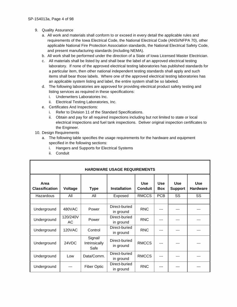
10. Design Requirements
a. The following table specifies the usage requirements for the hardware and equipment
specified in the following sections:
i. Hangers and Supports for Electrical Systems
ii. Conduit
HARDWARE USAGE REQUIREMENTS
Area Classification Voltage Type Installation
Use Conduit
Use Box
Use Support
Use Hardware
Hazardous All All Exposed RMCCS PCB SS SS
Underground 480VAC Power Direct-buried
in ground RNC --- --- ---
Underground 120/240V
AC Power
Direct-buried
in ground RNC --- --- ---
Underground 120VAC Control Direct-buried
in ground RNC --- --- ---
Underground 24VDC
Signal/
Intrinsically
Safe
Direct-buried
in ground RMCCS --- --- ---
Underground Low Data/Comm.Direct-buried
in ground RMCCS --- --- ---
Underground --- Fiber Optic Direct-buried
in ground RNC --- --- ---

SP-154013a, Page 5 of 98
HARDWARE USAGE REQUIREMENTS
Area Classification Voltage Type Installation
Use Conduit
Use Box
Use Support
Use Hardware
--- All All
Outdoor
Exposed RMCCS CB SS SS
NOTES:
1. All conduit in new structures shall be concealed.
2. No substitutions shall be allowed unless approved by engineer.
3. Transition to exposed conduit shall comply with specified requirements for exposed
conduit, regardless of whether transition is rigid or flexible.
4. Transition from underground or concrete encased conduit shall be RMCCS.
5. Sheet metal boxes are not acceptable for exposed installation.
6. Below grade locations shall be considered damp or wet locations.
ABBREVIATIONS:
RNC: Rigid Non-metallic Conduit RNB: Rigid Non-metallic
Box
RN: Rigid Non-Metallic
RMCS: Galvanized Rigid Metal
Conduit
CB: Cast Box GS: Galvanized Steel
RMCCS: PVC Coated Galvanized
Rigid Metal Conduit
PCB: PVC Coated Cast
Box
SS: Stainless Steel
EMT: Electrical Metallic Tubing SB: Steel Box
AL: Aluminum
B. MATERIALS.
1. Access Panels and Doors
a. Lay-in Ceilings:
i. Removable lay-in ceiling tiles in 2 foot by 2 foot or 2 foot by 4 foot configuration are
sufficient; no additional access provisions are required unless specifically indicated.
b. Drywall and Plaster Walls and Ceilings:
i. 16 gauge frame with not less than a 20 gauge hinged door panel, prime coated steel for
general applications, stainless steel for use in toilets, showers and similar wet areas,
concealed hinges, screwdriver operated cam latch for general application, key lock for
use in public areas, UL listed for use in fire rated partitions if required by the application.
Use the largest size access opening possible, consistent with the space and the
equipment needed service; minimum size is 12 inch by 12 inch.
2. Sealing and Fire-Stopping
i. Refer to Architectural requirements.
ii. Sealing and fire stopping of sleeves/openings between conduits, cable trays, wire ways,
troughs, cable bus, bus duct, etc. and the structural or partition opening shall be the

SP-154013a, Page 6 of 98
responsibility of the Contractor whose work penetrates the opening. Individuals skilled in
such work shall perform the sealing and fire stopping.
iii. Whenever possible, avoid penetrations of fire and smoke rated partitions. When they cannot
be avoided, verify that sufficient space is available for the penetration to be effectively fire
and smoke stopped.
iv. Manufacturers:
i. 3M, STI/SpecSeal, Tremco, or approved equal.
ii. The same manufacturer shall provide all fire stopping systems.
iii. The Contractor will be responsible for selecting the appropriate UL tested fire stop
system for each application required on the project.
v. Use a product that has a rating not less than the rating of the wall or floor being penetrated.
Reference architectural drawings for identification of fire and/or smoke rated walls and floors.
vi. Contractor shall use fire stop putty, caulk sealant, intumescent wrap strips, intumescent fire
stop collars, fire stop mortar or a combination of these products to provide a UL listed system
for each application required for this project. Provide mineral wool backing where specified
in manufacturer's application detail.
3. Non-Rated Penetrations
a. Conduit Penetrations Through Below Grade Walls:
iii. In exterior wall openings below grade, use a modular mechanical type seal consisting of
interlocking synthetic rubber links shaped to continuously fill the annular space between
the uninsulated conduit and the cored opening or a water-stop type wall sleeve.
b. Conduit and Cable Tray Penetrations:
i. At conduit and cable tray penetrations of non-rated interior partitions, floors and exterior
walls above grade, use urethane caulk in annular space between conduit and sleeve, or
the core drilled opening.
C. CONSTRUCTION. 1. Field Measurements
a. The Contractor shall obtain from the appropriate trades and review shop drawings for all
equipment requiring electrical connections.
b. Field verify all measurements. Do not base electrical installation or equipment locations on
the plans.
c. Identify conflicts with the work of other trades prior to installation of electrical system.
d. Electrical installation shall be based upon shop drawing requirements and field verified
measurements. Adjust electrical system installation to satisfy field requirements.
2. Delivery, Storage and Handling
a. Accept electrical equipment on site. Inspect for damage.
b. Protect electrical equipment from weather, corrosion, and entrance of debris.
3. Installation
a. Excavation And Backfill:
i. Perform all excavation and backfill work to accomplish indicated electrical systems
installation in accordance with other sections of this specification.
b. Concrete Work:
i. Coordinate the quantity and location of all cast-in-place concrete work with the
architectural drawings.
ii. All cast-in-place concrete will be performed by the Contractor unless noted otherwise.
Provide all layout drawings, anchor bolts, metal shapes, and/or templates required to be
cast into concrete or used to form concrete for the support of electrical equipment.
c. Cutting And Patching:

SP-154013a, Page 7 of 98
i. Cutting and patching shall be performed in accordance with the requirements for
architectural work. Refer to other sections of these specifications.
d. Building Access:
i. Arrange for the necessary openings in the building to allow for admittance of all
apparatus. When the building access was not previously arranged and must be provided
by this Contractor, restore any opening to its original condition after the apparatus has
been brought into the building.
e. Equipment Access:
i. Install all piping, conduit, ductwork, and accessories to permit access to equipment for
maintenance. Coordinate the exact location of wall and ceiling access panels and doors,
making sure that access is available for all equipment and specialties. Where access is
required in plaster or drywall walls or ceilings, furnish access doors and arrange for
installation with appropriate trades.
f. Working Clearances:
i. Minimum installed equipment working clearances as required by the NEC shall be
maintained.
ii. Minimum required dedicated electrical equipment space as required by the NEC shall be
maintained.
iii. Coordinate these requirements with the work of other trades.
iv. Identify conflicts with working space requirements prior to installation of equipment.
g. Coordination:
i. Cooperate with other trades in locating work in a proper manner. Should it be necessary
to raise or lower or move longitudinally any part of the electrical work to better fit the
general installation, such work shall be done at no extra cost to the Contracting Authority.
The Contractor shall check location of electrical outlets with respect to other installations
before installing.
ii. Verify that all devices are compatible for the surfaces on which they will be used. This
includes, but is not limited to, light fixtures, panel boards, devices, etc. and recessed or
semi-recessed heating units installed in/on architectural surfaces.
iii. Coordinate all work prior to installation. Any installed work that is not coordinated and
that interferes with the work of another trade shall be removed or relocated at no
additional cost to the Contracting Authority.
iv. Verify the integrity of fire or smoke ratings where penetrations are required.
h. Sleeves:
i. Process Equipment Areas:
New poured concrete construction: cast in place, Schedule 40, PVC sleeve.
All other construction: core drill sleeve openings large enough to insert Schedule 40
PVC sleeve and grout around the sleeve.
Floor penetrations:
Extend top of sleeve 2 inches above the floor.
Where installation of sleeve in floor is not practical, provide 2 inch deep
housekeeping pad extending 3 inches around cast in place conduits.
ii. Non-Process Equipment Areas:
Hollow walls: Schedule 40, PVC sleeves, grout around sleeve in masonry
construction.
All other Areas: core drill sleeve openings large enough to insert Schedule 40 PVC
sleeve and utilize the core drilled opening as the sleeve.
iii. Conduit Support:

SP-154013a, Page 8 of 98
If the pipe penetrating the sleeve is supported by a pipe clamp resting on the sleeve,
weld a collar or struts to the sleeve that will transfer weight to the floor structure.
i. Sealing And Firestopping:
i. Fire and/or Smoke Penetrations:
Install approved product in accordance with the manufacturer's instructions where a
pipe (i.e. cable tray, bus, cable bus, conduit, wire way, trough, etc.) penetrates a fire
rated surface.
Where fire stop mortar is used to infill large fire-rated floor openings that could be
required to support weight, provide permanent structural forming. Fire stop mortar
alone is not adequate to support any substantial weight.
ii. Non-Rated Surfaces:
When the opening is through a non-fire rated wall, floor, ceiling or roof the opening
must be sealed using an approved type of material.
Install escutcheons or floor/ceiling plates where conduit, penetrates non-fire rated
surfaces in occupied spaces. Occupied spaces for this paragraph include only those
rooms with finished ceilings and the penetration occurs below the ceiling.
In exterior wall openings below grade, assemble rubber links of mechanical seal to
the proper size for the conduit and tighten in place, in accordance with the
manufacturer's instructions.
At interior partitions, conduit penetrations are required to be sealed for all areas .
Apply sealant to both sides of the penetration in such a manner that the annular
space between the conduit sleeve and the conduit is completely filled.
j. Housekeeping and Clean-up
i. On a daily basis, clean up and remove all debris and rubbish resulting from work and
repair all damage to new and existing equipment resulting from work.
ii. Remove all tools, excess material, and unused equipment from the site when job is
complete.
k. General Inspection and Cleaning of Electrical Equipment
i. Inspect for physical damage and abnormal mechanical or electrical conditions.
ii. Any item found to be out of tolerance, or in any other way defective as a result of the
required testing, shall be reported to the Engineer. Procedure for repair and/or
replacement will be outlined. After appropriate corrective action is completed the item
shall be re-tested.
iii. Compare equipment nameplate information with the plans and report any discrepancies.
iv. Verify proper auxiliary device operation and indicators.
v. Check tightness of accessible bolted electrical joints. Use torque wrench method.
vi. Make a close examination of equipment and remove any shipping brackets, insulation,
packing, etc. that may not have been removed during original installation.
vii. Make a close examination of equipment and remove any dirt or other forms of debris that
may have collected in existing equipment or in new equipment during installation.
viii. Vacuum inside of panelboards, switchboards, switchgear, transformer core and coils,
horizontal and vertical busducts, MCC's, control panels, and any other similar equipment
ix. Clean All Equipment:
Loosen attached particles and vacuum them away.
Remove any remaining packing material adhesives with suitable cleaning solution.
Touch-up factory applied finishes damaged during installation using manufacturer
approved means to match original finish.

SP-154013a, Page 9 of 98
4. Testing and Start-Up Services
a. Refer to the requirements the individual technical sections.
5. Training
a. Refer to the requirements the individual technical sections.
154013a.03 UTILITY SERVICES
A. DESCRIPTION. Provide and install complete and operable utility services as required on the drawings and as specified
herein.
1. Summary
a. Arrange with the Electric Utility for permanent and temporary electric service. i. Electric Service:
Utility Company: .
Mid-American Energy
Phone number: 800-329-6261.
System Characteristics:
Facility type: Storm Water Lift Station.
Required service voltage: 277/480V 3-phase, 4-wire.
Required service size: 100A.
2. Applicable Publications
a. The following publications of the issues listed below, but referred to thereafter by basic
designation only, form a part of this specification to the extent indicated by the reference
thereto.
i. American National Standards Institute/National Fire Protection Agency (ANSI/NFPA),
Specifications and Standards
ii. ANSI/NFPA 70 - National Electrical Code (NEC) and state amendments thereto, Current
Edition.
iii. National Electrical Contractors Association (NECA), Standard of Installation, Current
Edition.
iv. National Electrical Manufacturers Association (NEMA), Specifications and Standards,
current edition.
v. Underwriters Laboratories, Inc. (UL), Specifications and Standards, current edition.
3. Related Work Elsewhere
a. The following divisions may include work which is related to utility services, but which is not
included under the scope of this section:
i. Heating, Ventilating, and Air Conditioning (HVAC)
ii. Process Integration
iii. Material Processing and Handling Equipment.
iv. Process Heating, Cooling, and Drying Equipment.
v. Industry-specific Manufacturing Equipment.
vi. Electrical Power Generation.
4. Shop Drawings
a. Submit shop drawings in accordance with the requirements of Division 11 of the Standard
Specifications.
b. The following information shall be submitted specifically for utility services:
i. Manufacturer literature sufficient in scope to demonstrate compliance with the
requirements of this specification.
ii. Documentation required by utility company for approval.

SP-154013a, Page 10 of 98
5. Quality Assurance
a. Service entrance and metering equipment provided under this section shall be UL Listed for
the service intended and shall be approved by the utility company.
B. CONSTRUCTION. 1. Division of Work
a. The Contractor shall be responsible for coordinating conductor marking and color coding
requirements with control system equipment supplier(s).
2. Field Measurements a. Verify existing conditions and dimensions.
b. Verify that service equipment is ready to be connected and energized.
c. Make arrangements with utility company and obtain required inspections before energizing
service(s).
d. Coordinate location of utility company facilities to ensure proper access is available.
3. Installation
a. Install service entrance conduit and conductors in accordance with utility company
instructions.
b. Install metering equipment in accordance with utility company instructions.
154013a.04 LOW-VOLTAGE ELECTRICAL POWER CONDUCTORS AND CABLES
A. DESCRIPTION. Furnish and install complete and operable wire and cable systems as indicated on the drawings and as
specified herein. 1. Applicable Publications
a. The following publications of the issues listed below, but referred to thereafter by basic
designation only, form a part of this specification to the extent applicable.
i. American National Standards Institute/National Fire Protection Agency (ANSI/NFPA),
Specifications and Standards, current edition:
NFPA 70 - National Electrical Code.
ii. ASTM International, originally known as the American Society for Testing and Materials,
Specifications and Standards, current edition:
ASTM B800-05 Standard Specification for 8000 Series Aluminum Alloy Wire for
Electrical Purposes-Annealed and Intermediate Tempers
ASTM B801-99 Standard Specification for Concentric-Lay-Stranded Conductors of
8000 Series Aluminum Alloy for Subsequent Covering or Insulation
iii. National Electrical Contractors Association (NECA), current edition.
NECA 1 - Standard Practices for Good Workmanship in Electrical Contracting.
iv. Underwriters Laboratories, Inc. (UL), Specifications and Standards, current edition.
U.L. 44 - Rubber-Insulated Wires and Cables.
U.L. 50 - Enclosures for Electrical Equipment.
U.L. 83 - Thermoplastic-Insulated Wires.
U.L. 514B - Conduit, Tubing, and Cable Fittings.
U.L. 758 - 220° F Appliance Wiring Materials.
U.L. 854 - Service Entrance Cables.
U.L. 1063 - Machine-Tool Wires and Cables.

SP-154013a, Page 11 of 98
U.L. 1277 - Type TC Power and Control Tray Cables.
U.L. 1569 - Metal-Clad Cables
UL 1581 - Vertical Tray.
2. Submittals
a. The following information shall be submitted specifically for wire and cable:
i. Literature sufficient in scope to demonstrate compliance with the requirements of this
specification.
ii. Clearly identify the types of wire and cable proposed.
3. Quality Assurance
a. Products: Listed and classified by UL or testing firm acceptable to the authority having
jurisdiction as suitable for the purpose specified and indicated.
b. Wire and cable manufacturers shall be certified to ISO 9001 International Quality Standard
and shall have third party certification verifying quality assurance in design/development and
production in accordance with ISO 9001.
B. MATERIALS. 1. Wire and Cable – General Purpose (600V, Copper)
a. Manufacturer: Contractor option.
b. General:
i. THWN/THHN general purpose building wire insulated with polyvinyl chloride (PVC) and
covered with protective sheath of nylon intended for lighting and power circuits at 600
volts or less, in residential, commercial and industrial buildings.
ii. The wire shall be suitable for 195°F maximum continuous conductor temperature in dry
locations and 170°F in wet locations and listed by Underwriters Laboratories for use in
accordance with the National Electrical Code.
c. Conductors:
i. Class B or Class C stranded, annealed uncoated copper per UL Standard 83 or 1063.
d. Insulation:
i. Each conductor shall be insulated with PVC and sheathed with nylon complying with the
requirements of UL Standard 83 for Types THHN/THWN and UL Standard 1063 for Type
MTW and CSA C22.2 No. 75 for T90 Nylon.
ii. Types THWN/THHN shall comply with the optional Gasoline and Oil Resistant rating of
UL Standard 83. The insulation shall also comply with UL requirements for 220°F
Appliance Wiring Material.
iii. The average thickness of PVC insulation, for a given conductor size, shall be as specified
in UL Standard 83 for Types THWN or THHN. The minimum thickness at any point, of the
PVC insulation, shall be not less than 90% of the specified average thickness.
iv. The minimum thickness at any point of the nylon sheath shall be as specified in UL
Standard 83 for Types THWN or THHN.
v. The PVC insulation shall be applied tightly to the conductor and shall be free-stripping.
e. Identification:
i. The wire shall be identified by surface marking indicating manufacturer's identification,
conductor size and metal, voltage rating, UL Symbol, type designations and optional
ratings. The wire shall also be identified as C(UL) Type T90 Nylon or TWN75, FT1.
f. Tests:
i. Wire shall be tested in accordance with the requirements of UL Standard 83 for Types
THWN or THHN wire and for the optional Gasoline and Oil Resistant listings; as Type
MTW to UL Standard 1063 (stranded items); as AWM to UL Standard 758 (stranded
items); and as C(UL) Type T90 Nylon or TWN75.

SP-154013a, Page 12 of 98
vii. Usage:
i. General use power wiring, minimum size No.12 AWG.
ii. General use control wiring, minimum size No.14 AWG.
2. Shielded Power Cable (600V)
a. Manufacturer
i. Contractor option.
ii. General:
i. Three conductor type TC Tray Cable insulated with cross linked polyethylene and PVC
jacket overall, for use on circuits rated 600 volts and 195°F maximum continuous
conductor temperature in wet or dry locations.
ii. Cables approved for installation in cable trays in accordance with the NEC and for
installation in air, in ducts or conduits, in tray or trough, in open wiring or direct buried.
iii. Conductors:
i. Shall be Class B stranded uncoated soft copper.
ii. Suitable separator over the conductor may be used at the option of the manufacturer.
iii. Three phase conductors shall be cabled together with a Class B stranded, uncoated
copper grounding conductor and suitable non-hygroscopic fillers to make round.
iv. Length of lay shall not exceed 35 times the phase conductor diameter.
v. The grounding conductor shall comply with the requirements of UL Standard 1277.
vi. The cable assembly shall be covered with a copper tape shield with drain wire, applied
with a 10% minimum lap.
iv. Insulation:
i. Each phase conductor shall be insulated with chemically cross linked polyethylene,
meeting Type XHHW-2 requirements of Underwriters Laboratories.
ii. The average thickness of insulation shall be as specified in UL Standard 44 for Type
XHHW-2 conductors. The minimum thickness at any point shall be not less than 90% of
the specified average thickness.
iii. The insulated phase conductors shall be black in color and shall be printed with the
numerals "1", "2", and "3" on their surface.
iv. Each cable shall have a PVC protective jacket applied over the taped assembly. The
jacket shall meet the Sunlight Resistant requirements of UL Standard 1277.
v. The average jacket thickness shall be in accordance with UL Standard 1277. The
minimum thickness at any point shall be not less than 80% of the specified average
thickness.
v. Identification:
i. Cables shall be identified by means of surface ink printing indicating manufacturer,
number of conductors, size, voltage rating, and required UL information.
vi. Tests:
i. Individual conductors and completed cables shall be tested in accordance with UL
requirements for Type TC Power Control Tray Cables having XHHW-2 conductors.
ii. Cables shall be capable of passing the ribbon burner cable tray flame test requirements
of UL and IEEE.
vii. Usage:
i. Power wiring for motor loads controlled by adjustable frequency drives, where so
indicated on the drawings.
3. Shielded Instrumentation Cable (300V)
a. Manufacturer: Contractor option.
b. General:

SP-154013a, Page 13 of 98
i. Power limited tray cable - two conductor, No.16 AWG (7x24) bare copper, PVC
insulation, overall shield with No.18 AWG (7x26) tinned copper drain wire, PVC
jacket with nylon ripcord.
c. Electrical Characteristics:
i. Max. Operating voltage: 300Vrms
ii. Conductor DC resistance at 70°F: 3.7 ohms per 1000 feet
iii. Shield DC resistance at 70°F: 5.1 ohms per 1000 feet
iv. Capacitance between conductors at 1 kHz: 61 picofarads per foot
v. Capacitance between conductor and shield at 1 kHz: 114 picofarads per foot
vi. Inductance: 0.19 microhenries per foot
d. Physical Characteristics:
i. Temperature rating: -20°F to 220°F
ii. Insulation material: PVC
iii. Average insulation thickness: 0.016 inches
iv. Jacket material: Sun resistant PVC.
v. Jacket thickness: 0.037 inches nominal
vi. Shield: Aluminum/Polyester, 100% coverage.
vii. Overall lay length: 2 inches (6 twists per foot)
viii. Maximum pulling tension: 94 pounds
ix. Minimum bend radius: 2.6 inches
x. Flame resistance: UL 1581 vertical tray.
e. Usage:
i. Instrumentation cable.
C. CONSTRUCTION. 1. Field Measurements
a. Field verify all measurements. Do not base electrical installation or equipment locations on
the plans.
b. Identify conflicts with the work of other trades prior to installation of electrical system.
c. Adjust electrical system installation to satisfy field requirements.
2. Delivery, Storage and Handling
a. Accept electrical equipment on site. Inspect for damage.
b. Protect electrical equipment from weather, corrosion, and entrance of debris.
3. Installation
a. Pre-Installation:
i. Verify that interior of building has been protected from weather.
ii. Verify that mechanical work likely to damage wire has been completed.
iii. Completely and thoroughly swab raceway prior to installation.
iv. Verify that field measurements are as shown on drawings.
v. Wire and cable routing shown on drawings is approximate unless dimensioned. Route
wire and cable to satisfy project conditions.
vi. Where wire and cable routing is not shown, and destination only is indicated, determine
exact routing and lengths required.
vii. Determine required separation between cable and other work.
viii. Determine cable routing to avoid interference with other work.
ix. Any single conduit or raceway utilized for a feeder circuit shall contain only power
conductors of a single feeder circuit. Do not combine feeder circuits without engineer's
written approval.

SP-154013a, Page 14 of 98
x. Plans indicate individual homerun equipment connections. Contractor may combine
branch circuits of common types in single conduits provided the following conditions are
met:
NEC requirements for conductor de-rating are satisfied.
Conduit fill does not exceed thirty percent. Ten percent fill shall be reserved for
future use.
xi. No more than eight 24VDC analog circuits may be combined in a single conduit unless
specifically stated otherwise on the drawings.
b. Conductor Sizing:
i. Conductor sizes are based on copper unless otherwise noted.
ii. Use conductor not smaller than No.12 AWG for power and lighting circuits.
iii. Use No.10 AWG conductors for 20 ampere, 120 volt branch circuits longer than 75 feet.
iv. Where circuit wiring length exceeds length identified on the feeder schedule, increase
wire size as needed to maintain a maximum voltage drop of three percent.
v. Use conductor not smaller than No.14 AWG for control circuits.
vi. Unless shown otherwise on the plans, power wiring shall be No. 12 AWG.
c. Wire Pulling:
i. Pull all conductors into raceway at same time.
ii. No. 4 AWG and larger wire and power cables shall lubricated with pulling lubricant to
reduce pulling tension and abrasion damage. The lubricant shall be water or wax based
containing no oils or greases that may adversely affect cable jackets.
iii. The minimum bend radius and maximum pulling tension ratings of the wire and cable
shall not be exceeded.
d. Splices and Terminations:
i. Splices and terminations shall not be made within raceways.
ii. Clean conductor surfaces before splicing or terminating.
iii. Make splices, taps, and terminations to carry full amp capacity of conductors with no
perceptible temperature rise.
iv. Insulated spring wire connectors may be used to splice 120V power circuits.
v. Control, communication, and data transmission wire and cable shall not be spliced.
vi. Use split bolt connectors for copper conductor splices and taps, No. 6 AWG and larger.
Tape uninsulated conductors and connector with electrical tape to 150% of insulation
rating of conductor.
vii. Use solderless pressure connectors with insulating covers for copper conductor splices
and taps, No. 8 AWG and smaller.
viii. Use insulated spring wire connectors with plastic caps for copper conductor splices and
taps, No. 10 AWG and smaller.
e. Motors:
i. Motor wiring to motors less than 10 horsepower shall be spliced and terminated with fully
insulated crimp-on end cap with a layer of self-vulcanizing rubber tape, followed by five
layers of vinyl electrical tape. “SkotchLocks” and similar devices shall not be used.
ii. Motor wiring to motors 10 horsepower or larger shall be spliced and terminated with
crimp-on ring terminal lugs, brass nuts, bolts and washers with a layer of self-vulcanizing
rubber tape, followed by five layers of vinyl electrical tape. “SkotchLocks” and similar
devices shall not be used.
f. Unshielded power cables:
i. Unshielded power cables shall be spliced and terminated with crimp-on ring terminal
lugs, brass nuts, bolts and washers with a layer of self-vulcanizing rubber tape, followed

SP-154013a, Page 15 of 98
by five layers of vinyl electrical tape. “SkotchLocks” and similar devices shall not be
used.
4. Testing and Start-Up Services
a. Inspect wire for physical damage and proper connection.
b. Measure tightness of bolted connections and compare torque measurements with
manufacturer's recommended values.
c. Verify continuity of each conductor.
d. Feeder or branch circuits with ampacity greater than 100 amperes shall be tested after
installation to measure insulation resistance of each conductor.
e. All equipment shall be disconnected and the wire ends shall be cleaned and dried.
f. Connect Megohmeter between conductor and a grounded point in the enclosure and
energize until the reading stabilizes.
154013a.05 GROUNDING AND BONDING FOR ELECTRICAL SYSTEMS
A. DESCRIPTION. Furnish and install complete and operable grounding and bonding systems as indicated on the drawings
and as specified herein. 1. Applicable Publications
a. The following publications of the issues listed below, but referred to thereafter by basic
designation only, form a part of this specification to the extent applicable.
i. American National Standards Institute/National Fire Protection Agency (ANSI/NFPA),
Specifications and Standards, current edition:
NFPA 70 - National Electrical Code.
ANSI/NFPA 99 - Health Care Facilities.
ii. National Electrical Contractors Association (NECA), current edition.
NECA 1 - Standard Practices for Good Workmanship in Electrical Contracting.
iii. National Electrical Manufacturers Association (NEMA), Specifications and Standards,
Current Edition.
iv. Underwriters Laboratories, Inc. (UL), Specifications and Standards, Current Edition.
v. Institute of Electrical and Electronics Engineers (IEEE), Specifications and Standards,
current edition:
IEEE 837 - Standard for Qualifying Permanent Connections Used in Substation
Grounding.
2. Quality Assurance
a. Measure ground resistance from system neutral connection at service entrance to convenient ground reference point using suitable ground testing equipment. Resistance shall not exceed 2 ohms. Additional grounding electrodes shall be used to satisfy ground resistance requirements where required by earth conditions.
B. MATERIALS.
1. Rod Electrode
a. Material: Copper-clad steel.
b. Diameter: 3/4-inch minimum.
c. Length: 10-feet minimum. Rod shall be driven at least 9.5-feet deep.
d. Use one or more ground rods to obtain the minimum specified ground resistance. This
applies to manholes, padmount switches, transformers, service entrances, and all other
equipment requiring a supplemental grounding electrode. Minimum of three ground rods
shall be used to ground the service entrance as indicated on plans.

SP-154013a, Page 16 of 98
2. Mechanical Connectors
a. The mechanical connector bodies shall be manufactured from high strength, high conductivity
cast copper alloy material. Bolts, nuts, washers and lockwashers shall be made of silicon
bronze and supplied as a part of the connector body and shall be of the two bolt type.
b. Split bolt connector types are not allowed.
c. The connectors shall meet or exceed UL 467 and be clearly marked with the catalog number,
conductor size and manufacturer.
d. Grounding access wells shall be provided for access to underground mechanical grounding
connections. Access well shall be ANSI Tier rated for the area in which it is installed.
3. Compression Connectors
a. The compression connectors shall be manufactured from pure wrought copper. The
conductivity of this material shall be no less than 99%.
b. The connectors shall meet or exceed the performance requirements of IEEE 837, latest
revision.
c. The installation of the connectors shall be made with a compression, tool and die system, as
recommended by the manufacturer of the connectors.
d. The connectors shall be clearly marked with the manufacturer, catalog number, conductor
size and the required compression tool settings.
e. Each connector shall be factory filled with an oxide-inhibiting compound.
4. Exothermic Connections
a. Select the appropriate kit for specific types, sizes, and combinations of conductors and other
items to be connected. Field personnel shall be trained in execution of welds.
5. Wire
a. Material: Stranded copper (aluminum not permitted).
b. Grounding Electrode Conductor: Size as shown on drawings, specifications or as required by
NFPA 70, whichever is larger.
c. Manhole and Vault Bonding: No. 4/0 minimum.
d. Feeder and Branch Circuit Equipment Ground: Size as shown on drawings, specifications or
as required by NFPA 70, whichever is larger. Differentiate between the normal ground and
the isolated ground when both are used on the same facility.
C. CONSTRUCTION. 1. Field Measurements
a. Field verify all measurements. Do not base electrical installation or equipment locations on
the plans.
b. Identify conflicts with the work of other trades prior to installation of electrical system.
c. Adjust electrical system installation to satisfy field requirements.
2. Installation
a. General:
i. Verify that final backfill and compaction has been completed before driving rod
electrodes.
ii. Install products in accordance with manufacturer instructions.
iii. Mechanical connections shall be accessible for inspection and checking. No insulation
shall be installed over mechanical ground connections.
iv. Ground connection surfaces shall be cleaned and all connections shall be made so that it
is impossible to move them.
v. Attach grounds permanently before permanent building service is energized.

SP-154013a, Page 17 of 98
vi. Install rod electrodes at locations indicated or as required by local code, whichever
requires the most rods. Install additional rod electrodes as required to achieve specified
resistance to ground.
vii. Connect grounding electrode conductor and reinforcing steel in foundation footing. Bond
steel together.
viii. Bond all conductive components to meet Regulatory Requirements.
ix. Bond together metal siding not attached to grounded structure; bond to ground.
x. All separate ground wires shall be enclosed in rigid galvanized steel conduit and bonded
at both ends to the rigid galvanized steel conduit with an approved fitting.
b. Less than 600 volt system grounding:
i. Supplementary Grounding Electrode: Use driven ground rod on exterior of building.
ii. Copper grounding electrode conductor shall be sized as indicated or as required by NEC,
whichever is larger and shall be extended from secondary service system neutral to
street side of water meter, building steel, ground rod, and any concrete encased
electrodes. Bonding jumper shall be installed around water meter. Install conductor in
separate rigid conduit. Bond conduit as described above.
iii. Receptacle Grounding: All receptacles installed shall have a separate grounding contact.
iv. Bond together system neutrals, service equipment enclosures, exposed non-current
carrying metal parts of electrical equipment, metal raceway systems, grounding
conductor in raceways and cables, receptacle ground connectors, and plumbing systems.
v. Bond together each metallic raceway, pipe, duct and other metal objects.
vi. Equipment Grounding Conductor: Separate, insulated green conductor shall be installed
within each raceway and cable tray, sized per NEC or as indicated in the contract
documents whichever is larger. Terminate each end on suitable lug, bus, enclosure or
bushing, per NEC. Install a ground wire from each device to the respective enclosure.
3. Testing and Start-Up Services
a. Inspect grounding and bonding system conductors and connections for tightness and proper
installation.
154013a.06 HANGERS AND SUPPORTS FOR ELECTRICAL SYSTEMS
A. DESCRIPTION. Furnish and install supporting devices as indicated on the drawings, scheduled in Common Work Results
for Electrical, and as specified herein. 1. Applicable Publications
a. The following publications of the issues listed below, but referred to thereafter by basic
designation only, form a part of this specification to the extent applicable.
i. American Iron and Steel Institute (AISI), Specifications and Standards, current edition.
ii. American National Standards Institute/National Fire Protection Agency (ANSI/NFPA),
Specifications and Standards, current edition:
NFPA 70 - National Electrical Code.
iii. American Society for Testing and Materials (ASTM), Specifications and Standards,
current edition:
ASTM A653 - General Requirements for Steel Sheet, Zinc-Coated Galvanized by the
Hot-Dip Process.
ASTM A1011 - Specification for Steel Sheet and Strip, Hot-Rolled, Carbon,
Structural, High-Strength Low-Ally and High-Strength Low Alloy with Improved
Formability (Formerly ASTM A570).

SP-154013a, Page 18 of 98
ASTM F1136 - Standard Specification for Chromium/Zinc Corrosion Protective
Coatings for Fasteners.
ASTM A907 - Standard Specification for Steel, Sheet, and Strip, Heavy-Thickness
Coils, Carbon, Hot-Rolled, Structural Quality.
ASTM B633 - Specification for Electrodeposited Coatings of Zinc on Iron and Steel.
iv. National Electrical Contractors Association (NECA), current edition.
NECA 1 - Standard Practices for Good Workmanship in Electrical Contracting.
NECA 101 - Standard for Installing Steel Conduit (Rigid, IMC, EMT).
v. Metal Framing Manufacturers Association (MFMA), Specifications and Standards, current
edition.
2. Submittals
a. The following information shall be submitted specifically for supporting devices:
i. Submit outline drawings and dimensions for equipment support racks.
3. Quality Assurance
a. Bolted framing channels and fittings shall have the manufacturers name, part number, and
material heat code identification number stamped in the part itself for identification. Material
certification sheets and test reports must be made available by the manufacturer upon
request
b. Stainless steel bolted framing parts shall be stamped to identify the material. Material
certification sheets and test reports must be made available by the manufacturer upon
request.
B. MATERIALS. 1. Strut, Channels, and Connectors
a. Manufacturers:
i. Cooper B-Line, Inc.
ii. Unistrut
iii. Supertrut
iv. Or equal
b. General:
i. Strut shall be 1 5/8 inches wide in varying heights and welded combinations as required
to meet load capacities and designs indicated on the drawings.
c. Materials and Finish:
i. Aluminum: Strut shall be manufactured of extruded aluminum alloy 6063-T6. All fittings
and hardware shall be zinc plated according to ASTM B633 (SC3 for fittings, SC1 for
threaded hardware) for indoor use only. For outdoor use, all fittings and hardware shall
be stainless steel Type 304.
ii. Hot-dip Galvanized Steel: Strut shall be made from steel meeting the minimum
mechanical properties of ASTM A1011 SS, Grade 33 and shall be hot-dip galvanized
after fabrication in accordance with ASTM A123. Fittings shall be manufactured from
steel meeting the minimum requirements of ASTM A907 SS, Grade 33, and hot-dip
galvanized after fabrication in accordance with ASTM A123. All hardware shall be
stainless steel Type 304 or chromium zinc ASTM F1136 Gr. 3. All hot-dip galvanized
after fabrication products must be returned to point of manufacture after coating for
inspection and removal of all sharp burrs.
iii. Stainless Steel: All strut, fittings and hardware shall be made of AISI Type 304 stainless
steel.

SP-154013a, Page 19 of 98
2. Anchors and Fasteners
i. Concrete and Structural Elements: Use stainless steel precast insert system, expansion
anchors and preset inserts.
ii. Steel Structural Elements: Use stainless steel beam clamps.
iii. Concrete Surfaces: Use stainless steel self-drilling anchors and expansion anchors.
iv. Hollow Masonry, Plaster, and Gypsum Board Partitions: Use toggle bolts or hollow wall
fasteners.
v. Solid Masonry Walls: Use stainless steel expansion anchors and preset inserts.
vi. Sheet Metal: Use stainless steel sheet metal screws.
vii. Wood: Use stainless steel wood screws.
viii. All other fasteners: stainless steel screws, suitable for the required usage.
3. Hardware
a. Conduit and equipment supports, clamps, and other miscellaneous materials shall be
constructed of the following materials as scheduled in Common Work Results for Electrical.
i. Steel.
ii. Zinc plated steel.
iii. Galvanized, malleable iron.
iv. PVC coated, galvanized, malleable iron.
v. Stainless steel.
vi. PVC.
C. CONSTRUCTION.
1. Field Measurements
a. Field verify all measurements. Do not base locations and dimensions on the plans.
b. Identify conflicts with the work of other trades prior to installation of electrical equipment.
c. Adjust equipment support rack installation to satisfy field requirements.
2. Delivery, Storage, and Handling
a. Accept supporting devices on site. Inspect for damage.
b. Protect supporting devices from corrosion and damage. Do not install damaged materials.
3. Installation
a. General:
i. Furnish and install supports and fasteners for all electrical components required for the
project, including free standing supports required for those items remotely mounted from
the building structure, catwalks, walkways etc.
ii. Thoroughly clean and remove construction debris from installation.
b. Strut Channel:
i. Install strut in accordance with MFMA-102 "Guidelines for the Use of Metal Framing"; in
accordance with equipment manufacturer's recommendations, and with recognized
industry practices.
ii. Fabricate supports from channel. Rigidly weld members or use hexagon head bolts to
present a neat appearance with adequate strength and rigidity. Use spring lock washers
under all nuts.
iii. File and de-bur cut ends of galvanized support channel and spray paint with cold
galvanized paint to prevent rusting.
iv. Bridge studs top and bottom with channels to support flush-mounted cabinets and
panelboards in stud walls.
c. Anchors and Fasteners:
i. Provide anchors, fasteners, and supports in accordance with NECA "Standard Practices
for Good Workmanship in Electrical Contracting".

SP-154013a, Page 20 of 98
ii. Do not fasten supports to piping, ductwork, mechanical equipment, cable tray or conduit.
iii. Do not use spring steel clips and anchors.
iv. Do not use powder-actuated anchors.
v. Obtain permission from Engineer before drilling or cutting structural members.
vi. Install surface-mounted cabinets and panelboards with minimum of four anchors.
vii. Use channel supports to stand cabinets and panelboards 1-5/8-inch off interior or exterior
surfaces of exterior walls.
viii. Fasten hanger rods, conduit clamps, and outlet and junction boxes to building structure
using anchors and fasteners.
ix. Install free-standing electrical equipment on 3-inch concrete pads unless indicated
otherwise on the drawings.
x. Use threaded rod, minimum size 3/8 inch, for supports where indicated on the drawings.
xi. Install products in accordance with manufacturer instructions.
154013a.07 CONDUIT
A. DESCRIPTION. Furnish and install complete and operable conduit system as indicated on the drawings, scheduled in
Common Work Results for Electrical and as specified herein. 1. Applicable Publications
a. The following publications of the issues listed below, but referred to thereafter by basic
designation only, form a part of this specification to the extent applicable.
i. American National Standards Institute/National Fire Protection Agency (ANSI/NFPA),
Specifications and Standards, current edition:
ANSI C80.1 - Electrical Rigid Steel Conduit (ERSC).
ANSI C80.3 - Steel Electrical Metallic Tubing (EMT).
ANSI C80.5 - Electrical Rigid Aluminum Conduit (ERAC).
NFPA 70 - National Electrical Code.
ii. American Society for Testing and Materials (ASTM), Specifications and Standards,
current edition:
ASTM F2160 - Solid Wall High Density Polyethylene (HDPE) Conduit Based on
Controlled Outside Diameter.
ASTM D2239 - Polyethylene (PE) Plastic Pipe (SIDR) Based on Controlled Inside
Diameter.
ASTM D3035 - Polyethylene (PE) Plastic Pipe (SDR) Based on Controlled Outside
Diameter.
ASTM D3350 - Polyethylene Plastics Pipe and Fittings Materials.
iii. National Electrical Contractors Association (NECA), current edition.
NECA 1 - Standard Practices for Good Workmanship in Electrical Contracting.
NECA 101 - Standard for Installing Steel Conduit (Rigid, IMC, EMT).
iv. National Electrical Manufacturers Association (NEMA), Specifications and Standards,
current edition.
NEMA FB 1 - Fittings, Cast Metal Boxes, and Conduit Bodies for Conduit, Electrical
Metallic Tubing, and Cable; National Electrical Manufacturers Association.
NEMA RN 1 - Polyvinyl Chloride (PVC) Externally Coated Galvanized Rigid Steel
Conduit and Intermediate Metal Conduit; National Electrical Manufacturers
Association.

SP-154013a, Page 21 of 98
NEMA TC 2 - Electrical Polyvinyl Chloride (PVC) Tubing and Conduit; National
Electrical Manufacturers Association.
NEMA TC 3 - PVC Fittings for Use with Rigid PVC Conduit and Tubing; National
Electrical Manufacturers Association.
NEMA TC 7 - Smooth Wall Coilable Polyethylene Electrical Plastic Conduit.
v. Underwriters Laboratories, Inc. (UL), Specifications and Standards, current edition.
UL 1 - Standard for Flexible Metal Conduit
UL 6 - Electrical Rigid Metal Conduit - Steel.
UL 6A - Standard for Electrical Rigid Metal Conduit - Aluminum and Stainless Steel.
UL 651A Type EB and A Rigid PVC Conduit and HDPE conduit.
UL 651B Continuous Length HDPE.
UL 1660 - Liquid-Tight Flexible Nonmetallic Conduit.
UL 2239 - Standard for Safety for Hardware for the Support of Conduit, Tubing, and
Cable.
2. Submittals
a. Submit the following information specifically for conduit:
i. Manufacturer literature sufficient in scope to demonstrate compliance with the
requirements of this specification.
ii. Clearly identify the types of conduit and fittings proposed.
2. Quality Assurance
a. Products: Listed and classified by UL or testing firm acceptable to the authority having
jurisdiction as suitable for the purpose specified and indicated.
B. MATERIALS.
1. Galvanized Rigid Metal Conduit (Type RMCS)
a. Manufacturer: Contractor option.
b. Conduit:
i. Impact and crush resistant mild steel tube with an accurate circular cross section, a
uniform wall thickness, a defect free interior surface, and a continuous welded seam.
ii. Interior and exterior surfaces thoroughly and evenly coated with zinc using the hot-dip
galvanizing process.
iii. Top-coated with a compatible organic layer to inhibit white rust and increase corrosion
resistance.
iv. Factory cut threads, 0.75 inch taper per foot, protected after cutting with an application of
molten zinc.
c. Conduit Bodies:
i. Ferrous metal construction electro-galvanized inside and out and coated with aluminum
acrylic paint.
ii. Tapered, threaded hubs with integral bushing.
iii. Stainless steel hardware.
iv. Cover constructed of same material with solid gasket.
d. Fittings:
i. Ferrous metal construction electro-galvanized inside and out.
ii. Components critical to performance such as set screws, split rings, and locknuts
constructed of hardened steel or adequately designed to insure positive bonds.
2. PVC Galvanized Rigid Metal Conduit (Type RMCCS)
a. Manufacturer:
i. Perma-Cote Industries.

SP-154013a, Page 22 of 98
ii. Robroy.
iii. Ocal
iv. Plasti-Bond
v. Or equal.
b. General:
i. Conduit shall be UL Listed and the coating shall have been investigated by UL as
providing the primary corrosion protection for the rigid metal conduit.
ii. Independent certified test results shall be available to confirm coating adhesion under the
following conditions:
iii. Conduit immersed in boiling water with a minimum mean time to adhesion failure of 200
hours.
iv. Conduit and condulet exposure to 150°F and 95% relative humidity with a minimum
mean time to failure of 30 days.
v. No trace of internal coating shall be visible on a white cloth following six wipes over the
coating that has been wetted with acetone.
vi. The exterior coating bond shall be confirmed using the methods described in Section 3.8,
NEMA RN1. After these tests the physical properties of the exterior coating shall exceed
the minimum requirements specified in Table 3.1, NEMA RN1.
c. Conduit:
i. Impact and crush resistant mild steel tube with an accurate circular cross section, a
uniform wall thickness, and a defect free interior surface, and a continuous welded seam.
ii. Interior and exterior surfaces thoroughly and evenly coated with zinc using the hot-dip
galvanizing process.
iii. Factory cut threads, 0.75 inch taper per foot, protected after cutting with an application of
molten zinc.
iv. Coating:
External: PVC, 40 mils nominal, free of blisters, bubbles, and pinholes.
Internal: Urethane, 2 mils minimum.
v. Threaded connections:
Factory threads: factory coated.
Field threads: protected by coating sleeve extension on female fitting. Sleeve
extension shall be equivalent in length to the nominal conduit size and the inside
diameter less than the outside diameter of the coated conduit.
vi. Strength:
Coating bond to conduit shall be stronger than tensile strength of coating. Field cut,
thread, and bent conduit shall not damage conduit.
d. Conduit Bodies:
i. Ferrous metal construction electro-galvanized inside and out and PVC coated to match the
conduit.
ii. Tapered, threaded hubs with integral bushing.
iii. Stainless steel or encapsulated stainless steel hardware.
iv. PVC coated cover constructed of same material with solid tongue-in-groove gasket.
e. Fittings:
i. Ferrous metal construction electro-galvanized inside and out and PVC coated to match
conduit.
3. Rigid Aluminum Conduit (Type RMCA)
a. Manufacturer:
i. Contractor option.

SP-154013a, Page 23 of 98
b. Conduit:
i. Heavy wall tube manufactured of 6063 aluminum alloy in temper designation T-1 with an
accurate circular cross section, a uniform wall thickness and a defect free interior surface.
ii. Factory cut threads, 0.75 inch taper per foot.
c. Conduit Bodies:
i. Copper free aluminum construction coated with aluminum acrylic paint.
ii. Tapered, threaded hubs with integral bushing.
iii. Stainless steel hardware.
iv. Cover constructed of same material with solid gasket.
d. Fittings:
i. Copper free aluminum construction.
ii. Components critical to performance such as setscrews, split rings, and locknuts are
adequately designed to insure positive bonds.
4. Rigid Non-Metallic Conduit (Type RNC)
a. Manufacturer:
i. Carlon.
ii. Cantex
iii. Prime Conduit
iv. Or equal.
b. Conduit:
i. Made from polyvinyl chloride compound (recognized by UL), which includes inert
modifiers to improve weatherability and heat distortion.
ii. Rated for use with 195°F conductors. Material shall comply with NEMA Specification TC-
2.
iii. The conduit and fittings shall be homogeneous plastic material free from visible cracks,
holes or foreign inclusions. The conduit bore shall be smooth and free of blisters, nicks or
other imperfections, which could mar conductors or cables.
iv. Conduit, fittings and cement shall be produced by the same manufacturer to assure
system integrity.
v. Schedule 80 non-metallic conduit shall be used in locations subject to physical damage.
Schedule 40 non-metallic conduit may be used in all other locations.
c. Conduit Bodies:
i. Made from polyvinyl chloride compound (recognized by UL), which includes inert
modifiers to improve weatherability and heat distortion.
ii. Rated for use with 105°F conductors. Material shall comply with NEMA Specification TC-
3.
iii. Stainless steel hardware.
iv. Cover constructed of same material with solid gasket.
d. Fittings:
i. Made from polyvinyl chloride compound (recognized by UL), which includes inert
modifiers to improve weatherability and heat distortion.
ii. Rated for use with 105°F conductors. Material shall comply with NEMA Specification TC-
3.
C. CONSTRUCTION. 1. Field Measurements
a. The Contractor shall obtain from the appropriate trades and review shop drawings for all
equipment requiring electrical connections. Conduit rough-in shall be based upon shop
drawing requirements.

SP-154013a, Page 24 of 98
b. The Contractor shall be responsible for coordinating conduit location and rough-in with actual
equipment conditions and requirements.
c. Field verify all measurements. Do not base conduit rough-in or equipment locations on the
plans.
d. Identify conflicts with the work of other trades prior to installation of electrical equipment and
conduit work.
e. Adjust conduit system installation to satisfy field requirements.
2. Delivery, Storage, and Handling
a. Accept conduit on site. Inspect for damage.
b. Protect conduit from corrosion and entrance of debris.
c. Store conduit above grade. Protect from environment with suitable covering.
d. Protect PVC and PVC coated conduit from sunlight.
3. Installation
a. General:
i. Install conduit in accordance with NECA "Standard Practices for Good Workmanship in
Electrical Contracting", all requirements of the NEC, and manufacturer recommended
practices.
ii. Arrange conduit to maintain headroom and present neat appearance.
iii. Design raceway systems to minimize the number of fittings, couplings, kicks, and offsets.
iv. Raceways located above lowest floor level:
Route conduit parallel and perpendicular to walls.
All raceways shall be level and straight.
Vertical conduits shall be plumb.
vi. Raceways located in or under lowest level floor:
Route conduit in and under slab from point-to-point.
Do not cross conduits in slab.
vii. Do not use flexible conduit in place of bends, conduit bodies, or expansion fittings.
viii. Flexible conduit shall be used at all equipment terminations. Maximum length of 24-
inches unless specifically allowed otherwise by Engineer based upon field conditions.
ix. Do not use cords for equipment connections unless specifically allowed otherwise by
Engineer based upon field conditions.
b. Raceway sizing:
i. Size raceways as indicated on drawings.
ii. Where raceways sizes are not indicated on drawings, size in accordance with NEC
requirements. Minimum size 3/4 inch.
iii. Exposed conduit runs not longer than 10 feet in length and terminating at a single device
may be 1/2 inch unless prohibited by NEC.
c. Raceway Installation:
i. Maintain adequate clearance between conduit and piping.
ii. Maintain 12 inch clearance between conduit and surfaces with temperatures exceeding
104°F.
iii. Cut conduit square using saw or pipe cutter; de-burr cut ends.
iv. Bring conduit to shoulder of fittings; fasten securely.
v. Use conduit hubs to fasten conduit to NEMA 4X and NEMA 12 boxes.
vi. Install no more than equivalent of three 90 degree bends between boxes. Use conduit
bodies to make sharp changes in direction, as around beams. Use hydraulic factory
elbows for bends in metal conduit larger than 2 inch size.
vii. Avoid moisture traps; install junction box with drain fitting at low points in conduit system.

SP-154013a, Page 25 of 98
viii. Suitable pull string shall be installed in each empty conduit, sleeves and nipples
excepted.
ix. Use suitable caps to protect installed conduit against entrance of dirt and moisture.
x. Remove all debris and moisture from raceways prior to installing conductors.
xi. Ground and bond conduit under provisions of Grounding And Bonding For Electrical
Systems.
xii. Identify conduit under provisions of Identification For Electrical Systems.
xiii. Install plastic coated conduit in accordance with manufacturer's instructions. All 90
degree bends shall be manufactured elbows. Touch-up PVC coating after installation.
xiv. All field cut threads shall be coated with Thomas & Betts Kopr-Shield prior to assembly.
d. Structural Coordination:
i. Suitable fittings, designed and listed for the purpose, shall be used to accommodate
expansion and deflection where conduit crosses seismic, control and expansion joints.
ii. Install conduit to preserve fire resistance rating of partitions and other elements.
iii. Route conduit through roof openings for piping and ductwork or through suitable roof jack
with pitch pocket. Coordinate location with roofing installation.
iv. Where conduit passes between areas subject to variable temperatures, seal conduits to
prevent air interchange and condensation formation. Use conduit fitting specifically
manufactured for this purpose.
e. Raceway Support:
i. General:
Arrange supports to prevent misalignment during wiring installation.
Do not permanently support conduit with wire or perforated pipe straps.
Remove wire used for temporary supports.
Do not attach conduit to ceiling support wires.
Channel, rod, and hardware shall comply with the requirements of Hangers And
Supports For Electrical Systems.
ii. Hardware:
Construct conduit support rack with channel and rod to support conduits not
supported from structure.
Support conduit with channel anchored to structure when conduit offset from
structure is required.
Secure conduits to channel with pipe straps.
Support conduit from structure when conduit offset from structure is not required.
Secure conduits directly to structure with one-hole strap and conduit spacer.
e. Conduit Separation:
i. Separate conduit systems shall be used for the following circuit categories:
120 volt power circuits.
480 volt power circuits. 120 volt control circuits.
24 VDC analog control circuits.
Intrinsically safe control circuits.
UTP control cables.
Manufacturer supplied cables (for example, magnetic flow meter cables).
Radio frequency coaxial cables (for example, antenna cables).
ii. The plans show individual homerun equipment connections. The Contractor may
combine circuits of common types (as identified above) into single conduits provided the
following conditions are met:
NEC requirements for conductor de-rating are satisfied.

SP-154013a, Page 26 of 98
Conduit fill does not exceed thirty percent. Ten percent fill shall be reserved for
future use.
No more than eight 24VDC analog circuits are combined in a single conduit, unless
specifically stated otherwise on the drawings.
Motor feeder circuits shall not be combined and shall be run in separate conduits.
154013a.08 IDENTIFICATION FOR ELECTRICAL SYSTEMS
A. DESCRIPTION. Furnish and install electrical identification systems as indicated on the drawings and as specified herein.
1. Applicable Publications
a. The following publications of the issues listed below, but referred to thereafter by basic
designation only, form a part of this specification to the extent applicable.
i. American National Standards Institute/National Fire Protection Agency (ANSI/NFPA),
Specifications and Standards, current edition:
NFPA 70 - National Electrical Code.
ANSI Z535.4 - Product Safety Signs and Labels.
ii. National Electrical Contractors Association (NECA), current edition.
NECA 1 - Standard Practices for Good Workmanship in Electrical Contracting.
B. MATERIALS. 1. Nameplates
a. Engraved two-layer laminated plastic, black letters on white background.
b. Lettering:
i. 1/4 inch letters for identifying individual equipment and loads.
ii. 1/2 inch letters for identifying grouped equipment and loads.
2. Conductor Marking
a. The ends of each conductor shall be marked with circuit number, motor number, wire or
terminal number.
b. Control system wire marking shall be coordinated with control system and equipment shop
drawings.
c. Labels shall be typed in black lettering with indelible ribbons on a white, heat shrink sleeve.
Markers shall be shrunk around the wire to ensure a tight, non-slip bond with a compatible
heat gun.
d. Heat shrink wire markers shall be Brady Bradysleeve Type B-321 or B-322.
3. Conductor Color Coding
a. Conductors No.6 AWG and smaller shall be provided with color coded insulation as
described herein. Conductors larger than No.6 AWG may be color coded with appropriately
colored Scotch No.35 tape at each end.
b. Color Coding:
i. 277/480 vac system shall be colored brown, orange, yellow, and gray for phases A, B, C,
and neutral respectively.
ii. 120/208 vac system shall be colored black, red, blue, and white for phases A, B, C, and
neutral respectively.
iii. 120/240 vac shall be colored black, red, and white for Line 1, Line 2, and neutral
respectively.
iv. 120 vac control wiring shall be colored red.
v. 24 VDC control wiring shall be colored purple and purple with white stripe for positive and
negative conductors respectively.

SP-154013a, Page 27 of 98
vi. Intrinsically safe control wiring shall be colored light blue.
vii. Conductors within control cabinets and motor control centers which are supplied from an
external source shall be colored yellow.
viii. Grounding conductor and equipment ground conductors shall be colored green.
4. Conduit Marking
a. Colored band markers shall be field painted.
b. Color:
i. 480 Volt System: Yellow.
ii. 208 Volt and 240 Volt System: White.
iii. Fire Alarm System: Red.
iv. Low Voltage Communication System: Black.
v. Process Instrumentation and Control System: Blue.
5. Equipment, Enclosure, and Cabinet Warning Signs
a. Electrical Voltage and Shock Hazard Signs
i. Provide OSHA Voltage and Shock Hazard sign for each electrical enclosure, cabinet, or
other piece of equipment that presents an electrical hazard under normal operating
circumstances or presents an electrical hazard while the enclosure is open.
b. Electrical Arc Flash Hazard Signs
i. Provide Arc Flash Hazard sign for each electrical enclosure, cabinet, or other piece of
equipment that presents an arc flash hazard in accordance with NEC and ANSI Z535.4.
c. Electrical Source Signs
i. Provide sign indicating voltage level and source for each component of the power
distribution system and for all control panels.
ii. Provide indicating multiple sources where equipment is fed from multiple sources or
where signal wiring is present that is powered from a source external to the equipment.
C. CONSTRUCTION. 1. Installation
a. Nameplates:
i. Provide nameplates for grouped equipment such as panelboards, transformers, motor
control centers, and control panels. Nameplate shall identify tag number, voltage,
ampere rating, and description.
ii. Provide nameplates for individual equipment such as motor control center compartments,
field instruments, and field control stations. Nameplate shall identify tag number and
description.
iii. Provide nameplates for individual receptacles. Nameplate shall identify panel and circuit
number supplying the receptacle.
iv. Provide nameplates for control cabinets and motor control center compartments which
contain wiring supplied from an external source. Nameplate shall state: Multiple power
sources within, verify all power supplies are disconnected before servicing equipment.
v. Nameplates shall be secured to the front of equipment enclosures with stainless steel
screws or rivets. Double sided tape will not be acceptable.
vi. Secure nameplates for flush mounted panelboards behind the panelboard door.
b. Conductor Marking:
i. Mark conductors at every termination and splice point.
ii. Mark conductors with wire numbers identified by control system supplier, with panel and
circuit identification, or with MCC compartment and wire numbers.
c. Conduit Marking:

SP-154013a, Page 28 of 98
i. Furnish colored band markers for each conduit longer than six feet and mark each
conduit a minimum of twenty feet on center.
154013a.09 ADJUSTABLE FREQUENCY MOTOR CONTROLLERS
A. DESCRIPTION. For the purpose of obtaining a complete and integrated process instrumentation and control system, the
work specified herein shall be included under the scope of Process Instrumentation & Control. This section
specifies the complete ffurnishing and installation and operation of adjustable frequency drive systems as
indicated on the drawings and as specified herein. Motor control equipment specified under this section
shall be the product of a single manufacturer unless stated otherwise. Adjustable frequency drive systems
work may include work in new motor control centers and/or work in existing motor control centers. Refer
to the drawings for detailed description of the work. 1. Applicable Publications
a. The following publications of the issues listed below, but referred to thereafter by basic
designation only, form a part of this specification to the extent applicable.
i. American National Standards Institute/National Fire Protection Agency (ANSI/NFPA),
Specifications and Standards, current edition:
NFPA 70 - National Electrical Code.
ii. Canadian Standards Associates (CSA), Specifications and Standards, Current Edition.
iii. European Committee for Electrotechnical Standardization (CENELEC), Current Edition.
EN 60947 - Low-Voltage Switchgear and Controlgear - Part 4-2: Contactors and Motor-
Starters - AC Semiconductor Motor Controllers and Starters
iv. Electrical and Electronic Manufacturers Association Canada (EEMAC), Specifications
and Standards, Current Edition.
v. Institute of Electrical and Electronics Engineers (IEEE ), current edition.
IEEE 519-1992 - Recommended Practices and Requirements for Harmonic Control
in Electrical Power Systems
vi. International Electrotechnical Association (IEC), Specifications and Standards, Current
Edition:
IEC-60439 - Low Voltage Switchgear and Control Gear Assemblies.
vii. National Electrical Contractors Association (NECA), current edition.
NECA 1 - Standard Practices for Good Workmanship in Electrical Contracting.
viii. National Electrical Manufacturers Association (NEMA), Specifications and Standards,
Current Edition:
ICS 2 - Industrial Control and Systems: Controllers, Contactors, and Overload Relays
Rated 600 Volts.
ICS 3.1 - Safety Standards for Construction and Guide for Selection, Installation and
Operation of Adjustable Speed Drive Systems.
ICS 4-2000 - Industrial Control and Systems: Terminal Blocks.
ICS 5-2000 - Industrial Control and Systems: Control Circuit and Pilot Devices.
ICS 6-1993 - Industrial Control and Systems Enclosures
ICS 7-1993 - Industrial Control and Systems Adjustable-Speed Drives
NEMA 250 - Enclosures for Electrical Equipment (1000 Volts Maximum)
ix. Underwriters Laboratories, Inc. (UL), Specifications and Standards, Current Edition:
4.UL 508C - Power Conversion Equipment.

SP-154013a, Page 29 of 98
2. Submittals
a. The following information shall be submitted specifically for adjustable frequency drive
systems:
i. Submit harmonic voltage distortion analysis based upon the minimum three phase bolted
fault short circuit current available at the point of service. Submittal data shall not relieve
contractor of specified performance requirements. Analysis shall include:
Calculate percent voltage distortion, with respect to fundamental voltage, for all
harmonics up to the 99th.
Comparison with IEEE 519 standards for acceptable voltage distortions on such
systems.
3. Operation/Maintenance Manuals and Instructions
a. The following information shall be provided specifically for adjustable frequency drive
systems:
i. Motor controller data listing identifying the configured values of all adjustable settings and
configurable parameters.
4. Quality Assurance
a. Manufacturer Qualifications:
i. All equipment provided under this section shall be the products of a single company
specializing in manufacturing products specified in this section, with not less than twenty
years of documented experience.
ii. The adjustable frequency drive system manufacturer shall have been engaged in the
manufacture of PWM style adjustable frequency drives for a minimum of ten years.
b. Products: Listed and classified by UL or testing firm acceptable to the authority having
jurisdiction as suitable for the purpose specified and indicated.
c. Adjustable frequency drive system manufacturer shall be certified to ISO 9001 International
Quality Standard and shall have third party certification verifying quality assurance in
design/development, production, installation, and service, in accordance with ISO 9001.
B. MATERIALS. 1. Manufacturer
i. Allen-Bradley, Bulletin Power Flex 753 Series.
ii. Eaton/Cutler-Hammer, DG1 Series.
iii. Asea Brown Boveri (ABB) Model ACQ 800. No substitutions.
iv. Or equal.
2. General
a. Provide adjustable frequency, drive control systems capable of converting the scheduled
voltage, 3-phase, 60 Hz, input power into variable voltage, adjustable frequency, 3-phase
output of suitable capacity and waveform to serve as input power to squirrel cage induction
motors of the scheduled characteristics (constant or variable torque).
b. Harmonic Distortion:
i. The adjustable frequency drive systems shall operate satisfactorily when connected to a
bus supplying other solid state power conversion equipment which may be causing up to
10% total harmonic voltage distortion and commutation notches up to 36,500 volt
microseconds, or when operated from the same bus.
ii. Individual or simultaneous operation of the adjustable frequency drive systems shall not
add more than 5% total harmonic voltage distortion to the normal bus, nor more than
10% while operating from the standby generator in accordance with IEEE 519, 1992.
iii. Maximum total and individual harmonic current distortion limits for each odd harmonic
shall not exceed those set forth by IEEE 519, Latest Edition.

SP-154013a, Page 30 of 98
iv. If harmonic filters or reactors are needed to meet these requirements, then the
manufacturer shall provide and be responsible for the design and manufacture of these
items.
3. Ratings
a. The drive shall accept an input voltage of the nominal three phase voltage indicated on the
drawings, +/- 10%.
b. Displacement power factor: shall range between 1.0 and 0.95, lagging, over the entire speed
range.
c. Efficiency: minimum of 97% at full load and speed.
d. Environmental Ratings:
i. Storage ambient temperature range: -40°F to 160°F.
ii. Operating ambient temperature range: 32°F to 105°F without derating.
iii. Relative humidity range: 5% to 95% non-condensing.
iv. Operating elevation: up to 3280 feet without derating.
e. Provide redundant, thermostatically controlled ventilation fans to maintain interior of drive
enclosure within the specified environmental ratings.
f. Output power Ratings:
i. The output voltage shall be adjustable from 0 to rated input voltage.
ii. The output frequency range shall adjustable from 0 to 400Hz.
iii. The inverter section shall produce a pulse width modulated (PWM) waveform using latest
generation IGBTs.
4. Drive Unit Design
a. Hardware:
i. Utilize diode or fully gated bridge on the input.
ii. Utilize DC bus inductor on all drives rated 7.5hp or greater.
iii. Utilize switching logic power supply operating from the DC bus.
iv. Incorporate phase to phase and phase to ground MOV protection.
v. Utilize gold plated plug-in connections on printed circuit boards.
vi. Microprocessor based inverter logic shall be isolated from power circuits.
vii. Utilize latest generation IGBT inverter section.
viii. Inverter section shall not require commutation capacitors.
ix. Employ interface common for all horsepower ratings. Interface shall include a LCD digital
display and programming keypad.
x. Utilize a main control board with common control connections for all ratings.
b. Control Design:
i. The drive design shall be optimized for NEMA Design B motors.
ii. The drive design shall allow for operation of the drive with the motor disconnected.
iii. Provide a controlled shut down, when properly fused, with no component failure in the
event of an output phase to phase or phase to ground short circuit. Provide annunciation
of the fault condition.
iv. Utilize an adjustable PWM carrier frequency within a range of 2 kHz to 8 kHz to help
eliminate audible noise.
v. Provide either Selectable Sensorless Vector or V/Hz modes.
vi. The drive shall have the capability of selecting operation for either variable or constant
torque loads. Selection of variable torque shall provide 115% of rated VT current for up
to 1 minute. Selection of constant torque shall provide 150% of rated CT current for up to
1 minute.
vii. Provide multiple programmable stop modes including:
Ramp

SP-154013a, Page 31 of 98
Coast
DC-Brake
Ramp-to-Hold
S-Curve
viii. Provide multiple acceleration and deceleration rates.
ix. The drive shall have an adjustable output frequency up to 400Hz.
x. The drive shall be capable of sensing a loss of the speed reference.
xi. All adjustments shall be made with the door closed.
c. Power Conditioning:
i. The drive shall be designed to operate on an AC line which may contain line notching
and up to 10% harmonic distortion.
ii. An input isolation transformer shall not be required for protection from normal line
transients. If line conditions dictate the use of a transformer, the K factor shall be 4.0 or
less.
5. Drive Unit Features
a. Control Mode:
i. Selectable sensorless vector or V/Hz mode selectable through programming.
ii. The sensorless vector mode shall use motor nameplate data plus motor operating data
such as IR drop, nominal flux current and flux up time.
iii. The volts per hertz mode shall be programmable for squared, cubed, straight line, pre-
programmed or full custom patterns.
b. Current Limit:
i. Programmable current limit from 20% to 160% of constant torque rating.
ii. Current limit shall be active for all drive states: accelerating, constant speed and
decelerating.
iii. The drive shall employ PI regulation with an adjustable gain for smooth transition in and
out of current limit.
c. Acceleration / Deceleration:
i. Accel/Decel settings shall provide separate adjustments to allow either setting to be
adjusted from 0 seconds to 3600 seconds.
ii. A second set of remotely selectable Accel/Decel settings shall be accessible through the
control interface.
iii. An adaptive current limit circuit shall be available and capable of being disabled through
programming for fast acceleration of low inertia loads.
d. Speed Regulation Modes:
i. Open Loop.
ii. Slip Compensation with 0.5% speed regulation.
iii. Droop - Negative Slip Compensation with 0.5% speed regulation.
iv. Traverse Function.
v. Closed loop encoder feedback with 0.1% speed regulation.
vi. Process PI control.
e. Speed Profiles:
i. Programming capability shall allow the user to produce speed profiles with linear
acceleration/deceleration or "S-Curve" profiles that provide changing accel/decel rates.
ii. S-Curve profiles shall be selectable for fixed or adjustable values.
f. Adjustments:
i. A digital interface shall be used for all set-up, operation and adjustment settings.
ii. All adjustments shall be stored in nonvolatile memory (EEPROM).

SP-154013a, Page 32 of 98
iii. No potentiometer adjustments shall be required.
iv. The drive shall provide EEPROM memory for factory default values.
g. Process PI Control:
i. The drive shall incorporate an internal process PI regulator with proportional and integral
gain adjustments as well as error inversion and output clamping functions.
ii. The feedback shall be configurable for normal or square root functions. If the feedback
indicates that the process is moving away from the setpoint, the regulator shall adjust the
drive output until the feedback equals the reference.
iii. Process control shall be capable of being enabled or disabled with a hardwire input.
Transitioning in and out of process control shall be capable of being tuned for faster
response by preloading the integrator.
iv. Protection shall be provided for a loss of feedback or reference signal.
h. Fault Reset / Run:
i. The drive shall provide up to nine automatic fault reset and restarts following a fault
condition before locking out and requiring manual restart.
ii. Ground fault, shorted output faults, and other internal microprocessor faults shall not
automatically reset/restart.
iii. The time between restarts shall be adjustable from 0.5 to 30 seconds.
i. Skip Frequencies:
i. Three adjustable set points that lock out continuous operation at frequencies which may
produce mechanical resonance shall be provided.
ii. The set points shall have a bandwidth adjustable from 0 Hz to 15 Hz.
j. Run on Power Up:
i. A user programmable restart function shall be provided to automatically restart the
equipment after restoration of power after an outage.
k. Line Loss Restart:
i. The drive shall have a line loss restart function. This programmable function shall select
the reconnect mode of the drive after recovery from a line loss condition.
ii. The reconnect modes shall be Last Speed, Speed Search, Track Volts, or Use Encoder.
iii. This feature shall be capable of being disabled thus forcing the drive to start from zero
hertz.
l. Fault Memory:
i. The last four faults as well as operating frequency, drive status and power mode shall be
stored at the time of fault.
ii. Information shall be maintained in the event of a power loss.
m. Overload Protection:
i. The drive shall provide internal Class 10 motor overload protection investigated by UL to
comply with N.E.C. Article 430.
ii. Overload protection shall be speed sensitive and adjustable for motors with speed ranges
of 2:1, 4:1 and 10:1.
iii. A viewable parameter shall store the overload usage in percent.
iv. An alarm bit shall be available to adjust a process to eliminate an overload trip.
n. Auto Economizer:
i. An auto economizer feature shall automatically reduce the output voltage when the drive
is operating in an idle mode (drive output current less than programmed motor FLA). The
voltage shall be reduced to minimize flux current in a lightly loaded motor thus reducing
kW usage. If the load increases, the drive shall automatically return to normal operation.
o. Flying Start:

SP-154013a, Page 33 of 98
i. The drive shall be capable of determining the speed and direction of a spinning motor
and adjust its output to "pick-up" the motor at the rotating speed.
ii. The flying start feature shall be operable with or without encoder feedback.
p. Control Logic Ride Through:
i. The control logic shall be capable of "riding through" a power outage of up to 2 seconds
in duration.
q. Inertia Ride Through:
i. The drive shall respond to a loss of AC input power by adjusting the output frequency to
create a regenerative situation in the motor. The regenerated energy shall be used to
power the drive logic during the power outage.
ii. The amount of voltage drop required to trigger inertial ride through and the level at which
regulation occurs shall both be adjustable.
iii. Inertia ride through shall be capable of being enable or disable through programming.
r. Input and Output Expansion Cards:
i. The standard Input / Output expansion cards shall consist of both analog and digital I/O.
ii. No jumpers or switches shall be required to configure inputs and outputs. All functions
shall be fully programmable.
iii. Analog input card shall have the following as standard:
One differentially isolated plus or minus 10V (bi-polar) / 20mA, 11 bit plus sign, 10V
common mode noise rejection
One differentially isolated plus or minus 10V (bi-polar) / 20mA, 11 bit plus sign, 160V
common mode noise rejection
Analog inputs shall be user programmable for a variety of uses including frequency
command and process loop input. Analog inputs shall be user programmable for
function scaling (including invert), offset, signal loss detect and square root.
iv. Analog output card shall have the following as standard:
One differentially isolated plus or minus 10V (bi-polar) / 20mA, 11 bit plus sign.
The analog output shall be user programmable to be proportional to one of fourteen
process parameters including output frequency, output current, encoder feedback,
output power.
Programming shall be available to select either absolute or signed values of these
parameters.
v. Digital input card shall have the following as standard:
Six digital inputs rated 115Vac
All inputs shall be individually programmable for functions from a list of twenty-nine
(29) that includes Start, Run, Stop, External Fault, Speed Select, Jog and Process PI
functions.
vi. Digital output card shall have the following as standard:
Two relay outputs, form C (1 N.O. - 1 N.C.)
Contact output ratings shall be 250Vac / 30Vdc (2.0 Amps maximum), resistive or
inductive.
Relays shall be programmable to 26 different conditions including Fault, Alarm, At
Speed, Drive Ready and PI Excess Error.
Timers shall be available for each output to control the amount of time, after the
occurring event, that the output relay actually changes state.
s. Reference Signals:
i. The drive shall be capable of using the following input reference signals
Analog inputs

SP-154013a, Page 34 of 98
Preset speeds
Remote potentiometer
Digital MOP
Human Interface
Communication module commands
t. Communication:
i. The drive shall be capable of communicating with an Allen Bradley Ethernet/IP network.
u. Loss of Reference:
i. In the event of loss of the reference signal, the drive shall be user programmable to the
following:
Fault the drive
Alarm and maintain last reference
Alarm and go to preset speed
Alarm and go to minimum speed
Alarm and go to maximum speed
Alarm and maintain last output frequency
v. Metering:
i. The following parameters shall be accessible through the human interface module:
Output Current in Amps
Output Voltage in Volts
Output Power in kW
Elapsed MWh
DC Bus Voltage
Output Frequency
Heatsink Temperature
Last eight faults
Elapsed Run Time
w. Faults:
i. Fault information shall be accessible through the human interface module.
ii. A fault buffer shall store the last four faults in a first-in / first-out manner.
iii. At a minimum the following faults shall be displayed:
Power Loss.
Undervoltage.
Overvoltage.
Overload.
Overtemperature (Heat Sink).
Overcurrent detected in instantaneous overcurrent trip circuit
Maximum retries.
Phase-to-phase and phase-to-ground faults.
6. Disconnecting Means
a. Provide a door interlocked motor circuit protector disconnect
b. Operator Handles
i. Provide flange mounted operator handles for free standing units
ii. Provide through the door operating handles for wall mounted units
iii. Handles shall be padlockable
c. The system shall be rated for the available fault current identified on the drawings. The rating
shall be shown on the drive label.

SP-154013a, Page 35 of 98
7. Drive Input Fuses
a. Provide drive input fuses to provide branch circuit protection for the drive.
b. The drive input fuses shall be selected by the manufacturer and mounted in fuse blocks.
8. Control Power Transformer
a. Provide a control power transformer mounted and wired inside of the drive system enclosure.
b. The transformer shall be rated for drive power plus 250VA for customer use.
9. Contractors
a. General:
i. Contactors shall be IEC or NEMA rated devices suitable for the application intended.
ii. Provide Isolation and Output contactors.
b. Isolation:
i. Input contactor shall provide positive isolation of the controller from line power.
ii. Input contactor shall close when motor is signaled to start, energizing the controller and
allowing adjustable speed control.
iii. Input contactor shall open after the controller has stopped the motor and de-energize the
controller.
iv. Input contactor shall not switch loaded motor under any circumstances.
c. Output:
i. Provide an output contactor between the drive output and the motor. The contactor shall
close on power up and open after a drive fault or loss of power.
10. Power Conditioning Equipment
a. General:
i. Provide Input Line Reactors, Harmonic Mitigation Filters, or Load-Side Sine Wave Filter
where indicated on the drawings.
b. Common Mode Choke:
i. Provide a common mode choke at the drive output to help, in conjunction with the proper
grounding techniques, reduce or eliminate interference with sensitive electronic
equipment or communication devices installed in the same system.
c. Input Line Reactor:
a. Provide a drive input line reactor mounted within the drive system enclosure
b. The line reactor shall meet the following specifications:
The construction shall be iron core with an impedance of 3%.
The winding shall be copper wound.
The insulation shall be Class H with a 240° F rise.
The unit shall be rated for system voltage and frequency
11. Pilot Control Devices
a. Provide front of panel mounted pilot devices as shown on drawings.
12. Enclosures
a. The enclosure shall be NEMA 1, NEMA 12, NEMA 3R, or NEMA 4X Stainless Steel as
indicated on the plans.
b. Starters shall have an adjustable instantaneous motor circuit protector (HMCP) type
disconnect device.
C. CONSTRUCTION. 1. Field Measurements
a. Field verify all measurements. Do not base exact equipment locations on the plans.
b. Identify conflicts with the work of other trades prior to installation of electrical equipment.
c. Identify deviation from physical sizes shown on the plans to Engineer.

SP-154013a, Page 36 of 98
d. Contractor shall be responsible for modifications to the installation due to deviations from
physical sizes shown on the plans.
e. Identify conflicts with the work of other trades prior to installation of electrical equipment.
f. Record nameplate data for each motor served.
2. Delivery, Storage, and Handling
a. Accept adjustable frequency motor controllers on site. Inspect for damage.
b. The Contractor shall be responsible for all equipment necessary to receive, unload, move into
building, and install motor control centers.
c. The Contractor shall be responsible for coordinating specific shipping split requirements with
the manufacturer/supplier.
d. Conform to written instructions of manufacturer.
e. Protect adjustable frequency motor controllers from corrosion and entrance of debris.
f. Store adjustable frequency motor controllers above grade. Protect from environment with
suitable covering.
3. Installation
a. Adjust disconnecting means trip settings to satisfy motor nameplate requirements.
b. Record information for motor data labels and install motor data labels.
c. Adjust all programmable drive features, including but not limited to auto restart parameters.
The drive system must automatically restart after a power fail condition.
d. Provide typed label inside each unit identifying configured values for all programmable drive
parameters.
e. Inspect for physical damage, proper alignment, anchorage, and grounding. Check proper
installation and tightness of all connections.
f. Verify that cooling fans are operating properly.
g. Thoroughly clean and remove construction debris from filters, enclosure interior, and
exterior.
4. Testing and Start-Up Services
a. Refer to the requirements of Process Instrumentation & Control.
5. Training
a. Refer to the requirements of Process Instrumentation & Control.
154013a.10 PORTABLE ENGINE/GENERATOR SET
A. DESCRIPTION. Provide complete factory assembled portable generator set equipment with standard analog controls
and satisfying Tier 4 Emissions requirements. Provide factory test, startup by a supplier authorized by
the manufacturer, and on-site testing of the system. The generator set manufacturer shall warrant all
equipment provided under this section, whether or not is manufactured by the generator set
manufacturer, so that there is one source for warranty and product service. Technicians specifically
trained and certified by the manufacturer to support the product and employed by the generator set
supplier shall service the generator sets. 1. Applicable Publications
a. The following publications of the issues listed below, but referred to thereafter by basic
designation only, form a part of this specification to the extent applicable.
i. American National Standards Institute/National Fire Protection Agency (ANSI/NFPA),
Specifications and Standards, current edition:
NFPA70 – National Electrical Code. Equipment shall be suitable for use in systems
in compliance to Article 700, 701, and 702.
NFPA99 – Essential Electrical Systems for Health Care Facilities.

SP-154013a, Page 37 of 98
NFPA110 – Emergency and Standby Power Systems. The generator set shall meet
all requirements for Level 1 systems. Level 1 prototype tests required by this
standard shall have been performed on a complete and functional unit; component
level type tests will not substitute for this requirement.
ii. Canadian Standards Association (CSA), Specifications and Standards, current edition:
CSA C22.2, No. 14 – M91 Industrial Control Equipment.
CSA 282, 1989 Emergency Electrical Power Supply for Buildings.
iii. International Electrotechnical Commission (IEC), Specifications and Standards, current
edition:
IEC8528 part 4. Control Systems for Generator Sets.
iv. Institute of Electrical and Electronics Engineers, Specifications and Standards, current
edition:
IEEE446 – Recommended Practice for Emergency and Standby Power Systems for
Commercial and Industrial Applications.
v. National Electrical Manufacturers Association (NEMA), Specifications and Standards,
current edition:
NEMA ICS10-1993 – AC Generator sets.
vi. Underwriters Laboratories, Inc. (UL), Specifications and Standards, current edition:
UL2200. The genset shall be listed to UL2200 or submit to an independent third party
certification process to verify compliance as installed.
2. Submittals
a. General requirements specific to this section include:
i. Submit complete and integrated document containing all equipment included under the
scope of this section.
ii. Submittal shall be complete, neat, orderly, and indexed with tabbed dividers. Partial
submittals will not be accepted.
iii. Include a complete list of proposed exceptions to and deviations from these
specifications.
iv. Clarity and completeness are of prime importance. Acceptability of submittal drawings
shall be at the sole discretion of the Engineer in regards to this requirement.
v. Additional requirements for the various subsystems are specified in the corresponding
sections.
b. Submit the following information:
i. Manufacturer’s product literature and performance data, sufficient to verify compliance to
specification requirements.
ii. A paragraph-by-paragraph specification compliance statement, describing the differences
between the specified and the proposed equipment.
iii. Manufacturer’s certification of prototype testing.
iv. Manufacturer’s published warranty documents.
v. Shop drawings showing plan and elevation views with certified overall dimensions, as
well as wiring interconnection details.
vi. Interconnection wiring diagrams showing all external connections required; with field
wiring terminals marked in a consistent point to point manner.
vii. Manufacturer's installation instructions.
3. Factory Testing
a. The generator set supplier shall perform a complete operational test on the generator set
prior to shipping from the factory. A certified test report shall be provided. Equipment
supplied shall be fully tested at the factory for function and performance.

SP-154013a, Page 38 of 98
b. Factory testing may be witnessed by the Contracting Authority and consulting engineer.
Costs for travel expenses will be the responsibility of the Contracting Authority and consulting
engineer. Supplier is responsible to provide two weeks’ notice for testing.
c. Generator set factory tests on the equipment shall be performed at rated load and rated
power factor. Generator sets that have not been factory tested at rated power factor will not
be acceptable. Tests shall include: run at full load, maximum power, voltage regulation,
transient and steady state governing, single step load pickup, and function of safety
shutdowns.
4. Operation/Maintenance Manuals and Instructions
a. Submit final revised shop drawings incorporating any modifications made as a result of
installation, start-up, operational testing, or for any other cause. Submit results of all field-
testing and corrective actions taken for all operational parameters.
b. Submit manufacturer’s standard operation & maintenance information including installation
manuals and safety instructions.
c. Submit contact list identifying names, addresses, telephone numbers, and any additional
contact information for each equipment service organization involved with the Standby
Engine/Generator Set.
d. Submit detailed operation and maintenance procedures for each major equipment item;
include description of operation for all modes of operation, routine maintenance procedures,
and trouble-shooting guide.
e. Submit listing spare parts provided under this contract and of recommended additional spare
parts not provided under this contract along with costs.
5. Quality Assurance
a. The generator set manufacturer shall be certified to ISO 9001 International Quality Standard
and shall have third party certification verifying quality assurance in design/development,
production, installation, and service, in accordance with ISO 9001.
b. The Standby Engine/Generator Set manufacturer shall have been engaged in the
manufacture of generator sets for a minimum of 10 years and shall have a factory trained
service and parts organization located within 100 miles of the jobsite.
c. All control equipment shall be the standard product of the engine/generator set manufacturer.
Controls systems that are supplied by a subcontractor of the manufacturer and which are not
incorporated into the standard documentation of the manufacturer will not be acceptable.
6. Warranty
a. The generator set and associated equipment shall be warranted for a period of not less than
5 years from the date of commissioning against defects in materials and workmanship.
b. The warranty shall be comprehensive. No deductibles shall be allowed for travel time,
service hours, repair parts cost, etc.
c. The manufacturer of the generator set shall maintain service parts inventory at a central
location that is accessible to the service location 24 hours per day, 365 days per year.
d. The generator set shall be serviced by a local service organization that is trained and factory
certified in generator set service. The supplier shall maintain an inventory of critical
replacement parts at the local service organization, and in service vehicles. The service
organization shall be on call 24 hours per day, 365 days per year.
e. The manufacturer shall maintain model and serial number records of each generator set
provided for at least 20 years.
B. MATERIALS. 1. Manufacturer
a. Acceptable Manufacturers

SP-154013a, Page 39 of 98
i. Kohler Power Systems.
ii. Cummins/Onan.
iii. MTU Onsite Energy
iv. Caterpillar/Olympian.
v. Or Equal.
b. These specifications, installation design, and the storage facility design are based upon the
first named manufacturer. If the contractor elects to supply a different manufacturer, then the
contractor shall be responsible for adjusting the installation of the portable engine/generator
set to satisfy the requirements of that manufacturer’s equipment.
c. Alternate equipment will only be considered if the following information is submitted ten days
prior to the bid date:
i. Certified dimensional data.
ii. Complete interconnecting wiring and piping diagrams.
iii. Manufacturer’s certification of prototype testing.
iv. Load study/profile showing non-overloading of genset under steady-state conditions and
during motor starting.
v. Manufacturer’s product literature and performance data, sufficient to verify compliance to
specification requirements.
vi. A paragraph-by-paragraph specification compliance statement, describing the differences
between the specified and the proposed equipment.
vii. Short circuit study of the load circuits to verify that selective coordination occurs and that
thermal-magnetic stresses on components will not exceed the specified ratings.
viii. Listing of similar projects and Contracting Authority contact information for projects
completed during the previous 5 years.
2. Generator Set
a. Ratings
i. The generator set shall operate at 1800 rpm, 60 Hz at the following switch-re-
connectable voltages. Each supply voltage shall have a dedicated output circuit breaker:
200 Amp - 120/240 volts AC, single-phase, three wire.
100 Amp - 277/480 volts AC, three-phase wye-configuration, four-wire.
ii. The generator set shall be rated at 55kW, 72kVA at 0.8 PF, standby rating, based on site
conditions of: Altitude 1000 feet, ambient temperatures up to 104°F.
iii. The generator set rating shall be based on emergency/standby service.
b. Performance
i. Voltage regulation shall be plus or minus 1.0% for any constant load between no load
and rated load for both parallel and non-parallel applications. Random voltage variation
with any steady load from no load to full load shall not exceed plus or minus 0.5%.
ii. Frequency regulation shall be isochronous from steady state no load to steady state
rated load. Random frequency variation with any steady load from no load to full load
shall not exceed plus or minus 0.25%.
iii. The engine-generator set shall be capable of single step load pick up of 100% nameplate
kW and power factor, less applicable derating factors, with the engine-generator set at
operating temperature.
iv. Minimum motor starting capability shall be 261kVA at 35% voltage dip.
v. Motor starting capability shall be adequate to start and run two 20 HP pumps
(480V,AFD), 5kVA of miscellaneous single phase loads.
vi. The Gen-Set shall be sized to start and run the scheduled loads in three or less steps.

SP-154013a, Page 40 of 98
vii. The alternator shall produce a clean AC voltage waveform, with not more than 5% total
harmonic distortion at full linear load, when measured from line to neutral, and with not
more than 3% in any single harmonic.
viii. Telephone influence factor shall be less than 40.
c. Construction
i. The engine generator set shall be mounted on a heavy-duty steel base to maintain
alignment between components. The base shall incorporate a corrosion resistant battery
tray with hold-down clamps within the rails.
d. Connections
i. The generator set load connections shall be composed of silver or tin plated copper bus
bars, drilled to accept mechanical or compression terminations for the number and type
cables shown on the drawings. Sufficient lug space shall be provided for use with cables
of the number and size as shown on the drawings.
ii. Power connections to auxiliary devices shall be made at the devices, with connectors
suitable for plug-in connection as shown on the drawings.
iii. Generator set control interfaces to other system components shall be made on a
common, permanently labeled terminal block assembly.
3. Engine and Engine Equipment
a. The engine shall be diesel fueled, radiator and fan cooled. The horsepower rating of the
engine at its minimum tolerance level shall be sufficient to drive the alternator and all
connected accessories.
b. Engine accessories and features shall include:
i. Complete engine fuel system, including all pressure regulators, strainers, and control
valves. The fuel system shall be factory plumbed to the generator set.
ii. An electronic governor system shall provide automatic isochronous frequency regulation.
iii. Skid mounted radiator and cooling system rated for full load operation in 104°F ambient
as measured at the generator air inlet, based on 0.5 in H2O external static head.
Radiator shall be sized based on a core temperature that is 20°F higher than the rated
operation temperature, or prototype tested to verify cooling performance of the
engine/radiator/fan operation in a controlled environment. Radiator shall be provided with
a duct adapter flange. The equipment manufacturer shall fill the cooling system with a
50/50-ethylene glycol/water mixture. Rotating parts shall be guarded against accidental
contact.
iv. Electric starter(s) capable of three complete cranking cycles without overheating.
v. Positive displacement, mechanical, full pressure, lubrication oil pump.
vi. Full flow lubrication oil filters with replaceable spin on canister elements and dipstick oil
level indicator.
vii. Fuel filter with replaceable spin on canister element. Fuel cooler, suitable for operation of
the generator set at full rated load in the ambient temperature specified shall be provided
if required for operation due to the design of the engine and the installation.
viii. Replaceable dry element air cleaner with restriction indicator.
ix. Flexible supply and return fuel lines.
x. Engine mounted battery charging alternator, 40 ampere minimum, and solid state voltage
regulator.
xi. Coolant heater
Engine mounted, thermostatically controlled, coolant heater(s) for each engine.
Heater voltage shall be 120V as shown on the project drawings and cord connected.
The coolant heater shall be UL499 listed and labeled.

SP-154013a, Page 41 of 98
The coolant heater shall be installed on the engine with silicone hose connections.
Steel tubing shall be used for connections into the engine coolant system wherever
the length of pipe run exceeds 12 inches. The coolant heater installation shall be
specifically designed to provide proper venting of the system. The coolant heaters
shall be installed using quick disconnect couplers to isolate the heater for
replacement of the heater element. The quick disconnect/automatic sealing couplers
shall allow the heater element to be replaced without draining the engine cooling
system or significant coolant loss.
The coolant heater shall be provided with a 24VDC thermostat, installed at the
engine thermostat housing. An AC power cord connection shall be provided for a
single AC power connection to the coolant heater system.
The coolant heater(s) shall be sized as recommended by the engine manufacturer to
warm the engine to a minimum of 100°F in a 40°F ambient, in compliance with
NFPA110 requirements, or the temperature required for starting and load pickup
requirements of this specification.
xii. Provide vibration isolators, spring/pad type, quantity as recommended by the generator
set manufacturer.
xiii. Starting and Control Batteries shall be calcium/lead antimony type, 12 or 24 VDC, sized
as recommended by the engine manufacturer, complete with battery cables and
connectors.
c. Battery Charger
i. A UL listed/CSA certified 10 amp voltage regulated battery charger shall be provided for
this engine generator set. The charger shall be mounted on the generator set assembly
within the weatherproof enclosure. Input AC voltage and DC output voltage shall be as
required. Chargers shall be equipped with float, taper and equalize charge settings.
Operational monitors shall provide visual output along with individual form C contacts
rated at 4 amps, 120 VAC, 30VDC for remote indication of:
Loss of AC power red light.
Low battery voltage red light.
High battery voltage red light.
Power ON green light (no relay contact).
ii. Charger shall include an Analog DC voltmeter and ammeter, 12 hour equalize charge
timer, and AC and DC fuses,
iii. Provide cord set for quick connection of battery charger to battery terminals.
iv. Battery Charger shall operate on 120VAC power and shall be cord connected.
4. AC Generator
a. The AC generator shall be synchronous, four pole, 2/3 pitch, revolving field, drip-proof
construction, single pre-lubricated sealed bearing, air cooled by a direct drive centrifugal
blower fan, and directly connected to the engine with flexible drive disc. All insulation system
components shall meet NEMA MG1 temperature limits for Class H insulation system. Actual
temperature rise measured by resistance method at full load shall not exceed 260°F.
b. Generator shall be capable of supplying single-phase output at full capacity rating and unity
power factor.
c. The generator shall be capable of delivering rated output (kVA) at rated frequency and power
factor, at any voltage not more than 5% above or below selected rated voltage.
d. A permanent magnet generator (PMG) shall be included to provide a reliable source of
excitation power for optimum motor starting and short circuit performance. The PMG and

SP-154013a, Page 42 of 98
controls shall be capable of sustaining and regulating current supplied to a single-phase or
three-phase fault at approximately 300% of rated current for not more than 10 seconds.
e. The subtransient reactance of the alternator shall not exceed 12%, based on the standby
rating of the generator set.
5. Engineer Generator Set Control
a. A NEMA 1 enclosed control panel shall be mounted on the generator set with vibration
isolators. The control shall be vibration isolated and prototype tested to verify the durability of
all components under the vibration conditions encountered.
b. The generator set mounted control shall include the following features and functions:
i. Three-position control switch labeled RUN/OFF/AUTO. In the RUN position the
generator set shall automatically start, and accelerate to rated speed and voltage. In the
OFF position the generator set shall immediately stop, bypassing all time delays. In the
AUTO position the generator set shall be ready to accept a signal from a remote device
to start and accelerate to rated speed and voltage.
ii. RESET switch. The RESET switch shall be used to clear a fault and allow restarting the
generator set after it has shut down for any fault condition.
iii. PANEL LAMP switch. Depressing the panel lamp switch shall cause the entire panel to
be lighted with DC control power.
iv. Generator Set AC Output Metering: The generator set shall be provided with a metering
set with the following features and functions:
Analog AC Voltmeter, dual range, 90 degree scale, 2% accuracy; Analog AC
Ammeter, dual range, 90 degree scale, 2% accuracy; Analog Frequency/RPM meter,
45 65 Hz, 1350 1950 RPM, 90 degree scale, +/ 0.6 Hz accuracy.
Seven position phase selector switch with OFF position to allow meter display of
current and voltage in each generator phase. When supplied with reconnectable
generators, the meter panel shall be reconnectable for the voltage specified.
v. Generator Set Alarm and Status Display: The generator set shall be provided with alarm
and status indicating lamps to indicate non automatic generator status, and existing
alarm and shutdown conditions. The non-automatic indicating lamp shall be red, and
shall flash to indicate that the generator set is not able to automatically respond to a
command to start from a remote location. The lamp condition shall be clearly apparent
under bright room lighting conditions. The generator set control shall indicate the
existence of the following alarm and shutdown conditions on the display panel:
Low oil pressure (alarm).
Low oil pressure (shutdown).
Low coolant temperature (alarm).
High coolant temperature (alarm).
High coolant temperature (shutdown).
Overcrank (shutdown).
Overspeed (shutdown).
Low fuel (alarm).
In addition, provisions shall be made for indication of two customer specified alarm or
shutdown conditions.
vi. Engine Status Monitoring: The following devices shall be provided on the generator set
control:
Engine oil pressure gauge.
Engine coolant temperature gauge.
Engine operation hour gauge.

SP-154013a, Page 43 of 98
Battery voltage (DC volts).
vii. Engine Control Functions. The control system provided shall include a cycle cranking
system, which shall be for three cranking periods of 15 seconds each, with 15 second
rest period between cranking periods. Fail to start shall be indicated by operation of the
overcrank alarm indication lamp. The control system shall also include an engine
governor control, which functions to provide steady state frequency regulation as noted
elsewhere in this specification.
viii. Alternator Control Functions:
The generator set shall include an automatic voltage regulation system that is
matched and prototype tested with the governing system provided. It shall be
immune from misoperation due to load induced voltage waveform distortion and
provide a pulse-width modulated output to the alternator exciter. The system shall
include a torque matching characteristic, which shall reduce output voltage in
proportion to frequency below a threshold of 58 HZ.
Voltage adjusting rheostat, locking screwdriver type, to adjust voltage +/ 5% from
rated value.
ix. Voltage Range Select Function:
The generator set shall be equipped with a full-load rated panel-mounted, rotary
switch for de-energized reconnection of alternator leads to provide multiple,
individually selectable output voltage levels.
x. The generator set shall be provided with one mounted main line circuit breaker for each
selected output voltage, sized as follows:
For 120/240V 1-phase, 3-wire (wye) connection, 200A
For 277/480V 3-phase, 4-wire (wye) connection, 100A.
xi. Circuit breakers shall be equipped with shunt trip and shall automatically open on a
genset shutdown alarm.
c. Sequence of Operation
i. Generator set shall start on receipt of a manual start signal at the generator control panel.
ii. The generator set control shall initiate the starting sequence for the generator set.
iii. The engine shall accelerate to rated speed and the alternator to rated voltage. Excitation
shall be disabled until the engine has exceeded programmed idle speed, and regulated to
prevent over voltage conditions and oscillation as the engine accelerates and the
alternator builds to rated voltage.
iv. When all start signals have been removed from the generator set, the generator set
control shall switch off the excitation system and shall shut down.
v. A start signal received after the time stop sequence has begun shall immediately
terminate the stopping sequence and return the generator set to isochronous operation.
6. Portable Engine Exhaust System
a. Exhaust system shall comply with and be factory certified to all applicable regulatory
requirements for portable diesel fueled engines in effect at the time of purchase. Install
exhaust system according to the engine manufacturer's recommendations and applicable
codes and standards.
b. Provide exhaust silencer(s) for each engine of size and type as recommended by the
generator set manufacturer and approved by the engine manufacturer. The mufflers shall be
critical grade. Exhaust system shall be installed according to the engine manufacturer’s
recommendations and applicable codes and standards.
c. Provide stainless steel, seamless flexible exhaust manifold connector.

SP-154013a, Page 44 of 98
7. Portable Diesel Engine Fuel System
a. Diesel fuel sub-base tank
i. Manufacturer: Contractor option. Manufacturers shall have a minimum ten years'
experience in the design and construction of Underwriters Laboratories (UL) listed sub
base tank systems.
ii. Tank construction:
Fuel tank shall be sized based upon the fuel requirements of the genset to provide a
minimum of twenty-four hours of genset runtime at full rated standby output capacity.
Sub base tank shall be constructed in accordance with Flammable and Combustible
Liquids Code, NFPA 30; The Standard for Installation and use of Stationary
Combustible Engine and Gas Turbines, NFPA 37; and The Standard for Emergency
and Standby Power Systems, NFPA 110.
Sub base tank shall be rectangular in shape.
Sub base tank shall include reinforced steel box channel for generator support, with
load rating of 5000 pounds per genset mounting hole location. Full height gussets
shall be provided at genset mounting holes.
Sub base tank shall be pressure washed with an iron phosphate solution. Interior
shall be coated with a solvent-based film rust preventative, providing inter-operational
protection.
Sub base tank shall be shipped with a certificate of Structural/Mechanical Integrity,
certifying that it has met standards through rigorous testing and has demonstrated
specified capabilities.
Sub base tank shall include a welded steel containment basin, sized at a minimum of
110% of the tank capacity to prevent escape of fuel into the environment in the event
of a tank rupture.
Sub base tank shall include a direct-reading fuel level gauge.
A fuel containment basin leak detector switch shall be provided.
iii. Tank fittings:
Appropriately sized NPT fuel supply.
Fuel return fitting.
1 1/4 inch NPT for normal vent.
NPT for emergency vent, sized as appropriate.
2 inch NPT for manual fill with containment and audible fill alarm.
NPT for level gauge, sized as appropriate.
3/8 inch NPT basin drain.
2 inch NPT for level alarm.
NPT fitting for leak detection alarm.
iv. Tank venting:
Normal venting shall be sized at 1 1/4 inch NPT for tanks through 2499 gallons (1 1/2
inch NPT for 2500 to 3000 gallons; 2 inch NPT for 3001 to 10,000 gallons) in
accordance with The American Petroleum Institute Standard No. 2000, for venting
atmospheric and low pressure storage tanks. Tank shall be provided with
atmospheric (normal) vent cap with screen.
The emergency vent NPT fitting shall be sized to accommodate the total capacity of
both normal and emergency vents, and is not less than that derived from NFPA 30,
Table 2-8, based on wetted surface area of the tank (calculated based on 100% of
primary tank). A zinc-plated emergency pressure relief vent cap shall be furnished.
The vent shall be spring-pressure operated. Opening pressure shall be 0.5 psig; full

SP-154013a, Page 45 of 98
opening pressure shall be 2.5 psig. Limits shall be marked on top of each vent. A
second emergency vent fitting shall be provided for the secondary containment
portion of the tank if applicable.
v. Testing
Primary tank sections shall be pressurized at 3 to 5 psi and leak-checked to ensure
integrity of sub base weld seams per UL-142 standards. Containment basin shall be
leak-checked by means of weld penetrant and ultraviolet light.
b. State of Iowa licensed installer shall install tank.
8. Portable Engine/Generator Set Trailer
a. Manufacturer: Contractor option. Equal manufacturers shall have a minimum 10 years'
experience in the design and construction of Underwriters Laboratories (UL) listed sub base
tank systems
b. Trailer Design and Construction
i. Trailers shall include integral sub base (generator base) tank.
ii. Trailer design and construction shall include the following:
Tandem axle/single axle.
Load rated for the combined weight of the genset, fuel tank, fuel, housing, and
accessories.
All steel, heavy formed channel construction (tongue and side).
Integral cross-members at genset mounting points.
Trailer tongue shall be bolt-on extension of side channels with a cross-member
providing triangulation support point for standard tongue jack and continuing to an
adjustable hitch.
Heavy-duty tongue jack.
Fenders constructed of formed steel and bolted to side channels. Non-skid material
on top surface of fenders.
Torflex hydraulic/electric brake axle bolted to trailer frame.
15/16 inch tire and wheel assemblies shall conform to axle.
2 5/16 inch adjustable height ball coupler (or 2 inch ball or 3 inch Pintle eye).
Coordinate requirements with Contracting Authority.
Heavy-duty safety chains, including slip hook.
Two 5000 pound rear stabilizer jack stands bolted to rear cross-member.
ICC lighting with six wire connector. Electrical components meet Department of
Transportation requirements, including rear taillights, reflectors and wire harness.
Tongue mounted, waterproof hinged and gasketed storage box with lockable side-
mounted hasp.
Trailer and accessories shall be chemically cleaned. Trailer finished with epoxy
primer coat and gloss black acrylic enamel paint.
9. Power Connection Cord Sets
a. Generator set manufacturer shall provide two cord sets, each type W, 50 foot length as
follows:
i. One four-conductor (plus ground) cable rated for 100A at selected voltage of
277/480VAC (three-phase, four-wire).
ii. One three-conductor (plus ground) cable rated for 200A at selected voltage of
120/240VAC (single-phase, three-wire).
b. Generator set manufacturer shall provide cord end connectors (plugs) manufactured by
Russellstoll for connection to generator and to load-end receptacles, and shall provide
matching mating receptacles at generator enclosure and load-end receptacles as noted

SP-154013a, Page 46 of 98
below. Load-end receptacles shall be turned over to the Electrical Contractor for installation
at service locations indicated. Each cable-end connector shall be selected and installed on
its respective cord-set by selected voltage and matched as follows:
i. Voltage: 277/480V (three-phase, four-wire):
Source-side cord-end connector (plug): 100A, Style 1, 4-pole, 4-wire, with ground,
reverse service, Russellstoll No. JPS1044F.
Service (load-side) mating receptacle for installation on control panel: 100A, Style 1,
reverse service, 4-pole, 4-wire, with ground, with angle adapter and back-box.
ii. Voltage: 120/240V (single-phase, three-wire):
Source-side cord-end connector (plug): 200A, Style 1, 3-pole, 4-wire with ground,
reverse service, Russellstoll No. JPS2034H.
Field verify cord end connector on existing generator cord.
iii. Cord-end plugs shall be provided with threaded weatherproof covers for protection.
iv. Receptacles shall be provided with threaded weatherproof covers for protection.
v. Plugs and receptacles shall be permanently marked with indicated output voltage and
corresponding color band.
10. Outdoor Weather-Protective Sound Attenuating Housing
a. The generator set shall be provided with a sound-attenuated housing which allows the
generator set to operate at full rated load in the ambient conditions previously specified. The
enclosure shall reduce the sound pressure level of the generator set while operating at full
rated load to a maximum of 69 dBA at any location 20 meters from the generator set in a free
field environment. Housing configuration and materials used may be of any suitable design
which meets application needs, except that acoustical materials used shall be oil and water
resistant. No foam materials shall be used unless they can be demonstrated to have the
same durability and life as fiberglass.
b. The enclosure shall include hinged doors for access to both sides of the engine and
alternator, and the control equipment. Key-locking and pad-lockable door latches shall be
provided for all doors. Door hinges shall be stainless steel.
c. The enclosure shall be provided with an exhaust silencer that is mounted inside of the
enclosure, and allows the generator set package to meet specified sound level requirements.
Silencer and exhaust shall include a rain cap and rain shield.
d. All sheet metal shall be primed for corrosion protection and finish painted with the
manufacturer’s standard color. All surfaces of all metal parts shall be primed and painted.
e. Painting of hoses, clamps, wiring harnesses, and other non-metallic service parts shall not be
acceptable. Fasteners used shall be corrosion resistant, and designed to minimize marring
of the painted surface when removed for normal installation or service work.
f. Enclosure shall protect against entry of rodents, birds, and other wildlife. All openings shall
be plugged, sealed, screened or otherwise protected against bird or animal entry.
11. Accessories
a. Provide supply of consumables (air cleaner, oil filter, etc) in sufficient quantity to last for one
year from the date of substantial completion.
C. CONSTRUCTION. 1. Division of Work
a. The Contractor shall have overall system responsibility and shall provide all materials and
labor necessary provide a complete and operable system and comply with all requirements of
this section.

SP-154013a, Page 47 of 98
b. The engine/generator set manufacturer shall be responsible for certifying the correctness of
installation for all work related to the standby power system regardless of who performs the
installation work.
c. The plans are diagrammatic in nature; it shall be the responsibility of the manufacturer to
supplement the plans and complete the final design of the standby power system and to
coordinate exact requirements with the installing contractors.
b. Field Measurements
a. Field verify with exact measurements, the available mounting space for standby power
system equipment. Identify deficiencies prior to beginning installation.
c. Delivery Storage and Handling
a. It shall be the responsibility of the installing contractor to receive all standby power system
equipment at the job site. Carefully inspect all equipment for damage prior to accepting from
the shipping agency. Do not accept shipment if damage is evident.
b. Exercise due diligence in storing, protecting, and moving standby power system equipment.
Damaged or worn equipment will not be accepted and will be replaced at no additional cost to
the Contracting Authority.
d. Installation
a. Install equipment in locations as indicated on the contract documents. Adjust locations as
needed to ensure operability, serviceability, and compliance with all applicable codes and
standards.
b. Installation shall be completely tested prior to start-up. This work includes verification of all
field wiring continuity and proper termination of wiring.
c. Equipment shall be installed by the contractor in accordance with final submittals and
contract documents. Installation shall comply with applicable state and local codes as
required by the authority having jurisdiction. Install equipment in accordance with
manufacturer's instructions and instructions included in the listing or labeling of UL listed
products.
d. Installation of equipment shall include furnishing and installing all interconnecting wiring
between all major equipment provided for the on-site power system. The contractor shall
also perform interconnecting wiring between equipment sections (when required), under the
supervision of the equipment supplier.
e. Installation of equipment shall include furnishing and installing all fuel piping and vent piping
as required. The tank installer shall perform this work under the supervision of the equipment
supplier.
f. Equipment shall be installed on concrete housekeeping pads. Equipment shall be
permanently fastened to the pad in accordance with manufacturer’s instructions and seismic
requirements of the site
g. Equipment shall be initially started and operated by representatives of the manufacturer.
h. All equipment shall be physically inspected for damage. Scratches and other installation
damage shall be repaired prior to final system testing. Equipment shall be thoroughly
cleaned to remove all dirt and construction debris prior to final testing of the system.
e. Testing and Start-Up Services
a. Standby power system supplier shall provide installation and start-up services required to
place the complete system into operation.
b. The complete installation shall be tested for compliance with the specification following
completion of all site work. Representatives of the manufacturer shall conduct testing, with
required fuel supplied by Contractor. The Engineer shall be notified in advance and shall
have the option to witness the tests.

SP-154013a, Page 48 of 98
c. Installation acceptance tests to be conducted on site shall include a "cold start" test and a
one step rated load pickup test in accordance with NFPA 110.
d. Test alarm and shutdown circuits by simulating conditions. Adjust output voltage and engine
speed.
e. Verify fuel system installation and capacity.
f. Provide for one technician follow-up visit within 1 month of commissioning to consult with
Contracting Authority and make any final adjustments, corrections, or repairs.
f. Training
a. The equipment supplier shall provide training for the facility operating personnel covering
operation and maintenance of the equipment provided. The training program shall be not
less than 2 hours in duration and the class size shall be limited to five persons. Training date
shall be coordinated with the facility Contracting Authority.
154013a.11 PROCESS INSTRUMENTATION & CONTROL
A. DESCRIPTION. For the purpose of obtaining a complete and integrated Process Instrumentation and Control System, the
following sections shall be included under the scope of this section: Adjustable Frequency Motor
Controllers, Control Panel Construction, Control Panel Components, Instrumentation Devices,
Programmable Logic Controllers, Human-Machine Interface Equipment.
The work specified herein shall include the furnishing of all materials, equipment, labor, and supervision necessary to fabricate, install, start-up, and test a complete and operable Process Instrumentation and Control System.
The labor specified herein includes but is not limited to engineering, software development, panel fabrication, equipment calibration and adjustment, testing, training, and documentation.
This section identifies the overall functional requirements for the Process Instrumentation and Control System.
This section includes coordination with the work of other sections. This work includes identification of exact interface requirements with motors, control panels, and field instrumentation provided under other portions of this specification. It shall be the responsibility of the system integrator specified under this section to execute this coordination during the shop drawing submittal phase of the work. Additional costs due to inadequate coordination as required herein shall be borne solely by this contractor.
This section includes coordination with electrical contractor to ensure that the proper number of raceways and conductors are installed. It shall be the responsibility of the system integrator to coordinate this work with the installing electrician. Additional costs due to inadequate coordination as required herein shall be borne solely by this contractor.
This Contractor shall be responsible for all details which may be necessary to properly install, adjust and place in operation the complete installation. The Contractor shall assume full responsibility for additional costs which may result from unauthorized deviation from the Contract Documents.
It shall be the responsibility of the Contractor and supplier to examine all new and existing equipment that is transmitting a signal to, or receiving a signal from equipment specified in the Section. The Contractor shall be responsible for providing signal converters, buffer amplifiers, and isolation devices to make signal levels, reference to ground, etc. compatible between devices specified in the Section and existing equipment.

SP-154013a, Page 49 of 98
It shall be the responsibility of the System Integrator to provide the OmniSite Crystal Ball alarm annunciation unit and to coordinate with the City of Waukee to establish service to this unit via the City of Waukee’s existing account.
1. Applicable Publications
a. The following publications of the issues listed below, but referred to thereafter by basic
designation only, form a part of this specification to the extent applicable.
i. American National Standards Institute/Instrument Society of America (ANSI/ISA),
Specifications and Standards, current edition:
PLC fail
ANSI/ISA-5.1-1984 - Instrumentation Symbols and Identification.
ANSI/ISA-5.3-1983 - Graphic Symbols for Distributed Control/Shared Display
Instrumentation, Logic, and Computer Systems.
ANSI/ISA-95.00.01-2000 - Enterprise Control System Integration, Part 1: Models and
Terminology.
ANSI/ISA-TR99.00.01-2004, Security Technologies for Manufacturing and Control
Systems.
ANSI/ISA-TR99.00.02-2004, Integrating Electronic Security into the Manufacturing
and Control Systems Environment.
ii. American National Standards Institute/National Fire Protection Agency (ANSI/NFPA),
Specifications and Standards, current edition:
NFPA 70 - National Electrical Code.
iii. European Community, Applicable Directives.
EN50005 - for Terminal Markings.
EN50081-1- Generic Emission Standard.
EN50082-1 - Generic Immunity Standard.
EN61000-4-4 - Electromagnetic compatibility (EMC). Testing and measurement
techniques.
EN61000-4-5 - Electromagnetic compatibility (EMC). Testing and measurement
techniques. Surge immunity test.
iv. Canadian Standards Association (CSA), Specifications and Standards, current edition:
CSA C22.2, Industrial Control Equipment.
v. CUL - Underwriter's Laboratories of Canada.
vi. International Electrotechnical Commission (IEC), Specifications and Standards, current
edition:
IEC 60529 - Classification of Degrees of Protection Provided by Enclosures
vii. National Electrical Manufacturers Association (NEMA), Specifications and Standards,
current edition:
NEMA ICS 2 - Industrial Control and Systems: Controllers, Contactors, and Overload
Relays, Rated Not More Than 2000 Volts AC or 750 Volts DC.
NEMA ICS 3 - Industrial Control and Systems: Medium Voltage Controllers Rated
2001 to 7200 Volts AC.
viii. Underwriters Laboratories, Inc. (UL), Specifications and Standards, current edition:
UL508 - Industrial Control Equipment.
UL508A - Industrial Control Panels.
UL 913 - Intrinsically Safe Specification.
UL94 - Tests for Flammability of Plastic Materials for Parts in Devices and
Appliances.

SP-154013a, Page 50 of 98
2. Submittals
a. Submit the following information specifically for hardware alarm notification system:
i. General requirements specific to this section include:
Submit complete and integrated document containing all equipment included under
the scope of this section.
Submittal shall be complete, neat, orderly, and indexed with tabbed dividers. Partial
submittals will not be accepted.
Include a complete list of proposed exceptions to and deviations from these
specifications.
Clarity and completeness are of prime importance. Acceptability of submittal
drawings shall be at the sole discretion of the Engineer in regards to this requirement.
Additional requirements for the various subsystems are specified in the
corresponding sections.
ii. Submit the following information:
Bill of Materials:
Complete listing of all components identifying exact make and model, quantity,
and description.
Component Data Sheets:
Detailed listing for each type of device, identifying Engineer's tag number,
manufacturer, model, options, ranges, and other information necessary to
supplement component catalog cut sheets and clearly show compliance with
these specifications.
Component Catalog Cut sheets:
Manufacturer's standard catalog information.
Control Panel Construction Drawings:
Scaled drawings of all control panels and enclosures.
Front panel elevation complete with nameplate legend.
Back panel elevation complete with schedule of devices.
Control Panel Schematic Wiring Diagrams:
Ladder type schematic diagrams.
Show all devices requiring electrical connections.
Identify all wire and terminal numbers.
Identify PLC I/O addresses.
Reference Engineer's tag number where assigned.
Cross-reference all relay contacts and coils.
Identify switching action on all switching devices.
Common diagrams will not be accepted.
Analog Loop Diagrams:
Show all devices requiring electrical connections.
Identify all wire and terminal numbers.
Identify PLC I/O addresses.
Identify location of loop power supply.
Identify field devices, back-of-panel devices, and front-of panel devices.
Show tabular summary of transmitter output capability, input impedance of each
receiver, total loop impedance, and reserve output capacity.
Reference Engineer's tag number where assigned.
Common diagrams will not be accepted.
Control Panel Plumbing Diagrams:

SP-154013a, Page 51 of 98
Show all devices requiring plumbing connections (air or liquid).
Show pipe/tube sizing.
Show all control devices (valves, regulators, filters, etc.).
Control Panel Power and Environmental Requirements:
Identify voltage and ampacity requirements.
Show sizing calculations for environmental controls (ventilation, heat, air
conditioning).
Interconnecting Wiring Diagrams:
Show all interconnections between control panels.
Show all interconnections between control panels and motor control centers.
Show all interconnections between control panels and field devices.
Show all interconnections between motor control centers and field devices.
Identify all wire and terminal numbers, including field terminal junction box
terminals.
Control Device Installation Details:
Supplement contract documents with additional details necessary for proper
installation of control devices.
Configuration Documentation:
Submit complete, documented configuration data for all configurable controllers.
Additional requirements for PLC systems and PC based SCADA systems are
identified in the individual subsystem sections.
3. Factory Testing
a. The entire Process Instrumentation and Control System shall be assembled at the
manufacturer's facility and tested to the greatest extent possible. This test shall include
simulation of all I/O points and demonstration of proper system operation. Document the
results of this test in writing and submit to the Engineer.
b. The Engineer and Contracting Authority may witness the factory acceptance test. Schedule
test date a minimum of 2 weeks in advance to allow attendance by the Engineer and the
Contracting Authority. Contractor shall provide actual screens, outline of sequence operation
and agenda for preliminary review by the Contracting Authority and Engineer one week prior
to meeting. Contractor shall supply overnight lodging and meals for four representatives from
the Contracting Authority for the factory test.
c. Correct any deficiencies identified during the test prior to shipping the control system to the
job site.
4. Operation/Maintenance Manuals and Instructions
a. Submit the following information specifically for Lift Station Control system:
i. Submit final revised shop drawings incorporating any modifications made as a result of
factory test, installation, start-up, operational testing, or for any other cause. Submit
results of all field-testing and corrective actions taken for all discrete control devices and
for all analog control devices. Submit analog device calibration data sheets.
ii. Submit manufacturers’ standard operation & maintenance information including
installation manuals and safety instructions.
iii. Submit contact list identifying names, addresses, telephone numbers, and any additional
contact information for each equipment service organization involved with the Process
Instrumentation and Control System.
iv. Submit detailed operation and maintenance procedures for each major equipment item;
include description of operation for all modes of operation, routine maintenance
procedures, and trouble-shooting guide.

SP-154013a, Page 52 of 98
v. Submit listing spare parts provided under this contract and of recommended additional
spare parts not provided under this contract along with costs.
vi. Provide an operating manual for all graphic interface panels. The manual shall consist of:
Color screen print-outs of all graphic screens organized in a logical manner.
Narrative description of what is shown on the screen.
Description of all operator adjustable values, including the permissible range and
start-up values.
Suitable Binder.
Table of Contents and index tabs.
Both hard copy and electronic format (Word or pdf).
5. Quality Assurance
a. Products: Listed and classified by UL or testing firm acceptable to the authority having
jurisdiction as suitable for the purpose specified and indicated.
B. MATERIALS 1. System Integrator
a. The system integrator shall be a firm specializing in the integration of control systems with
documented experience in the detailed design, construction, configuration, and maintenance
of PLC based control systems and motor control centers for the water/wastewater utility
market. This experience must include a minimum of five projects similar in nature to this
project during the last 5 years.
b. Acceptable System Integrators are as follows:
i. Automatic Systems, contact Travis Moran, telephone number (515) 232-4770.
ii. Electric Pump, telephone number 515-265-2222.
ii iii. IPS, contact Eric Fisher, telephone number 608-849-4375.
iii iv. Jetco, Inc., contact John Whitacre, telephone number 515-967-5874.
iv v. PRIMEX, contact Dan Origer, telephone number 515-450-7652. 2. General Functional Description
a. Summary of System Improvements:
i. New PLC based control system shall be provided at the following locations:
Lift Station Local Control Panel:
Provide new LCP in new enclosure, which shall consist of:
Motor controllers and components
Intrinsically safe barriers for level control
Allen-Bradley MicroLogix 1400 Ethernet processor, associated chassis, power
supply and scheduled I/O modules
Industrial Ethernet switch (N-Tron or Hirschmann.
High-brightness Operator Interface
Uninterruptible Power Supply
Alarm Dialer/System Monitor - Omni-Site Crystal Ball
b. General Requirements:
i. The process instrumentation and control system consists of the following functional
divisions which will be defined in detail for each loop under Detailed Functional
Description:
Local Control Functions: includes local control panels, pilot control devices,
instruments, and sensors.
Motor Control Functions: includes hardwired MCCs, Ethernet networked MCCs, and
pilot control devices located within these MCCs.

SP-154013a, Page 53 of 98
SCADA System Control Functions: includes PLC hardware, interface devices, and
PLC logic.
SCADA System Monitoring Functions: includes graphical user interface hardware
and configuration, event monitoring and logging functions, analog parameter
trending, and alarm handling.
SCADA System Historical Data Functions: includes historical database, report
configuration, and interface with the existing maintenance management software
system, if applicable.
ii. The process instrumentation and control system includes SCADA system workstations
and network infrastructure. It shall be the responsibility of the system integrator to
coordinate all efforts specified herein with these existing systems so as to minimize
impact on facility operations.
iii. SCADA/HMI Graphical Interface
All SCADA/HMI functions shall be shall be configured on the control panel mounted
touch screen(s) in a consistent manner in accordance with industry conventions and
standards. Screens shall display information in a logical, hierarchical fashion that
allows simple navigation and operator understanding of the interface. The
Contracting Authority and Engineer shall determine the acceptability of all proposed
interface screens; refer to the submittal requirements for this section and to the
operator interface functional requirements shown on the drawings.
In the event of a localized or complete network failure, the operator interface touch
screens shall operate a local application that provides interface only to the
associated PLC.
The HMI display systems for this project include hardware of varying screen
resolutions. Provide HMI display images sized for the display hardware. Distorted
display images due to the lack of coordination between display image and display
hardware resolutions will not be acceptable.
Configure a facility overview display that graphically displays all plant processes.
Areas of the facility which are being incorporated into the SCADA system at this time
shall be included in this overview. The intent is that this screen will serve as the main
portal to the various process display screens. The overview shall include links to the
processes presently incorporated into the SCADA system and may be expanded in
the future to include additional processes.
Operator interface functions shall include an event/alarm log which will time and date
stamp each event and alarm occurrence and will also indicate the time an alarm was
acknowledged and the time an alarm was cleared. Alarm handling shall be
configured such that acknowledgment will only be required in a single location in
order to acknowledge a cleared alarm. Refer to the detailed functional descriptions
for alarm system interface with the existing plant paging system.
Operator interface functions shall include an equipment runtime/starts-per-day log,
analog signal trends, and totalization for the signals indicated. Provide a non-
resettable totalizer for each runtime and flow total.
iv. Historical Data
The historical data shall also be available in tabular format for manipulation and
analysis by operations and engineering personnel. Data format and process
reporting and graphing shall be coordinated and verified with the Contracting
Authority and Engineer.
c. Typical Motor Control Functions:

SP-154013a, Page 54 of 98
i. Type IV Motor Control - Ethernet capable, adjustable frequency drive.
Local Control Functions:
Any additional sensors or functions are specified in the detailed functional
description.
Motor Control Center Functions:
Panel HAND-OFF-AUTO selector switch shall control motor operation in HAND
position. Motor will run at local HMI selected speed.
In OFF position, the motor shall not run.
In AUTO position, the motor shall start and stop in response to the Ethernet I-O
REQUIRED.
Provide time delays on hardwired protective interlock circuits to prevent nuisance
tripping.
AFD shall be configured with a starting ramp.
AFD input contactor shall disconnect the AFD from line power when not required
to run.
Pilot control circuitry shall be designed such that HAND position control and any
additional interlock circuitry identified in the detailed functional descriptions will
be functional regardless of the status of the Ethernet network.
Adjustable frequency drive shall provide motor protection. Adjustable frequency
drive shall monitor the following motor data functions: AFD READY,
OVERLOAD, AFD ALARM, AFD FAULT, RUN, OUTPUT CURRENT, and
PERCENT SPEED.
RUN condition shall activate corresponding panel pilot light.
Provide auxiliary contacts to allow Ethernet monitoring of the following
conditions: DISCONNECT OPEN and IN AUTO conditions.
Provide additional functions as specified in the detailed functional description.
SCADA System Control Functions:
Graphical display MANUAL-OFF-AUTO selector (unless specified otherwise)
shall control the REQUIRED signal. In MANUAL, the signal shall be active and
the SPEED COMMAND shall be manually input. In OFF, the signal shall be
inactive. In AUTO, the signal and the SPEED COMMAND shall be controlled by
the automatic control strategy specified in the detailed functional description.
Generate FAIL-TO-RUN alarm based on a discrepancy between RUN and
REQUIRED signals after an adjustable FAIL DELAY time has elapsed. FAIL-TO-
RUN condition shall prevent motor operation until cleared and reset.
Generate ABNORMAL CURRENT signal when motor average current falls below
or rises above adjustable MINIMUM/MAXIMUM set points.
Provide additional functions as specified in the detailed functional description.
SCADA System Monitoring Functions:
Display the following status conditions: MCC DISCONNECT OPEN, MCC IN
AUTO, REQUIRED, RUN, ABNORMAL CURRENT, PHASE LOSS, GROUND
FAULT and MOTOR OVERLOAD.
Display, trend, and record the following parameters: AVERAGE CURRENT,
PERCENT CURRENT IMBALANCE, and PERCENT THERMAL CAPACITY
USED.
Incorporate into the plant alarm paging system and display the following alarm
conditions: FAIL-TO-RUN.
Provide additional functions as specified in the detailed functional description.

SP-154013a, Page 55 of 98
SCADA System Historical Data Functions:
Display non-resettable runtime total.
Calculate, display, and record daily runtime total.
Calculate, display, and record number of daily starts.
Provide additional functions as specified in the detailed functional description.
3. Unit Process 1: Lift Station Pumping
a. Loop 1-1: Influent Pump Control
i. Motor Control Scheme
Provide Type IV motor control.
ii. Local Control Functions:
Provide pump motor high temperature discrete signal to SCADA.
Provide pump high moisture signal for seal fail indication.
iii. Motor Controller Functions (Local Panel):
Interlock motor high temperature switch with shutdown of pump at Control panel.
Provide hardwired adjustable pump back-spin re-start delay after pump stop.
Provide hardwired backup operation scheme which shall become active whenever
PLC or submersible level sensor fail, evidenced by alarm float switch being triggered.
High and low alarm float switches shall sense and alarm on abnormal level
conditions.
Provide a discrete, hardwired alternator for back-up float operation, powered off a
control power circuit separate from the PLC control system. The back-up hardwired
float system shall provide full back-up operating capability independent of PLC
control. Pumps shall run until the wetwell level reaches the Pumps Off float, and shall
then be started automatically by floats as indicated below. Pumps shall have
staggered, time-delayed starts to prevent simultaneous starts on high level. Activate
pumps and alarms based upon the following wet well level conditions:
High Level Alarm/Back-Up Mode Enable.
Lead Pump On. Lag pump on after adjustable time delay
Low Level Alarm/Pumps Off.
Provide adjustable time delays to prevent simultaneous pump starts.
Pump speed in Back-up float control mode shall be pre-set at the VFD via a hard-
wired input and shall be set at 100% at start-up.
iv. SCADA System Control Functions
Provide alternation entry field for operator to selected pump to operate: manual or
automatic alternation.
Manual selection of lead pump, Pump 1-Pump 2.
Automatic alternation of lead pump when lead pump has been called to run for
an operator adjustable time period.
Automatic fail-over to start next pump on lead pump fail.
Provide operator set minimum pump speed.
Operator adjustable parameters to the automatic level control system are as follows:
Level set point values: L1, L2, L3, L4, and L5.
Delay Time: T
Minimum pump speed for operation of one VFD driven pump: Speed 1
Minimum pump speed for multiple pump operation: Speed 2
Two Pump Automatic Operation shall be as follows:

SP-154013a, Page 56 of 98
L1 – low level alarm/redundant pumps off
L2 – pumps off
L3 – lead pump on. Pump speed is adjusted with rising and falling level with
minimum pump speed Speed1.
With falling level to L2, and after delay time T, Lead pump is deactivated.
L4 – lag pump on. Speed of both pumps varies with rising and falling water level
with minimum pump speed Speed2.
With falling level to L2, and after delay time T, both pumps are deactivated.
L5 – high level alarm
Alarm and Back-up Level Control
Provide back-up mode On-Off-Auto switch to control enabling of back-up mode.
In Off position back-up mode shall not be enabled, in On position back-up mode
shall be continuously enabled, in Auto position back-up mode shall be enabled
by high-level alarm float switch.
At L5, activate high level alarm.
At L5, activate float switch control.
v. SCADA System Monitoring Functions
Monitor back-up mode enabled signal.
vi. SCADA System Alarming
Provide pump fail alarm.
Provide seal fail alarm.
Provide “backup system active” alarm.
vii. SCADA System Historical Data Functions
Provide daily flow calculation based pump runtimes.
Incorporate influent wetwell pumping in overall station graphic
b. Loop 1-2: Wetwell Level Monitoring
i. Local Control Functions:
Provide analog wetwell level signal from submersible level sensors.
Provide discrete high level alarm/back-up enable signal from float level switch.
Provide discrete high level/lead pump on signal from float level switch.
Provide discrete pump on signal from float level switch.
Provide discrete pumps off/ low level alarm signal from float level switch.
ii. Motor Controller Functions (Local Panel):
None additional.
iii. SCADA System Control Functions
Initiate backup control on operator adjustable high level signal.
iv. SCADA System Monitoring Functions
Provide wetwell level indication.
Monitor wetwell high level.
Monitor wetwell low level.
v. SCADA System Alarming
Provide wetwell high level alarm.
Provide wetwell low level alarm.
vi. Historical Data Functions
Display, log and trend data per P&ID.
Trend wetwell level and incorporate influent pumping and wetwell level in overall
plant graphic display and daily process reports.

SP-154013a, Page 57 of 98
4. Unit Process 2: Station Power Monitoring
a. Loop 2-1: Power Fail Monitoring
i. SCADA System Monitoring Functions:
Monitor per P&IDs
Station Power Fail
ii. SCADA System Alarming
Station Power Fail
b. Loop 2-2: Phase Fail Monitoring
i. SCADA System Monitoring Functions:
Monitor per P&IDs
Station Phase Fail
ii. SCADA System Alarming
Station Power Fail
5. Unit Process 3: Station Temperature Monitoring
a. Loop 3: Panel Temperature Monitoring
i. SCADA System Monitoring Functions:
Monitor per P&IDs
Panel temperature
ii. SCADA System Alarming
Panel high temperature (adjustable set-point)
Panel low temperature (adjustable set-point)
6. Unit Process 4: Control System Monitoring
a. Loops 4-1, 4-2 and 4-3: Control System Power Monitoring
i. SCADA System Monitoring Functions:
Monitor per P&IDs
120V control panel power
PLC Controller health
UPS. Interface all available status signals to PLC controller and log events.
o Line Fail
o UPS Fault
o UPS Charging
o UPS On Battery
o Replace UPS Battery
ii. SCADA System Alarming
PLC Controller fail
Control Power Fail
UPS Fail
7. Unit Process 5: Intrusion Monitoring
a. Loop 5: Intrusion Monitoring
i. SCADA System Control
Provide unlabeled deadfront panel lighted pushbutton to disable intrusion alarm.
Provide operator adjustable time delay to automatically re-arm intrusion monitoring
and annunciation.
ii. SCADA System Monitoring Functions:
Monitor per P&IDs
Door Open Signal
Intrusion defeat signal
iii. SCADA System Alarming
SP-154013a, Page 58 of 98
Intrusion
8. Unit Process 6: Station Alarm and Monitoring
a. Loop 6: Alarming i. Local Panel Functions
Provide front of panel alarm silence pushbutton to silence alarm horn and turn off
alarm strobe.
Provide local alarm annunciation via alarm horn and alarm strobe.
ii. SCADA System Monitoring
Provide the following Alarm/Monitoring points to station alarm dialer/monitor.
Pump No.1 Fail
Pump No.2 Fail
Pump No.1 Run time accumulation
Pump No.2 Run time accumulation
High alarm level (Hard-wired from float relay to alarm annunciator)
Back-up control active (Hard-wired from float relay to alarm annunciator)
Station Power Fail
Control power fail
UPS fail
High/Low panel temperature
Wetwell level trending
Pump speed pacing
Pump 1 full load amps
Pump 2 full load amps
iii. SCADA System Alarming
Provide common alarm on front of panel.
Alarm on following alarm points to station alarm dialer/monitor. Provide OmniSite
Crystal Ball unit for remote alarm annunciation. Operator interface/keypad be
provided with extension cable and shall be deadfront accessible. Include one year of
subscription service. Final determination of alarm configuration shall be done during
the shop drawing review phase:
Pump No.1 Fail
Pump No.2 Fail
High alarm level (Hard-wired from float relay to alarm annunciator)
Low alarm level (Hard-wired from float relay to alarm annunciator)
Back-up control active
Station Power Fail
Control power fail
UPS fail
High/Low panel temperature
C. CONSTRUCTION. 1. Software Configuration Services
a. General Graphic Screen Design Requirements: i. Present displays in a consistent manner in accordance with industry conventions and
standards.
ii. Screens shall display information in a logical, hierarchical fashion that allows simple
navigation and operator understanding of the interface.

SP-154013a, Page 59 of 98
iii. Provide a minimum of one screen for each unit process as defined in above, and on the
Process and Instrumentation Drawings (P&IDs). The exact number of screens and detail
will be dictated by the scope and complexity of the project.
iv. The System Integrator is encouraged to solicit feedback throughout the development of
the graphic screens. Formal feedback will be provided at the point of the pre-submittal
coordination conference, shop drawing submittal, and factory witness test.
b. Graphic Overview Screens:
i. Process Trending
Provide pre-configured trend screens for all analog process variables. In addition,
provide two trend screens with operator assignable pens that may be reconfigured as
specific trending needs arise. Trend screens shall be quickly accessible through a
menu button which allows navigation to the trend screen keyed to that respective
process screen. In addition, provide a means to navigate to a selected trend screen
from the main menu system. Typical analog process variable trend screens would
include the following:
Pump Station Parameters (Levels, Pump On/Off, Pump Speed where VFD
Controlled).
ii. Totalized Information Display:
Equipment Totals:
Display cumulative, non-resettable runtime.
Display daily runtime total for yesterday and today.
Display number of starts for yesterday and today.
iii. User Security Levels:
Configure the following user name and password controlled security levels for each
utility (water, wastewater, etc.):
Operator Standard - Display Only
Operator Advanced - Display, Control, and Reporting Only
Supervisor - Display, Control, Reporting, and Set Point Adjustment
Engineering - Display and Reporting Only
Coordinate additional security levels with Contracting Authority and Engineer
during shop drawing review.
iv. Process Setpoint Capture:
Display all current values for operator adjustable process control set-points; provide
print out or screen capture capability.
v. Facility Management Screens:
Provide screens to facilitate monitoring and control of the following when included on
the project:
Standby Power Systems and Load Control
Alarm Channel Assignment and Control
Alarm History
Event History
Environmental monitoring
Access monitoring and control
Surveillance monitoring
vi. Alarm Management Screens:
Provide screens which depict active and historical alarm lists.
Alarms shall be grouped in a logical manner, generally in alignment with the Loop
sequence.

SP-154013a, Page 60 of 98
Provide Alarm Dialer set-up screens which provide the following alarm management
control.
Alarm event assignment to a specified dialer channel. Where so equipped with both
a software based dialer and a hardwired dialer, channel assignments for both shall
be made from the same screen.
Enable/Disable toggle for local audio-visual alarm devices for each alarm point.
Enable/Disable dial-out toggle for each alarm point.
On each alarm window provide a Pareto Chart via an ActiveX control in which one
can quickly analyze which alarms and events occur most frequently in a given (by
filter) time period, area of plant, piece of equipment, etc. The Alarm Pareto ActiveX
shall automatically update every time the alarm display query is updated or changed.
Further, the Alarm Pareto should allow for adjustment of number of bars being
displayed in the Pareto chart, whether the orientation is horizontal or vertical and
colors of bar charts.
vii. Additional Screens:
Provide up to five additional screens as directed by the Contracting Authority. The
need for these screens will be determined during the shop drawing review, witness
testing, and start-up phases.
c. Display Conventions:
i. Colors, Screen layout, computer resolution should be consistent among all vendors and
shall be coordinated by the System Integrator.
ii. Graphic Detail:
3-D only for equipment, process piping represented by lines in a P&ID style.
iii. Screen Layout:
Main Menu:
X=0, Y=-38
Width = 1280, Height = 136
iv. Main Window:
X=0, Y=100
Width = 1280, Height = 779
v. Alarm Window:
X=0, Y=879
Width = 1280, Height = 105
vi. Indicator Colors:
Green:
HOA (Hand-Off-Auto) in Auto
Pump Run
Valve is Open
Yellow:
Required/Called to Run
Valve Traveling
HOA in Hand
Float for control is activated
Light Blue:
Valve is closed
OCA in Close
Red or Blinking Red:

SP-154013a, Page 61 of 98
In Alarm
Failed
Float for alarm is activated
White
Pump/Equipment is Off
HOA in Off
Grey:
Pump/Equipment is Off
Inactive state
Unacknowledged, Cleared Alarm
Blinking Grey:
HOA or OCA at MCC not in Auto. Pump/Valve is unavailable for automatic
control from PLC.
vii. Numeric Display and Data Entry Colors:
Black background with green text displays a value from field devices such as flow
meters and level sensors.
White background with black text is a numeric entry for entering setpoints.
White background with red text is a numeric entry for entering alarm setpoints.
Gray background with black text is a calculated number or accumulator value,
such as runtimes, flow totals, and other elapsed timer values.
viii. Alarm and Event Text Colors:
Red text signifies a current unacknowledged alarm.
Blue text signifies a current acknowledged alarm.
Green text signifies an alarm that has returned to normal.
Black text signifies and event such as pump run, setpoint change, or valve closed.
ix. Alarming:
Method of alarm acknowledgement and silencing (horn & dialer) standard set by
System Integrator after discussion with Engineer and all involved vendors.
x. Communication:
Networked Microprocessors and Computers
IP addressing shall be coordinated and controlled by the System Integrator.
Naming convention standards shall be coordinated and controlled by the System
Integrator.
Control system equipment failure and communication failure procedures shall be
discussed and confirmed with all vendors that communicate I/O requests.
Setup parameters for I/O communications between PLC's will be coordinated and
controlled by the System Integrator.
xi. Security
Create users and security levels for on screen access, and control and setpoint
access.
2. Field Measurements
a. Field verify with exact measurements, the available mounting space for control system
equipment. Identify deficiencies prior to beginning installation.
b. Where ranges are indicated on the contract documents, they are to be considered
preliminary. Field verify the exact ranges required based on field conditions.

SP-154013a, Page 62 of 98
3. Delivery, Storage, and Handling
a. It shall be the responsibility of the installing contractor to receive all process instrumentation
and control equipment at the job site. Carefully inspect all equipment for damage prior to
accepting from the shipping agency. Do not accept shipment if damage is evident.
b. Exercise due diligence in storing, protecting, and moving process instrumentation and control
equipment. Damaged or worn equipment will not be accepted and will be replaced at no
additional cost to the Contracting Authority.
4. Installation
a. Install equipment in locations as indicated on the contract documents. Adjust locations as
needed to ensure operability, serviceability, and compliance with all applicable codes and
standards.
b. Installation shall be completely tested prior to start-up. This work includes verification of all
field wiring continuity and proper termination of wiring.
5. Testing and Start-Up Services
a. System Integrator shall provide installation and start-up services required to place the
complete system into operation.
b. Each signal and function shall be fully tested. These tests shall be based on actual operation
of primary elements and verification of proper control system response. Submit test results
as part of Operations and Maintenance Manual.
c. Record calibrations of all analog devices.
d. Demonstrate proper operation of the process and instrumentation control system to the
Contracting Authority and in the presence of the Engineer.
6. Training
a. Training shall be suitable for plant operations personnel with limited knowledge of electrical
components.
b. Provide two instructor days of operator training at the job site. Training shall consist of
operations instruction and maintenance/trouble-shooting instruction.
i. Operations instruction shall identify all control loops with description of all interlocks,
interface with other loops, and operational input requirements. Describe procedures for
re-starting the system.
ii. Maintenance instruction shall identify periodic maintenance that can be performed by the
operator. Provide description of procedures and locations for replacement of
consumable devices such as fuses and for checking the calibration or operation of
devices.
iii. Trouble-shooting instruction shall identify simple procedures and methods for identifying
potential causes in the event of failures. For example, instruct operator on correlation of
input signals and PLC I/O module indicator lights.
154013a.12 CONTROL PANEL CONSTRUCTION
A. DESCRIPTION. For the purpose of obtaining a complete and integrated process instrumentation and control system, the
work specified herein shall be included under the scope of Process Instrumentation & Control. 1. Application Publications
a. The following publications of the issues listed below, but referred to thereafter by basic
designation only, form a part of this specification to the extent applicable.
i. American National Standards Institute/National Fire Protection Agency (ANSI/NFPA),
Specifications and Standards:
ANSI/NFPA 70 - National Electrical Code and state amendments thereto.

SP-154013a, Page 63 of 98
ANSI/NFPA 79 - Electrical Standard for Industrial Machinery.
ii. American National Standards Institute/Instrument Society of America (ANSI/ISA),
Specifications and Standards, current edition.
iii. Canadian Standards Associates (CSA), Specifications and Standards, Current Edition.
CSA Standard C22.2 No. 0 - General Requirements - Canadian Electrical Code, Part
II
CSA Standard C22.2 No. 0.4 - Bonding and Grounding of Electrical Equipment
(Protective Equipment)
CSA Standard C22.2 No. 14 - Industrial Control Equipment for Use in Ordinary (Non-
Hazardous) Locations
CSA Standard C22.2 No. 40 - Cutout, Junction, and Pull boxes
CSA Standard C22.2 No. 94 - Special Purpose Enclosures
iv. Electrical and Electronic Manufacturers Association Canada (EEMAC), Specifications
and Standards, Current Edition.
v. International Electrotechnical Association (IEC), Specifications and Standards, Current
Edition.
IEC 60529 - Classification of Degrees of Protection Provided by Enclosures
IEC 60204 - Safety of Machinery - Electrical Equipment of Machines
IEC 60079 - Electrical Apparatus for Explosive Gas Atmospheres
vi. National Electrical Manufacturers Association (NEMA), Specifications and Standards,
Current Edition.
NEMA 250 - Enclosures for Electrical Equipment (1000 Volts Maximum)
NEMA ICS6 - Enclosures for Industrial Controls and Systems
vii. Underwriters Laboratories, Inc. (UL), Specifications and Standards, Current Edition.
UL50 - Cabinets and Boxes
UL508 - Industrial Control Equipment
UL508A - Industrial Control Panels
UL94 - Flammability of Plastic Materials
2. Quality Assurance
a. All control panels shall be constructed in accordance with UL 508 standards and shall bear
the UL 508 listing.
3. Extra Materials
a. See Iowa DOT Standard Specifications Division 11 for additional requirements.
b. Provide one spare vapor phase corrosion inhibiting capsule for each control panel.
c. Provide a ten or twenty percent of the total number of terminals as installed spares in each
control panel.
4. Design Requirements
CONTROL PANEL CONSTRUCTION REQUIREMENTS
TAG NUMBER DESCRIPTION TYPE SIZE UPS NOTES
LCP-1 Storm Water Lift Station Local Control Panel
F 60”Wx42”Hx12”D
X 1, 2
Notes: 1. Specified size indicates the physical size anticipated by the ENGINEER.
CONTRACTOR shall verify actual size with SYSTEM INTEGRATOR and adjust
installation accordingly.
2. Provide 18 inch legs and ventilated front/rear removable panels per “ventilated
skirt” lift station panel design.

SP-154013a, Page 64 of 98
B. MATERIALS. 1. General Requirements
a. Fabricate, install instruments, plumb and wire in factory.
b. Test wiring and plumbing prior to shipment.
c. Make external connections by way of numbered terminal blocks.
d. Separate electrical components from pneumatic and hydraulic components by metal barriers.
e. Conform to ISA standards.
2. Type F – Control Panel Enclosure, Free-Standing, Stainless Steel, Heated, Air Conditioned, and
Insulated
a. Manufacturer:
i. Hoffman Enclosures, Inc. Stainless Steel Two-Door Floor-Mount Type 12 Enclosures
ii. Stahlin
iii. Hammond
iv. Or equal
b. Environmental Rating:
i. NEMA Type 3R/12, stainless steel
c. Construction
i. 12 or 14 gauge Type 304 stainless steel, 12 gauge enclosures have 10 gauge backs
ii. Seams continuously welded and ground smooth, no holes or knockouts
iii. Strong, rigid construction with body stiffeners
iv. Gasketed overlapping doors eliminate need for center post
v. Plated steel three point latching mechanism and key-locking handle
vi. Latch rods have rollers for easier door closing
vii. Heavy gauge continuous hinges support each door
viii. Data pocket, provided on door with three point latches, is high-impact thermoplastic
ix. Floor stands are welded to enclosure
x. Heavy duty lifting eyes are Type 316 stainless steel
xi. Panel supports
xii. Oil-resistant gasket attached with oil resistant adhesive and held in place with steel
retaining clips
xiii. Insulate interior of enclosure and door
xiv. Thermostatically controlled panel heater sized to maintain internal panel temperature
within operational parameters of all internal components
xv. Collar studs for mounting optional panel
xvi. Ground studs in body of enclosure
xvii. Bonding provision on doors
xviii. Drip shield kit
xix. Provide air conditioning unit to thermostatically control internal panel temperatures
during warm weather. Size unit accommodate heat generated by control power
transformer and VFD operation.
xx. Finish:
Enclosures are unpainted. Front, sides, top, and back have smooth No.4 brushed
finish
Steel sub-panels are painted white
xxi. Provide hinged dead front inner panels; Right hand door shall be 480V section, Left had
door shall be 120VAC/24VDC control section. Right had deadfront shall be interlocked
to Utility/Generator Main Disconnect circuit breakers.
xxii. Mount OmniSite Crystal Ball unit to back pan, with extension cable to deadfront
accessible operator interface.

SP-154013a, Page 65 of 98
C. CONSTRUCTION. 1. Field Measurements
a. Refer to the requirements of Process Instrumentation & Control.
2. Delivery Storage and Handling
a. Refer to the requirements of Process Instrumentation & Control.
3. Installation
a. Refer to the requirements of Process Instrumentation & Control.
4. Control Panel Fabrication and Environmental Protection Requirements
a. Instrument Mounting:
i. Locate instruments designated for back-of-panel mounting in manner to allow for
maintenance and adjustment.
ii. Instrument mounting height shall not exceed 6 feet 6 inches. Minimum height shall be 4
feet 0 inches.
iii. Panel cutouts for instruments and other devices, such as lights and switches, shall be
cut, punched, or drilled and smoothly finished with rounded edges.
iv. Provide steel angle stiffeners on back of panel face to prevent panel deflection under
instrument loading or operation.
v. Provide internal structural steel framework for instrument support purposes and panel
bracing. Internal framework shall permit lifting of panel without racking or distortion.
vi. Provide shelf or bracket support for any equipment not secured to panel, such as UPS or
router. Shelf placement shall allow for bending space for wiring entering panel.
b. Corrosion Protection:
i. Provide vapor phase corrosion inhibiting capsules in each control panel to protect all
exposed metal surfaces for a period of at least two years. Corrosion inhibiting modules
shall be Northern Instrument Corporation, Zerust vapor capsules Model VC-2-2 or
Hoffman Engineering Corporation corrosion inhibitor Model A-HCI-5.
ii. Provide thermostatically controlled condensation heater in panels located high humidity
areas and in areas in which ambient temperature will vary. Heater shall be sized to
prevent condensation within panel.
c. Heating, Ventilating, and Air Conditioning:
i. Provide heating equipment as specified under Part 2.
ii. Provide filtered ventilation fan(s) where needed and sized to dissipate heat generated by
components located within control panel.
iii. Provide filtered air conditioning equipment and insulate panel where needed to maintain
internal panel temperature within operating parameters of internal panel components.
c. Coordination:
i. Clearly mark and coordinate with installation Contractor areas dedicated to intrinsically
safe circuits.
5. Control Panel Electrical Requirements
a. Electric Service:
i. Design control panel to operate on electrical supply indicated on the drawings.
Three phase service:
Provide main circuit breaker.
Provide branch circuit breakers for distribution of three phase and single phase
power at voltages above 120VAC.
Control panel and internal components shall be rated to interrupt the available
fault current.

SP-154013a, Page 66 of 98
Main circuit breaker and branch circuit breakers shall be coordinated such that a
fault in a branch circuit will trip only the branch circuit breaker and not the main
circuit breaker.
Separate 480VAC wiring from control voltage wiring.
Provide appropriately sized control power transformer.
Provide miniature circuit breakers for distribution of 120VAC control power in
accordance with the following:
o No more than 20 devices on any single circuit.
o Where multiple units perform parallel operations, do not group all devices on
the same branch circuit. The purpose is to prevent the failure of any single
branch circuit from shutting down at entire operation.
o Do not exceed the ampacity of the branch circuit.
o Panel service outlet shall be protected by separate branch circuit breakers
o Power supplies shall be protected by separate branch circuit breakers.
Provide 20 amp, 120VAC deadfront mounted GFCI convenience outlet.
Control power transformer fuses and branch circuit breakers shall be coordinated
such that a fault in a branch circuit will trip only the branch circuit breaker and not
the control power transformer fuses.
Branch circuit breakers shall be rated for 15A and 250VAC.
Fuses shall not be substituted for circuit breakers.
Single phase service:
Provide main circuit breaker.
Provide miniature circuit breakers for distribution of 120VAC control power in
accordance with the following:
o No more than 20 devices on any single circuit.
o Where multiple units perform parallel operations, do not group all devices on
the same branch circuit. The purpose is to prevent the failure of any single
branch circuit from shutting down at entire operation.
o Do not exceed the ampacity of the branch circuit.
o Panel service outlet shall be protected by separate branch circuit breakers
o Power supplies shall be protected by separate branch circuit breakers.
Provide 20A, 120VAC service outlet circuit within back-of-panel area.
Main circuit breaker and branch circuit breakers shall be coordinated such that a
fault in a branch circuit will trip only the branch circuit breaker and not the main
circuit breaker.
Branch circuit breakers shall be rated for 15A and 250VAC.
Fuses shall not be substituted for circuit breakers.
Uninterruptible power supply:
Provide a DIN rail mounted uninterruptible power supply (UPS); provide
distribution of 120VAC power on the line and load sides of the UPS.
Panel service outlet and other non-critical loads shall be powered from the line
side of the UPS. Critical loads, including but not limited to all digital control
equipment, shall be powered from the load side of the UPS.
Provide UPS bypass circuitry to minimize heating of control panel and
unnecessary wear of the UPS battery.
b. Output Signal Fusing:
i. Provide appropriately sized fuses for all output signals to devices located external to the
panel in accordance with the following requirements:

SP-154013a, Page 67 of 98
Maximum fuse size: 5A
Separate fuse for each device
Fuses shall be installed in indicating type fuse holder terminal blocks.
c. Control Panel Wiring:
i. Wiring within panels, consoles, racks, and cabinets shall meet the following
requirements:
Wires for ac circuits shall be 300V or 600V, Type MTW stranded copper and shall be
sized for the current to be carried but not smaller than No.16 AWG.
Wires for analog signal circuits shall be 300V stranded copper and shall be twisted
shielded pairs not smaller than No.18 AWG.
Wires for other dc circuits shall be 300V, Type MTW stranded copper not smaller
than No.18 AWG.
Wiring for special signals such as communications, digital data, and multiplexed
signals shall use manufacturers standard cables.
ii. Terminal blocks for panels, consoles, racks, and cabinets shall meet the following
requirements:
Wire all spare or unused panel mounted elements, including PLC input/output points,
to terminal blocks.
Provide open construction terminal blocks for wiring that is entirely internal to the
panel.
Provide isolation switch terminal blocks for all wiring that is not entirely internal to the
panel.
Rail-mount individual terminals to create a complete assembly. Provide terminals
constructed such that jumpers can be installed with no loss of space on terminal or
rail.
Size all terminal block components to allow insertion of all necessary wire sizes and
types.
Provide power distribution blocks for distribution of control panel power at voltages
exceeding 120VAC.
iii. Grounding:
Panels, consoles, racks, and cabinets shall be provided with an isolated copper
grounding bus for all signal and shield ground connections. This ground bus shall be
grounded at a common single ground point. The signal grounding system shall meet
National Electrical Code requirements.
Each analog loop shall only be grounded at a single point for the loop. This single
point shall be at the location of the dc power supply for the loop.
d. Power Supplies:
i. Provide dc power supplies as required to power instruments requiring external dc power,
including two-wire transmitters and dc relays.
ii. Power supplies shall be suitable for intrinsically safe circuits where two-wire transmitters
are located in a hazardous area.
d. Electrical Transient Protection:
i. All electrical and electronic elements of the control system shall be protected against
damage due to electrical transients induced in interconnecting lines from lighting
discharges and nearby electrical systems.
ii. Surge Suppressor Locations:
As a minimum, provide surge suppressors at the following locations:

SP-154013a, Page 68 of 98
Provide 480VAC, panel mounted surge suppressor on the load side of each
480VAC main circuit breaker in each panel.
Provide 120VAC, panel mounted surge suppressor on the load side of each
120VAC main circuit breaker in each panel.
Provide 24VDC, panel mounted surge suppressor at the panel connections of all
analog signal circuits that have any portion of the circuit extending outside of a
protecting building.
Provide 24VDC, field mounted surge suppressor at the field connection of each
analog signal transmitter located outside of a protecting building.
5. Standard Signal Interfaces
a. Unless otherwise specified discrete input and output signals shall conform to the following:
i. Isolated unpowered (dry) contact closures.
ii. Power contact from panel receiving signal or device receiving signal.
b. Unless otherwise specified input and output analog signals shall conform to following:
i. External to panel: isolated, 4-20 mA DC.
ii. Internal to panel: 1 to 5VDC signals.
iii. For two wire transmitter provide isolated type and power with 24VDC from panel or
device receiving signal.
iv. Where isolation is required to interface with particular equipment or because of loop
impedance, provide isolated, DC-to-DC transmitter.
6. Testing and Start-Up Services
a. Refer to the requirements of Process Instrumentation & Control.
7. Training
a. Refer to the requirements of Process Instrumentation & Control.
154013a.13 CONTROL PANEL COMPONENTS
A. DESCRIPTION. For the purpose of obtaining a complete and integrated process instrumentation and control system, the
work specified herein shall be included under the scope of Process Instrumentation & Control
1. Applicable Publications
a. The following publications of the issues listed below, but referred to thereafter by basic
designation only, form a part of this specification to the extent applicable.
i. American National Standards Institute/National Fire Protection Agency (ANSI/NFPA),
Specifications and Standards, current edition:
ANSI/NFPA 70 - National Electrical Code and state amendments thereto.
ANSI/IEEE C37.90 - IEEE Standard for Relays and Relay Systems Associated with
Electric Power Apparatus.
ANSI/IEEE C62.11- IEEE Standard for Metal-Oxide Surge Arresters for Alternating
Current Power Circuits.
ANSI/IEEE C62.34 - IEEE Standard for Performance of Low-Voltage Surge-
Protective Devices (Secondary Arresters).
ANSI/IEEE C62.41 - IEEE Recommended Practice on Surge Voltages in Low-
Voltage AC Power Circuits.
ii. CE - European Community, Applicable Directives.
EN50005 - for Terminal Markings.
EN50081-1- Generic Emission Standard.
EN50082-1 - Generic Immunity Standard.

SP-154013a, Page 69 of 98
EN61000-4-4 - Electromagnetic compatibility (EMC). Testing and measurement
techniques.
EN61000-4-5 - Electromagnetic compatibility (EMC). Testing and measurement
techniques. Surge immunity test.
iii. Canadian Standards Association (CSA), Specifications and Standards, current edition:
CSA C22.2, Industrial Control Equipment.
iv. CUL - Underwriter's Laboratories of Canada.
v. International Electrotechnical Commission (IEC), Specifications and Standards, current
edition:
IEC 60529 - Classification of Degrees of Protection Provided by Enclosures
vi. National Electrical Manufacturers Association (NEMA), Specifications and Standards,
current edition:
NEMA ICS 2 - Industrial Control and Systems: Controllers, Contactors, and Overload
Relays, Rated Not More Than 2000 Volts AC or 750 Volts DC.
NEMA ICS 3 - Industrial Control and Systems: Medium Voltage Controllers Rated
2001 to 7200 Volts AC.
vii. Underwriters Laboratories, Inc. (UL), Specifications and Standards, current edition:
UL508 - Industrial Control Equipment.
UL508A - Industrial Control Panels.
UL 913 - Intrinsically Safe Specification.
UL94 - Tests for Flammability of Plastic Materials for Parts in Devices and
Appliances.
3. Quality Assurance
a. Products: Listed and classified by UL or testing firm acceptable to the authority having
jurisdiction as suitable for the purpose specified and indicated.
4. Extra Materials
a. Supply five spare control power transformer fuses of each type supplied for this project
b. Supply five spare lamps of each type supplied for this project.
c. Supply two spare relays of each type supplied for this project.
B. MATERIALS. 1. Alarm Signal – Audible
a. Manufacturer:
i. Mallory Sonalert
ii. Wolf Automation
iii. Jameco
iv. Or equal
b. Agency Approvals:
i. UL listed
c. Signal:
i. Mechanism:
Solid-state, piezoelectric transducer
Low power consumption
No mechanical wear from moving parts
ii. Power Supply:
120VAC, 60 Hz, input power
21 mA typical operating current
iii. Intermittent Tone:

SP-154013a, Page 70 of 98
Frequency: 2900 + 500 Hz
Pulse Rate: 2 to 10 pulses per second
iv. Sound Pressure Level:
Process Equipment Area: 80-95 dBA at 2 feet
Non-Process Equipment Area: 55-65 dBA at 2 feet
d. Mounting:
i. Screw-neck, panel-mount
ii. Maintain environmental integrity of panel
2. Circuit Breaker - Miniature
a. Manufacturer:
i. Square D QOU Unit Mount Class 720
ii. Eaton
iii. ABB
iv. Or equal
b. Agency Approvals:
i. UL Listed
c. General:
i. Surface, flush or DIN rail mounting in one-, two- and three-pole construction.
ii. Used for overcurrent protection and switching on both ac and dc systems.
d. Construction:
i. Terminal lug wire size: 1- No.14 - No.2 AWG Cu or Al
ii. Reversible line and load lugs for convenient flush or surface mount wiring
iii. DIN mounted (symmetrical rail 35 x 7.5 DIN/EN 50 022)
iv. UL Listed as HACR type -- 15A to 70A
v. Field installable quick connectors
vi. Single handle with internal common trip
vii. UL Listed 48VDC (5,000 AIR)
3. Control Power Transformer
a. Manufacturer:
i. Cutler Hammer, Type MTE
ii. Square D
iii. Acme
iv. Or equal
b. Agency Approvals:
i. UL Listed
ii. CSA Certified
c. Construction:
ii. Epoxy encapsulated coils
iii. High quality silicon steel laminations
iv. Copper magnet wire
v. 130° F rise, Class 105 insulation system
vi. Molded terminals
d. Electrical:
i. Capacity:
Select transformer VA rating based upon connected load with an additional 25
percent spare capacity.
ii. Primary terminals:
240 x 480VAC

SP-154013a, Page 71 of 98
230 x 460VAC
220 x 440VAC
Finger-safe terminal covers
iii. Secondary terminals:
120VAC
115VAC
110VAC
Finger-safe terminal covers
iv. Fusing:
Dual primary fuse block
Single secondary fuse block
Finger-safe fuse block covers
Class CC fuses, sized for VA rating of transformer
v. Mounting:
Back panel
4. Intrinsically Safe Barrier
a. Manufacturer:
i. R. Stahl, Intrinsipak Series 9001/9002
ii. PR Electronics
iii. Pepperl-Fuchs
iv. Or equal
b. Certificates:
i. Zone 1: PTB 01 ATEX 2088
ii. Zone 2: PTB 01 ATEX 2135
c. Explosion protection:
i. Zone 1: E II (1/2)G [EEx ia/ib] IIC/IIB
ii. Zone 2: E II 3G EEx nA II T4
d. Enclosure material: Polyamide 6 GF
e. Degree of Protection
i. According to IEC 60529
Terminal enclosure: IP 20
Housing: IP 40
f. Connection:
i. Four cage terminals, each maximum 1.5 sq-mm flexible/solid
ii. Two PA-terminals, each maximum 4 sq-mm flexible / solid
iii. Replaceable back-up fuse
g. Environmental:
i. Temperature:
Ambient: -5°F to 140°F
Storage: -5°F to 170°F
ii. Maximum relative humidity 95%, non-condensing
h. Leakage current: less than 1 mA
i. Installation:
i. Panel mounted in accordance with ANSI/NFPA 70.
j. Hazardous Location Switch:
i. Maximum lead length: 1000 feet
ii. Non-energy storing or generating
iii. Contains no capacitance or inductance, resistive switch only

SP-154013a, Page 72 of 98
iv. Installed in accordance with ANSI/NFPA 70.
5. Intrinsically Safe Relay
a. Manufacturer:
i. Diversified Electronics, Inc. - Model ISO-120-xx
ii. PR Electronics
iii. Idec
iv. Or equal
b. Agency Approvals:
i. UL 913
ii. Class I, Groups A, B, C, D
iii. Class II, Groups, E, F, G
iv. Class III
c. Construction:
i. Surface mount enclosure
ii. Life expectancy:
Mechanical: 20 million operations
Electrical: 50,000 operations at rated load
Duty Cycle: continuous
iii. Operating Temperature: -4°F to 131°F
d. Electrical:
i. Control Voltage: 120VAC, 60 Hz, nominal
ii. Control Switch:
Open circuit voltage: 6.2VDC
Short circuit current: 10uA
iii. Isolation: 2500VAC, input to output
iv. Power Consumption: 2.5VA
v. Contact rating:
SPST - N.O.
5A per channel, 120VAC, resistive
278VA, inductive
vi. Channels: 2, 3, or 4
vii. Status LED: One per channel
e. Installation:
i. Panel mounted in accordance with ANSI/NFPA 70
f. Hazardous Location Switch:
i. Maximum lead length: 1000 feet
ii. Non-energy storing or generating
iii. Contains no capacitance or inductance, resistive switch only
iv. Installed in accordance with ANSI/NFPA 70
6. Pilot Device – Indicating Light
a. Manufacturer:
i. Allen Bradley Bulletin 800T/800H
ii. Cutler-Hammer
iii. Square D.
iv. Or equal
b. Agency Approvals:
i. UL Listed
ii. CSA Certified

SP-154013a, Page 73 of 98
iii. CE Compliant
c. Mechanical:
i. Size: 30.5 mm
ii. Environmental rating:
NEMA 4/13 watertight/oiltight: NEMA 1, 12, 3R, 4 control panels
NEMA 4/4X corrosion resistant: NEMA 4X control panels and remote control stations
iii. Life expectancy: 200,000 operations
iv. Push-to-test, transformer type, dual input
d. Electrical:
i. Input power: 120VAC
ii. Lamp:
High visibility, 28 chip cluster LED
Color: red, green, amber, as scheduled
iii. Lens: High impact plastic, colored to match lamp
e. Nameplate
i. Standard or jumbo with engraved service legend
f. Field Mounted Control Stations:
i. Type I Enclosure: NEMA 4X polycarbonate enclosure
ii. Type II Enclosure: NEMA 4X stainless steel enclosure
iii. Type III Enclosure: NEMA 7 hazardous location enclosure
7. Pilot Device – Push Button
a. Manufacturer:
i. Allen Bradley Bulletin 800T/800H
ii. Cutler-Hammer
iii. Square D
iv. Or equal
b. Agency Approvals:
i. UL Listed
ii. CSA Certified
iii. CE Compliant
c. Mechanical:
i. Size: 30.5 mm
ii. Environmental rating:
NEMA 4/13 watertight/oiltight: NEMA 1, 12, 3R, 4 control panels
NEMA 4/4X corrosion resistant: NEMA 4X control panels and remote control stations
iii. Life expectancy: 10,000,000 operations
iv. Momentary contact, non-illuminated
d. Electrical:
i. Rated Voltage: 120VAC
ii. Continuous current rating:
AC: 10A
DC: 2.5A
iii. Operational current:
Make: 7200VA
Break: 720VA
iv. Operator:
Mushroom head: Emergency stop service
Flush-head: All other services

SP-154013a, Page 74 of 98
8. Nameplate: Standard or jumbo with engraved service legend
9. Field Mounted Control Stations:
i. Type I Enclosure: NEMA 4X polycarbonate enclosure
ii. Type II Enclosure: NEMA 4X stainless steel enclosure
iii. Type III Enclosure: NEMA 7 hazardous location enclosure
8. Pilot Device – Selector Switch
a. Manufacturer:
i. Allen Bradley Bulletin 800T/800H
ii. Cutler-Hammer
iii. Square D.
iv. Or equal
b. Agency Approvals:
i. UL Listed
ii. CSA Certified
iii. CE Compliant
c. Mechanical:
i. Size: 30.5 mm
ii. Environmental rating:
NEMA 4/13 watertight/oiltight: NEMA 1, 12, 3R, 4 control panels
NEMA 4/4X corrosion resistant: NEMA 4X control panels and remote control stations
iii. Life expectancy: 1,000,000 operations
iv. Maintained contact, non-illuminated (spring return from right or left where scheduled)
d. Electrical:
i. Rated Voltage: 120VAC
ii. Continuous current rating:
AC: 10A
DC: 2.5A
iii. Operational current:
Make: 7200VA
Break: 720VA
iv. Operator:
Standard knob operator, two-position, or three-position
Keyed operator: where scheduled
e. Nameplate: Standard or jumbo with engraved service legend
f. Field Mounted Control Stations:
i. Type I Enclosure: NEMA 4X polycarbonate enclosure
ii. Type II Enclosure: NEMA 4X stainless steel enclosure
iii. Type III Enclosure: NEMA 7 hazardous location enclosure
9. Power Supply – 12/24VDC
a. Manufacturer:
i. IDEC PS5R Series
ii. Sola/Hevi-Duty Series SDP
iii. Allen-Bradley
iv. Or equal
b. Agency Approvals:
i. UL Listed
ii. CE Marked
c. Mechanical:

SP-154013a, Page 75 of 98
i. Enclosure:
IP20
Sealed plastic
Fine ventilation grid
ii. Mounting: DIN rail
d. Electrical:
i. Capacity:
Size to power connected loads. Reserve 25% of capacity for future use.
Provide multiple power supplies where needed to accommodate load.
ii. Input:
Voltage: 85-264VAC
Frequency: 43-67Hz
Efficiency: 88.5%
Current: 1.0A at 100VAC
iii. Output:
Voltage: 24-28VDC or 10-12VDC
Voltage regulation: 2%
Overvoltage protection: 40VDC
Noise suppression: EMI values below EN50081-1
Current: 2.1A at 24VDC or 2.5A at 12VDC
iv. Monitoring:
LED Indicator
Output power good status contact
10. Power Supply – 120VAC, Uninterruptible
a. Manufacturer:
i. Eaton/Powerware 9130
ii. CyberPower
iii. APC
iv. Or equal
b. Agency Approvals:
i. UL Listed
ii. CE Marked
iii. FCC Approved
c. General:
i. Topology: True online, double-conversion
ii. Diagnostics: Full system self-test on power up
iii. UPS Bypass Automatic: on Overload or UPS failure less than 4 ms
iv. Transfer Time to battery: 0 ms
v. Overload Capacity:
125% for 10 minutes before transfer to bypass
150% for 10 seconds before transfer to bypass
d. Input:
i. Input voltage: 80-144VAC, single phase, 60 Hz
ii. Input power factor: greater than 95%
iii. Input Line: NEMA 5-15 plug and cord
iv. Protection: fuse or circuit breaker
e. Electrical Output:
i. Voltage Regulation:

SP-154013a, Page 76 of 98
On Utility: +/-2% of nominal
On Battery: +/-3% of nominal
ii. Nominal Output Voltage: Same as selected input voltage
iii. Output Voltage Waveform: Sine Wave
iv. Output Voltage Distortion: less than 3% THD
v. Output Line: Four NEMA 5-15 receptacles, minimum
vi. Output protection: Electronic overload sensing, and circuit breaker protection
vii. Efficiency:
Online Mode: greater than 86%
Hi-Efficiency Mode: greater than 90%
f. Battery:
i. Internal Battery type: Sealed, lead-acid; maintenance free
ii. On Battery Runtime: 10 minutes
iii. Battery Replacement: Hot-swappable internal batteries
iv. Recharge Time: less than 4 hours to 90% capacity
v. Start-On-Battery: Allows start of UPS without utility input
g. Environmental:
i. Temperature:
Operating: 32°F to 104°F
Storage: 5°F to 122°F
ii. Relative Humidity: 0 to 95% non-condensing
iii. Audible Noise at 1 meter: less than 52dB
iv. Altitude: 10,000 feet without deteriorating
h. Communications:
i. Relay Output:
Common Alarm
ii. User Interface: LCD status screen
iii. Audible Alarms UPS alarm conditions, including:
On-Battery
Low Battery
Overload
UPS Fault
iv. Communications: One RS232 Serial Port; One Communications Slot; One USB Port
v. Communications cable: 6-foot communications cable included
vi. Power Management Software: Powerware Software Suite CD
i. Manufacturers Warranty:
i. Warranty: 2 year comprehensive, including battery
ii. Equipment Protection Policy: $25,000 lifetime protection including lightning damage
11. Power Supply – 120VAC, Uninterruptible, DIN-Rail Mounted
a. Manufacturer:
i. Allen-Bradley 1609-D
ii. Sola
iii. IDEC
iv. Or equal
b. Agency Approvals:
i. Safety: UL 1778, CSA C22.2 No. 107.3, EN/IEC62040-1
ii. EMC: FCC & CE (EN 62040-2)
iii. Markings: UL, cULus, FCC, CE, C-Tick

SP-154013a, Page 77 of 98
c. General:
i. Topology: True sine wave AC output.
ii. Remote Enable/Disable selector switch
d. Input:
i. Input voltage: 90-145VAC, single phase, 60 Hz
ii. Capacity frequency: 50/60Hz +/- 3 Hz
iii. Input Line: Hardwired
e. Electrical Output:
i. Online:
Nominal Output Voltage: 108-132V
Transfer Point Accuracy: +/-3%
ii. On Battery:
Nominal Output Voltage: 120V (sine wave)
Frequency: 50/60Hz +/- 3 Hz
THD: 10% Full Linear Load
f. Short Circuit Protection
i. Crest Factor: 2.2:1
g. Efficiency
i. On Battery (typical with resistive load): 75%
ii. Online (typical with resistive load excluding AVR mode)
600VA: 86%
1000VA: 94%
1500VA: 95%
h. Protection
i. Surge: 380 Joules
ii. Overload (Shutdown after 10s): > 110…130%
iii. Overload (Shutdown immediately): >130%
iv. Output Short Online/Battery: Premises branch circuit over-current protection/Shutdown
v. Thermal Protection: UPS inside temperature 140°F
i. Battery Pack:
i. Internal Battery type:
Sealed, lead-acid; maintenance free
12V/5Ah (for 0°F to 105°F B.B. BP5-12) 12V/5.5Ah (for 0°F to 125°F B.B. HRL5.5-
12)
ii. On Battery Runtime:
600VA: >5 min (at 80°F, full R load)
1000VA: >3.5 min (at 80°F, full R load)
1500VA: >2.5 min (at 80°F, full R load)
iii. Voltage: 36V
iv. Recharge Time: less than 8 hours to 90% capacity after discharge with full load
v. Charger: Current limited, constant voltage charger
vi. Lifetime: 2 to 3 years at 80°F ambient temperature
vii. Additional battery connection to extend run-time or capacity
j. Environmental:
i. Temperature:
Operating: 32°F to 104°F
Storage: 5°F to 113 F
ii. Relative Humidity: 5% to 95% non-condensing

SP-154013a, Page 78 of 98
iii. Audible Noise at 3 feet, front Side: less than 50dB
iv. Heat Ouput:
600VA:
On Line, Full load: 217 BTU per hour
On Line, Full load, Charging: 296 BTU per hour
On Battery: Full Load: 1331 BTU per hour
1000VA:
On Line, Full load: 142 BTU per hour
On Line, Full load, Charging: 221 BTU per hour
On Battery: Full Load: 2218 BTU per hour
1500VA:
On Line, Full load: 176 BTU per hour
On Line, Full load, Charging: 256 BTU per hour
On Battery: Full Load: 3344 BTU per hour
k. Communications:
i. User Interface:
LED Status lights
Output short circuit
Output overload
Over temperature from heat sink
Over temperature ambient
Over voltage from Inverter DC/DC Converter
Over voltage from Inverter
Under voltage from Inverter
Over voltage from AVR output
Under voltage from AVR output
Fan Failure
Charger Failure
TMOV failure
Missing Battery
Replace Batteries
ii. Audible Alarm, UPS alarm condition
iii. Dry Contacts
Remote On/Off
Three Dry I/O, 1A/24VDC
On Battery
Low Battery
Fault
iv. Communications:
One USB Port
v. Power Management Software
vi. Monitoring through SCADA:
Line Fail
Low Battery
UPS Fault
Bypass
l. Physical
i. UPS: Overall dimensions 375mm long by 200mm high by 220mm deep

SP-154013a, Page 79 of 98
ii. DIN-rail mounting brackets for heavy-duty DIN rail for both UPS and additional batteries.
m. Manufacturer’s Warranty:
i. Warranty: 2 year comprehensive, including battery
12. Relay – 120V General Purpose
a. Manufacturer:
i. Allen Bradley Bulletin 700-HB
ii. IDEC RU Series
iii. Schneider
iv. Or equal
b. Agency Approvals:
i. UL Listed
ii. CE Marked
c. Mechanical:
i. Enclosure: Transparent dust cover
ii. Contacts: Silver cadmium oxide
iii. Insulating Material: Molded, high dielectric
iv. Terminal Markings: In accordance with EN50-0005
v. Life expectancy: 10,000,000 operations
vi. Operations:
Pickup: 20 mS
Dropout: 4 mS
Maximum Rate: Four operations per second
vii. Blade style, quick connect terminals
d. Electrical:
i. Contacts:
Double-pole, double throw
Rated thermal current: 15A
Make: 60A
Break: 6A
ii. Coil:
120 VAC + 10, -20%
Consumption.
Inrush: 2.85 VA
Sealed: 1.9 VA
iii. Voltage:
Rated Insulation Voltage: 250V IEC-300V UL/CSA
Dielectric Withstand Voltage:
Pole-to-Pole: 1500V
Contact to Coil: 6000V
Contact to Frame: 4000V
iv. Push-to-Test Operator
v. Pilot light
e. Relay Socket:
i. 11-blade
ii. Finger-safe terminal
iii. DIN rail mounted
iv. Double tier
v. Retainer clip

SP-154013a, Page 80 of 98
vi. Relay identification snap-in markers
13. Relay – Solid State
a. Manufacturer:
i. Allen Bradley Bulletin 700-SH
ii. IDEC RSS Series
iii. Eaton
iv. Or equal
b. Agency Approvals:
i. UL Recognized
ii. CE Marked
c. Electrical:
i. Input:
Voltage: 4-32VDC
Impedance: 15mA, maximum, voltage dependent
Pick-up voltage: 4VDC
Drop-out Voltage: 1VDC
Dielectric Strength: 2500VACrms
Reverse voltage protection
ii. Output:
Continuous current: 10A
Voltage range: 19-264VAC
Contact: SPST - N.O.
Off State leakage: 5 mA max (at 100VAC)
Turn-On/Turn-Off time; 0.5 cycle
iii. Features:
Photo isolation
Dual SCR output
Built-in snubber
14. Relay – Time Delay
a. Manufacturer:
i. Allen Bradley Bulletin 700-HS
ii. IDEC, RTE Series
iii. Schneider
iv. Or equal
b. Agency Approvals:
i. UL Listed
ii. CE Marked
c. Mechanical:
i. Insulation resistance: 100 Mohms, minimum
ii. Dielectric strength: 1500VAC, 1 minute
iii. Vibration resistance: 6N
iv. Shock resistance: 500N
v. Operating temperature: 0 to 150° F
vi. Operating humidity: 45 to 85%, relative
vii. Blade style: quick-connect terminals
d. Electrical:
i. Contacts:
Two Form C double-pole, double-throw

SP-154013a, Page 81 of 98
10A, 240VAC, resistive
ii. Timing functions:
Delay on make/interval
Delay on break/single shot
Range: 0.1 seconds - 10 minutes, or 0.1 minutes - 10 hours
iii. Accuracy:
Repeat: + 0.25%
Voltage: + 1.0%
Temperature error: + 2.0%
Setting error: + 10.0%
e. Relay Socket:
i. 11-blade
ii. Finger-safe terminal
iii. DIN rail mounted
iv. Double tier
v. Retainer clip
vi. Relay identification snap-in markers
15. Surge Suppressor – 24VDC, Field Mounted
a. Manufacturer:
i. EDCO/Emerson SS65 Series
ii. Joslyn
iii. Pepperl-Fuchs
iv. Or equal
b. Agency Approvals:
i. UL Listed
c. General Description:
i. Transient Protection for Low-Voltage Signal Lines
ii. Sneak/Fault Current Protection
iii. Resettable Fusing-PTCs
iv. Differential and Common Mode Protection
v. Automatic Recovery
vi. Encapsulated in Stainless Steel Pipe Nipples
vii. Silicon Avalanche Hybrid Technology
viii. UL 497B Listed
ix. Protection for One Pair (Two Wires & Shield on SS65)
d. Electrical:
i. Response Time: less than 1 nanosecond
ii. Maximum Signal Voltage: 28VDC
iii. DC Clamping Level:
Line-to-Ground: 36V +/-l0%
Line-to-Line: 72V +/-l0%
iv. Maximum Let-Thru Voltage:
Line-to-Ground (10x700 microseconds): 44V at 400A
Line-to-Line (10x700 microseconds): 90V at 400A
v. Series Resistance (per conductor): 5 Ohms (typical)
vi. Capacitance (zero volts bias):
Line-to-Line: 600pf typical
Line-to-Ground: 1200pf typical

SP-154013a, Page 82 of 98
vii. Number of Occurrences: 400 at 500 Amps (10x1000 microseconds)
16. Surge Suppressor – 24VDC/120VAC Signal, Panel Mounted
a. Manufacturer:
i. Circuit Components Incorporated, Surge Control SPU Series
Base Module: SPU-xx-LM
Daughter Module: SPU-xx-CD-30/120
ii. Allen-Bradley
iii. Phoenix Contact
iv. Or equal
b. Agency Approvals:
i. UL Listed
c. General Description:
i. Performance exceeds highest class severity level of IEC/EN 61000-4-4 and 61000-4-5
ii. Enhanced filtering to attenuate high frequency and bring equipment into compliance with
IEEE /ANSI C37.90.1
iii. Universal hardwired version for all I/O modules including AC, DC, contact output, current
output and signal input
iv. Multi-stage design provides the most effective suppression and filtering available, and
requires no additional secondary protection
v. Sub-nano second response time stops failures due to lightning, spikes and over-voltage
surges while filtering all other electrical noise
vi. Plug-in replaceable daughter card modules contain all active surge suppression
vii. Space efficient protector is hermetically sealed and suitable for the most harsh industrial
environments
viii. Universal DIN-Rail mounting allows easy installation on any standard DIN-Rail configuration
ix. Automatic reset and fail safe design requires no maintenance. Eliminates “Out of Service”
downtime and repair/replacement costs caused by damaging electrical surges
x. Protection for current loop instrumentation and low frequency signal/data lines
xi. UL-497B listed for Data Models (60 VDC or less) UL file E205158
d. Electrical:
i. Signal Channels: 5, 10, 15, or 20
ii. Operating: +/-30VDC
iii. Maximum Operating Voltage: 33VDC
iv. Maximum Operating Current: 0.5A
v. Clamping Action Turn-On: 37.1V
vi. Maximum Clamping (8x20 micro-seconds): 52V
vii. Maximum Surge Voltage: 6kV
viii. Maximum Surge Current (8x20 micro-seconds): 2.5kA
ix. Response Time: Less than 1 nanosecond
x. Operating & Storage Temperature: -40°F to 185°F.
17. Surge Suppressor – 120VAC/208VAC/480VAC Power, Panel Mounted
a. Manufacturer:
i. Intermatic Model AG2401C-IND/AGC6503-IND
ii. Schneider
iii. Easton
iv. Or equal
b. Agency Approvals:
i. UL Listed
c. General Description:

SP-154013a, Page 83 of 98
i. ANSI/IEEE C62.11 for Category 'C' locations. The arrester shall provide protection
between each phase conductor and ground. The Secondary Surge Arrester shall employ
parallel MOV's and provide protection from Category 'C' level transient surges as defined
in ANSI/IEEE C62.11, C62.34, C62.41.1 and C62.41.2 without degradation of
components.
ii. The Maximum Continuous Operating Voltage (MCOV) shall be comply with the following:
120VAC, single phase system: 150VAC
120/240VAC, single phase system: 150VAC
120/208VAC, three phase system: 150VAC
240VAC, three phase system: 275VAC
480VAC, three phase system: 550VAC
iii. The arrester housing shall be constructed of UV resistant polycarbonate or material of
equal strength and UV resistance. All electrical connections shall be sealed in a UL
component recognized epoxy to exclude moisture, dirt and corrosion. The encapsulation
shall have a minimum UL Flame Class rating of 94V-0. A 0.5 or 1/2 inch threaded nipple
and locknut shall be provided. Leads shall be a minimum of 12 gauge and 18 inches in
length.
iv. When subjected to a 8 x 20 micro-second test impulse, the Peak Clamping Voltage shall
comply with the following: be no greater than 480V for 1500A, 710V for 5000A or 1,110V
for 10,000A (4 x 10 micro-second).
120VAC, or 120/240VAC, single phase systems:
480VAC for 1500A (4 x 10 micro-second)
710V for 5000A (4 x 10 micro-second)
1110V for 10,000A (4 x 10 micro-second)
120/208VAC, 240VAC, or 277/480VAC, three phase systems:
1850VAC for 1500A (4 x 10 micro-second)
2320V for 5000A (4 x 10 micro-second)
2660V for 10,000A (4 x 10 micro-second)
d. Electrical:
i. Technology: Parallel Metal Oxide Varistors (40 kA Line to Ground)
ii. Configuration: Each line to ground/neutral
iii. Enclosure: Weatherproof and UV resistant NEMA 4 molded polycarbonate with metal
threaded nipple
iv. Operational indicators: Monitoring circuits supervise components in each phase.
Individual green LED for each phase indicates proper operation. LED's will turn OFF on
failure of protection
v. Encapsulation: UL component recognized epoxy potting compound. UL Flame class
94V-0; Relative Temperature Index: Electric - 90, Mechanical – 90
vi. Mounting: 1/2 inch x 20 threaded nipple
vii. Mounting bracket: Right angle aluminum bracket
viii. Wiring: 18 inches of 12 gauge stranded copper wire is pre-connected for each phase,
neutral and ground
ix. Wire color code: Black - phase leads, White - ground/neutral lead
x. Ambient operating temperature: -40°F to 185°F
e. Manufacturer's Warranty:
i. 10 year limited
18. Terminal Block – Indicating Fused
a. Manufacturer:

SP-154013a, Page 84 of 98
i. Allen Bradley Bulletin 1492-H4 (AC) or 1492-H5 (DC)
ii. Phoenix Contact
iii. Schneider
iv. Or equal
b. Agency Approvals:
a. UL
b. CSA
c. IEC
c. Specifications:
i. Voltage Rating: 300VAC/VDC
ii. Maximum Current: 12A
iii. Wire Range (Rated Cross Section): No. 30 to No. 12 AWG
iv. Leakage Current:
2 mA at 300VAC
2 mA at 24VDC
v. Working Voltage:
100 to 300VAC
10 to 57VAC/VDC
vi. Fuse Size: 1/4 inch by 1 1/4 inch
vii. Wire Strip Length 0.38 inch
viii. Tightening Torque: 3 to 7 pound-inch
ix. Density: 33 pieces per foot
x. Insulation Temperature Range: -40 to 221° F
xi. Accessories:
xii. Aluminum DIN Rail with Standoff Brackets
End Barrier and End Anchors
Side Jumper Insulating Sleeve
Marking Systems
19. Terminal Block – Isolating Switch
a. Manufacturer:
i. Allen Bradley Bulletin 1492-H7
ii. Phoenix Contact
iii. Schneider
iv. Or equal
b. Agency Approvals:
i. UL
ii. CSA
iii. IEC
c. Specifications:
i. Voltage Rating: 300VAC/VDC
ii. Maximum Current: 15A
iii. Wire Range (Rated Cross Section): No. 30 to No. 12 AWG
iv. Leakage Current:
2 mA at 300VAC
2 mA at 24VDC
v. Working Voltage:
100 to 300VAC
10 to 57VAC/VDC

SP-154013a, Page 85 of 98
vi. Dummy Fuse Size: 1/4 inch by 1 1/4 inch
vii. Wire Strip Length 0.38 inch
viii. Tightening Torque: 3 to 7 pound-inch
ix. Density: 33 pieces per foot
x. Insulation Temperature Range: -40°F to 221°F
xi. Accessories:
Aluminum DIN Rail with Standoff Brackets
End Barrier and End Anchors
Side Jumper Insulating Sleeve
Marking Systems
20. Terminal Block – Open Style
a. Manufacturer:
i. Allen Bradley Bulletin 1492-CAM1
ii. Phoenix Contact
iii. Schneider
iv. Or equal
b. Agency Approvals:
i. UL
ii. CSA
iii. IEC
c. Specifications:
i. Voltage Rating: 600VAC/VDC
ii. Maximum Current: 65A
iii. Wire Range (Rated Cross Section): No. 22 to No. 8 AWG
iv. Wire Strip Length 0.38 inch
v. Tightening Torque: 10 to 16 pound-inch
vi. Density: 30 pieces per foot
vii. Insulation Temperature Range: -40°F to 221°F
viii. Accessories:
Aluminum DIN Rail with Standoff Brackets
End Barrier and End Anchors
Side Jumper Insulating Sleeve
Marking Systems
21. Transmitter – Isolated DC to DC
a. Manufacturer:
i. Wilkerson Instrument Co., Model MM4300A
ii. Omron
iii. PR Electronics
iv. Or equal
b. Agency Approvals:
i. UL Listed
c. Construction:
i. 8-pin, relay socket
ii. Operating temperature: 15°F to 140°F
d. Electrical:
i. Input: 4-20 mADC or 0-10VDC
ii. Input impedance:
Voltage: 200 kOhms

SP-154013a, Page 86 of 98
Current 50 Ohms
iii. Output range:
Voltage: 0 - 10 VDC, 2 kOhm minimum load
Current: 4-20 mADC, 24VDC compliance (1200 ohms/20 mADC)
iv. Response time: Less than 100 ms
v. Accuracy: + 0.1% of span
vi. Linearity: + 0.05% of span
vii. Common mode rejection: 120 dB
viii. Isolation:
500 megohms
1000VAC
e. Manufacturer's Warranty:
i. 10 year limited
C. CONSTRUCTION 1. Field Measurements
a. Refer to the requirements of Process Instrumentation & Control.
2. Delivery, Storage, and Handling
a. Refer to the requirements of Process Instrumentation & Control.
3. Installation
a. Refer to the requirements of Process Instrumentation & Control.
4. Testing and Start-Up Services
a. Refer to the requirements of Process Instrumentation & Control.
5. Training
a. Refer to the requirements of Process Instrumentation & Control.
154013a.14 INSTRUMENTATION DEVICES
A. DESCRIPTION. For the purpose of obtaining a complete and integrated process instrumentation and control system, the
work specified herein shall be included under the scope of Process Instrumentation & Control.
1. Applicable Publications
a. The following publications of the issues listed below, but referred to thereafter by basic
designation only, form a part of this specification to the extent applicable.
i. American National Standards Institute/National Fire Protection Agency (ANSI/NFPA),
Specifications and Standards, current edition:
ANSI/NFPA 70 - National Electrical Code and state amendments thereto.
ANSI/IEEE C37.90 - IEEE Standard for Relays and Relay Systems Associated with
Electric Power Apparatus.
ANSI/IEEE C62.11- IEEE Standard for Metal-Oxide Surge Arresters for Alternating
Current Power Circuits.
ANSI/IEEE C62.34 - IEEE Standard for Performance of Low-Voltage Surge-Protective
Devices (Secondary Arresters).
ANSI/IEEE C62.41 - IEEE Recommended Practice on Surge Voltages in Low-Voltage
AC Power Circuits.
ii. CE - European Community, Applicable Directives.
EN50005 - for Terminal Markings.
EN50081-1- Generic Emission Standard.

SP-154013a, Page 87 of 98
EN50082-1 - Generic Immunity Standard.
EN61000-4-4 - Electromagnetic compatibility (EMC). Testing and measurement
techniques.
EN61000-4-5 - Electromagnetic compatibility (EMC). Testing and measurement
techniques. Surge immunity test.
iii. Canadian Standards Association (CSA), Specifications and Standards, current edition:
CSA C22.2, Industrial Control Equipment.
iv. CUL - Underwriter's Laboratories of Canada.
v. International Electrotechnical Commission (IEC), Specifications and Standards, current
edition:
IEC 60529 - Classification of Degrees of Protection Provided by Enclosures
vi. National Electrical Manufacturers Association (NEMA), Specifications and Standards,
current edition:
NEMA ICS 2 - Industrial Control and Systems: Controllers, Contactors, and Overload
Relays, Rated Not More Than 2000 Volts AC or 750 Volts DC.
NEMA ICS 3 - Industrial Control and Systems: Medium Voltage Controllers Rated 2001
to 7200 Volts AC.
vii. Underwriters Laboratories, Inc. (UL), Specifications and Standards, current edition:
UL508 - Industrial Control Equipment.
UL508A - Industrial Control Panels.
UL 913 - Intrinsically Safe Specification.
UL94 - Tests for Flammability of Plastic Materials for Parts in Devices and Appliances.
2. Design Requirements
INSTRUMENTATION AND CONTROL COMPONENTS
LOCATION TAG DESCRIPTION TYPE NOTES
Lift Station LT-1-2 SUBMERSIBLE LEVEL TRANSDUCER, STORM WATER WETWELL
L1
Lift Station LSHH/LSH/LSL-1-2
LEVEL SWITCH, HIGH ALARM, LAG-LAG ON, INFLUENT PUMP STATION
L6 L1
Lift Station LSH-1-2 LEVEL SWITCH, PUMPS ON, STORM WATER WETWELL
L6
Lift Station LSL-1-2 LEVEL SWITCH, PUMPS OFF, STORM WATER WETWELL
L6
Lift Station LSLL-1-2 LEVEL SWITCH, LOW ALARM, STORM WATER WETWELL
L6
B. MATERIALS.
1. L1 – Level Element and Transmitter, Submersible
a. Manufacturer
i. Sigma Controls and shall be Model 6100 Flygt DuoProbe, Do Not Substitute.
ii. Siemens Model A1000i
iii. Contegra Model SLX 130
iv. KPSI Model 750
v. Or equal.
b. The transducer shall be of the solid-state head-pressure sensing type, suitable for continuous
submergence and operation and shall be installed in accordance with manufacturer's

SP-154013a, Page 88 of 98
instructions. The sensor shall be mounted using a stainless steel cable system in a location
and as shown on the plans.
c. The transducer housing shall be fabricated of Type 316 stainless steel with a bottom
diaphragm 2 1/2 inch diameter of heavy-duty, limp, foul-free, molded Teflon bonded to a
synthetic rubber back/seal.
d. A hydraulic fill liquid shall transmit the sensed pressure to a solid-state variable capacitance
or piezo-resistive transducer element. Unit shall produce output signal proportional to level
with an accuracy of 1.0% of span.
e. The transducer shall incorporate laser-trimmed, temperature compensation and high quality
components and construction to provide a precise, reliable, stable output signal pressure
over a factory-calibrated range.
f. The transducer element shall incorporate high over-pressure protection and be designed to
withstand intermittent over-pressures five times the full scale range being sensed. Metallic
diaphragms shall not be acceptable in that they are subject to damage or distortion. Sensing
principles employing LVDT's, resistive or pneumatic elements shall not be acceptable.
g. The transducers shall be a two-wire type, operating from a loop power supply of 12 to 40
VDC, and producing a 4-20 mADC signal in direct proportion to the measured level excursion
over a factory-calibrated range as indicated.
h. MultiTrode Multi-element probe shall be incorporated into the DuoProbe and in conjunction
with MultiTrode MTR Level Relay shall provide fixed set-points for back-up pump operation in
dependant of the MultiSmart pump controller.
h i. Provide intrinsically safe barriers and relays for the level transducer and the multi-element
probe, in accordance with Class I, Division 1 requirements of the National Electric Code.
2. L6 – Level Switch, Wet Well Float
a. Manufacturer
i. Anchor Roto-Float P100NO/NC-SSHT Non-Mercury Float
ii. US Filter/Consolidated Electric Company Model 9G
iii. Siemens
iv. Or equal.
b. The wetwell float level switch shall be a Type 316 stainless steel, Teflon coated, watertight
float enclosing a 20A/115 vac switch. The switch shall contain no mercury. The switch shall
have a maximum activation/deactivation level differential of one inch. Float switches
identified as detecting high level alarm conditions shall be equipped with normally closed
contacts.
c. The level switch cable shall be provided by the manufacturer and it shall consist of a No.14
AWG copper, three conductor, PVC jacketed, heavy duty SO cord with a maximum O.D. of
5/8 inch. The cable shall include a ground conductor for bonding the float body to the conduit
system. The cable length shall be selected to accommodate locations of float and associated
junction box. Contractor shall be responsible for selecting length of cable to accommodate
initial mounting elevation with enough slack cable to allow 2 foot lower elevation. Excess
cable shall be coiled and secured above the maximum water level.
d. The entire float switch assembly, including cable shall be rated for process fluid temperatures
of 150°F, minimum.
e. Float switch shall be provided with clamps and accessories suitable for fixed pipe mounting.
f. Where float switch is located in hazardous location, installation shall be intrinsically safe,
suitable for use in Class I Division I atmospheres in accordance with the National Electrical
Code. Installation shall include an intrinsically safe relay located in the control panel
receiving the float signal.

SP-154013a, Page 89 of 98
3 2. T1 – Temperature Transmitter
a. Manufacturer:
i. ACI A/TT100-0-4X
ii. PR Electronics
iii. Allen-Bradley
iv. Or equal.
b. Equipment Description
i. Two-wire temperature transmitter with local RTD.
c. References
i. National Electrical Manufacturer’s Association (NEMA).
ii. Factory Mutual (FM).
d. Environmental Conditions
i. Humidity: 0 to 100% relative humidity.
ii. Ambient Temperature Limits: -45°F to 185°F.
e. Process Conditions
i. Measurement of exterior ambient temperature
f. Electrical
i. UL Listed.
g. Conduit connections: 1/2 inch NPT conduit connection.
h. Power Supply
i. 12 to 45 V dc with no load for 4-20 mA dc output.
ii. 8 to 12 V dc for 1 to 5 dc low power output.
iii. 5 to 12 V dc for 0.8 to 3.2 V dc low power output.
i. Outputs
i. Zero and Span adjustment
ii. Analog Output: 4-20 mA output, 700 max at 24 VDC, field scalable, 2:1
iii. Turndown. Various faults are indicated at 0 mA, 3.5 mA, 22 mA, and 24 mA (2WLP,
2XLP, 8W2D, 8X2D models only)
iv. Outputs shall be a 4-20 mA analog signal, linear with temperature for RTD inputs, linear
with input signal for thermocouple or millivolt inputs.
v. Low power output option.
j. Performance
i. Accuracy: +/- 0.5% of full range span at room temperature
ii. Repeatability: +/- 0.1% full range span
iii. Stability: +/- 0.25% of calibrated span per year max
iv. Temperature drive: 0.3% full scale/°F.
k. Enclosure
i. Type 4X/IP66 certified epoxy coated aluminum; Explosion-proof models only: Epoxy-
coated aluminum cover, tempered glass insert; Conduit, 1/2 inch NPTF stainless steel
fitting; 3/4 inchNPTF aluminum casting
ii. Faceplate: UV-resistant pressure sensitive keypad and display overlay
4 3. Y1 – Alarm Beacons a. Provide LED-type flashing alarm beacons
b. Powered by the transmitter
c. 65 flashes per minute
d. Wall mounted vertically with wall mounting bracket
e. Weatherproof NEMA 4x for outdoor locations; Explosion Proof corrosion resistant NEMA 7
construction for indoor Class I, Division 1 locations; NEMA 4X for all other indoor locations.

SP-154013a, Page 90 of 98
f. UL listed.
g. Red, or as shown on plans
C. CONSTRUCTION. 1. Field Measurements
a. Refer to the requirements of Process Instrumentation & Control.
2. Delivery Storage and Handling
a. Refer to the requirements of Process Instrumentation & Control.
3. Installation
a. Refer to the requirements of Process Instrumentation & Control.
4. Testing and Start-Up Services
a. Refer to the requirements of Process Instrumentation & Control.
5. Training
a. Refer to the requirements of Process Instrumentation & Control.
154013a.15 PROGRAMMABLE LOGIC PUMP STATION CONTROLLERS
A. DESCRIPTION. For the purpose of obtaining a complete and integrated process instrumentation and control system, the work specified herein shall be included under the scope of Process Instrumentation & Control. Equip programmable logic controllers with memory and functional capacity to perform the specified sequence of operation with the scheduled input and output points. Equip programmable logic controller systems with I/O as scheduled on the drawings. Provide modification to existing programmable logic controller systems as specified. The software configuration files shall become the property of the City of Waukee. Identify all protection methods and turn over all keys and passwords to the City of Waukee. System supplier shall draft an agreement with the City of Waukee, to be reviewed by the engineer, identifying any consequences arising from modifications to the configuration files not authorized in writing by the system supplier during the specified warranty period. This agreement will be signed by the City of Waukee and supplier and copies of the document distributed to all parties. Unauthorized modifications to software configuration during the warranty period will result in a void warranty.
1. Applicable Publications
a. The following publications of the issues listed below, but referred to thereafter by basic designation only, form a part of this specification to the extent applicable. i. American National Standards Institute/National Fire Protection Agency (ANSI/NFPA),
Specifications and Standards, current edition:
ANSI/NFPA 70 - National Electrical Code and state amendments thereto.
ANSI/IEEE C37.90 - IEEE Standard for Withstand Capability of Relay Systems to
Radiated Electromagnetic Interference from Transceivers.
ii. CE - European Community, Applicable Directives:
EN50005 - for Terminal Markings.
EN50081-1- Generic Emission Standard.
EN50082-1 - Generic Immunity Standard.
EN61000-4-4 - Electromagnetic compatibility (EMC). Testing and measurement
techniques.
EN61000-4-5 - Electromagnetic compatibility (EMC). Testing and measurement
techniques. Surge immunity test.
iii. Canadian Standards Association (CSA), Specifications and Standards, current edition
CSA C22.2, Industrial Control Equipment.
iv. CUL - Underwriter's Laboratories of Canada.
v. International Electrotechnical Commission (IEC), Specifications and Standards, current
edition:

SP-154013a, Page 91 of 98
IEC1131-1. Programmable Controllers - Part 1: General Information.
IEC1131-2. Programmable Controllers - Part 2: Equipment Requirements and Tests.
IEC1131-3. Programmable Controllers - Part 3: Programming Languages.
IEC1131-4. Programmable Controllers - Part 4: User Guidelines.
IEC1131-5. Programmable Controllers - Part 5: Communications.
IEC 60529 - Classification of Degrees of Protection Provided by Enclosures
vi. National Electrical Manufacturers Association (NEMA), Specifications and Standards,
current edition:
NEMA ICS 2- Industrial Control and Systems: Controllers, Contactors, and Overload
Relays, Rated Not More Than 2000 Volts AC or 750 Volts DC.
NEMA ICS 3- Industrial Control and Systems: Medium Voltage Controllers Rated
2001 to 7200 Volts AC.
vii. Underwriters Laboratories, Inc. (UL), Specifications and Standards, current edition:
UL508 - Industrial Control Equipment.
UL508A - Industrial Control Panels.
UL94 - Tests for Flammability of Plastic Materials for Parts in Devices and
Appliances.
2. Submittals
a. Submit the following information specifically for programmable logic controllers:
i. Software configuration consisting of data tables, ladder logic, and other parameters.
ii. Identify coordination requirements with other sections.
3. Operation/Maintenance Manuals and Instructions
a. Submit the following information specifically for programmable logic controllers:
i. As-built printout of all software configuration including data tables, ladder logic,
passwords, and other parameters. Document software with English language
descriptions and tag numbers where appropriate.
ii. Electronic documentation shall include fully annotated electronic copies of all PLC
programs . As-built documentation shall include all changes made during the first year of
operation.
iii. Software configuration files shall be included in the manual in two forms:
CD ROM.
Paper.
b. Submit software license certificates, manufacturer provided software documentation, and
software installation media.
4. Extra Materials
a. Supply one spare 120VAC discrete input/output module of each type supplied for this project
b. Supply one spare 24VDC analog input/output module of each type supplied for this project
c. Supply one spare communication module of each type supplied for this project
d. Supply one spare processor of each type supplied for this project
B. MATERIALS. 1. Manufacturer
a. Manufacturers:
i. Allen-Bradley/Rockwell Automation Multi-trode/Flygt
ii. The Contracting Authority will consider products of another manufacturer only as alternate
bid equipment in accordance with Iowa DOT Standard Specifications Division 11.
2. General System Requirements
a. Common Hardware Specifications

SP-154013a, Page 92 of 98
i. Environmental
Ambient Temperature Rating:
Operating: 32°F to 140°F
Storage: -40°F to 185°F
Humidity: 5 to 95% non-condensing
Shock:
Operating: 30 Gs (three pulses, 11 mS)
Non-operating: 50.0 Gs (three pulses, 11 mS)
Vibration:
Vibration Operating: 1.0 G at 5 to 2000 Hz
Non-operating: 2.5 Gs at 5 to 2000 Hz
Free Fall (drop test):
Portable, 5 pounds or less at 2.5 feet (Six drops)
Portable, 5 pounds or more at 0.33 (Three flat drops)
Electromagnetic Compatibility:
Showering Arc: 1.5 kV Per NEMA ICS 2/NEMA ICS 3
Surge Withstand Capability: 3 kV per ANSI/IEEE C37.90
Fast Transient Burst (impulse): 2 kV for power supplies, 1 kV for I/O and
communication lines over 10m, 5 nS rise time
Electrostatic Discharge: 15 kV, 100 pF/1.5 kohm model
Radiated Electromagnetic Susceptibility: 5W walkie-talkie at 464.5 MHz and
153.05 MHz
Noise Immunity: NEMA Standard ICS 2
ii. Safety:
Dielectric Withstand: 1500VAC per UL 508, CSA C22.2
Isolation between communication circuits: 500VDC
Isolation between backplane and I/O: 1500VAC
Flammability and Electrical Ignition: UL94V-0
Certification:
UL listed
CSA certified
CUL listed
Class 1, Groups A, B, C or D, Division 2
CE compliant for all applicable directives
b. Configuration
i. The programmable controller, associated I/O, chassis, and power supplies shall be of a
modular design. The programmable controller and I/O modules shall mount into the
chassis
ii. Processor Systems shall include processor, power supply, input/output modules,
communication modules, and remote interface modules as required to meet system
requirements.
iii. Remote Input/Output Units shall include input/output modules, interface modules,
communication modules, and power supply to meet system input and output
requirements.
iv. Modules are to be supplied as specified unless system requirements dictate the use of
alternative modules.
c. Selection

SP-154013a, Page 93 of 98
i. The programmable controller shall be selected from a family of programmable controllers
with memory capability ranging up to 7.5Mbytes.
ii. All system and signal power to the controller and support modules shall be distributed on
a single motherboard or backplane.
iii. All system modules including the processor shall be removable from the chassis or
inserted in to the chassis while power is being supplied to the chassis without faulting the
processor or damaging the modules.
iv. All system modules and chassis shall be designed to provide for free airflow convection
cooling.
v. Modules shall be designed to plug into a chassis and to be keyed to allow installation in
only one direction. The design must prohibit upside down insertion of the modules as
well as safeguard against the insertion of a module into the wrong slot or chassis via an
electronic method for identifying a module. Electronic keying shall perform an electronic
check to insure that the physical module is consistent with what was configured for the
corresponding slot.
d. Programming:
i. Minimum Programming Instruction Set:
Language Characteristics: Ladder diagram
Logic Operations: AND, OR, XOR, NOT
Register Operations: Store, recall
Math Operations: Addition, subtraction, multiplication, division, square root, matrix
operations
Process Control: Proportional-Integral-Derivative
3. Programmable Logic Pump Station Controller System, Micrologix Platform (Expandable) Multi-
Smart (Do Not Substitute)
a. Processor Unit
i. Manufacturer:
Allen-Bradley Micrologix 1400, 1766-L32AWWA Flygt
The Contracting Authority will consider products of another manufacturer only as
alternate bid equipment in accordance with Iowa DOT Standard Specifications Division
11.
ii. Processor requirements:
Input Power: 120/240VAC
Memory:
Non-volatile battery backed RAM
User Program / User Data Space: 10 Kbytes / 10 Kbytes
Data Logging / Recipe Storage: Up to 128 Kbytes for data logging and up to 64
Kbytes for recipe (recipe memory subtracted from available data logging)
Battery Back-up: Yes
Back-up Memory Module: Yes
Battery-backed RAM: 20Kbytes
Throughput: 0.7 ms
Communication Ports:
Two RS-232: One 8-pin mini-DIN; One 9-pin D-shell

SP-154013a, Page 94 of 98
Two RS485
Two Ethernet
USB device port
SD card port
Communication Types:
TCP/IP
UDP
RS232
RS485
Private radio over RS232
PSTN
Wireless LAN
Cellular data (via integral pppm module)
Cellular voice
Communication Protocols
DNP3 (master & slave, level 2 compliant)
o Change of state reporting
o Native date/time and quality stamps for each data point
o Event buffering for different classes of data
o Support for multiple masters and slaves to be configured on the unit.
o DNP Security (for securing communications between master station and
RTU) Modbus (master & slave)
Modbus TCP
Modbus RTU
Modbus ASCII
Support for multiple masters and slaves.
o Ethernet TCP/IP
o Web Server Capability
o DF1 Full Duplex
o DF1 Half Duplex Master/Slave
o DF1 Radio Modem
o DH-485
o Modbus RTU Master/Slave
o ASCII Read/Write
o NP3 over IP
o Modbus TCP/IP
o DNP3 Slave
One 10/100 Mbps Ethernet Port
o EtherNet/IP messaging only
iii. Embedded Input/Output:
Digital Inputs: Twenty 120VAC voltage free input, also configurable as sounters
Analog Inputs: Four 24VDC (10 bit)
Digital Outputs: Twelve relay 240V, 5A resistive
Analog Outputs: Two 24VDC (10 bit)
b. Expansion I/O:
i. Analog input module:
Manufacturer: Allen-Bradley Model 1762-IF4
Input points: four differential, individually selectable as current or voltage

SP-154013a, Page 95 of 98
ii. Analog output module:
Manufacturer: Allen-Bradley Model 1762-OF4
Input points: four single-ended, individually selectable as current or voltage
iii. Digital input:
Manufacturer: Allen-Bradley Model 1762-IA8
Voltage Category/Type: 100 to 120VAC
Operating Voltage: 79 to 132VACSignal Delay, Max.: On: 20.0 ms, Off: 20.0 ms
Off-State Current, Max.: 2.5 mA
IEC Input Compatibility: Type 3
Number of Inputs: Eight
Bus Current Load, Max.: 115 mADC at 5VDC
iv. Digital output:
Manufacturer: Allen-Bradley Model 1762-OW8
Operating Voltage: 85 to 265VAC
Continuous Current per Output, Max: 0.5 at 140°F; 1.0A at 86°F
Continuous Current per Module, Max: 16A
Number of Outputs: Eight (individually isolated)
Type of Contact Outputs: Normally open
Bus Current Load, Max.: 125 mADC at 5VDC; 100 mADC at 24VDC
C. CONSTRUCTION. 1. Field Measurements
a. Refer to the requirements of Process Instrumentation & Control.
2. Delivery Storage and Handling
a. Refer to the requirements of Process Instrumentation & Control.
3. Installation
a. Refer to the requirements of Process Instrumentation & Control.
b. Provide interconnect cables of the appropriate type as needed.
4. Testing and Start-Up Services
a. Refer to the requirements of Process Instrumentation & Control.
5. Training
a. Refer to the requirements of Process Instrumentation & Control.
154013a.16 HUMAN-MACHINE INTERFACE EQUIPMENT
A. DESCRIPTION. For the purpose of obtaining a complete and integrated process instrumentation and control system, the work specified herein shall be included under the scope of Process Instrumentation & Control. Equip human machine interface systems with memory and functional capacity to perform the specified interface, display, and data recording functions specified. Provide a minimum of 25% tag capacity reserved for future use for software licensed on a tag basis. The software configuration files shall become the property of the City of Waukee. Identify all protection methods and turn over all keys and passwords to the City of Waukee. System supplier shall draft an agreement with the City of Waukee, to be reviewed by the engineer, identifying any consequences arising from modifications to the configuration files not authorized in writing by the system supplier during the specified warranty period. This agreement will be signed by the City of Waukee and supplier and copies of the document distributed to all parties. Unauthorized modifications to software configuration during the warranty period will result in a void warranty.
1. Applicable Publications

SP-154013a, Page 96 of 98
a. The following publications of the issues listed below, but referred to thereafter by basic
designation only, form a part of this specification to the extent applicable.
i. American National Standards Institute/National Fire Protection Agency (ANSI/NFPA),
Specifications and Standards, current edition:
ANSI/NFPA 70 - National Electrical Code and state amendments thereto.
ANSI/IEEE C37.90 - IEEE Standard for Withstand Capability of Relay Systems to
Radiated Electromagnetic Interference from Transceivers.
ii. CE - European Community, Applicable Directives.
EN50005 - for Terminal Markings.
EN50081-1- Generic Emission Standard.
EN50082-1 - Generic Immunity Standard.
EN61000-4-4 - Electromagnetic compatibility (EMC). Testing and measurement
techniques.
EN61000-4-5 - Electromagnetic compatibility (EMC). Testing and measurement
techniques. Surge immunity test
iii. Canadian Standards Association (CSA), Specifications and Standards, current edition:
SA C22.2, Industrial Control Equipment.
iv. CUL - Underwriter's Laboratories of Canada.
v. International Electrotechnical Commission (IEC), Specifications and Standards, current
edition:
IEC1131-1. Programmable Controllers - Part 1: General Information.
IEC1131-2. Programmable Controllers - Part 2: Equipment Requirements and Tests.
IEC1131-3. Programmable Controllers - Part 3: Programming Languages.
IEC1131-4. Programmable Controllers - Part 4: User Guidelines.
IEC1131-5. Programmable Controllers - Part 5: Communications.
IEC 60529 - Classification of Degrees of Protection Provided by Enclosures
vi. National Electrical Manufacturers Association (NEMA), Specifications and Standards, current
edition:
NEMA ICS 2- Industrial Control and Systems: Controllers, Contactors, and Overload
Relays, Rated Not More Than 2000 Volts AC or 750 Volts DC.
NEMA ICS 3- Industrial Control and Systems: Medium Voltage Controllers Rated 2001 to
7200 Volts AC.
vii. Underwriters Laboratories, Inc. (UL), Specifications and Standards, current edition:
UL508 - Industrial Control Equipment.
UL508A - Industrial Control Panels.
UL94 - Tests for Flammability of Plastic Materials for Parts in Devices and Appliances.
2. Submittals
a. Submit the following information specifically for human-machine interface equipment:
i. Provide copies of all graphic screens. Each screen shall be formatted on a single page
which shall include a narrative description of the parameters displayed, ranges for
adjustable parameters and recommended or typical values. The screens shall be
organized in a logical fashion. An Index or Table of Contents shall be provided with a
page numbering system or tabs which permit ready access to the information contained
therein.
ii. Software configuration consisting of data tables and other parameters.
3. Operation/Maintenance Manuals and Instructions

SP-154013a, Page 97 of 98
a. Submit the following information specifically for human-machine interface equipment:
i. Provide copies of all graphic screens. Each screen shall be formatted on a single page
which shall include a narrative description of the parameters displayed, ranges for
adjustable parameters and recommended or typical values. The screens shall be
organized in a logical fashion. An Index or Table of Contents shall be provided with a
page numbering system or tabs which permit ready access to the information contained
therein.
ii. As-built printout of all software configuration including data tables, passwords, and other
parameters. Document software with English language descriptions and tag numbers
where appropriate.
iii. Electronic documentation shall include fully annotated electronic copies of all HMI
programming. As-built documentation shall include all changes made during the first
year of operation.
iv. Software configuration files shall be included in the manual in two forms:
CD ROM.
Paper.
b. Submit software license certificates, manufacturer provided software documentation, and
software installation media.
B. MATERIALS. 1. Operator Interface Terminal – High Brightness Integral to Multi-Smart Pump Controller
a. Manufacturer: i. Pro-Face America AGP-3300U Flygt - Do Not Substitute.
ii. Beijer
iii. Advantech
iv. Or equal
ii. Agency approvals:
C-UL certified
UL listed
CE marked
iii. Environmental:
Temperature:
Operating: 32°F to 122°F
Storage: -4°F to 140°F
Relative Humidity: 10% to 90% non-condensing
Shock: IEC/EN61131-2 compliant, 147 m/s², X, Y, Z directions for 3 times
Vibration: IEC/EN61131-2 compliant, 5 Hz to 9 Hz Single amplitude 3.5 mm [0.14 in.],
9 to 150 Hz Fixed acceleration: 9.8 m/s², X, Y, Z directions for 10 cycles (100 min)
Ratings: IP65f NEMA #250 TYPE 1 (on the front panel when properly installed in an
enclosure)
iv. Electrical:
Input Voltage:
85 to 264VAC
47 to 63 Hz
Power Consumption: 60 VA maximum
v. Display:
Type: TFT Color LCD (Ultra luminance)
Size 5.7 inch display

SP-154013a, Page 98 of 98
Resolution: 320 x 240 pixels
Dot Pitch: W0.01 x H0.01 inch
Effective Display Area: W4.54 x H3.40 inch
Display Colors: 65,536 Colors (No blink)/16,384 Colors (Blink)
Backlight: CCFL (User nonreplaceable parts. Factory replacement required.)
Brightness Control: 8 Levels (Adjusted with the touch panel)
b. Character sizes: Standard font: 8 x 8, 8 x 16, 16 x 16 and 32 x 32 pixel fonts, Stroke font: 6 to
127 pixel fonts, Image font: 8 to 72 pixel fonts
i. Font Sizes: Standard font: Width can be expanded up to 8 times., Height can be
expanded up to eight times.
Program Area: 132KB FLASH EPROM
Variable Area: SRAM 64 KB (uses lithium battery)
ii. Touchscreen:
Analog resistive
iii. Memory:
FLASH EPROM 6 MB
Data Backup: SRAM 320KB (uses lithium battery)
iv. Communications Ports:
Ethernet
RS-232 (two)
USB
Compact Flash Card Slot
C. CONSTRUCTION. 1. Field Measurements
a. Refer to the requirements of Process Instrumentation & Control.
2. Delivery Storage and Handling
a. Refer to the requirements of Process Instrumentation & Control.
3. Installation
a. Refer to the requirements of Process Instrumentation & Control.
4. Software Configuration Services
a. Refer to the requirements of Process Instrumentation & Control.
5. Testing and Start-Up Services
a. Refer to the requirements of Process Instrumentation & Control.
6. Training
a. Refer to the requirements of Process Instrumentation & Control.
154013a.17 METHOD OF MEASUREMENT.
Lump sum item; no measurement will be made.
154013a.18 BASIS OF PAYMENT.
This item will be included in and paid for at the lump sum bid item price for Electrical System for
Stormwater Pumps; price shall be full compensation for furnishing all equipment, materials, and all other
work necessary or incidental to the construction of the complete installation and for all equipment, tools,
labor, and incidentals necessary to complete the work.
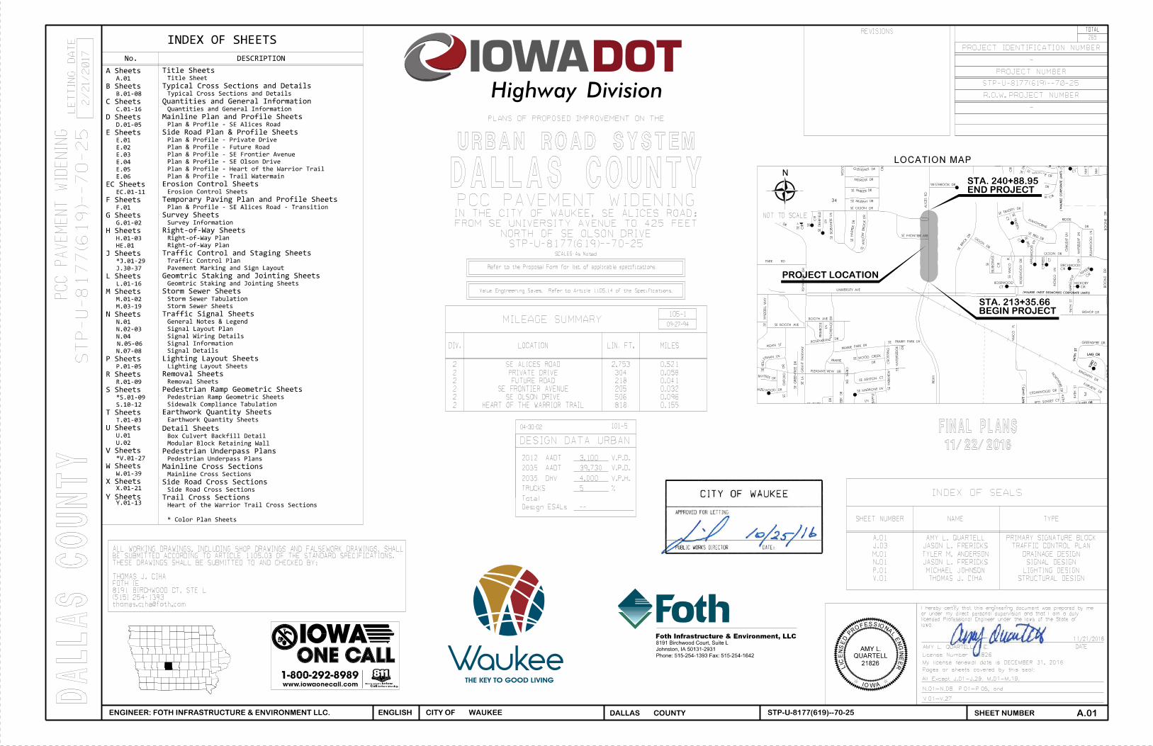

CITY OF WAUKEE, IA - STP-U-8177(619)--70-25
SHEET NO.PROJECT NO: 0016A001.01 DESIGNED BY: J. FRERICKS NO DATE BY REVISION DESCRIPTIONSE ALICES ROAD IMPROVEMENTS S U B J E C T T O C H A N G E
SE ALICES ROADC.02UNIVERSITY AVENUE TO NORTH OF SE OLSON DRIVE
ESTIMATED QUANTITIESCAD FILE: c:\pw_workdir\pw_ie\jlf1\dms82998\0016W021.01_C01_SHT.xlsm
CAD DATE: 11/21/2016 2:49:30 PM DRAWN BY: J. FRERICKS
PROJECT DATE: OCTOBER 2016 CHECKED BY: A. QUARTELL
1 2101-0850001 CLEARING AND GRUBBINGThis bid item shall include all equipment, labor and other miscellaneous related work required to properlyremove and dispose of existing trees, stumps, hedges and other miscellaneous items. Burning will not beallowed. Wood chips shall be hauled off site. Incidental to this item is the removal of all necessarylandscaping features, plantings, edgers, pavers, other debris and abandoned utilities encounteredduring construction. Contractor shall verify all removals with the Engineer and the City. Included in thisitem is tree removal including 5,600 sf of tree removal between Station 228+00 and Station 229+50.
---------- ------------- --------------------------------------------------------------------------------------------------------------2 2102-2710070 EXCAVATION, CLASS 10, ROADWAY & BORROW3 2102-2710090 EXCAVATION, CLASS 10, WASTE
Refer to T-sheets for detailed information. Grading for the side slopes and sidewalk on the east side of SE Alices Road shall to be completed first in the sequence. This bid item includes the following quantities:
22562 CY of total available CUT (CLASS 10 + ROCK UNDERCUT)17356 CY of CUT with 1.3 Shrink13203 CY of total FILL4153 CY net WASTE with 1.3 Shrink
The volume of fill was calculated using a 30% shrink factor for on-site cut material. Compact to a minimum of 95% of standard proctor density. Payment for this item shall be based on the given plan quantity. Place unsuitable materials a minimum of 2 feet below proposed pavement.
Suitable borrow material with moisture and density control shall meet the following requirements: 95 pcf orgreater density (AASHTO T 99 Proctor Density), AASHTO M 145-91 index of less than 30, and Liquid Limit (LL)less than 50.
---------- ------------- --------------------------------------------------------------------------------------------------------------4 2102-4560000 LOCATING TILE LINES
Item included for locating and repairing existing field tile encountered during grading operations and for connecting existing tile to proposed storm system. Quantity for payment will be field measured and approved by the Engineer.
---------- ------------- --------------------------------------------------------------------------------------------------------------5 2105-8425015 TOPSOIL, STRIP, SALVAGE AND SPREAD
Refer to T-sheets for detailed information. Strip and salvage topsoil to a depth of 8 inches before excavation occurs. Topsoil to be spread to a minimum of 8 inches thick. This bid item includes the following quantities:
7882 CY of stripping
100-4A10-29-02
ESTIMATE REFERENCE INFORMATIONItem No. Item Code Description
1 2101-0850001 CLEARING AND GRUBBING ACRE 102 2102-2710070 EXCAVATION, CLASS 10, ROADWAY & BORROW CY 225623 2102-2710090 EXCAVATION, CLASS 10, WASTE CY 41534 2102-4560000 LOCATING TILE LINES STA 45 2105-8425015 TOPSOIL, STRIP, SALVAGE AND SPREAD CY 78826 2107-0875000 COMPACTION WITH MOISTURE AND DENSITY CONTROL CY 102467 2113-0001000 SUBGRADE STABILIZATION MATERIAL, CRUSHED STONE SY 5008 2113-0001100 SUBGRADE STABILIZATION MATERIAL, POLYMER GRID SY 5009 2115-0100000 MODIFIED SUBBASE CY 536610 2121-7425010 GRANULAR SHOULDERS, TYPE A TON 47011 2301-1033100 STANDARD OR SLIP FORM PCC PAVEMENT, CLASS C, CLASS 3 DURABILITY, 10 IN. SY 2795512 2301-4874106 MEDIAN, DOWELLED P.C. CONCRETE, 6 INCH SY 55813 2301-6911722 PORTLAND CEMENT CONCRETE PAVEMENT SAMPLES LS 114 2304-0101000 TEMPORARY PAVEMENT SY 463215 2315-8275025 SURFACING, DRIVEWAY, CLASS A CRUSHED STONE TON 3416 2401-6750001 REMOVALS, AS PER PLAN LS 117 2402-0425031 GRANULAR BACKFILL TON 226518 2402-0425040 FLOODED BACKFILL CY 29019 2402-2720000 EXCAVATION, CLASS 20 CY 346320 2403-0100000 STRUCTURAL CONCRETE (MISCELLANEOUS) CY 26221 2403-0100020 STRUCTURAL CONCRETE (RCB) CY 29622 2404-7775000 REINFORCING STEEL LB 8824023 2414-6460000 ORNAMENTAL METAL RAILING LF 96224 2416-0100015 APRON, CONC, 15" EACH 125 2416-0100018 APRON, CONC, 18" EACH 126 2416-0100024 APRON, CONC, 24" EACH 227 2416-0100036 APRON, CONC, 36" EACH 128 2430-0000100 MODULAR BLOCK RETAINING WALL SF 59329 2435-0140148 MANHOLE, STORM SEWER, SW-401, 48 IN. EACH 330 2435-0140172 MANHOLE, STORM SEWER, SW-401, 72 IN. EACH 131 2435-0140196 MANHOLE, STORM SEWER, SW-401, 96 IN. EACH 132 2435-0250100 INTAKE, SW-501 EACH 733 2435-0250300 INTAKE, SW-503 EACH 534 2435-0250500 INTAKE, SW-505 EACH 335 2435-0250600 INTAKE, SW-506 EACH 236 2435-0250610 INTAKE, SW-506 MODIFIED EACH 137 2435-0251224 INTAKE, SW-512, 24" EACH 238 2435-0251236 INTAKE, SW-512, 36" EACH 339 2435-0600020 MANHOLE ADJUSTMENT, MAJOR EACH 1540 2435-0600120 INTAKE ADJUSTMENT, MAJOR EACH 541 2435-0700010 SW-211, CONNECTION TO EXISTING STORM SEWER STRUCTURE EACH 642 2501-8400172 TEMPORARY SHORING LS 143 2502-8213106 SUBDRAIN, PVC, STANDARD, PERFORATED, 6 IN. LF 238844 2502-8221006 SUBDRAIN RISER, 6 IN. EACH 445 2502-8221303 SUBDRAIN OUTLET, DR-303 EACH 2046 2503-0111012 STORM SEWER GRAVITY MAIN, TRENCHED, (HDPE), 12 IN. LF 25147 2503-0114218 STORM SEWER GRAVITY MAIN, TRENCHED, RCP, 2000D (CLASS III), 18 IN. LF 99548 2503-0114224 STORM SEWER GRAVITY MAIN, TRENCHED, RCP, 2000D (CLASS III), 24 IN. LF 36349 2503-0114230 STORM SEWER GRAVITY MAIN, TRENCHED, RCP, 2000D (CLASS III), 30 IN. LF 4550 2503-0114236 STORM SEWER GRAVITY MAIN, TRENCHED, RCP, 2000D (CLASS III), 36 IN. LF 107051 2503-0114615 STORM SEWER GRAVITY MAIN, TRENCHED, RCP, 3750D (CLASS V), 15 IN. LF 104352 2503-0200036 REMOVE STORM SEWER PIPE LESS THAN OR EQUAL TO 36 IN. LF 104453 2504-0150410 SANITARY SEWER FORCE MAIN, TRENCHED, (PVC), 10 IN. LF 13054 2502-2308110 CONTINUOUS TRENCH DRAIN (500-20) LF 2555 2507-8029000 EROSION STONE TON 3056 2510-6745850 REMOVAL OF PAVEMENT SY 1480457 2510-6750600 REMOVAL OF INTAKES AND UTILITY ACCESSES EACH 758 2511-0300000 REMOVAL OF RECREATION TRAIL SY 81059 2511-0302600 RECREATIONAL TRAIL, PORTLAND CEMENT CONCRETE, 6 IN. SY 289360 2511-6745900 REMOVAL OF SIDEWALK SY 29661 2511-7526005 SIDEWALK, P.C. CONCRETE, 5 IN. SY 86862 2511-7528101 DETECTABLE WARNINGS SF 32863 2515-2475008 DRIVEWAY, P.C. CONCRETE, 8 IN. SY 100164 2515-6745600 REMOVAL OF PAVED DRIVEWAY SY 204665 2518-6910000 SAFETY CLOSURE EACH 1266 2523-0000100 LIGHTING POLES EACH 2067 2523-0000200 ELECTRICAL CIRCUITS LF 590368 2523-0000310 HANDHOLES AND JUNCTION BOXES EACH 2369 2523-0000400 CONTROL CABINET EACH 170 2524-6765210 REMOVAL OF TYPE A SIGN ASSEMBLY EACH 4971 2524-9089100 DELINEATOR, RIGID - TYPE I EACH 472 2524-9276010 PERFORATED SQUARE STEEL TUBE POSTS LF 51873 2524-9325001 TYPE A SIGNS, SHEET ALUMINUM SF 35574 2525-0000100 TRAFFIC SIGNALIZATION LS 175 2526-8285000 CONSTRUCTION SURVEY LS 176 2527-9263109 PAINTED PAVEMENT MARKING, WATERBORNE OR SOLVENT-BASED STA 13177 2527-9263117 PAINTED PAVEMENT MARKINGS, DURABLE STA 8878 2527-9263131 WET RETROREFLECTIVE REMOVABLE TAPE MARKINGS STA 191
100-1A07-15-97
ESTIMATED PROJECT QUANTITIES
(1 DIVISION PROJECT)Item No. Item Code Item Unit Total As Built Qty.
79 2527-9263137 PAINTED SYMBOLS AND LEGENDS, WATERBORNE OR SOLVENT-BASED EACH 1380 2527-9263143 PAINTED SYMBOLS AND LEGENDS, DURABLE EACH 2981 2527-9263152 PRE-CUT SYMBOLS AND LEGENDS, REGULAR MARKING TAPE EACH 1482 2527-9263180 PAVEMENT MARKINGS REMOVED STA 883 2528-8400048 TEMPORARY BARRIER RAIL, CONCRETE LF 455184 2528-8445110 TRAFFIC CONTROL LS 185 2528-8445113 FLAGGERS EACH 1586 2528-9290050 PORTABLE DYNAMIC MESSAGE SIGN (PDMS) CDAY 24087 2533-4980005 MOBILIZATION LS 188 2554-0114012 WATER MAIN, TRENCHED, POLYVINYL CHLORIDE PIPE (PVC), 12 IN. LF 61089 2554-0202400 FITTINGS BY COUNT, POLYVINYL CHLORIDE (PVC), EACH 790 2554-0207012 VALVE, GATE, DIP, 12 IN. EACH 491 2554-0208012 TAPPING VALVE ASSEMBLY, 12 IN. EACH 492 2554-0210201 FIRE HYDRANT ASSEMBLY, WM-201 EACH 1093 2599-9999005 ADJUSTMENT OF FIXTURES EACH 2094 2599-9999005 WATERMAIN VERTICAL RELOCATION EACH 295 2599-9999010 SUBMERSIBLE CENTRIFUGAL STORMWATER PUMPS LS 196 2599-9999010 ELECTRICAL SYSTEM FOR STORMWATER PUMPS LS 197 2599-9999010 STORMWATER POLLUTION PREVENTION PLAN (SWPPP), MANAGEMENT LS 198 2599-9999010 UNDERPASS LIGHTING LS 199 2599-9999018 ANTI-GRAFFITI COATING SY 975100 2599-9999020 GRANULAR BEDDING TON 525101 2601-2634100 MULCHING ACRE 7102 2601-2636044 SEEDING AND FERTILIZING (URBAN) ACRE 7103 2601-2642120 STABILIZING CROP - SEEDING AND FERTILIZING (URBAN) ACRE 10104 2602-0000020 SILT FENCE LF 3656105 2602-0000030 SILT FENCE FOR DITCH CHECKS LF 810106 2602-0000071 REMOVAL OF SILT FENCE OR SILT FENCE FOR DITCH CHECKS LF 3465107 2602-0000101 MAINTENANCE OF SILT FENCE OR SILT FENCE FOR DITCH CHECK LF 347108 2602-0000130 TEMPORARY SEDIMENT CONTROL BASIN EACH 32109 2602-0000312 PERIMETER AND SLOPE SEDIMENT CONTROL DEVICE, 12 IN. DIA. LF 1320110 2602-0000350 REMOVAL OF PERIMETER AND SLOPE SEDIMENT CONTROL DEVICE LF 1320111 2602-0010010 MOBILIZATIONS, EROSION CONTROL EACH 3112 2602-0010020 MOBILIZATIONS, EMERGENCY EROSION CONTROL EACH 1
100-1A07-15-97
ESTIMATED PROJECT QUANTITIES
(1 DIVISION PROJECT)Item No. Item Code Item Unit Total As Built Qty.

SHEET NO.PROJECT NO: 0016A001.01 DESIGNED BY: J. FRERICKS NO DATE BY REVISION DESCRIPTION
11/21/2016 1:41:43 PM DRAWN BY: J. FRERICKS
SE ALICES ROAD IMPROVEMENTS S U B J E C T T O C H A N G E
CAD FILE: c:\pw_workdir\pw_ie\jlf1\dms82998\0016W021.01_C01_SHT.xlsmC.03UNIVERSITY AVENUE TO NORTH OF SE OLSON DRIVE
ESTIMATED QUANTITIESCITY OF WAUKEE, IA - STP-U-8177(619)--70-25
PROJECT DATE: OCTOBER 2016 CHECKED BY: A. QUARTELLSE ALICES ROAD
CAD DATE:
5310 CY of total available topsoil stripping with 1.5 Shrink1579 CY of respreading3731 CY of EXCESS (Incorporate into Fill areas outside pavement)
The volume of spreading was calculated using a 50% shrink factor for spreading material. This quantity wascalculated by stripping the areas identified on the cross sections (typically upper 8-in. of topsoil plusadditional depth in existing ditches) and placing of topsoil to a depth of 8-in. for finished grading. Thisitem also includes backfilling behind curb and all required fine grading. Payment for this bid item shall be based on the given plan quantity.
---------- ------------- --------------------------------------------------------------------------------------------------------------6 2107-0875000 COMPACTION WITH MOISTURE AND DENSITY CONTROL
Refer to B-sheets for location and details. Item is labeled Subgrade Preparation and shall be 12 inches thick.---------- ------------- --------------------------------------------------------------------------------------------------------------
7 2113-0001000 SUBGRADE STABILIZATION MATERIAL, CRUSHED STONEFor isolated unstable areas of subgrade encountered during construction. Typical means and methods of subgradeconstruction, i.e. discing, rolling, ect., must be attempted prior to use of this item. Prior approval of thisitem must be received before construction begins.
---------- ------------- --------------------------------------------------------------------------------------------------------------8 2113-0001100 SUBGRADE STABILIZATION MATERIAL, POLYMER GRID
For isolated unstable areas of subgrade encountered during construction. Typical means and methods of subgradeconstruction, i.e. discing, rolling, ect., must be attempted prior to use of this item. Prior approval of thisitem must be received before construction begins.
---------- ------------- --------------------------------------------------------------------------------------------------------------9 2115-0100000 MODIFIED SUBBASE
Refer to Tab 100-24 on the C-sheets and B-sheets for details, location, and depth. To be placed a minimum depth of 6" beneath all roadway pavement and includes 3' outside of back of curb and gutter of all roadway pavement.
---------- ------------- --------------------------------------------------------------------------------------------------------------10 2121-7425010 GRANULAR SHOULDERS, TYPE A
Refer to typical sections on B-sheets for shoulder thickness information. Quantity is estimated using an application rate of 2.05 tons/cy.
---------- ------------- --------------------------------------------------------------------------------------------------------------11 2301-1033100 STANDARD OR SLIP FORM PCC PAVEMENT, CLASS C, CLASS 3 DURABILITY, 10 IN.
Refer to Tab 100-24 on C-sheets for details. This item includes the 10" driveway pavement intoGilcrest/Jewett from Private Drive and Future Road.Slip formed pavement shall be C-QMC mix in accordance with Proportion Table 4 of IM 529. To maintain the lowerwater to cement ratio a low or mid-range water reducer may be needed. Well graded aggregates may be used withthe C-QMC mix in proportions to fall within Zone II-A, II-B or II-C in accordance with IM 532.Standard C mix in accordance with Proportion Table 1 of IM 529 shall be utilized with hand finished pavement.Refer to typical sections on B-sheets for pavement reinforcing details and additional information.Refer to L-sheets for additional details. Certified plant inspection shall be provided by the contractor.Refer to Tab 100-27 on C-sheets and Standard Specification Section 2316 for Pavement Smoothness. Refer to Standard Specification Section 2521 for Certified Plant Inspection. Refer to Iowa DOT Standard Road Plan PR-120 for details of reinforced pavement over box culverts.
---------- ------------- --------------------------------------------------------------------------------------------------------------12 2301-4874106 MEDIAN, DOWELLED P.C. CONCRETE, 6 INCH
Refer to B-sheets for SUDAS Detail 7010.906.---------- ------------- --------------------------------------------------------------------------------------------------------------
13 2301-6911722 PORTLAND CEMENT CONCRETE PAVEMENT SAMPLES---------- ------------- --------------------------------------------------------------------------------------------------------------
14 2304-0101000 TEMPORARY PAVEMENTRefer to Tab 100-24 on C-sheets and J-sheets for additional information. This item is for temporary pavement for access during construction and the propsed temporary transition Sta 1237+40.85 to Sta 1239+71.99 on SE Alice Road. Contractor has the option to use HMA Full-depth or PCC pavement. Pavement thickness shall match adjacent pavement when new temporary pavement is installed on subbase. HMA overlay with a minimum thickness of 2-inches shall be used when temporary pavement is installed over existing pavement to meet grades.
---------- ------------- --------------------------------------------------------------------------------------------------------------15 2315-8275025 SURFACING, DRIVEWAY, CLASS A CRUSHED STONE
This item is for the granular entrance located along Alices Road at Station 1238+90. Estimated quantity isbased on 10" depth of crushed stone. Refer to SUDAS detail 9040.20 on the B-sheets except thickness shallbe 10 inches. Quantity is estimated using an application rate of 2.05 tons/cy.
---------- ------------- --------------------------------------------------------------------------------------------------------------16 2401-6750001 REMOVALS, AS PER PLAN
This item is for the removal and disposal of existing signs and fire hydrants. Refer to Tab 110-2 on the C-sheets for location of removal of a sign on SE Olson Drive and a sign at Gilcrest/Jewett parking lot. Payment shall include necessary material, equipment, and labor to remove entire structures. Gilcrest/Jewett sign shall be delivered to the property owner.Refer to Tab FOTH-2 on C-sheets and D-sheets for locations of fire hydrants to be removed. This item shall include removing hydrants assemblies including hydrant and valve and backfilling trench. Compact trenches to 95% Standard Proctor Density. The City will provide density testing.
---------- ------------- --------------------------------------------------------------------------------------------------------------17 2402-0425031 GRANULAR BACKFILL18 2402-0425040 FLOODED BACKFILL19 2402-2720000 EXCAVATION, CLASS 20
Refer to V-sheets for details.---------- ------------- --------------------------------------------------------------------------------------------------------------
20 2403-0100000 STRUCTURAL CONCRETE (MISCELLANEOUS)21 2403-0100020 STRUCTURAL CONCRETE (RCB)
Refer to V-sheets for details.---------- ------------- --------------------------------------------------------------------------------------------------------------
100-4A10-29-02
ESTIMATE REFERENCE INFORMATIONItem No. Item Code Description
22 2404-7775000 REINFORCING STEELRefer to V-sheets for details.
---------- ------------- --------------------------------------------------------------------------------------------------------------23 2414-6460000 ORNAMENTAL METAL RAILING
Refer to V-sheets for details for railing installed on the Heart of the Warrior Trail retaining wall. SeeB-sheets and U-sheets for railing installed adjacent to modular block retaining walls on SE Alices Road.
---------- ------------- --------------------------------------------------------------------------------------------------------------24 2416-0100015 APRON, CONC, 15"25 2416-0100018 APRON, CONC, 18"26 2416-0100024 APRON, CONC, 24"27 2416-0100036 APRON, CONC, 36"
Refer to List of Intakes and Utility Access (104-5B) on sheet M.01.This includes the installation and supply of apron footing, pipe connectors and galvanized steel apron guards.Last three pipe joints prior to end of apron shall be tied. Refer to concrete footing detail in B-sheets.
---------- ------------- --------------------------------------------------------------------------------------------------------------28 2430-0000100 MODULAR BLOCK RETAINING WALL
Refer to U-sheets for location and details. Refer to B-sheets for design details. Contractor shall use the same modular block size and color found at the Gilcrest Jewett retaining wall. Retaining wall block shall be approximately 8" H x 12" D x 16" L. Cap block shall be 4" H x 12" D with a 14"x16" trapizotal top. Item includes subdrain, backfill, stabilization material, cap block, pins and all other materials to installretaining wall. The Contractor shall provide the structural design and details signed and sealed by aStructural Engineer licensed in the State of Iowa.
---------- ------------- --------------------------------------------------------------------------------------------------------------29 2435-0140148 MANHOLE, STORM SEWER, SW-401, 48 IN.30 2435-0140172 MANHOLE, STORM SEWER, SW-401, 72 IN.31 2435-0140196 MANHOLE, STORM SEWER, SW-401 96 IN.32 2435-0250100 INTAKE, SW-50133 2435-0250300 INTAKE, SW-50334 2435-0250500 INTAKE, SW-50535 2435-0250600 INTAKE, SW-50636 2435-0250610 INTAKE, SW-506 MODIFIED
See B-Sheets for SW-506 Modified 2 detail.37 2435-0251224 INTAKE, SW-511, 24"38 2435-0251236 INTAKE, SW-512, 36"
Refer to List of Intakes and Utility Accesses in M-sheets. Pre-cast structures will be allowed.Adjustment rings will not be allowed. Adjustments shall be constructed integral to the boxout pour.By-pass pumping required to complete construction of structures shall be considered incidental.
---------- ------------- --------------------------------------------------------------------------------------------------------------39 2435-0600020 MANHOLE ADJUSTMENT, MAJOR
This item includes all materials, labor, and equipment necessary to adjust existing manholes to proposed rim elevations. Refer to Tab 104-10 on the C-sheets and D-sheets for locations and details.
---------- ------------- --------------------------------------------------------------------------------------------------------------40 2435-0600120 INTAKE ADJUSTMENT, MAJOR
This item includes all materials, labor, and equipment necessary to adjust existing intakes to proposed form grade elevations. Refer to Tab 104-10 on the C-sheets and D-sheets for locations and details.
---------- ------------- --------------------------------------------------------------------------------------------------------------41 2435-0700010 CONNECTION TO EXISTING STORM SEWER STRUCTURE
Refer to M-sheets for information and locations. New opening shall be core drilled and collar poured.Contractor to verify flowlines of existing storm sewer pipes prior to laying new pipe and core drilling andnotify the Engineer if elevations differ from those in the plans.
---------- ------------- --------------------------------------------------------------------------------------------------------------42 2501-8400172 TEMPORARY SHORING
Refer to V-sheets for details.---------- ------------- --------------------------------------------------------------------------------------------------------------
43 2502-8213106 SUBDRAIN, PVC, CASE A, 6 IN.Refer to M-sheets for subdrain locations and Longitudinal Subdrain Tabulation (104-9). Approved manufactures:(1) Contech, A-2000 (2) Advanced Drainage Systems, ADS N-12 or (3) Hanor, HI-QIncludes porous backfill, tees, plugs and all other required fittings. Refer to figure 4040.231 in B-sheets forconstruction details. Engineering fabric will not be required.
44 2502-8221303 SUBDRAIN RISER, 6 IN.Subdrain type-A cleanout; refer to details on B-sheets and M-sheets for locations and Tabulation of Subdrains. The contractor will be paid the contract unit price per each. This shall be considered full compensation for furnishing all materials, equipment and labor for each subdrain cleanout.
45 2502-8221303 SUBDRAIN OUTLET, DR-303Refer to details on B-sheets, M-sheets for locations and Tabulation of Subdrains.
---------- ------------- --------------------------------------------------------------------------------------------------------------46 2503-0111012 STORM SEWER GRAVITY MAIN, TRENCHED, (HDPE), 12 IN. 47 2503-0114218 STORM SEWER GRAVITY MAIN, TRENCHED, RCP, 2000D (CLASS III), 18 IN.48 2503-0114224 STORM SEWER GRAVITY MAIN, TRENCHED, RCP, 2000D (CLASS III), 24 IN.49 2503-0114230 STORM SEWER GRAVITY MAIN, TRENCHED, RCP, 2000D (CLASS III), 30 IN.50 2503-0114236 STORM SEWER GRAVITY MAIN, TRENCHED, RCP, 2000D (CLASS III), 36 IN.51 2503-0114615 STORM SEWER GRAVITY MAIN, TRENCHED, RCP, 3750D (CLASS V), 15 IN.
Refer to List of Storm Sewer Pipe (104-5B) on sheet M.01, the M-Sheets locations and details.Bedding shall be Class R-2 for all RCP pipe and Class R-5 for all RCAP. Wrap pipe joints with engineering fabric and backfill with granular bedding material/backfill to a minimum of 6-in above top of pipe for all RCP storm sewer unless otherwise noted in the plans. Storm sewer 18" diameter and less shall be bell and spigot joint pipe. Compact trenches to a minimum of 95% standard proctor density. Incidental to this item is disposal of non-desirable backfill material and replacing with suitable material from elsewhere on the project site. Granular bedding and backfill material is incidental to this item. The City will provide Density testing. Item includes dewatering for storm sewer construction and connections to existing pipe.
100-4A10-29-02
ESTIMATE REFERENCE INFORMATIONItem No. Item Code Description

CAD DATE: 11/21/2016 1:41:43 PM DRAWN BY: J. FRERICKS
SE ALICES ROAD IMPROVEMENTS
CITY OF WAUKEE, IA - STP-U-8177(619)--70-25
PROJECT DATE: OCTOBER 2016 CHECKED BY:
SHEET NO.PROJECT NO: 0016A001.01 DESIGNED BY: J. FRERICKS NO DATE BY REVISION DESCRIPTION
A. QUARTELLSE ALICES ROAD
S U B J E C T T O C H A N G E
CAD FILE: c:\pw_workdir\pw_ie\jlf1\dms82998\0016W021.01_C01_SHT.xlsmC.08UNIVERSITY AVENUE TO NORTH OF SE OLSON DRIVE
ESTIMATED QUANTITIES
35 or less 40 - 45 over 45SE Alices Road 216+95.45 240+88.95 X
Private Drive 702+09.62 706+02.52 X
Future Road 504+00.00 509+94.76 X
SE Frontier Avenue 303+65.00 305+31.59 X
SE Olson Drive 101+07.23 107+01.07 X
100-2710-20-09
PAVEMENT SMOOTHNESS + PCC TEXTURE
Road Identification Begin Station End StationProposed Posted Speed
Remarks
SY CY CY215+28.08 218+46.51 6 inch, dowelled 252.4 SE Alices Road219+17.93 224+09.17 6 inch, dowelled 160.7 SE Alices Road224+80.17 226+31.69 6 inch, dowelled 50.4 SE Alices Road232+32.45 234+66.96 6 inch, dowelled 78.1 SE Alices Road235+73.79 236+24.25 6 inch, dowelled 16.6 SE Alices Road
Remarks
112-510-20-15
CONCRETE MEDIANS * Bid item
Begin
Station
End
StationType
Area*Modified
Subbase
Special
Backfill
FT FT SY SY SY SY SY SY SY SY SY 10 IN 8 IN TONS CY CY
SE Alices Road Both 216+97.66 224+16.05 Var. 718.4 7190.0 7190.0 1269.2 2538.4 Mainline - 10" ReinforcedSE Alices Road Both 224+16.05 232+32.45 Var. 816.4 7828.0 7828.0 1517.4 3034.8 Mainline - 10" ReinforcedSE Alices Road Both 232+32.45 237+40.85 Var. 508.4 5878.0 5878.0 1031.5 2063.0 Mainline - 10" ReinforcedSE Alices Road Both 237+40.85 240+88.95 Var. 348.1 973.0 973.0 187.2 374.4 Temporary Pavement - 10" PCC or HMASE Alices Road 221+67.85, LT Var. Var. 112.7 112.7 26.3 Driveway - 8"SE Alices Road 226+90.68, LT Var. Var. 277.0 277.0 53.8 Driveway - 8"SE Alices Road 232+18.94, LT Var. Var. 109.0 109.0 25.5 Driveway - 8"SE Alices Road 239+73.17, RT Var. Var. 118.9 119.0 24.8 Driveway - 8"
Private Drive Both 702+09.62 703+55.35 Var. 145.7 625.0 625.0 117.5 235.0 Side Road - 10" ReinforcedPrivate Drive Both 704+44.59 706+02.52 Var. 157.9 638.0 638.0 124.3 248.6 Side Road - 10" ReinforcedPrivate Drive 702+34.58, LT Var. Var. 131.0 131.0 28.1 Driveway - 10"Private Drive 702+34.33, RT Var. 11.2 31.4 31.0 8.0 Driveway - 8"
Future Road Both 502+00.00 504+00.00 Var. 200.0 644.0 644.0 127.4 254.8 Side Road - 10" ReinforcedFuture Road Both 504+00.00 505+55.50 Var. 155.5 735.3 735.0 136.7 273.4 Side Road - 10" ReinforcedFuture Road 502+63.47, LT Var. 38.8 174.0 174.0 33.5 Driveway - 8"Future Road 504+38.30, RT Var. 16.8 61.2 61.0 11.9 Driveway - 10"Future Road 504+88.76, LT Var. 22.3 71.6 72.0 14.8 Driveway - 8"
SE Frontier Avenue Both 303+65.00 305+31.59 Var. 166.6 573.0 573.0 113.9 227.8 Side Road - 10" Reinforced
SE Olson Drive Both 101+07.29 104+77.54 Var. 370.3 2000.0 2000.0 372.3 744.6 Side Road - 10" ReinforcedSE Olson Drive Both 105+90.54 107+01.07 Var. 110.5 679.0 679.0 125.6 251.2 Side Road - 10" ReinforcedSE Olson Drive 102+88.99, RT Var. 22.8 106.0 106.0 16.6 Driveway - 8"
SY
Subgrade
Prep Remarks
Total Area By
Pavement ThicknessSpecial
Backfill
Modified
SubbaseArea
Location Mainline Area
Road IdentificationDirection
of TravelStation to Station
Width Length
Quantity includes Pavement Header.
100-2404-21-15
PCC PAVEMENT
Does not include raised island area or curb. Refer to tabulation
112-4 for quantities.
Refer to PV-410, PV-411, PV-412, and PV-414.
A
3
1
2
C D E F G HB
3
1 2


31 DETECTOR LOOP SYMBOL AND IDENTIFYING NUMBER
CABINET AND CONTROLLER
POWER SOURCE
LUMINAIRE
SIGNAL LEGEND
TRENCHED SIGNAL CONDUIT
PUSHED SIGNAL CONDUIT
MICROWAVE DETECTOR
WOODEN SIGNAL POLE AND IDENTIFYING NUMBER
EMERGENCY VEHICLE PREEMPTION
PEDESTRIAN HEAD SYMBOL AND IDENTIFYING NUMBER
MAST ARM MOUNTED SIGN SYMBOL AND IDENTIFYING NUMBER
42
TRAFFIC SIGNAL HEAD SYMBOL AND IDENTIFYING NUMBER
VIDEO DETECTION AREA SYMBOL AND IDENTIFYING NUMBER
SYMBOL/LABEL DESCRIPTION
PEDESTAL POLE, FOOTING SYMBOL, AND IDENTIFYING NUMBER
PEDESTRIAN PUSHBUTTON IDENTIFYING NUMBER
EXISTING SIGNAL CONDUIT
1E
4
1
4E
C
323
81
23
25
1
3
1
TS
EXISTING JUNCTION BOX SYMBOL AND IDENTIFYING NUMBER
24" HANDHOLE (TYPE I) SYMBOL AND IDENTIFYING NUMBER
FIBER OPTIC HUB CABINET
PTZ CAMERA
NUMBER30"x48" "TUB" HANDHOLE (TYPE III) SYMBOL AND IDENTIFYING
NUMBERTRAFFIC SIGNAL POLE, FOOTING SYMBOL, AND IDENTIFYING
IDENTIFYING NUMBEREXISTING TRAFFIC SIGNAL POLE, FOOTING SYMBOL, AND
IDENTIFYING NUMBERTRAFFIC SIGNAL HEAD WITH BACKPLATE SYMBOL AND
REPRESENT EXISTING EQUIPMENT.
LABELS WITH AN IDENTIFYING NUMBER FOLLOWED BY THE LETTER "E"
REPRESENT FUTURE EQUIPMENT AND WILL NOT INCLUDED IN THIS PROJECT.
LABELS WITH AN IDENTIFYING NUMBER FOLLOWED BY THE LETTER "F"
BATTERY BACKUP CABINET
TRAFFIC SIGNAL PROJECT NOTES
GENERAL NOTES & LEGENDN.01
1 2/09/2017 JSW SYMBOL INDICATES REVISION
1
1
1
1
1
1
1
1
1
1
1
1
1
1
1
1
1
1
1
1
1
SERVICE.
COORDINATE WITH CITY 48-HOURS PRIOR TO ANY SPLICING OF FIBER OPTIC CABLES TO MINIMIZE LOSS OF 32.
SEE P-SHEETS FOR LUMINAIRE INFORMATION.31.
STORM EVENT.
CONTRACTOR SHALL CLEAN ALL STREETS OPEN TO PUBLIC AT THE END OF EACH WORK DAY AND PRIOR TO ANY 30.
BY APPROVED IADOT METHODS.
TRAFFIC SIGNAL POLES, MAST ARMS, PEDESTAL POLES, BASES, AND HARDWARE SHALL BE COLORED RAL 7043 29.
CONTRACTOR TO TERMINATE ALL SPARE SIGNAL CONDUCTORS TO THE GROUND BUSS BAR.28.
UTILTITY CONFLICT.
THAT SITE. THE CONTRACTOR IS RESPONSIBLE FOR CONTACTING THE ENGINEER UPON DETERMINATION OF ANY
TO DETERMINE ANY CONFLICTS WITH UTILTIES AT SITES IN THE FIELD PRIOR TO INITIATION OF CONSTRUCTION AT
WITHOUT FULL CONSIDERATION OF EXISTING GROUND UTILTIES. IT SHALL BE THE CONTRACTOR'S RESPONSIBILITY
LOCATION OF THE CONDUIT SYSTEM AND HANDHOLES ON THE PLANS BY THE ENGINEER HAS BEEN PERFORMED 27.
INCLUDING NETWORK COMPATIBILITY.
SHALL BE SUPPLIED TO CONNECT THE PROPOSED TRAFFIC SIGNAL TO THE CITY'S EXISTING FIBER SYSTEM
THE CONTROLLER SHALL BE NTCIP COMPLIANT AND ETHERNET / FIBER READY. ALL MATERIALS AND EQUIPMENT 26.
AND NON-FUSED KITS.
FOR STREET LIGHTING POWER FEEDS, THE CONTRACTOR SHALL INSTALL FLOOD-SEAL IN-LINE AND WYE FUSED 25.
FOR TOP OF FOOTING ELEVATIONS.
PRIOR TO INSTALLING TRAFFIC SIGNAL POLE FOOTINGS, THE CONTRACTOR SHALL CONTACT THE PROJECT ENGINEER 24.
OTHERWISE DIRECTED BY THE PROJECT ENGINEER.
INTERSECTION SUCH THAT THE SIGNAL HEADS CAN BE VIEWED WHILE FACING THE CONTROLLER, UNLESS
THE TRAFFIC SIGNAL CONTROLLER CABINET SHALL BE ORIENTED WITH THE BACK OF THE CABINET TOWARD THE 23.
THE POWER SERVICE FOR THE TRAFFIC SIGNAL WITH MIDAMERICAN ENERGY.
THE CONTRACTOR SHALL VERIFY THE LOCATION OF THE POWER SERVICE AND COORDINATE THE CONNECTION TO 22.
SPECIFICATIONS. TRAFFIC SIGNAL HEAD COLORS SHALL HAVE BLACK FACES, VISORS, BODIES, AND BACKPLATES.
ALL TRAFFIC AND PEDESTRIAN INDICATIONS SHALL BE LED IN ACCORDANCE WITH THE MOST RECENT ITE 21.
A UNIVERSALLY ADJUSTABLE MOUNTING BRACKET.
THE MAST ARM MOUNTED SIGNAL HEADS, TRAFFIC SIGNS, AND STREET NAME SIGNS SHALL BE MOUNTED BY USING 20.
RECOMMENDATIONS FOR NATIONAL ELECTRICAL CODE (NEC) REQUIREMENTS.
THE MINIMUM BENDING RADIUS OF THE CONDUIT SYSTEM SHALL BE THE LARGER OF THE MANUFACTURER'S 19.
CONDUIT. TRACER WIRE SHALL BE INSTALLED IN ALL NEW CONDUITS.
BEND, AN APPROVED CONDUIT HEATING DEVICE SHALL BE USED. DIRECT FLAME SHALL NOT BE APPLIED TO THE
ALL CONDUIT SHALL BE SCHEDULE 40 PVC OR HDPE SDR 13.5. WHEN HEATING PVC CONDUIT TO FORM A 18.
TRAFFIC SIGNAL INTO OPERATION AND ANY WEEKEND OR HOLIDAY WORK TO BE SCHEDULED.
NOTIFY THE CITY OF WAUKEE AND THE PROJECT ENGINEER 48 HOURS IN ADVANCE OF PLACING THE PROPOSED 17.
IDENTIFY AND LABEL STREET LIGHT WIRING IN POLE BASES.16.
OF 4:00 - 6:00 PM.
NO LANE CLOSURES WILL BE PERMITTED BETWEEN THE HOURS OF 7:00 - 9:00 AM, OR BETWEEN THE HOURS 15.
HANDHOLES SHALL NOT BE PLACED IN DITCH BOTTOMS.14.
SIGNAL TECHNICIAN CERTIFICATE.
CONTRACTOR SHALL HAVE AN EMPLOYEE ON THE PROJECT SITE AT ALL TIMES WITH A LEVEL II IMSA TRAFFIC
THE CONTRACTOR SHALL HAVE A MINIMUM OF THREE (3) YEARS EXPERIENCE INSTALLING TRAFFIC SIGNALS. THE 13.
FOR ALL SIGNAL WIRE CONNECTIONS.
SIGNAL WIRING SHALL ONLY BE SPLICED IN POLE BASES OR SIGNAL CABINETS. USE SILICONE FILLED WIRE NUTS 12.
THE CONTROLLER CABINET TO FORM A CONTINUOUSLY GROUNDED SYSTEM.
INSTALL A #6 A.W.G. BARE COPPER GROUND WIRE BETWEEN THE GROUND RODS IN THE SIGNAL FOOTINGS AND 11.
COPPER WIRE CONNECTED BY APPROVED CLAMPS.
FORM A CONTINUOUS SYSTEM AND BE EFFECTIVELY GROUNDED. BONDING JUMPERS SHALL BE #6 A.W.G. BARE
120 VOLT SIGNAL/LIGHTING CABLES. ALL POLES, PEDESTALS, AND CONTROLLER CABINETS SHALL BE BONDED TO
A #6 A.W.G. BARE COPPER GROUND WIRE SHALL BE INSTALLED IN ALL PVC AND HDPE CONDUITS THAT CARRY 10.
CONDUIT THAT WILL CARRY FIBER OPTIC CABLE WILL BE INSTALLED A MINIMUM 42" BELOW FINISH GRADE.
CONDUIT BE BORED UNDER PAVEMENT. PAVEMENT SHALL NOT BE DISTURBED BY CONSTRUCTION. ALL INSTALLED
THE CONTRACTOR HAS THE OPTION TO BORE OR TRENCH CONDUIT; HOWEVER, THE SPECIFICATIONS REQUIRE THAT 9.
UNWRAPPING THE CABLE.
WRAP THE CABLE SO TIGHTLY THAT CITY PERSONNEL CAN NOT REMOVE THE CABLE FROM THE HOOKS WITHOUT
THE CONTRACTOR SHALL USE CARE WHEN WRAPPING SIGNAL CABLE SLACK ON HANDHOLE HOOKS SO AS TO NOT 8.
EXPENSE.
AREAS DISTURBED BY CONSTRUCTION SHALL BE RESTORED TO THEIR ORIGINAL CONDITION AT THE CONTRACTOR'S 7.
PROJECT ENGINEER.
NOTED. THE CONTRACTOR SHALL FIELD VERIFY ALL EQUIPMENT LOCATIONS WITH THE CITY OF WAUKEE AND THE
THE STATIONS/OFFSETS LISTED ON THE SIGNAL PLANS ARE TO THE CENTER OF THE ITEM UNLESS OTHERWISE 6.
DEPARTMENT TO FIELD VERIFY THE PLACEMENT OF ALL SIGNAL HEADS PRIOR TO INSTALLATION.
OVER THEIR RESPECTIVE LANES. THE CONTRACTOR SHALL COORDINATE WITH THE CITY OF WAUKEE ENGINEERING
ALL MAST-ARM MOUNTED VEHICLE SIGNAL HEADS SHALL COME FURNISHED WITH BACK-PLATES AND BE CENTERED 5.
PEDESTRIAN PUSH BUTTON.
FOR EITHER A 4- OR 5-SECTION SIGNAL HEAD, AND A 2-CONDUCTOR CABLE SHALL BE USED FOR EACH
5-CONDUCTOR CABLE SHALL BE USED FOR A 3-SECTION SIGNAL HEAD, A 7-CONDUCTOR CABLE SHALL BE USED
THE CONTRACTOR SHALL INSTALL ONE SIGNAL CABLE FROM EACH SIGNAL HEAD TO THE BASE OF THE POLE. A 4.
CITY OF WAUKEE ENGINEERING DEPARTMENT.
CONTRACTOR SHALL BE RESPONSIBLE FOR ANY CHANGES IMPLEMENTED WITHOUT WRITTEN APPROVAL FROM THE
WAUKEE AND THE ENGINEER AND ARE SUBJECT TO ADJUSTMENT IN THE FIELD BY THE ENGINEER. THE
THE LOCATIONS OF ALL FOOTINGS, HANDHOLES, AND CONDUIT ARE TO BE COORDINATED WITH THE CITY OF 3.
AND PRIOR TO ORDERING POLES FOR THE PURPOSE OF VERIFYING MAST-ARM LENGTHS.
UTILITY COMPANIES, INCLUDING CITY AND/OR STATE OWNED UTILITIES, PRIOR TO EXCAVATION ON THE PROJECT
THE PLAN LOCATIONS OF UNDERGROUND UTILITIES ARE APPROXIMATE ONLY. THE CONTRACTOR SHALL NOTIFY ALL 2.
SPECIFICATIONS, AND SPECIAL PROVISIONS.
SYSTEM INCLUDING TRAFFIC CONTROL AND MOBILIZATION COSTS, IN CONFORMANCE WITH THE PLANS,
AND MATERIALS NECESSARY TO PROVIDE A COMPLETE AND FUNCTIONAL TRAFFIC SIGNAL INSTALLATION AND FIBER
ONLY. THE CONTRACTOR'S LUMP SUM BID FOR THIS BID ITEM SHALL INCLUDE ALL LABOR, TOOLS, EQUIPMENT,
ALL QUANTITIES SHOWN IN THE PLANS AND SPECIFICATIONS ARE FOR INFORMATIONAL AND ESTIMATING PURPOSES 1.
1
SHEET NO.REVISION DESCRIPTIONBYDATENO
CAD FILE:
CAD DATE:
PROJECT DATE:
PROJECT NO:
c:\pw_workdir\pw_ie\jae\dms70194\16W021-01_N01 w Addendum1.SHT.DGN
2/13/2017 12:14:27 PM
DESIGNED BY:
CHECKED BY:
DRAWN BY: J. KOFOOT
A. QUARTELL
J. FRERICKS
UNIVERSITY AVENUE TO NORTH OF SE OLSON DRIVE
SE ALICES ROAD IMPROVEMENTS
CITY OF WAUKEE, IA - STP-U-8177(619)--70-25
16W021.01
OCTOBER 2016

103
104
105
106
234
235
236
2
6463626111
1
4
3
56
7
26
512122232425
31
81
82
66
83
71
41
42
29
27
25
23
53
52
22
24
26
28
51
69
67
65
13
12
62
64
66
68
11
33
83
85
45
43
73
63
72 71
42
44
82
84
3231
6
8
2
4
BC
B
C
CB
D
D
C
B
44
401
402
202
2PB
801
802
1PB
601
1PB
602
2PB
84
65
46
69A
86
29A
43
2PB
201
1
2
4
E
E
5
9
3
HOOK-UP BY UTILITY COMPANY
BOX BASE FOR SECONDARY SERVICE
COIL 50' OF POWER CABLE AT
WITH MIDAMERICAN ENERGY
COORDINATE POWER SERVICE LOCATION
(2 OPENINGS)
DRILL EX MANHOLE
TO TAB 104-10
ADJUST HH REFER
67.12' LT
STA 234+69.38
HANDHOLE (EX)
A
A
A
A
HEAD 24
BAG SIGNAL
HEADS 63 &64
BAG SIGNAL
HEIGHT OF 30'
INSTALL PTZ CAMERA WITH MOUNTING
SIGNAL LAYOUT PLANN.02
SE ALICES RD AND SE OLSON DR
SEE SHEET N.03 FOR NORTH CONTINUATION
SEE SHEET N.03 FOR SOUTH CONTINUATION
1 2/09/2017 JSW SYMBOL INDICATES REVISION1
TRAFFIC SIGNAL FACES
ALL INDICATIONS SHALL BE LED
21
(6-REQ'D)
43,65,66,83
NO. 25,26,
12"
12"
G
FL Y
12"
12"
Y
R
(4-REQ'D)
51,71
NO. 11,31,
ITEM STATION, OFFSET
TRAFFIC
1
2
3
4
2
3
4
5
6
8
HANDHOLES (CTR OF HANDHOLES)
CONTROLLER (CTR OF CABINET)
235+59.39, 93.58' RT
234+53.13, 62.90' RT
234+87.48, 97.45' LT
235+98.85, 59.92' LT
237+79.58, 33.72' LT
7 232+62.72, 57.62' RT
231+54.80, 51.30' RT
5
6
7
235+77.47, 78.34' LT
235+79.30, 62.53' RT
234+81.76, 77.75' RT
234+76.69, 80.23' LT
235+65.98, 77.49' LT
235+65.76, 72.05' RT
234+72.77, 70.00' RT
235+65.14, 93.77' LT
SIGNAL POLES (CTR OF FOOTING)
235+61.57, 87.04' LT1
235+59.34, 106.65' LT9
1
1
12"
12" Y
Y
12"
G
12" G
12" R
(4-REQ'D)
42,82,
NO. 62,23,
12" R
12" G
12" Y
(8-REQ'D)
63,64,81
24,41,61,
NO. 21,22,
1
SHEET NO.REVISION DESCRIPTIONBYDATENO
CAD FILE:
CAD DATE:
PROJECT DATE:
PROJECT NO:
c:\pw_workdir\pw_ie\jae\dms70194\16W021-01_N02 w Addendum1.sht.DGN
2/13/2017 12:14:50 PM
DESIGNED BY:
CHECKED BY:
DRAWN BY: J. KOFOOT
A. QUARTELL
J. FRERICKS
UNIVERSITY AVENUE TO NORTH OF SE OLSON DRIVE
SE ALICES ROAD IMPROVEMENTS
CITY OF WAUKEE, IA - STP-U-8177(619)--70-25
16W021.01
OCTOBER 2016
TRAFFIC SIGNAGE
ONLY
A
ONLY
B
(4-REQ'D)
30"X36"
R3-5L
(4-REQ'D)
30"X36"
R3-5R
SIGNAL CONTRACTOR.
DIMENSIONS. STREET NAME SIGNS SHALL BE SUPPLIED AND INSTALLED BY THE TRAFFIC
INTENTION OF SIGN DETAIL ONLY TO SHOW SIGN WORDING AND SIGN BLANK GENERAL
GREEN BACKGROUND
W/WHITE LETTERS
SE ALICES RD
(2-REQ'D)
84"x18"
D E
GREEN BACKGROUND
W/WHITE LETTERS
(2-REQ'D)
84"x18"
SE OLSON DR
STREET NAME SIGNS
SE OLSON DRIVE
N
O 15
FEET
AND SIGNAL FACE MOUNTINGPEDESTRIAN PUSHBUTTON
1
5 6
7
2
34
5.0'
TY
P.
2.0'
TY
P.
9"
15"
SIGNSPUSHBUTTONPEDESTRIAN
START CROSSING
Watch ForVehicles
DON'T START
Finish Crossing
If Started
DON'T CROSS
TO CROSS
PUSH BUTTON
FLASHING
STEADY
TIME REMAINING
To Finish CrossingTIMER
SE
ALIC
ES
RO
AD
SE OLSON DRIVE
YIELD
LEFT TURN
ON FLASHING
YELLOW
ARROW
LEFT TURN
YIELD
ON FLASHING
YELLOW
ARROW
C
(RIGHT ARROW: 5-REQ'D)
(LEFT ARROW: 3-REQ'D)
9"X15"
R10-3e(4-REQ'D)
30"X36"
R10-12

2
6463626111
1
4
3
56
7
26
512122232425
31
81
82
66
83
71
41
42
29
27
25
23
53
52
22
24
26
28
51
69
67
65
13
12
62
64
66
68
11
33
83
85
45
43
73
63
72 71
42
44
82
84
3231
6
8
2
4
BC
B
C
CB
D
D
C
B
44
401
402
202
2PB
801
802
1PB
601
1PB
602
2PB
84
65
46
69A
86
29A
43
2PB
201
1
2
4
E
E
5
9
3
A
A
A
A
SE ALICES RD AND SE OLSON DR
SIGNAL WIRING DETAILSN.04
14-1c (LOOP)
75' of 1" PVC
GR/TR/PR
2-1c#6 (STLT)
37' of 2" PVC
GR/TR/PR
2-2c (PED PB)
23' of 2" PVC
GR/TR/PR
1-2c#14 (PI)
1-3c#20 (EVP)
1-16c (SIG)
37' of 3" PVC
GR/TR/PR
1-2c (DET)
185' of 2" PVC
GR/TR/PR
2-2c (DET)
191' of 2" PVC
GR/TR/PR
1-2c (DET)
108' of 2" PVC
1
1
2
3
2
4
GR/TR/PR
2-2c (PED PB)
11' of 2" PVC
GR/TR/PR
2-1c#6 (STLT)
181' of 2" PVC
GR/TR/PR
16-2c (DET)
2-2c#14 (PI)
2-3c#20 (EVP)
4-5c (PED PB)
2-16c (SIG)
181' of 4" PVC
GR/TR/PR
4-2c (DET)
1-2c#14 (PI)
1-3c#20 (EVP)
2-5c (PED PB)
1-16c (SIG)
75' of 3" PVC
GR/TR/PR
2-1c#6 (STLT)
75' of 2" PVC
GR/TR/PR
2-1c#6 (STLT)
111' of 2" PVC
7
8
9
7
GR/TR/PR
1-2c (PED PB)
21' of 2" PVC
8
GR/TR/PR
2-1c#6 (STLT)
32' of 2" PVC
9
GR/TR/PR
1-2c#14 (PI)
1-3c#20 (EVP)
1-2c (PED PB)
1-16c (SIG)
32' of 3" PVC
4
3
GR/TR/PR
1-2c#6 (STLT)
18' of 2" PVC
22-1c (LOOP)
145' of 1" PVC
6-1c (LOOP)
70' of 1" PVC
6-1c (LOOP)
45' of 1" PVC
GR/TR/PR
2-1c#6 (STLT)
20' of 2" PVC
GR/TR/PR
1-2c#14 (PI)
1-3c#20 (EVP)
2-2c (PED PB)
1-16c (SIG)
20' of 3" PVC
6-1c (LOOP)
15' of 1" PVC
8-1c (LOOP)
55' of 1" PVC
6
5
5
10-1c (LOOP)
45' of 1" PVC
6
12-1c (LOOP)
50' of 1" PVC
1110
11
10
12
12
13
13
14
14
15
15
16
17
18
19
16
2-1c (LOOP)
17' of 1" PVC
17
2-1c (LOOP)
16' of 1" PVC
18
2-1c (LOOP)
17' of 1" PVC
19
2-1c (LOOP)
18' of 1" PVC
6
4-1c (LOOP)
9' of 1" PVC
21
20
GR/TR/PR
2-1c#3 (PWR)
50' of 2" PVC
2-L1
2-L1
2-L1
2-L1
2-Y2
4-Y2
1-12MM (EX)
1-72SM (EX)
2" COND (EX)
GR/TR/PR
1-12MM (EX) RELOCATED
1-72SM (EX) RELOCATED
15' of 2" PVC
GR/TR/PR
1-12MM (EX) RELOCATED
1-72SM (EX) RELOCATED
100' of 2" PVC
GR/TR/PR
1-12SM
1-72SM
15' of 2" PVC
GR/TR/PR
1-12SM
1-72SM
100' of 2" PVC
GR/TR/PR
7-2c (DET)
46' of 2" PVC
GR/TR/PR
1-PTZ CABLE
2-1c#6 (STLT)
30-2c (DET)
4-2c#14 (PI)
4-3c#20 (EVP)
8-2c (PED PB)
4-16c (SIG)
2@8' EACH of 4" PVC
GR/TR/PR
1-PTZ CABLE
1-2c#14 (PI)
1-3c#20 (EVP)
1-16c (SIG)
18' of 3" PVC
21
MOUNTING HEIGHT OF 30'
CAMERA ON POLE 1 WITH
INSTALL NEW PTZ
1 SYMBOL INDICATES REVISION1 2/09/2017 JSW
GR/TR/PR
9-2c (DET)
1-2c#14 (PI)
1-3c#20 (EVP)
2-2c (PED PB)
1-16c (SIG)
111' of 4" PVC
1
1
1
1
1
1
1
1
1
1GR/TR/PR (EX)
1-12MM
1-72SM (EX)
2,350' of 2" COND (EX)
SHEET NO.REVISION DESCRIPTIONBYDATENO
CAD FILE:
CAD DATE:
PROJECT DATE:
PROJECT NO:
c:\pw_workdir\pw_ie\jae\dms70194\.DGN
2/13/2017 12:15:06 PM
DESIGNED BY:
CHECKED BY:
DRAWN BY: J. KOFOOT
A. QUARTELL
J. FRERICKS
UNIVERSITY AVENUE TO NORTH OF SE OLSON DRIVE
SE ALICES ROAD IMPROVEMENTS
CITY OF WAUKEE, IA - STP-U-8177(619)--70-25
16W021.01
OCTOBER 2016
N
NOT TO SCALE
SE OLSON DRIVE
SE
ALIC
E'S
RO
AD
LEGEND
PREEMPT INDICATION LIGHT CABLE
EMERGENCY VEHICLE PREEMPTION
TRAFFIC MONITOR
MULTIMODE FIBER OPTIC CABLE
SINGLE MODE FIBER OPTIC CABLE
FIBER OPTIC CABLE
SHIELDED LOOP DETECTOR LEAD-IN WIRE, 2c#14
LOOP DETECTOR WIRE IN TUBING, 1c#14
NON-FUSED IN-LINE CONNECTOR FOR STREET LIGHTING
FUSED IN-LINE CONNECTOR FOR STREET LIGHTING
NON-FUSED WYE CONNECTOR FOR STREET LIGHTING
FUSED WYE CONNECTOR FOR STREET LIGHTING
PULL ROPE
TRACER WIRE 1c#10
GROUND WIRE 1c#6
POWER - LINE 2
POWER - LINE 1
NEUTRAL
STREET LIGHT POWER CABLE
SIGNAL CONTROLLER POWER CABLE
PEDESTRIAN PUSHBUTTON CABLE
SIGNAL AND PEDESTRIAN HEAD CABLE
PI
EVP
TM
MM
SM
FO
DET
LOOP
L2
L1
Y2
Y1
PR
TR
GR
LN2
LN1
N
STLT
CNTRL
PED PB
SIG
SE OLSON DRIVE
RO
AD
SE
ALIC
E'S
61
A
61
B
61
C60
C
60
B
60
A
21
A
7
8
21
B
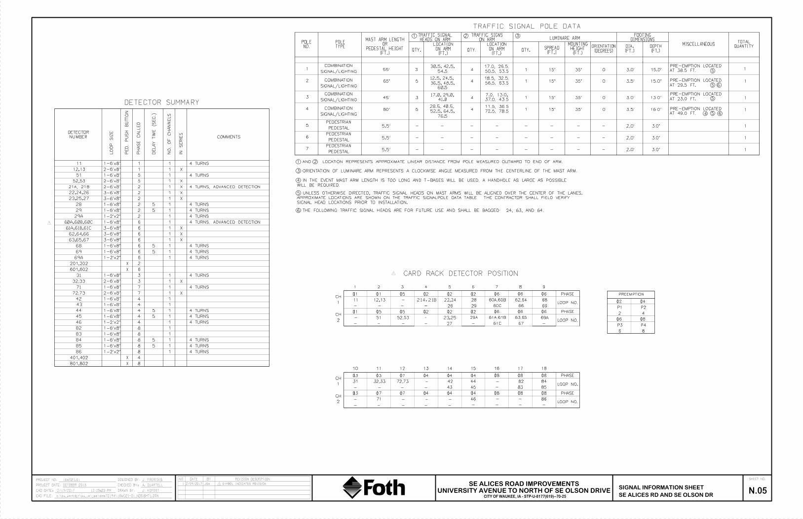
SE ALICES RD AND SE OLSON DR
DETECTOR SUMMARY
PE
D.
PU
SH
BU
TT
ON
PH
AS
E
CA
LLE
D
DE
LA
Y
TIM
E (S
EC.)
NO.
OF
CH
AN
NE
LS
LO
OP
SIZ
E
1
NUMBER
DETECTOR
1
COMMENTS
1
2
6
1
1
1551
1
6
2
6
2
6
1
IN
SE
RIE
S
X
TRAFFIC SIGNAL POLE DATA
NO.POLE
TYPEPOLE
(FT.)PEDESTAL HEIGHT
ORMAST ARM LENGTH
QTY.
LUMINARE ARM
(FT.)ON ARM
LOCATION
(FT.)SPREAD
(FT.)HEIGHT
MOUNTING
(DEGREES)ORIENTATION
DIMENSIONSFOOTING
(FT.)DIA.
(FT.)DEPTH
MISCELLANEOUSQUANTITY
TOTAL
1
4 15' 35' 0
1
1
1 2
SIGNAL/LIGHTING
COMBINATION
3SIGNAL/LIGHTING
COMBINATION1
15' 35' 0
QTY.
2
SIGNAL/LIGHTING
COMBINATION 15' 35' 0 1
1
1
1
HEADS ON ARMTRAFFIC SIGNAL
ON ARMTRAFFIC SIGNS
QTY.(FT.)
ON ARMLOCATION
1 AND 2 LOCATION REPRESENTS APPROXIMATE LINEAR DISTANCE FROM POLE MEASURED OUTWARD TO END OF ARM.
15' 35' 01
3.5'
3.5'
11
201,202
4
4
4
1
1
8
401,402
801,802
1-6'x8'
1-6'x8'
1-6'x8'
3-6'x8'
X
X
X
X
1
1
X
X
4 TURNS
4 TURNS
4 TURNS
CARD RACK DETECTOR POSITION
01 02 02 06
1 2 3 4 5 6 7 8
1
CH
2
CH
01 05 02 06
02 02 0601 05 02 06
03 04 04 08
10 11 12 13 14 15 16 17
1
CH
2
CH
03 07 04 08
07 04 0803 04 0407
11
- -
---
- - --
- - -
-
- - -
0402
0806
P2
42
P4P3
86
PREEMPTION
12,13
52,53
PHASE
LOOP NO.
PHASE
LOOP NO.
PHASE
LOOP NO.
PHASE
LOOP NO.
06
9
06
08
18
08
-
-
4 1 4 TURNS
-
2 1
55'
45'
3
29
6 1
42
44
22,24
29
61C
62,64
69
31
-
-
71
-
- - -
05
51
-
- 27
26
23,25
28
61A,61B
66
63,65
67
68
12,13 2-6'x8'
5 1 X2-6'x8'52,53
2-6'x8'
22,24,26
2 1 X23,25,27
1-6'x8'
2 1 4 TURNS28 1-6'x8'
3-6'x8'
3-6'x8'
2 129A 1-2'x2'
61A,61B,61C 3-6'x8' X
62,64,66 3-6'x8'
63,65,67 X
1 4 TURNS69 1-6'x8'
1 4 TURNS68 1-6'x8'
169A 1-2'x2'
6
6
6
601,602
69A29A
5
47.0, 13.0,
SIGNAL INFORMATION SHEETN.05
32,33
46
08
86
-
-
-
-
3 131
3 1 X
8 182
8 183
8 184
8 185
8 186
43
1-6'x8'
1-6'x8'
4 1 4 TURNS45
4 1 4 TURNS46
1-6'x8'
1-6'x8'
32,33
1-6'x8'
2-6'x8'
4 TURNS
1-2'x2'
1-2'x2'
1-6'x8'
1-6'x8'
1-6'x8'
1-6'x8'
4 TURNS
4 TURNS
4 TURNS
7 171
7 1 X72,73
1-6'x8'
2-6'x8'
4 TURNS
65'
80'
5
3
5
17.0, 29.0,
41.0
4
17.0, 26.5,30.5, 42.5,
54.5
12.5, 24.5,
36.5, 48.5,
60.5
AT 38.5 FT.
PRE-EMPTION LOCATED
AT 29.5 FT.
PRE-EMPTION LOCATED
AT 23.0 FT.
PRE-EMPTION LOCATED
AT 49.0 FT.
PRE-EMPTION LOCATED
5
6
7
SIGNAL/LIGHTING
COMBINATION
PEDESTAL
PEDESTRIAN
PEDESTAL
PEDESTRIAN
PEDESTAL
PEDESTRIAN
5.5'
5.5'
5.5'
-
-
-
- - - - - -
- - - - - -
- - - - - -
3.0'2.0'
16.0'
13.0'
15.0'
15.0'
2.0' 3.0'
2.0' 3.0'
1
1
1
3 ORIENTATION OF LUMINARE ARM REPRESENTS A CLOCKWISE ANGLE MEASURED FROM THE CENTERLINE OF THE MAST ARM.
3
SIGNAL HEAD LOCATIONS PRIOR TO INSTALLATION.
APPROXIMATE LOCATIONS ARE SHOWN ON THE TRAFFIC SIGNALPOLE DATA TABLE. THE CONTRACTOR SHALL FIELD VERIFY
5 UNLESS OTHERWISE DIRECTED, TRAFFIC SIGNAL HEADS ON MAST ARMS WILL BE ALIGNED OVER THE CENTER OF THE LANES.
WILL BE REQUIRED.
4 IN THE EVENT MAST ARM LENGTH IS TOO LONG AND T-BASES WILL BE USED, A HANDHOLE AS LARGE AS POSSIBLE
5
5
5
6
-
-
-
28.5, 40.5,
52.5, 64.5,
76.5
411.5, 36.5
18.5, 32.5,
4 TURNS
4 TURNS
4 TURNS, ADVANCED DETECTION
4 TURNS, ADVANCED DETECTION
5
5
5
5
5
5
5
5
4
6
6 THE FOLLOWING TRAFFIC SIGNAL HEADS ARE FOR FUTURE USE AND SHALL BE BAGGED: 24, 63, AND 64.
-
72,73
-
42
43 45
44 82
83
84
85
-
4 50.5, 53.5
56.5, 63.5
37.0, 43.5
72.5, 78.5
21A, 21B X
3.0'
3.0'
21A,21B
- -
60C
60A,60B
60A,60B,60C
1 2/09/2017 JSW SYMBOL INDICATES REVISION1
1
1
P1
SHEET NO.REVISION DESCRIPTIONBYDATENO
CAD FILE:
CAD DATE:
PROJECT DATE:
PROJECT NO:
c:\pw_workdir\pw_ie\jae\dms70194\16W021-01_N05.SHT1.DGN
2/13/2017 12:15:23 PM
DESIGNED BY:
CHECKED BY:
DRAWN BY: J. KOFOOT
A. QUARTELL
J. FRERICKS
UNIVERSITY AVENUE TO NORTH OF SE OLSON DRIVE
SE ALICES ROAD IMPROVEMENTS
CITY OF WAUKEE, IA - STP-U-8177(619)--70-25
16W021.01
OCTOBER 2016

SE ALICES RD AND SE OLSON DRN.08
SIGNAL DETAILS SHEET
SHEET 1 of 1
MODIFIED
1
CURB
OF THROUGH TRAFFIC.
PERPENDICULAR TO PATH
ROTATED 30" FORM A LINE
LOCATE LOOP WITH EDGE
TH
RO
UG
H T
RA
FFIC
1
18"
2'
2'
2" DIA. DRILLED HOLES
DETECTOR
RIGHT TURN COUNT
1 2/10/2017 JSW ADDED 12 SM SPLICE DIAGRAM
SHEET NO.REVISION DESCRIPTIONBYDATENO
CAD FILE:
CAD DATE:
PROJECT DATE:
PROJECT NO:
c:\pw_workdir\pw_ie\jae\dms70194\16W021-01_N08 W Addendum1.SHT.DGN
2/13/2017 12:15:40 PM
DESIGNED BY:
CHECKED BY:
DRAWN BY: J. KOFOOT
A. QUARTELL
J. FRERICKS
UNIVERSITY AVENUE TO NORTH OF SE OLSON DRIVE
SE ALICES ROAD IMPROVEMENTS
CITY OF WAUKEE, IA - STP-U-8177(619)--70-25
16W021.01
OCTOBER 2016

Checks (EW-102) TopsoilFill
224220+00.00
152 72 38
118
34190 146 41
Approx. Fill
Volume Below 3'
Cu. Yds.
Total
Topsoil Cut
Volume
20 6 8
219+00.00209 128
219+50.00
[1] [2] [3] [4] [5] [6]
30 39
218+50.00241 153
Cut
38 180
4759 4
220 142
107-2804-21-15
[10] [11] [22][7] [12] [13] [14]
Refer to Standard Road Plans EW-101 and EW-102. TABULATION OF TEMPLATE QUANTITIES AND ADJUSTMENTS
Station
Template Cut
Volume
Template
Class 10
Volume
217+50.00137 104 33 59 163 125 20
82
Alices Rd Stage 199
Template Fill
Volume
93 2839
Topsoil
Stripping
+ Fill
38 28 6569
Add
Quantity
+Fill
Total
Fill
Adjusted
Total Cut Adjusted
w/ 1.3 Shrink
Factor Minus Fill
Approx. Fill
Volume Below
5' And Above 20'
Cu. Yds.
Template
Topsoil Cut
Volume
Template
Rock Undercut
Volume
[9]
59
Total
Cut
Adjusted
Total Cut
Adjusted w/
Weighted Average
1.3 Shrink Factor
30
Template
Topsoil
Replacement
Volume
Topsoil Cut
With
1.5 Shrink
Factor
[21][17] [18] [19] [20][15][8]
108
12
218+00.00214 154
20
26
54166
88
105121
81
[16]
59 80 234 180 10
8178 17 52
212 163 540
00 65
217+00.00
8 33120
209 266
17
4747
12
57
083
123
Topsoil Cut
With Shrink
Minus Topsoil
Replacement
57
220 14 38
72 14
16040
0
0 3980
088
3659
3580 48 19 5441
123 0 13 64 10 43 33
101 62
151 2841 105 0 26
8438
138 54 35
28
128
48
0 77 10 52197 152 14
1380 76
01239 51
67 8 45221+50.00
235 159162 67 38
222+50.00187 106 81
422
1
15 137 037
72 35 12 47223+50.00
15
200 154 17 1
14180
5025 0
136 076 38
86
224+00.0087 7 54
1 42
221+00.00229
222+00.00220 143 77 37
220+50.00222 158 64 38
79 63 70
196
93
78
37 143 110 16 7 23 45223+00.00
142 56 86 3798 23 75 58 81 62 39 12 51 0
8 5846
87 0 81 9 54
47
21
205 106 19 71
31 75 4 50
5253
11
225+00.00163 41 123 29 82123 37 78 60 217
101 13 114 -60 0 99 79 6224+50.00
42 214 12 226106 42 -184 0
225+50.00
70 -63 0
55119 13
62 223 13 23653
168 42
50
12
226+00.00116 17
80 84300288 22 5
226+50.0024 2 7 9 7 67119
226+90.82
99 31 48 37 257 11
2999 38
54
10
-174229 -169 0 203
105 19
99 22 66 4422
76 52
28837 37 28 317 13
5 114 38
99
43 33 354 13
0 38106 0 330
275 99 16
3268 -231 0
227+50.00227+00.00
301 -27299 57
0 210 126 30
367 -334 0 62 114 24
6666
126 38
256
-302 0
15
2685950
8175 100100 8 67
303 105 70 51
183 13 196 -150 080 62 175 13
241 99 1613
58 450
0 167188 -126-223 0
15 66 5123067 59
228+50.00104
-152 099
14-200 0 203
229+00.00103 3 100 57 60 46
12100 14 100 76
228+00.00
100 1 99230+00.00
98 2 96 38 12 183230+50.00
96 1231+00.00
102 7231+50.00
104 9
39 3040 31 171
229+50.0038
13 64 5195 38
96 40
157 96
44 34 177 1395 37 -156 0 163 95182 12
50
51167 -129 0 142
39 30
13 64
168 95
49 38 157 10190
96
13 64 51
5 192 -154 66
194 -164 064
217 13
232+00.00103 4
232+50.00107 4
234+50.00154 29
234+00.0091
375 -333 0 361 106 18 71 53
125 41
233+00.00112 6 106
25 66 67
233+50.00114 6
250 -210 0 234 103 165245 49 38 187 0 172 99 14
92 71 66 11 44 33
1
0
69
42 489 489 -447 0 475260 260
235+00.0027 27
236+00.009 117
0 67 52 00
235+50.00112 3 109 39
-189
103 48 52 40
108 49 55 72 51
5349 55 42 374
99
7180 726 117
248 2
108
59 342
70 54
21
12 00
125 0 84 840 119
42 32
253
73-686 00
235+25.0017 17 0 60 77
236+50.00
342 -283706
40
7146
0
119 -65 00 52 0 0 0 0 0
-12168 0109
738 -7034528
37 33 78 45718
113 6 106 37 43 33 686 686126 35 738
42
5,681 2,082
0 0 0 0 319 0 0 0237+00.00
0 0 0 0 0 0-653 0 676 106 29
28 523 89 0
8,530 -5,469 0
Alices Rd Stage 2119 91 28 54 145 112 23
237+50.00
Subtotals:0 7,7123,597 1,897 3,979 3,061 8,068 462
0
3,597 599 2,407 1,808
12 246 0
25 52 164 126 10819 14
0 25 5 17 12
221 124 336 258 12
18 18217+00.00
218+00.00256 197 15
0217+50.00
187 164 24 92137 112
218+50.00207
104 1421192
233 21215 182 0 0 24 4 16 12
10
0 018 154 0 0
170 21 51 221 170 1818
167 25 50 217 167
2110
0 1
220+00.0021 4 14
192
191219+50.00
37 126 0 19190 161
154 14 10
30
21 4 14186 21 83 269 207 15
30
195 174 21 50 224 17218 152
1021 4 14
219+00.00182 161 21 51 212 163 18 145 0
220+50.0030 137 0 12 25 5 17 12
222+00.00
221+00.00
018
51 212 163 3730
4484
147 45 51 198 152 310
45 4 3020
89
31
221+50.00198
222+50.00168 112 55 51 163 125 51
2537 51 212 163 27161121 0 12
6 20 14
56
19237 32
153 118 41
33
41 77 0 32 53 4 36 3276
3751 74
6464
83 109 60 128 64 6 43 37
27 136 0 9 37 526
43 37109 -26 0 91 64
7223+50.00
121 68 53
64 6
224+00.00116 64 53
224+50.00109 44 64 64 108
43 37
225+00.0097 34
225+50.0097 33
14 032
147 -8251 84 65 144 144 -79 051
0 45 53 4 3665 65
226+00.00
223+00.00140 76 65 51 127 98 84
85 65 147124
144 111 55 55
55 5
CAD FILE:
PROJECT NO:
2/15/2017 5:42 PM DRAWN BY: J. KOFOOT
EARTHWORK QUANTITY SHEETSCITY OF WAUKEE, IA-STP-U-8177(619)--70-25c:\pw_workdir\pw_ie\jcd\dms82998\Addendum1-0016W021.01_T01_SHT.xlsm
SHEET NO.16W021-01 DESIGNED BY: J. FRERICKS NO DATE BY REVISION DESCRIPTIONSE ALICES ROAD IMPROVEMENTS
OCTOBER 2016 CHECKED BY: A. QUARTELLSE ALICES ROAD
T.1UNIVERSITY AVENUE TO NORTH OF SE OLSON DRIVE
PROJECT DATE:
CAD DATE:

Checks (EW-102) TopsoilCut Fill
EARTHWORK QUANTITY SHEETSCAD FILE: c:\pw_workdir\pw_ie\jcd\dms82998\Addendum1-0016W021.01_T01_SHT.xlsm
SHEET NO.PROJECT NO: 16W021-01 DESIGNED BY: J. FRERICKS NO DATE BY REVISION DESCRIPTION PROJECT DATE: OCTOBER 2016 CHECKED BY: A. QUARTELL SE ALICES ROAD
T.2CAD DATE: 2/15/2017 5:42 PM DRAWN BY: J. KOFOOT
504+50.0022 2 20 9 11 8 27 27 -19 0 43 20 1 14 13
504+75.00
9 15504+00.00
25 6 1910
504+38.3139 6 33 17 23 18 50 50 -32 0 20 33 3 22 19
504+25.0021 5 16 8 13 10 23 23 -13 0 24 16 1 11
12 28 28 -16 0 49 19 1 13 12
Future Rd40 6 34 33 39 30 60 60 -30 0 0 34 4 23 19
Subtotals:298 1,084 833 117 40 0 157 676 0 0 208 38 142
706+00.00
996 786 208
705+75.000 0 0 0 0 0 0 0 0 0 0 0 0 0 0
104
19 67705+00.00
64 48 167
705+50.0038 27 10 16 43 33 8 3 11 22 0 0 10 2 7 5
705+25.0049 36 13 18 54 42 8 2 10 32 0 0 13 2 9
52 8 2 10 42 0 0 16 3 11
3 10 7
8
704+75.0076 58 18 20 78 60 8 2 10 50 0 0 18 3 12 9
7703+25.00
388 328 60 98 426 328 38 3 41 287 0 0 60 14 40 26703+50.00
77 62
703+00.0071 57 14 19 76 58 8 2 10 48 0 0 14
19 56
15 20 82 63 8 1 9 54 0 0 15
3 1043 9 5 14 29 0 0 16 3 11 8
702+50.0048 32 16 19 51 39 9 4 13 26 0 0 16 3 11 8
702+75.0053 37 16
702+34.5850 36 14 19 55 42 8 2 10 32 0 0 14 2 10 8
11 33Private Dr
38 22 160
702+25.0026 25 0 12 37 28 2 2 26 0 0 0 0 0 0
702+09.6218 18 0 8 26 20 0 0 20 0 0 0 0 0
25 3 14 17 8 0 0 16 0 11 11
303Subtotals:
753 306 449 0 306 233 478 7 0 485 -252 0 382 449 0 303
1239+25.000 0 0 0 0 0 0 0 0 0 3 0 0 0 0
1239+50.00
1239+00.0056 37 19 0 37 28 4 7 11 17 0 4 19 0 13 13
0 331238+25.00
93 33 6029
1238+75.0085 59 27 0 59 45 7 7 38 0 6 27 0 18 18
1238+50.0080 37 43 0 37 28 33 33 -5 0 33 43 0 29
25 60 60 -35 0 59 60 0 40
0 46 46
40
1238+00.0096 31 65 0 31 24 67 67 -43 0 66 65 0 44 44
491237+50.00
104 34 71 0 34 26 95 95 -69 0 95 71 0 48 481237+75.00
98 30
1237+40.85111 37 73 0 37 28 103 103 -75 0 37 73
0 8
68 0 30 23 79 79 -56 0 79 68
0 496 30 30 -24 0 0 23 0 16 16
Alices Transition30 8 23
237+50.00
1,081Subtotals:
7,597 5,606 1,993 2,563 8,169 6,283 3,237 144 0 3,381 2,902 0 2,850 1,993 261 1,342
25 67 42237+00.00
0 0 0 0 0 0 0 0 0 0 348 0 0 0 0
35236+00.00
91 0 91 62 62 48 540 540 -492 0 527 91 22 61 39236+50.00
100 0
235+50.0077 0 77 62 62 48 364 364 -316 0 351 77
82 108
100 56 56 43 642 642 -599 0 632 100
17 5283 114 114 -31 0 54 0 7 0 -7
235+00.0032 32 0 51 83 64 0 0 64 0 0 0 0 0 0
235+25.0026 26 0
234+50.0043 43 0 53 96 74 0 0 74 0 0 0 0 0 0
56 7 38233+00.00
196 140 5627
234+00.00256 91 165 84 175 135 13 144 157 -22 0 4 165 2 110 108
256 203
233+50.00148 100 48 54 154 118 29 29 89 0 11 48 5 32
147 32 32 115 0 12244 187 57 51 238 183 29 29 154 0 10 57 7 38 31
232+00.00
51 191
53 51 254 195 25 25 170 0 6 53 7 36 29
31
232+50.00
19 187 0 0 59 4 40 363121 189 0 1 55 6 37
23 179 24260 211 48 51 262 202 23
231+00.00277 222 55 51 273 210 21
231+50.00
59 50 268 206 19
0 4 48 8 32
230+00.00280 220 60 50 270 208 19 19 189 0 0 60 4 40 36
230+50.00277 218
274 211 19 19 192 0 0 56 5 38 33
229+00.00233 201 32 76 277 213 10 10 203 0 0 32 3 22 19
229+50.00279 223 56 51
234 29 103 337 259 8 8 251 0 0 29 5 20 15
46 38228+00.00
274 219 55 78 297 228 46 46 182 0 28 55 8 37 29228+50.00
263
144 144 -28 0 125 71 10 48 38227+50.00
201 134 68 51 185 142 101 101 41 0 81 68 8
226+90.82273 230 43 51 281 216 86 86 130 0 14 43 6 29 23
227+00.00172 100 71 51 151 116
9 78 60 2 2 58 0 7 2 0 2 2
Station
Template Cut
Volume
Template
Class 10
Volume
Template
Topsoil Cut
Volume
Template
Rock Undercut
Volume
Total
Cut
Adjusted
Total Cut
Adjusted w/
Weighted Average
1.3 Shrink Factor
Template Fill
Volume
Topsoil
Stripping
+ Fill
Add
Quantity
+Fill
Total
Fill
Adjusted
Total Cut Adjusted
w/ 1.3 Shrink
Factor Minus Fill
Approx. Fill
Volume Below
5' And Above 20'
Cu. Yds.
Approx. Fill
Volume Below 3'
Cu. Yds.
Total
Topsoil Cut
Volume
Template
Topsoil
Replacement
Volume
Topsoil Cut
With
1.5 Shrink
Factor
Topsoil Cut
With Shrink
Minus Topsoil
Replacement
226+50.0071 69 2
[6] [7] [8] [9] [10] [11] [12] [13] [14] [15] [16] [17] [18] [19] [20] [21] [22]
Refer to Standard Road Plans EW-101 and EW-102. TABULATION OF TEMPLATE QUANTITIES AND ADJUSTMENTS 107-2804-21-15
[1] [2] [3] [4] [5]

Checks (EW-102) TopsoilFill
0
CHECKED BY: A. QUARTELL SE ALICES ROAD
T.3CAD DATE: 2/15/2017 5:42 PM DRAWN BY: J. KOFOOT
EARTHWORK QUANTITY SHEETSCAD FILE: c:\pw_workdir\pw_ie\jcd\dms82998\Addendum1-0016W021.01_T01_SHT.xlsm
[17] [18] [19] [20]
Cut
Refer to Standard Road Plans EW-101 and EW-102. TABULATION OF TEMPLATE QUANTITIES AND ADJUSTMENTS 107-2804-21-15
[10] [11] [12] [13] [14] [15] [16]
2008+50.00
24
SHEET NO.PROJECT NO: 16W021-01 DESIGNED BY: J. FRERICKS NO DATE BY REVISION DESCRIPTION PROJECT DATE: OCTOBER 2016
9
2008+25.00132 113 20 0 113 87 0 24 24 63 0 0 20 8 14 6
0 10172 132 0
192008+00.00
196 172 25 25 107 0 0 24 9 16 7
2007+25.00399 366 33
2007+75.00258 230 28 0 230 177 0 15 15 162
9
15 96
8
0332 301 31 0 301 232 0 14 14 218 0 0 31 12 21
28
282 0 14 14 268 0 0 33 14 222007+50.00
0 366
39 0 377 290 0 11 11 279 0 0 39 20 262007+00.00
444 409 35 0 409 315 0 11 11 304 0 0 35 24
Trail E of Alice416 377
2,096 1,842 255 0 1,842 1,419 7 2 220 229 1,190 0 4 255 85 173 88Subtotals:
2005+00.00
0 3662004+25.00
398 366 339
2004+75.000 0 0 0 0 0 0 0 0 0 0 0 0 0 0
2004+50.00403 370 33 0 370 285 0 20 20 265 0 0 33 13 22
282 0 20 20 262 0 0 33 13 22
11 19 8
9
2004+00.00355 325 30 0 325 250 0 26 26 224 0 0 30 12 20 8
82003+50.00
229 203 26 0 203 156 0 26 26 130 0 0 26 9 18 92003+75.00
294 266
2003+25.00175 152 23 0 152 117 0 38 38 79 0 0 23
0 97
28 0 266 205 0 26 26 179 0 0 28
8 1675 0 35 35 40 0 0 21 6 14 8
2002+75.0066 47 19 0 47 36 0 29 29 7 0 0 19 4 13 9
2003+00.00118 97 21
2002+50.0029 14 14 0 14 11 0 0 11 0 0 14 3 10 7
0 0Trail W of Alice
9 0 94
2002+25.0011 2 10 0 2 2 2 2 0 0 1 10 2 7 5
2002+00.009 0 9 0 0 0 3 3 -3 0 3 9 2 6
0 2 2 4 -4 0 0 9 2 6 4
286Subtotals:
1,995 1,268 725 621 1,889 1,454 589 2 0 591 863 0 481 725 205 491
106+75.000 0 0 0 0 0 0 0 0 0 31 0 0 0 0
107+00.00
106+50.0079 34 45 25 59 45 71 71 -26 0 63 45 19 30 11
30 71104+50.00
75 41 3412
106+25.0075 34 40 25 59 45 59 59 -14 0 51 40 16 27 11
106+00.0072 37 35 26 63 48 44 44 4 0 37 35 12 24
55 35 35 20 0 166 34 8 23
10 25 15
15
104+25.00600 383 217 201 584 449 167 167 282 0 20 217 42 145 103
10103+75.00
99 67 32 26 93 72 22 22 50 0 14 32 10 22 12104+00.00
112 76
103+50.0096 67 29 25 92 71 22 22 49 0 14 29
25 94
37 30 106 82 25 25 57 0 16 37
10 2072 17 17 55 0 9 28 10 19 9
103+00.0098 69 28 25 94 72 17 17 55 0 9 28 10 19 9
103+25.0097 69 28
102+89.0490 68 22 25 93 72 15 15 57 0 4 22 9 15 6
25 84102+25.00
91 59 314
102+75.0036 29 7 11 40 31 6 6 25 0 4 7 3 5 2
102+50.0048 35 13 14 49 38 7 7 31 0 8 13 5 9
65 14 1 15 50 0 8 31 8 21
5 17 12
13
102+00.0085 55 29 24 79 61 15 1 16 45 0 6 29 7 20 13
10101+50.00
64 39 26 21 60 46 13 13 33 0 7 26 7 18 11101+75.00
74 48
101+25.0055 31 25 21 52 40 13 13 27 0 8 25
19 46
25 23 71 55 14 14 41 0 6 25
7 1735 13 13 22 0 0 22 7 15 8
SE Olson Dr49 27 22
25Subtotals:
305+00.000 0 0 0 0 0 0 0 0
384 306 77 80 386 296 52 0 0 52 244 0 4 77 28 53
304+50.00135 23 16 128 98 11 23 8 16 8
304+75.000 0 0 0 0 0
4
11 87 0 0
304+25.0094 78 15 16 94 72 10 10 62 0 0 15 5 10 5
112
304+00.0067 54 13 16 70 54 9 9 45 0 1 13
16 525 9
40 10 10 30 0 3 13 5 9 4
SE Frontier Ave39 26 13 16 42 32 12 12 20 0 0 13 5 9 4
303+75.0049 36 13
Subtotals:101 264 0 0 264 -163 0 207 181 14 123103 131210
505+25.000 0 0 0 0 0 0 26 0 0 0 00 0
10928 181
Topsoil Cut
With Shrink
Minus Topsoil
Replacement
504+88.7643 2 40 20 22 17 55 55 -38 0 22 40 3 27 24
505+00.000
Station
Template Cut
Volume
Template
Class 10
Volume
Template
Topsoil Cut
Volume
Template
Rock Undercut
Volume
Total
Cut
Adjusted
Total Cut
Adjusted w/
Weighted Average
1.3 Shrink Factor
Template Fill
Volume
Topsoil
Stripping
+ Fill
Add
Quantity
+Fill
Total
Fill
Adjusted
Total Cut Adjusted
w/ 1.3 Shrink
Factor Minus Fill
[1] [2] [3]
Template
Topsoil
Replacement
Volume
Topsoil Cut
With
1.5 Shrink
Factor
Approx. Fill
Volume Below
5' And Above 20'
Cu. Yds.
Approx. Fill
Volume Below 3'
Cu. Yds.
Total
Topsoil Cut
Volume
[21] [22][4] [5] [6] [7] [8] [9]

Checks (EW-102) TopsoilCut Fill
107-2804-21-15
Refer to Standard Road Plans EW-101 and EW-102. TABULATION OF TEMPLATE QUANTITIES AND ADJUSTMENTS
[1] [2] [3] [4] [5] [6] [7] [8] [9] [10] [11] [12] [13] [14] [15] [16] [17] [18] [19] [20] [21] [22]
Station
Template Cut
Volume
Template
Class 10
Volume
Template
Topsoil Cut
Volume
Template
Rock Undercut
Volume
Total
Cut
Adjusted
Total Cut
Adjusted w/
Weighted Average
1.3 Shrink Factor
Template Fill
Volume
Topsoil
Stripping
+ Fill
Add
Quantity
+Fill
Total
Fill
Adjusted
Total Cut Adjusted
w/ 1.3 Shrink
Factor Minus Fill
Approx. Fill
Volume Below
5' And Above 20'
Cu. Yds.
Approx. Fill
Volume Below 3'
Cu. Yds.
Total
Topsoil Cut
Volume
Template
Topsoil
Replacement
Volume
Topsoil Cut
With
1.5 Shrink
Factor
Topsoil Cut
With Shrink
Minus Topsoil
Replacement
2008+75.0024 12 12 0 12 9 0 0 9 0 0 12 4 8 4
2009+00.0011 1 10 0 1 1 1 1 0 0 0 10 3 7 4
2009+25.009 0 9 0 0 0 3 3 -3 0 3 9 2 6 4
2009+50.009 0 9 0 0 0 4 4 -4 0 3 9 2 6 4
2009+75.000 0 0 0 0 0 0 0 0 0 1 0 0 0 0
2010+00.00
2,297 2,031 266 0 2,031 1,563 8 0 122 130 1,433 0 7 266 105 180 75Subtotals:
22,009 14,255 7,751 5,562 19,817 15,243 12,820 657 342 13,819 1,424 11,647 7,751 1,335 5,214 3,879Project Totals:
EARTHWORK QUANTITY SHEETSCAD FILE: c:\pw_workdir\pw_ie\jcd\dms82998\Addendum1-0016W021.01_T01_SHT.xlsm
SHEET NO.PROJECT NO: 16W021-01 DESIGNED BY: J. FRERICKS NO DATE BY REVISION DESCRIPTION
SE ALICES ROAD
T.4CAD DATE: 2/15/2017 5:42 PM DRAWN BY: J. KOFOOT
PROJECT DATE: OCTOBER 2016 CHECKED BY: A. QUARTELL