investigation of the june 6, 1994 collapse of a radio
TRANSCRIPT

INVESTIGATION OF THE JUNE 6, 1994 COLLAPSE OF A RADIO TOWER IN SELMA, ALABAMA _____________________________________________________________________________________ U.S. Department of Labor Occupational Safety and Health Administration
October 1994

Material contained in this publication is in the public domain and may be reproduced, fully or partially, without permission of the Federal Government. Source credit is requested but not required.
This information will be made available to sensory impaired individuals upon request. Voice phone: (202) 219-8259 TDD message referral phone: 1-800-326-2577

INVESTIGATION OF THE JUNE 6, 1994 COLLAPSE OF A RADIO TOWER IN SELMA, ALABAMA
U.S. Department of Labor Robert B. Reich, Secretary
Occupational Safety and Health Administration Joseph A. Dear, Assistant Secretary
1 Office of Construction and Engineering Russell B. Swanson, Director
Mohammad Ayub, P.E. Fragrance Liu, P.E.
October 1994
1

TABLE OF CONTENTS
INTRODUCTION 1
1.0 DESCRIPTION OF THE PROJECT AND THE ACCIDENT . . . . . . . . . . . . . . . 2
2.0 FIELD OBSERVATION OF THE FAILED STRUCTURE. . . . . . . . . . . . . . . . . 9
3.0 STRUCTURAL ANALYSIS AND DISCUSSION 18
4.0 CONCLUSIONS. . . . . . . . . . . . . . . . . . . . . . . . . . . . . . . . . . . . . . . . . .. 30
Appendix-A
Computations
)

INTRODUCTION )
A 350' high guyed radio transmission tower collapsed during the final phases of its construction on June 6, 1994 at approximately 9:00 AM in Sehna, Alabama. The tower structure consisted of twenty-five pre-fabricated steel sections, each 10 or 20 ft in height. The erection of the tower sections started on May 20 and was completed on May 23, 1994.
) A masonry building was then constructed about 10 ft north of the tower to house the electrical equipment needed for the radio transmission. On June 3, 1994, three FM antennas were hoisted and fastened to the top sections of the tower using a new position of the snatch block located above the roof of the electrical equipment building. Prior to the construction of the electrical equipment building, the snatch block was positioned at the base of the structure during the erection of the tower sections. On the morning of June 6, two workers positioned near the top section of the tower, having completed the fastening of the coaxial cable to the top section of the tower, were beginning to lower the erection gin pole from the top section of the tower to the ground. The gin pole suddenly dropped and struck the coaxial cable, followed by the collapse of the tower structure. See Figure 1.4. Both workers, who were tied to the collapsing tower, fell to the ground. The accident resulted in the death of one worker and serious injuries to the other.
The compliance officer from the Occupational Safety And Health Administration (OSHA)'s Mobile Area Office arrived at the construction site on the following morning to gather information relating to the activities preceding the accident. The compliance officer took photographs of the accident site and the collapsed tower sections, interviewed workers and the owners of the tower erection company and the radio station. The Office of Construction and Engineering, OSHA National Office in Washington DC, was requested by the OSHA Regional Office, Atlanta, GA to provide assistance to the Area Office in the investigation of the accident. Structural Engineers from the Office of Construction and Engineering visited the accident site on June 8, 9, and on June 26, 1994 to examine the collapsed structure, take necessary measurements of the tower sections, obtain pertinent information about the fabrication and design of the tower section and to interview the personnel of the tower erection company.
The OSHA investigation included eyewitness accounts, interviews of the construction workers, review of the tower erection procedure, observation of the collapsed structure and engineering calculations. Throughout the course of the investigation, the Office of Construction and Engineering worked together with the Mobile Area Office, whose contributions are hereby acknowledged.
1

)
)
)
1.0 DESCRIPTION OF THE PROJEO AND THE ACCIDENT
The structure under construction in Selma, Alabama was a 350 feet high guyed radio transmission tower. A tower company (hereafter called the contractor) was contracted by the owner of the radio station to furnish and erect the tower. The contractor proposed to use fifteen new 10' high sections bought from a nationally known tower manufacturing company and ten old sections salvaged from two towers demolished earlier at other locations. The new and used tower sections were delivered to the job site on May 17, 1994.
The contractor also furnished other construction materials, e.g. gin poles, guywires, anchors, lighting kits, beacons, and sidelights [see Appendix A- Contract Agreement]. The contractor stated that the radio tower structure was not designed by a professional engineer. He, however, claimed that the assembly of the tower was accomplished as per construction details contained in the ROHN's commercial product catalog for a 350' high tower.
The bottom 80 ft of the tower consisted of four 20' high tower sections salvaged from a 330' high old tower demolished sometime back by the contractor at a different location. The vertical and horizontal members consisted of steel pipes. The diagonals were square solid bars. The tower sections were triangular in plan, each side equal to 18".
The middle 120 ft of the tower consisted of six 20' high tower sections, also salvaged from an old radio tower which was acquired by the contractor in November 1993. All members of the section consisted of solid square bars. See Figure 1.1. The middle sections were also triangular in plan, each side being 18".
The upper 150 ft of the tower consisted of fifteen new 10' high sections manufactured by ROHN co. The vertical members consisted of steel pipe sections, while the horizontal and diagonal members were solid square bars. The ROHN tower sections were also triangular in plan, each side being equal to 17". See Figure 1.1.
The tower was guyed at eight levels at approximate elevations of 50', 75', 100', 150', 200', 250', 290', and 350' above the base. At each level, there were three guy wires, 120 degrees apart. The guywire cables at the upper four levels were 5/16" in diameter and were anchored to a steel plate/rod assembly embedded in a concrete foundation located approximately 280 ft from the tower base (identified as the outer anchor). The guywire cables at the lower four levels were 1/4" in diameter and were attached to a similar steel plate/rod assembly anchored into a concrete foundation located at about 100 feet from the base (identified as the inner anchor). See Figure 1.2. Field observation of the failed tower structure confirmed the location of the guywire cables at the approximate elevations mentioned above. The inground anchor locations were also verified by a survey company.
2

)
)
)
}
J
See Figure 1.3. A local engineering finn, contracted by the Mobile Area Office, conducted the site survey a few days after the accident. See Figure 1.4 for the collapsed tower structure.
The tower section was erected employing a gin pole and double drum hoists system. This erection method is commonly used by the construction companies for these types of towers. The lower 80 ft of the tower was assembled on the ground and positioned on the concrete slab foundation by a crane. The guywire cables were installed and tensioned. A gin pole was then raised to the top of the structure by a hoist line from the winch truck through a snatch block located near the bottom of the tower. The winch truck was located at the north of the tower structure. After being hoisted to the proper elevation, the gin pole was fastened to the tower legs with wire rope/hook at its middle and bottom locations. Guided with a tag line, each tower section was then raised and placed atop of the previously erected section using the winch truck's second hoist line through the tower base snatch block. Figure 1.5 is a schematic view of the erection procedure. Two workers at the top of the tower aligned and bolted the newly placed tower section to the lower one. The gin pole was then detached, hoisted to the next higher elevation, and re-fastened to the tower for setting the next section. The above erection procedure was followed until the tower was completed. Guywires were installed at the specified locations and were tensioned to approximately 10 percent of their ultimate breaking strength.
The erection of the tower sections began on May 20 and was completed on May 23, 1994. Following the completion of the tower, a masonry building 10' X 11' in plan was constructed to house the electrical equipment approximately 10 ft north of the tower. When the work on the tower resumed on June 3, 1994, the foreman decided to reposition the snatch block at an elevation of approximately 22 feet above the base to clear the height of the equipment building. The snatch block was needed to hoist the antennas and co-axial cable. The antennas were then hoisted and placed in position and fastened to the tower. On the morning of June 6, 1994, two workers climbed to the tower top, made final adjustments to the antenna, and completed the hoisting of approximately 350 ft coaxial cable to the top. After tieing the top end of the cable to the tower leg, the workers were beginning to lower the gin pole. It was reported that the gin pole then suddenly slipped approximately 3 ft downward, struck the coaxial cable, and then the tower collapsed. The accident resulted in the death of one worker and serious injuries to the other.
3

lbo--rTrteI '-, SECTION
.'~- ~ e;oL 0 12.0/-0.
, I Ibe ~o -0 "-11-o-D - - ~. ~I _." t'
15@ Ib-O '" ISO-o
It II"xJl-+ '"0
b
A c
h =
c~ j \, ,
P
rElE VAT/ON A.> e,.> c:.J ",-, \' a. ~"L \1> I?>A R. b 0 3& 1< 38 st)" &M c = ~>'- s.. sc;;;" e.A r-.
g ~
{WICAL FACE OF 11~/AtJ0L)l-td? TOlJER.. i\llbj)LE SEC-TI 0 iJ
~ 1A-1' A t
Tower Section Measurements
Figure L1
4

.~. ~,-,,;' ~~ ".,} ,,,,,/ ~
MN/ELEM
i CIl
~ >Tj (")
c@' ~ .., r1l
U1 (b h r-' 0 N S
1 ~ !E
Guywire Cables (24 total)
1 '00 Fe I=tl Au""" :)\ 280 Ft,
UNIT
~ I
Outer anchor
J=1024.M=2783.E=2786 INC pou

,/1
//
//
/
r ;g 0
"J::J-r u OJ
CIl ~
C'l~ ,..... ~ <0
"0
"" ~OJ
p. .~en
~ '" 0 U
~ t::OJ
~
i j
6

The collapsed tower structure Figure 1.4
7
·.

OOUBU: SH(VC
)
rovER
Schematic View of The Tower Erection
snatch block
LOAD LINEGIN POLE
Figure 1.5
8

2.0 FIELD OBSERVATION OF TIlE FAILED SIRUCfURE
The upper 15 new tower sections (identified as Section 1 thru Section 15 in Figure 1.3) fell to the ground in two straight pieces and appeared to be intact. The gin pole, antennas, and the top seven sections of the tower remained connected to each other and landed approximately 60 ft tp the north-west of the tower base. Section 7 and Section 8 were separated at the bolted splice joint. Section 8 thru Section 12 remained connected and landed at approximately 30 feet east of the base.
The middle tower portion comprising of six previously used tower sections, identified as Section 16 thru 21 in Figure 1.3, landed in pieces at different locations. Section 16 was buckled and twisted, and landed near the tower base. See Figure 2.1. Section 17 remained connected to Section 16 and 18 at each end, but suffered a 90 degree bend at the mid-location. Its members were severely damaged. Sections 18 and 19 and Sections 20 and 21 fell in two straight segments, disengaging near the bottom of Section 19.
The lower 80 ft of the tower was comprised of four previously used sections, identified as Section 22 thru 25 in Figure 1.3. The vertical and horizontal members of this used tower section were steel pipes whereas the diagonal members were solid steel bars. Sections 22 and 23 were observed to be fractured at several places. At their fractured locations, the steel pipes were observed to be extensively rusted on the inside and were clogged with dirt and debris. See Figure 2.2. Wall thicknesses of the rusted pipe sections were measured to be 1/8" to 1/16" according to the CSHO of the Mobile Area Office. A representative of the Insurance Company indicated that due to the corrosive damage, the pipe wall was reduced to 0.001" [Ref. Engineer Report 94258-Tower Failure, By Cerny & Ivby Engineer, Inc]. Section 24 failed and bent at the location of snatch block attachment. The bottom of this section with the snatch block connected to Section 25 fell towards the direction of the winch truck with the top end resting on the equipment building roof. See Figure 2.3. The upper portion of Section 24 and Section 23 fell in one piece and landed to the west side of the tower base. Longitudinal splits at several places of the lower tower sections were also observed.
The tower's base plate was observed to have rotated from its original position. It was determined, by the surveyor, that the rotation was approximately 35.50 counter-clockwise. The tower's triangular-shaped steel base plate bent upward at one of its apexes. See Figure 2.1. All guywires were observed to have been installed close to their intended locations at the tower legs. The connection details of the guywire to the tower leg, however, varied from location to location. Guy brackets normally used for this type of connection were not used at any guywire/tower locations.
The inner concrete anchors for the lower four guywires were located approximately 1200
apart at 100 ft from the tower base. The inner anchor steel plates were provided with only
9

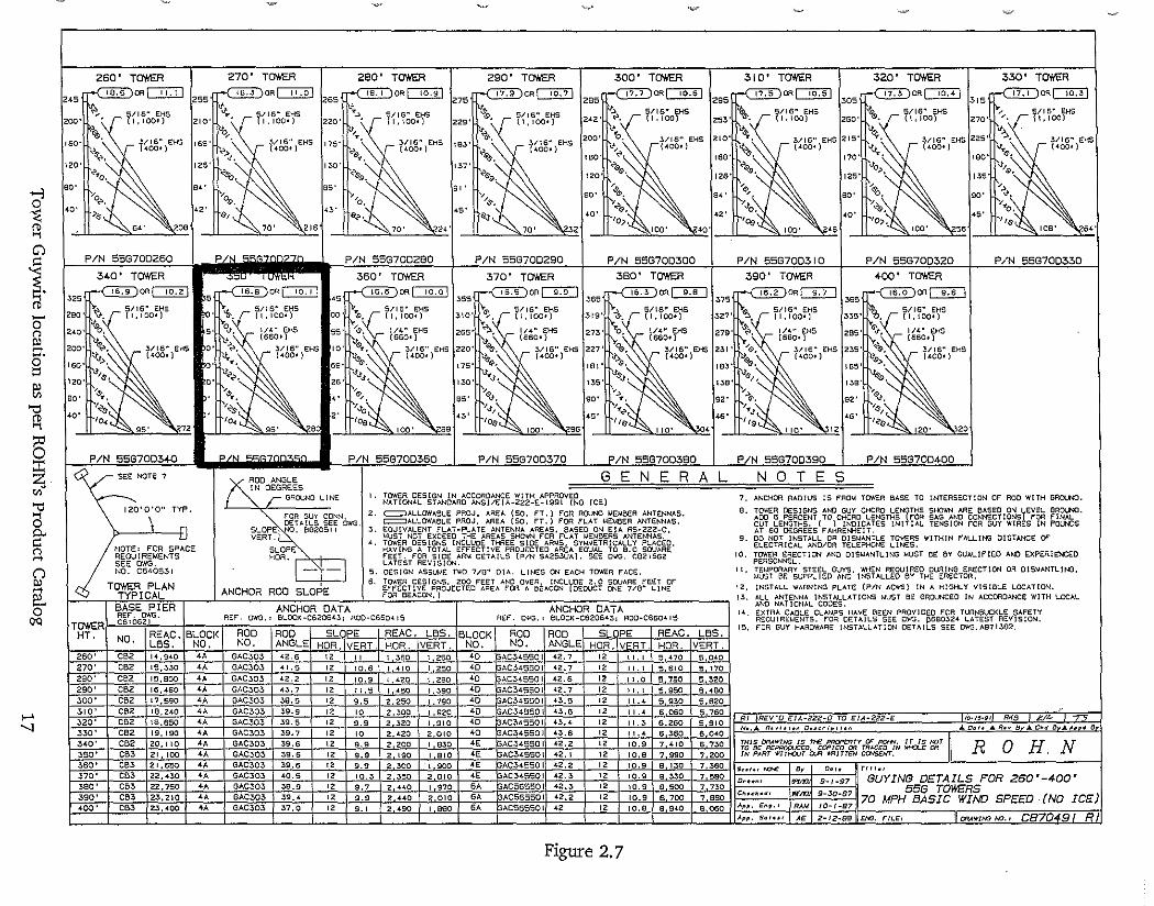
three holes for attachment of three guywires only. As there were four guy wires instead of three, the fourth guywire was fastened to the middle hole's eye bolts (ie. two guywires shared the same hole, see Figure 2.4) at two anchor plate locations. At the third anchor location, an additional hole was provided to one side of the plate for fastening of the fourth guywire. See Figure 2.4. The inner anchor steel rods were embedded into the ground and appeared to remain undisturbed. The outer anchors, also 1200 apart, were located ata distance of approximately 280 ft from the tower base. The steel plates with four guywires attached appeared undamaged. However, a substantial length of the steel anchor rods was exposed. See Figure 2.5. The anchor rods for this type of guywire attachment are generally intended to be embedded a minimum of four feet into the ground, see ROHN's construction details - Figure 2.6. Information contained in the ROHN's Commercial Product catalog referred by the contractor indicates that towers of this height would normally be braced with eight tension guywires in each tower leg, five of the upper guywires to be attached to the outer plate anchored at approximately 180 ft from the tower, and the lower three guywires to be tied to the inner plate and anchored at approximately 100 ft from the tower base. See Figure 2.7. The gin pole was attached to to the tower legs with wire ropelhook. The upper hook had a safety latch that was defective, and the lower snatch block had the safety latch removed.
10

The Buckled Middle Tower (Section 16)-top photo The Rotated/Bent . Tower Base Plate- bottom photo
Figure 2.1
11

The Corroded Lower Tower Members (Sections 22 and 23)
Figure 2.2
12

Snatch Block and Tower Sections 24/25 Rested On Top of The Building
·. Figure 2.3
13

Three inner anchors
Figure 2.4
14

Figure 2.5
Tirree outer anchors-showing exposed steel rods 15

&, ""-"';:-:: -_.
\ ~, -r \ :1 ,
, ~ ..
0 RE/A//ORC/#G . LJ ,...f'E/J.V,cORC/.tVG \,~
;;;;:;;;.:~#-'~"i,CS,&,j11-~/ 'LSI<
LIARS EACh" H/AY' LJOTH /ACES .
d("i~"}I;} /i:15 ;.4~ -: .~' .. I t~:· I y ,:,:", ~.:-:
••.•••• _ 'f. '".
::~:: ,:~<:C.>,<§,~/; z'cJ L~.-J La-J 2,,-J L~---l L-:--J
A#CH'OR OE7A/L ,cOR GAC30· AA/C#OR IJE7A/L ,e'OR GAC 34, 5", 57, (' 58
SIiOIf/II/ 011/ IJj{/G. #0 C 6'6'04£/5 ..eJ1 ./VOTE.' LJ//E TO yA1R/./JL1LES /dJ/OLyELJ /...v..eOOr"A'#.o Or//£R/A/f.T".9'L".c4Qo..-YJ:, /rS//A7LL .6'E/#E CL/S.n:.JA4'E,e.:JO.R/#JT/9t1LE.R:P
.RE.F.A?Hs/&/L/r..r TV .PROY/DE J'TRdCrUR/?LLY fi'LJE.0//4rE s/./,o,oo.ers- r"OR .P/E/f! <F ,9/VC.......ORCON#EC,l70/V..>. /TA?"fi"y AJ.£.J"O 8ErVECESS".9RY .,.cae TAI'"E CL/.,rrOA-fER O.,e //Vsr.Q.!..t.ER TO U'ECORE /7¥ESERWCEClF/?L.OCRL E/VC/A/EER.TO LJETERY/A/E T///97" /#JT/?LLRT/O/V COA?'PL/ES fY/rh/LOC4'L &:y/L.o/N~ cOLJES'
IlFC'~ RFQU/RED ,MATER/At SPECIFICAT/ON;"INSTALLA'TION .11 NOTES AN/) TOLERANCES 3££ DRAWIN6 NUMBER 884/300.
L?L?/ER..9L /VoTES
I. H/#/#t/N ~ "LJ/AH£7ER RE/#,...eORC//!/C dARS /A/ ALL AA/C#ORS J1//,TH #AX/#O# S?AC/A./G Or /2 "EXCE?r #0 /08LOC./; fl'7AX/Nt/,,4? S?AC/A/C or- b~'
CONCRETE AA/Ch'OR LJATA IJE/'711.0
oROIJ A/O. BLOCA' AA/CIIORIJ,wEtVS/OAIS ',e'T.) If/E/GII7 COtVCRE7E {//,L/,c7 .. LA7ERAL
,,cT.J #0 A B C 'a:M::fy//(l,w ,CV YlJs.) CA,PAC/7n2,w C4/'AC///<?/lSJ
.3u /.5 /.5 / .3/0 .08 300 /-500 3b· 2 2 / 560 ./5 /- ..3.?0 2-000--
2-5003 GACJO 3e 2.5 2.5 / 870 . .2.3 /-8/0 3d .3 .3 / I /-20'0 ._ . .3.3 2.5.35 3,000
! 3e 3 4 / ~b80 .44 .3,020 4,000-'j 4u' S. -, 3. ·/,5, /,890 ;50": .3,,490 5,,850 (,;
GAC,JO 4b .3 4 /.5 2-520 .67 4".3bO ;;800
4 I OR 4e .3 .5 /.5 .3,(,50 .84 4,985 9J50 I
l GACJ1i 40' .3 G /.5 ..3,,780 /.00 G,090 //-700 I
4e 4 6 /.5 .5.050 /. .3.3 7, GG'O /~7CO--
6u .3 4 /.5 2,520 .67 /0,0.35 /..?,£OO -
6 GAC5G 66 .3 5 /.5 3~/50 .84 I/, 600 /5,750 6e .3 0' /.5
~ 3.780 /.00 /.3,/50 /8,900
-~ 4 6 /.5 5,050 /. .3.3 /5,850 /8,900 8u .3 5 /.5 "J./SO .84 .?L: 150 2/-750
GAC 57 86 .3 G /.5 .3,780 1.00 24,700 26',/00
8 8e 4 G /.5 ~O50 /. ..3.3 28,500 26;/00'I 80' 6 0' 2.0 /t<800 2.67 _ .3.3,.380 .33.0'00 IOu .3 G 2.0 5,040 /. .3.3 S7.450 4.3,200 /06 4 6 2.0 6;720 /. 78 4~700 ~200
/0 GAC 58 /Oc 4 7 2.0 7,84 0 2.07 46,800 50,400 /00' 5 7 2.0 9,800 2. 59 52,.350 50.400 jOe .5 9 2.0 /2. GOO .3. ..33 6/,700 64,800
* lA/eLl/DES S/lFC:TY r/iCTOfi! OF e
* *..-t-VRff......L SO/L /S A CONC"S/V£" 7YPE so/{. W/TH /I HO/?/ZONTAL. ROHN<!l MANUFAcru_IHG8E17/<,//l/6 CAPACITY OF 400 .A?tlNDS P<R sauARE FooT ..PCR
L//VE/'lL. FOOT OF DEPTH. ,.€t)CK ~ /'l.k;)N - CONeS/V': SO/LS ~ .,.",.,., <§i? OR S/lTVR/iTEO OR SUSI'I'ER6£D SOILS /1RE: NOT m B< n~
CONS/OCREO h'S NOR/'f/U. ~ N cY/S: V WCH'<:1R " ./ .' STA'IVOh'RL? CO;f/CRBLA;f/C//ORS
N'; '</#PP'/LJ A'J'•.?.?.2-.,f/:. ~...,.. C'//P.A/dR l:1./. '-'77 CL. R, ..9.0.0£.0 /VOTe 7~6y6 0# THI,.DR"WIH" '" TH~ .."O..~..H 0" 1t0HH. IT ". Mar TO DE '1"1"" MO.
"~""ODUc.E". C~IEO. 0 .. T....C~O 'N w""U; 0" 'M ......T £0 RE'V/SC O£S/tS/o/ .NUT.!" /. /-/"? "'"" WITHO""- OUA WAlne.. c.ot<SCt<T.
R, ,R'£Y/JE OC:S/Gt'/ A'1::'TE /. ~ T/TL£ aLOe /h?/·· Wi'« "'''IVONE ..... .....~ "
R. GAC-Z5 WAS GA'ZS 1t.-7-7. JER •••.•• GLS .." • 7.' :::-~".....: o,~••""............0. OI"'O...~ •••_ ......,._
R.:oJ ~#C,f'E.AJ'£LJ ,f'OL) LEN(;THS/ fJO"-'itil -"3 ,f'E'P/SEC /0£ EM .t'S~.?.?.?·LJ W7.:! GLS < .••
··:?-4-73 y;." 1~/~1 /HRT A-V. (;ACJO IVAS 6iACZS ~ D"'lO"''''''T'OM O'n .. ·-j>.w·· ·'11-<1·73 ... "~~"";...., 6'206"437. lot/KU v,"""Ab"'~ t' ACf)£f) 3'<Sl:fI_X1<:GYOT.tl '·".f/iRK!; __ "",V''''O''IO '--lJ'!?' ~;1~c.-7J
Concrete Anchor DetaiIs-from ROHN'sCatalog Figure 2.6
"o·V
'd ~ ~ Cl
1(b
0" '"0' O. § ~
"0 ~
6::c z ","
8' g-M '" n [ 0'
~
>-' '1
2~T~R 270' T~R 280' T~R 290' T~R 300' T~ 310' T~R 320' T~R 330' T~
~ORCJJ:IJ ~OR~ IS. I OR~ 17.9 ORD:2:1J 17.7 OR~ " 5 ORc:I:2:D 17.3 OR~ 17. I ORc:::I§ 245 fv. 255 265 275
~ 2B5 295 '05 "5
~.... r/15~ EHS 0 S/15~ EHS '>. S/15~ EHS S/15~ EHS "> S/15~ EHS ":.. 5/15" EHS ~. 5/15" EHS ". 5/15" EHS
200" 1,100') 210' '. (1,100' ) 220' (1,100' ) 229' ~.
(I, 100-) 242' e. (1,100) 25::!>' (1,IDO) 260' (1,IDO) 270' 1l.100)
150' ~~ ~/16" EHS
~o ", i'>",. 200'
\~ 210'
;~'215'
;~-225'
~ '. !o/16" EHS '. ~/15" EHS t/16" EHS16S' 175' 183'
"':~ "00" ~ (400')
"O~~ '''0'' "':~ '00" ~ (400_) e> (400_) e. (~OO. )
e~ 400_ )
~" <. '. •• 150' 16S'
.;;~ 170' 180'
120' 126' I::!>O' 1~7' ""•. <0>,,, 0, ~"o, %0. ~S.9. ~6'.s>. ''0 125' 125' 135'
~,
BO' B<' 85' g,'
':~ '. ~~ '::~
'0 'q,. " " BO' B<'
~;0'0l BO' BO' e, 0, e, '. [Y"o.'" ". ". '5' '0'
.. 0, '0' <S''s, e" ,,<>. "J, '0, '" I~'~IOO' '8
'0, r-',(S,". 20B 70' 216 70' Z<' 70' 32 '~IOO' .40' • ~IOO' 55 ~108' 54'
PIN 55G700260 P ,m"," PIN 55G700280 PIN 55G700290 PIN 55G700300 PIN 55G7003 I 0 PIN 558700320 P,IN 55G70D330 340' T~R 360' T~R 370' T~R 380' T~R 390' T~R +00' T~R
16.9 OR~ 16.8 OR~ 16,5 OR~ '1"5."5' OR ~ ~OR~ ..JIL' OR CIIJ "'i6':"O"'OR~
'" "'e .5
"'",. <S
"', >5S 065 375 ::!>8S ""----' 5/16" EHS 5/16" EHS 5/16" EHS
" 5/16" EHS ->. 5/16ft EHS ~ 5/16" EH5 ~: 5/16~ EHS2BO' O. ( 1,1000) 0' (1.100' ) 00' ~. (1,100' ) ::!>IO' (I, 100') 319' (1.1000) ~27' ~, (1,100') 335' , (1,100_)
240' "'b, 5' °0. 1/4" EHS 55' "'oS', 1/4ft EHS 285' ~'" 1/4 ft EHS 27:5' "0 1/4" EHS 279' 't. 1/'" EHS 285' G'...,.. 1/4ft EHS (660') tI: (660') I) , (560') 1\0
0 ' (660') 1\".... (G60') (G60_)
"~. "> ~~. 3/16ft
EHS200' ::!>/16" EHS 0' e, 3/16" EHS '0' i9", V 3/16" EHS 220' ~:~ 3/16" EHS 227' ~, 3/15ft EHS 231 ' ]'v~~' 3/16~ EHS 2~S'
't>, (400.) "-. , {4OQ' ) 'h~,:~ [400' ) ~ (400-) t/"> (400') ~:~ (400_) ~>, (400')
150' 0' 6B' 175'
:~ 181' ~, 183' IBS'
'J1$, """c...::
'~" 'J"J', 'J$J''-:: ";;~ ".120' 0' 26' ''''' 13S' 1:58' ~"'~.~ 13S' ."'. '~~~ '. ,.~~ '>~~ '.BO' " ,.
;:{ '00' B8
B5' 90' 92'
~{ 92'
'i~'''e ! '''e '< '. ~"J', '0' 2' '" ,:e ~ 100' lto.296
<S' e,
<S' <S' '0. 10~ ~ ". ". '<.
96' n 96' a ~ 110' 04 110' ~12 ~ 120' 20
PIN 5587003+0 " '" PIN 558700360 PIN 55G700370 PIN 558700380 PIN 55G700390 PIN 55G700400
ySEE NOTE 7 '«J!0 ANGLE G E N E R A L N 0 T E S IN DEGREES r GROUNO l.INE I. TQ',\£R DESIGN IN ACCORDANCE WITH APPROVED 7. ANCHOR RADIUS IS FAO~ TOWER BASE TO INTERSECTION Of" ROO WITH GROU'IO.
\ 120'\0" TV:"
NATIONAL STANDARO ANSl/EIA·222~E·1991 (NO ICE)
2. o:=::=;lALLOWABLE PRDJ. AREA (so. FT.) rOR ROUNO ~EMBER ANTENNAS. 8. Tcrt.'ER DESIGNS AND GUY CHORO LENfTHS SHOWN ARE BASEO ON l.EVEL GRO\.NO.
,~u, '0" ...00 G PERCENT TO CHORD LENGTHS FOR SAG AND CONNECTIONSt F"OFl fINAL
OETAILS SEE OWG. c=:::J ....LLOWABLE PROJ. AREA [SO, FT.) F'OR Fl.AT MEMBER ANTENNAS, CUT LENGTHS. ( ) INDICATES INITIAL TENSION FOR GUY WIR 5 IN Pot.JM)SSLOP • 682051 I 3. EQUIVALENT FLAT~PLATE ANTENNA AREAS. BASEO ON EtA AS~222-C. AT 60 OE.GREES FAHRENHEIT <
I/NOTE' FOR se~CE VERT. MUST NOT EXCEED THE AREAS SHOWN FOR FLAT MEMBERS ANTENNAS. 9. DO NOT INSTAl.1. OR DISMANTLE: TOWERS WITHIN FALUNG OISTANCE OF
.... TOWER OESIGNS INCLUDE THREE SIDE ARMS, SYMMETRICALLY PLACED, ELECTRIC"L AND/OR TELEPHONE LINES.SLOPE HAVING A TOTAL EFFECTIVE PROJECTEO AREA EOUAL TO 8.0 SOUARE
10. TO'IIER ERECTION AND OISMANTl.ING MUST BE BY OUAl.lfIED AM) EXPERIENCED REOUIREMENTS HOR. !'EET. !'OR SlOE ARM OETAIl.S (P/N SA2S3UA). SEE DWG. (';821652 SEE OWG. [-1 l.ATEST REVISION. PERSONNEL. NO. C64053I 5. OESiGN ASSUME TWO 7/(I~ 01.0.. LINES ON EACH TOWER !'ACE. II. TEI.!P~ARY STEEL GUYS. WHEN REOUIREO DURING ERECTION OR DISMANTLING.
MUST BE SUPPLIED AND INSTALLEO BY THE ERECTOR.
TOWER PLAN ANCHOR ROO SLOPE 6. TOWER OESIGNS. 200 FEET AND OVER. INCLUDE 2.0 SQUARE FEET OF
12. INSTAl.l. WARNING Pl.ATE (P/N ACWS) IN A HIGHL'l' VISIBl.E LOCATION.EFfECTIvE PROJECTED AREA fOR A BEACON (OEOUCT ONE 7/8~ l.INE TYPICAL FOR BEACON.) !3. ALL ANTENNA INSTALLATIONS MUST SE GRQUNOEO IN ACCOROANCE WITH l.OCAL
BASE PIER ANCHOR DATA ANCHOR DATA ANO NATIONAL CODES. 14. EXTRA CABLE CLAIAPS HAVE BEEN PROVIDED FOR TURNBUCKLE SAFETYREf. DIIIG. REF. OWG., Bl.OCK~C620643; ROO-C660'15 REF. 0'/.'8., BLOCK-C62054::!>: ROD~C650415 REOU1RE::J.lENTS. !'OR QETAILS SEE Q1,'O.P.6B0324 LATEST REVISlON.
T~R C610621
15. !'OR GUY HARDWARE INSTAl.l.ATION OETAILS SEE DWG. A87 1382. HT. NO, REAC, BLOCK ROO ROO SLOPE REAC. LBS. BLOCK ROO ROO S OPE REAC. LBS.
LeS. NO. NO, ANGLE HOR. VERT. HOR. VERT. NO, NO. ANGLE HOR, VERT. HOR. VERT. 260' CB2 14,940 " GAC303 42.5 " " I 350 1 2S0 40 AC345501 42.7 " 11.1 S.470 S 040 270' CB2 IS,330 " GAC303 41.5 " 10.6 I 410 I 250 .0 AC345501 42.1 " 11.1 S 610 5 170 280' CB2 15,SOO " GAC303 42.2 " 10.9 1,420 1.2BO 40 AC345501 42.5 " Il,O 5 790 5 320 290' CB2 16,460 'A GAC303 43.7 " II.S I 450 1.390 '0 AC345501 42.7 " 11.1 5.9S0 5,480 300' CB2 11.S90 'A GAC303 ~8.S " 9.5 2.250 1.190 '0 AC345501 43.5 " 11.4 S 930 5.620 310' CB2 18,240 'A GAC303 ::!>9.9 " '0 2,300 1,920 4O AC345S01 43.6 " I I ., 6.060 5 160 ~
R' REY'O EIA~222·0 TO EIA~222~£ 10· "·S' RKB gR_ ~ 320' CO2 18.650 'A GAC30::!> 39.S " 9.9 2 320 1.910 .0 AC345501 4~.4 " 11.3 6 250 S 910
N..... R"''''M D'Hd ".~ "'D.' .... R_ .. B ",Ckd B AAp d 8 330' CB2 19,190 " GAC303 39.7 " '0 2.420 2 010 .0 AC345501 43.6 " 11.4 "50 6 040 340' CB2 20.110 4A GAC303 39.6 " 9,9 2 200 I 830 4E AC34550 I 42.2 " 10.9 7 4.10 6 730 THIS DRAWING 15 THE: PRDP~RTY OF RDfN. IT IS NOT 11 R a H. NTD BE R£PRDCJIJC~D, COP1~D OR TFI),C~D IN II+Q..~ O'l 350' CB' 21,100 4A GAC303 ::!>9.6 " 9.9 2 190 I 810 '" AC345S01 42. I " 10.8 1 990 1,200 IN PART WIfH()IJT ~ mITTEN CONSENT.
360' CB' 21,650 'A GAC303 39.5 " 9.9 2 300 I 900 '" AC345501 42.2 " 10.9 8 130 7 3BO Sui .. NJN!: " D~,_ Til 1., 370' CB' 22,430 4A GAC303 40.5 " 10.3 2 350 2 010 4E AC345501 42.3 " 10.9 8 330 7 580
D'-U'n, ",,'" 9~ 1-97 GUYING DETAILS FOR 260'-400' 380' CB> 22,7S0 4A GAC303 38.9 " 9,' 2 440 I 970 6A AC56550 I 42.3 " 10.9 a 500 7 730 55G TOW£RS 390' CB' 23,210 " GAC303 39.4 " 9.9 2 440 2,010 6A AC565501 42.2 " 10.9 e,7oo 7,880
Ch.ck_d, """ 9-30~87 70 MPH BASIC WIND SPEED (NO ICE) 400' CB> 23,400 4A GAC303 :57.0 " 9. , 2 490 , 860 6A AC565501 " " 10.8 8 940 8 050 App, fi~,., R4" IO~I-87
),pp. S~I .. , 4£ Z·IZ~OO ~NG. Fll.fi' II DRA'IIIN3 m., CB7049{~{
Figure 2.7

3.0 SlRUCfURAL ANALYSIS AND DISCUSSION
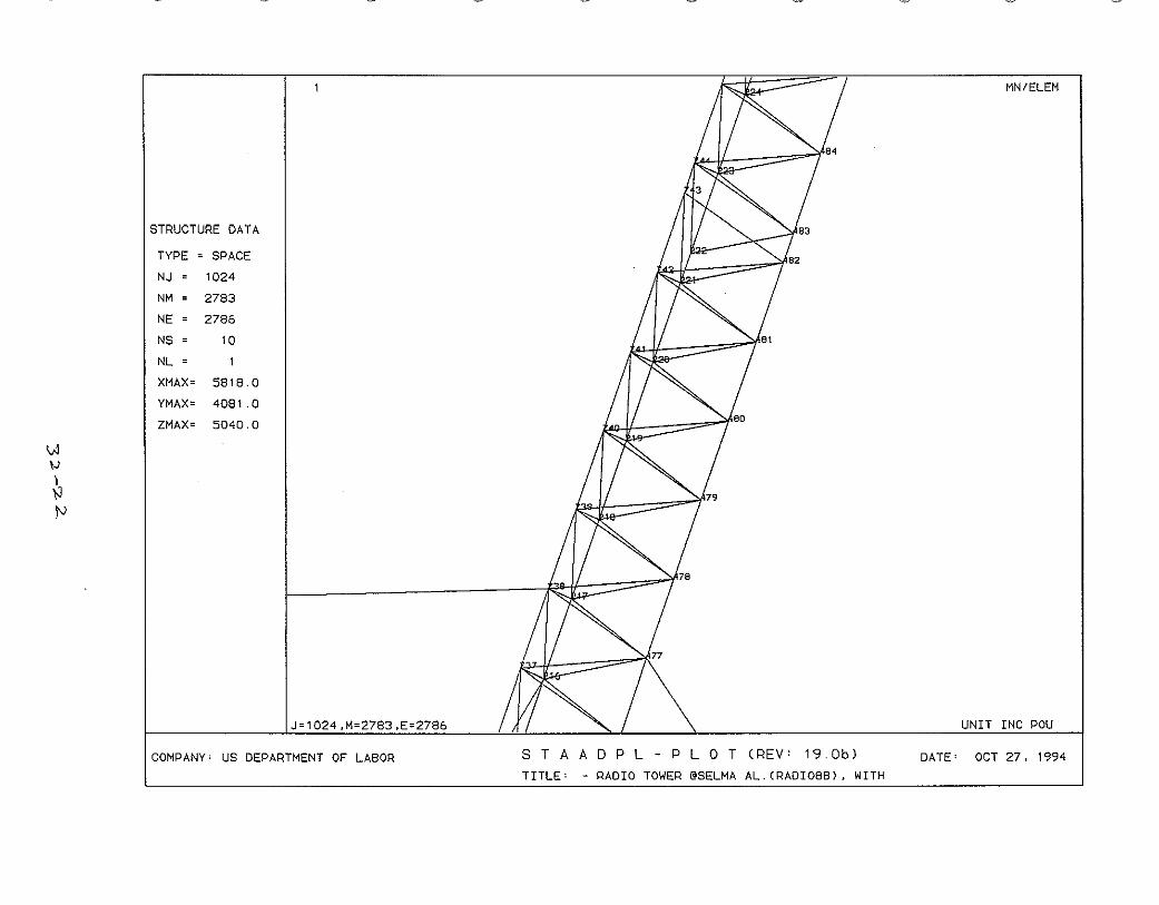
Structural analyses were performed to determine the internal member stresses of the tower for the various loads experienced by the structure since the completion of the tower and the application of tensioning forces in the guywire cables. Based on the field measured dimensions, erection details provided by the contractor, and ROHN's catalog obtained from the manufacturer, a three dimensional model of the tower structure was developed and used for the structural analyses. See Figures 3.1 thru 3.7. This computer model consisting of 1024 joints and 2783 member elements represented the structure consisting of the combination of three different constructions; the bottom 80 ft of steel pipe construction, the middle 120 ft of solid pipe sections, and the upper 150 ft of new sections manufactured by ROHN..
Three guywires were modelled at each of the eight levels, the guywire cables were defined as tension members in the model and were subjected to tension forces only. The horizonal and diagonal members were assumed to be rigidly connected as they were welded to the main vertical legs of the tower.
The lower tower sections had extensive corrosive damage as discussed earlier. Wall thickness of the steel pipe member, as result of the corrosive damage, was decreased from its original 3/16" to 1/16" - 0.01". The most severe corrosion occurred between tower sections #22 and #23 at elevation approximately 50 ft to 80 ft above the base. Several analyses were performed with varying wall thicknesses in this area. Longitudinal split at some locations was also observed at the lower tower sections, but was not included in the structural evaluation. Laboratory testing to determine the material properties of the tower sections were not conducted and the analysis was based on the yield strength of the steel to be 50,000 psi. The weights of three antennas and two construction workers near the top of the tower were deemed insignificant and therefore were not considered in the analysis. The structure was then analyzed for the following conditions.
Case 1: The tower structure was analyzed based upon its original member sectional properties. Loads imposed to the structure included the tower's dead weights and the guywire tensioning forces. The guywires were assumed to have been tensioned to approximately 10% of their ultimate strength based upon the contractor's statement. Lateral forces such as wind load and other side load were not considered. Under this loading condition, the maximum combined stress (axial stress plus stress due to flexure about both principal axes) of the column members at the lower section of the tower was determined to be approximately 10,300 psi. The maximum stress at the middle solid pipe section and upper ROHN section were 11,400 psi and 8,600 psi respectively.
18

Case 2:
Case 3:
Case 4:
These stresses were considered to be within the allowable values providing an adequate factor of safety based on the yield strength of 50,000 psi of the tower members.
The corrosive damage of the lower sections of the tower was included in this Case. The extent and locations of the corrosive damage to the lower sections were based upon the field observation of the collapsed structure which indicated that the most severe corrosion occurred at Sections #22 and #23 (between elevations 50' to 80' above the base). The steel pipe wall thickness was measured to have been reduced to 1/16" to 0.001" from the original 3/16". To account for the effects of the various degrees of corrosive damage, several analyses were perfonned using different wall thicknesses of vertical leg members between the elevation of 50' to 80' above the base. Loads on the structure included tower dead weight and guywire pre-tension without any lateral load. A wall thickness of 0.06" ( 1/16") resulted in the combined stresses of several vertical members of the lower section to be either close to or in excess of the AISC (American Institute of Steel Construction) permissible values. The interaction value of the axial compression and bending stresses was determined to be either approaching or exceeding 1.0 based on the AISC equation H1-1.
The wall thickness of the leg members at the these elevations was further reduced to 0.03" 0/32") in this Case. The analysis determined that several members of the lower tower structure had a compressive stress greater than the permissible buckling stress, and a combined stress close to its yield strength. When checked against the AISC Equation H1-1 requirements, the interaction of axial compression and flexural bending exceeded 1.0, (for example at member 35, the interaction value was 2.08 instead of 1.0). It is, therefore, believed that some local buckling could occur if the thickness of the lower tower column was assumed to reduce to 1/32". In which case, the structure would have marginal factor of safety against failure: It was further determined that a wall thickness of 0.01" resulted in a maximum member stresses well beyond the metal yield strength. A comparison of the lower section column member stresses is presented for various wall thicknesses at selected locations in Table 1.
The lateral forces imposed on the tower at the snatch block used to hoist the coaxial cables were considered in this Case to examine their effects on the tower structure. A lateral force of 200 lbs applied at 22 ft above the tower base resulted in additional stresses to the various part of the tower. These additional stresses were, however, considered to be small, and the lateral displacement of the tower along its' height was also determined to be insignificant.
19

Case 5: An applied lateral force of 1000 lbs at the location of the snatch block was considered in this Case. The stresses of some tower members increased by approximately 20 percent. The lateral displacement of the tower also increased. This higher lateral load of 1000 lbs was considered to simulate the increased horizontal load at the snatch block due to the reported sudden quick downward movement of the gin pole. The effect of the increased lateral load at the snatch block was considered significant. A tower structure of this type, in general, is not designed for any concentrated lateral load applied at locations other than the guywires or the tower base. See Table 2 for the comparison of member stresses due to lateral loads of 200 lbs and 1,000 lbs applied at approximately 22 ft above the base.
The construction details observed in the project site after the accident indicated that the tower construction was of poor quality. The following as-built conditions had significant adverse impact on the behavior of the tower structure:
1. Re-using of severely corroded tower sections without proper evaluation.
2. Attaching four guywire cables to an anchor plate that was proportioned and intended for three guywires only.
3. Exposing outer anchor steel rods at all three anchor locations resulting in inadequate embedment.
4. Connecting guywire cables to the tower structure without the appropriate connection brackets.
5. Positioning the snatch block at locations other than the guywires or the tower base.
For conclusions, see Page 30.
20

,
uywire Cables (24 total)
~
-----------To Outer anchor
~
Inner Anchor
;rower I
Upper sections
Middle Sections
Lower Sections
Computer Model of The Tower Structure
Figure 3.1 71

0.-- a.-.., _ _____..----"*:._
Figure 3.2
22

,..'-'" ... ~:'
..• ~ ~·-!C POL
Figure 3.3
23
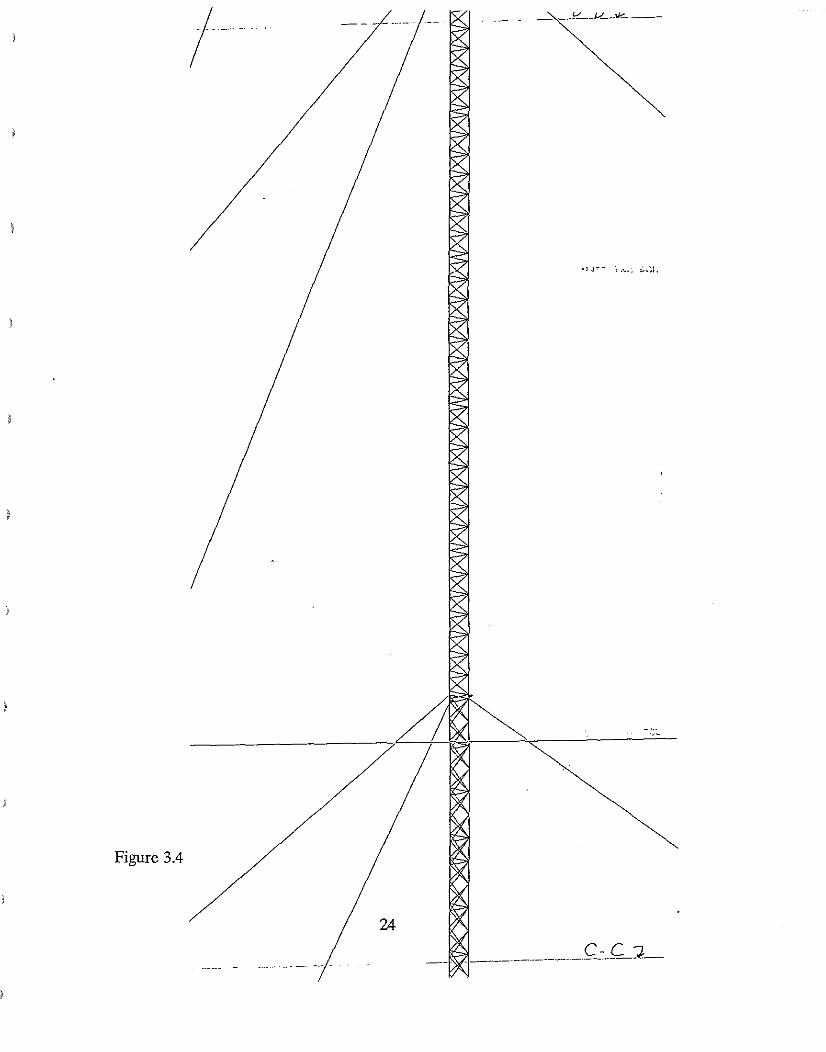
Figure 3.4

Figure 3.5

26
1>(-4--------d -d] IINTT TNC DOL
. •• ~...:.- •".f'.' '
Figure 3.6

)
/
Figure 3.7
27

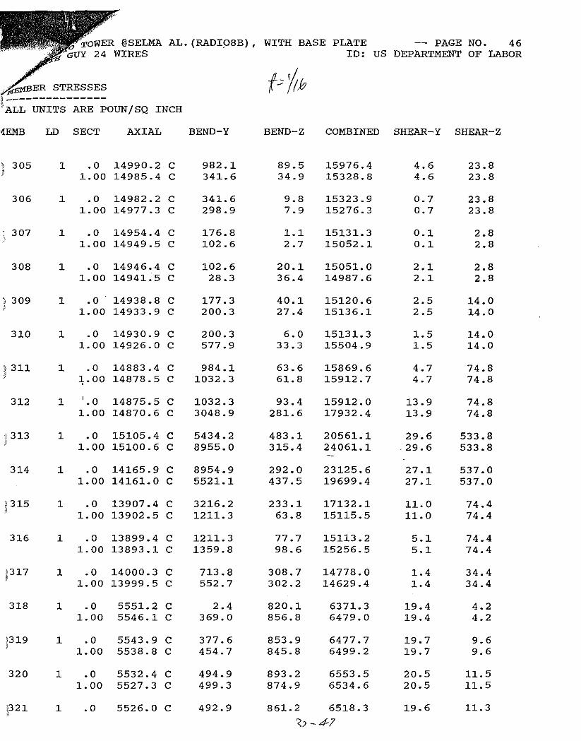
Comparison of Member Stress (PSI) [For Various Column Wall Thickness]
Leg Member # Thickness
t= 3/16" original
t= 1/16" t= 1/32"
01 6,420 6,347 6,327
A 35 10,312 25,665 * 48,671 *
53 9,457 24,061 45,858 *
261 6,420 6,348 6,329
B 295 10,312 25,666 * 48,673 *
313 9,457 24,061 45,858 *
523 7,591 7,503 7,477
C 557 7,480 20,458 40,052 *
572 7,311 20,054 39,409 *
*Exceeded AISC Design Requirements
TABLE 1
28

Comparison of Member Stresses (PSI)
Member # Horizontal Force (H)
H= Olbs t = 1/16"
H= 2001bs t = 1/16"
H = 10001bs t = 1/16"
H= 10001bs t = 1/32"
1 6,347 8,333 10,090 10,061
15 6,298 6,457 4,469 4,503
35 25,665 25,669 27,651 52,552
261 6,348 3,442 2,430 2,429
275 6,299 6,556 14,264 14,257
295 25,666 25,664 31,389 59,024
523 7,503 9,154 11,235 11,201
537 7,362 7,368 5,208 5,180
557 20,458 20,445 20,725 40,555
TABLE 2
29

4.0 CONCLUSIONS
Based on the above evaluation and discussion, the following conclusions are drawn:
1. Not withstanding the corrosive damage to the lower sections of the tower, the 350' high tower as erected was detennined to be capable of supporting the intended loads.
2. Not withstanding the corrosive damage to the lower sections of the tower, the application of a side load of approximately 200 lbs at a height of about 22 ft above the base would not result in stresses of the tower members in excess of the allowable values.
3. Following the construction of the masonry building for the electrical equipments, the snatch block was repositioned from the base to a location which was approximately 22 ft above the base for hoisting of antennas and coaxial cable. The tower structure of this type in general is not designed for an application of a substantial concentrated lateral load at locations other than at the guywires or the tower base.
4. The corrosive damage to the lower sections of the tower was extensive. Due to the extent of the corrosive damage, the vertical legs of the tower were subjected to stresses beyond their allowable values.
5. The extensively corroded tower sections salvaged from other older towers were reused by the contractor without any proper evaluation. The structural integrity of the tower structure was rendered questionable as a result of using the corroded used tower sections.
30

Appendix-A
Contract Agreement
31

-- -
-+=~1ff-;,;8:w.7,:!5:.::-:.;9'"'3~6"-IL--...l..-=......u-=-----.- ;:j'f""r~.......s"'c Q tt III en Q [) d e • ~TI'df
Hazen,.. At.
~IN. .,.ATt U40 " ¢OOC
- (MTC 0' I'UJiS' 1'>,,1111" "1.
30 to ~5 aa s Fax 205w87 -
Installation of a 350' FM Radio Touer (3 Bay Ant.)
Includes ~oundationfhanging fM antenn and STL dish, and painting tower.
) The t.oile~ \.~ill cons1st of ..150 1 of 18" x 20' solidleg X-bracAd f;~ctions
and 200' of Rohn 55G Towar,guyvirc and anchors.
One Used Lighting Kit Includes; Two used bQacons, and six sidelights,
-scott Alexander will furnish all ants., coaxals,and mounting hardware.
TOTAL COST: $15000.00
, ~ wir 'Hill 1M ruu WTT><IH JtI ~Y$ '" 't<¥OlQr '04Tt lI'1u, A\Il'O....n<;A~~Y nC»..l W"'llJT 11) • nH"'ac et<A.QL floI( tlKAJtCt Cf141'10t is AT 'n,! MDKTxl. r ft(fII'l¢OIC jl;J,1( Of 1\0\% pi"" ,!It AJoj~IJM.1
-",=;;-o:===i:/,.f.,(rr.:::"..,..-----------'F'-'~=-' (J"f"-"t",e,-,e",n"--,t",h,,,o,,"u=s,,,a~n,;,:, <ioll". ($ 1 50 0 0 ' 00 .....yol\f/l, I. GO ;W; •• l.iI".."
$950Q.OO for tow~r & Lights! $300C.OO to Start /$2500.00 completi .. ... ..
".11 _~ \r& .",,*(lIoA~ If' ..... ,~~. A.4 ~ tf !Jot ~~.., i.\ • ~"".n"'W
-.".- ............"'r ~ .t.I.o4t... fI"~"'''' Mt .n,..'\..... ftt ~t""'" CtoM .~ """,l~' ~'"",,I int'OtrillC ..~tI, (".1• ..-iU "'" .1~"'lto Qflly"~ ..,lntn ......<u•••~ .. I" H<(k'fl4 41i
.·:r. ,"'tH:ttr""".h9.~Ih. ul/"",I•. All.tr ....m ..nh ~ntin"m.lliJ1l'n Jlf'''U, 'l;~k1tnt•
.. .wt.l~ ~ INI fioI,tI.l. 0..- , f., cttl) "ti, t9'""'~ 11004 ~""f II"flWry lnl'u~,. ?",' ~Il '('f (Itll)' 'yvtlJK!. irJ We "·. C~lInliJ'l""'I"'t1 jn'l,If'PlC1,
Nutd:!utn! ttf Jnt;1l:ll!a1-Tho ...".. "" ..., ,pooll,...lon• .;~ u.~ ~O"~-I-;;'- $-IdSf~Ol)' ,rn1 .rr r..f,t1y ,ce"p-itd. You art ,f.ltlMI(iztod
IQ Q9 ~~ n ~~tn.,. Ptymtf\t wHl bf; rnf4t. ..~ QUlHntd alX1tt.
-.'. .iA~ --__A _
** THE ACCEPTANCE OF THIS PROPOSAL IS SUBJECT TO FCC APPROVAL OF THE 'l'RANSFER OF THE WJAM-FM CONSTRUCTION PERMIT FROM MARION RADIO TO SCOTT COMMUNICATIONS INC.
10d c::.t-Lt' 63~ S0c : 'ON 3NOHd ~3r'11]1 883f'1 : I,JDd3
Appendix-A
SI(l\.Jlu
OilT"'

Computations
32

,TA
:E
~( 3 0 ~ 1.0 ~ )0
G.
~ \l. C\ ~
'IJ', ~ ' ~
~. ~
~
~
J=1024.M=2783.E=2786
'~,w' ""'/ \'J" ~
.... ~
-\~
e, I Ii)~
: I 194
-
UNIT INC POU
DEPARTMENT OF LABOR S T A A 0 P L - P LOT (REV: 19.0b) DATE: AUG 15, 1994 TITLE: - RADIO TOWER @SELMA AL.(FILE NAME-RADIO

:::J o 0
U Z H
IH
Z :::J
\J)
~
'1 -'-.:l. c
~ (J) ~
':::?-~
oJ
'--'Q --I..l 0 ~
l
e
-..n <> 0
0
c: <;
--9 <;~ -'" I
(j
-n ill 1'N II
W ((") (ill (1'
N II
::E l (..,
N aj-
II -,
(
l<i 0 0 0 (I- W <i U ill 0 0 <i ..,- (") -n 0 ill ..,- ~
0- N m m m 0 0 w en 0 1'- If) ..,- If) 3$-2"

""';J' ..-=/
MN/ELEM
STRUCTURE DATA
TYPE • SPACE
NJ • 1024 NM • 2783
NE = 2786
NS • 10
NL • 1
XMAX= 5818.0
YMAX· 4081.0
ZMAX= 5040.0
I ~,
N 1
<i:.
JOllJfrJ~. UNIT INC POU
COMPANY' US DEPARTMENT OF LA80R S T A A D P L - P LOT (REV' 19.Gb) DATE' OCT 26, 1994 TITLE' - RADIO TOWER @SELMA AL.(RAOI088l, WITH

- -
I:'-' ""I i"
,"",,;, ~
([;) 7 MN/ELEM
STRUCTURE DATA
TYPE = SPACE
NJ lD24
NM 2783
NE 2786
NS 10
NL 1
XMAX= 5818 0
YMAX= 4081.0
ZMAX= 5040.0
UNIT INC POUJ=1024,M=2783,E=2786
COMPANY' US DEPARTMENT OF LA80R S T A A 0 P L - P LOT (REV· 19.Gb) DATE' OCT 26, 1994 TITLE. - RADIO TOWER @SELMA AL.(RADIOSS), WITH

-
\-.J ~
)
\JI
""if
MN/ELEM
STRUCTURE DATA
TYPE = SPACE
NJ 1D24
NM 2783
NE 2786
NS 10
NL
XMAX= 5818.0
YMAX= 4081.0
ZMAX= 5040 0
J=1024,M=2783,E=2786 UNIT INC POU
DATE· OCT 26, 1994
",,"" ~ ~
COMPANY· US DEPARTMENT OF LA80R S T A A D P L - P LOT (REV' 19.Gb) TITLE' - RADIO TOWER @SELMA AL.(RADI088), WITH

."w/
\A,
'N, ~
MN/ELEM
STRUCTURE DATA
TYPE = SPACE
NJ 1024
NM 2783
NE 2786
NS 10
NL 1
XMAX= 5818 0
YMAX= 4081.0
ZMAX= 5040.0
UNIT INC POUJ=1024.M=2783.E=2786
COMPANY· US DEPARTMENT OF LABOR S T A A D P L - P LOT (REV· 19.Gb) DATE· OCT 26. 1994 TITLE· - RADIO TOWER @SELMA AL.(RADI08B). WITH

- - - ",,"'"0/ "-'"
~ ~ \
~
MN/ELEM
STRUCTURE DATA
TYPE = SPACE
NJ 1024
NM 2783
NE 2786
NS 10
NL 1
XMAX= 5818.0
YMAX= 4081.0
ZMAX= 5040.0
UNIT INC POUJ=1024.M=2783.E=2786
COMPANY' US DEPARTMENT OF LA80R S T A A 0 P L - P LOT (REV' 19.0bl DATE ' OCT 26. 1994 TITLE' - RADIO TOWER @SELMA AL.(RADI08Bl. WITH

- ---
o.v
MN/ELEM
STRUCTURE DATA
TYPE • SPACE
NJ· 1024
NM· 2783
NE' 2786
NS' 10
NL
XMAX= 5818.0
YMAX, 4081.0
ZMAX' 5040.0
J =10241.M=2783 ,E UNIT INC POU
DATE' OCT 26, 1994
~
COMPANY' US DEPARTMENT OF LA80R S T A A D P L - P LOT (REV' 19.Gb) TITLE' - RADIO TOWER @SELMA AL. (RADI08S), WITH

'<# ''"-'"''-'' ",y <.,''MN/ELEM
STRUCTURE DATA
TYPE = SPACE
NJ = lD24
NM = 2783
NE = 2786
NS = lD
NL
XMAX= 5818.D
YMAX= 4081.0
ZMAX= 5040.0
I \}J ~ )
~
UNIT INC POUJ=1024,M=2783,E=2786
COMPANY· US DEPARTMENT OF LA80R S T A A 0 P L - P LOT (REV· 19.0bl DATE· OCT 26, 1994 TITLE. - RADIO TOWER @SELMA AL.(RADI088), WITH

~ \
....... "'"
MN/ELEM
STRUCTURE DATA
TYPE = SPACE
NJ = 1024
NM = 2783
NE = 2786
NS = 10
NL
XMAX= 5818 0
YMAX= 4081.0
ZMAX= 5040 0
I
UNIT INC POUJ=1024,M=2783,E=2786
COMPANY' US DEPARTMENT OF LA80R S T A A 0 P L - P LOT (REV' 19.Gb) DATE ' OCT 26. 1994 TITLE' - RADIO TOWER @SELMA AL.(RADI08Bl. WITH

-----
'*''''
\l'! Iv Z
MN/ELEM
STRUCTURE DATA
TYPE = SPACE
NJ = 1024
NM = 2783
NE = 2786
NS = 10
NL
XMAX= 5818.0
YMAX= 4081.0
ZMAX= 5040.0
J=1024,M=2783,E=2786 UNIT INC POU
COMPANY· US DEPARTMENT OF LABOR S T A A 0 P L - P LOT (REV· 19.0bl DATE· OCT 26, 1994 TITLE. - RADIO TOWER @SELMA AL.(RADIOB8l, WITH

----
'ije""
MN/ELEM~6'
STRUCTURE DATA
TYPE = SPACE
NJ ~ 1024
NM = 2783
NE ~ 2786
NS = 10
NL
XMAX~ 5818.0
YMAX~ 4081.0
ZMAX~ 5040 0
~ 1
';J
J~1024,M~2783,E~2786 UNIT INC\POU
DATE' OCT 26, 1994COMPANY' US DEPARTMENT OF LA80R S T A A D P L - P LOT (REV' 19.0b) TITLE' - RADIO TOWER @SELMA AL.(RADI08B), WITH

VJ \--' \
\J:;
.",,,,. ~"'''''
MN/ELEM
~r
STRUCTURE DATA
TYPE • SPACE
NJ = 1024
NM· 2783
NE = 2786
NS • 10
NL • 1
XMAX· 5818 0
YMAX· 408 1. a ZMAX· 5040.0
J=1024.M=2783.E=2786 UNIT INC POU
DATE· OCT 26, 1994COMPANY· US DEPARTMENT OF LABOR S T A A 0 P L - P LOT (REV· 19.0bl TITLE· - RADIO TOWER @SELMA AL.(RADIOBB). WITH

~ ~ ""'"
\>J '" ~ ~.
.._J"'-""
MN/ELEM
STRUCTURE DATA
TYPE = SPACE
NJ 1D24
NM 2783
NE 2786
NS 10
NL 1
XMAX= 581B.0
YMAX= 4DB1.0
ZMAX= 5040.0
UNIT INC POU1~3'E=27B6 COMPANY' US DEPARTMENT OF LABOR S T A A 0 P L - P LOT (REV' 19.0bl DATE' OCT 26, 1994
TITLE' - RADIO TOWER @SELMA AL.(RADI088l, WITH

~ '0/
MN/ELEM
~r
STRUCTURE DATA
TYPE = SPACE
NJ 1024
NM 2783
NE 2786
NS 10
NL 1
XMAX= 5818.0
YMAX= 4081.0
ZMAX= 5040.0
"J,), ~ "\
~
J=1024.M=2783.E=2786 UNIT INC POU
DATE' OCT 26. 1994COMPANY' US DEPARTMENT OF LABOR S T A A 0 P L - P LOT (REV' 19.0bJ TITLE' RADIO TOWER @SELMA AL.(RADIOBB1. WITH

-----
\)j,
I'.> \
'S'-.
,-.,' 0P;- ,.....,'
MN/ELEM
STRUCTURE DATA
TYPE = SPACE
NJ = 1024
NM = 2783
NE = 2786
NS = 10
NL = 1
XMAX= 5818.0
YMAX= 4081.0
ZMAX= 5040.0 I
UNIT INC POUJ=1024.M=2783.E=2786
COMPANY' US DEPARTMENT OF LA80R S T A A 0 P L - P LOT (REV' 19.0bl DATE' OCT 27. 1994 TITLE' - RADIO TOWER @SELMA AL.(RADI088). WITH

<,j""'"
MN/ELEM
STRUCTURE DATA
TYPE = SPACE
NJ = 1024
NM = 2783
NE = 2786
NS = 10
NL = I
XMAX= 5818 0
YMAX= 4081.0
ZMAX= 5040 0
I IA.: ~
\ ......., "-\
UNIT INC POUJ=1024.M=2783.E=2786
COMPANY' US DEPARTMENT OF LA80R S T A A D P L - P LOT (REV' 19.0bl DATE' OCT 27. 1994 TITLE' - RADIO TOWER @SELMA AL.(RADI088). WITH

~ '\i@I' ~. ~
MN/ELEM
STRUCTURE DATA
TYPE = SPACE
NJ = 1024
NM = 2783
NE = 2786
NS = 10
NL = 1
XMAX= 5818.0
YMAX= 4081.0
ZMAX= 5040 0
I \.v \' -... ~
J=1024,M=2783,E UNIT INC POU
COMPANY' US OEPARTMENT OF LA80R S T A A D P L - P LOT (REV' 19.0b) OATE' OCT 27, 1994 TITLE' - RADIO TOWER @SELMA AL.{RAOI088l, WITH

W \'.l \
' ~
MN/ELEM
STRUCTURE DATA
TYPE • SPACE
NJ 1024
NM 2783
NE 2786
NS \0
NL
XMAX· 58\8.0
YMAX· 408\ .0
ZMAX· 5040.0
J.l024.M·2783.E·2786 UNIT INC POU
COMPANY' US OEPARTMENT OF LA80R S T A A 0 P L - P LOT (REV' 19.0bl DATE' OCT 27. 1994 TITLE' - RAOIO TOWER @SELMA AL.(RAOI0881. WITH

- ~.
MN/ELEM
J~1024.M~2783,E~2786 UNIT INC POU
""''''
COMPANY' US DEPARTMENT OF LABOR S T A A 0 P L - P LOT· (REV' 19.0bl DATE' OCT 27, 1994 TITLE' - RADIO TOWER @SELMA AL.(RADI08B). WITH

.~.
~"y
MN/ELEM
STRUCTURE DATA
TYPE = SPACE
NJ 1024
NM 2783
NE 2786
NS 10
NL
XMAX= 5818 0
YMAX= 4081.0
ZMAX= 5040 0
\N N \
\J--..
J=1024 ,M0/2783 ,E=2786 UNIT INC POU
DATE· OCT 27. 1994COMPANY· US DEPARTMENT OF LABOR S T A A D P L - P LOT (REV' 19.0bl TITLE· - RADIO TOWER @SELMA AL.(RAOIOBBl, WITH
Vi \-I )
\J IV
MN/ELEM
STRUCTURE DATA
TYPE = SPACE
NJ = 1D24
NM = 2783
NE = 2786
NS = 10
NL = 1
XMAX= 5818 0
YMAX= 4081.0
ZMAX= 5040 0 I
UNIT INC POUJ=1024.M=2783.E=2786
COMPANY' US OEPARTMENT OF LA80R S T A A 0 P L - P LOT (REV' 19.0b) DATE' OCT 27. 1994 TITLE' - RAOIO TOWER @SELMA AL.(RAOI088). WITH

\.J \'-J, N IN
0# ,<"..;7 ~
MN/ELEM~r4
STRUCTURE DATA
TYPE = SPACE
NJ 1024
NM 2783
NE 2786
NS 10
NL 1
XMAX= 5818.0
YMAX= 4081.0
ZMAX= 5040.0
J=1024,M=2783.E=2786 UNIT INC POU
DATE· OCT 27. 1994COMPANY· US DEPARTMENT OF LA80R S T A A 0 P L - P LOT (REV' 19.0bl TITLE' RADIO TOWER @SELMA AL.(RADI0881, WITH

'"-,,""'"
MN/ELEM
STRUCTURE DATA
TYPE = SPACE
NJ = 1024
NM = 2783
NE = 2786
NS = 10
NL = 1
XMAX= 5818.0
YMAX= 4081.0
ZMAX= 5040.0
I VJ \'V \
'lJ ~,
J=1024,M=2783,E=2786 UNIT INC POU
COMPANY· US DEPARTMENT OF LA80R S T A A D P L - P LOT (REV' 19.0bJ DATE· OCT 27, 1994 TITLE' RADIO TOWER @SELMA AL.(RADI088), WITH

~ '.w,; '-<JI ~,,",v·
MN/ELEM
STRUCTURE DATA
TYPE = SPACE
NJ = 1024
NM = 2783
NE = 2786
NS = 10
NL = 1
XMAX= 5818.0
YMAX= 4081.0
ZMAX= 5040 0 I
\N lV
J
~
J=1024.M=2783,E= UNIT INC POU
COMPANY' US DEPARTMENT OF LABOR S T A A 0 P L - P LOT (REV' 19.Gb) DATE' OCT 27, 1994 TITLE' - RADIO TOWER @SELMA AL.(RAOI0881. WITH

"4>'
MN/ELEM
STRUCTURE DATA
TYPE = SPACE
NJ 1024
NM 2783
NE 2786
NS 10
NL I
XMAX= 5818 0
YMAX= 4081.0
ZMAX= 5040.0
IJ-,
\ '" ~
J=1024,M=2783.E=27 UNIT INC POU
COMPANY· US OEPARTMENT OF LA80R S T A A D P L - P LOT (REV· 19.0bl DATE· OCT 27. 1994 TITLE· - RAOIO TOWER @SELMA AL.CRAOI088l, WITH

-
\Aj IJ \
~ '"
~ ....;.., \w;j)'"";if
MN/ELEM
83
STRUCTURE DATA
TYPE " SPACE
NJ 1024
NM 2783
NE 2786
NS 10
NL 1
XMAX" 58\8.0
YMAX" 4081.0
ZMAX" 5040.0
J"1024,M"2783.E"2786 UNIT INC POU
DA TE ' OCT 27. 1994COMPANY' US DEPARTMENT OF LA80R S T A A D P L - P LOT (REV' 19.0bJ
TITLE' - RADIO TOWER @SELMA AL.(RADI088), WITH

·\
)
)
l=:.......~~~--\-~~----j1........ \ ..... \ ......... . .' \\ .... . , \io \"'1....
............ \@ ..~
~
.50
)
//1'1:1/il!
~ "'/1'.f'~1 f
f~1 i··~if, ! .
I~.I. ,I'/I!
;1Ii ,I
I. 1\ i

) /~DIO TOWER @SELMA AL. (RADI081) , WITH BASE PLATE -- PAGE NO. 37
~;WITH GUY 24 WIRES ID: US DEPARTMENT OF LABOR
MEMBER STRESSES --------------) ALL UNITS ARE POUNjSQ INCH
MEMB LD SECT AXIAL BEND-Y BEND-Z COMBINED SHEAR-Y SHEAR-Z
) 35 1 .0 1.00
5867.9 5863.0
C C
2356.1 4445.5
212.7 193.2
8233.5 10312.7 ~
13.0 13.0
217.5 217.5
36 1 .0 5629.5 C 4445.5 183.2 10078.8 12.0 218.1 1.00 5624.6 C 2375.5 192.6 8007.9 12.0 218.1
) 37 1 .0 1.00
5516.8 5511.9
C C
1791.5 631.8
2.1 3.4
7308.3 6143.7
0.2 0.2
37.1 37.1
38 1 .0 5510.9 C 631. 8 7.9 6142.7 1.4 37.1 1.00 5506.0 C 528.0 34.8 6035.1 1.4 37.1
39 1 .0 5519.5 C 377.2 30.2 5897.9 1.3 7.7 1.00 5514.6 C 136.0 9.6 5651.0 1.3 7.7
40 1 .0 5513.6 C 136.0 0.7 5649.7 0.2 7.7 1.00 5508.7 C 105.1 6.6 5614.0 0.2 7.7
41 1 .0 5501.2 C 97.3 5.6 5598.6 0.1 0.9 1.00 5496.3 C 126.8 2.9 5623.2 0.1 0.9
42 1 I .0 5495.2 C 126.8 13.6 5622.8 1.2 0.9 1.00 5489.0 C 164.8 36.4 5657.7 1.2 0.9
43 1 .0 5497.7 C 371.1 98.1 5881.5 35.1 41.8 1.00 5496.8 C 143.6 92.6 5667.7 35.1 41.8
44 1 .0 5484.5 C 375.7 49.2 5863.4 2.2 21.7 1.00 5478.3 C 493.6 38.2 5973.4 2.2 21.7
45 1 .0 5476.7 C 355.6 16.9 5832.7 0.8 7.0 1.00 5471.8 C 135.8 7.5 5607.8 0.8 7.0
46 1 .0 5470.6 C 135.8 2.4 5606.5 0.2 7.0 1.00 5465.8 C 84.0 3.6 5549.9 0.2 7.0
47 1 .0 5457.3 C 69.6 4.7 5527.1 0.2 0.4 1.00 5452.5 C 56.0 3.0 5508.5 0.2 0.4
48 1 .0 5451.4 C 56.0 6.9 5507.9 0.7 0.4 1.00 5446.5 C 42.4 14.4 5491. 3 0.7 0.4
49 1 .0 5446.8 C 92.6 16.4 5540.8 0.8 7.0 1.00 5441.9 C 126.6 9.7 5568.9 0.8 7.0
50 1 .0 5440.8 C 126.6 0.0 5567.4 0.3 7.0 1. 00 5435.9 C 345.8 8.3 5781.8 0.3 7.0
51 1 .0 5416.7 C 444.7 11.8 5861. 6 0.3 32.1
~Q-3>0

, J 10 TOWER @SELMA AL. (RADI081) , WITH BASE PLATE -- PAGE NO. 38
0!1'1I GUY 24 WIRES ID: US DEPARTMENT OF LABOR
~BER STRESSES -------------
l ;LL UNITS ARE POUN/SQ INCH
MEMB LD SECT AXIAL BEND-Y BEND-Z COMBINED SHEAR-Y SHEAR-Z
52 1 .0 5410.8 C 560.3 6.1 5971.1 0.7 32.1 1.00 5405.9 C 1565.2 16.4 6971.2 0.7 32.1
53 1 .0 5495.5 C 2118.2 190.9 7622.2 11.7 194.5 1.00 5490.6 C 3963.4 173.5 9457.8 11. 7 194.5
54 1 .0 5151.7 C 3963.4 163.6 9118.4 10.7 193.7 ) 1.00 5146.8 C 2095.6 171.4 7249.3 10.7 193.7
55 1 .0 5050.1 C 1571. 7 3.4 6621.8 0.3 29.3 1.00 5045.• 2 C 654.2 5.4 5699.4 0.3 29.3
56 1 .0 5044.1 C 654.2 5.5 5698.4 0.7 29.3 } 1.00 5037.9 C 522.9 22.5 5561.2 0.7 29.3
57 1 .0 5074.6 C 326.7 98.2 5415.8 12.0 29.7 1.00 5073.8 C 165.4 163.6 5306.4 12.0 29.7
58 1 .0 5552.3 C 71.4 837.6 6393.0 19.5 5.0 1.00 5547.2 C 362.0 847.4 6468.6 19.5 5.• 0
59 1 .0 I1.00
5545.4 5540.3
C C
426.5 463.9
874.9 852.3
6518.7 6510.7
20.0 20.0
10.3 10.3
60 1 .0 5533.4 C 500.3 888.8 6553.3 20.2 11.3 1.00 5528.3 C 472.7 857.2 6507.3 20.2 11.3
61 1 .0 5528.1 C 529.5 878.8 6554.2 19.8 11.7 1.00 5523.0 C 484.4 836.1 6489.4 19.8 11.7
62 1 .0 5505.4 C 490.8 841.4 6479.4 18.4. 10.5 1.00 5500.3 C 412.2 747.0 6353.4 18.4 10.5
63 1 .0 5526.6 C 463.1 754.3 6411.8 14.4 8.7 1.00 5521.5 C 286.7 490.1 6089.4 14.4 8.7
64 1 .0 4965.3 C 137.1 216.2 5221.3 0.7 0.5 1.00 4960.3 C 90.4 157.8 5142.1 0.7 0.5
65 1 .0 5504.6 C 278.4 502.6 6079.2 14.2 7.8 1.00 5499.5 C 399.7 724.8 6327.3 14.2 7.8
66 1 .0 5471.4 C 456.8 759.4 6357.7 18.1 10.7 1.00 5466.3 C 465.8 803.6 6395.1 18.1 10.7
67 1 .0 5470.2 C 496.5 854.2 6458.2 19.6 11.2 1.00 5465.1 C 467.8 841.2 6427.6 19.6 11.2
68 1 .0 5464.3 C 523.8 863.3 6474.1 19.6 11.6
'.?z,-.3(,

~DIO TOWER @SELMA AL. (RADI081) I WITH BASE PLATE -- PAGE NO. 59 ,<f\1ITH GUY 24 WIRES ID: US DEPARTMENT OF LABOR
MEMBER STRESSES )--------------ALL UNITS ARE POUN/ SQ INCH
!EMB LD SECT AXIAL BEND-Y BEND-Z COMBINED SHEAR-Y SHEAR-Z
645 1 .0 4261. 6 C 794.8 2.6 5056.4 0.2 18.2 1.00 4256.5 C 778.1 15.9 5034.8 0.2 18.2
646 1 .0 4252.4 C 712.7 11. 7 4965.2 0.1 15.4 1.00 4247.3 C 619.7 0.9 4866.9 0.1 15.4
) 647 1 .0 1.00
4258.7 4257.8
C C
551.0 462.7
8.5 7.1
4809.8 4720.6
0.1 0.1
6.1 6.1
648 1 .0 4238.8 C 649.4 3.2 4888.2 0.2 16.4 1.00 4233.7 C 764.9 18.3 4998.8 0.2 16.4
649 1 .0 . 4233.0 C 708.8 11.8 4941.9 0.1 16.7 1.00 4227.9 C 736.5 3.1 4964.4 0.1 16.7
650 1 .0 4221. 0 C 791.1 2.7 5012.2 0.2 18.4 1.00 4216.0 C 795.3 17.1 5011.4 0.2 18.4
651 1 .0 4213.8 C 733.9 11.4 4947.8 0.1 16.9 1.00. 4208.7 C 723.5 1.8 4932.2 0.1 16.9
652 1 ' .0 4195.4 C 753.1 2.0 4948.5 0.2 16.7 1.00 4190.3 C 693.6 12.4 4884.0 0.2 16.7
) 653 1 .0 1.00
4208.5 4203.4
C C
624.6 409.3
11.9 7.9
4833.2 4612.7
0.2 0.2
12.0 12.0
654 1 .0 3779.4 C 193.1 0.2 3972.5 0.1 0.6 1.00 3774.3 C 139.7 7.3 3914.2 0.1 0.6
655 1 .0 4188.0 C 460.0 2.8 4648.0 0.2 13.2 1. 00 4182.9 C 678.4 18.2 4861.5 0.2 13.2
656 1 .0 4159.9 C 630.2 12.1 4790.2 0.1 15.3 1.00 4154.8 C 693.4 3.0 4848.2 0.1 15.3
657 1 .0 4157.3 C 760.3 2.3 4917.6 0.2 17.7 1.00 4152.2 C 769.4 16.1 4921.8 0.2 17.7
658 1 .0 4151. 2 C 708.5 11. 7 4859.9 0.1 16.1 1. 00 4146.1 C 681.1 0.9 4827.2 0.1 16.1
659 1 .0 4101. 3 C 680.0 0.1 4781. 3 0.0 14.5 1.00 4096.2 C 571. 2 2.6 4667.4 0.0 14.5
660 1 .0 4178.1 C 501.0 17.1 4679.4 0.6 8.4 1. 00 4173.0 C 229.0 36.8 4404.9 0.6 8.4
661 1 .0 3385.5 C 277.2 24.8 3663.8 1.0 540.0
32--57

I)
) )
LO 540.010.4 11437.8LOO 3384.6 C 8053.2

---------------
I RADIO TOWER @SELMA AL. (RADI081) , ."WITH GUY 24 WIRES
MEMBER STRESSES
\ ALL UNITS ARE POUN/SQ INCH
MEMB LD SECT AXIAL BEND-Y
662 1 .0 4885.6 C 3728.8 1.00 4881.2 C 885.1
663 1 .0 4891.6 C 836.6 1.00 4887.2 C 209.9
) ************** END OF LATEST ANALYSIS
297. PRINT MEMBER STRESS LIST 3701 TO
]
WITH BASE PLATE -- PAGE NO. 60 ID: US DEPARTMENT OF LABOR
I I,, l'
BEND-Z COMBINED SHEAR-Y SHEAR-Z ij 0.2 8614.3 0.0 157.6 0.8 5766.3 0.0 157.6
9.9 5728.3 0.6 35.8 8.8 5097.3 0.6 35.8
RESULT **************
3708 3801 TO 3808 3901 TO 3908

AL. (RADI08B) , WITH BASE PLATE -- PAGE NO. 37 ID: US DEPARTMENT OF LABOR
t-0v/ INCH
SECT AXIAL BEND-Y BEND-Z COMBINED SHEAR-Y SHEAR-ZLD
35 1 .0 15970.3 C' 7223.6 355.9 23202.7 24.2 627.6 1.00 15965.5 C 9695.6 296.7 25665.6 24.2 627.6
36 1 .0 15321. 3 C 9695.7 281.7 25021.1 27.6 573.9 1.00 15316.4 C 5774.1 462.7 21109.0 27.6 573.9
37 1 .0 15044.3 C 3309.9 259.1 18364.3 12.4 82.0 1.00 15039.4 C 1098.7 76.1 16140.7 12.4 82.0
) l
38 1 .0 15036.4 C 1098.7 90.3 16138.8 7.5 82.0 1.00 15031.5 C 1112.5 111.3 16149.6 7.5 82.0
39 1 .0 15055.0 C 608.8 76.4 15668.5 3.8 15.8 1.00 15050.1 C 183.9 25.5 15235.8 3.8 15.8
40 1 .0 15047.1 C 183.9 . 0.6 15231.0 0.8 15.8 1.00 15042.2 C 240.9 20.9 15284.0 0.8 15.8
41 1 .0 15026.2 C 239.1 12.0 15265.6 0.3 0.2 1.00 15021. 3 C 234.0 18.9 15256.1 0.3 0.2
42 1 .0 15018.3 C 234.0 49.3 15257.5 5.4 0.2 1.00 15012.0 C 227.5 136.3 15277.3 5.4 0.2
43 1 .0 15039.9 C 1119.7 410.0 16232.2 178.3 123.5 1. 00 15039.0 C 540.8 425.8 15727.3 178.3 123.5
44 1 .0 14977.7 C 1670.4 197.0 16659.7 10.3 99.3 1.00 14971. 5 C 1762.4 160.7 16741. 2 10.3 99.3
45 1 .0 14990.0 C 982.1 89.5 15976.2 4.6 23.8 i.oO 14985.1 C 341. 6 34.9 15328.5 4.6 23.8
46 1 .0 14982.1 C 341. 6 9.7 15323.8 0.6 23.8 1.00 14977.2 C 298.9 7.8 15276.2 0.6 23.8
47 1 .0 14954.4 C 176.8 1.0 15131.2 0.1 2.8 1. 00 14949.5 C 102.6 2.7 15052.1 0.1 2.8
48 1 .0 14946.5 C 102.6 20.2 15051.1 2.1 2.8 1.00 14941'.6 C 28.3 36.4 14987.8 2.1 2.8
49 1 .0 14938.9 C 177.3 40.2 15120.7 2.5 14.0 1. 00 14934.0 C 200.3 27.5 15136.2 2.5 14.0
50 1 .0 14930.9 C 200.3 6.0 15131. 3 1.5 14.0 1.00 14926.0 C 577 .9 33.3 15504.8 1.5 14.0
51 1 .0 14883.3 C 984.2 63.6 15869.5 4.6 74.8
'J'2-1fA£

RII'''''' i J <J:OiVER @SELMA AL. (RADI08B) , WITH BASE PLATE -- PAGE NO. 38
arTY: 24 WIRES ID: US DEPARTMENT OF LABOR
t=1rh eER STRESSES",rtt! ___________
l;~~-UNITS ARE POUN/SQ INCH
'1EMB LD SECT AXIAL BEND-Y BEND-Z COMBINED SHEAR-Y SHEAR-Z
52 1 .0 14875.4 C 1032.3 93.4 1591l.9 l3 .9 74.8 l.00 14870.5 C 3048.9 28l. 7 17932.4 l3 .9 74.8
53 1 .0 15105.5 C 5434.1 483.1 2056l.1 29.6 533.8 l.00 15100.7 C 8954.9 315.4 2406l.1 29.6 533.8
54 1 .0 14165.8 C 8954.9 29l.9 23125.5 27.1 537.0 l.00 1416l.0 C 552l.3 437.5 19699.5 27.1 537;0
55 1 .0 l3907.3 C 3216.5 232.9 17132.2 1l.0 74.4 l.00 13902.5 C 121l.2 63.6 15115.4 ll.O 74.4
56 1 .0. l3899.4 C 121l.3 77.6 15113.2 5.1 74.4 l. 00 13893.2 C 136l. 0 99.3 15257.8 5.1 74.4
57 1 .0 1400l. 0 C 717.7 306.7 1478l.4 0.7 38.0 l.00 14000.1 C 539.8 310.2 14622.7 0.7 38.0
58 1 .0 5552.7 C 14.3 81l.5 6364.3 19.1 3.8 l.00 5547.6 C 340.6 839.4 6453.5 19.1 3.8
59 1 I .0 5546.3 C 406.4 868.4 6505.2 19.9 10.0 l.00 554l.3 C 458.0 849.5 6506.4 19.9 10.0
60 1 .0 5533.9 C 497.4 888.2 655l.9 20.2 1l.21 J l.00 5528.8 C 472.0 857.1 6507.2 20.2 1l.2
61 1 .0 5528.3 C 528.8 878.7 6553.8 19.8 1l. 7 l.00 5523.2 C 484.2 836.1 6489.3 19.8 1l. 7
62 1 .0 5505.6 C 490.7 84l.4 6479.7 18.4 10.4 l.00 5500.5 C 412.1 747.0 6353.7 18.4 10.4
63 1 .0 5526.7 C 463.0 754.4 641l.8 14.4 8.7 l.00 552l. 6 C 286.7 490.2 6089.5 14.4 8.7
64 1 .0 4965.8 C 137.1 216.2 522l. 7 0.7 0.5 l.00 4960.7 C 90.4 157.8 5142.5 0.7 0.5
65 1 .0 5504.9 C 278.5 502.6 6079.5 14.2 7.8 l.00 5499.8 C 399.6 724.9 6327.6 14.2 7.8
66 1 .0 547l.7 C 456.8 759.5 6358.0 18.1 10.7 l.00 5466.6 C 465.8 803.6 6395.5 18.1 10.7
67 1 .0 5470.3 C 496.5 854.3 6458.4 19.6 1l.2 l.00 5465.2 C 467.7 84l.2 6427.7 19.6 1l.2
68 1 .0 5464.7 C 523.8 863.3 6474.5 19.6 1l.6
7.7-4J

AL. (RADI08B) , WITH BASE PLATE -- PAGE NO. 45 ID: US DEPARTMENT OF LABOR
SF STRESSES ri~b
,"':!~-----------;~ uNITS ARE POUN/SQ INCH
rEMB LD SECT AXIAL BEND-Y BEND-Z COMBINED SHEAR-Y SHEAR-Z
12 88 , 1 .0 1.00
5761.3 5755.0
C C
96.5 193.5
12.1 33.4
5858.5 5951.4
1.1 1.1
2.4 2.4
289 1 .0 5763.3 C 400.6 103.6 6177.0 36.9 48.5 1.00 5762.4 C 136.9 97.3 5930.3 36.9 48.5
\ 290 1 .0 5750.1 C 371.7 47.8 6124.9 2.2 19.1 1.00 5743.9 C 393.1 41.1 6139.1 2.2 19.1
291 1 .0 5745.6 C 219.5 25.7 5966.6 1.2 2.8 1.00 5740.7 C 305.9 13.1 6046.9 1.2 2.8
292 1 .0 5739.7 C 305.9 3.3 6045.6 0.6 2.8 1.00 5734.8 C 392.3 16.5 6127.4 0.6 2.8
293 1 .0 5704.8 C 569.9 31.9 6275.6 1.8 44.8 1.00 5699.9 C 832.8 24.6 6533.0 1.8 44.8
} 294 1 .0 5698.8 C 832.8 35.3 6532.3 5.0 44.8 J 1.00 5693.9 C 2235.3 120.9 7932.5 5 >,0 44.8
295 1 1.0 15971.0 C 7223.7 355.9 23203.5 24.2 627.6 1.00 15966.2 C 9695.7 296.6 25666.3 24.2 627.6
) 296 1 .0 15322.0 C 9695.6 281. 7 25021. 7 27.6 573.9 )
1.00 15317.1 C 5774.1 462.8 21109.7 27.6 573.9
297 1 .0 15044.9 C 3310.0 259.1 18364.9 12.4 82.0 1.00 15040.0 C 1098.7 76.2 16141.3 12.4 82.0
298 1 .0 15037.1 C 1098.7 90.3 16139.5 7.5 82.0 1.00 15032.2 C 1112.6 111.2 16150.3 7.5 82.0
299 1 .0 15055.4 C 608.8 76.4 15669.0 3.8 15.8 1. 00 15050.5 C 183.9 25.5 15236.2 3.8 15.8
300 1 .0 15047.6 C 183.9 0.6 15231. 5 0.8 15.8 1.00 15042.7 C 240.9 20.8 15284.5 0.8 15.8
301 1 .0 15026.5 C 239.2 12.0 15266.0 0.3 0.2 1. 00 15021.6 C 234.0 18.9 15256.4 0.3 0.2
302 1 .0 15018.6 C 234.1 49.3 15257.8 5.4 0.2 1.00 15012.4 C 227.5 136.2 15277.5 5.4 0.2
303 1 .0 15040.2 C 1119.8 410.0 16232.7 178.3 123.5 1.00 15039.4 C 540.6 425.8 15727.5 178.3 123.5
304 1 .0 14978.0 C 1670.4 196.9 16660.0 10.3 99.3
'J 2--!l-6
" TOWER @SELMA AL. (RADIP8B) , WITH BASE PLATE -- PAGE NO. 46 'N GUY 24 WIRES ID: US DEPARTMENT OF LABOR
,.,.$MBER STRESSES I -------------~LL UNITS ARE POUN/SQ INCH
f:00h
1EMB LD SECT AXIAL BEND-Y BEND-Z COMBINED SHEAR-Y SHEAR-Z
305 1 .0 14990.2 C 982.1 89.5 15976.4 4.6 23.8 1.00 14985.4 C 341.6 34.9 15328.8 4.6 23.8
306 1 .0 14982.2 C 341.6 9.8 15323.9 0.7 23.8 1.00 14977.3 C 298.9 7.9 15276.3 0.7 23.8
) 307 1 .0 14954.4 C 176.8 1.1 15131.3 0.1 2.8 1 1.00 14949.5 C 102.6 2.7 15052.1 0.1 2.8
308 1 .0 14946.4 C 102.6 20.1 15051. 0 2.1 2.8 1.00 14941.5 C 28.3 36.4 14987.6 2.1 2.8
1 309 1 .0 14938.8 C 177.3 40.1 15120.6 2.5 14.0 ;1 1.00 14933.9 C 200.3 27.4 15136.1 2.5 14.0
310 1 .0 14930.9 C 200.3 6.0 15131. 3 1.5 14.0 1.00 14926.0 C 577.9 33.3 15504.9 1.5 14.0
1311 1 .0 14883.4 C 984.1 63.6 15869.6 4.7 74.8 J ),.00 14878.5 C 1032.3 61.8 15912.7 4.7 74.8
312 1 I .0 14875.5 C 1032.3 93.4 15912.0 13.9 74.8 1. 00 14870.6 C 3048.9 281.6 17932.4 13.9 74.8
)313)
1 .0 15105.4 C 1.00 15100.6 C
5434.2 8955.0
483.1 315.4
20561.1 24061.1
29.6 .29.6
533.8 533.8
314 1 .0 14165.9 C 8954.9 292.0 23125.6 27.1 537.0 1.00 14161. 0 C 5521.1 437.5 19699.4 27.1 537.0
315 1 .0 13907.4 C 3216.2 233.1 17132.1 11.0 74.4 1.00 13902.5 C 1211.3 63.8 15115.5 11.0 74.4
316 1 .0 13899.4 C 1211. 3 77.7 15113.2 5.1 74.4 1.00 13893.1 C 1359.8 98.6 15256.5 5.1 74.4
317 1 .0 14000.3 C 713.8 308.7 14778.0 1.4 34.4 1. 00 13999.5 C 552.7 302.2 14629.4 1.4 34.4
318 1 .0 5551.2 C 2.4 820.1 6371. 3 19.4 4.2 1.00 5546.1 C 369.0 856.8 6479.0 19.4 4.2
1319 1 .0 1.00
5543.9 5538.8
C C
377.6 454.7
853.9 845.8
6477.7 6499.2
19.7 19.7
9.6 9.6
320 1 .0 5532.4 C 494.9 893.2 6553.5 20.5 11.5 1.00 5527.3 C 499.3 874.9 6534.6 20.5 11.5
p21 1 .0 5526.0 C 492.9 861. 2 6518.3 19.6 11.3
<:) - 4-7

_ RADIO TOWER @SELMA AL. (RADI03B) , WITH BASE PLATE -- PAGE NO. lO **WITH GUY 24 WIRES ID: US DEPARTMENT OF LABOR
MEMBER STRESSESt ______________ f~bl IILL UNITS ARE POUN/SQ INCH
EMB LD SECT AXIAL BEND-Y BEND-Z COMBINED SHEAR-Y SHEAR-Z
35 l .0 3l266.6 C l4984.4 473.5 46258.4 34.7 l247.8 l.00 3l26l. 7 C l7404.4 426.0 4867l.3 34.7 l247.8
~
36 l .0 29995.3 C l7404.5 433.9 47405.l 52.4 lll4.4 l.00 29990.4 C ll520.4 925.7 4l547.9 52.4 lll4.4-----7
37 l .0 29490.5 C 49ll.8 720.9 34454.9 36.4 l29.8 --,. l.00 29485.6 C l543.4 224.8 3l045.3 36.4 l29.8
38 l .0 29479.6 C l543.4 2l4.0 3l037.8 l6.5 l29.8 -"...,- l.00 29474.8 C l825.0 2l5.l 3Bl2.4 l6.5 l29.8
39 l .0 2950l.6 C 764.9 BO.5 30277.5 6.7 22.7 -"j l.00 29496.7 C 176.7 44.4 29678.9 6.7 22.7
40 l .0 29490.8 C 176.7 9.2 29667.7 2.5 22.7 l.00 29485.9 C 4ll.5 54.7 2990l. 0 2.5 22.7
J 4l l .0 29459.4 C 549.8 34.2 300l0.3 0.0 8.9 1.00 29454.5 C 3l9.6 34.0 29775.9 0.0 8.9
42 l .0 29448".6 C 3l9.6 l04.8 29784.9 ll.8 8.9 l.00 29442.3 C 24.3 287.7 2973l. 0 ll.8 8.9
43 l .0 29502.7 C 2l62.8 984.5 3l879.l 464.0 196.8 l. 00 2950l.9 C l274.5 ll09.9 3ll9l.9 464.0 196.8
44 l .0 29333.6 C 4394.4 467.5 33752.8 26.4 26l.l l. 00 29327.3 C 4298.4 4l3.0 33645.6 26.4 26l.l
45 l .0 29403.2 C 179l.9 270.3 3l2l5.4 l4.3 46.7 l.00 29398.3 C 580.6 lOO.8 29987.6 l4.3 46.7
46 l .0 29392.4 C 580.7 42.6 29974.6 2.9 46.7 l.00 29387.5 C 630.6 33.6 300l9.0 2.9 46.7
47 l .0 29346.4 C 280.9 ll.l 29627.6 0.3 5.8 l. 00 2934l.5 C Bl.2 3.2 29472.7 0.3 5.8
48 l .0 29335.5 C l3l.l 37.6 2947l.9 3.8 5.8 l.00 29330.6 C l8.7 60.9 29394.3 3.8 5.8
49 l .0 293l9.5 C 253.6 66.l 2958l.6 4.4 l8.6 l.00 293l4.6 C 229.6 48.7 29549.3 4.4 l8.6
50 l .0 29308.8 C 229.6 l2.5 29538.8 3.0 l8.6 l.00 29303.9 C 7l2.9 64.3 300l9.7 3.0 l8.6
5l l .0 29236.6 C l635.2 l38.2 30877.6 ll.5 ll9.7
~? - A'Jl

---------------
, _ RADIO TOWER @SELMA AL. (RADI03B) , WITH BASE PLATE -- PAGE NO. 11 **WITH GUY 24 WIRES ID: US DEPARTMENT OF LABOR
MEMBER STRESSES 1-- 1/:]2---
ALL UNITS ARE POUN/SQ INCH
MEMB LD SECT AXIAL BEND-Y BEND-Z COMBINED SHEAR-Y SHEAR-Z
52 1 .0 29225.8 C 1472.7 252.8 30720.0 38.3 119.7 1.00 29220.9 C 4580.6 742.6 33861.4 38.3 119.7
53 1 .0 29655.0 C 10984.7 983.6 40683.6 59.4 1047.3 1.00 29650.1 C 16199.1 557.7 45858.8 59.4 1047.3-?
j.-.:>, 54 1 .0 2781.2.1. C 1.61.99.1. 51.3.6 4401.9.4 54.4 1057.9)/ 1.00 27807.2 C 11260.1. 898.5 39103.1 54.4 1057.9
. 55 1 .0 27336.2 C 5047.9 652.2 32426.1. 32.8 126.2
1.00 27331.3 C 1771.2 1.98.8 291.1.3.6 32.8 126.2
56 1. .0 27325.4 C 1771.3 191.3 291.07.0 1.2.5 126.3 1.00 2731.9.1. C 2431.9 224.5 29761.3 1.2.5 126.3
57 1 .0 27522.5 C 1068.1. 664.9 28780.6 33.3 18.7 1.00 27521. 6 C 983.8 514.6 28631. 9 33.3 1.8.7
58 1. .0 5553.2 C 16.7 774.3 6327.7 18.6 3.8 1.00 5548.1 C 340.7 829.6 6444.9 18.6 3.8
59 1. I .0 5547.4 C 406.4 859.5 6498.2 19.8 10.0 1.00 5542.3 C 458.5 847.0 6505.5 19.8 10.0
60 1 .0 5534.4 C 497.3 886.6 6551..0 20.2 1.1. 2 1.00 5529.3 C 471.9 856.7 6507.4 20.2 11.2
61 1 • O· 5528.9 C 528.7 878.4 6554.1. 19.8 11.7 1. 00 5523.8 C 484.2 836.0 6489.9 19.8 11. 7
62 1 .0 5506.0 C 490.7 841.4 6480.0 18.4 10.4 1.00 5500.9 C 412.0 747.0 6354.0 18.4 1.0.4
63 1 .0 5527.3 C 462.9 754.4 641.2.4 14.4 8.7 1.00 5522.2 C 286.7 490.2 6090.1. 14.4 8.7
64 1 .0 4966.0 C 137.2 216.2 5222.0 0.7 0.5 1.00 4960.9 C 90.3 157.8 51.42.7 0.7 0.5
65 1 .0 5505.0 C 278.5 502.6 6079.7 14.2 7.8 1.00 5499.9 C 399.6 724.9 6327.7 1.4.2 7.8
66 1 .0 5472.4 C 456.7 759.5 6358.7 1.8.1. 10.7 1.00 5467.3 C 465.8 803.7 6396.2 1.8.1 10.7
67 1 .0 5470.8 C 496.5 854.4 6459.0 1.9.6 11.2 1.00 5465.7 C 467.6 841. 3 6428.3 1.9.6 1.1. 2
68 1. .0 5465.1 C 523.7 863.4 6474.9 19.6 11. 6
s2-S0

WITH BASE PLATE -- PAGE NO. 18~~ RADW TOWER "Ell<A AL. (WADWOB).**WITH GUY 24 WIRES ID: US DEPARTMENT OF LABOR
MEMBER STRESSES --------------- t"- i) 7..ALL UNITS ARE POUNjSQ INCH
MEMB LD SECT AXIAL BEND-Y BEND-Z COMBINED SHEAR-Y SHEAR-Z
288 1 .0 5742.8 C 96.0 12.0 5839.6 1.1 2.4 1.00 5736.5 C 192.0 33.1 5931. 4 1.1 2.4
289 1 .0 5744.5 C 398.1 103.4 6155.9 36.8 48.6 1.00 5743.7 C 133.9 96.9 5909.0 36.8 48.6
290 1 .0 5731. 8 C 367.5 47.6 6102.4 2.2 18.6 1.00 5725.5 C 379.9 41.3 6107.7 2.2 18.6
291 1 .0 5727.5 C 204.0 26.2 5933.2 1.3 3.7 1.00 5722.6 C 319.9 12.9 6042.7 1.3 3.7
292 1 .0 5721.5 C 319.9 3.2 6041. 3 0.6 3.7 1.00 5716.6 C 435.7 15.6 6152.6 0.6 3.7
293 1 .0 5684.6 C 627.9 38.5 6313.7 2.5 48.9 1.00 5679.7 C 901.9 39.8 6582.5 2.5 48.9
294 1 .0 5678.6 C 901.9 51.9 6582.0 7.5 48.9 1.00 5673.7 C 2431. 7 182.2 8112.3 7.5 48.9
..---') 295 ,1 .0 31268.6 C 14984.5 473.5 46260.6 34.6 1247.8 1.00 31263.7 C 17404.5 425.6 48673.4 34.6 1247.8
-1" 296 1 .0 29997.3 C 17404.4 433.9 47407.1 52.4 1114.4 J 1.00 29992.4 C 11520.3 926.0 41549.9 52.4 1114.4
~297 1 .0 29492.1 C 4911.9 720.8 34456.6 36.4 129.8 1.00 29487.2 C 1543.4 225.1 31046.9 36.4 129.8
298 1 .0 29481.4 C 1543.4 214.0 31039.6 16.5 129.8 1.00 29476.5 C 1825.0 214.8 31314.2 16.5 129.8
299 1 .0 29503.0 C 764.8 130.4 30278.8 6.7 22.7 1.00 29498.1 C 176.7 44.1 29680.2 6.7 22.7
300 1 .0 29492.2 C 176.7 9.2 29669.1 2.4 22.7 1.00 29487.3 C 411.4 54.4 29902.3 2.4 22.7
301 1 .0 29460.4 C 549.9 34.1 30011.5 0.0 8.9 1.00 29455.6 C 319.6 34.3 29777.0 0.0 8.9
302 1 .0 29449.7 C 319.6 104.8 29786.1 11.8 8.9 1.00 29443.4 C 24.2 287.4 29731.9 11.8 8.9
303 1 .0 29502.7 C 2163.1 984.7 31879.5 464.0 196.9 1. 00 29501.9 C 1274.2 1109.9 31191. 7 464.0 196.9
304 1 .0 29334.4 C 4394.6 467.4 33753.7 26.4 261.1l I S2- -5"(

---------------
AL. (RADI03B) , WITH BASE PLATE -- PAGE NO. 19 ID: US DEPARTMENT OF LABOR
MEMBER STRESSES ~:;r(rV ALL UNITS ARE POUN/SQ INCH
MEMB LD SECT AXIAL BEND-Y BEND-Z COMBINED SHEAR-Y SHEAR-Z
305 1 .0 29403.5 C 1791.8 270.1 31215.5 14.3 46.7 ~-- 1.00 29398.6 C 580.7 100.6 29987.9 14.3 46.7
-_." 306 1 .0 29392.8 C 580.6 42.6 29975.0 2.9 46.7 1.00 29387.9 C 630.5 33.8 30019.3 2.9 46.7
307 1 .0 29346.3 C 281. 0 11.3 29627.6 0.3 5.8 1.00 29341.4 C 131.1 3.0 29472.6 0.3 5.8
308 1 .0 29335.7 C 131.2 37.4 29472.1 3.8 5.8 1.00 29330.8 C 18.8 60.7 29394.3 3.8 5.8
309 1 .0 29319.5 C 253.7 65.9 29581.6 4.4 18.6 1.00 29314.6 C 229.7 48.5 29549.4 4.4 18.6
310 1 •.0 29308.8 C 229.6 12.6 29538.8 3.0 18.6 1.00 29303.9 C 712.9 64.5 30019.8 3.0 18.6
311 1 .0 29236.7 C 1635.1 138.4 30877.7 11. 5 119.7 1.00 29231. 8 C 1472.7 160.6 30713.3 11.5 119.7
312 1 . .0 29225.9 C 1472.7 252.6 30720.2 38.3 119.7 ,1.00 29221. 0 C 4580.6 742.3 33861. 4 38.3 119.7
-)313 1 .0 29654.9 C 10984.8 983.6 40683.7 59.4 1047.3 1.00 29650.1 C 16199.1 557.5 45858.8 59.4 1047.3
>- 314 1 .0 27812.1 C 16199.1 513.7 44019.3 54.4 1057.9 j
" 1.00 27807.2 C 11259.9 898.6 39102.9 54.4 1057.9
315 1 .0 27336.3 C 5047.7 652.6 32426.0 32.8 126.2 1.00 27331.4 C 1771.3 199.2 29113.9 32.8 126.2
316 1 .0 27325.3 C 1771.2 191.2 29106.8 12.5 126.2 1.00 27319.0 C 2430.6 223.5 29759.8 12 .5 126.2
317 1 .0 27520.6 C 1061.4 669.2 28775.3 37.3 11.9 1.00 27519.8 C 1007.7 500.8 28645.0 37.3 11.9
318 1 .0 5551.7 C 3.7 783.4 6335;0 18.9 4.2 1.00 5546.6 C 369.1 846.8 6470.4 18.9 4.2
319 1 .0 5545.1 C 378.3 845.3 6471.2 19.5 9.6 1.00 5540.0 C 455.4 843.4 6498.5 19.5 9.6
320 1 .0 5532.9 C 495.0 891. 7 6552.8 20.4 11.5 1.00 5527.8 C 499.2 874.6 6534.9 20.4 11.5
321 1 .0 5526.5 C 492.8 861.0 6518.6 19.6 11. 3
;2..-';2.

/ ( RADIO TOWER @SELMA AL. (RADI03B) , WITH BASE PLATE - PAGE NO. 26 **WITH GUY 24 WIRES ID: US DEPARTMENT OF LABOR
MEMBER STRESSES -------------- X~r3V
l ALL UNITS ARE POUN/SQ INCH
MEME LD SECT AXIAL BEND-Y BEND-Z COMBINED . SHEAR-Y SHEAR-Z
, 1
543 1 .0 1.00
5761. 7 5756.8
C C
1589.5 1592.0
0.0 0.1
7351.3 7348.9
0.0 0.0
101. 7 101. 7
544 1 .0 5753.7 C 1566.9 0.1 7320.6 0.0 100.1 1.00 5748.8 C 1565.0 0.0 7313.8 0.0 100.1
\ 545 1 .0
1.00 5746.5 5741. 6
C C
1582.5 1579.6
0.0 0.1
7329.0 7321.2
0.0 0.0
101.1 101.1
546 1 .0 5740.0 C 1554.3 0.1 7294.3 0.0 98.4 1.00 5735.1 C 1523.4 0.0 7258.5 0.0 98.4
547 1 .0 5733.3 C 1526.4 0.0 7259.7 0.0 93.2 1.00 5728.4 C 1387.0 0.1 7115.4 0.0 93.2
548 1 .0 5750.1 C 1355.3 0.1 7105.4 0.0 51.9 1.00 5743.8 C 728.3 0.0 6472.1 0.0 51.9
549 1 .0 5760.0 C 276.2 0.1 6036.2 0.0 97.0 1.00 5759.2 C 251.5 0.0 6010.7 0.0 97.0
550 1 I .0 5699.6 C 702.2 0.0 6401.9 0.0 51.2 1.00 5693.4 C 1350.5 0.0 7043.9 0.0 51.2
551 1 .0 5697.6 C 1335.5 0.0 7033.1 0.0 90.9 1.00 5692.7 C 1508.7 0.1 7201.4 0.0 90.9
552 1 .0 5677.4 C 1482.8 0.1 7160.2 0.0 94.4 1.00 5672.5 C 1468.0 0.0 7140.5 0.0 94.4
, J
553 1 .0 1.00
5659.5 C 5654.6 C
1613.7 1732.3
0.0 0.1
7273.2 7386.9
0.0 0.0
107.0 107.0
554 1 .0 5768.4 C 1746.5 0.1 7514.8 0.0 130.1 1.00 5763.5 C 2321. 7 0.0 8085.2 0.0 130.1
555 1 .0 31450.4 C 8994.0 0.1 40444.3 0.0 702.3 1.00 31445.5 C 9235.8 0.3 40681.3 0.0 702.3
556 1 .0 30013.3 C 8945.8 0.4 38959.1 0.0 649.6 1.00 30008.4 C 7915.4 0.2 37923.8 0.0 649.6
IJ
557 1 .0 29629.8 1.00 29624.9
C C
10423.1 9417.7
0.1 0.3
40052.9 39042.6
0.0 0.0
764.4 764.4
558 1 .0 29288.9 C 8970.5 0.3 38259.4 0.0 689.4 1.00 29284.0 C 8923.6 0.2 38207.7 0.0 689.4
l 559 1 .0 29327.2 C 8574.1 0.1 37901. 3 0.0 665.9
3:>--£1
