a report about the hse investigation into the collapse of ... · a report about the hse...
TRANSCRIPT

A report about the HSE investigation into the collapse of a tower crane in Canada Square London E14, on 21 May 2000

2
Main Report Brief summary 1) On Sunday 21 May 2000 at approximately 4:00pm the top section of a Wolff 320
BF tower crane overturned at Canada Square, London, E14. Two members of the
erection crew and the crane driver working on this tower crane were killed as a result.
Two other erectors working with them on the crane survived, as did an assistant on the
ground. The erection crew had been using an auxiliary device known as climbing gear
to raise the height of the crane. The top of the crane and the climbing gear fell about 120
metres to the ground below, across an adjacent site and public road towards a paved
area outside the Canary Wharf tower at No. 1 Canada Square. No one on the ground
was injured, partly because the road outside had been closed temporarily.
Site details 2) The construction project involved the building of a 44-storey office block (plus roof
level and 4 basement levels) for the Hong Kong and Shanghai Bank Corporation. It was
one of several major construction projects in the Canary Wharf area at that time. The
site, designated as DS2, was situated between North Cofferdam Road and North
Colonnade off Canada Square, London E14. The finished building shell had a concrete
core containing lift shafts, stairways and services. The perimeter structure was steel
framed with poured concrete floors. By 19 May the ‘jump form’ core had reached level
30 (about 145 metres above ground level) at its highest point. The steel frame was up
to level 19 (about 100 metres above ground level). The highest level that had been fully
decked out for concreting was at level 16. Hollow rib decking had been installed on part
of level 19.
3) There were several tower cranes on the DS2 site and the adjacent site (designated
as DS1). This neighbouring site was at ground slab level, with basement levels below
that. Another site, designated DS5, located on the other side of Canada Square had
reached a similar height to DS2.
Details of deceased persons 4) Those who died were all employees of Hewden Tower Cranes Ltd:
• Michael Whittard, erection supervisor
• Peter Clark, tower crane driver
• Martin Burgess, member of the erection crew
3
Key duty holders involved 5) The main parties involved in the construction work at DS2 and associated crane
activities were:
Manufacturer and supplier of equipment
Man Wolffkran GmBH of Heilbron, Germany (referred to as ‘Wolff’ in this report)
Crane erection company/employer
Hewden Tower Cranes Limited (referred to as ‘Hewdens’ in this report) of Castleford,
West Yorkshire, WF10 then a member of the Hewden Stuart Group (but no longer
trading).
Steel erection sub-contractor contracting crane company
Kvaerner Cleveland Bridge, Yarm Road, Darlington, Co Durham DL1 (referred to as
‘KCB’ in this report). They were working with Byrne Brothers (Formwork) Ltd. of
Whitehart Lane, Barnes, London SW13) who focused more on the reinforced concrete
aspects of the construction project.
Principal contractor Canary Wharf Contractors Ltd (referred to as ‘CWCL’ in this report) of One Canada
Square, Canary Wharf, London E14
Plant involved The crane
6) The crane involved was a Wolff 320 BF luffing jib tower crane (fitted with a 50
metre jib) manufactured and supplied by Man Wolffkran (Figure 1 shows typical Wolff
luffing jib cranes on the DS1/DS2 sites after the incident). A luffing jib crane has a jib
that can be raised or lowered by varying its angle. This alters the radius of the crane,
that is the horizontal distance between the crane hook and the centre of the mast.
7) The crane was designated as site tower crane number 3 (TC 3). It was located at
the north west corner of the DS2 site. The main parts of the crane were manufactured in
1999 and the crane was first erected on site in August 1999. TC3 was last subjected to
a periodic thorough in-service examination in September 1999 by an independent
competent person while erected at DS2. It was one of five Wolff tower cranes erected
on the DS2 construction site by Hewdens. A similar tower crane designated site tower
crane 2 (TC2) had been erected on the south east side of DS2. The tallest tower crane
4
on site, designated tower crane 1 (TC1) had been erected within the concrete core of
the building. TC2 was fitted with an anemometer but TC3 was not. Reliance seems to
have been placed on radio communications between crane drivers on matters such as
wind speed.
8) The vertical mast of TC3 was made up largely of TV 20.4 tower sections that were
pinned end to end. A typical TV 20.4 mast section is 2 metres square and 4.5 metres
tall. The sections are connected together by a male spigot and female socket
arrangement. At the top of each leg of a mast section there is a male spigot 350mm
long and 140mm square in cross-section. This engages in the female socket on the
bottom of the mating leg of the mast section above. To allow the spigot to engage in the
socket there is a horizontal clearance of approximately 7mm between each part.
Spigots and sockets have two corresponding holes for pinning these sections securely
together. Eight steel pins, two at each leg, are driven into place after each new section
is added to a mast. When pinned there should be a gap of about 10mm between the
shoulder of the spigot and the base of the socket. The end of a pin is normally fitted with
a retaining clip, referred to as an R-clip, to stop the pins working out of the mast section.
9) Two climbing lugs, referred to as catch hooks, are welded to the upper part of one
face of the mast sections. There were two slightly different designs of catch hook
provided on the mast sections of TC3. One design included a vertical hole; the other
version included a slot. Figure 2 shows the top of a TV20.4 mast section and the catch
hooks. As the mast height increased at the DS2 site, building ties were used to secure
the mast to the adjacent structure at regular intervals.
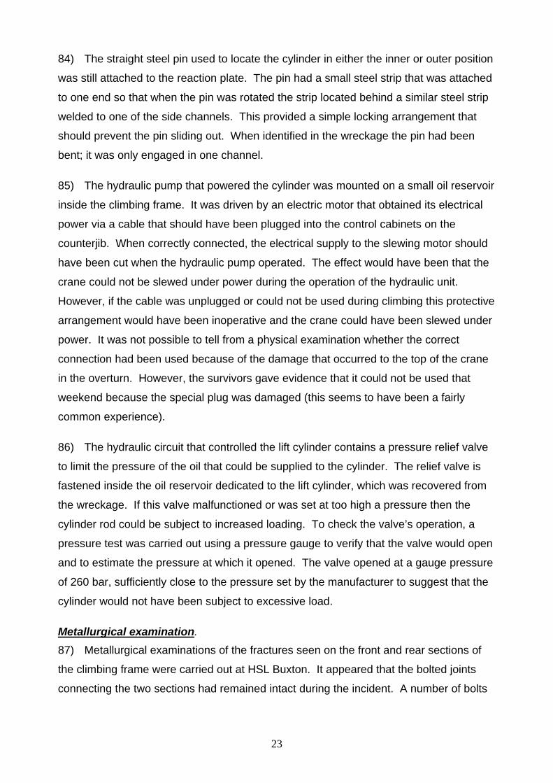
10) The crane slewing module is at the top of the mast. On the underside of this
module is a short mast head section attached to the top of the mast by the same pinned
spigot and socket arrangement used for the crane mast sections. The slewing module
contains a large internal ring gear and motor that is used to rotate or slew the top of the
crane in a horizontal plane. Fixed to the top of the slewing module is the luffing jib, the
counterbalance jib, the A-frame that carried the luffing ropes to enable the driver to vary
the angle of the jib, the control equipment and driver’s cab.

5
The climbing gear 11) At the time of the incident the crane was fitted with a Wolff KWH 20.5 detachable
hydraulic exterior climbing gear approximately 9.3 metres high. Wolff supplied the
climbing gear to Hewdens in 1997. The purpose of this device was to enable the
erectors to insert new mast sections on top of the existing crane mast, thereby raising
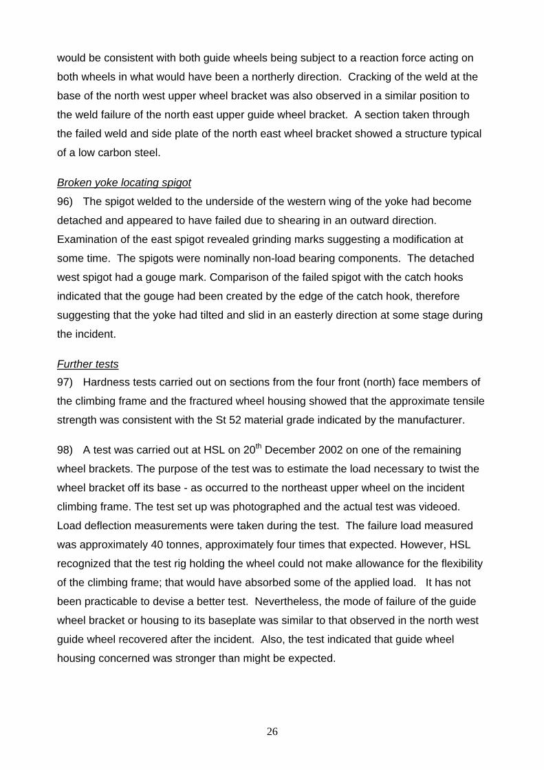
the working height of the crane.
12) The main structure of a KWH 20.5 climbing gear (referred to hereafter simply as
‘the climbing frame’) consists of front and back climbing frame sections bolted vertically
together around the mast of the crane. The principal uprights of the climbing frame are
fabricated from hollow rectangular steel sections 120mm square. The lower part of the
climbing frame is fitted with two sets of four 226mm diameter grooved guide wheels.
The lowest set are fitted to the base of the frame and the upper set are fitted 3.25m
above that. The frame moves up and down the top mast section of the crane guided by
these wheels. They run on the corners of the mast sections when in use. They are
intended to keep the frame in line with the mast of the crane. Nominally there should be
2mm clearance between the wheels and the mast legs. They transmit any forces acting
on the frame onto the mast.
13) The frame contains a long stroke hydraulic cylinder mounted vertically at the rear.
This performs the lift. Power to the hydraulic motor is intended to be supplied via a
special socket in an electrical panel on the machine deck. When used, this should
prevent the crane driver from slewing or luffing the crane during the use of the hydraulic
cylinder.
14) A piston rod protrudes down from the hydraulic cylinder in the climbing frame and
is attached to a horizontal cross head - referred to as the ‘yoke’ - by a large swivel
bearing. This ‘yoke’ appears to have two short ‘arms’ protruding from the top on each
side. The yoke isn’t positively attached to the mast. There are two short welded
locating spigots projecting down from the underside of each ‘arm’. These engage in
holes in the catch hooks welded to the rear legs of the mast. They help ensure that the
yoke sits in the correct position. The catch hooks act as reaction points for the hydraulic
piston rod enabling it to exert an upward force and lift the top of the crane when
required. The catch hooks on a mast section slope downwards towards the middle of its
rear face. This helps to centralise the yoke as it engages on the mast.

6
15) The hydraulic cylinder is fitted with a special trolley on steel wheels (the piston
traverse carriage). This trolley can be moved backwards and pinned in place by a
30mm diameter steel pin to avoid the cylinder fouling the catch hooks and other
projections on the mast when the cylinder rod is retracted. The steel pin is moved to the
other side of the cylinder to hold it towards the mast during a climbing operation.
16) On the front face of the climbing frame there is a platform (traverse carriage
platform) on which each new mast section has to be located. Above the platform there
is a large opening in the climbing frame to allow the erection crew to insert the new
tower section. The new mast section sits on a carriage (sometimes referred to as ‘the
tray’) with four small wheels located on the platform and is moved through the opening
at the appropriate point of the climbing operation. The wheels run on rails built into the
climbing frame.
17) The climbing frame is equipped with upper and lower working platforms to facilitate
fitting and operation. When required for use, the climbing frame is lifted into place and
attached to the underside of the slewing module (mast head section) by steel pins.
When assembled but not in use the climbing frame is usually detached from the mast
head and parked above the highest tie to the structure. Figure 3 gives a schematic
explanation of the climbing frame key parts; Figure 4 illustrates the arrangement of the
guide wheels on the corner of a mast leg.
18) The climbing frame was not erected on TC3 in September 1999 when that tower
crane was thoroughly examined by an independent competent person. It later
transpired that no certificate of thorough examination was available for the climbing
frame. Also, no maintenance records for the device have been available for inspection.
Tower cranes 2 and 3 were first climbed using the climbing frame in January 2000.
Further climbs took place in February, March and April. The erection supervisor tested
the crane and issued a certificate (after completing these climbing operations) indicating
that the crane was ready to be brought back into use.
Description of the tower crane climbing operation 19) Figures 5-7 show a typical Wolff luffing jib tower crane and climbing frame during a
special demonstration climbing operation arranged by Hewdens at HSE’s request; key
parts are labelled. The models of crane and climbing frame used for the demonstration

7
were similar to those involved in the incident at Canada Square (but different models)
and the mast height was kept as short as practicable.
20) To ‘climb’ the crane a gap of more than 4.5 metres has to be created between the
upper part of the crane mast and the top of the crane. At the start of the operation, the
new mast section to be inserted is lifted up and placed on a platform projecting from the
climbing frame in readiness. When a sufficient gap has been created by extending the
hydraulic piston rod the new mast section is rolled into that gap (Figure 7) and attached
to the crane top (mast head). Then it is lowered onto the top of the existing mast by
retracting the hydraulic piston rod and pinned to the existing mast.
Erecting the climbing frame
21) The rear half of the climbing frame is lifted in place by the crane and secured to the
lower part of the tower top. The second half is then lifted, secured to the tower top and
the two halves are then pulled together with a chain block and bolted. The tolerances
are tight; in particular the manufacturer has indicated that, when new, there is 2mm gap
between the guide wheels and the mast. Erectors reported that they sometimes
struggled to bring together and bolt the two halves. If one of the bottom set of guide
wheels was slightly off the corner of the mast (say 4-5mm) force would sometimes be
used to move it into place.
Locating the climbing frame onto the catch hooks and taking into operation 22) At the start of each climbing stage the yoke is adjusted so that the spigots
projecting from the underside of the yoke arms are positioned into the holes or slots of
the catch hooks at the rear of the mast. The adjustment is made by extending or
retracting the hydraulic cylinder piston rod and pulling the cylinder assembly towards the
mast so that the spigots seat properly in the catch hooks (see Figure 8). The hydraulic
piston traverse carriage should then be pinned to lock it in position close to the mast.
Lifting a new mast section to the climbing frame
23) The new mast sections to be inserted are stood vertically in a convenient position
on the ground below. The crane is used to lift a new mast section onto the traverse
carriage of the platform projecting from the front of the climbing frame (see Figure 6).
8
‘Balancing’ the crane
24) The jib is then checked, if necessary, to ensure it is square with the mast (jib
pointing directly forwards) and the slewing drive brake engaged; the crane should not be
slewed during the climbing operation while the piston rod is extended. The angle of the
crane jib is then adjusted to set the crane at the typical ‘balancing’ radius for the crane.
This is the approximate position at which the forward overturning moment is balanced by
the backwards overturning moment. When climbing, the balance point for the crane is
located at the rear of the mast in a vertical line through the hydraulic cylinder.
25) With saddle (horizontal) jib tower cranes the balancing operation is carried out
using a balance weight suspended from the crane hook attached to a trolley that runs on
the jib of the crane. If a luffing jib crane is to be climbed it is possible to use the self-
weight of the crane jib (including the hoist rope and hook block) to balance the crane
instead. Therefore, a luffing jib crane like the Wolff 320BF need not be balanced with a
balance weight. If no balance weight is used the jib radius will need to be greater than if
a balance weight had been suspended from the crane hook. The manufacturer’s
instructions were geared towards the use of a balance weight. However, the general
practice at DS2 was not to deploy a balancing weight when climbing cranes. There was
no advice in the manufacturer’s manual on the typical radius for balancing the crane
without a balance weight (see paragraph 127).
26) The pins joining the top of the mast to the mast head under the slewing module
have to be removed by hammer. The practice is to assess the ‘balance’ of the crane by
checking the alignment of the spigots on top of the mast and the sockets of the mast
head as the hydraulic piston rod was extended by a small amount. The control lever for
the up/neutral/down valve of the hydraulic cylinder unit is operated from the top access
platform. Checks are then made on all four corners of the mast. If the erectors judge
that the two sections were vertically aligned (free float) the crane was considered to be
‘balanced’ and climbing could begin. If they were not exactly aligned – that is with the
socket rubbing on the spigot - the process would start again. The radius of the crane
would be adjusted by luffing the jib up or down and the erectors would raise the crane
top slightly to re-assess balance. When the erectors judged the spigots and sockets to
be aligned they would assume the crane was balanced.

9
27) The exact balancing radius will be affected by conditions on the day including:
• the existence of local wind effects including speed and direction
• the verticality of the mast (which changes with the height above the last building tie)
• variations in judgments about the correct alignment of the top mast section and crane top (mast head)
• frictional forces.
28) The manufacturer’s manual advised that the climbing frame might only be used in
wind speeds up to 45 km per hour (approximately 28 miles per hour). Hewdens had
decided to work to a lower maximum wind speed of 20 mph, although there appeared to
be some confusion among the erectors about this. In practice, this wind speed could
only be taken into account at the start of a climb, before the crane top was separated
from the mast. Both wind speed and direction are likely to vary during a climbing
operation.
29) As the free height of the crane increases above the highest tie to the structure the
mast tends to lean backwards because the hydraulic cylinder is at the rear. The higher
the crane above the topmost tie the greater the degree of lean: this will affect the radius
at which the crane is balanced.
30) ‘True’ balance would ensure that the forward overturning moment is exactly
balanced by the backwards overturning moment of the crane. In this position, the force
acting on the guide wheels should, in theory, be zero. The balance changes during the
climbing operation, e.g. as the new mast section is moved into the gap in the climbing
frame. When the supervisor is satisfied that the crane is balanced the crane driver is
meant to switch off power to the slewing motor and luffing motor.
Raising the hydraulic piston rod for climbing
31) The hydraulic piston rod is then extended, lifting the top of the crane to create an
opening large enough to admit the new mast section. The gap created between the top
of the mast and the mast head below the slewing module is now approaching 5 metres.
The lift takes around 20 minutes and would normally be done in one continuous
extension of the piston rod.

10
Inserting the new mast section
32) One of the erection crew then goes out onto the traverse carriage platform and
pulls the new mast section on its tray into the gap created. The piston rod is then slowly
retracted to lower the four sockets of the mast head onto the spigots of the new mast
section. As a consequence, the tray holding the new mast section tends to sit down on
the spigots at the top of the crane mast – there are pockets on the underside of the tray.
Four temporary hardened steel pins should then be inserted to suspend the new mast
section from the top of the crane (the mast head section). The piston rod is then
extended again to lift the new mast section clear of the tray. The temporary pins are
slightly smaller than the 70mm diameter permanent pins and have a convenient handle.
However, a practice had developed among some of the Hewdens crews to use short
lengths of scaffold tube about 18 inches in length and 50mm in diameter. The intention
was to provide greater freedom of movement for the new mast section when suspended
from the crane top before making a permanent connection to the mast.
33) The tray is then withdrawn and pinned back to the front platform. The new section
is now being suspended from the underside of the mast head roughly 0.5 metres above
the top of the mast. The next stage is to lower the top of the crane again so the sockets
on the underside of the new section engage with the four spigots on top of the mast.
The new section is then secured with eight permanent pins. The temporary pins at the
top of the section also need to be replaced.
Preparing for a new climb
34) Each climbing or jacking procedure for each new mast section added takes about
1¼ hours from start to finish under normal conditions. Before the procedure can be
repeated, the yoke must be seated on the next set of catch hooks. The yoke assembly
attached to the end of the piston rod is moved out horizontally, clear of the mast, to
prevent it fouling any projections. The piston rod is then fully retracted back into the
hydraulic cylinder to raise the yoke up to the next set of catch hooks. When the yoke
has been seated on these higher catch hooks and the upper fixings checked, the crane
can be slewed - if necessary - to pick up the next mast section.
11
Background Circumstances leading up to the incident
35) By 18 May 2000 the steelwork erected around the core of building DS2 had
reached above the 19th level, just below tower cranes TC 2 (at the SE corner of DS2)
and TC3 (at the NW corner of DS2). As one of the main functions of these cranes was
to lift steel beams and columns for the steel erection sub-contractor, the height of the
cranes had to be raised to enable the contractor to continue work. TC1, positioned
inside the central concrete core also had to be raised in height.
36) A climb was arranged for TC2 and TC3 over the weekend of 20 and 21 May, with
some preparatory work to be done on the Friday. Hewdens erectors had already used
the external climbing frame on these two cranes to ‘climb’ TC 2 and TC3 in the previous
few months.
37) Two crane erection crews were sent to site to ‘climb’ six new mast sections (4.5
metres tall) into both TC2 and TC3. The intention was to raise the height of both cranes
by about 27 metres. On Thursday 18 May the first erection crew of five arrived on site to
raise the height of TC1. This work was finished in the early hours of the following
morning.
38) At about 7.30am on Friday 19 Michael Whittard and his four erectors arrived on
site. Their first job was to fit tie collars to TC2 & TC3. These were to secure the top part
of the crane mast to the steelwork at level 17/18. The collars went around the mast and
were pinned to a steel beam of the building. The climbing frame had to be moved from
its parked position at the existing tie collar and relocated above the new collar.
39) On Saturday 20 May both erection teams arrived at around 7am. The two
supervisors discussed what had been done so far and what had to be done next. It
seems that neither of them had a method statement, although they were both familiar
with climbing these tower cranes. They decided to use a radius of between 30 and 31
metres for balancing the crane.
40) Michael Whittard’s team unloaded six mast sections for TC2 from the vehicles that
had brought them to site and started the process of climbing them into that crane. The
other team unloaded mast sections for TC3 and then fitted a new hoist rope to that
crane because the existing rope was no longer of sufficient length.

12
41) In May 2000, TC2 and TC3 each had an external climbing frame. Neither was
properly connected to the designated power supply point on the machine deck because
the special plug for the power cable to the hydraulic unit was damaged (see paragraph
85). This meant that the manufacturer’s arrangement for preventing powered slewing of
the crane during a climb was not operational.
42) The driver of TC3 that day, who normally worked as the driver of another tower
crane on DS2, was new to climbing; he just followed the supervisor’s instructions. He
luffed out the crane jib to the radius suggested without using a balance weight, then hit
the red button on the control panel to isolate the controls from the rest of the crane and
applied the slew brake. He expressed some concern about the vibrations and erratic
movement he experienced during climbing. After discussion with the supervisor, he
decided to come down from his cab between each climb, as he was not needed to
operate the crane. When the new mast section had been brought into the climbing
frame the jolting would stop. The driver said that the piston would stop and start
repeatedly as the supervisor closely controlled the descent of the new mast section
ensuring it was aligned with the top of the mast.
43) The driver thought the climbing frame was not in as good a condition as those he
had seen elsewhere. It looked well-used, dirty and needed a lick of paint. But he saw
no leaking oil. He knew how variable the wind could be around DS2 and, without an
anemometer, he relied on the supervisor’s experience to tell him if it had become too
windy.
44) In the late afternoon, the wind speed on the east side of DS2 where TC2 was
situated was judged to be too great to continue climbing; Michael Whittard decided to
suspend that work and his crew moved onto TC3 to assist the other crew with the
climbing of TC3. By the end of work late on the Saturday, four new mast sections had
been climbed into TC2 and three sections into TC3, before that too was ‘winded off’.
45) There seems to be some confusion about how TC3 was left the night of 20 May. It
has been suggested that the crew had some difficulty with the electrically operated slew
brake and may have put the crane into free slew at the end of the day by lifting the
manual clasp on the slew motor outside the cab. However, witnesses stated that if this

13
had happened it would have been detected the following day quite quickly and corrected
and physical evidence suggests the brake was ON (see paragraph 71).
46) On Sunday 21 May 2000, Michael Whittard’s crew started work at DS2 around 7
am to complete the climbing of TC2. Peter Clark, an experienced crane driver who
normally worked on TC3, took over the crane driving duties. It appears that he had been
involved in previous climbs of TC3 with Michael Whittard. After lunch, they began to
climb in the last three sections of TC3. The other erection crew had been asked to
carry out crane erection work at another site in west London and so they were not at the
DS2 site that day. They only returned after they were informed of the incident.
47) The ‘climb’ of the last mast section proceeded as usual, after balancing the crane.
Michael Whittard (the supervisor) and Martin Burgess were working on the upper
platform of the climbing frame and two other erectors were working on the lower platform
of the climbing frame. Peter Clark stayed in his cab after helping to balance the crane at
the start of the climb. A trainee erector had been asked to work at ground level to sling
any load that needed lifting, such as the new mast sections.
Details of the incident – key events The collapse
48) At about 3.50 pm, the two erectors on the lower platform of the climbing frame
moved the last mast section from the transverse carriage platform into the frame.
Michael Whittard, on the top platform of the climbing frame, operated the lever
controlling the hydraulic cylinder to retract the piston rod, lowering the mast head onto
the new mast section. Martin Burgess used short lengths of scaffold tube about 50mm
in diameter (temporary pins) to suspend this new mast section to the bottom of the mast
head. Michael Whittard then operated the control valve of the hydraulic cylinder to
extend the piston rod again and lift the crane top (and the new mast section suspended
from the mast head) so the carriage (or tray) used to slide the new mast section into the
frame could be moved out of the way. The piston rod would have been approaching full
extension at that point.
49) One of the erectors pushed the tray back onto the front platform; the tray had to be
secured in place on the platform. At this stage it is estimated that the erection crew
were around 15 minutes away from completing the basic climb of this last section; they
14
had only to lower the new section onto the top of the crane mast and insert all the
permanent pins. Then the crane would have been made ready for use and tested.
50) Suddenly, while he was still on the transverse platform, the erector noticed that
one of the guide wheels was moving laterally around one of the legs of the mast. He
thinks this was the upper north east guide wheel – the front upper guide wheel nearest
DS2. The top of the crane was either about to be lowered or Michael Whittard had just
started to lower it. There would have been a gap of the order of 0.5 metres between the
top of the mast and the bottom of the new mast section before lowering started.
51) The two erectors by the lower platform jumped onto the metal ladder within the
mast and managed to move down the mast a short way. They looked up towards the
erection supervisor, Michael Whittard, who expressed surprise. The climbing frame now
seemed to be tilting about the NE leg. One of the erectors reported hearing sharp
popping or banging noises a bit like gun shots but it isn’t clear at what stage these
occurred.
52) The mast started shaking violently. The two erectors managed to cling on to the
ladder within the mast. Eventually, the mast stopped shaking. The climbing frame,
hydraulic cylinder, new mast section and the top of the crane had overturned and fallen
to the DS1 site about 120 metres below. Michael Whittard, Peter Clark and Martin
Burgess had fallen with the top of the crane and were fatally injured. The crane mast
was left standing with the two survivors holding on to the metal ladder within. They
managed to make their way across the uppermost building tie and down to the ground in
a state of distress. The last member of the crew, the trainee, was uninjured by the fall of
the crane top but he was also found in a distressed state.
53) About five minutes before the incident occurred, a site worker happened to be
taking photographs of the DS1 and DS2 sites from the platform at West India Quay
Docklands Light Railway Station. These photographs show that there was no mast
section on the traverse carriage platform at the time they were taken. Therefore, it
appears that at this point the last mast section had already been moved within the
climbing frame. They also show the crane jib was pointing north - as it should have
been – and not slewed.

15
54) The trainee erector on the ground, had his back was turned to the crane and did
not witness the position of the jib prior to the collapse. No other witnesses managed to
recall the position of the jib with any certainty.
55) The two survivors reported that:
• the crane was not slewed (rotated horizontally) or luffed immediately prior to the
incident - they believe the jib was parallel to the DS2 building
• they could recall nothing unusual about the last climb although there was some
difficulty getting the previous mast section in place - a pinch bar was used to force it
in place.
• although there was no anemometer fitted to this tower crane they are sure that it was
not windy (one of the erectors told the coroner’s inquest that he would have felt the
climbing frame move if the wind speed had been significant)
• there was a slight bow in the climbing frame between two of the bolts that join the
two halves together; this bow was about half way up on the east side a couple of
metres above the top set of guide wheels and seems to have been between 6” and
12” long and up to 1” wide.
56) One of the erectors suggested that the bow mentioned above had been caused by
lifting chains when one half of the climbing frame had been lifted roughly on a site. It
seems to have been present for some months. The survivors reported that the two parts
of the climbing frame were adequately bolted together at this point, making allowance for
the bow. Apparently, the supervisor had sought advice from Hewdens office some time
before that weekend but it was not judged to be a serious defect and the erectors
continued to use the climbing frame.
Outline description of the wreckage 57) Figure 9 shows the general area of DS1 and DS2 with the mast of TC3, the
wreckage and damaged steelwork of the DS 2 structure. Figure 10 is a plan of the area
around the DS2 site illustrating the position of the wreckage. Figures 11-12 are closer
views of the wreckage. The crane top did not fall straight back on a north-south line but
at an angle of approx. 30 degrees to the west of the building. The main part of the crane
top landed across the boundary of DS2 with DS1. The top of the crane had penetrated
the ground level car park of DS1. The end of the 50-metre jib fell across the site

16
boundary and a public road, landing on a single storey building housing an exit staircase
from an underground area. The hook block and hoist rope went further, missing a
mother and her young child in Canada Square and landing on the paved area outside
the Canary Wharf tower at No.1 Canada Square.
The investigation 58) Two inspectors went to the site on the evening of the incident. Arrangements were
agreed with the principal contractor to leave the wreckage in place undisturbed. An
inspector met the survivors but they were in a state of shock and could not be
interviewed at that point. The following day, a formal investigation was begun with a
specialist engineering inspector. Following an initial assessment, staff from the Health
and Safety Laboratory (HSL) were asked to join the investigation team in order to carry
out a thorough examination of the scene. HSE inspectors then met detectives from the
Metropolitan Police and agreed that a joint Metropolitan Police/Health and Safety
Executive investigation would be undertaken, in line with the Protocol for Work-Related
Death. Subsequently, an HSE lifting specialist joined the investigation. HSE and
Metropolitan Police detectives then began interviews with various witnesses.
59) Initially, HSE had to agree a plan with the contractors to remove or make secure
damaged steelwork. Once a suitable plan had been developed, recovery work on the
main area of wreckage began on 25 May. The HSL team oversaw the operation to
ensure that potential evidence was not lost or damaged. As items were lifted free they
were catalogued by HSL, placed in a holding area and subsequently despatched under
escort to HSL’s site at Buxton; in a few cases smaller items were taken to HSL’s
laboratory at Sheffield. Video recordings and photographs were taken during the
recovery. The HSL team also carried out careful searches for other parts of the crane
and those parts found were catalogued. The team worked on site for two weeks during
which time most, but not all, the relevant parts of the crane were recovered. Some parts
were extracted from the debris in the basement areas of site DS1 at a later stage of the
recovery operation and subsequently removed to HSL’s Buxton site for examination.
Initial examination of damaged components by HSL 60) The main components recovered from the wreckage were:
• The climbing frame and associated parts that had broken free
• The slewing module and machine deck (counterjib)
17
• The new mast section (that is the mast section that had been moved from the front
platform into the climbing frame)
• The top mast section
• The second mast section
• The luffing rope drum
• The ‘yoke’ and a broken spigot
• The lift cylinder
• The slewing motor and brake (which was recovered later).
61) The climbing frame bore a plate describing the type as KWH 20.5 and giving the
year of construction as 1997. It listed the manufacturer’s name, address, telephone
number and fax number and had a CE mark.
62) HSL discovered that the crane had a basic electronic in-built memory (datalogger)
to record crane movements. Enquiries were made of Wolff, who provided information
about its location on the machine deck. The ‘datalogger’ was found in the parts of the
wreckage taken into HSE’s possession but it had suffered significant damage and the
battery maintaining its memory had been lost. Apparently, it was not designed to record
the crane’s movements chronologically during the climbing operation.
The climbing frame
63) The climbing frame had sustained very substantial damage and had to be cut
further to enable its recovery. The four cross members that had made up the lower part
of the front or northern face of the climbing frame had become detached at some stage.
Figure 13 shows the relative positions of the four members on the front face of the
climbing gear.
64) The upper part of the front face is open to allow the new mast section to be moved
into position at the top of the existing mast. As the uppermost section of mast was
located inside the lower part of the climbing frame at the time of the collapse, each of the
four members must have become detached from the climbing frame at one or both ends
as the collapse progressed.
65) All eight guide wheels of the climbing frame were identified among the recovered
material on site. Seven of them were still attached to the climbing frame but the eighth
wheel (the north east upper wheel) had become detached from the frame at some stage.

18
The various parts of the north east upper wheel assembly were found on an
approximate line between the mast and the main area of wreckage close to the main
area of wreckage. Both the north east and north west upper guide wheel housings had
sustained plastic deformation (stretched and permanently deformed). The north east
wheel had twisted clockwise (to the east) and broken free; the north west wheel had
twisted anticlockwise (to the west) and suffered substantial cracking but remained
attached. The remaining six wheel housings appeared to be undistorted. Reference to
the north east and north west is based on the position of the crane with the crane jib
pointing approximately to the north.
66) The detached lower horizontal and lower diagonal members of the front face of the
climbing frame and the guide wheel were found in different parts of the site known as
DS1. Both members had a deep indent towards what would have been their eastern
ends prior to the collapse. It was apparent that the two indents lined up very well at a
position that would have been approximately 270mm from the inside of the north east
leg of the climbing frame. This suggests that both indents were created simultaneously.
As the members were found in different places this suggests that the damage must have
occurred when both were still attached to the climbing frame, rather than in the collapse.
67) The lower horizontal member left a deep gouge mark in the concrete surface of
DS1. The gouge lined up with the main area of wreckage suggesting that, like the upper
two cross members, it had remained partially attached to the climbing frame and had
only broken free when the crane top struck the ground. One end had failed completely
through the weld and appeared to be typical of failure due to an overload. The other end
had failed through the weld connecting a small end plate to the climbing frame. The
visible areas appeared to have failed due to overload. The lower diagonal member was
found on the access road by the canteen, north of the crane. Both ends appeared to
have failed due to overload.
68) The upper horizontal member had become detached at its eastern end during the
incident but only broke away from the western side of the climbing frame during the
recovery operation. The upper diagonal (the last of the four cross members of the
climbing frame) had become detached at its western end but remained attached to the
eastern side of the climbing frame. The top horizontal member was found later at the

19
bottom of the hole created by the crane counterweights penetrating the concrete ramp
on the DS1 site.
The slewing module 69) The slewing module was recovered largely intact from the main area of wreckage
but the slewing motor and brake, which had been attached to the module, had broken
away during the incident. Before removal it was noted that the slewing ring, which
enables the crane to rotate, had turned approximately 40 degrees from the front-facing
position. During recovery or transport to HSL Buxton the slewing ring rotated almost
back to the front facing position.
70) The four sockets in the underside of the slewing module (on the lower part of the
mast head) had sustained damage. In particular what had been the north east corner
socket had split open. Part of a scaffold tube was found within one of the mast head
sockets and short sections of scaffold tube were noticed in the wreckage (see Figure
12).
Slewing motor and brake
71) The slewing motor (Figure 14) was not recovered from the wreckage until a few
weeks after the incident; it was trapped in debris below DS1. It was examined at HSL’s
laboratory. The metal clasp on the front of the motor cowling is understood to be the
manual override for the electromagnetic slewing brake. With the clasp in the position
shown the brake is understood to be in the ‘on’ position. Although unlikely, it is not
possible to rule out the possibility that the clasp was disturbed in the recovery of the
motor, as this was not witnessed by HSE. A test carried out in the HSL laboratory to
check the torque needed to overcome the brake measured it at 124 Newton Metres
which is consistent with that specified in the crane manual for a Wolff 320 BF. That
torque is designed to resist rotation of the crane caused by moderate wind loading.
New mast section
72) The new mast section found within the remains of the climbing frame had
sustained substantial crushing damage. The original square cross section had been
distorted to a lozenge shape. There was a small plate welded to one of the legs of the
mast section describing the type of mast section as a TV 20.4.
20
73) On inspection, it was found that the paint on the insides of the sockets at the
bottom of the section had been scraped in parts and there were traces of grease
present. This suggested that, at some time, spigots from another mast section had been
inserted into these sockets. However, it appeared that the section had not been used
before, a point confirmed by Hewdens. If, at the time of the incident, the sockets had
been engaged with the spigots at the top mast section of the crane HSL would have
expected to find substantial damage – as was found on the slewing module (mast head)
sockets – but this was not the case. Therefore, the marks were probably caused in
storage or transit.
Top mast section 74) Before removal of the top two mast sections from the top of the mast, the legs were
labelled so their orientation as fitted to the mast was recorded. The top mast section had
a small plate welded to one of the legs stating the type of mast section as a TV 20.4.
75) The upper part of two of the legs, the legs believed to have been facing north east
and south east, had been bent from mid-height. The north east leg had been bent to the
south by approximately 200mm and the south east leg had been bent to the west by
approximately 400mm. HSL judged that the pattern of damage was a consequence of
the diagonal bracing members’ configuration. This bracing provided substantial
stiffening that would resist bending in one direction. For instance, if the north east leg
had a load applied from the north the leg will bend more readily than if the load was
applied from the east. This is because a substantial part of the load applied from the
east would be transmitted down the diagonal bracing on the north face of the mast
section and only a small part of the load would be resisted by bending of the mast leg. If
a load was applied from the north no similar bracing was present and the load has to be
resisted totally by the mast leg (see Figures 15 and 16).
76) As the mast sections were believed to be new, a detailed examination of all the
marks on the top section was made. It is likely these were made at the time of the
overturn. HSL measured the width of the mast sections by tape as two metres (within
the limits of the method of measurement). This met the manufacturer’s specification,
Two distinct pairs of deep gouge marks were found, one pair running from the outer
corner near the top of the north east leg on its east face approximately 300mm down
from the top of the leg and the other running from the outer corner approximately one
21
metre from the bottom of the south east leg on its south face. Figure 17 shows a guide
wheel being offered up to the gouge marks on the south east leg, illustrating how well
the marks on the south east leg match a guide wheel. The marks suggest that the guide
wheel moved up the south face of the leg after coming off the corner of the mast.
77) The spacing of the marks suggests they were caused by guide wheels after they
slid from around the corners of the mast. If so, HSL has estimated that the bottom of the
new mast section was still approximately 350 to 400 mm above the top of the mast at
the start of the overturn. The outer corners of all four legs had sustained scraping
damage at different positions along their length. HSL believes that this damage was
caused when the climbing frame slid from around the mast section. There were also a
number of marks on the tops of the location spigots of this upper mast section. These
could have been caused during the incident or when this mast section was loaded in
place.
Second mast section
78) The second mast section recovered from the top of the mast also bore a plate
describing the type as a TV20.4. It had suffered minor damage to the mast legs and
some buckling of the platform and handrail. The catch hooks on this section would have
supported the yoke of the climbing frame. Figure 18 shows the tops of the catch
hooks.
Luffing rope drum
79) The luffing rope drum was largely undamaged and still held two layers of luffing
rope, one complete (inner) and one partial (outer). There were 25 turns of rope in the
inner layer and the rope in the outer layer measured 53m. From this it was estimated
that the overall length of rope left on the drum was approximately 106m.
Yoke 80) The side plates on the top of the yoke to which the lower end of the lifting cylinder
rod had been attached were damaged. Figure 19 shows the west side of the damaged
yoke recovered from the wreckage. There was a pronounced indent in what would have
been the side face of the west leg. A small spigot 50mm in diameter by 30mm long had
been welded on the underside of each of the two arms of the yoke. The spigots would
have located in the slots in the top faces of the catch hooks. The western spigot had

22
become detached at some stage and was found approximately 5 metres from the
bottom of the crane mast. The proximity of this spigot to the base of the crane TC3
suggested to HSL that it broke away from the yoke at an early stage of the incident. The
second spigot remained attached to the eastern arm.
Hydraulic cylinder
81) The lift cylinder body had survived the incident without sustaining any great
damage but the cylinder rod had assumed an ‘S’ shaped buckled form. This suggests
that the piston rod would have been loaded to have produced that buckled shape. It is
unlikely that it would have received this damage when it struck the ground. The lateral
distortion of the cylinder rod was estimated to be over 3 metres (Figure 20 illustrates the
extent of the distortion).
82) The reaction plate against which the cylinder thrusts upwards to lift the crane top is
located in the climbing frame approximately half way up its height. The plate contains a
slot through which the cylinder body is passed. During the climbing part of the
operation, when thrust would be applied, the cylinder would be held at the inner end of
this slot. When the cylinder was being raised to engage in the catch hooks of the next
mast section the cylinder would be held at the outer end of the slot. A thick steel collar
attached to the lower end of the cylinder body thrusts against the underside of this plate
to transmit the force provided by the cylinder to lift the crane top. On inspection it was
observed that there were two overlapping indentations in the plate corresponding to the
two positions, inner and outer, of this collar. The outer indent was pronounced –
between 1mm and 2mm deep tapering to nothing at the outermost edge.
83) The indent at the inner (northern) position was about 0.5mm deep and was most
likely to have been produced during successive climbing operations, when large static
forces would have been present. When the cylinder was at the southern end of the slot
there should have been no thrust present and so no indent would have been expected.
It may have been caused when the crane top impacted with the ground, causing the
collar on the lift cylinder to impact on the plate. Alternatively, the indent might have been
caused by the lift cylinder not being correctly positioned during the climbing sequence or
the cylinder moving to the southern position during the sequence.
23
84) The straight steel pin used to locate the cylinder in either the inner or outer position
was still attached to the reaction plate. The pin had a small steel strip that was attached
to one end so that when the pin was rotated the strip located behind a similar steel strip
welded to one of the side channels. This provided a simple locking arrangement that
should prevent the pin sliding out. When identified in the wreckage the pin had been
bent; it was only engaged in one channel.
85) The hydraulic pump that powered the cylinder was mounted on a small oil reservoir
inside the climbing frame. It was driven by an electric motor that obtained its electrical
power via a cable that should have been plugged into the control cabinets on the
counterjib. When correctly connected, the electrical supply to the slewing motor should
have been cut when the hydraulic pump operated. The effect would have been that the
crane could not be slewed under power during the operation of the hydraulic unit.
However, if the cable was unplugged or could not be used during climbing this protective
arrangement would have been inoperative and the crane could have been slewed under
power. It was not possible to tell from a physical examination whether the correct
connection had been used because of the damage that occurred to the top of the crane
in the overturn. However, the survivors gave evidence that it could not be used that
weekend because the special plug was damaged (this seems to have been a fairly
common experience).
86) The hydraulic circuit that controlled the lift cylinder contains a pressure relief valve
to limit the pressure of the oil that could be supplied to the cylinder. The relief valve is
fastened inside the oil reservoir dedicated to the lift cylinder, which was recovered from
the wreckage. If this valve malfunctioned or was set at too high a pressure then the
cylinder rod could be subject to increased loading. To check the valve’s operation, a
pressure test was carried out using a pressure gauge to verify that the valve would open
and to estimate the pressure at which it opened. The valve opened at a gauge pressure
of 260 bar, sufficiently close to the pressure set by the manufacturer to suggest that the
cylinder would not have been subject to excessive load.
Metallurgical examination. 87) Metallurgical examinations of the fractures seen on the front and rear sections of
the climbing frame were carried out at HSL Buxton. It appeared that the bolted joints
connecting the two sections had remained intact during the incident. A number of bolts

24
securing the two sections had to be cut to enable different parts of the climbing frame to
be recovered. It was decided to carry out detailed examination of each of the cross
members. The ‘eastern end’ of cross members is that which would have been closest to
the building on DS2; the ‘western end’ would have been furthest from the building.
Top horizontal member at the front of the climbing frame
88) The east end of the top horizontal member had fractured through the weld metal.
Examination suggested the failure had occurred due to ductile fracture. Some of the
welds had resulted in little weld penetration and subsequently a lack of fusion between
the weld metal and the edge of the member.
89) Failure of the west end of the member showed two failure modes. Approximately
25% had failed by a ductile fracture mechanism through the weld metal with the
remaining failure having occurred through the parent material in a fast fracture manner.
Examination of the video taken during recovery confirmed that the upper horizontal
member was still attached to the climbing frame by the outside weld on the western end
and was broken completely during recovery of the hydraulic cylinder. No evidence of
progressive failure was observed. A section taken through the upper horizontal member
showed a structure typical of a low carbon steel in the as-rolled condition.
Upper diagonal member at the front of the climbing frame 90) The western end of the upper diagonal member had failed through approximately
75% weld metal and 25% parent metal. Examination of the matching fracture on the
north west leg of the climbing frame showed signs of mechanical damage caused by
contact from the inside face of the climbing frame leg. The east end had failed around
approximately 75% of the member and therefore remained attached to the east leg of
the climbing frame. The failure mode appeared typical of a fracture caused by ductile
shear. Further examination revealed an indentation on the underside of the cross
member, which suggested the possibility of the member having come into contact with
the chamfered edge of a male spigot on the top of one leg of a mast element. A section
taken through the member showed a structure typical of a low carbon steel.
Lower diagonal member at the front of the climbing frame
91) The west end of the lower diagonal member had failed in a similar manner to the
lower joint of the upper diagonal member, with partial failure through the weld metal and

25
the remaining fracture through the parent metal. Mechanical damage, as observed on
the upper diagonal member, had resulted in crushing of the end of the member. A lack
of fusion was observed between the weld metal and the parent metal of the member on
the bottom side. Examination of the east end of the lower diagonal showed almost
complete failure through the parent metal with a small area of failure through the weld
metal. Areas of mechanical damage were observed, suggesting that the member had
contacted other parts of the climbing frame and or the mast, probably during the
collapse. Examination of the structure showed it was similar to that observed for the
upper diagonal member, typical of a low carbon steel.
Lower horizontal member at the front of the climbing frame
92) Failure of the eastern end of the lower horizontal member had occurred partially
around the weld connecting the end plate of the member to the north east climbing
frame leg and partial tearing of this plate at approximately mid-length.
93) The western end of the lower horizontal member had fractured completely through
the weld metal. Fracture was consistent with an overload failure. No evidence of any
progressive failure modes was observed. A section taken through the member showed
a structure typical of a low carbon steel.
Upper wheel brackets
94) The upper north east wheel bracket had become completely detached and was
found close to the base of an adjacent crane (designated TC5). Failure of the bracket
had occurred through the weld connecting it to the base plate. The failure mode
indicated that fracture appeared to have occurred due to shearing resulting from
torsional (twisting) overload. Failure of one of the side supports had also occurred.
Repositioning of the wheel housing onto the base plate and the bracket showed it had
been subjected to significant forces that had caused twisting and resulted in permanent
distortion (plastic deformation) of the wheel bracket (Figure 21). As a result, the minor
areas of lack of fusion in some areas of the welds were considered insignificant as the
weld had remained intact for sufficient time to cause the distortion.
95) Examination of the north west upper guide wheel bracket also showed evidence of
distortion. This appeared to have resulted from twisting of the guide wheel in the
opposite rotational direction to the north east upper guide wheel bracket. The damage
26
would be consistent with both guide wheels being subject to a reaction force acting on
both wheels in what would have been a northerly direction. Cracking of the weld at the
base of the north west upper wheel bracket was also observed in a similar position to
the weld failure of the north east upper guide wheel bracket. A section taken through
the failed weld and side plate of the north east wheel bracket showed a structure typical
of a low carbon steel.
Broken yoke locating spigot
96) The spigot welded to the underside of the western wing of the yoke had become
detached and appeared to have failed due to shearing in an outward direction.
Examination of the east spigot revealed grinding marks suggesting a modification at
some time. The spigots were nominally non-load bearing components. The detached
west spigot had a gouge mark. Comparison of the failed spigot with the catch hooks
indicated that the gouge had been created by the edge of the catch hook, therefore
suggesting that the yoke had tilted and slid in an easterly direction at some stage during
the incident.
Further tests 97) Hardness tests carried out on sections from the four front (north) face members of
the climbing frame and the fractured wheel housing showed that the approximate tensile
strength was consistent with the St 52 material grade indicated by the manufacturer.
98) A test was carried out at HSL on 20th December 2002 on one of the remaining
wheel brackets. The purpose of the test was to estimate the load necessary to twist the
wheel bracket off its base - as occurred to the northeast upper wheel on the incident
climbing frame. The test set up was photographed and the actual test was videoed.
Load deflection measurements were taken during the test. The failure load measured
was approximately 40 tonnes, approximately four times that expected. However, HSL
recognized that the test rig holding the wheel could not make allowance for the flexibility
of the climbing frame; that would have absorbed some of the applied load. It has not
been practicable to devise a better test. Nevertheless, the mode of failure of the guide
wheel bracket or housing to its baseplate was similar to that observed in the north west
guide wheel recovered after the incident. Also, the test indicated that guide wheel
housing concerned was stronger than might be expected.
27
Design information 99) ‘Technical File’ information was obtained from the manufacturers in Germany. The
main document was a series of analyses commissioned by Wolff in 1995 to check the
structural integrity of the climbing frame and mast section concerned. Subsequently,
Wolff provided further documentary information and meetings were held at Heilbron,
Germany and HSL Sheffield to explore some of the design assumptions.
Tie locations and mast verticality 100) TC3 was tied to the steelwork of DS2 at intervals to restrain free movement of the
mast using tie collars around the mast, three telescopic box section tie bars and steel
legs. The forces imposed on the ties from sideways loading (wind and operational
forces) were calculated by Wolff and supplied by Hewdens to KCB. Using this
information, KCB designed a bracing system to transfer the load on the ties back to the
concrete core of the building. Structural engineers checked the calculations.
Documents showing the calculations for this system were provided by KCB. When
checked after the incident, the uppermost tie was found to be undamaged. The mast
sections above the tie were removed and then rebuilt with the crane being re-designated
as TC9. The non-destructive test (NDT) specialist who examined the welds for the box
ties on 19 May 2000 and after the incident confirms that the tie was free from significant
defect.
101) Witnesses described how the verticality of the mast would be checked with a spirit
level before welding the box section tie in position. When climbing restarted at DS2
towards the end of 2000 the erectors found difficulty in balancing TC2 within the
subsequently agreed constraint (± 2 metres of the theoretical balance radius). On
further investigation, it was found by using a theodolite that the TC2 mast was not
sufficiently vertical. In contrast, a check of the TC9 mast (formerly the TC3 mast)
showed a comparatively small variation in verticality.
Wind conditions 102) The two erectors on the crane who survived the incident reported that there
appeared to be no significant wind immediately before the incident. Wind had affected
climbing work on TC2 and TC3 earlier that weekend, requiring work to stop at times on
one crane or the other. TC3 had no anemometer. It was suggested that the TC3 crew
may have had a hand held anemometer but no evidence was found to suggest one had

28
been used. Also, there was no record of issue, calibration or check of such devices by
Hewdens.
103) Witnesses on the construction site opposite DS2 agreed that it was not ‘windy’.
One crane driver on that site reported a wind speed of about 20kph that afternoon
according to his anemometer. The driver of TC1 said he spoke by radio to Peter Clark,
less than 2 hours before the incident and reported a wind speed at that time of 15-20
kph. However he left his crane about 30 minutes before the incident occurred.
Witnesses do report significant variations of wind speed around the DS2 building
generally. On the Saturday, the wind speed on the east side of DS2 was sufficiently
high for climbing to be suspended on TC2 but on the west side the wind speed was low
enough for TC3 to be climbed. HSL staff experienced similar variations in wind speed
and direction during their detailed investigation on site.
104) A report was obtained from The Meteorological Office about general weather
conditions in the locality on the afternoon of the incident. After considering information
from different local weather stations they concluded that, at the time in the Canary Wharf
area, there would have been a light or moderate wind blowing from the north west 120
metres above ground level. In their opinion, it is unlikely the wind speed would have
exceeded about 17 mph (27 kph). However, there could have been numerous gusts of
around 17-23 mph (27-37 kph) and occasional gusts exceeding 29 mph. The hourly
wind direction would be averaged over the 60 minutes beginning at the time of entry.
105) Further advice was sought on wind conditions around the DS2 structure from the
Building Research Establishment (BRE). Estimates were made of likely wind speed
above ground level in the Canary Wharf area given the Meteorological Office wind
speed measurements. BRE believed that at around 4 pm, the wind would have been
blowing from the north west and the mean wind speed at a height of about 120m (400
feet) would have been light or moderate and is unlikely to have exceeded 17mph.
However, gusts of wind could have been 17-23 mph and could even occasionally have
reached as high as 35 mph.
106) BRE looked more closely at the layout of tall buildings in the Canary Wharf area
(from photos and videos) and considered how these buildings at the DS2 site in Canada
Square would have modified the wind. BRE advised that the wind speed at TC3 would
29
probably have varied from zero up to the maximum estimated gust speed, varying both
in height and over time. At the building DS2, BRE estimates a wind speed of 44-50 kph
(27.5 mph–31 mph) with the possibility of isolated gusts between 55-63 kph (34 mph–
39 mph) but at ground level the wind speed would have been relatively low.
107) The effects of wind flow acceleration around the building could have increased the
estimated windspeed at DS2 to 27.5 mph (44 kph). These estimates are somewhat
higher than the qualitative estimates made by witnesses both on TC3 and the adjacent
site DS5. BRE reported that the wind speeds that were likely to have occurred at the
time of the incident were relatively low and would be expected to occur fairly frequently
in Canada Square. For example, a gust wind speed of between 23.9 and 27.3 knots is
equivalent to a mean wind speed of between 15 and 17 knots – a moderate and fresh
breeze. They advise that most people would probably not describe such conditions as
‘windy’. This wind speed, if present, is likely to have been experienced by the erection
team. At ground level in Canada Square the windspeed would have been approximately
50% of that at the top of TC3 i.e. of the order of 7.5 to 8.5 knots, which is only a gentle
breeze.
108) Some witnesses in the area mentioned that they heard a plane flying above the
crane before the incident. BRE believed that trailing wake vortices were unlikely to have
caused the collapse even if they had intersected with TC3.
Radius of the crane 109) As previously mentioned, a site worker took a series of photographs of the DS2 site
(including the crane designated as TC3) a few minutes before the incident. Close
examination showed eight mast sections in place above the last tie to the building. The
climbing frame was in the raised position above the eighth section and there was no
mast section visible on the platform at the front of the climbing frame. This suggested
that the final mast section had already been taken into the climbing frame at that point.
110) The photographs were further analysed by a specialist laboratory on behalf of the
Metropolitan Police. The assessment of the photographs suggested that the jib radius
was approximately 29.3 metres, with a margin of error of plus or minus 5%. They also
concluded that the jib was parallel with the building at the time the photograph was
taken. An assessment was carried out in conjunction with Wolff after counting the

30
number of turns of rope on the luffing drum. They reported that the jib radius would
have been 28.04 metres.
111) The crane manual for a Wolff 320 BF recovered from the wreckage of the TC3 cab
indicated the balancing radii for different crane configurations. It only gives information
about the balancing radii for a Wolff 320BF where there is a balance weight on the crane
hook. For a luffing jib tower crane, changing the jib radius changes the moment about
the hydraulic cylinder (the balance point during climbing) created by the mass of the jib
(and associated parts) being moved towards or away from the balance point. However,
moments created by the counterbalance weights, the weight of the A frame and the
counterjib remain fixed.
112) HSL estimated the radius at which the crane would be balanced when no balance
weight was available would be about 29.4 metres. This involved making simplified
assumptions using the standard masses of parts shown in the crane manual. Wolff
subsequently assessed the theoretical jib radius as 31m without a balance weight.
Analysis of loads acting during the climbing sequence 113) HSL has analysed the loads likely to act on the climbing frame and mast during
climbing, including the deadweight and overturning moments forwards and backwards.
The deadweight is the weight of the individual crane parts and is fixed but the
overturning moments can vary. The essential part of the climbing operation is the
requirement to balance the crane i.e. to position the centre of gravity of the crane top
directly on the centreline of the lift cylinder. The overturning moments will change as the
climbing operation proceeds and these must be reacted or counteracted by the guide
wheels acting on the mast.
114) HSL considered that the main overturning moments would be affected by the
following:
• failure to adopt the correct balancing radius initially and any luffing of the jib
• rearwards deflection of the mast when the hydraulic cylinder is fully extended (the
standard tolerance for vertical alignment given by the manufacturers for this crane is
1 in 1000)
• moving the new mast section into the mast
• guide wheel friction from non-rotation and sliding of the guide wheels
31
• wind loading, including changes after achieving initial balance
• dynamic effects such as juddering of the lift cylinder and distortion that may be
present in the frame.
Structural analysis 115) HSL reviewed the series of analyses carried out in 1995 on behalf of Wolff to check
the structural integrity of the climbing frame and mast section of the type used in the
crane involved in the incident. The analyses considered the frame and mast section
separately and a number of different load combinations. A design maximum overturning
moment of 300kNm had been used. At this loading the highest stressed part of the
frame was shown to be at the top of the frame. This analysis confirmed that the
stresses would not exceed two thirds of the yield stress of the grade of steel used in the
frame members i.e. the safety factor of 1.5 used by the designers was satisfied.
116) To check certain features of these analyses, HSL decided to undertake
independent analyses taking various factors into account using Wolff’s structural
drawings of the KWH 20.5 provided to HSE. A finite element analysis model was
commissioned containing both the mast and the climbing frame. This analysis is a
computer-based method of structural analysis that is widely used in industry. It was
used to give an assessment of the stresses and deformations that loading of the
structure can cause. The model predicted high stresses in the areas where the guide
wheels were mounted.
117) Further models with refinements in the area of the guide wheels were then
produced to provide more accurate results. Analyses were made to explore the stresses
in the climbing frame loaded under different combinations of rearward overturning
moment and slew. The analyses predict that when the climbing frame is subject to the
design maximum overturning moment - with no horizontal rotation of the jib (slew) - the
stresses in the climbing frame are less than the maximum working stress i.e. the
stresses would have been acceptable under these design conditions.
118) For a given overturning moment, the maximum stress predicted in the climbing
frame remains approximately constant for small angles of slew but beyond a certain
angle the maximum stress increases rapidly. For the design maximum overturning
moment the stress starts to rise at about 5 degrees of slew; the slew angle would have

32
to exceed 12 degrees before the maximum stress predicted by the analysis would
exceed the theoretical yield stress. The part of the frame showing maximum stress –
before the steep rise – is the climbing frame side member that connects the upper north
west wheel bracket to the north west upright. This wheel is supported on a stiff part of
the mast and therefore carries the largest part of the force.
119) HSL decided to investigate the stresses in the wheel brackets and their fixing welds
in more detail, given the distortion observed in the upper north east and upper north
west guide wheel brackets. HSL created a three dimensional finite element analysis
model of a wheel bracket complete with its fixing welds. The weld sizes used in the
model were taken from the upper north east bracket (these being the most readily
available) and loadings were taken from the analysis mentioned in paragraph 117.
120) The crane slew angle (jib rotation from N-S) at which the maximum stress starts to
rise for the upper north east bracket depends to some extent on the overturning moment
acting on the top of the crane. At about twice the design maximum overturning moment,
the local stresses might be large enough in theory to cause the bracket to start yielding
(plastic deformation). With a slew angle less than 7 or 8 degrees the reaction force
acting on the guide wheel will predominate and the wheel bracket would tend to twist to
the north (causing clockwise distortion). When the slew angle is greater than this the
model predicts that the bracket would tend to twist to the east (anti-clockwise distortion).
The HSL examination of the wheel suggested that clockwise distortion occurred.
121) The same model was used to analyse the stresses in the upper north west wheel
bracket. As already mentioned, this bracket would have been more highly loaded than
the upper north east bracket and therefore could be expected to show larger stresses.
The model confirms this.
Loading of lift cylinder 122) As the lift cylinder supports the crane top during the climbing sequence it was
clearly of interest in the investigation. The cylinder rod was found to be 170mm in
diameter and 5400mm long when fully extended. The theoretical buckling load was
calculated and found to be 2.5 times its service load. The calculations assumed that the
cylinder would not be subject to horizontal loads and that the only load on the cylinder
would be vertically down the cylinder centreline. However, if the reaction plate on which
33
the collar at the top of the cylinder rod reacts is not perpendicular to the rod, the load at
the top, while still being vertical, will be reacted at the edge of the collar rather than on
the centreline of the rod. The rod will be subject to an offset load that would reduce the
theoretical buckling load and increase the likelihood of the rod buckling below its
maximum design load.
Dynamic modelling 123) To investigate the mode of overturn, a dynamic model was created using a special
software package. By inputting the weights (from the crane manual) and positions of the
centres of gravity of different parts of the crane, it was possible to simulate how the
crane would react under various conditions of balance. Initially, the crane was modelled
with its centre of gravity to the south, as would be the case with backwards out of
balance moment but no slew. The simulation showed that, under these conditions, the
crane would tip over backwards along a north/south line, with no deviation to the east or
west.
124) Next the centre of gravity was offset to the west, simulating the condition of the
crane having slewed while being in balance. When the simulation was run, the crane
top fell over to the west with minimal north/south movement, suggesting that if the crane
had been in balance on a north/south line but slewed it is unlikely it would have fallen in
the position it did. The final simulation combined out of balance to the south and west.
The simulation showed the crane top would fall on a line between south and west. This
is the general direction in which the crane fell in the incident, suggesting a combination
of slew and out of balance. However, other factors may have influenced the fall, in
particular the manner in which the top mast section legs were bent. HSL believes that
this could have imparted a rotation to the crane top as it fell away (see paragraph 75).
That would have mimicked slewing, causing the jib to move to the east and the
counterjib to move to the west.
Review of incidents prior to the Canada Square incident 125) At the time, the only other known incident of this type involving the overturn of a
crane during climbing occurred in San Francisco in 1989. In that incident, a 300 foot
luffing jib tower crane collapsed on to the intersection of two major streets in downtown
San Francisco. The four members of the erection crew and a bus driver were killed.

34
At the time, a climbing operation was underway. The Occupational Safety and Health
Administration in the United States conducted an investigation and concluded that:
• the probable cause of the failure was overloading of the structural members in the
tower (mast) due to rotation of the crane during the climbing operation. The rotation
was likely due to adjustments being made to the climbing section that involved
powered slewing of the crane
• a pre-existing crack in a connection plate and a structural member and brittle
behaviour of the materials associated with welding details may have contributed to
the failure
• the climbing section was not correctly positioned with respect to the relevant tower
section, particularly in the third climbing step (NB the climbing frame incorporated a
short stroke piston so four strokes were needed to create a sufficient gap for the new
tower section)
• the forces on certain rollers of the climbing section were very sensitive to rotations of
the crane superstructure
• failure of the crane in terms of exceeding the load-carrying capacity during the
climbing operation occurred at a counter clockwise rotation of approximately 45
degrees
• there was incorrect operation of the crane during the climbing operation.
Manufacturer’s instructions on use of the equipment 126) The climbing manual for the Wolff KWH 20.5 reference 09/1999 was intended to be
used with various saddle jib and luffing jib cranes including the Wolff 320 BF. The style
of manual allowed individual pages to be updated from time to time but this made it hard
to know if each page was the most current version. Copies were freely available at
Hewdens’ Castleford office and supervisors appear to have seen it, albeit an earlier
version. The version attached to the various method statements faxed to KCB is
labelled 07/1997 and does not refer explicitly to the Wolff 320 BF tower crane. However,
the Wolff 320 BF manual recovered from the cab of TC3 includes a one-page summary
of the arrangements for using the climbing frame.
127) The versions of the manual HSE saw during the investigation were more
concerned with saddle jib cranes than luffing jib cranes. In particular, the table of
balancing weights in the manual refers to the use of standard weights on the crane
35
hooks at particular radii as the means for adjusting the forward moment of the crane to
counteract backwards leaning moments arising during the use of the climbing gear. The
manual suggests that a balance weight of 3050 kg (or a TV 20.4 mast section) should be
used at a radius of 20.1 metres for the Wolff Hydro 320 Be – G7/Wolff 320 BF. The
earlier version of the manual gives similar information but only refers to the Wolff Hydro
BE-G7. The tables in both manuals refer to a (theoretical) balancing radius of 28 metres
for the Wolff Hydro 320 B.
128) HSE understands that that the Wolff G7, 320BE and 320 BF are essentially
different models of the same crane with the same balancing radius. The 320 BE-G7
(and the later 320BF) had a shorter counterjib (and so more counterweight) allowing it to
be closer to a building. The tables were seen as a starting point for establishing
balance.
129) The manufacturer’s manual gives warnings about checks to be made and actions
to be avoided. There was a general warning about the extreme danger of not following
the manufacturer’s instructions. It also draws attention to certain aspects of assembly
and warns about particular points of operation including the need to:
• pay attention to the hydraulic oil pressure (as pressures higher than the specified
maximum indicate that the crane is not balanced or there is higher friction in the
system)
• lock the crane in the ‘plug-in direction’ of the traverse carriage (front platform) during
climbing (i.e. slewing brake put on with jib straight ahead at 0 degrees of slew)
• suspend the balancing weight (according to table of balancing weights) and make
sure balancing is carried out according to that table after landing a new tower
element (mast section) on the traverse carriage
• ensure that the mast is completely bolted before any slewing and that climbing does
not start until the jib points in the same direction as the front platform and the slewing
brake is closed (and checked)
• avoid starting a climb if the wind speed is more than 45 kph, as wind stress can have
a considerable influence on crane stability
• engage the piston traverse (yoke) in the catch hooks
• balance the crane exactly by gently ‘travelling the trolley’ (if necessary); the spigots
must not fit close on any side of sleeves (‘sockets’ in this report)
36
• correct any ‘violent dislocations’ of the point of gravity (with evident too high friction
or too high working pressure) by balancing the crane
• avoid interrupting the climbing procedure
130) The general view was that undue reliance should not be placed on the theoretical
balance radius indicated in the manual. Wolff stressed the most important point was
that the erectors ensured the spigots of the top mast section did not rub against the
sockets of the section above when the two were separated.
Risk assessment and method statement 131) HSE obtained various copies of the risk assessment and method statements for
constructing the ties and for ‘climbing in’ new mast sections that weekend. A generic
method statement for climbing tower cranes at DS2 had been prepared by Hewdens
back in 1999; it had been accepted by KCB and CWCL after amendment. The intention
was to make subsequent method statements job-specific by identifying the tower crane,
the number of sections to be climbed and the level at which the mast was to be tied.
132) KCB and CWCL were sent a copy of the relevant method statements for the climbs
over 20-21 May 2000 - the cover sheets are clearly dated 19 May 2000. The majority of
the 1997 version of the manufacturer’s climbing manual had been included. However,
on this occasion, it appears that an earlier version of the method statement was re-
issued to KCB and no one noticed that it referred to the wrong crane height.
133) Erection supervisors agreed that the layout was typical of the Hewdens’ method
statements but there is no evidence to suggest that either of the supervisors who worked
on TC3 that weekend had or were given a copy. None of the surviving erectors who had
worked at DS2 over the weekend of 20-21 May 2000 could recall seeing these particular
method statements.
134) Normally, supervisors would only receive the method statement; the climbing
manual would not be attached. Manuals for the cranes and associated equipment
tended to be kept in the supervisor’s van and referred to if necessary. It seems that
supervisors would either pick up a copy of the method statement for a particular job from
the Hewdens’ office in Castleford before setting out or a copy would be faxed to the site
for them.

37
135) The core of each method statement contained a brief risk assessment that there
was a:
• high risk of bolts or pins being dropped – a 10m square exclusion zone to be placed
around tower
• high risk of men falling – whilst not protected by suitable handrails, full body safety
harnesses are to be used
136) It also gave a brief sequence of work, said that climbing of the crane should not
proceed if the wind was blowing or gusting in excess of 20 mph and declared that all
erection procedures and sequence details must be in accordance with the
manufacturer’s manual. The wind limitations must be observed with measurements
being made by hand held anemometer or by reference to the local Met Office. The
supervisor was then reminded to ensure that the erectors were fully instructed and to
position himself so he could communicate instructions as necessary.
Examination, inspection and maintenance of climbing frames 137) As previously mentioned, none of the company’s five climbing frames had been
thoroughly examined. Firstly, the manufacturer believed that the Machinery Directive did
not apply to this equipment and so no ‘certificate of conformity’ had been issued.
Secondly, the competent crane inspector engaged by Hewdens to carry out routine
thorough examinations of their tower cranes had not been asked to examine the
climbing frames. Climbing frames were often not fitted at the time when cranes were
due for thorough examination.
138) Enquiries with other crane companies and competent inspection organisations
suggested that few had recognised the need to examine this type of equipment. HSE
understood that, in general, climbing frames were not being subjected to thorough
examinations – although there were exceptions. Subsequent examinations of the
company’s remaining climbing frames by a competent person did not reveal evidence
that significant defects had been missed.
139) HSE found no records of any formal system for:
• checking plant, including climbing frames, for defects before despatch
• dealing with defects reported by supervisors
• recording of any decision about a reported defect or repair
38
• monitoring the use of climbing frames on different sites.
It appears that reliance was placed on the experienced yard foreman and supervisors to
spot any significant defects but there was no inspection checklist to follow.
140) The climbing frame was moved between TC2 and TC3 early in 2000 to enable both
cranes to be climbed. The climbing frame was interchangeable between various tower
cranes and had been used on other jobs in London before being brought to Canada
Square. Later, a second climbing frame was obtained so that each of the tower cranes
to be climbed at DS2 had its own. However, according to one of the survivors the
climbing frame on TC3 was removed at least once for another job in the area; no
records were kept of such movements.
141) The crane driver who worked on TC3 on the Saturday before the incident reported
that the climbing frame juddered and the piston rod was wet with oil, although he did not
think it was leaking hydraulic oil. However, the erectors who survived and were familiar
with climbing operations did not see this juddering as anything unusual. It may reflect
the way the guide wheels moved. Witnesses said that a maintenance company was
used to check the hydraulic system.
Experience, training and supervision of erection team 142) Michael Whittard had been with Hewdens for around 10 years and had worked as
a crane fitter with another company before that. He had been an erection supervisor
with Hewdens for about 5 years. He and the other erection supervisor working that
weekend had considerable experience of climbing operations with different types of
Wolff cranes. The erectors in Michael Whittard’s crew had each been with Hewdens
about 2 years.
143) No one had a specific responsibility for training erectors. Mainly, instruction was
left to ‘sitting by nellie’ – learning by working with an experienced supervisor. There
was no specific training for climbing operations. Erectors learnt gradually on the job.
They would then tend to work in the yard for at least six weeks before joining one of the
erection crews full time. Supervisors said that crews were warned about the risks of
high winds and slewing the crane during climbing.
144) It seems that, in general, erectors had no structured formal training in matters
concerning crane erection (except for general slinging practice). The training records for
39
Michael Whittard show that, in common with other supervisors, he had received formal
training by Man Wolffkran in Germany in the erection of Wolff tower cranes; but there is
no evidence he was trained in the use of climbing frames. He may have worked with
Wolff technicians on climbing frames but this was not documented. This situation may
have reflected, in part, the specialised nature of erectors’ work compared with the role of
tower crane drivers who did receive formal training. The absence of established CITB or
other recognised formal training at the time was said to be the reason for not arranging
special training. It was suggested that learning on the job was the industry norm.
145) Interviews with various erectors showed that they all had a basic knowledge of
what was required for the climbing procedure, the dangers of slewing or luffing during a
climb and of trying to work in ‘windy’ conditions. However, they were not expected to
work to a systematic checklist; it was assumed that the Wolff climbing manual would be
sufficient.
Hours of work 146) Erectors worked long hours away from home. Each had signed voluntary
exemptions from the average 48 hours per week limit in the Working Time Regulations.
Hours were recorded and it appears that attempts were made to keep erectors to 78
hours a week, giving them a day off if they exceeded this figure. However, it seems that
this was not always possible. Hewdens’ management said that recorded hours included
significant travel time and times when no work could be done because the crew was
‘winded off’ on a site (sometimes referred to as ‘down time’). It was not unusual for
erectors to have recorded hours exceeding 80 hours per week over seven days.
Michael Whittard did much of the driving so his total hours would have included time
spent concentrating on that activity as well as supervising the erectors. In the week
before the incident, it appears that Michael Whittard’s crew worked about 79 hours
travelling to Liverpool, Derby, Reading and London. The previous week it was about 87
hours.
Why did the Canada Square incident happen? General 147) HSE undertook a general review of crane climbing operations as a result of this
incident. That suggested there was potential for severe incidents to occur during both
the assembly and use of external climbing frames. The balance point of the tower crane

40
is altered during climbing but there is no direct indication of ‘true’ balance. The whole
top of the crane is disconnected from the mast that normally supports it and the load is
transferred through the hydraulic cylinder to reaction points on the mast (climbing lugs).
When the KWH 20.5 is used with the Wolff 320 BF luffing jib tower crane, the hydraulic
cylinder assembly has to support a dead weight of around 100 tonnes.
148) The climbing frame, which is relatively slender and appears prone to torsion, has to
cope with the significant static and dynamic forces involved in climbing. The guide
wheels of the KWH 20.5 that run on the corners of the mast legs and transfer any out-of-
balance forces to the mast are fixed and initial tolerances are tight. There is no
possibility of making adjustments to cater for any changes in the clearances between the
mast leg and wheels – it is possible that guide wheels could either bind on the mast (if
the clearances become too small) or be displaced (if the clearances became too great).
149) Reliance is placed on the erection crew to follow a safe procedure. They need to
concentrate throughout the operation, relying on their experience of the climbing system
and visual clues to identify important changes in conditions. There are no safety devices
or alarms to prevent (or alert the crew to) a serious problem. The review of other
climbing systems suggested this is typical of the industry.
150) In principle, the climbing of tower cranes seems to be a high hazard operation.
HSE’s research into incident statistics indicates that recorded incidents involving
climbing frames have been fairly rare events. However, climbing operations are not
common compared with other construction activities. When incidents occur they
invariably have serious consequences.
Conditions at the time of the incident
151) The erectors had reached the final stages of the weekend’s climbing episode, a
point where the system was most vulnerable:
• the crane was at its highest point above the last building tie so its backwards lean
was at its greatest
• the new mast section had been moved into the climbing frame increasing the
backwards moment
• the hydraulic piston rod was near to its greatest extension.
41
152) There was only one other known example of a tower crane collapsing or
overturning during an external climb – San Francisco in 1989. The cause of that incident
was attributed to a deliberate attempt by the erection crew to slew the crane. Therefore,
the investigation review team had to consider the possibility that the Canada Square
crane had been slewed immediately prior to the incident. The wreckage revealed that
the slewing module had rotated about 40 degrees from the N-S direction suggesting that
slewing might have occurred. However, a systematic approach was taken to consider
all foreseeable causes, including mechanical failure.
153) From the outset of the investigation, the massive damage to the climbing frame
caused by the fall to the ground presented considerable difficulties in the identifying the
precise cause of the overturn. For example, impact damage may have obscured pre-
existing defects and indications of the sequence of collapse. However, the physical and
witness evidence strongly suggested that:
• the new mast section had been taken into the climbing frame according to
photographs taken a few minutes before the collapse and at that point the jib faced
N-S (i.e. it was not slewed at that time)
• when the collapse started there was a gap of about 350-400mm (14-16 inches)
between the bottom of the new mast section and the top of the mast as indicated by
the gouge marks on the top mast sections
• the wind speed was unlikely to have exceeded the maximum speed set out in the
manual if witnesses were correct; but occasional gusts might have exceeded this
speed
• the balance of the crane might have been up to three metres less than the theoretical
balance point for ideal conditions
• there was nothing unusual about the climbing in of the last section immediately prior
to the start of the collapse, according to the two survivors
• the survivors reported hearing popping or banging noises and creaking around the
time the problem was noticed with the upper NE guide wheel
• there was at least one noticeable defect in the climbing frame – a slight bowing about
halfway up (i.e. a few metres above the highest set of guide wheels) where the two
halves were joined – which had probably occurred in transit
42
• the climbing frame members and guide wheel assemblies held together long enough
for the two upper front guide wheels to experience high torsional forces causing
plastic deformation of the wheel housings and eventual loss of the upper NE guide
wheel
• there was no evidence of fatigue cracking around the guide wheel housings
• the hydraulic over-pressure valve appears to have been set correctly
• the two survivors reported that the crane was neither slewed not luffed immediately
prior to the collapse
• the motor that drove the hydraulic pump had been ‘hard-wired’, bypassing the
manufacturer’s safety arrangement intended to prevent slewing during a climb
Initial HSL conclusions 154) HSL concluded that the overturn of the crane was probably initiated by unusually
high loads acting in a northerly direction on the upper front guide wheels. The finite
element analysis had shown that this was the most highly stressed part of the climbing
frame. These loads were high enough to cause the upper north east guide wheel
bracket to twist clockwise, distort and separate from its mounting plate and the north
west guide wheel to twist anti-clockwise and distort – collapse then followed. When the
wheel brackets deformed and opened out the wheels would have twisted around the
corners of the mast legs, as suggested by the survivors on the crane.
155) If the wheels slid off the corners of the top mast section the climbing frame would
have tilted backwards until the upper horizontal member at the front of the climbing
frame came into contact with the spigots at the top of the north facing mast legs. This
would have increased the backwards overturning moment, bending the weaker of the
two mast legs.
156) Although there was no indication of pre-existing cracks (fatigue failure), the
deficiencies in the welds might explain why the upper north east bracket weld failed
before the upper north west bracket weld, despite the latter being more highly loaded.
But what caused the unusually high loads?

43
157) HSL considered the possible causes for the high loading on the guide wheels. The
sources of overturning moments whose effects might be additive can be summarised as:
• errors in determining the balance point
• deflection of the mast
• movement of the new mast section about two metres into the climbing frame
• wheel friction from ‘binding’ guide wheels
• wind loading – the most significant contribution
158) HSL did not regard the use of scaffold tubes (rather than hardened steel pins) as
making a significant contribution to the out of balance moment for the crane because
they simply supported the new mast section in a near vertical plane.
159) Analysis suggested that, for structural failure to occur, the wind speed would have
had to have been at or above the maximum allowed when the crane was being balanced
then to have changed direction by 180 degrees – a working hypothesis dubbed as the
‘double wind’ hypothesis. However, when advice was sought later from the Building
Research Establishment they concluded that this was unlikely.
160) When out-of-balance moments were assessed, it was possible to foresee
circumstances where the manufacturer’s assumed safety factor of 1.5 (representing a
backwards out-of-balance moment of 300kNm) would be significantly eroded,
particularly if the wind speed had exceeded 45 kph. However, it was difficult to show
that the overturning moments acting on the crane could have been sufficient to cause
the guide wheel housings or climbing frame members to yield and fail. The laboratory
test in December 2002 indicated that the wheel housings were stronger than calculated,
making this hypothesis more difficult to sustain.
161) HSL believed that the north east leg of the mast, being the weaker of the north legs
because of the bracing configuration, would most likely have bent to the south imparting
a rotational effect on the climbing frame (see paragraph 75). This would have mimicked
the effect of slewing the crane top. HSL believe that deliberate or incidental slewing of
the crane is unlikely to have occurred because:
• analysis showed that the angle of slew would need to have exceeded about 10
degrees to begin to cause yielding of the guide wheel bracket
44
• the slew brake appeared to be in the ON position when examined
• the erectors had not reached the stage of the climbing operation where deliberately
slewing the crane top might conceivably have helped ‘jiggle’ the new mast section
into place
• no-one, including the surviving erectors report that the crane was slewed.
162) HSL concluded that, amongst other things:
• the climbing frame was designed with a safety factor of 1.5 and finite element
analysis supported the conclusion of the manufacturer’s design calculations that the
climbing frame would not be over-stressed for the loads anticipated;
• the designers may not have taken account of all possible load combinations so the
safety margins for error could have been smaller than suggested.
However, HSL could not demonstrate conclusively how the incident happened.
Peer review 163) Further advice was sought from an independent expert engineer, a Professor of
engineering (referred to hereafter as ‘the Professor’). He was commissioned by HSE to
peer review HSL’s work and consider whether there were any other possible
explanations for the collapse. He had access to the documentary evidence, the
opportunity of inspecting the physical evidence and discussions with HSL staff.
164) The Professor commended HSL’s careful work and explored an alternative
explanation for the incident. He noted that a high standard of dimensional accuracy was
needed for the two parts of the frame, wheel brackets and mast sections to ensure the
guide wheels engaged correctly on the corners of the mast. There was no means of
adjusting the wheels and the manufacturer’s tolerances for the separation between
guide wheels and mast corner were very tight in his view. The greater the gap between
guide wheels and mast the less contact surface would be available to transfer out-of-
balance moments to the mast. Too much of a gap and the guide wheels could lose
contact.
165) He agreed with HSL that:
• the position of the crane wreckage was due to a feature of the bracing in the mast
sections, not slewing

45
• the mast design was probably not the cause of the collapse, in that the mast section
resisted forces from the guide wheel that were large enough to cause the wheel
brackets to fail eventually
• all the welds were strong enough to allow the wheel brackets at the front to deform
significantly – if the welds had been defective the brackets would have failed without
the brackets deforming
• the metallurgical examination and the condition of the failed guide wheel and bracket
do not suggest fatigue failure
• the gouge marks on the top mast section and HSL’s remarks on damage to the yoke,
spigots and catch hooks are significant – the west catch hook had been damaged by
the west yoke spigot, whereas the east catch hook only had paint damage.
166) While he accepted the importance of wind speed and direction amongst tall
buildings, he believed that the ‘double wind’ hypothesis was improbable. He was
convinced that the crane was probably correctly balanced by the erection crew.
167) He pointed to damage that occurred to the west leg of the yoke and postulated that
this, together with the failure of the west yoke spigot, was caused by a vertical force at a
time when the east yoke spigot had become disengaged. He said that the west spigot
would have stayed in place until the horizontal force acting on it caused it to fail. The
spigot was only intended to help locate the yoke correctly on the catch hook and was not
designed to resist such a force.
168) The Professor drew attention to the way in which all front cross members
connecting the side frames to the front of the climbing frame were detached, remarking
that this was consistent with the members having impacted on the top mast section. He
commented on the detailed HSL structural analysis and on calculations undertaken by
the manufacturer in 1995. He concluded that the climbing frame had been analysed in
great detail and the stress levels appeared to be satisfactory. However, he felt there
were some uncertainties about the design.
169) The Professor believed that the collapse must have been caused by an abnormal
event. An overwhelming force was exerted on the guide wheels and climbing frame. He
did not find sufficient evidence to show that the guide wheel brackets were overloaded
by out-of-balance forces from errors in balancing, wind etc. But he thought an

46
overwhelming force might arise if the catch hooks no longer provided support for the
hydraulic cylinder assembly. He noted that the manufacturer’s climbing manual
repeatedly mentioned the importance of engaging the catch hooks at the start of each
climbing operation.
170) Having considered the climbing sequence, he postulated that it was possible for a
yoke spigot to become disengaged from a catch hook at certain stages of the climb.
The Professor drew attention to the point in the cycle where the crane top has been
lifted to create a gap large enough to permit the new mast section to be inserted. The
crane top is then lowered a little to allow the erectors to couple the new mast section to
the crane top with temporary pins (scaffold tubes in this case) and then lifted up again to
enable one of the erectors to remove the tray.
171) The tray has depressions on its underside that match to spigots at the top of the
mast. It was conceivable that, when the crane top is lowered onto the new mast section
sitting on the tray, the whole assembly could rest on the spigots at the top of the
uppermost mast section. The sockets of the mast head (crane top) have to be engaged
with the spigots on the top of the new mast section. There is gap of approximately
10mm between the bottom of the socket and the shoulder of the spigot on new mast
section. The supervisor would use the hydraulic lever to lower the crane top and bring
the spigots and sockets together. The Professor argued that it was possible for the yoke
to lift off the catch hooks during this operation if the retraction of the cylinder piston
continued for slightly longer than it took for the mast top to make contact with the new
mast section. The load of the crane top would then be supported by the top of the mast
(via the new mast section and tray), taking the load off the hydraulic cylinder.
172) If the load came off the hydraulic cylinder without the supervisor being aware of it
he might continue to retract the hydraulic piston. The yoke might then lift off the catch
hooks that normally support it during a climb. If the yoke becomes disengaged from the
catch hooks the Professor believes that the yoke or its locating spigot could sit down on
the edge of the catch hook when the piston is next lowered. In that position it is
vulnerable to slip off. Careful control of the lever for the hydraulic cylinder would be
needed to avoid the yoke lifting clear of the catch hook.
47
173) The Professor believed there was strong evidence that one spigot, the east spigot,
had became disengaged from the catch hook once the climbing frame had reached the
right height to remove the tray. This would help explain the indent in the west side of the
yoke and the broken west spigot. He said that the yoke must have been subjected to a
downwards acting force while its east end was unsupported. No other convincing
explanation of that damage has occurred to him but he said that no witness saw it
happen. Nevertheless, he believed the evidence that the collapse was caused by the
yoke becoming disengaged from the catch hooks was persuasive
174) He thought it was surprising that the spigot could have been disengaged but still
supported by the catch hook while the new mast section was being raised clear of the
tray. Also, he said that the disengagement could have occurred at a different point in
the cycle (even at the start). However, he thought it was likely that at the point of
collapse the east end of the yoke was unsupported. Up to the moment of collapse, he
argued, the backwards moment on the mast would have been about 1350 KN and the
mast would be deflected backwards. If the east spigot was dislodged the mast would
have sprung forward as a result of the removal of this moment, increasing the
backwards rotation of the crane top. This rotation would have increased the wheel
forces and thrown the jib backwards, as happened.
175) The Professor acknowledged that his theory could not be proved correct but he
found it the most likely cause of the collapse. The erectors could easily have failed to
detect disengagement of the spigot as it would require close observation. He accepted
it was possible that the collapse was initiated by a different event and disengagement
occurred after the collapse started.
176) Although the ‘yoke disengagement’ hypothesis explains the physical damage to the
yoke it does not appear to fit closely enough with: the witness evidence; the position of
the gouge marks on the top mast section; and the lack of severe damage to the top of
the mast. Loss of support on the catch hooks would result in the climbing frame
dropping with a jolt until contact was made with the top of the mast. The evidence
indicates that this did not happen.

48
Further external advice 177) Given the continuing uncertainty about the cause of the incident, HSE contacted
the Occupational Safety and Health Administration in USA (OSHA). Enquiries to the
Labour Inspectorate in Hong Kong – a place where crane climbing had been more
common - had not revealed any fresh lines of enquiry. Although OSHA could not
provide assistance directly, they recommended a consultant regarded as having
considerable expertise in this area. He also had an involvement with the San Francisco
investigation. Subsequently, HSE engaged this consultant (referred to hereafter as the
‘OSHA Consultant’) to carry out an independent review of the documentary evidence
and HSL’s analysis. He did not have the opportunity of inspecting the physical
evidence himself.
178) The OSHA Consultant considered why the collapse had occurred when it did and
not on earlier climbs or other sites. He thought a series of events, omissions, conditions
or actions must have combined to cause the overturn. He considered a range of
possible candidates. The main elements were:
• mast vertical alignment
• crane balance
• non-uniform clearances of the guide wheels
• stiffness of the climbing frame
• stiffness of the mast
• wind forces and/or directional effects
• design and manufacturing tolerances of various components
• the condition of the NE guide wheel assembly fixing welds - he recognised that they
were strong enough to permit the wheel housing to distort but questioned whether
they conformed to specification.
179) He saw no evidence to suggest that the crane was insufficiently balanced. He
thought the witness statements showed the erection crew had a clear understanding of
crane balance and its importance.
180) In some cranes the guide roller clearances are adjustable but not in the Wolff
system. He argued that these clearances could vary as a result of poor transit, lack of
49
care during assembly or even mast sections being manufactured out-of-tolerance. He
speculated that as the last mast section seemed to have been unused prior to the
incident the clearances between guide wheels and mast might possibly have been
unusually large.
181) The large open space at the front of the climbing frame, its length and relatively
light bracing made the frame prone to twisting if side winds were significant. This could
affect reliable guide wheel contact on the corners of the mast. He argued that the effect
of back moment and clockwise torsion on the guide wheels could produce a combination
of displacements at these guide wheels that would reduce contact between wheels and
mast corners. However, HSL has shown that the NW guide wheel was forced anti-
clockwise and the NE wheel clockwise, suggesting that a force acting in a northerly
direction was the dominant force with torsion playing only a small part.
182) The OSHA Consultant advised that horizontal movement of the mast (elastic
displacement) could occur if the ties to the building were not rigid in their effect. He
thought this was likely to be the case where the floors had not been concreted and
reliance was placed on the steelwork structure alone. He reviewed various drawings
produced by the parties involved in the design of the tie between crane mast and
steelwork. He thought that they might not have considered the effect of a non-rigid tie
on movement of the crane and climbing frame. He had seen no evidence that any mast
displacement limits had been specified for the design, on the assumption that ties are
rigidly fixed (which he argued was not the case). Apparently, that would have been in
line with industry practice. However, a slightly flexible tie would provide an additional
source of out-of-balance moment.
183) He pointed out the complexity of a tower crane’s response to wind, particularly
where the wind is gusting. The loading on the crane varies as the square of the crane
speed. Crane designers assume a steady state wind for the purpose of calculation but
this is rarely the case – wind varies constantly. He suggested that a gust factor should
be taken into account. He noted that this would have been accommodated by Hewdens
setting their own lower wind speed limit of 20mph against the manufacturer’s limit of 28
mph. There was also a risk of inducing horizontal twisting (torsion) of the climbing frame
from side winds. This twisting effect would be transmitted to the mast by the upper
guide wheels.
50
184) He noted that the survivors reported no discernable wind and that BRE’s
assessment of wind speed was a theoretical reconstruction, as opposed to a record of
what had occurred. He argued that the actual wind conditions at the time of the incident
would never be known so it would be necessary to rely on scenarios with plausible
assumptions. He judged that the wind was probably not full-on to the front of the crane;
there was a component from the west. He thought the wind speeds were not likely to
have been excessively high and if gusts of 55 kph were present they were likely to have
encompassed only part of the crane.
185) He considered that it would have been unreasonable for the designers to have
taken into account a 180 degree change in wind direction over the one hour period
between balancing the crane and the latter stages of the climb. Overall, he believed that
the Wolff safety factor of 1.5 (implying a backwards out-of-balance moment of 300kNm)
did not appear to be far off. However, he was unclear what matters had been taken into
account in considering that safety factor.
186) Although he believed the design of the climbing frame strongly suggested it was
prone to torsional effects (twisting) and might explain the loss of the upper NE guide
wheel he accepted that there was no proof of this. Differences in the manufacturing
tolerances, or other factors, could be important.
187) He arrived at a similar conclusion to HSL about initiation of the collapse, in that he
believed this started at the upper north east guide wheel. He also thought that a
combination of elements might have combined to cause this overturn (the ‘multi factor’
hypothesis). However, he argued against the ‘double wind’ hypothesis. Instead, he
argued that clockwise torsional (twisting) moments would have been important because
the climbing frame had little resistance to horizontal twisting. This twisting could arise
from a wind from the NW acting on the crane. He believed that, in principle, the design
of the climbing frame might be vulnerable with regard to:
• the welds of the guide wheel housings
• the size of the guide wheel contact surfaces with the corners of the mast
• the stiffness of the climbing frame
However, he warned that exact details to explain this collapse may never be found to a
satisfactory degree of engineering certainty.
51
Internal review 188) During the initial stages of the investigation HSE had established a technical
review group including, in particular, the local inspectors and engineering specialist, the
HSL team and the HQ lifting specialist. HSE worked closely with detectives from the
Metropolitan Police to collect and assess evidence, as part of the joint investigation, as
provided by the Protocol on Work-Related Death. The technical review group
considered evidence and various analyses and advised on possible causes for the
incident.
189) Before reaching a final view on causation, another HSE lifting specialist who had
no prior involvement with the investigation was asked to provide a further independent
review of the various papers. He did not have the opportunity of inspecting the physical
evidence himself. After reviewing the evidence and the specialist reports by HSL, the
Professor and the OSHA Consultant he offered a further view on the possible cause of
the incident. He argued against slewing, problems with balancing and wind loading,
focusing instead on:
• the witness reports of a bow in the frame, severe juddering the day before and
severe oil leakage pointing to jamming of the climbing frame and lateral misalignment
• ‘popping’ (‘shot gun) noises reported by one survivor, which he thought would be
synonymous with welds breaking in a ‘zip fastener’ mode
• movement of the climbing frame down the third mast section of the day which was
the only thing different from the other two mast sections that were climbed.
190) He drew attention to the particular design characteristics of this climbing frame:
• the wheel assemblies had no arrangements for flexibility so any out of alignment
would tend to distort the climbing frame
• the climbing frame appeared not to have much flexibility to cater for alignment
problems with the mast sections
• there are no arrangements to keep the wheels in constant contact with the corners of
the mast

52
• if the wheels stop rotating this is an indication that they have either lost contact with
the mast or they are skidding because they have jammed on the mast and are
causing excessive loading
• there is a lack of torsional resistance – an unavoidable feature of this type of design
• it is unreasonable to expect that climbing frames and mast sections will not distort in
use
191) He did not agree with the Professor’s hypothesis but accepted that a more robust
procedure for checking the correct engagement of the yoke as well as additional pre-use
checks would be useful.
192) He thought it possible that there might have been other ‘near miss’ events given
the evidence about oil leakage, vibration and wheel jamming. He argued it was possible
that, as the last new mast section was being lowered, the climbing frame jammed on the
uppermost mast section (‘jammed guide wheel’ hypothesis). This situation could have
occurred if the uppermost mast section had been a ‘rogue’ section: that is it had not
been manufactured to the same tight tolerances as other mast sections. He argued that
as the cylinder continued to force the climbing frame down a gross overload occurred of
the most highly stressed cross-piece weld. Other welds failed progressively and the
guide wheels lost contact with the mast corners. He believed that the collapse may not
have been initiated at the upper NE guide wheel but at one of the welds of the upper
horizontal member.
193) The climbing frame had already traversed the suggested ‘rogue’ mast section twice
– once to create the gap in the climbing frame in order to make room for the new mast
section and again to allow the tray to be removed. The guide wheels were on their way
down that section of mast again. When the crane top is lowered by retracting the piston
it is gravity, rather than hydraulic pressure, that tends to dominate. To the extent that
hydraulic pressure is relevant, the over-pressure valve should have operated to dump
hydraulic fluid. HSL did take account of binding guide wheels by allowing for a frictional
component in their calculations. Also, simple measurements do not indicate that the
mast section was out of the ordinary, although the permitted tolerance is small.
Therefore, while this hypothesis flags up some important factors it does not appear to
provide a convincing explanation for the collapse.

53
Conclusions of HSE technical review group about possible causal factors 194) After the inquest in November 2003 - at which an ‘open’ verdict was recorded -
further evidence was collected to follow up various issues that were raised. The
technical review group, chaired by a senior inspector, then looked again at all the
suggested explanations for the incident, taking account of that additional information.
The main scenarios considered are discussed below.
Possible structural failure of the climbing frame from pre-existing defect or damage
195) HSL’s finite element analysis indicates the most highly stressed parts of the
climbing frame. There is no indication from metallurgical examinations of progressive
failure in the structure initiated by a pre-existing defect (fatigue failure). The finite
element analysis showed that stresses would have been within safe limits if the
overturning moment remained within the design maximum overturning moment.
196) The slight bowing reported in one of the seams of the climbing frame appeared
unlikely to explain the incident. It seems that the bow had existed for some time and
would have been too high up – it was a few metres above the upper guide wheel. The
survivors report that the two parts of the climbing frame were adequately bolted together
at this point, making allowance for the bow. However, the impact damage to the eastern
side of the climbing frame during the incident was so great that HSE could not reliably
assess the likely effect of the bow. The possibility that it had an effect on the correct
alignment of the frame (and the positioning of the guide wheels) cannot be ruled out.
But why would it affect the last climb?
197) Could a pre-existing defect in another part of the climbing frame have been missed
and triggered failure and the overturn? Again, the eastern side of the climbing frame
was severely damaged by the fall so we cannot rule out this possibility. However, the
HSL analysis does not suggest so. If any such defect had been present it was not likely
to have been a significant cause of the incident - the mode of failure identified by HSL
was overloading and plastic deformation of the top front guide wheels.
Possible role of excessive wind speed 198) The manufacturer’s climbing manual mentions the importance of keeping within the
maximum wind speed. Hewdens had established a lower maximum wind speed, for
reasons that were not clear. The erection crews all seemed to understand the

54
importance of wind. However, TC3 was not provided with a wind measuring device
(anemometer). It was suggested that hand held anemometers were available but no
one recalls Michael Whittard using one. The impression given is that the erectors relied
on the ‘feel’ of the wind and believed they would know by the movement of the climbing
frame when it was getting ‘too windy’. It appears that the crane driver on TC3 may have
relied on information from the driver of the tallest crane of DS2, namely TC1.
199) HSL’s ‘double wind’ hypothesis was seen as improbable by BRE, the Professor
and the OSHA Consultant. However, it is a useful reminder that what matters is the
change of wind speed and direction after balancing; the act of balancing tends to
counteract any wind loading (or other forces) acting on the crane at the time. BRE
believes that the wind was blowing from the NW at a moderate speed that may have
approached the maximum permitted, with occasional gusts exceeding it. BRE explains
why the crew might not have felt that is was windy. While the OSHA Consultant points
out that the gusting can be important he does not believe that in this case wind speed
was a critical factor and any gusts above the maximum permitted speed may only have
affected part of the crane. He puts more emphasis on the westward component of the
wind acting on the climbing frame that could produce torsional (twisting) effects.
However, HSL has shown that the opposing directions in which the wheels twisted
makes this unlikely.
200) The two survivors were sure that the wind was not particularly significant at the
time of the incident. Other witnesses, such as crane drivers operating cranes in the
area, support their evidence about wind conditions. Also, the BRE estimate of wind
speed is not so high that danger was inevitable. Both of the upper front guide wheels
were found to have been twisted by a force acting in a northerly direction so it seems
unlikely that torsional forces were an important factor. For these reasons, the wind
conditions at the time do not appear to explain the overturn.
Possible slewing of the crane top leading to failure 201) The conclusions of the OSHA investigation into the 1989 San Francisco incident
made it inevitable that there would be speculation the crane was slewed. The KWH
20.5 manual explains that the crane should not be slewed during the climbing operation.
Also, HSE quickly established that the electrical safety arrangement intended to prevent
55
slewing during a climb had not been used; indeed that seems to have been a common
occurrence.
202) The two survivors were sure that the crane had not been slewed. However, it
might be argued that slewing the crane (‘jiggling’) could make it easier to manoeuvre the
new mast section in place. Yet there would be no possible advantage in slewing the
crane at this stage of the operation. There is no evidence from witnesses on adjacent
sites to support speculation about slewing. The site worker photographs show that the
crane was not slewed at the time, although they were taken a few minutes before the
incident occurred.
203) The position in which the wreckage was found suggested that the crane top had
indeed been rotated before it fell. Dynamic modelling results are consistent with slewing
plus a significant backwards overturning moment. However, as already observed, the
north east leg of the mast would probably have bent to the south because of the bracing
configuration. This would have imparted a rotational effect on the climbing frame that
mimicked the effect of slewing, a view supported by HSL and the Professor. Also, HSL
models suggest that if the crane had really been slewed to any extent substantial forces
acting towards the east would have been generated on the north east guide wheel. As it
was, both the upper north east and north west guide wheels experienced a substantial
reaction force acting to the north, indicating that the crane was not slewed to any
significant degree. For these reasons it appears that deliberate slewing of the crane is
unlikely to explain the incident.
Incidental slewing or luffing of the crane
204) Incidental slewing might have occurred if there had been a problem with the
slewing brake and a gust of wind had suddenly caused the crane jib to act as a sail,
rotating the crane top. This possibility was suggested during the investigation. During
laboratory examination the slewing brake appeared to operate correctly and provide the
correct amount of restraining torque. However, the unit was only recovered from the
wreckage after HSL left site so HSE could not be certain how it was set at the time of the
incident. The survivors did not recall the crane slewing – incidentally or deliberately – or
any noticeable wind. Peter Clark was a very experienced crane driver who would have
realised quickly if the manual free slew (slew brake off) clasp had been activated.
Therefore, taking into account the evidence mentioned in the previous section on
56
deliberate slewing, there is little to suggest that incidental slewing was a plausible
explanation for the incident.
Possible failure because of incorrect balance 205) Correct balancing is important in minimising forward or backward moments on the
climbing frame. The crane manual and climbing manual refer only to the theoretical
balancing radius when a balancing weight is used. The erectors did not use a balancing
weight when climbing TC2 and TC3 at DS2. Therefore, the erection supervisors must
have established a viable balancing radius by trial and error on a previous climb.
206) It is accepted that the balancing radii indicated in the manual for various crane
jib/type combinations were only a starting point. Various factors, including the wind
speed and direction and backwards lean of the mast, would affect the correct balance
point. However, the crew had no direct indication of the correct balance point. They had
to rely on their judgment about the clearance between the spigots of the crane mast and
the sleeves of the crane top at the start of the climbing operation. It was argued that
‘balance is balance’. That is, by establishing clearance between the spigots and sockets
balance is achieved whatever the indicated radius.
207) HSE cannot be certain about the radius being used. The radius of the crane at the
time of the overturn has been estimated at about 28m yet the theoretical radius for
balancing without a balance weight has been estimated at 31m. The other supervisor
that weekend recalled that the usual balancing radius for TC3 was 30-31 metres. The
manufacturer accepted that this would be the ‘correct’ radius if a balance weight was not
used. However, if the wind was blowing from the NW at the time it might be expected
that a larger radius (not a smaller radius) would have been used to counteract the
backwards out-of-balance force imposed by the wind – this seems puzzling.
208) Even if the crane was out of balance by as much as three metres, this in itself
would not explain the overturn of the crane. The external specialists believe that the
balance was probably about right for the conditions. The review group accepted that.
Therefore, it is unlikely balancing errors can explain the incident.
Failure connected with the hydraulic system supporting the crane top
209) At the time of the incident the lift cylinder would have been supporting the whole
weight of the climbing frame and crane top. If there had been a dramatic failure of the
57
hydraulic system the frame would have slid down, bringing the new mast section into
contact with the top of the existing mast. However, the gouge marks on the mast
mentioned above indicate that the underside of the new mast section was about 350-
400mm above the mast top when the guide wheels started to twist. So sudden loss of
hydraulic pressure is unlikely to have initiated the collapse.
210) The hydraulic valves in the system were checked, including the overpressure
valve, and these were found to be OK. There was an unexplained indent to a reaction
plate forming part of the hydraulic system but it would appear to have been caused as a
result of impact after the collapse. The wreckage suggests that the pin intended to hold
the hydraulic cylinder close to the mast might not have been fully in place. However,
HSL advised that this was unlikely to have been significant because the reaction plate
would been held in position during the climb by frictional forces.
211) Some witnesses reported significant ‘judder’ or erratic movement and vibration in
the climbing operation. The survivors reported that there was nothing abnormal about
the ‘judder’. HSE assumed that judder was indicative of the guide wheels not running
smoothly on the mast corners and an allowance was made for that in the HSL analysis
of forces acting on the climbing frame. Overall, the review group did not regard
problems with the hydraulic system as explaining the overturn.
Guide wheel clearances
212) The guide wheels were fixed and the manufacturer explained that there was a tight
tolerance – variations in mast sections and the assembled climbing frame should not
result in a gap of more than 4mm between the wheels and mast corners. That seems
challenging during normal conditions of site use. The OSHA Consultant suggested that
variations in the clearances between guide wheels and mast sections could be an
important factor (‘multi factor’ hypothesis), as did one of the HSE crane specialists
(‘jammed guide wheel’ hypothesis). However, HSE has no direct evidence or analysis to
show that this was a crucial factor. In principle, two problems can then arise:
• there is too little contact between wheels and mast so out of balance forces are not
transferred efficiently to the mast and the system is more vulnerable to torsion
(twisting)
58
• the guide wheels are pressed hard against the mast corners, cannot run smoothly,
stick or slide causing judder and increase the stresses in the guide wheel housings.
213) Witness evidence and HSL observations at the demonstration climb showed that
both can occur. However, it is unclear why an excessive clearance would not be taken
up as the mast leans backwards and why sticking guide wheels would not cause the
hydraulic overpressure value to trip if the problem became serious. HSL’s measurement
of the mast sections suggests that the top mast section was not significantly different
from the manufacturer’s specification. Also, there is no evidence of a problem on earlier
climbs or any incident history. Therefore, it is difficult to show that guide wheel
clearance was a crucial factor but given the uncertainties, the tight allowable tolerances
and the lack of adjustability it cannot be ruled out.
Loss of yoke support 214) The ‘yoke disengagement’ hypothesis overcomes the problem of trying to explain
how sufficient backwards out-of-balance moments developed to overload the upper
guide wheels. Instead it suggests an abnormal event that seems credible and explains
both the loss of the east yoke spigot and the dent in the western face of the yoke.
However, if the yoke did lift out of the catch hooks it is not clear how it remained perched
on the edge of the eastern catch hook for several minutes before the incident.
215) There was little physical evidence on both the edges of the catch hooks and the
tops of the mast spigots to suggest that the yoke had slipped off and fallen 14-16 inches
onto the mast top spigots. Also, the gouge marks on the mast sections suggest the
climbing frame did not fail in this way. The supervisor has fine control of the hydraulic
cylinder and would be ‘inching’ the two sections together. He would have had to
mistakenly retract the piston over 10mm (mast socket to mast spigot) + 30mm (height of
yoke spigot) to lift the yoke clear of the catch hooks. Lastly, the survivors did not report
a sudden drop of the climbing frame. For these reasons, this hypothesis does not seem
to explain the incident in terms of the evidence available.
Other factors 216) Scaffold tubes used in place of special temporary pins to support the new mast
section could fall out during climbing or make it more difficult to align the mast section
with the crane mast because a lack of restraint could cause too much freedom of

59
movement. It was unclear why a single scaffold tube had remained in place during the
fall (Figure 12) as any tubes that had been in place would be expected to fall clear.
However, there were remains of other sections of scaffold tube with the wreckage. It
would have been very difficult to suspend the mast section by one tube – and the
survivors reported that they had used all four. HSE concludes that it is very unlikely the
tubes initiated the collapse.
Combination of overturning moments
217) Both HSL and the OSHA Consultant believe that a combination of factors acted
together in a way that had not been foreseen to cause the collapse (the ‘multi factor’
hypothesis). However, the review group has been unable to explain convincingly what
that combination would have been. It is possible that the factors considered by HSL and
the OSHA Consultant did combine unexpectedly when a sudden gust of wind hit the
crane to overload the NE upper guide wheel but this cannot be proved.
Possible underlying contributors to the incident 218) The evidence from witnesses indicates that:
• there was no formal means of ensuring that erectors were competent and adequately
instructed about the method for crane climbing
• planning of specific climbing jobs was insufficient, albeit that the climbing process
was similar each time
• erectors were working unreasonable hours of work with the potential to increase the
risk of fatigue and errors
• there were poorly documented arrangements for ensuring that equipment was in
good order and properly equipped with safety devices
• there was insufficient monitoring and supervision of climbing operations by senior
management
• erectors had adopted variations to the manufacturer’s method of work e.g. use of
scaffold tubes instead of proper temporary pins, failure to deploy balance weights
and ‘hard-wiring’ of the hydraulic motor
But did these matters contribute directly to the fatal incident?
60
Training 219) In some respects, the basic tasks of the erectors were relatively straightforward.
The climbing process was largely a mixture of physical work hammering in pins,
manoeuvring mast sections or the yoke and carrying out certain checks as directed by
the supervisor. It was important that the team understood the manufacturer’s
instructions and aspects of climbing that could give rise to danger. Tower crane drivers
were subject to a structured training regime but this did not include any information on
their role in support of the climbing team.
220) In one sense, the tower crane driver’s role in climbing operations was small. He
carried out lifts of new mast sections and adjusted the angle of jib to the supervisor’s
instructions, switched off power to the crane and sat through the climb. Everything was
dependent on the experienced supervisor. It was his responsibility to satisfy himself that
the erectors and driver understood their respective roles and responsibilities. Erectors
would work with different supervisors and develop their knowledge of erection and
dismantling.
221) There was no structured training about climbing. Supervisors attended a Wolff
training course on the basic erection and dismantling of Wolff cranes; but this did not
include ‘climbing’. The evidence has revealed no formal arrangements for training
erectors – it was left to the erection supervisors to train them (and the next generation of
supervisors) as they worked. Potentially, this could lead to inconsistencies and
variations from the manufacturer’s instructions.
Supervision 222) Supervision was practically the sole responsibility of the erection supervisors. HSE
saw no evidence of senior managers protecting the erection supervisor from any undue
site pressures by over-seeing jobs directly or monitoring the work to check that proper
procedures were followed. If they had done so, they would certainly have been fully
aware of some of the variations to the manufacturer’s manual being adopted by erectors
to deal with the circumstances they found, for example the use of scaffold tubes and
‘hard-wiring’ the climbing equipment.
223) Nevertheless, Michael Whittard was clearly trusted as an experienced erection
supervisor and very well regarded by his erection team. The current version of British

61
Standard BS 7121:Part 5 Tower Cranes places great emphasis on control of the
operation by a competent and experienced erection supervisor. Michael Whittard
appears to have possessed the attributes set out in the standard and clearly had the
authority to stop the work as he had done on TC2 the day before the incident.
Insufficient assessment of risk 224) The risk assessment forming part of the method statements contained no reference
to the possibility of crane failure, overturn or collapse during the climbing operation. The
risk assessment might have brought out this risk, reminding erectors about the key
issues and alerting others to their responsibilities. Instead, it was limited to the clearly
foreseeable risk of erectors falling and the fall of bolts and tools. A suitable and
sufficient risk assessment, together with the manufacturer’s climbing instructions, could
have been used to develop a more detailed method statement.
Inadequate instruction 225) A generic method statement for climbing was produced by Hewdens in late 1999
and the intention was to produce more job specific statements for each climb, including
the number of sections to be climbed, the starting height of the crane and details about
the locations of ties. This was meant to supplement the manufacturer’s climbing
manual that was available to supervisors.
226) The manufacturer’s climbing manual gives certain warnings about checks to be
made and actions to be avoided. However, it is unclear in some respects:
• the manual is aimed at saddle (fixed horizontal) jib cranes and the balancing section
refers to adjustments of balance by moving the trolley in or out so there is no specific
advice about balancing luffing cranes
• the translation from the German might be seen as creating some ambiguities
• readers could not be sure that this was the most up-to-date version because of the
method of updating particular pages without an index; HSE found no evidence that
Hewdens had the latest version.
62
227) The method statement could have reinforced the critical steps, limitations (e.g.
wind speed and the means by which it should be measured), warnings explained in the
climbing manual and:
• permitted variations to the Wolff system for climbing as agreed with the manufacturer
(e.g. omission of the balance weight for this luffing crane and specification of the
theoretical balancing radius in that case)
• expected roles and responsibilities including those of the client, other contractors
(e.g. NDT), the crane coordinator (who should have had general supervisory
responsibilities) and the erection supervisor (who should be expected to stop work he
considers to be unsafe)
• the steps to protect non-erection personnel (e.g. by adequate exclusion)
• the pre-use checks needed to ensure safe operation of the climbing gear
System of work 228) The evidence shows that much depended on an experienced supervisor acquiring
a copy of the climbing manual and briefing the erection team. The method statement
added little in practice. There were established variations to the manufacturer’s system
of work and Wolff were not apparently consulted about these. Nevertheless, Michael
Whittard was prepared to stop work when he perceived that the permitted wind speed
had been exceeded, as he did on the Saturday before the incident.
229) The main areas of difference between the climbing manual and practice were:
• selecting the balancing radius (bearing in mind the limitations of the manual) – that
could lead to misjudgment about the approximate balancing point
• using scaffold tubes rather than hardened steel pins to support the new mast section
temporarily – this could lead to misalignment with the top of the mast and substantial
out-of-balance problems if firm contact was made between the new mast section and
the spigots on top of the mast
• bypassing the slewing safety arrangement by ‘hard wiring’ the power supply to the
hydraulic unit () – with the risk that the crane could be slewed during a climb
• operating without an anemometer or other means of assessing wind speed.
However, HSE has not found a clear link between these variations in correct procedure
and the actual risk of collapse or overturn arising during the weekend of the incident.
63
230) As the manual did not assist, Hewdens’ supervisors had developed a workable
balancing radius in circumstances where no balance weight was used. HSE accepts
that the balancing radius given in the manual is only indicative and conditions will affect
the actual balance point. However, is the matching of mast spigots and sockets a
sufficient indication of balance? A direct measurement of the loads imposed on the
guide wheels might give a clearer picture.
231) This seems to be a general problem with climbing systems. Balance isn’t
‘maintained’ during climbing as explained by HSL’s careful analysis. By design, tower
cranes must be able to resist some imbalance; so must the climbing frame. The
manufacturer’s intention seems to be that any variation in balance (arising for example
by moving the new mast section two metres to the south to bring it into the climbing
frame) is kept within the designated safety factor (of 1.5).
Inspection, examination and maintenance of the climbing frame 232) Hewdens had no formal system for checking, inspecting and thoroughly examining
its climbing frames. Reliance was placed on the yard foreman to notice any damage to
the climbing frame parts (and mast sections) before they were shipped out to site but
HSE was shown no record system. The competent person who examined the crane
didn’t thoroughly examine the climbing frame; and there seems to have been some
general confusion among competent examiners at the time about the need to examine
such equipment. However, HSE notes that subsequent examination of Hewdens’
remaining climbing frames revealed no significant problems. Also, HSL examination of
the wrecked climbing frame showed no evidence of fatigue failure, although impact
damage might have obscured other pre-existing defects.
233) Whatever the arrangements were to check for defects at the yard and on site they
did not deal satisfactorily with the ‘bow’, reported by the survivors, in one part of the
climbing frame. HSE would have recommended that a competent person make regular
assessments of the climbing frame. Also, the manufacturer should be consulted about
the significance of any noticeable defect in the climbing frame.
Fatigue and pressure to complete job 234) The erection crews were working very long hours across Great Britain, often
starting out from Castleford at 4 am to miss traffic. Normally, the supervisor Michael
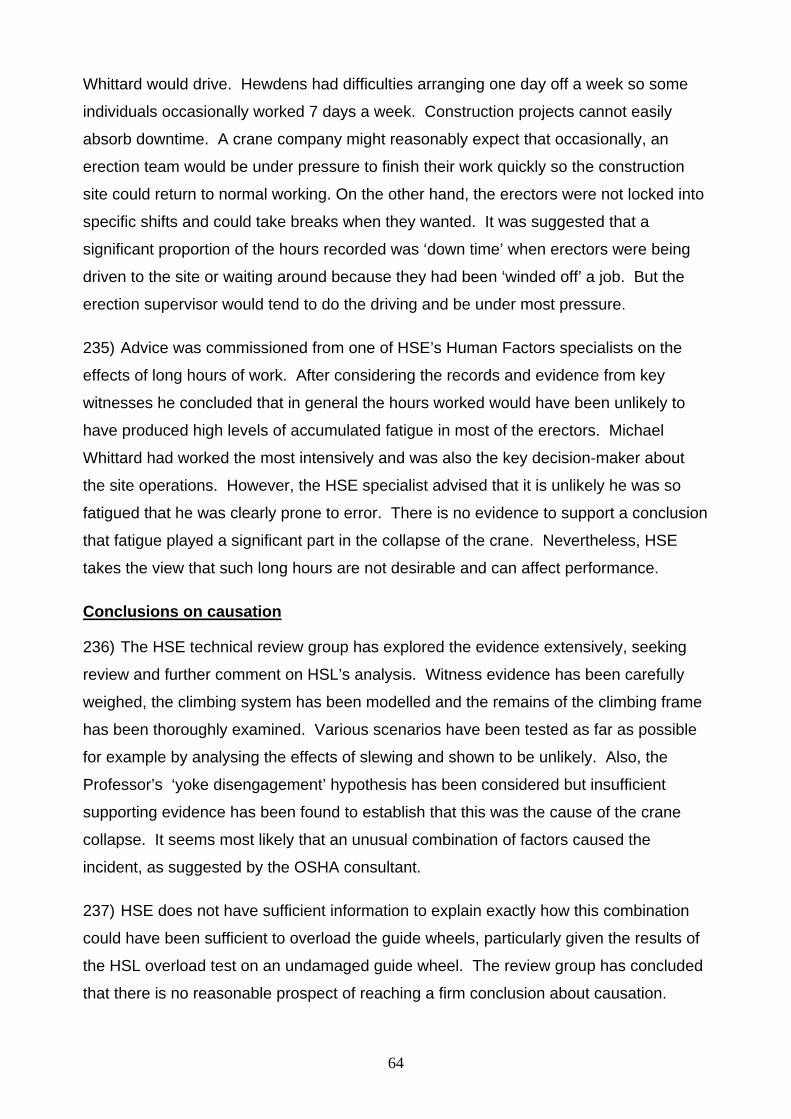
64
Whittard would drive. Hewdens had difficulties arranging one day off a week so some
individuals occasionally worked 7 days a week. Construction projects cannot easily
absorb downtime. A crane company might reasonably expect that occasionally, an
erection team would be under pressure to finish their work quickly so the construction
site could return to normal working. On the other hand, the erectors were not locked into
specific shifts and could take breaks when they wanted. It was suggested that a
significant proportion of the hours recorded was ‘down time’ when erectors were being
driven to the site or waiting around because they had been ‘winded off’ a job. But the
erection supervisor would tend to do the driving and be under most pressure.
235) Advice was commissioned from one of HSE’s Human Factors specialists on the
effects of long hours of work. After considering the records and evidence from key
witnesses he concluded that in general the hours worked would have been unlikely to
have produced high levels of accumulated fatigue in most of the erectors. Michael
Whittard had worked the most intensively and was also the key decision-maker about
the site operations. However, the HSE specialist advised that it is unlikely he was so
fatigued that he was clearly prone to error. There is no evidence to support a conclusion
that fatigue played a significant part in the collapse of the crane. Nevertheless, HSE
takes the view that such long hours are not desirable and can affect performance.
Conclusions on causation
236) The HSE technical review group has explored the evidence extensively, seeking
review and further comment on HSL’s analysis. Witness evidence has been carefully
weighed, the climbing system has been modelled and the remains of the climbing frame
has been thoroughly examined. Various scenarios have been tested as far as possible
for example by analysing the effects of slewing and shown to be unlikely. Also, the
Professor’s ‘yoke disengagement’ hypothesis has been considered but insufficient
supporting evidence has been found to establish that this was the cause of the crane
collapse. It seems most likely that an unusual combination of factors caused the
incident, as suggested by the OSHA consultant.
237) HSE does not have sufficient information to explain exactly how this combination
could have been sufficient to overload the guide wheels, particularly given the results of
the HSL overload test on an undamaged guide wheel. The review group has concluded
that there is no reasonable prospect of reaching a firm conclusion about causation.

65
Therefore, HSE believes it has exhaustively pursued all reasonable lines of enquiry.
However, the investigation has revealed several important factors that can lead to risk in
climbing systems. HSE has taken steps to ensure that these are taken into account by
designers, manufacturers and users in future.
Conclusions on enforcement action
238) HSE undertook a detailed review of all the evidence and sought the advice of
Counsel. Careful consideration has been given to enforcement action in the line with the
Code for Crown Prosecutors and the Health and Safety Commission’s Enforcement
Policy Statement. HSE has decided not to institute legal proceedings in relation to the
incident because:
• as regards any criminal charges directly concerned with the collapse and the three
deaths HSE has concluded that there is insufficient evidence to provide a realistic
prospect of conviction and
• in respect of more 'technical' breaches of health and safety legislation HSE has
concluded that it is not in the public interest to proceed with criminal charges that are
not linked to the collapse of the crane and the three deaths.
Action after the incident 239) Climbing of tower cranes in Great Britain was an uncommon event even at in 2000
– HSE estimates twice a month at its height. Since the incident, the New York twin
towers tragedy and the decline of commercial office building in east London climbing is
comparatively rare in UK – perhaps once every few months.
240) After the incident, HSE served an Improvement Notice on Hewden Tower Cranes
requiring them to arrange for thorough examinations of all their remaining climbing
frames. A press notice was issued as soundings with the industry suggested that it was
fairly common not to have climbing frames thoroughly examined, in those few
companies who used them. Climbing work on DS2 stopped for about six months.

66
241) After the remaining climbing frames had been examined, HSE met with Hewdens
and representatives of the manufacturer. It was agreed that in view of the terrible events
at Canada Square and uncertainty about causation:
• the manufacturer would organise a special training course on climbing for the
erection teams and until then the manufacturer’s own erection team would carry out
any climbing at the site
• steps would be taken to ensure that the correct electrical plugs were used on the
electrical supply cable to hydraulic unit to prevent the possibility of powered slewing
during climbing
• an indicative balancing radius would be specified if balance weights were not to be
used and the erectors would keep within a maximum variance of two metres from the
indicated radius when balancing the crane in practice
• anemometers would be provided on the replacement for TC3
• Hewdens managers would be present when climbing operations restarted
• Hewdens would revise and extend their risk assessment and method statement
242) Discussions have continued with the successor company about continuing
improvements. HSE has identified a number of actions that crane designers,
manufacturers, suppliers and users could take to minimise the risk of future incidents.
Careful consideration of the factors mentioned in this report may help to secure further
improvements to the Wolff system for climbing; many of these factors will also be
relevant to other designs of climbing frame.
243) In February 2003, HSE published a discussion paper setting out the risks assessed
with the use of external climbing frames. The feedback to this paper was shared with
the chairman and members of the British Standards Committee on cranes ( MHE/3/11).
These points have been taken into account in the preparation of a revision to BS 7121:
Part 5 for users and a proposal for a European standard for manufacturers.
244) HSE took the view that the Machinery Directive (Council Directive 89/392/EEC as
amended by Directives 91/368/EEC, 93/44/EEC and 93/68/eec) applies to the supply of
tower crane climbing gear. The matter was taken to the Article 6.2 committee (as was)
established to consider matters relating to the ‘Machinery Directive’. The committee
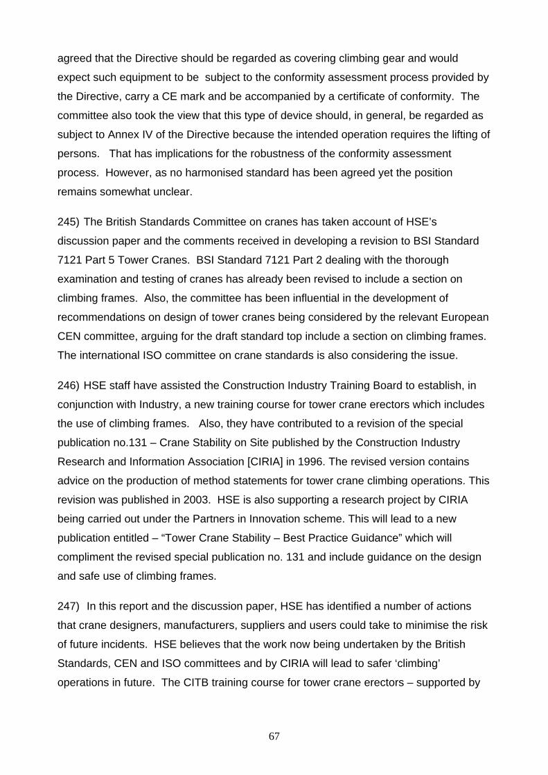
67
agreed that the Directive should be regarded as covering climbing gear and would
expect such equipment to be subject to the conformity assessment process provided by
the Directive, carry a CE mark and be accompanied by a certificate of conformity. The
committee also took the view that this type of device should, in general, be regarded as
subject to Annex IV of the Directive because the intended operation requires the lifting of
persons. That has implications for the robustness of the conformity assessment
process. However, as no harmonised standard has been agreed yet the position
remains somewhat unclear.
245) The British Standards Committee on cranes has taken account of HSE’s
discussion paper and the comments received in developing a revision to BSI Standard
7121 Part 5 Tower Cranes. BSI Standard 7121 Part 2 dealing with the thorough
examination and testing of cranes has already been revised to include a section on
climbing frames. Also, the committee has been influential in the development of
recommendations on design of tower cranes being considered by the relevant European
CEN committee, arguing for the draft standard top include a section on climbing frames.
The international ISO committee on crane standards is also considering the issue.
246) HSE staff have assisted the Construction Industry Training Board to establish, in
conjunction with Industry, a new training course for tower crane erectors which includes
the use of climbing frames. Also, they have contributed to a revision of the special
publication no.131 – Crane Stability on Site published by the Construction Industry
Research and Information Association [CIRIA] in 1996. The revised version contains
advice on the production of method statements for tower crane climbing operations. This
revision was published in 2003. HSE is also supporting a research project by CIRIA
being carried out under the Partners in Innovation scheme. This will lead to a new
publication entitled – “Tower Crane Stability – Best Practice Guidance” which will
compliment the revised special publication no. 131 and include guidance on the design
and safe use of climbing frames.
247) In this report and the discussion paper, HSE has identified a number of actions
that crane designers, manufacturers, suppliers and users could take to minimise the risk
of future incidents. HSE believes that the work now being undertaken by the British
Standards, CEN and ISO committees and by CIRIA will lead to safer ‘climbing’
operations in future. The CITB training course for tower crane erectors – supported by

68
manufacturers’ product-specific training - should also make a significant contribution to
the competence of erectors. HSE would urge crane operating companies to ensure that
they have robust management arrangements for crane erection that extend to infrequent
crane climbing operations. For crane climbing in particular, paragraph 218 above
indicates some of the key issues that require close management attention.
-
June 2006

69
Figures
Figure 1 Typical luffing jib tower cranes on DS1/DS2 after incident Figure 2 Top of TV20.4 mast section showing catch hooks Figure 3 Schematic explanation of external climbing frame equipment Figure 4 Guide Wheel arrangement Figure 5 Demonstration of climb at Castleford – prior to separation of
head Figure 6 Demonstration of climb at Castleford – top part of piston rod
stroke Figure 7 Demonstration of climb at Castleford – moving new mast
section into climbing frame Figure 8 Arrangement of lift cylinder and yoke Figure 9 General area of wreckage showing boundary DS1/DS2 sites Figure 10 Plan of area around DS2 showing wreckage Figure 11 View of Wreckage Figure 12 Close up view of wreckage Figure 13 Sketch of two halves of climbing frame Figure 14 Slewing motor recovered from wreckage Figure 15 Top two mast sections of TC3 after recovery showing the
pattern of damage Figure 16 Drawing of top mast section illustrating the reason for the
pattern of damage Figure 17 Guide Wheel being offered to gouge marks on SE leg Figure 18 Catch hooks on second mast section Figure 19 West side of Yoke showing damage Figure 20 Distorted piston rod Figure 21 North east wheel housing being positioned on base plate

70

71
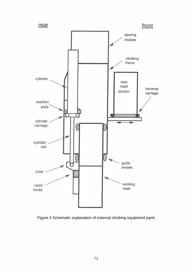
72
Figure 3 Schematic explanation of external climbing equipment parts
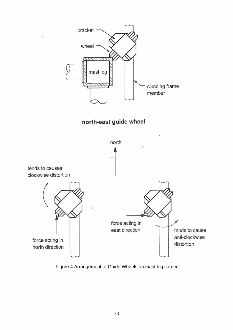
73
Figure 4 Arrangement of Guide Wheels on mast leg corner

74
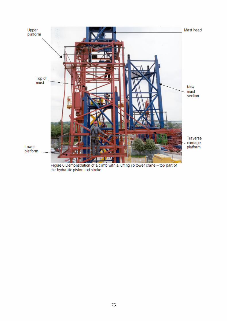
75

76

77
Figure 8 Arrangement of lift cylinder
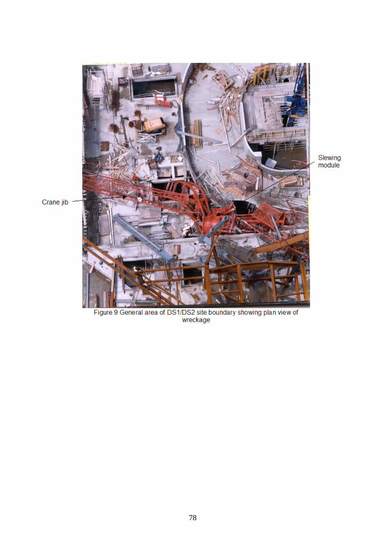
78

79

80

81

82

83

84
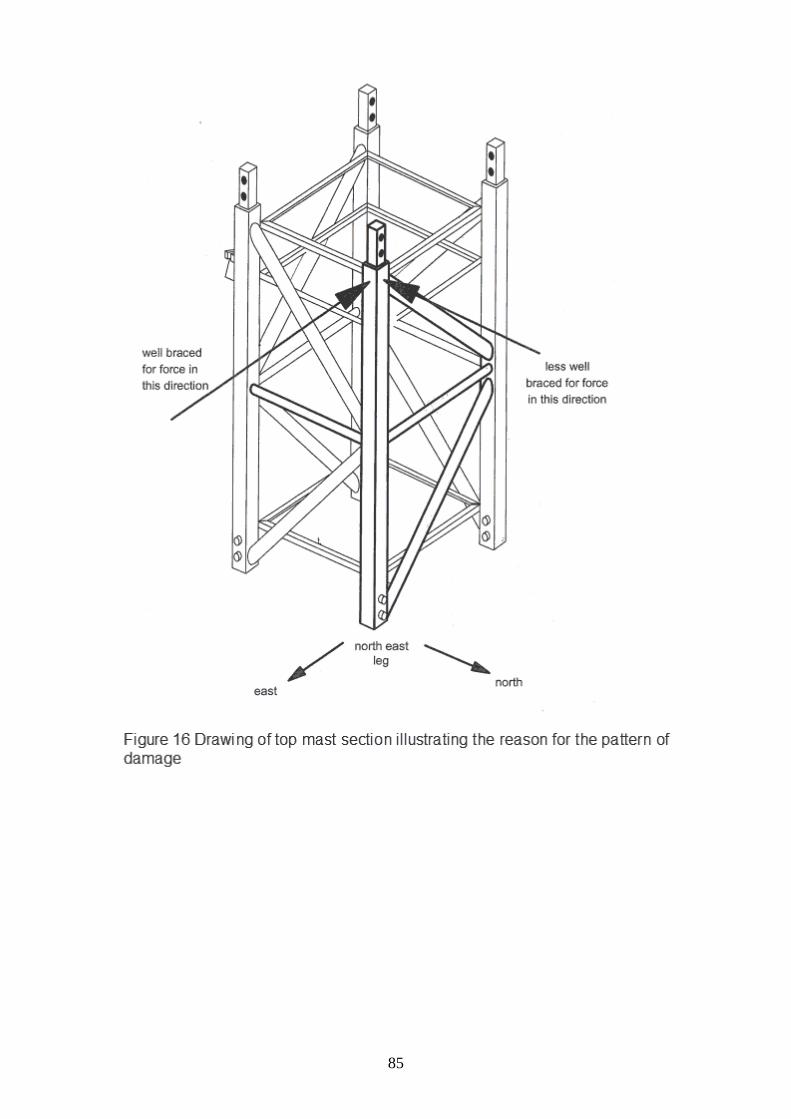
85
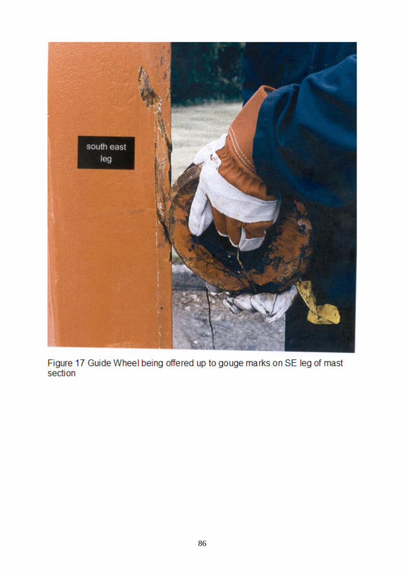
86

87
Figure 18 Photographs of catch hooks on second mast section
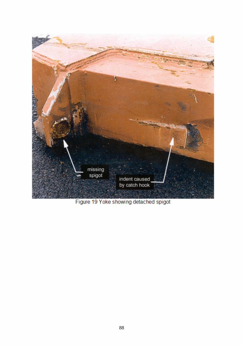
88

89

90