investigation of strength of bolted joint by using fea (dr.j.j.magdum college of engineering,...
TRANSCRIPT

International Research Journal of Engineering and Technology (IRJET) e-ISSN: 2395 -0056
Volume: 03 Issue: 06 | June-2016 www.irjet.net p-ISSN: 2395-0072
© 2016, IRJET | Impact Factor value: 4.45 | ISO 9001:2008 Certified Journal | Page 1345
Investigation of Strength of Bolted Joint by Using FEA
Mr.R.M.Deshmane1, Mr.A.M.Naniwadekar2 1P.G.Student (Dr.J.J.Magdum College of Engineering, Jaysingpur, India)
2Asst.Professor (Dr.J.J.Magdum College of Engineering, Jaysingpur, India)
-----------------------------------------------------------------***--------------------------------------------------------------
Abstract: It is important to predict the behavior of bolted joints. Bolted joints are most commonly used components in machines and structures. Because of stress concentration, bolted joint must be properly designed so that the desired performance from the overall structure is obtained. The research is presented with variants of different array patterns proposed for the shear strength investigation of bolted joint to be used in the industry. 3D models of a bolted joint having different array pattern has been developed by using modeling software Catia and FEM. FEA tools and techniques are being proposed for investing the effectiveness of the bolted joint. Keywords: FEA, Stress analysis, Bolted joint.
1. INTRODUCTION
Threaded joints are used to hold two or machine parts together. These parts can be dismantled, if required, without damage to machine parts or fastening. Therefore, threaded joints are detachable joints. Accordingly, failures typically occurred at joint and interfaces, rather than within the bulk of the system. Hence it is important to design the joint properly so that the desired performance from the overall structure is obtained. To provide a simple, safe and economical joint design, it is essential to configure the joint with respect to the geometry and the constituent materials. While this type of joint is being proposed, the parameters to be considered for the design of the fasteners could be:
1) Type of threaded fastener 2) Size of the fastener 3) Number of fasteners 4) Location for clamping
The parts joined together by threaded joints can be detached as and when required. This required is essential in certain applications for the purpose of inspection, repair or replacement. But different sizes and number of fasteners creates obstacle for efficient assembly. It increases time during maintenance or replacement. The strength of the structural members compromised if the location of the fasteners is not optimized. This paper presented the simulation of stress analysis in a bolted joint. A 3D model of a bolted joint has been created by using modeling software Catia. FEM simulation was carried out by using commercial software ANSYS. In this, stress analysis has been carried out by varying geometrical parameters of bolted joint for optimization.
1.1 FINITE ELEMENT ANALYSIS
Finite element analysis (FEA), is a computational technique used to obtain approximate solutions of engineering problems i.e; to predict the response of structures and materials. Due to the complexity of the structures are usually calculated by numerical methods such as the finite element method. The study will focus on modifying few of above stated parameters to suggest improvements in existing method of fastening. Testing of modified design will be done by using FEM software for stress distribution. FE analysis is widely used to validate the complex designs. The modeling and analysis will be done using Finite Element Analysis software.
Steps for FEA: FEA is mainly divided into three following stages: • Preprocessing
o Creating the model. O Defining the element type o Defining material properties o Meshing o Applying loads o Applying boundary conditions
• Solution: Assembly of equations and obtaining solution • Post processing: Review of results such as deformation plot, stress plot, etc Stages of analysis
A. 3D Modelling in CATIA: The three dimensional models of bolted joint of
circular array pattern and rectangular array pattern with eight number of bolts is prepared in CATIA V5 R16 environment. Model of each geometry in three dimensional views helps to visualize properly and to clear idea about model quickly.
Fig. 1: 3D Model of Circular Array Pattern

International Research Journal of Engineering and Technology (IRJET) e-ISSN: 2395 -0056
Volume: 03 Issue: 06 | June-2016 www.irjet.net p-ISSN: 2395-0072
© 2016, IRJET | Impact Factor value: 4.45 | ISO 9001:2008 Certified Journal | Page 1346
Fig. 2: 3D Model of Rectangular Array Pattern
B. Meshing of geometry using FEA software (ANSYS): FEM analysis is widely used tool in design, the objective of which is to find the stresses in weaker element of product. So the FEM analysis is carried out by using standard commercial software ANSYS. Fine meshing gives an accurate stress distribution in a reasonable analysis time. The finer mesh gives optimal solution is in areas of high stress, i.e; in the contact zones of the joint, then in the remaining areas. In order to simplify the model, hexagonal bolt head and nuts are created as circular and washers are not modeled. Bolts holes are assumed to be equal with bolt size. The elements used in plate assembly model are first order Hexa and Penta elements. Finite element models for stress analysis are consisted of 48794 elements and 274244 nodes each for both circular and rectangular array configuration as shown in Fig. 3 and 4 respectively. Bolt joint model has been meshed by first order Hexa and Penta elements. Element type used is SOLID 185.
Fig. 3: Meshing of Circular Array Pattern
Fig. 4: Meshing of Rectangular Array Pattern
C. Materials and Method: After meshing (Discretisation) of geometric model, the material is specified for both plate and nut-bolts. Two material models were used in this model, one for the plate elements, and the other for the nut-bolts. The
material for the plate is considered as hot rolled steel (HR) and the yield stress considered for the plate is 340 Mpa The material of bolt used is EN8 grade steel having it’s yield stress 950 Mpa, poisson’s ratio 0.3, modulus of elasticity 205*109Pa.
D. Load Application and Boundary Conditions: The loading condition is specified in ANSYS software. Main focus of this thesis is on the stress analysis of threaded fastener (Bolt) under shear loading. Hence end of plate-A is constrained (fixed) by keeping DOF zero for all nodes at the end surface of plate-A. Then a force of 1000 to 5000 N is applied gradually at the right end face of Plate-B in X-direction which acts as tensile force as shown in fig.5 and fig.6.
Fig. 5: Loading Condition of Circular Array Pattern
Fig. 6: Loading Condition of Rectangular Pattern
1. FEA of M10 Bolt in Circular Array Pattern: Two plates of dimension 500 x 180 x 3 mm are connected together by eight number of M10 x 1.5 x 25 mm bolts in circular array pattern placed over the of PCD of 120mm and overlapping length of plates is 241mm as shown in fig.1. Tensile Load has to be applied at one end of the plate and keeping the opposite plate end fixed. Tensile load of 1000 to 5000N is applied gradually in order to determine the maximum equivalent stress induced in bolts for circular array pattern. 3-D geometrical model is prepared on CATIA-V5 software for plates connected with eight numbers of bolts in circular array pattern which is further exported for finite element stress analysis under certain loading condition in FEA software. After application of load the finite element model is solved in ANSYS for the stress results. As the tensile force of 1000-5000 N is applied in Y-direction, the maximum value of equivalent stress component observed is 74.136 Mpa. This is less than the yield strength of the bolt material. The stress values obtained in finite element

International Research Journal of Engineering and Technology (IRJET) e-ISSN: 2395 -0056
Volume: 03 Issue: 06 | June-2016 www.irjet.net p-ISSN: 2395-0072
© 2016, IRJET | Impact Factor value: 4.45 | ISO 9001:2008 Certified Journal | Page 1347
analysis of M10 circular array pattern is shown in table 1 and the contour plot of displacement plot and stress distribution for component i.e. equivalent stress is shown in fig. 7 & 8 respectively.
Table-1 Stress results for M10- Circular Array
Load (N)
Equi. Stress (Mpa)
Displacement (mm)
1000 21.551 0.24587 2000 43.308 0.49172 3000 65.274 0.73755 4000 87.45 0.98334 5000 109.84 1.2291
Fig. 7: Displacement Plot
Fig. 8: Equivalent Stress Distribution
2. FEA of M10 Bolt in Rectangular Array Pattern: Two plates having dimension 500 x 180 x 3 mm are connected together by eight number of M10 x 1.5 x 25 mm bolts in rectangular array pattern with column offset of 120 mm and row offset of 40 mm and overlapping length of plates 220 mm as shown in fig.2. Model is further analysed for stress analysis under the same loading conditions by following the same procedure which is followed for previous analysis of circular array pattern, keeping the bolt material and applied load same.
After application of load, the finite element model is solved and the maximum value of equivalent stress component observed is 50.031 Mpa. This is substantially less than the yield strength of the bolt material. The stress values obtained in finite element analysis of M10 rectangular array pattern is shown in table-2 and the contour plot of displacement plot and stress distribution for component i.e. equivalent stress is shown in fig.9 & 10 respectively.
Table-2 Stress results for M10- Rectangular Array
Load (N)
Equi. Stress (Mpa)
Displacement (mm)
1000 15.811 0.15311 2000 31.52 0.3062 3000 47.126 0.45928 4000 62.63 0.61233 5000 78.033 0.76537
Fig. 9: Displacement Plot
Fig. 10: Equivalent Stress Distribution
G. Result and Discussion:
From the above results we can see that the maximum value of equivalent stress observed in bolts connected in rectangular array pattern (78.033 Mpa) is less than in circular array pattern (109.84 Mpa). This FEM analysis shows that for connection of two members with threaded fastener, the rectangular array pattern is more effective than connecting same members with circular array pattern by keeping number of bolts same. Along with that we can also see that value of maximum displacement of bolt in circular array pattern bolt is more (1.2291mm) than that of rectangular array pattern (0.765mm) as shown in fig. 7 and fig. 9 respectively.
H. Concluding Remarks
In both pattern the maximum stress induced in bolts is within the limit. Means stresses induced in the bolts for both array patterns are less than the yield strength of bolt material which is 950 Mpa. So, here is a scope to use the small diameter bolts to connect the same plates. Hence for the same material and dimensions of plates M8 x 1.25 x 25 mm size bolts are used to connect the two plates in both circular and rectangular

International Research Journal of Engineering and Technology (IRJET) e-ISSN: 2395 -0056
Volume: 03 Issue: 06 | June-2016 www.irjet.net p-ISSN: 2395-0072
© 2016, IRJET | Impact Factor value: 4.45 | ISO 9001:2008 Certified Journal | Page 1348
array pattern and the model is analysed for stress analysis under the same loading conditions by following the same procedure which is followed for previous analysis of M10 bolt, keeping the bolt material and applied load same.
3. FEA of M8 bolts in Circular Array Pattern: Two plates having dimension 500 x 180 x 3 mm are connected together with M8 x 1.25 x 25 mm bolt keeping number of bolts eight in circular array fashion with of PCD as 120mm and overlapping length of 241 mm as shown in fig-1. The maximum stresses are observed in bolt at shank region just beneath the bolt head. The maximum value of stress component i.e; equivalent stress observed is 82.377 Mpa. This is again less than the yield strength of the bolt material. The stress values obtained in finite element analysis of M8 circular array pattern is shown in Table-3 and contour plot of the displacement distribution & stress distribution for stress component i.e. equivalent stress is shown in fig. 11 & 12 respectively. Table-3 Stress results for M8 – Circular Array Pattern
Load (N)
Equi. Stress (Mpa)
Displacement (mm)
1000 22.287 0.25164 2000 44.784 0.50325 3000 67.493 0.75483 4000 90.417 1.0064 5000 113.56 1.2579
Fig. 11: Displacement Plot
Fig. 12: Equivalent Stress Distribution
4. FEA of M8 bolts in Rectangular Array Pattern: Two plates having dimension 500 x 180 x 3 mm are connected together by eight number of M8 x 1.25 x 25 mm bolts in rectangular array fashion with column offset of 120 mm and row offset of 40 mm and overlapping length of plates 220 mm as shown in fig-2. Tensile Load has to be applied at one end of the plate and keeping the opposite plate end fixed. Tensile load of 1000-5000 N has to apply gradually in order to determine the shear stress induced in bolts for rectangular array pattern.
Table-4 Stress results for M8-Rectangular Array
Load (N)
Equi. Stress (Mpa)
Displacement (mm)
1000 20.153 0.1538 2000 40.194 0.30759 3000 60.124 0.46136 4000 79.943 0.61511 5000 99.653 0.76884
Fig. 13: Displacement Plot
Fig. 14: Equivalent Stress Distribution
From the above results we can see that the value
of maximum equivalent stress observed in bolts connected in rectangular array pattern is 99.653 Mpa and in circular array pattern is 113.56 Mpa. This FEM analysis shows that for connection of two members with threaded fastener, the rectangular array pattern is more effective than connecting same members with circular array pattern by keeping number of bolts same. Along with that we can also see that value of maximum displacement of bolt in circular array pattern bolt is more (1.2579mm) than that of rectangular array pattern (0.768mm) as shown in fig.11 and fig.13
International Research Journal of Engineering and Technology (IRJET) e-ISSN: 2395 -0056
Volume: 03 Issue: 06 | June-2016 www.irjet.net p-ISSN: 2395-0072
© 2016, IRJET | Impact Factor value: 4.45 | ISO 9001:2008 Certified Journal | Page 1349
respectively. Results obtained from analytical analysis are as follows:
Table 5 Results for M10 Bolts:
Stress Component → Equivalent
stress (Mpa)
Displacement (mm)
M10- Circular Array 109.84 1.2291
M10- Rectangular Array
78.033 0.76537
.
Fig. 15 Comparative Results for M10 Circular and M10 Rectangular Pattern Variants
Table 6 Results for M8 Bolts:
Stress Component → Equivalent
stress (MPa) Displacemen
t (mm)
M8- Circular Array 113.56 1.2579
M8- Rectangular Array 99.653 0.76884
Fig. 16 Comparative Results for M8 Circular and M8 Rectangular Pattern Variants
Table 7 Results obtained from analytical analysis
Variant Stress (MPa)
Displacement(mm)
M10- Circular Array 109.84 1.2291
M10- Rectangular Array
78.033 0.76537
M8- Circular Array 113.56 1.2579
M8- Rectangular Array 99.653 0.76884
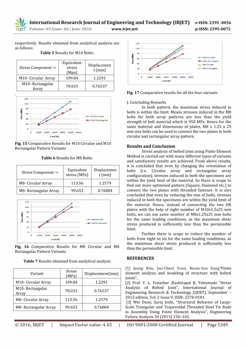
Fig. 17 Comparative results for all the four variants J. Concluding Remarks
In both pattern, the maximum stress induced in bolts is within the limit. Means stresses induced in the M8 bolts for both array patterns are less than the yield strength of bolt material which is 950 MPa. Hence for the same material and dimensions of plates, M8 x 1.25 x 25 mm size bolts can be used to connect the two plates in both circular and rectangular array pattern.
Results and Conclusion Stress analysis of bolted joint using Finite Element
Method is carried out with many different types of variants and satisfactory results are achieved. From above results, it is concluded that even by changing the orientation of bolts (i.e. Circular array and rectangular array configuration), stresses induced in both the specimens are within the yield limit of the material. So there is scope to find out more optimized pattern (Square, Diamond etc.) to connect the two plates with threaded fastener. It is also concluded that even by reducing the size of bolts, stresses induced in both the specimens are within the yield limit of the material. Hence, instead of connecting the two HR plates with the help of eight number of M10x1.5x25 mm bolts, we can use same number of M8x1.25x25 mm bolts for the same loading conditions, as the maximum shear stress produced is sufficiently less than the permissible limit.
Further there is scope to reduce the number of bolts from eight to six for the same loading conditions, as the maximum shear stress produced is sufficiently less than the permissible limit.
REFERENCES
[1] Jeong Kim, Joo-Cheol Yoon, Beom-Soo Kang“Finite element analysis and modeling of structure with bolted joints”, [2] Prof. Y. L. Yenarkar ,Rashtrapal B. Teltumade “Stress Analysis of Bolted Joint”, International Journal of Engineering Research & Technology (IJERT), September – 2013 edition, Vol. 2 Issue 9, ISSN: 2278-0181. [3] Wei Duan, Suraj Joshi, “Structural Behavior of Large-Scale Triangular and Trapezoidal Threaded Steel Tie Rods in Assembly Using Finite Element Analysis”, Engineering Failure Analysis 34 (2013) 150–165.

International Research Journal of Engineering and Technology (IRJET) e-ISSN: 2395 -0056
Volume: 03 Issue: 06 | June-2016 www.irjet.net p-ISSN: 2395-0072
© 2016, IRJET | Impact Factor value: 4.45 | ISO 9001:2008 Certified Journal | Page 1350
[4] H. Fransplass, M. Langseth, O.S. Hopperstad, “Numerical study of the tensile behaviour of threaded steel fasteners at elevated rates of strain”, International Journal of Impact Engineering 54 (2013) 19-30. [5] Abhay K. Jha, M. Swathi Kiranmayee, Sushant K. Manwatkar “Failure analysis of maraging steel fasteners used in nozzle assembly of solid propulsion system”, Engineering Failure Analysis 27 (2013) 308–313. [6] Tianliang Qin “Fastener effects on mechanical behaviors of double-lap composite joints”, Composite Structures 100 (2013) 413–423. [7] Mohamed Tahar Nasraouia , Jamel Chakharib , Boubaker Khalfi , Mustapha Nasria, “Numerical and Experimental Study of Shear Loaded Bolted Joint”, International Journal of Current Engineering and Technology ISSN 2277 - 4106 © 2013 INPRESSCO.