investigation of boiling front during vacuum drying …
TRANSCRIPT
INVESTIGATION OF BOILING FRONT DURING VACUUM DRYING OF WOOD
Zhangjing Chen? Research Associate
and
Fred M. Lamb? Professor
Department of Wood Science and Forest Products Virginia Polytechnic lnstitute and State University
Blacksburg, VA 24061 -0503
(Received November 2000)
ABSTRACT
The objective of this research was to theoretically and experimentally investigate the boiling phe- nomenon and the existence of a boiling front inside wood during continuous and cyclic vacuum drying. The vacuum drying model was theoretically developed based on an energy balance. The experimental results supported the hypothesis that there is a boiling front during vacuum drying. From the boiling front to the surface of the wood, the boiling temperature is lower than the wood temperature, so water in this region boils. From the boiling front to the center of wood, there is no boiling because the pressure inside the wood is higher than the saturation vapor pressure. The boiling front retreats from the surface to the center of the wood as drying proceeds. The speed of retreat depends on the heat supply and properties of the wood, such as permeability and conductivity.
Kr~vvord.~: Vacuum drying, drying model
INTRODUCTION
When the local atmospheric pressure is low- er than the saturated vapor pressure of water, water boils. When wood is placed in a vacu- um, most investigations support the concept that water boils in the wood during drying as the boiling temperature is lowered. In radio- frequency vacuum drying, the temperature of wood reaches the boiling temperature in a very short time (Avramidis et al. 1994).
However, Neumann et al. (1992) simulta- neously measured the temperatures and the pressures at different depths of beech boards during convective vacuum drying in super- heated steam at 150 mm Hg. They found that pressures at different depths were always higher than the saturation pressures corre- sponding to the local temperatures. They con- cluded that water is not boiling in the wood
-1- Member of SWST.
and that the faster drying in vacuum drying may not be attributed to the boiling phenom- enon as most researchers supposed.
The boiling front concept has been pro- posed by Chen and Lamb (1995). They sug- gested that not only is water boiling inside the wood, but also there is a boiling front. From the boiling front to the surface of wood, boil- ing temperature is lower than wood tempera- ture and moisture in this region boils. From the boiling front to the center of wood, there is no boiling because the pressure inside wood is higher than the saturation vapor pressure. The boiling front retreats from the surface to the center of the wood as the drying proceeds. The retreating speed depends on the heat sulp- ply and properties of wood, such as perme- ability and conductivity. There is still a debate as to whether or not water inside the wood boils during vacuum drying. The objective of this research was to investigate the boiling
ll/l,od urrd f,h<,r S r <en< r . 33(4). 2001. p p 639-647 r 2001 hy t h i Soc~ety of Wood Sc~rlice and 'rruhnt,logy
640 WOOD AND FIBER SCIENCE, OCTOBER 2001, V. 33(4)
phenomenon and the existence of a boiling front inside the wood during continuous and cyclic vacuum drying.
THEORETICAL DEVELOPMENT
The objective of the first part of this study was to develop the heat and mass transfer equations by using present vacuum drying concepts, together with certain assumptions. Equations are developed to evaluate tempera- ture distribution, pressure distribution, and the boiling front.
The mechanism of vacuum drying depends on the pressure inside the vacuum dryer and the physical properties of the wood. In the case of cyclic vacuum drying, the lumber is heated to a given temperature, and then a vac- uum is pulled. For any fixed pressure, there exists a temperature at which water boils. Boiling occurs in the wood because the wood temperature is higher than the saturation tem- perature inside the vacuum dryer. At the be- ginning, boiling occurs on the surface, then the boiling front retreats inward. The moving boiling front divides the system into two re- gions, namely, the boiling region and non- boiling region. In the boiling region, moisture occurs in the form of mixed vapor and liquid. In the non-boiling region, the moisture is in liquid form; however, the small amount of wa- ter vapor contained in the trapped air in the lumen is neglected (Bramhall 1979).
For the purpose of formulating the cyclic vacuum drying model, the following assump- tions are made:
1 ) Only two-dimensional (longitudinal and transverse) heat and mass transfer is consid- ered, since the difference between radial and tangential permeability values is very small by comparison with the difference between radial and longitudinal permeability values (Siau 1984), and lumber width is larger than its thickness.
2) At beginning of drying, lumber is ini- tially at a uniform temperature, pressure, and moisture content (MC).
3) The rate of evaporation from the lumber
surface is very high. The lumber surface reaches equilibrium with the surrounding at- mosphere when evaporation starts (Vergnaud 1982).
4) The heat convection and radiation on the surface of lumber, the thermal expansion, the shrinkage, and Soret effects are all assumed to be small and therefore negligible (Vergnaud 1982).
5 ) The lumber is dried by maintaining the drying chamber at constant vacuum pressure and constant temperature.
6 ) The differential heat of sorption is con- siderably smaller than the heat of water va- porization and is neglected (Vergnaud 1982).
Governing equations
In order to formulate heat and mass transfer equations for vacuum drying, it is necessary to obtain a simultaneous solution of coupled heat and mass transfer equations with a mov- ing boiling from that separates the boiling and non-boiling regions.
In the non-boiling region, heat conduction is described by the Fourier's equation:
where T is temperature, t is time, x is axis that represents longitudinal direction, y is axis that represents radial direction, K, and Kl are the thermal conductivities of wood in the trans- verse and longitudinal directions,
where: c and p are specific heat and density of wood respectively. Similarly, the pressure dis- tribution can be characterized by the equation (Siau 1984):
where P is the pressure, K ~ , and K,, are the gas permeability values of wood in the longitudi- nal and transverse directions.
Chen and Lamb-BOILING FRONT DURING VACUUM DRYING 64 1
where Kg, and Kg, are the specific permeability values of wood in the longitudinal and trans- verse directions, y is gas viscosity.
Term a can be expressed:
where V, is the void fraction or porosity of wood, R is the gas constant, p, is density of gas.
In boiling region, the effect of mass transfer on heat transfer will also be considered. Ac- cording to the first law of thermodynamic for a control volume, the energy equation can be written as follows:
where h is the enthalpy, m is the mass flow rate that includes the capillary flow and water vapor bulk flow, dE/dt is the rate of energy change inside the control volume, Q is con- duction heat transfer. The subscripts e and i represent the flow out and into the control vol- ume, which include the free water and water vapor.
It requires heat to evaporate water. The amount of water evaporated is assumed to be the same as water vapor removed from the control volume. Equation (4) can be written as the following partial equation (Chen 1997):
dT d2T d 2 T d m X u A - = K , X - - + K , X - - -
at ax2 ay2 dtdxdy
- hemc - h,m,
dxdy
where u is the internal energy of water in liq- uid form, h is the evaporation heat and dm is the weight loss in the dt time interval. d d d t is the drying rate.
The thermodynamic relationship between saturated pressure and temperature is given by (Siau 1984):
Po = 8.75 X lo8 X exp ( -- 4g2) (6)
where Po is saturated pressure, mm Hg, R is gas constant, 8.306 JIM01 K, T is Kelvin tern- perature.
When the MC is below fiber saturation point (FSP), the Hailwood-Horobin sorption theory is used to characterize the relationship between the temperature and pressure inside the wood (Siau 1984).
Boundary condition
For cyclic vacuum drying, the boundary condition can be treated as follows. Because of the low atmospheric pressure in the vacuum chamber, the heat convection inside the cham- ber is small and can be neglected. The mass transfer coefficient is very high due to the rap- id water evaporation on the surface of lumber (Jones 199 1). Therefore, the surface pressure is the same as the environmental pressure in the chamber.
Physical properties qf wood, thermodynam,;c relationship
The relationship between thermal conduc- tivity and MC has been developed empirically (Siau 1984). The thermal conductivity for wood in the longitudinal direction can be ex- pressed as:
K I = 4.18 X [SG X (4.8 + 0.09 X MC)
where K~ is thermal conductivity for wood in the longitudinal direction, J/mm°Cs. when moisture content of wood is below 40%.
SG is specific gravity of wood.
K~ = 4.18 X [SG X (4.8 + 0.125 X MC)
when moisture content of wood is above 405%. Thermal conductivity of wood in the tan-
gential direction is related to thermal conduc- tivity in the longitudinal directions by:
K~ = 2.5 X K, (9)
where K, is thermal conductivity for wood in the transverse direction, J/mm°Cs.
642 WOOD AND FIBER SCIENCE, OCTOBER 2001, V. 33(4)
The porosity of wood is given by the em- pirical equation:
V, = I - SG X (0.667 + 0.01 X MC) (10)
where V , is porosity of wood. The relation between the specific heat of
wood and its MC is given (Skaar 1972): where c is the specific heat of wood.
The density of wood is as follows:
p = SG X ( 1 + 0.01 X MC) X p,,
where p, is density of water. The zero enthalpy reference state is chosen
to be 0°C and 1 atmosphere pressure. The en- thalpy of water vapor is then a function of temperature only.
The relation of enthalpy (J/g) with temper- ature T ("C) is (Stanish et al. 1986):
where h is enthalpy of water. The air viscosity (newton/mm2) is:
where q g d is air viscosity. The viscosity of saturated steam qg, (new-
ton/mm2) is:
where qg, is viscosity of saturated steam. If there is free water, the gas phase at any
point is assumed to be saturated at the local temperature. The saturated water vapor den- sity for steam tables over the temperature range T of 27 to 200°C is as follows (Stanish et al. 1986):
TABLE 1. Empirical constants used in the model (Eqs. 1, 2, and 5).
Factor Constant
Specific Gravity of Red Oak 0.56 Specitic Gravity of White Oak 0.60 Initial Temperature ("C) 70 Initial Pressure (mm Hg) 760 Initial MC (70) 7 1 Ambient Pressure (mm Hg) 55 Internal Energy of Water (Jlg) 250.91
where p, is the vapor density, g/mm3, T is tem- perature, "C.
The gas and liquid permeability of wood will vary with MC. The longitudinal gas per- meability of dry red oak is 59 darcy, and the liquid permeability of saturated red oak is 139 darcy (Choong et al. 1974). For white oak, these two values are 0.712 and 0.604 darcy, respectively (Choong et al. 1974). For red oak, the ratio of longitudinal to radial permeability is 4.9 X lo8 according to Eaton and Hale (1993).
For the theoretical calculation, the size of the board is assumed to be 2440 mm long (8 feet) and 50.8 mm thick (2 inches). The width of board is neglected. A quarter of board (1220 by 25.4 mm) will be solved in the com- puter program. The empirical constants that are used in the calculations are listed in Table 1.
Solution of' the governing equations
Patankar ( 199 1) developed a computer pro- gram called CONDUCT that was used to solve second partial equations (Eqs. 1 , 2, and 5). This program is designed for isotropic mate- rials. It was modified to be used for anisotrop- ic material such as wood. The subroutine was written in order to adapt this program to our situation. CONDUCT has been successfully used in solving the equations related to the heat transfer and viscous incompressible flows (Sparrow et al. 1978; Karki and Patankar 1988). The finite-difference form of the spatial derivatives developed in CONDUCT has also

Chen und Lamb-BOILING FRONT DURING VACUUM DRYING 643
0 200 400 600 800 1000 1200 1400
Distance from EndOrain Surface (mm)
-C White Oak+ Red Oak
FIG. 1. Locations of calculated boiling front for red and white oaks from vacuum drying model.
been used in wood drying modeling (Stanish et al. 1986).
Result of modeling
The results of the calculation provide the pressure and the temperature distribution data. From these, boiling front information can be obtained (Fig. I ) .
When drying starts, pressure decreases in the lumber. The pressure on the surface de- creases first and water on the surface rapidly evaporates (Jones 199 1 ). As drying continues, pressure inside the wood is lowered. When the pressure is equal to or lower than the saturated pressure at the local temperature, water boils. Pressure inside the wood is lowered due to mass loss during drying. At the beginning, the mass loss is mostly air. When the pressure is lower than saturated pressure, water boils. There is little air left in the lumen, and water vapor occupies the large volume of lumen. In the boiling region, the pressure and tempera- ture distributions are related. The pressure is saturated at the local temperature when the MC is above FSP. In the absence of free water, the total pressure is assumed to be at equilib- rium with the local temperature and MC, and the pressure is less than the saturation pres- sure. Generally the temperature gradient is small due to the relatively large thermal con- ductivity. Figure 1 shows the movement of the
boiling front in the longitudinal direction for red oak and white oak, respectively. When the pressure inside the lumber is lower or equal to the saturated pressure, water boils. This hap- pens during vacuum drying. Initially, boiling occurs on the surface. The boiling front then moves toward the center of the wood as dry- ing continues, leaving a boiling region behind. At the beginning of drying (because the teim- perature of the lumber is higher than the sat- uration temperature), moisture on the surface evaporates and transfers out. As moisture flows out of the lumber, the pressure decreases and boiling occurs in the inner layers of the lumber. The boiling front then moves towilrd the center in the longitudinal direction. From the boiling front to the center, the local pres- sure is higher than the saturated pressure at the local temperature; therefore boiling does riot occur. From the equations, the boiling region extends to the whole board very rapidly for a permeable wood like red oak. However l'or less permeable woods (such as white oak), it takes longer. The retreating speed of the boil- ing front strongly depends on the longitudi~ial permeability of wood.
Continuous vacuum drying differs from cy- clic vacuum drying in the way heat is supplied to the wood. The governing equations (Eqs. 1, 2, and 4) are the same for continuous vacuum drying as for cyclic vacuum drying. If heat is supplied to the wood during continuous vac- uum drying by way of conduction or radiation, the boundary conditions are different from those of cyclic vacuum drying. The compu- tational results indicate that a boiling front can still exist in continuous vacuum drying.
EXPERIMENTAL INVESTIGATION
The theoretical considerations suggest that there is a boiling front and it retreats to the center of a board as drying proceeds. The ob- jective of this part of the study was to detect the boiling phenomenon and characterize the movement of the boiling front.
Specimen preparation
Specimens used in the experiments were se- lected from red oak heartwood lumber. The
644 WOOD AND FIBER SCIENCE, OCTOBER 2001, V. 33(4)
TABLE 2. Two locutions in the specimen.^ fi)r measuring pressures and temperatures.
Locations
D r y ~ n g method MC A ( m m ) 8 (mm)
Continuous Drying High Initial MC 25.4 50.8 (38.36%)
Low Initial MC 8 25.4 (8.83%)
Cyclic Drying High Initial MC 8 25.4 (50.92%)
Low Initial MC 8 25.4 (9.89%)
2440-mm-long logs were obtained from the local area. Flat sawn boards with the dimen- sion of 38.1 mm thick and more than 254 mm wide were cut from the logs at the sawmill. The lumber was stored in a cold room to min- imize MC loss before the specimens were cut. When specimens were needed, a 305-mm length was cut from each end of the boards and discarded. The specimens were cut from the remaining material. All specimens were 63.5 (width) X 38.1 (thickness) X 254 (length) mm in size.
Two pairs of 3.175-mm holes were drilled in each specimen. They are designated as lo- cations "1" and "2". In each pair of holes, one hole was used for the pressure probe and other for the temperature probe. The A and B values presented in Table 2 are the distances from locations "1" and "2" to the end grain of the boards.
Glass tubes with an outside diameter of 1.727 mm and an inside diameter of 1.27 mm were inserted into the holes and sealed with epoxy. Rubber tubes with an inside diameter of 1.27 mm and an outside diameter of 3.3 mm were then used to connect the glass tubes to the pressure transducers.
Equipment
The experimental system consisted of a vac- uum oven, vacuum pump, and cooling system. A Napco vacuum oven (model 586 1 ) was used having inside dimensions 460 by 610 by 460 mm. A Busch oil-sealed pump (model RA
0025-A005) was connected to the vacuum oven and is capable of pulling a vacuum to 15 mm Hg. A water-cooled Neslab cooling sys- tem (model cc-70W) was used to provide the low temperature needed for the vapor freezing traps.
During the experiments, temperatures were measured with a resistance temperature device (RTD) having an accuracy of -to. 1°C. The pressures were measured using pressure trans- ducers (model #PX2 13-01 5A5V, Omega Co.) having the accuracy of +-2 mm Hg. Weights were measured by a load cell (model # LC601-5, Omega Co.) with a capacity of 2.27 kg.
Experimental procedure
Both cyclic and continuous vacuum drying were investigated. Experiments were conduct- ed for the high MC (above FSP) and low MC (abut 10%) specimens for both cyclic and con- tinuous vacuum drying. Sixteen experiments (four at each condition) were conducted. One specimen was dried at a time. In cyclic vac- uum drying, a conventional heating oven was used to heat specimens to the required tem- perature, while the vacuum oven was main- tained at the room temperature (20°C). The temperature in the heating oven was set at 60°C. To avoid losing moisture during heating, the specimen was wrapped in plastic film and sealed in plastic bags. When the temperature reached 60°C, the specimen was removed from the heating oven, the plastic film re- moved, and the specimen was inserted into the vacuum oven. The temperature probes were inserted into the holes after heating. The rub- ber tubes were then connected to the glass tubes to measure the pressure. Then the spec- imen was hung on the load cell and vacuum drying started. The end-grain surface temper- atures, ambient temperatures, and tempera- tures at location " 1 " and "2" were measured. Ambient pressure and pressures at location "1" and "2" were measured. The weight, pressure, and temperature readings were re- corded during the drying every thirty seconds
Chen and Lamb-BOILING FRONT DURING VACUUM DRYING 645
0 1 I 0 2 4 6 8 10 12 14 16 18 20 22 24
Time (min)
- Ambient Pressure - End Surface Sahxahon Pressure
- Amb~ent Sahmtion Pressure
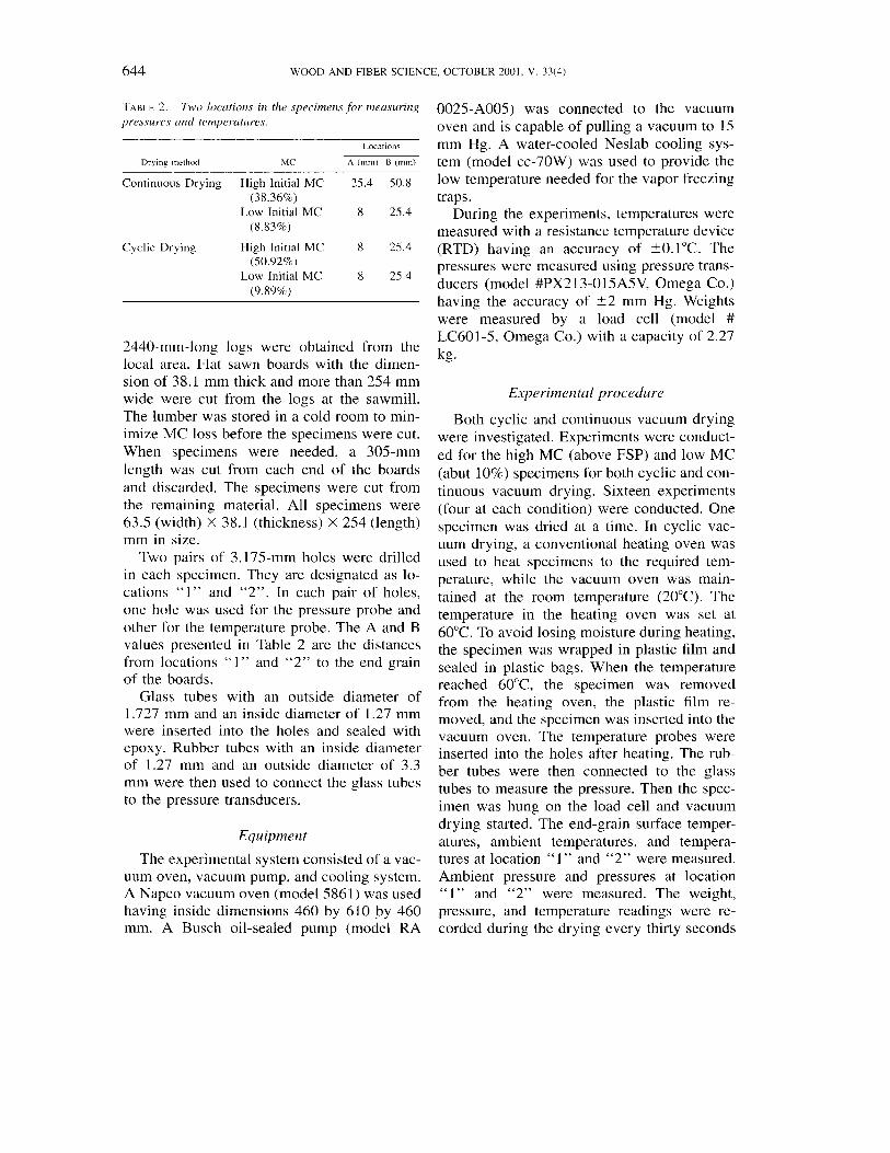
FIG. 2. Pressure and saturation pressure curves of am- bient environment and end-grain surface in continuous vacuum drying of red oak specimen.
l o 0 OI 0 200 400 600 800 1000
Time (mm)
- Pressure at 5.08 cm - Pressure at 2.54 cm
- Saturat~on Pressure at 2.54 cm + Saturation Pressure at 5.08 cm
FIG. 3. Pressure and saturation pressure curves at dif- ferent locations in red oak specimen in continuous vacu- um drying.
for specimens of low initial MC and every mi- a high MC specimen and the cyclic vacuum nute for specimens of high initial MC. Where drying of a low MC specimen. the temperature of the specimen was equal to or lower than the ambient temperature, cyclic drying was stopped.
For continuous vacuum drying, the speci- men was heated in the vacuum oven. After the specimen was hung on the load cell, the heat- ing device was turned on to heat the sample. The temperature was controlled at 60°C. The data were recorded every minute for speci- mens of low initial MC and every five minutes for specimens of high initial MC. When the temperatures in the designated locations were higher than the saturated temperature, drying was stopped.
The experimental results are recorded as temperature and pressure curves versus time. There are three pressures, the ambient pressure and the pressures at locations "1 " and "2". There are four temperatures-the ambient temperature, end-grain surface temperature, and the temperatures at locations "1" and "2". The four saturation pressures corre- sponding to the four local temperatures (am- bient temperature, end-grain surface tempera- ture, and temperatures at locations "1" and "2") were calculated. These pressure curves and saturation pressure curves are presented in Figs. 2 to 5 for continuous vacuum drying of
Data analysis and discussion
The calculated saturation pressures were compared with the measured pressures at the same times and locations. If the calculated sat- uration pressure was higher than the corre- sponding measured pressure, boiling was as- sumed to occur at this location. From Fig. 3, it is clearly seen that there was boiling during vacuum drying and that the boiling front
Time (min)
- Amblent Pressure -.. Amb~ent Saturation Pressure
-- End Surface Saturation Pressure
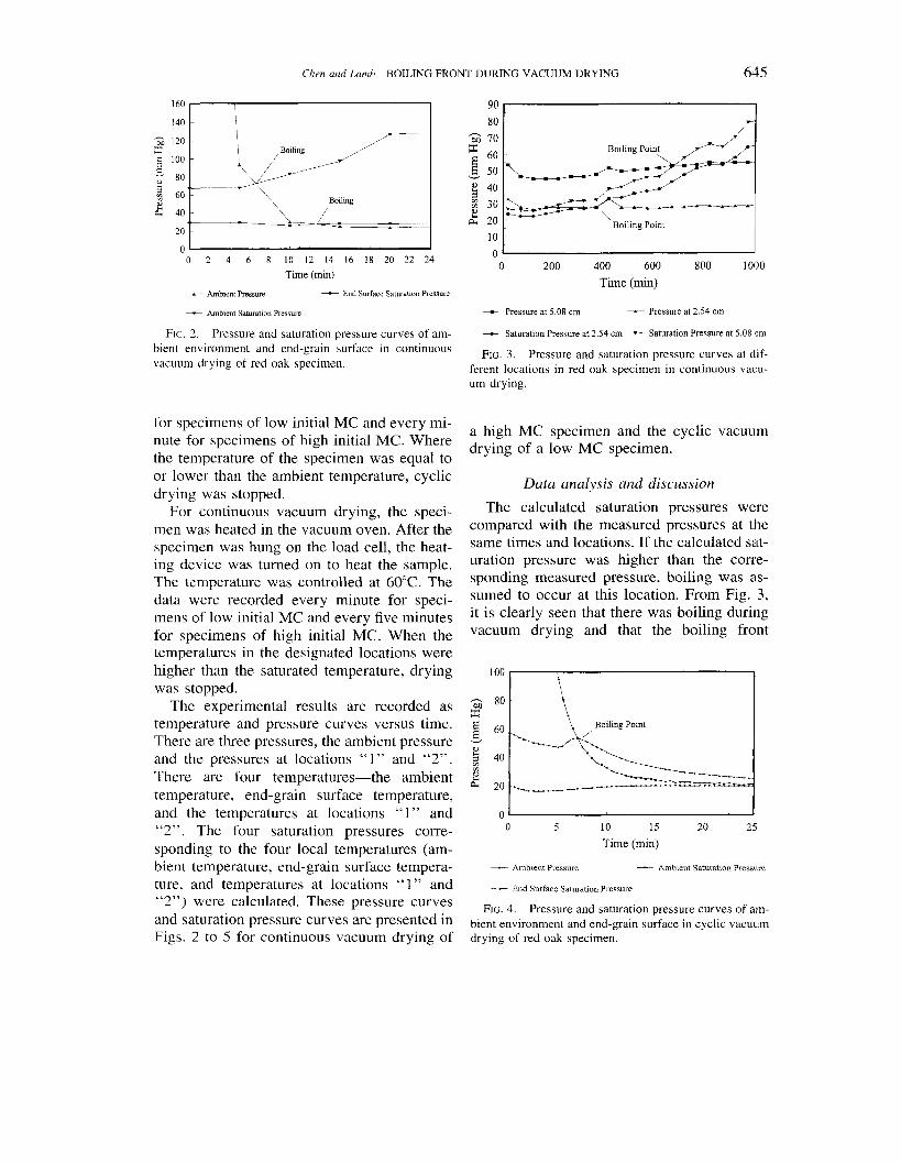
FIG. 4. Pressure and saturation pressure curves of am- bient environment and end-grain surface in cyclic vacuum drying of red oak specimen.
646 WOOD AND FIBER SCIENCE, OCTOBER 2001, V. 3 ~ 4 )
0 1 I 0 1 2 3 4 5 6 7 8 9 1 0 1 1 1 2
Time (min) - Pressure at 25 4 mm t Pressure at 8 mm
+ Sahlrat~on Pressure at 8 mm Saturat~on Pressure at 25 4 mm
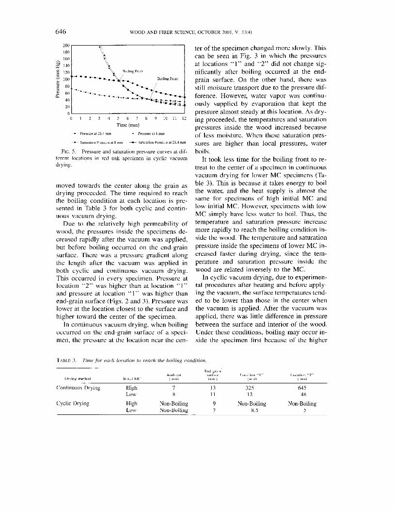
FIG. 5. Pressure and saturation pressure curves at dif- ferent locations in red oak specimen in cyclic vacuum drying.
moved towards the center along the grain as drying proceeded. The time required to reach the boiling condition at each location is pre- sented in Table 3 for both cyclic and contin- uous vacuum drying.
Due to the relatively high permeability of wood, the pressures inside the specimens de- creased rapidly after the vacuum was applied, but before boiling occurred on the end-grain surface. There was a pressure gradient along the length after the vacuum was applied in both cyclic and continuous vacuum drying. This occurred in every specimen. Pressure at location "2" was higher than at location " 1 " and pressure at location " 1" was higher than end-grain surface (Figs. 2 and 3). Pressure was lower at the location closest to the surface and higher toward the center of the specimen.
In continuous vacuum drying, when boiling occurred on the end-grain surface of a speci- men, the pressure at the location near the cen-
TABLE 3. Time fi~r ruch locution r o reach the boiling condition
ter of the specimen changed more slowly. This can be seen in Fig. 3 in which the pressures at locations "1" and "2" did not change sig- nificantly after boiling occurred at the end- grain surface. On the other hand, there was still moisture transport due to the pressure dif- ference. However, water vapor was continu- ously supplied by evaporation that kept the pressure almost steady at this location. As dry- ing proceeded, the temperatures and saturation pressures inside the wood increased because of less moisture. When these saturation pres- sures are higher than local pressures, water boils.
It took less time for the boiling front to re- treat to the center of a specimen in continuous vacuum drying for lower MC specimens (Ta- ble 3). This is because it takes energy to boil the water, and the heat supply is almost the same for specimens of high initial MC and low initial MC. However, specimens with low MC simply have less water to boil. Thus, the temperature and saturation pressure increase more rapidly to reach the boiling condition in- side the wood. The temperature and saturation pressure inside the specimens of lower MC in- creased faster during drying, since the tem- perature and saturation pressure inside the wood are related inversely to the MC.
In cyclic vacuum drying, due to experimen- tal procedures after heating and before apply- ing the vacuum, the surface temperatures tend- ed to be lower than those in the center when the vacuum is applied. After the vacuum was applied, there was little difference in pressure between the surface and interior of the wood. Under these conditions, boiling may occur in- side the specimen first because of the higher
End gram Amhlent surfacc Location "1" Location "2"
I)rylnp method l n ~ t ~ n l M C i r n ~ n ) (mln) (mm) imln)
Continuous Drying High 7 13 325 645 Low 8 11 12 48
Cyclic Drying High Non-Boiling 9 Non-Boiling Non-Boiling Low Non-Boiling 7 8.5 5

('hrrr clnd hmh-BOILING FRONT DURING VACUUM DRYING 6.47
interior temperature. This is the situation that occurred in the low initial MC specimens (Fig. 5 ) . If at the beginning of drying, there had not been a temperature gradient, boiling would have occurred at the end-grain surface first.
For higher initial MC specimens, due to limited heat supply, locations inside the spec- imens did not reach the boiling condition. The boiling condition inside the wood was almost reached, but the local saturation pressure was not sufficient. However, the surface reached the boiling condition (Table 3). This occurred because more water was available to evaporate near the end-grain surface. Thus, boiling may have occurred near the end-grain surface. However, the pressure near the end-grain sur- face could not be measured. Some boiling may have occurred inside the wood not far from the end surface.
CONCLUSIONS
In vacuum drying of wood, water boils in- side the wood. However, boiling does not oc- cur simultaneously throughout the wood. At the beginning, boiling occurs on the surfaces and the boiling front retreats to the center of the wood as drying proceeds. The boiling front retreats to the center more slowly for specimens having high MC than for specimens having low MC. This phenomenon was found in both the theoretical calculations and the ex- perimental results.
REFERENCES
AVRAMII)IS, S., M. LlU, A N D B. J. NEILSON. 1994. Radio- frequencylvacuum drying of softwoods: Drying of thick
western red cedar with constant electrode voltage. For- est Prod. J. 44(1):41-47.
BRAMHALL, G. 1979. Mathematical model for lumber dry- ing. 11. The model. Wood Science 12(1):14-21.
CHEN, Z. 1997. Primary driving force in wood vacuum drying. Ph.D. dissertation, Virginia Tech., Blacksburg, VA. http://scholar.lib.vt.edultheseslavai1able/etd-021'~8- 1855381
, AND E M. LAMB. 1995. The concept of boiling front in vacuum drying. Vacuum Drying of Wood '95. Slovakia. Pp. 1 10-1 16.
CHOONG, E. T., E 0 . TESORO, AND E G. MANWILLER. 19'74. Permeability of twenty-two small diameter hardwoods growing on southern pine sites. Wood Fiber 6(1):91- 101.
EATON, R. A., AND M. D. C. HALE. 1993. Wood: Dec.ay, pests, and protection. Chapman and Hall, New York, NY. 546 pp.
JONES, E E. 1991. Evaporation of water. Lewis Publisi-~er, Chelsea, MI. I88 pp.
KARKI, K. C., AND S. V. PATANKAR. 1988. Calculation pro- cedure for viscous impressible flows in complex ge- ometries. Num. Heat Transfer 14(3):295-3 17.
NEUMANN R., A. MIELKE, AND G. BOHNER. 1992. Com- parison of conventional and convective vacuum drying of beech. Understanding the Wood Drying Process: A Synthesis of Theory and Practice. 3rd IUFRO Interna- tional Wood Drying Conference. Vienna, Austria.
PATANKAR, S. V. 1991. Computation of conduction and duct flow. Heat Transfer Innovative Research Inc., Ma- ple Grove, MN. 354 pp.
SIAU, J. E 1984. Transport process in wood. Springer-Ver- lag, New York, NY. 218 pp.
SKAAR, C. 1972. Water in wood. Syracuse Univ. Press, Syracuse, NY. 2 18 pp.
SPARROW, E.M., S. V. PATANKAR, AND H. SHAHRESTANI. 1978. Laminar heat transfer in a pipe subjected to a circumferentially varying enteral heat transfer coei'ti- cient. Num. Heat Transfer 1 (I): 1 17-127.
STANISH, M. A,, G. S. SCHAJER, AND E KAYIHAN. 1986. A mathematical model of drying for hygroscopic porous media. AIChE J. 32(8): 1301-1 3 11.
VERGNAUD, J. M. 1982. Drying of polymeric and solid materials. Springer-Verlag, New York, NY. 336 pp.