inverter ride through functions - iso new england...ieee 1547 / 1547.1 does not yet consider ride...
TRANSCRIPT

Inverter Ride through Functions
John Berdner Director of Worldwide Standards
Presentation Outline
| © 2013 Enphase Energy, Inc. | Confidential 2
• Acknowledgements • Background - Ride Through versus Trip Settings
• Objectives • Operating Regions • Modes of Operation • Return to Service Behavior
• CA Rule 21 Recommended Settings • Regulatory Issues • Real and Reactive Power Functions

Acknowledgments
| © 2013 Enphase Energy, Inc. | Confidential 3
• This presentation is intended to give an overview of issues associated with inverter based ride through functions.
• The recommendations provided herein are based on the work done to date by the California Smart Inverter Working Group, and the UL 1741 / IEEE 1547 Working Groups for ride through
• These recommendations represent an evolving consensus of the active utility and inverter industry members of the Smart Inverter Working Group and those participating in the 1741 / IEEE 1547 revision process.

Background - Ride Through vs Trip Settings
| © 2013 Enphase Energy, Inc. | Confidential 4
• Historically US regulations have been written around must disconnect requirements not around must remain connected requirements.
• Extended trip settings with large voltage and frequency windows DO NOT ensure that DER will stay online during abnormal frequency excursions.
• Additional specification of ride through needed to insure that DER remains online during these excursions.
• The issues are complex and the desired behavior varies depending on the direction, magnitude and duration of the excursions as well as utility specific operational considerations, e.g. coordination with load shedding and voltage regulation schemes.
Why is Ride Through Needed ?
| © 2013 Enphase Energy, Inc. | Confidential 5
• Fundamentally, ride through is needed to avoid cascade failure of the utility grid during severe under frequency events, and to a lesser degree, severe under voltage events.
• Limit loss of generation to “an acceptable level” • During severe under frequency events DER should
remain online until local load shedding schemes have activated.
• Local Load shedding schemes will shed load AND generation simultaneously thereby minimizing the net loss of generation during an event.
• If DER is lost ahead of load, grid instability may quickly worsen and possibly lead to cascade failure.
Abnormal Excursions
| © 2013 Enphase Energy, Inc. | Confidential 6
• Abnormal excursions can be divided into four basic types.
• Under frequency – below 59 Hz • Over frequency – above 61.5 Hz • Under voltage – below ANSI Range B. < 88% PU • Over voltage – above ANSI Range B, >110% PU
• During under frequency events it is essential for the DER assets to remain connected primarily to support the bulk system. • Support of distribution system is important but secondary
• In contrast during over voltage and over frequency events the DER should self regulate and attempt to reduce the Voltage or frequency
Objectives – Low Frequency Ride Through
| © 2013 Enphase Energy, Inc. | Confidential 7
• Low frequency ride through (LFRT): • Reduce chances of cascade failures of bulk system by
minimizing sudden loss of DER during low frequency event
• Coordinate frequency trip behavior of DER with utility frequency load shedding schemes
• Benefit: • By shedding generation with load shedding schemes,
i.e. in a predictable manner, grid stability is enhanced. • Load shedding schemes can be designed to shed load
faster than generation • Shed feeders with low levels of generation first. • Shed feeders with high levels of generation later.

NERC Off-Nominal Frequency Curves
| © 2013 Enphase Energy, Inc. | Confidential 8
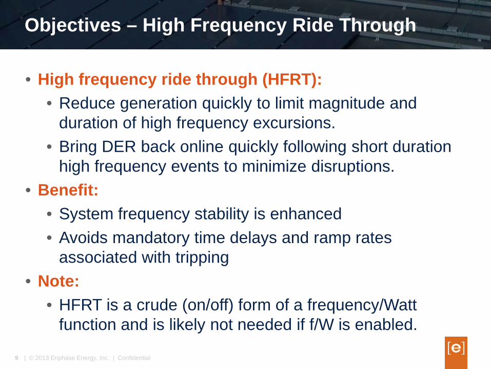
Objectives – High Frequency Ride Through
| © 2013 Enphase Energy, Inc. | Confidential 9
• High frequency ride through (HFRT): • Reduce generation quickly to limit magnitude and
duration of high frequency excursions. • Bring DER back online quickly following short duration
high frequency events to minimize disruptions. • Benefit:
• System frequency stability is enhanced • Avoids mandatory time delays and ramp rates
associated with tripping • Note:
• HFRT is a crude (on/off) form of a frequency/Watt function and is likely not needed if f/W is enabled.
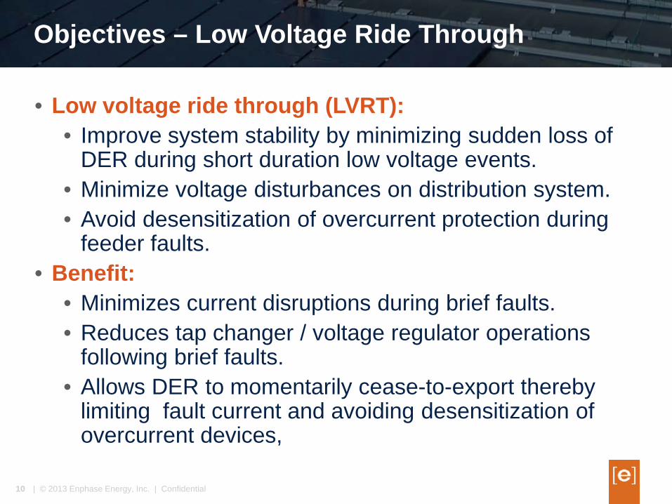
Objectives – Low Voltage Ride Through
| © 2013 Enphase Energy, Inc. | Confidential 10
• Low voltage ride through (LVRT): • Improve system stability by minimizing sudden loss of
DER during short duration low voltage events. • Minimize voltage disturbances on distribution system. • Avoid desensitization of overcurrent protection during
feeder faults. • Benefit:
• Minimizes current disruptions during brief faults. • Reduces tap changer / voltage regulator operations
following brief faults. • Allows DER to momentarily cease-to-export thereby
limiting fault current and avoiding desensitization of overcurrent devices,
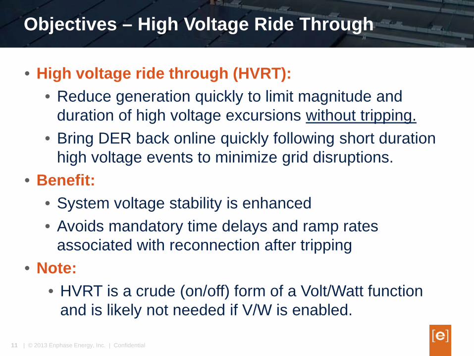
Objectives – High Voltage Ride Through
| © 2013 Enphase Energy, Inc. | Confidential 11
• High voltage ride through (HVRT): • Reduce generation quickly to limit magnitude and
duration of high voltage excursions without tripping. • Bring DER back online quickly following short duration
high voltage events to minimize grid disruptions. • Benefit:
• System voltage stability is enhanced • Avoids mandatory time delays and ramp rates
associated with reconnection after tripping • Note:
• HVRT is a crude (on/off) form of a Volt/Watt function and is likely not needed if V/W is enabled.

Operating Regions
| © 2013 Enphase Energy, Inc. | Confidential 12
• Operating regions are defined by pair points of voltage and time or frequency and time.
• The desired behavior of the DER in each operating region is different and should be tailored to solve a specific problem on the grid. Examples: • Over frequency events, under frequency events • Over voltage events, under voltage events
• Bulk system faults, close in feeder faults, far feeder faults, adjacent feeder faults
• The behavior of the DER must be defined in terms of: • What happens as the grid condition enters the region • What happens as the grid condition exits the region • Will be different depending on time duration of the
excursion
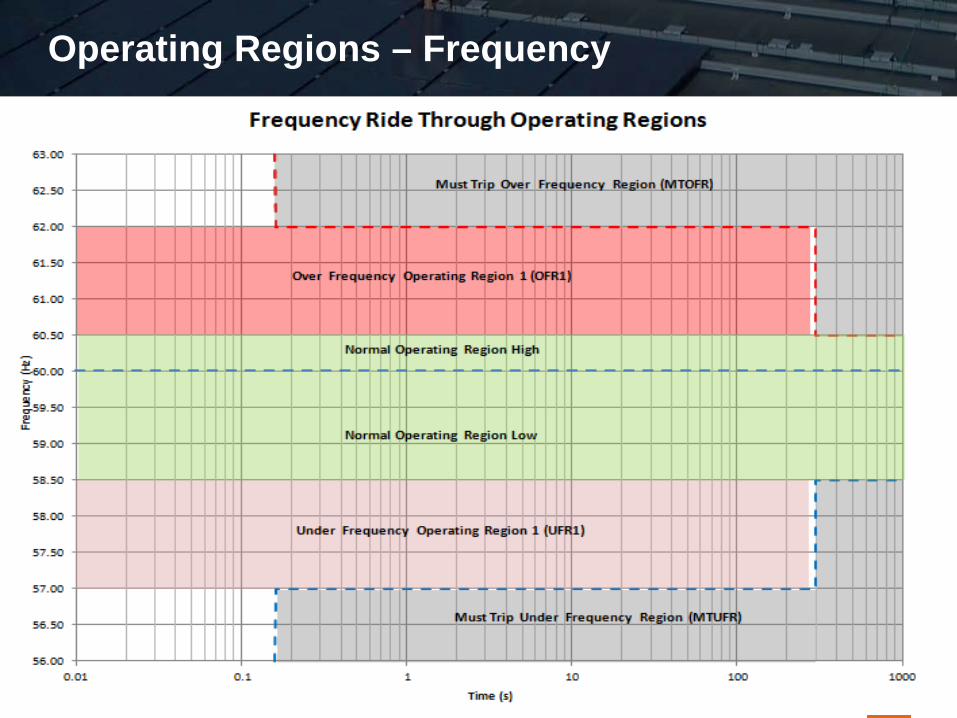
Operating Regions – Frequency
| © 2013 Enphase Energy, Inc. | Confidential 13
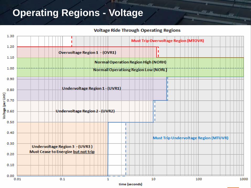
Operating Regions - Voltage
| © 2013 Enphase Energy, Inc. | Confidential 14

Operating Modes
| © 2013 Enphase Energy, Inc. | Confidential 15
• Historically inverter based DER has operated only in one of two modes. • Normal Operation – full available current • Tripped – offline
• Ride through requirements have introduced a new mode - “Momentary Cessation” (placeholder term) • The mode in which the DER has ceased to energize the
grid BUT has not tripped. • The difference between momentary cessation and
tripped is determined by: • Duration of the excursion • Criteria for “Return to Service” • Ramp rates limitations during “Return to Service”
Return To Service Behaviors
| © 2013 Enphase Energy, Inc. | Confidential 16
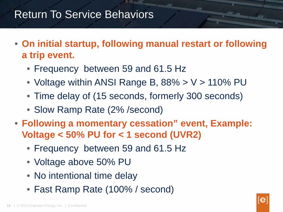
• On initial startup, following manual restart or following a trip event. • Frequency between 59 and 61.5 Hz • Voltage within ANSI Range B, 88% > V > 110% PU • Time delay of (15 seconds, formerly 300 seconds) • Slow Ramp Rate (2% /second)
• Following a momentary cessation” event, Example: Voltage < 50% PU for < 1 second (UVR2) • Frequency between 59 and 61.5 Hz • Voltage above 50% PU • No intentional time delay • Fast Ramp Rate (100% / second)
CA Rule 21 Proposed Settings
| © 2013 Enphase Energy, Inc. | Confidential 17
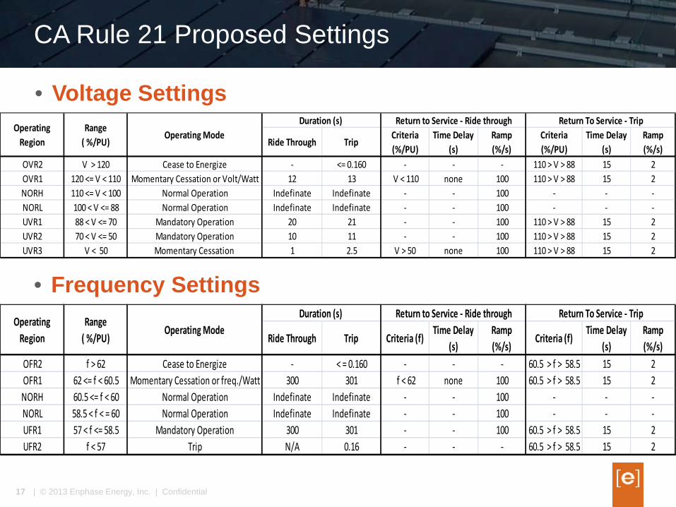
• Voltage Settings
Ride Through Trip Criteria (%/PU)
Time Delay (s)
Ramp (%/s)
Criteria (%/PU)
Time Delay (s)
Ramp (%/s)
OVR2 V > 120 Cease to Energize - <= 0.160 - - - 110 > V > 88 15 2OVR1 120 <= V < 110 Momentary Cessation or Volt/Watt 12 13 V < 110 none 100 110 > V > 88 15 2NORH 110 <= V < 100 Normal Operation Indefinate Indefinate - - 100 - - -NORL 100 < V <= 88 Normal Operation Indefinate Indefinate - - 100 - - -UVR1 88 < V <= 70 Mandatory Operation 20 21 - - 100 110 > V > 88 15 2UVR2 70 < V <= 50 Mandatory Operation 10 11 - - 100 110 > V > 88 15 2UVR3 V < 50 Momentary Cessation 1 2.5 V > 50 none 100 110 > V > 88 15 2
Operating Region
Range ( %/PU)
Operating ModeReturn to Service - Ride through Return To Service - TripDuration (s)
• Frequency Settings
Ride Through Trip Criteria (f)Time Delay
(s)Ramp (%/s)
Criteria (f)Time Delay
(s)Ramp (%/s)
OFR2 f > 62 Cease to Energize - < = 0.160 - - - 60.5 > f > 58.5 15 2OFR1 62 <= f < 60.5 Momentary Cessation or freq./Watt 300 301 f < 62 none 100 60.5 > f > 58.5 15 2NORH 60.5 <= f < 60 Normal Operation Indefinate Indefinate - - 100 - - -NORL 58.5 < f < = 60 Normal Operation Indefinate Indefinate - - 100 - - -UFR1 57 < f <= 58.5 Mandatory Operation 300 301 - - 100 60.5 > f > 58.5 15 2UFR2 f < 57 Trip N/A 0.16 - - - 60.5 > f > 58.5 15 2
Operating Region
Range ( %/PU)
Operating ModeDuration (s) Return to Service - Ride through Return To Service - Trip
Regulatory Issues
| © 2013 Enphase Energy, Inc. | Confidential 18
• IEEE 1547 / 1547.1 does not yet consider ride through • 1547 is currently under revision and will add ride
through requirements. • Once 1547 revision is complete 1547.1 test procedures
can be developed. • UL 1741 will address ride through, real / reactive power
functions, and new advanced anti-islanding as optional tests. • Publication likely in Q1 2015
• Suggested adoption schedule • Permissive upon publication of revised 1741 • Mandatory on expiration of adoption interval, typically
18 months
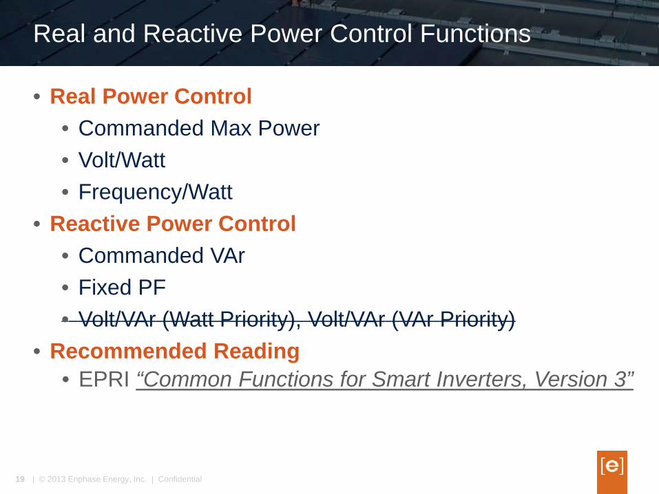
Real and Reactive Power Control Functions
| © 2013 Enphase Energy, Inc. | Confidential 19
• Real Power Control • Commanded Max Power • Volt/Watt • Frequency/Watt
• Reactive Power Control • Commanded VAr • Fixed PF • Volt/VAr (Watt Priority), Volt/VAr (VAr Priority)
• Recommended Reading • EPRI “Common Functions for Smart Inverters, Version 3”
Questions
| © 2013 Enphase Energy, Inc. | Confidential 20
Thank you for your attention
John Berdner [email protected]