inventor manual idi
DESCRIPTION
Inventor Manual IDITRANSCRIPT
66129903852
IDI-09IDI-12IDI-18IDI-24IDI-36IDI-45IDI-50IDI-60
Duct Unit
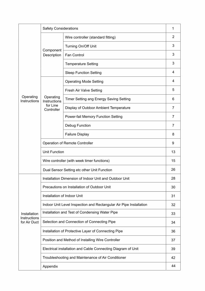
Safety Considerations 1
2
Fan Control
3
Temperature Setting
3 Component Description
Sleep Function Setting
3
Operating Mode Setting
4
Fresh Air Valve Setting
4
5
Timer Setting ang Energy Saving Setting 6
Display of Outdoor Ambient Temperature 7
Power-fail Memory Function Setting 7
Debug Function 7
Operating Instructions
for Line Controller
Failure Display 8
Operation of Remote Controller 9
Unit Function 13
15
Operating Instructions
Installation Dimension of Indoor Unit and Outdoor Unit
26
Precautions on Installation of Outdoor Unit
28
Installation of Indoor Unit
30
Indoor Unit Level Inspection and Rectangular Air Pipe Installation
31
32
Installation and Test of Condensing Water Pipe
33
Installation of Protective Layer of Connecting Pipe
34
Position and Method of Installing Wire Controller
36
Electrical installation and Cable Connecting Diagram of Unit
37
Troubleshooting and Maintenance of Air Conditioner
39
Appendix
42
44
Installation Instructions for Air Duct
Wire controller (with week timer functions)
Dual Sensor Setting etc other Unit Function
Turning On/Off Unit
Wire controller (standard fitting)
Selection and Connection of Connecting Pipe
1
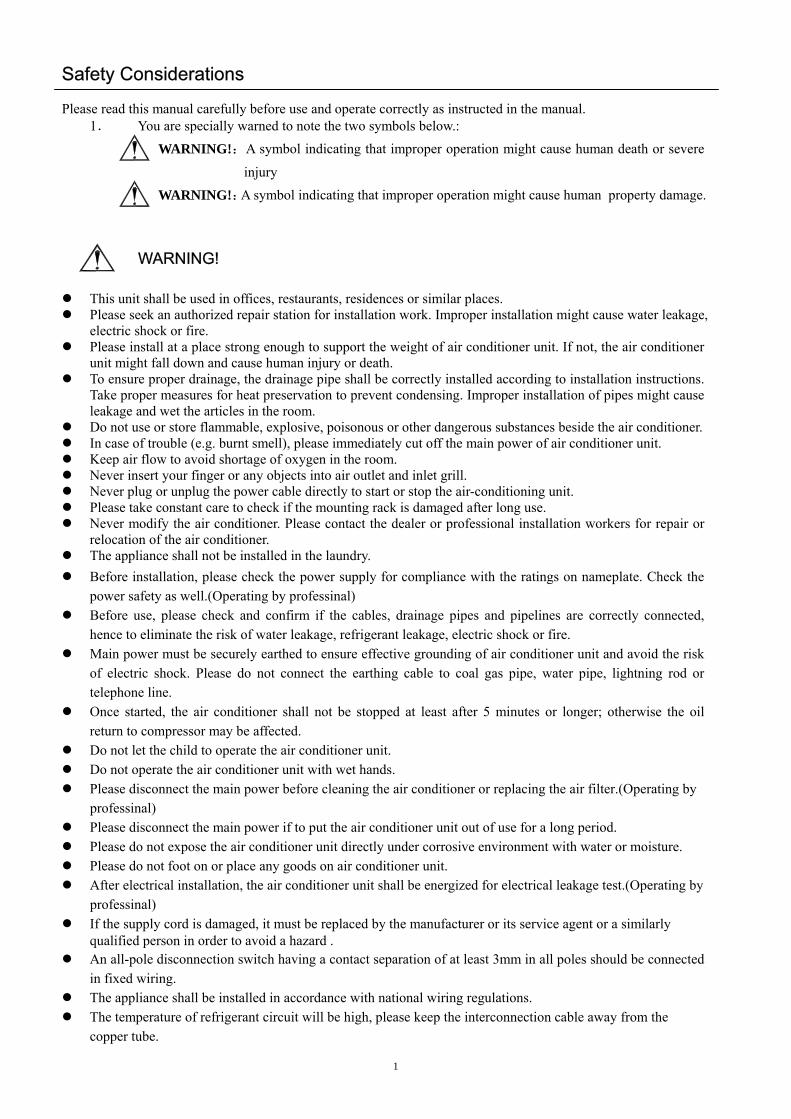
Safety Considerations Please read this manual carefully before use and operate correctly as instructed in the manual.
1. You are specially warned to note the two symbols below.:
WARNING!:A symbol indicating that improper operation might cause human death or severe
injury WARNING!:A symbol indicating that improper operation might cause human property damage.
This unit shall be used in offices, restaurants, residences or similar places.
WARNING!
Please seek an authorized repair station for installation work. Improper installation might cause water leakage, electric shock or fire.
Please install at a place strong enough to support the weight of air conditioner unit. If not, the air conditioner unit might fall down and cause human injury or death.
To ensure proper drainage, the drainage pipe shall be correctly installed according to installation instructions. Take proper measures for heat preservation to prevent condensing. Improper installation of pipes might cause leakage and wet the articles in the room.
Do not use or store flammable, explosive, poisonous or other dangerous substances beside the air conditioner. In case of trouble (e.g. burnt smell), please immediately cut off the main power of air conditioner unit. Keep air flow to avoid shortage of oxygen in the room. Never insert your finger or any objects into air outlet and inlet grill. Never plug or unplug the power cable directly to start or stop the air-conditioning unit. Please take constant care to check if the mounting rack is damaged after long use. Never modify the air conditioner. Please contact the dealer or professional installation workers for repair or
relocation of the air conditioner. The appliance shall not be installed in the laundry. Before installation, please check the power supply for compliance with the ratings on nameplate. Check the
power safety as well.(Operating by professinal) Before use, please check and confirm if the cables, drainage pipes and pipelines are correctly connected,
hence to eliminate the risk of water leakage, refrigerant leakage, electric shock or fire. Main power must be securely earthed to ensure effective grounding of air conditioner unit and avoid the risk
of electric shock. Please do not connect the earthing cable to coal gas pipe, water pipe, lightning rod or telephone line.
Once started, the air conditioner shall not be stopped at least after 5 minutes or longer; otherwise the oil return to compressor may be affected.
Do not let the child to operate the air conditioner unit. Do not operate the air conditioner unit with wet hands. Please disconnect the main power before cleaning the air conditioner or replacing the air filter.(Operating by
professinal) Please disconnect the main power if to put the air conditioner unit out of use for a long period. Please do not expose the air conditioner unit directly under corrosive environment with water or moisture. Please do not foot on or place any goods on air conditioner unit. After electrical installation, the air conditioner unit shall be energized for electrical leakage test.(Operating by
professinal) If the supply cord is damaged, it must be replaced by the manufacturer or its service agent or a similarly
qualified person in order to avoid a hazard . An all-pole disconnection switch having a contact separation of at least 3mm in all poles should be connected
in fixed wiring. The appliance shall be installed in accordance with national wiring regulations. The temperature of refrigerant circuit will be high, please keep the interconnection cable away from the
copper tube.

Wire controller (standard fitting)
• Never install the wire controller in a place where is water leakage.• Avoid bunping, throwing, tossing or frequently opening the wire controller.
1 Timing display
2Fan speed display (Auto, High speed, Medium speed, Low speed)
3 Defros ting status display
4 Energy saving status display
5 Set temperature display
6 Ambient temperature display
7 Fresh air status display (not supplied)
8 Mode (cooling, dehumidifying,fan, heating, auto)
9 Failure status display
10 Sleep status display
11 Mode key
12 Set temperature increase key
13 Set temperature decr ease key
14 Fan speed key (fresh air setting)
15 Sleep key (outdoor environment temperature check)
16 Timing key
17 ON/OFF key
Composition of wire controller
2
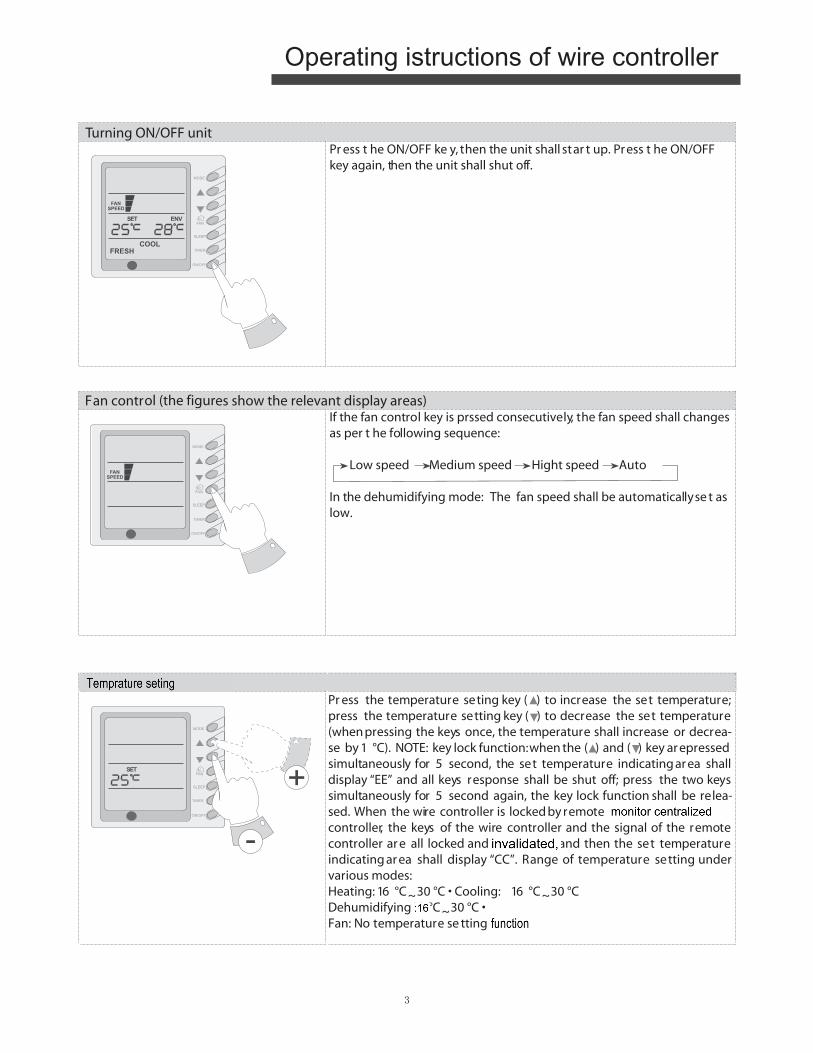
Turning ON/OFF unitPr ess t he ON/OFF ke y, then the unit shall star t up. Press t he ON/OFF key again, then the unit shall shut off.
Fan control (the figures show the relevant display areas)If the fan control key is prssed consecutively, the fan speed shall changes as per t he following sequence:
Low speed Medium speed Hight speed Auto
In the dehumidifying mode: The fan speed shall be automatically se t as low.
3
Temperatur e settingPr ess the temperature seting key ( ) to increase the set temperature; press the temperature setting key ( ) to decrease the set temperature (when pressing the keys once, the temperature shall increase or decrea-se by 1 °C). NOTE: key lock function: when the ( ) and ( ) key ar epressed simultaneously for 5 second, the set temperature indicating ar ea shall display “EE” and all keys response shall be shut off; press the two keys simultaneously for 5 second again, the key lock function shall be relea-sed. When the wire controller is locked by remote monitor or centralized controller, the keys of the wire controller and the signal of the remote controller ar e all locked and invalidated, and then the set temperature indicating ar ea shall display “CC”. Range of temperature setting under various modes:Heating: 16 °C~30 °C • Cooling: 16 °C~30 °CDehumidifying: 16 °C~30 °C • Fan: No temperature se tting function
Operating istructions of wire controller
R
R
R
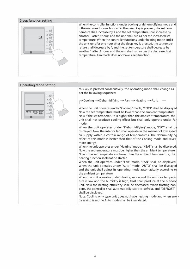
Sleep function settingWhen the controller functions under cooling or dehumidifying mode and if the unit runs for one hour after the sleep key is pressed, the set tem-perature shall increase by 1, and the set temperature shall increase by another 1 after 2 hours and the unit shall run as per the increased set temperature. When the controller functions under heating mode and if the unit runs for one hour after the sleep key is pressed, the set tempe-rature shall decrease by 1, and the set temperature shall decrease by another 1 after 2 hours and the unit shall run as per the decreased set temperature. Fan mode does not have sleep function.
Operating Mode Settingthis key is pressed consecutively, the operating mode shall change as per the following sequence:
Cooling Dehumidifying Fan Heating Auto
When the unit operates under “Cooling” mode, “COOL” shall be displayed. Now the set temperature must be lower than the ambient temperature. Now if the set temperature is higher than the ambient temperature, the unit shall not produce cooling effect but shall only operate under Fan mode. When the unit operates under “Dehumidifying” mode, “DRY” shall be displayed. Now the interior fan shall operate in the manner of low speed air supply within a certain range of temperatures. The dehumidifying effect of this mode is better than that of the Cooling mode and saves more energy. When the unit operates under “Heating” mode, “HEAT” shall be displayed. Now the set temperature must be higher than the ambient temperature; Now if the set temperature is lower than the ambient temperature, the heating function shall not be started.When the unit operates under “Fan” mode, “FAN” shall be displayed. When the unit operates under “Auto” mode, “AUTO” shall be displayed and the unit shall adjust its operating mode automatically according to the ambient temperature.When the unit operates under Heating mode and the outdoor tempera-ture is low and the humidity is high, frost shall produce at the outdoor unit. Now the heating efficiency shall be decreased. When frosting hap-pens, the controller shall automatically start to defrost, and “DEFROST” shall be displayed.Note: Cooling only type unit does not have heating mode and when ener-gy saving is set the Auto mode shall be invalidated.
4
R
R
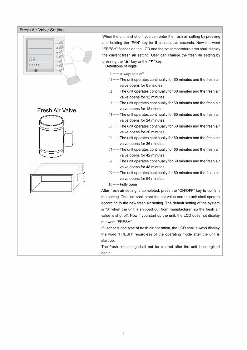
Fresh Air Valve Setting
When the unit is shut off, you can enter the fresh air setting by pressing
and holding the “FAN” key for 5 consecutive seconds. Now the word
“FRESH” flashes on the LCD and the set temperature area shall display
the current fresh air setting. User can change the fresh air setting by
pressing the “▲” key or the “▼” key. Definitions of digits:
00――Always shut off. 01――The unit operates continually for 60 minutes and the fresh air
valve opens for 6 minutes. 02――The unit operates continually for 60 minutes and the fresh air
valve opens for 12 minutes. 03――The unit operates continually for 60 minutes and the fresh air
valve opens for 18 minutes. 04――The unit operates continually for 60 minutes and the fresh air
valve opens for 24 minutes. 05――The unit operates continually for 60 minutes and the fresh air
valve opens for 30 minutes 06――The unit operates continually for 60 minutes and the fresh air
valve opens for 36 minutes 07――The unit operates continually for 60 minutes and the fresh air
valve opens for 42 minutes 08――The unit operates continually for 60 minutes and the fresh air
valve opens for 48 minutes 09――The unit operates continually for 60 minutes and the fresh air
valve opens for 54 minutes 10――Fully open
After fresh air setting is completed, press the “ON/OFF” key to confirm
the setting. The unit shall store the set value and the unit shall operate
according to the new fresh air setting. The default setting of the system
is “0” when the unit is shipped out from manufacturer, so the fresh air
value is shut off. Now if you start up the unit, the LCD does not display
the work “FRESH”.
If user sets one type of fresh air operation, the LCD shall always display
the word “FRESH” regardless of the operating mode after the unit is
start up.
The fresh air setting shall not be cleared after the unit is energized
again.
Fresh Air Valve
FRESH
5
R
�20 seconds af
����
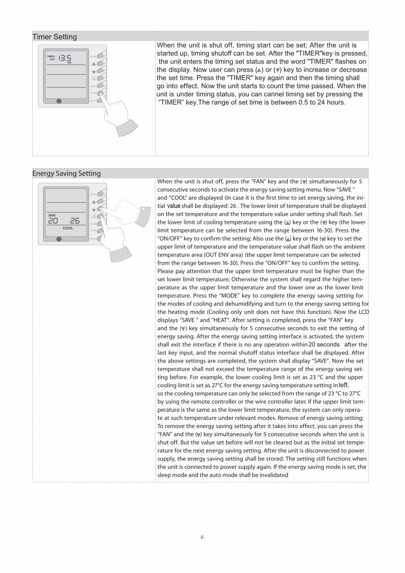
Timer SettingWhen the unit is shut off, timing start can be set; After the unit isstarted up, timing shutoff can be set. After the "TIMER"key is pressed, the unit enters the timing set status and the word "TIMER" flashes onthe display. Now user can press ( ) or ( ) key to increase or decreasethe set time. Press the "TIMER" key again and then the timing shallgo into effect. Now the unit starts to count the time passed. When the
unit is under timing status, you can cannel timing set by pressing the “TIMER” key.The range of set time is between 0.5 to 24 hours.
6
left.
R
R
7
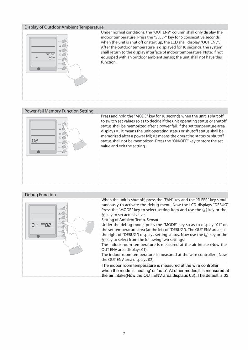
The indoor room temperature is measured at the wire controller when the mode is 'heating' or 'auto'. At other modes,it is measured at the air intake(Now the OUT ENV area displaus 03) ,The default is 03.
R
R
R
8
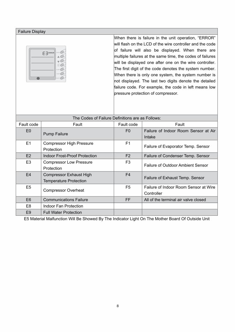
Failure Display
When there is failure in the unit operation, “ERROR” will flash on the LCD of the wire controller and the code of failure will also be displayed. When there are multiple failures at the same time, the codes of failures will be displayed one after one on the wire controller. The first digit of the code denotes the system number. When there is only one system, the system number is not displayed. The last two digits denote the detailed failure code. For example, the code in left means low pressure protection of compressor.
The Codes of Failure Definitions are as Follows: Fault code Fault Fault code Fault
E0 Pump Failure
F0 Failure of Indoor Room Sensor at Air Intake
E1 Compressor High Pressure Protection
F1 Failure of Evaporator Temp. Sensor
E2 Indoor Frost-Proof Protection F2 Failure of Condenser Temp. Sensor E3 Compressor Low Pressure
Protection F3
Failure of Outdoor Ambient Sensor
E4 Compressor Exhaust High Temperature Protection
F4 Failure of Exhaust Temp. Sensor
E5 Compressor Overheat
F5 Failure of Indoor Room Sensor at Wire Controller
E6 Communications Failure FF All of the terminal air valve closed E8 Indoor Fan Protection E9 Full Water Protection
E5 Material Malfunction Will Be Showed By The Indicator Light On The Mother Board Of Outside Unit
SLEEP
TIMER
9
Operation of Remote Controller
SWING FAN
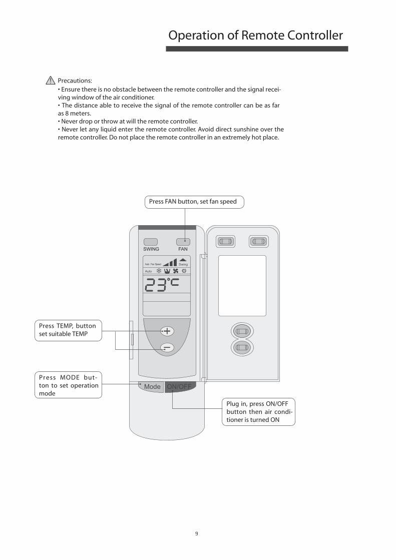
• Ensure there is no obstacle between the remote controller and the signal recei-ving window of the air conditioner. • The distance able to receive the signal of the remote controller can be as far as 8 meters. • Never drop or throw at will the remote controller. • Never let any liquid enter the remote controller. Avoid direct sunshine over the remote controller. Do not place the remote controller in an extremely hot place.
Precautions:
Press FAN button, set fan speed
Press TEMP, button set suitable TEMP
Press MODE but-ton to set operation mode
Plug in, press ON/OFF button then air condi-tioner is turned ON
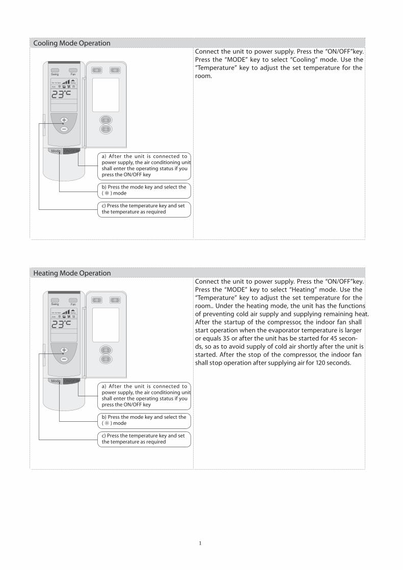
Cooling Mode Operation Connect the unit to power supply. Press the “ON/OFF”key. Press the “MODE” key to select “Cooling” mode. Use the “Temperature” key to adjust the set temperature for the room.
a) After the unit is connected to power supply, the air conditioning unit shall enter the operating status if you press the ON/OFF key
b) Press the mode key and select the ( ) mode
c) Press the temperature key and set the temperature as required
Heating Mode Operation Connect the unit to power supply. Press the “ON/OFF”key. Press the “MODE” key to select “Heating” mode. Use the “Temperature” key to adjust the set temperature for the room.. Under the heating mode, the unit has the functions of preventing cold air supply and supplying remaining heat. After the startup of the compressor, the indoor fan shall start operation when the evaporator temperature is larger or equals 35 or after the unit has be started for 45 secon-ds, so as to avoid supply of cold air shortly after the unit is started. After the stop of the compressor, the indoor fan shall stop operation after supplying air for 120 seconds.
a) After the unit is connected to power supply, the air conditioning unit shall enter the operating status if you press the ON/OFF key
b) Press the mode key and select the ( ) mode
c) Press the temperature key and set the temperature as required
10
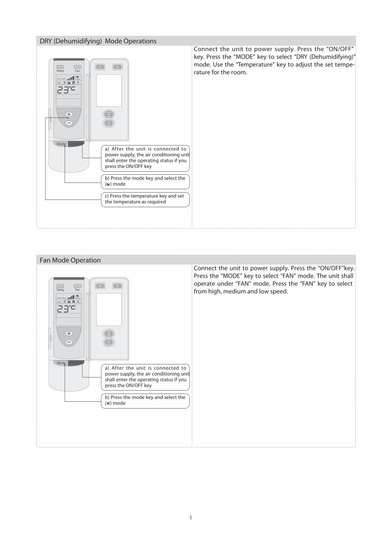
DRY (Dehumidifying) Mode Operations Connect the unit to power supply. Press the “ON/OFF” key. Press the “MODE” key to select “DRY (Dehumidifying)” mode. Use the “Temperature” key to adjust the set tempe-rature for the room.
a) After the unit is connected to power supply, the air conditioning unit shall enter the operating status if you press the ON/OFF key
b) Press the mode key and select the ( ) mode
c) Press the temperature key and set the temperature as required
Fan Mode Operation Connect the unit to power supply. Press the “ON/OFF”key. Press the “MODE” key to select “FAN” mode. The unit shall operate under “FAN” mode. Press the “FAN” key to select from high, medium and low speed.
a) After the unit is connected to power supply, the air conditioning unit shall enter the operating status if you press the ON/OFF key
b) Press the mode key and select the ( ) mode
11
12
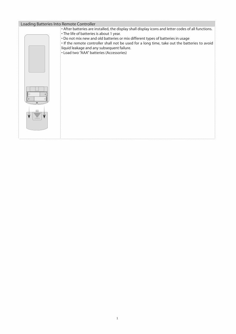
Loading Batteries Into Remote Controller• After batteries are installed, the display shall display icons and letter codes of all functions.• The life of batteries is about 1 year. • Do not mix new and old batteries or mix different types of batteries in usage• If the remote controller shall not be used for a long time, take out the batteries to avoid liquid leakage and any subsequent failure.• Load two “AAA” batteries (Accessories)

U nit Function
• 7DP - Seven days programmer (Accessory not supplied)
1 Unit dispaly
2 Single/group display
3 Timer week display
4 Timer display
5 Timer state display
6 Timer time period display
7 Timer ON/OFF time display
8 Unit on display
9 Unit off display
10 Clock display
11 Confirm button
12Decrease button13
Increase button
14 Cacel/delete button
15 Single/group button
16 Timer/time button
17 ON/OFF button
Composition of programmer wall week
Centralized Control and Week Timer Functions: The centralized control-ler and the weekly timer are integra-ted in the same wire controller. The system has both the centralized con-
trol and the week timing functions. Up to 16 sets of units can be control-led simultaneously by the centralized controller (weekly timer). The weekly timer has the function of invalidating
the lower unit. The weekly timing fun-ction is able to realized four timing ON/OFF periods for any unit every day, so as to achieve fully automatic operation. This WEEKLY TIMER adopts 485 mode to communicate with manual control of every duct type unit, and it can control up to 16 units. Adopting 2-core twisted-pair wire, the lon-gest communication distance of this TIMER is 1200m. After connected to power, the WEEKLY TIMER can display all connected units (sequence of unit is determined by code switch of manual control of every duct type unit). On and off of every duct type unit can be done through the Timer On / Off of this WEEKLY TIMER, and the button shield operation of manual control can be done through shield setting on WEEKLY TIMER. Mode selection and temperature adjust-ment and other operations are done through the manual control at every unit.
13
Week timer Manual control Manual control
LCD LCD LCD16 units in max
Telephone wire box Telephone wire boxTelephone
wire box
Twisted wire with crystal joint
Power supply
On OffPower
Longest distance 1200 m
Corresponding relation between code switch and sequence of unit (NOTE: put-ting code switch to ON means 0)
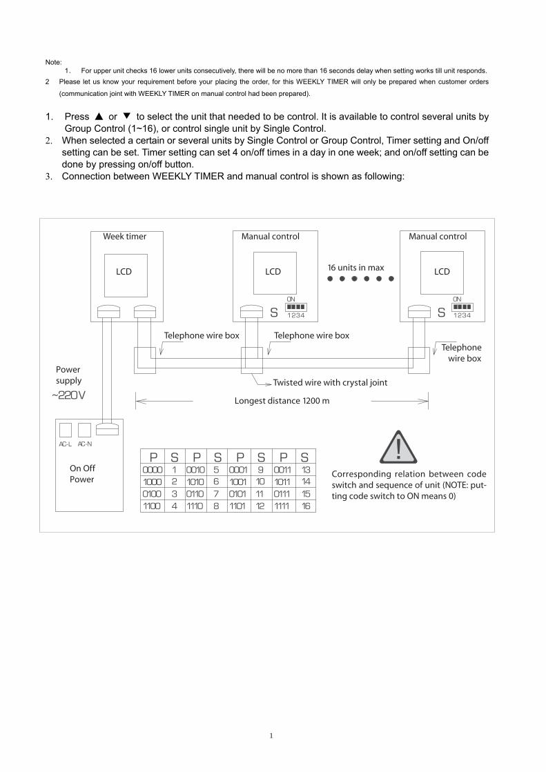
Note: 1. For upper unit checks 16 lower units consecutively, there will be no more than 16 seconds delay when setting works till unit responds.
2 Please let us know your requirement before your placing the order, for this WEEKLY TIMER will only be prepared when customer orders
(communication joint with WEEKLY TIMER on manual control had been prepared). 1. Press ▲ or ▼ to select the unit that needed to be control. It is available to control several units by
Group Control (1~16), or control single unit by Single Control. 2. When selected a certain or several units by Single Control or Group Control, Timer setting and On/off
setting can be set. Timer setting can set 4 on/off times in a day in one week; and on/off setting can be done by pressing on/off button.
3. Connection between WEEKLY TIMER and manual control is shown as following:
14
15
Wire controller (with week timer functions)
WARNING!
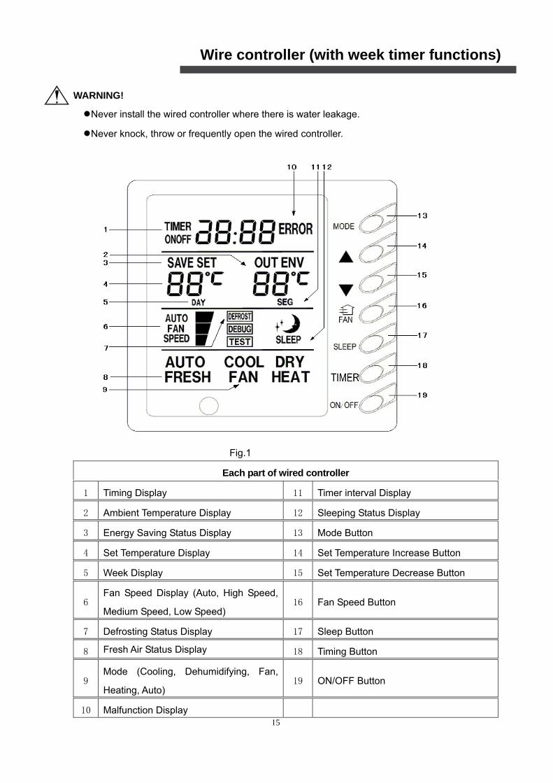
●Never install the wired controller where there is water leakage.
●Never knock, throw or frequently open the wired controller.
Fig.1
Each part of wired controller
1 Timing Display 11 Timer interval Display
2 Ambient Temperature Display 12 Sleeping Status Display
3 Energy Saving Status Display 13 Mode Button
4 Set Temperature Display 14 Set Temperature Increase Button
5 Week Display 15 Set Temperature Decrease Button
6 Fan Speed Display (Auto, High Speed,
Medium Speed, Low Speed) 16 Fan Speed Button
7 Defrosting Status Display 17 Sleep Button
8 Fresh Air Status Display 18 Timing Button
9 Mode (Cooling, Dehumidifying, Fan,
Heating, Auto) 19 ON/OFF Button
10 Malfunction Display
16
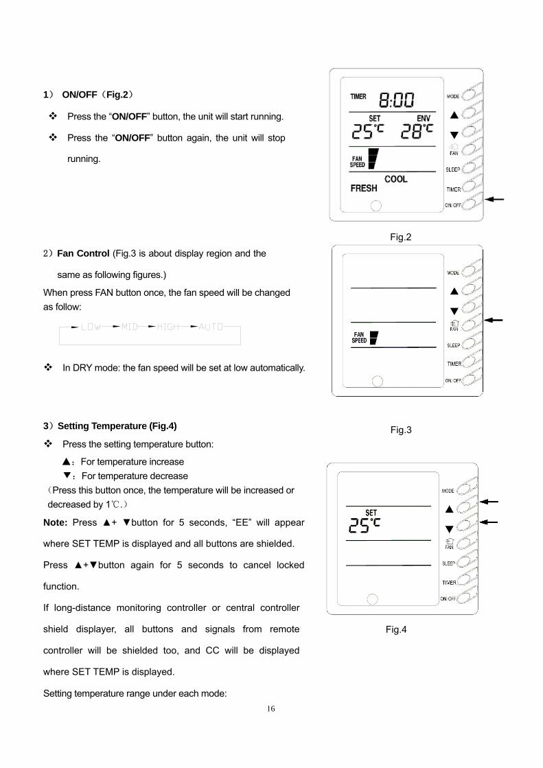
Fig.2
1) ON/OFF(Fig.2)
Press the “ON/OFF” button, the unit will start running.
Press the “ON/OFF” button again, the unit will stop
running.
2)Fan Control (Fig.3 is about display region and the
same as following figures.)
When press FAN button once, the fan speed will be changed as follow:
In DRY mode: the fan speed will be set at low automatically.
3)Setting Temperature (Fig.4)
Press the setting temperature button:
▲:For temperature increase ▼:For temperature decrease
(Press this button once, the temperature will be increased or decreased by 1 .℃)
Note: Press ▲+ ▼button for 5 seconds, “EE” will appear
where SET TEMP is displayed and all buttons are shielded.
Press ▲+▼button again for 5 seconds to cancel locked
function. If long-distance monitoring controller or central controller
shield displayer, all buttons and signals from remote
controller will be shielded too, and CC will be displayed
where SET TEMP is displayed.
Setting temperature range under each mode:
Fig.4
Fig.3
17
HEAT -------- 16℃~30℃
COOL -------- 16℃~30℃
DRY -------- 16℃~30℃
FAN -------- can not be set
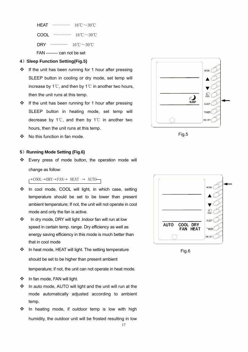
4)Sleep Function Setting(Fig.5)
If the unit has been running for 1 hour after pressing
SLEEP button in cooling or dry mode, set temp will
increase by 1 , and then by 1 in another two hours, ℃ ℃
then the unit runs at this temp.
If the unit has been running for 1 hour after pressing
SLEEP button in heating mode, set temp will
decrease by 1 , and then by 1 in another two ℃ ℃
hours, then the unit runs at this temp.
No this function in fan mode.
5)Running Mode Setting (Fig.6)
Every press of mode button, the operation mode will
change as follow:
→COOL→DRY→FAN→ HEAT → AUTO
In cool mode, COOL will light, in which case, setting
temperature should be set to be lower than present
ambient temperature; If not, the unit will not operate in cool
mode and only the fan is active.
In dry mode, DRY will light .Indoor fan will run at low
speed in certain temp. range. Dry efficiency as well as
energy saving efficiency in this mode is much better than
that in cool mode
In heat mode, HEAT will light. The setting temperature
should be set to be higher than present ambient
temperature; if not, the unit can not operate in heat mode.
In fan mode, FAN will light.
In auto mode, AUTO will light and the unit will run at the
mode automatically adjusted according to ambient
temp.
In heating mode, if outdoor temp is low with high
humidity, the outdoor unit will be frosted resulting in low
Fig.5
Fig.6
18
efficiency of heating, in which case, the controller will
automatically start to defrost with DEFROST displayed.
Note: No heating for cooling-only unit and auto
mode will be shielded after setting energy saving.
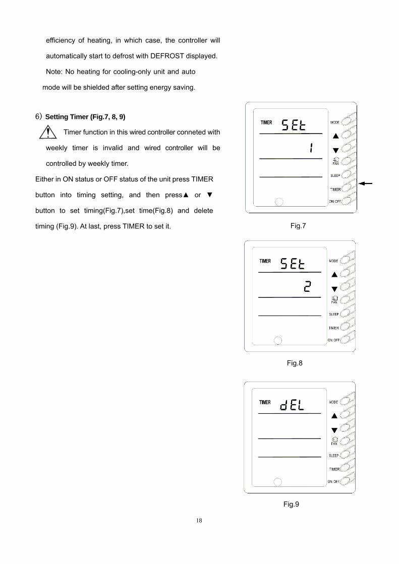
6) Setting Timer (Fig.7, 8, 9)
Timer function in this wired controller conneted with
weekly timer is invalid and wired controller will be
controlled by weekly timer.
Either in ON status or OFF status of the unit press TIMER
button into timing setting, and then press▲ or ▼
button to set timing(Fig.7),set time(Fig.8) and delete
timing (Fig.9). At last, press TIMER to set it.
Fig.7
Fig.8
Fig.9
19
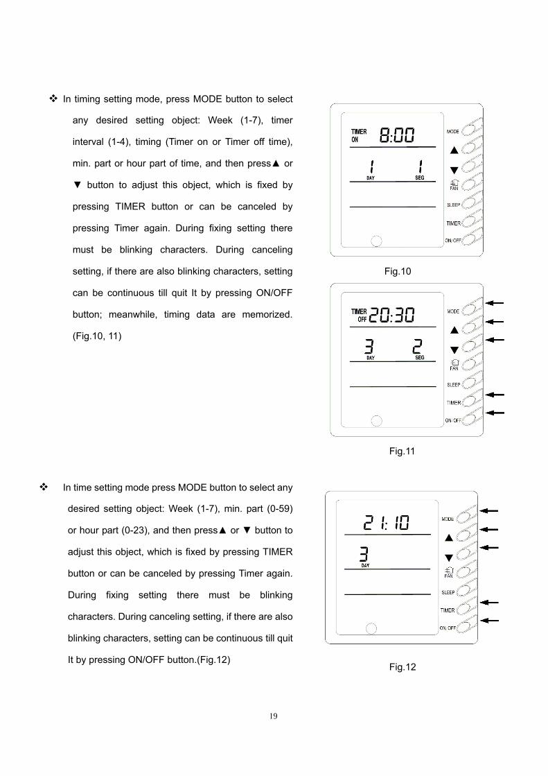
In timing setting mode, press MODE button to select
any desired setting object: Week (1-7), timer
interval (1-4), timing (Timer on or Timer off time),
min. part or hour part of time, and then press▲ or
▼ button to adjust this object, which is fixed by
pressing TIMER button or can be canceled by
pressing Timer again. During fixing setting there
must be blinking characters. During canceling
setting, if there are also blinking characters, setting
can be continuous till quit It by pressing ON/OFF
button; meanwhile, timing data are memorized.
(Fig.10, 11)
In time setting mode press MODE button to select any
desired setting object: Week (1-7), min. part (0-59)
or hour part (0-23), and then press▲ or ▼ button to
adjust this object, which is fixed by pressing TIMER
button or can be canceled by pressing Timer again.
During fixing setting there must be blinking
characters. During canceling setting, if there are also
blinking characters, setting can be continuous till quit
It by pressing ON/OFF button.(Fig.12)
Fig.10
Fig.11
Fig.12

20
In deleting timing status, press ▲ or ▼ button to
select one day of a week, and then press TIMER
button to confirm ,in which case, ”dd” is
displayed .The day also can be canceled by pressing
TIMER button without “dd” displayed. At last, press
ON/OFF button to quit the setting after finish.(Fig.13)
7)Fresh Air Valve Setting (Fig.14)
Press FAN for 5 seconds at unit off into fresh air setting, in
which case FRESH will blink in LCD and fresh air mode will
be displayed where set temp is displayed, which can be
adjusted by pressing ▲ or ▼button. Meaning of each
number:
00-一 Off status all the time.
01――Unit on for 60 min, fresh air valve on for 6 min
02――Unit on for 60 min, fresh air valve on for 12 min
03――Unit on for 60 min, fresh air valve on for 18 min
04――Unit on for 60 min, fresh air valve on for 24 min
05――Unit on for 60 min, fresh air valve on for 30 min
06――Unit on for 60 min, fresh air valve on for 36 min
07――Unit on for 60 min, fresh air valve on for 42 min
08――Unit on for 60 min, fresh air valve on for 48 min
09――Unit on for 60 min, fresh air valve on for 54 min
10――Full open
After adjusting press ON/OFF button to fix, then the
system will memorize the number so that the unit will run
Fig.13
Fig.14
21
in this mode. Factory defaulted value is “0” and the fresh
air valve is in off status, in which case, FRESH won’t be
displayed in LCD after starting the unit.
If fresh air mode (1-10) has been set, in spite of running
mode of system FRESH will be displayed in LCD all the
time at unit on.
Fresh air number can not be cleared if re-energize the unit
after power failure.
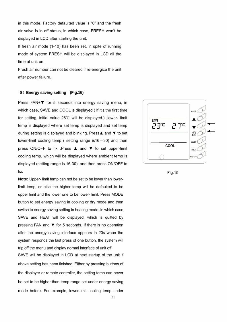
8)Energy saving setting (Fig.15)
Press FAN+▼ for 5 seconds into energy saving menu, in
which case, SAVE and COOL is displayed ( If it’s the first time
for setting, initial value 26 will be displayed.) ,lower℃ - limit
temp is displayed where set temp is displayed and set temp
during setting is displayed and blinking. Press▲ and ▼ to set
lower-limit cooling temp ( setting range is16-30) and then
press ON/OFF to fix .Press ▲ and ▼ to set upper-limit
cooling temp, which will be displayed where ambient temp is
displayed (setting range is 16-30), and then press ON/OFF to
fix.
Note: Upper- limit temp can not be set to be lower than lower-
limit temp, or else the higher temp will be defaulted to be
upper limit and the lower one to be lower- limit. Press MODE
button to set energy saving in cooling or dry mode and then
switch to energy saving setting in heating mode, in which case,
SAVE and HEAT will be displayed, which is quitted by
pressing FAN and ▼ for 5 seconds. If there is no operation
after the energy saving interface appears in 20s when the
system responds the last press of one button, the system will
trip off the menu and display normal interface of unit off.
SAVE will be displayed in LCD at next startup of the unit if
above setting has been finished. Either by pressing buttons of
the displayer or remote controller, the setting temp can never
be set to be higher than temp range set under energy saving
mode before. For example, lower-limit cooling temp under
Fig.15
22
energy saving mode is 23℃ and upper limit is 28℃,so the
user can only set cooling temperature in the range of 23-28℃.
If the same limit temperature is set, the unit will only run under
corresponding mode at this setting temp.
Press Fan+▼ simultaneously for 5s to quit this function if it
has been effective, but former setting value can not be cleared,
which will be as the original value of next setting.
If the power is off, energy saving setting will be memorized,
which continues effectively after the power is on next time.
If energy-saving mode and sleeping mode is setting, auto
mode will be shielded.
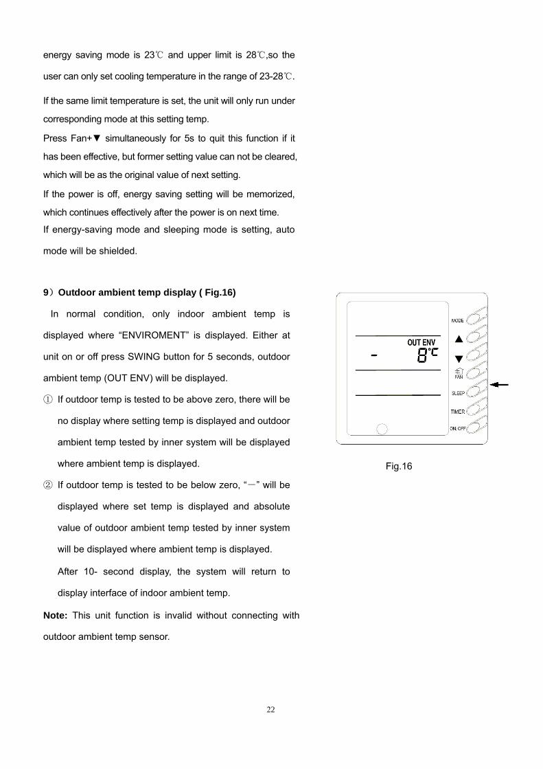
9)Outdoor ambient temp display ( Fig.16)
In normal condition, only indoor ambient temp is
displayed where “ENVIROMENT” is displayed. Either at
unit on or off press SWING button for 5 seconds, outdoor
ambient temp (OUT ENV) will be displayed.
① If outdoor temp is tested to be above zero, there will be
no display where setting temp is displayed and outdoor
ambient temp tested by inner system will be displayed
where ambient temp is displayed.
② If outdoor temp is tested to be below zero, “-” will be
displayed where set temp is displayed and absolute
value of outdoor ambient temp tested by inner system
will be displayed where ambient temp is displayed.
After 10- second display, the system will return to
display interface of indoor ambient temp.
Note: This unit function is invalid without connecting with
outdoor ambient temp sensor.
Fig.16
23
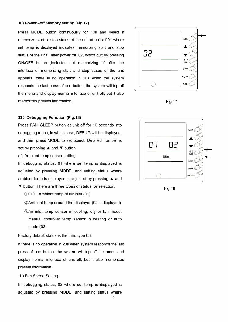
10) Power –off Memory setting (Fig.17)
Press MODE button continuously for 10s and select if
memorize start or stop status of the unit at unit off.01 where
set temp is displayed indicates memorizing start and stop
status of the unit after power off .02, which quit by pressing
ON/OFF button ,indicates not memorizing. If after the
interface of memorizing start and stop status of the unit
appears, there is no operation in 20s when the system
responds the last press of one button, the system will trip off
the menu and display normal interface of unit off, but it also
memorizes present information.
11)Debugging Function (Fig.18)
Press FAN+SLEEP button at unit off for 10 seconds into
debugging menu, in which case, DEBUG will be displayed,
and then press MODE to set object. Detailed number is
set by pressing ▲ and ▼ button.
a)Ambient temp sensor setting
In debugging status, 01 where set temp is displayed is
adjusted by pressing MODE, and setting status where
ambient temp is displayed is adjusted by pressing ▲ and
▼ button. There are three types of status for selection.
①01) Ambient temp of air inlet (01)
②Ambient temp around the displayer (02 is displayed)
③Air inlet temp sensor in cooling, dry or fan mode;
manual controller temp sensor in heating or auto
mode (03)
Factory default status is the third type 03.
If there is no operation in 20s when system responds the last
press of one button, the system will trip off the menu and
display normal interface of unit off, but it also memorizes
present information.
b) Fan Speed Setting
In debugging status, 02 where set temp is displayed is
adjusted by pressing MODE, and setting status where
Fig.17
Fig.18
24
ambient temp is displayed is adjusted by pressing ▲ and
▼ button. There are five types of status for selection.
1. 220V (01 displayed in LCD) (Fan speed
adjustment is unavailable)
2. 200V (02 displayed in LCD)
3. 180V (03 displayed in LCD)
4. 160V (04displayed in LCD)
5. 140V (05 displayed in LCD) Note: Factory default status is the third type 01.
After setting press ON/OFF to fix and quit .If there is no
operation in 20s when system responds the last press of one
button, the system will trip off the menu and display normal
interface of unit off, but it also memorizes present information.
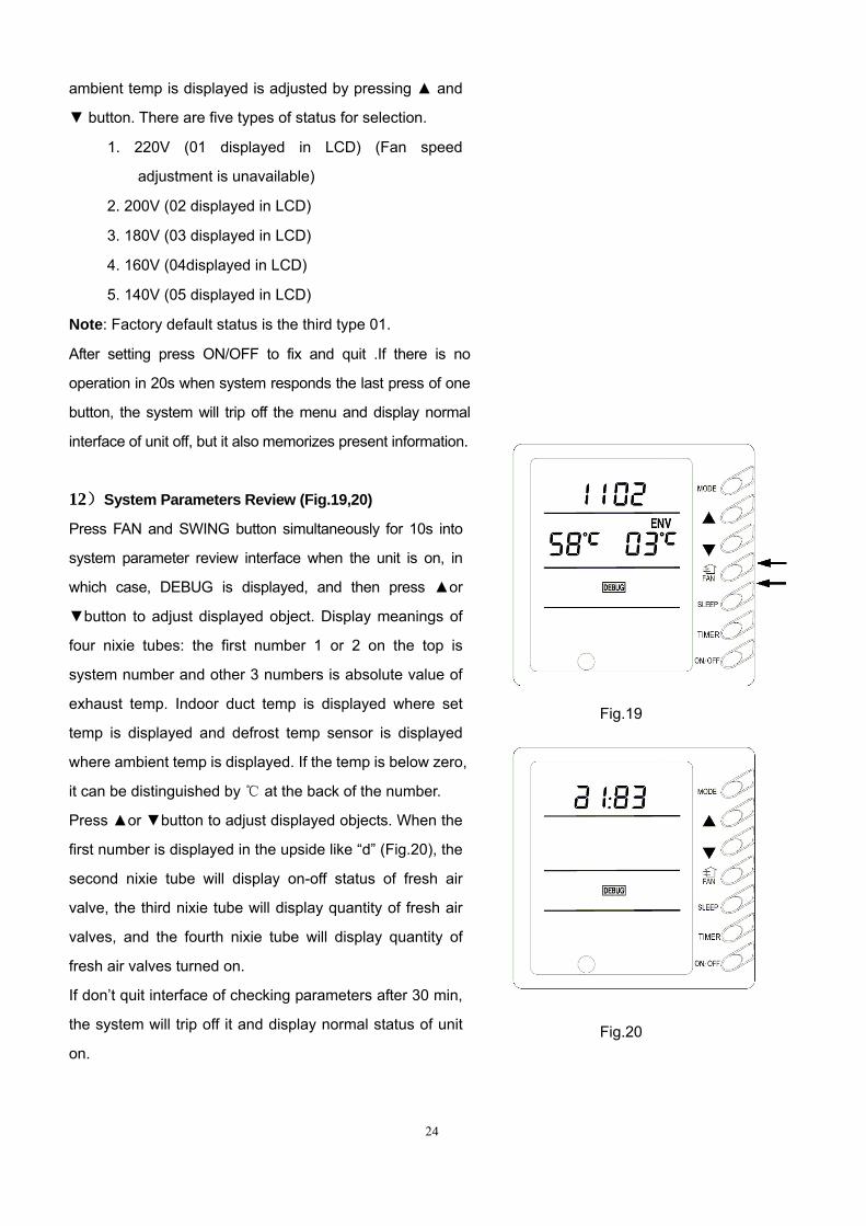
12)System Parameters Review (Fig.19,20)
Press FAN and SWING button simultaneously for 10s into
system parameter review interface when the unit is on, in
which case, DEBUG is displayed, and then press ▲or
▼button to adjust displayed object. Display meanings of
four nixie tubes: the first number 1 or 2 on the top is
system number and other 3 numbers is absolute value of
exhaust temp. Indoor duct temp is displayed where set
temp is displayed and defrost temp sensor is displayed
where ambient temp is displayed. If the temp is below zero,
it can be distinguished by ℃ at the back of the number.
Press ▲or ▼button to adjust displayed objects. When the
first number is displayed in the upside like “d” (Fig.20), the
second nixie tube will display on-off status of fresh air
valve, the third nixie tube will display quantity of fresh air
valves, and the fourth nixie tube will display quantity of
fresh air valves turned on.
If don’t quit interface of checking parameters after 30 min,
the system will trip off it and display normal status of unit
on.
Fig.19
Fig.20
25
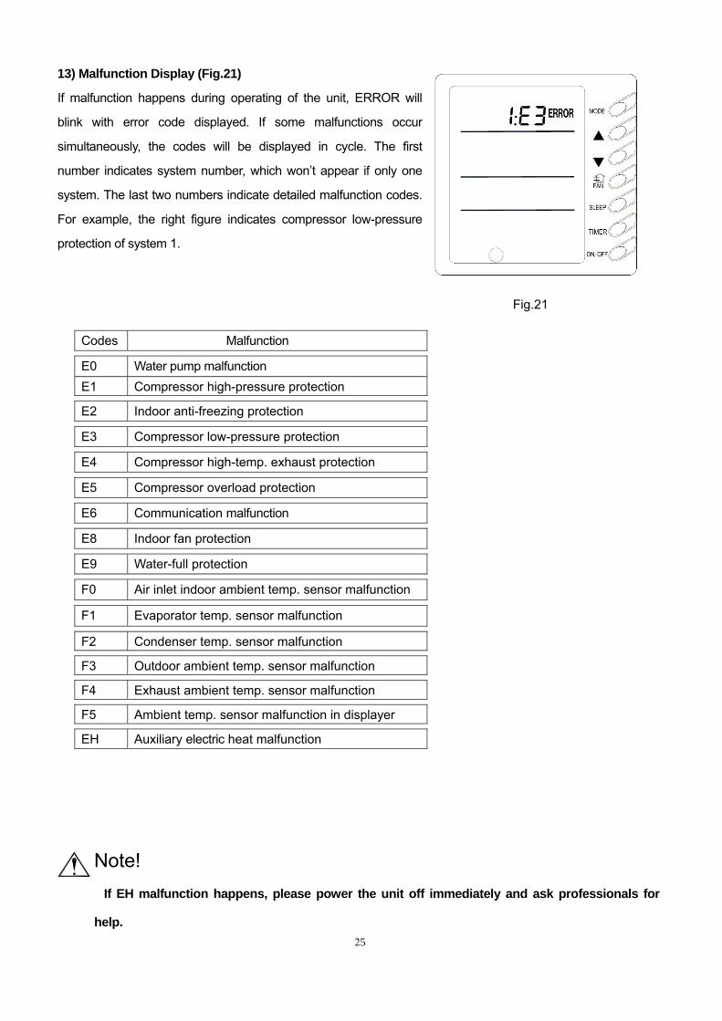
13) Malfunction Display (Fig.21)
If malfunction happens during operating of the unit, ERROR will
blink with error code displayed. If some malfunctions occur
simultaneously, the codes will be displayed in cycle. The first
number indicates system number, which won’t appear if only one
system. The last two numbers indicate detailed malfunction codes.
For example, the right figure indicates compressor low-pressure
protection of system 1.
Codes Malfunction
E0 Water pump malfunction E1 Compressor high-pressure protection
E2 Indoor anti-freezing protection
E3 Compressor low-pressure protection
E4 Compressor high-temp. exhaust protection
E5 Compressor overload protection
E6 Communication malfunction
E8 Indoor fan protection
E9 Water-full protection
F0 Air inlet indoor ambient temp. sensor malfunction
F1 Evaporator temp. sensor malfunction
F2 Condenser temp. sensor malfunction
F3 Outdoor ambient temp. sensor malfunction
F4 Exhaust ambient temp. sensor malfunction
F5 Ambient temp. sensor malfunction in displayer
EH Auxiliary electric heat malfunction
Note! If EH malfunction happens, please power the unit off immediately and ask professionals for
help.
Fig.21
26
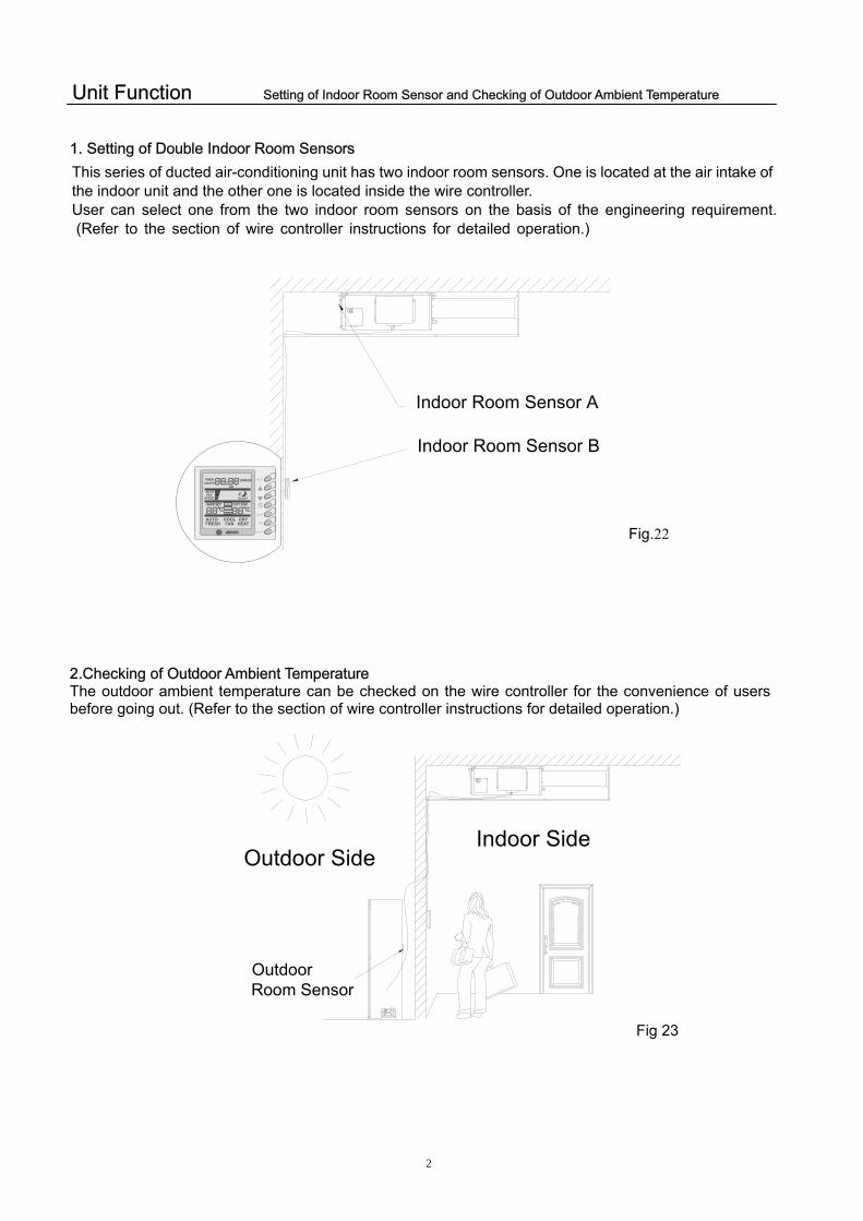
Unit Function Setting of Indoor Room Sensor and Checking of Outdoor Ambient Temperature
1. Setting of Double Indoor Room Sensors
Indoor Room Sensor A
Indoor Room Sensor B
Fig.22
2.Checking of Outdoor Ambient Temperature The outdoor ambient temperature can be checked on the wire controller for the convenience of users before going out. (Refer to the section of wire controller instructions for detailed operation.)
Outdoor Room Sensor
Outdoor SideIndoor Side
Fig 23
This series of ducted air-conditioning unit has two indoor room sensors. One is located at the air intake of the indoor unit and the other one is located inside the wire controller. User can select one from the two indoor room sensors on the basis of the engineering requirement. (Refer to the section of wire controller instructions for detailed operation.)
27
Unit Function Fresh Air Control, Pump
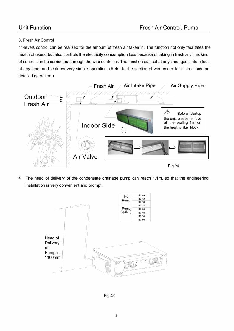
3. Fresh Air Control
11-levels control can be realized for the amount of fresh air taken in. The function not only facilitates the
health of users, but also controls the electricity consumption loss because of taking in fresh air. This kind
of control can be carried out through the wire controller. The function can set at any time, goes into effect
at any time, and features very simple operation. (Refer to the section of wire controller instructions for
detailed operation.)
Fresh Air Air Supply PipeAir Intake Pipe
Air Valve
Outdoor Fresh Air
Indoor Side
Before startupthe unit, please removeall the sealing film onthe healthy filter block
Fig.24
4. The head of delivery of the condensate drainage pump can reach 1.1m, so that the engineering
installation is very convenient and prompt.
Head of Delivery of Pump is 1100mm
Pump
NoPump
(option)
Fig.25
IDI 09IDI 12IDI 18IDI 24IDI 36IDI 45IDI 50IDI 60

Instructions of Unit Installation Profile Dimensions of Indoor Unit Profile Dimensions of Indoor Unit
A ir In take
D rainage P ipe
E lectric BoxG as P ipeLiquid P ipe
A ir In take
F
I
Fig.26
BF
DC
A
G
H
I J
Drainage PipeGas Pipe Liquid Pipe Electric Box
Air Intake
E
Be suit for:
28
IDI 09IDI 12IDI 18
Be suit for:
IDI 24IDI 36IDI 45IDI 50IDI 60
Fig.27
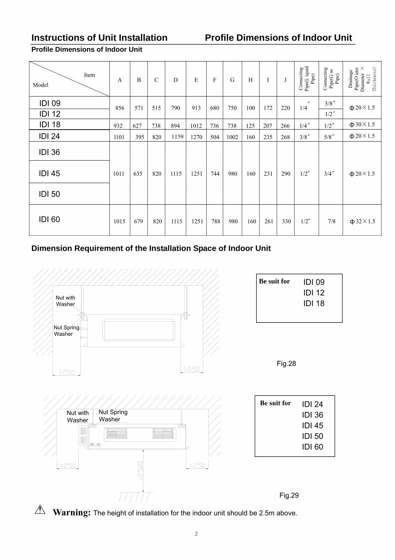
Instructions of Unit Installation Profile Dimensions of Indoor Unit Profile Dimensions of Indoor Unit
1101 395 820 1159 1270 504 1002 160 235 268 3/8〞 5/8〞 ф 20×1.5
1011 635 820 1115 1251 744 980 160 231 290 1/2〞 3/4〞 ф 20×1.5
1015 679 820 1115 1251 788 980 160 261 330 1/2〞 ф 32×1.5
Item
ModelA B C D E F G H I J
Con
nect
ing diuqi
L( epiPPi
pe)
Con
nect
ing sa
G( epiPPi
pe)
Dra
inag
e retuO( epiP D
iam
eter
×
Wall
Thickness)
3/8〞856 571 515 790 913 680 750 100 172 220 1/4〞
1/2〞ф 20×1.5
932 627 738 894 1012 736 738 125 207 266 1/4〞 1/2〞 ф 30×1.5
Dimension Requirement of the Installation Space of Indoor Unit
Nut with Washer
Nut Spring Washer
Be suit for:
29
Warning: The height of installation for the indoor unit should be
Nut with Washer
Nut Spring Washer
7/8��
IDI 24
IDI 36
IDI 45
IDI 50
IDI 60
IDI 09IDI 12IDI 18
IDI 09IDI 12IDI 18
Fig.28
Be suit for:
IDI 24IDI 36IDI 45IDI 50IDI 60
2.5m above.
Fig.29
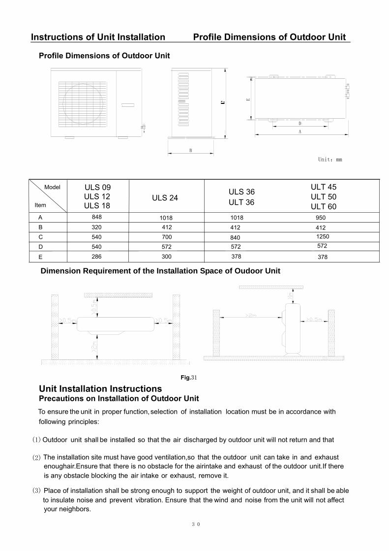
Instructions of Unit Installation Profile Dimensions of Outdoor Unit
Profile Dimensions of Outdoor Unit
E
A
D
B
Unit:mm
4121250572
378
Model
Item
B 320 412
C 540 700
D 540 572
E 286 300
9501018
412
840572
378
1018848A
Dimension Requirement of the Installation Space of Oudoor Unit
ULS 09ULS 12ULS 18
ULS 24ULS 36ULT 36
ULT 45ULT 50ULT 60
Fig.31
30
Unit Installation Instructions Precautions on Installation of Outdoor Unit To ensure the unit in proper function, selection of installation location must be in accordance with following principles:
(1)Outdoor tinu shall be dellatsni os eht taht ria taht dna nruter ton lliw tinu roodtuo yb degrahcsid
(2) noitallatsni ehT doog evah tsum etis os ,noitalitnev taht roodtuo eht tinu nac ekat ni dna exhaust erusnE .ria hguone taht si ereht dna ekatni ria eht rof elcatsbo on tsuahxe fo eht roodtuo ereht fI .tinu
gnikcolb elcatsbo yna si eht ekatni ria ro ,tsuahxe .ti evomer
(3) noitallatsni fo ecalP hguone gnorts eb llahs ot troppus eht thgiew fo ,tinu roodtuo dna ti eb llahs able etalusni ot dna esion tneverp .noi tarbiv erusnE taht dniw eht dna esion morf lliw tinu eht tceffa ton
.srobhgien ruoy

Unit Installation Instructions Installation of Indoor Unit (4) Avoid direct sunshine over the unit. It is better to set up a sun shield as the protection. (5) Place of installation must be able to drain the rainwater and defrosting water. (6) Place of installation must ensure the machine will not be buried under snow or subject to the
influence of rubbish or oil fog. (7) The installation site must be at a place where the air exhaust outlet does not face strong wind.
Installation of Indoor Unit 1. Selection of Installation Site (1) Ensure the top hanging piece has strong strength to withstand the weight of the unit. (2) The drainage pipe has convenient flow of water. (3) There is no obstacle blocking the air intake and exhaust outlet, so as to ensure sound air circulation. (4) The installation spaces required by the drawing must be ensured, so as to provide enough space for
the service and maintenance. (5) The installation site must be far away from heat source, leakage of inflammable gas or smoke. (6) The indoor unit is of ceiling mount (indoor unit is hidden inside the ceiling). (7) The indoor and outdoor units, the power cable and the connecting electrical lines must be at least 1
meter from any TV set or radio. This is to avoid image interference or noise of the TV set or radio. (Even if the distance is 1 meter, noise can also exist if there is strong electric wave.)
2. Installation of Indoor Unit (1) Insert a M10 expansion bolt into the hole. Drive a nail into the bolt. Refer to the profile dimensions
drawing of the indoor unit for the distance between the holes. Refer to Figure 32 for the installation of the expansion bolt.
Fig. 32
(2) Install the hanger onto the indoor unit as Figure 33 s(3) Install the indoor unit at the ceiling as Figure 34 sho
I
Fi
CeiliScre
Air Intake
31
Fig. 33
hows. ws.
送风
螺母挂钩螺杆 m
m
I放大
g. 34
Nut
Screw
Hanger
Air-conditioning Unit
Hanger ng-mount w
Air Supply
I Enlargement
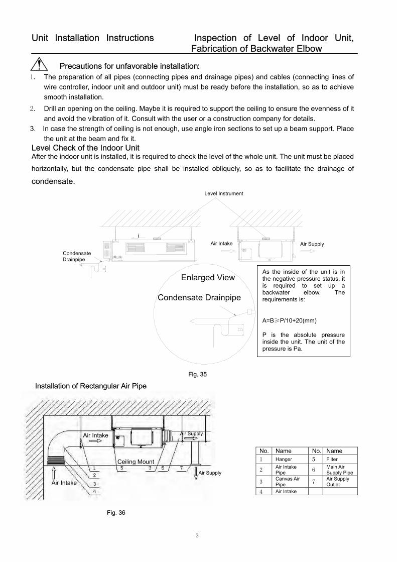
Unit Installation Instructions Inspection of Level of Indoor Unit, Fabrication of Backwater Elbow
Precautions for unfavorable installation: 1. The preparation of all pipes (connecting pipes and drainage pipes) and cables (connecting lines of
wire controller, indoor unit and outdoor unit) must be ready before the installation, so as to achieve smooth installation.
2. Drill an opening on the ceiling. Maybe it is required to support the ceiling to ensure the evenness of it and avoid the vibration of it. Consult with the user or a construction company for details.
3. In case the strength of ceiling is not enough, use angle iron sections to set up a beam support. Place the unit at the beam and fix it.
Level Check of the Indoor Unit After the indoor unit is installed, it is required to check the level of the whole unit. The unit must be placed
horizontally, but the condensate pipe shall be installed obliquely, so as to facilitate the drainage of
condensate.
Air SupplyAir Intakei
Condensate Drainpipe
Level Instrument
Enlarged View
Condensate Drainpipe
As the inside of the unit is inthe negative pressure status, itis required to set up abackwater elbow. Therequirements is: A=B≥P/10+20(mm) P is the absolute pressureinside the unit. The unit of thepressure is Pa.
Fig. 35
Installation of Rectangular Air Pipe
Air SupplyAir Intake
No. Name No. Name 1 Hanger 5 Filter
2 Air Intake Pipe 6
Main Air Supply Pipe
3 Canvas Air Pipe 7
Air Supply Outlet
4 Air Intake
Ceiling Mount
Air Supply
Air Intake
Fig. 36
32
33
Unit Installation Instructions Installation of Drainage Pipeline
Cautions: The air supply pipe, the air intake pipe and the fresh air pipe must be covered with a layer of
thermal insulation, so as to avoid thermal leakage and condensation. Firstly apply liquid nail on the pipes, then attach the thermal insulation cotton with a layer of tinfoil. Use the liquid nail cover to fix it. Lastly use tinfoil adhesive tape to carefully seal the joints; other good thermal insulation materials can also be used. The air supply pipes and the air intake pipes shall be fixed to the prefabricated boards of the
ceiling by using iron supports. The joints of the pipes must be sealed by glue so as to avoid leakage.
The design and installation of air pipes must be in conformity with the relevant state engineering criteria.
The edge of the air intake pipe must be at least 150mm away from the wall. The air intake must be covered with filter.
Silencing and shock absorption shall be considered in the design and installation of the air pipes. Additionally, the noise source must be far away from where people stay. The air intake shall not be located above the place where users stay (offices and rest places, etc.).
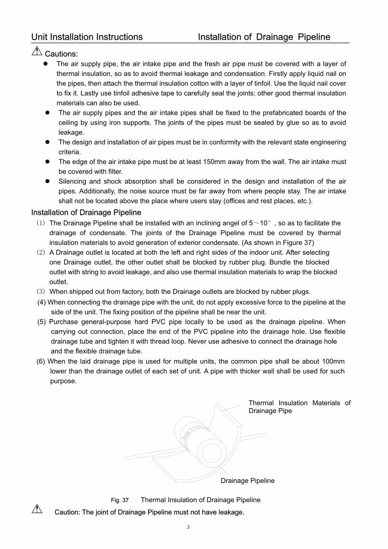
Installation of Drainage Pipeline (1) The Drainage Pipeline shall be installed with an inclining angel of 5~10°, so as to facilitate the
drainage of condensate. The joints of the Drainage Pipeline must be covered by thermal insulation materials to avoid generation of exterior condensate. (As shown in Figure 37)
(2) A Drainage outlet is located at both the left and right sides of the indoor unit. After selecting one Drainage outlet, the other outlet shall be blocked by rubber plug. Bundle the blocked outlet with string to avoid leakage, and also use thermal insulation materials to wrap the blocked outlet.
(3) When shipped out from factory, both the Drainage outlets are blocked by rubber plugs.
管盖
冷
保温层Thermal Insulation Materials ofDrainage Pipe
Fig. 37 Thermal Insulation of Drainage Pipeline
Caution: The joint of Drainage Pipeline must not have leakage.
Drainage Pipeline
(4) When connecting the drainage pipe with the unit, do not apply excessive force to the pipeline at the side of the unit. The fixing position of the pipeline shall be near the unit.
(5) Purchase general-purpose hard PVC pipe locally to be used as the drainage pipeline. When carrying out connection, place the end of the PVC pipeline into the drainage hole. Use flexible drainage tube and tighten it with thread loop. Never use adhesive to connect the drainage hole
and the flexible drainage tube. (6) When the laid drainage pipe is used for multiple units, the common pipe shall be about 100mm
lower than the drainage outlet of each set of unit. A pipe with thicker wall shall be used for such purpose.
Unit Installation Instructions Installation of Condensate Pipe
Testing of Drainage System
(1) After the electrical installation is completed, carry out the testing of the drainage system.
(2) During the test, check if the water correctly flows through the pipelines. Carefully observe the joints to ensure that there is no leakage. If the unit is to be installed in a new house, carry out testing before decorating the ceiling.
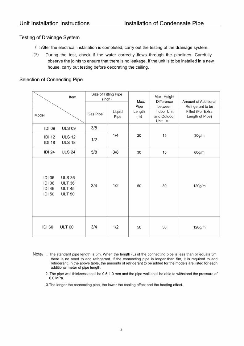
Selection of Connecting Pipe
Size of Fitting Pipe (Inch) Item
Model
Max. Height Difference between
Indoor Unit and Outdoor Unit m
3/8
1/2 1/4 20 15 30g/m
5/8 3/8 30 15 60g/m
3/4
1/2
50 30 120g/m
3/4 1/2 50 30 120g/m
Gas Pipe Liquid Pipe
Max. Pipe
Length (m)
Amount of Additional Refrigerant to be Filled (For Extra Length of Pipe)
Note:1 The standard pipe length is 5m. When the length (L) of the connecting pipe is less than or equals 5m, there is no need to add refrigerant. If the connecting pipe is longer than 5m, it is required to add refrigerant. In the above table, the amounts of refrigerant to be added for the models are listed for each additional meter of pipe length.
2. The pipe wall thickness shall be 0.5-1.0 mm and the pipe wall shall be able to withstand the pressure of 6.0 MPa.
3.The longer the connecting pipe, the lower the cooling effect and the heating effect.
34
IDI 09 ULS 09
IDI 12 ULS 12IDI 18 ULS 18
IDI 24 ULS 24
IDI 36 ULS 36IDI 36 ULT 36IDI 45 ULT 45IDI 50 ULT 50
IDI 60 ULT 60
35
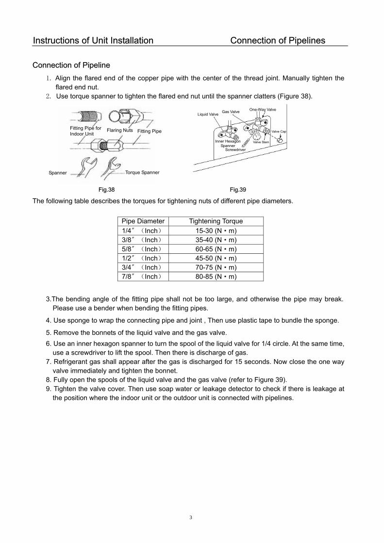
Instructions of Unit Installation Connection of Pipelines
Connection of Pipeline 1. Align the flared end of the copper pipe with the center of the thread joint. Manually tighten the
flared end nut. 2. Use torque spanner to tighten the flared end nut until the spanner clatters (Figure 38).
One-Way Valve Gas ValveLiquid Valve
Fitting Pipe for Indoor Unit
Flaring Nuts Fitting Pipe Valve Cap
Inner Hexagon Spanner
Screwdriver Valve Stem
Torque Spanner Spanner
Fig.38 Fig.39
The following table describes the torques for tightening nuts of different pipe diameters.
3.The bending angle of the fitting pipe shall not be too large, and otherwise the pipe may break. Please use a bender when bending the fitting pipes.
4. Use sponge to wrap the connecting pipe and joint , Then use plastic tape to bundle the sponge.
5. Remove the bonnets of the liquid valve and the gas valve. 6. Use an inner hexagon spanner to turn the spool of the liquid valve for 1/4 circle. At the same time,
use a screwdriver to lift the spool. Then there is discharge of gas. 7. Refrigerant gas shall appear after the gas is discharged for 15 seconds. Now close the one way
valve immediately and tighten the bonnet. 8. Fully open the spools of the liquid valve and the gas valve (refer to Figure 39). 9. Tighten the valve cover. Then use soap water or leakage detector to check if there is leakage at
the position where the indoor unit or the outdoor unit is connected with pipelines.
Pipe Diameter Tightening Torque 1/4〞(Inch) 15-30 (N·m) 3/8〞(Inch) 35-40 (N·m) 5/8〞(Inch) 60-65 (N·m) 1/2〞(Inch) 45-50 (N·m) 3/4〞(Inch) 70-75 (N·m) 7/8〞(Inch) 80-85 (N·m)
36
Instructions of Unit Installation Installation of Connecting Pipe
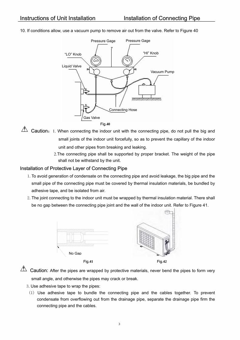
10. If conditions allow, use a vacuum pump to remove air out from the valve. Refer to Figure 40
Pressure Gage Pressure Gage
“LO” Knob
“HI” Knob
Liq id Valve u Vacuum Pump
Connecting Hose
Gas Valve
Fig.40 Caution:1. When connecting the indoor unit with the connecting pipe, do not pull the big and
small joints of the indoor unit forcefully, so as to prevent the capillary of the indoor
unit and other pipes from breaking and leaking. 2.The connecting pipe shall be supported by proper bracket. The weight of the pipe
shall not be withstand by the unit. Installation of Protective Layer of Connecting Pipe 1.To avoid generation of condensate on the connecting pipe and avoid leakage, the big pipe and the
small pipe of the connecting pipe must be covered by thermal insulation materials, be bundled by
adhesive tape, and be isolated from air.
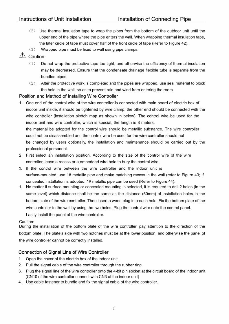
2.The joint connecting to the indoor unit must be wrapped by thermal insulation material. There shall
be no gap between the connecting pipe joint and the wall of the indoor unit. Refer to Figure 41.
无 间隙
Fig.41 Fig.42
No Gap
Caution: After the pipes are wrapped by protective materials, never bend the pipes to form very
small angle, and otherwise the pipes may crack or break.
3.Use adhesive tape to wrap the pipes: (1) Use adhesive tape to bundle the connecting pipe and the cables together. To prevent
condensate from overflowing out from the drainage pipe, separate the drainage pipe firm the connecting pipe and the cables.
37
Instructions of Unit Installation Installation of Connecting Pipe
(2) Use thermal insulation tape to wrap the pipes from the bottom of the outdoor unit until the upper end of the pipe where the pipe enters the wall. When wrapping thermal insulation tape, the later circle of tape must cover half of the front circle of tape (Refer to Figure 42).
(3) Wrapped pipe must be fixed to wall using pipe clamps.
Caution: (1) Do not wrap the protective tape too tight, and otherwise the efficiency of thermal insulation
may be decreased. Ensure that the condensate drainage flexible tube is separate from the bundled pipes.
(2) After the protective work is completed and the pipes are wrapped, use seal material to block the hole in the wall, so as to prevent rain and wind from entering the room.
Position and Method of Installing Wire Controller 1. One end of the control wire of the wire controller is connected with main board of electric box of
indoor unit inside, it should be tightened by wire clamp, the other end should be connected with the wire controller (installation sketch map as shown in below). The control wire be used for the indoor unit and wire controller, which is special, the length is 8 meters, the material be adopted for the control wire should be metallic substance. The wire controller could not be disassembled and the control wire be used for the wire controller should not be changed by users optionally, the installation and maintenance should be carried out by the professional personnel.
2. First select an installation position. According to the size of the control wire of the wire controller, leave a recess or a embedded wire hole to bury the control wire.
3. If the control wire between the wire controller and the indoor unit issurface-mounted, use 1# metallic pipe and make matching recess in the wall (refer to Figure 43; If concealed installation is adopted, 1# metallic pipe can be used (Refer to Figure 44).
4. No matter if surface mounting or concealed mounting is selected, it is required to drill 2 holes (in the
same level) which distance shall be the same as the distance (60mm) of installation holes in the
bottom plate of the wire controller. Then insert a wood plug into each hole. Fix the bottom plate of the
wire controller to the wall by using the two holes. Plug the control wire onto the control panel.
Lastly install the panel of the wire controller.
Caution: During the installation of the bottom plate of the wire controller, pay attention to the direction of the
bottom plate. The plate’s side with two notches must be at the lower position, and otherwise the panel of
the wire controller cannot be correctly installed.
Connection of Signal Line of Wire Controller 1. Open the cover of the electric box of the indoor unit. 2. Pull the signal cable of the wire controller through the rubber ring.
4. Use cable fastener to bundle and fix the signal cable of the wire controller.
3. Plug the signal line of the wire controller onto the 4-bit pin socket at the circuit board of the indoor unit. (CN10 of the wire controller connect with CN3 of the indoor unit)
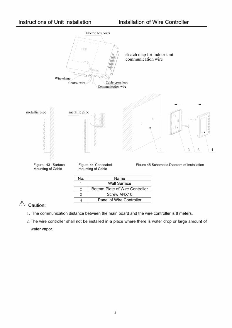
Instructions of Unit Installation Installation of Wire Controller
Electric box cover
Control wireCommunication wire
Cable-cross loopWire clamp
sketch map for indoor unit communication wire
1 32 4
metallic pipe metallic pipe
Figure 43 Surface Mounting of Cable
Figure 44 Concealedmounting of Cable
No. Name 1 Wall Surface 2 Bottom Plate of Wire Co3 Screw M4X10 4 Panel of Wire Contr
Caution:
1. The communication distance between the main board an
2.The wire controller shall not be installed in a place where
water vapor.
38
Figure 45 Schematic Diagram of Installation
ntroller
oller
d the wire controller is 8 meters.
there is water drop or large amount of
39
Instructions of Unit Installation Electrical Installation Caution: Before installing the electrical equipment, please pay attention to the following matters
which have been specially pointed out by our designers: (1) Check to see if the power supply used conforms to the rated power supply specified on the
nameplate. (2) The capacity of the power supply must be large enough. (3) The lines must be installed by professional personnel.
An electricity leakage protection switch and an air switch with gap between electrode heads larger than 3mm shall be installed in the fixed line.
1. Connection of signal wire (1) Use wire stripper to strip the insulation layer (25mm long) from the end of the signal wire. (2) Remove the screw at the terminal board of the air-conditioning unit. (3) Use pliers to bend the end of the signal wire so that a loop matching the screw size is formed. (4) Put the screw through the loop of the signal wire and fix the loop at the terminal board.
2. Connection of multiple twisted wires (1) Use wire stripper to strip the insulation layer (10mm long) from the end of the multiple twisted
wires. (2) Remove the screw at the terminal board of the air-conditioning unit. (3) Use crimping pliers to connect a terminal (matching the size of the screw) at the end of the
multiple twisted wires. (4) Put the screw through the terminal of the multiple twisted wires and fix the terminal at the
terminal board.
Warning: If the power supply flexible line or the signal line of the equipment is damaged, only use special flexible line to replace it. 1. Before connecting lines, read the voltages of the relevant parts on the nameplate. Then carry
out line connection according to the schematic diagram. 2. The air-conditioning unit shall have special power supply line which shall be equipped with
electricity leakage switch and air switch, so as to deal with overload conditions. 3. The air-conditioning unit must have grounding to avoid hazard owing to insulation failure. 4. All fitting lines must use crimp terminals or single wire. If multiple twisted wires are connected
to terminal board, arc may arise. 5. All line connections must conform to the schematic diagram of lines. Wrong connection may
cause abnormal operation or damage of the air-conditioning unit. 6. Do not let any cable contact the refrigerant pipe, the compressor and moving parts such as fan. 7. Do not change the internal line connections inside the air-conditioning unit. The manufacturer
shall not be liable for any loss or abnormal operation arising from wrong line connections. Power Cable Connection: 1. Air-conditioning unit with single-phase power supply (1) Remove the front-side panel of the outdoor unit. (2) Pass the cable though rubber ring. (3) Connect the power supply cable to the “L, N” terminals and
the grounding screw on the metal electric box.
40
Instructions of Unit Installation Electrical Installation
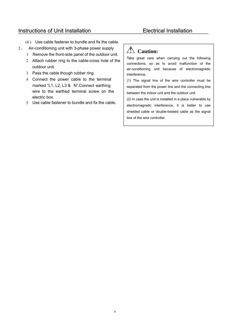
(4 ) Use cable fastener to bundle and fix the cable.
Caution: Take great care when carrying out the followingconnections, so as to avoid malfunction of theair-conditioning unit because of electromagneticinterference.
(1) The signal line of the wire controller must be
separated from the power line and the connecting line
between the indoor unit and the outdoor unit.
(2) In case the unit is installed in a place vulnerable by
electromagnetic interference, it is better to use
shielded cable or double-twisted cable as the signal
line of the wire controller.
2。 Air-conditioning unit with 3-phase power supply 1 Remove the front-side panel of the outdoor unit.
2 Attach rubber ring to the cable-cross hole of the outdoor unit.
3 Pass the cable though rubber ring. 4 Connect the power cable to the terminal
earthing marked “L1, L2, L3 & N”.
5 Use cable fastener to bundle and fix the cable.
Connectwire to the earthed terminal screw on theelectric box.
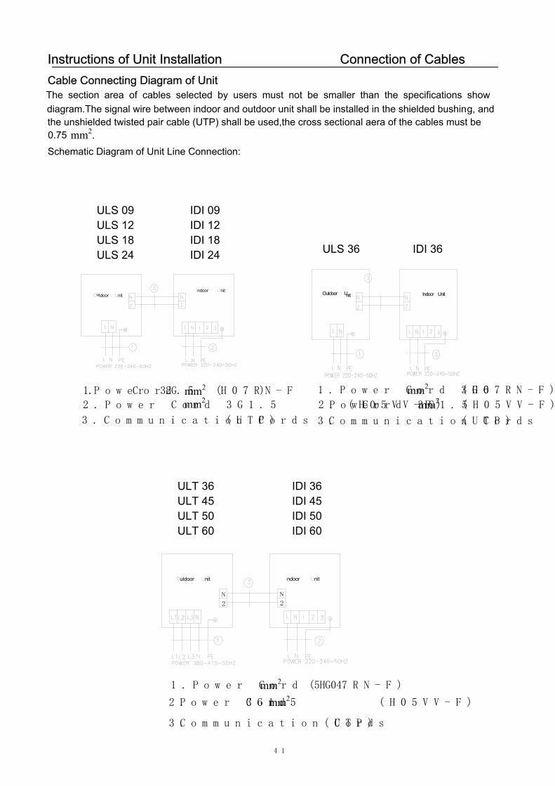
Instructions of Unit Installation Connection of CablesCable Connecting Diagram of Unit
Schematic Diagram of Unit Line Connection:
utdoor nitndoor nit Outdoor Unit Indoor Unit
utdoor nit ndoor nit
N
2
N
2
3.Communication Cords (UTP)
41
The section area of cables selected by users must not be smaller than the specifications show diagram.The signal wire between indoor and outdoor unit shall be installed in the shielded bushing, and the unshielded twisted pair cable (UTP) shall be used,the cross sectional aera of the cables must be
0.75 mm2.
3.Communication Cords (UTP)
3.Communication Cords (UTP)
1.Power Cord 3G2.5 (H07RN-F)mm2 2.Power Cord 3G1.5 (H05VV-F)
1.Power Cord 3G6 (H07RN-F)
2.Power Cord 3G1.5 (H05VV-F)
1.Power Cord 5G4 (H07RN-F)
2.Power Cord 3G1.5 (H05VV-F)
mm2 mm2
mm2
mm2 mm2
ULS 36 IDI 36
ULT 36 IDI 36ULT 45 IDI 45ULT 50 IDI 50ULT 60 IDI 60
ULS 09 IDI 09ULS 12 IDI 12ULS 18 IDI 18ULS 24 IDI 24
42
Instructions of Unit Installation
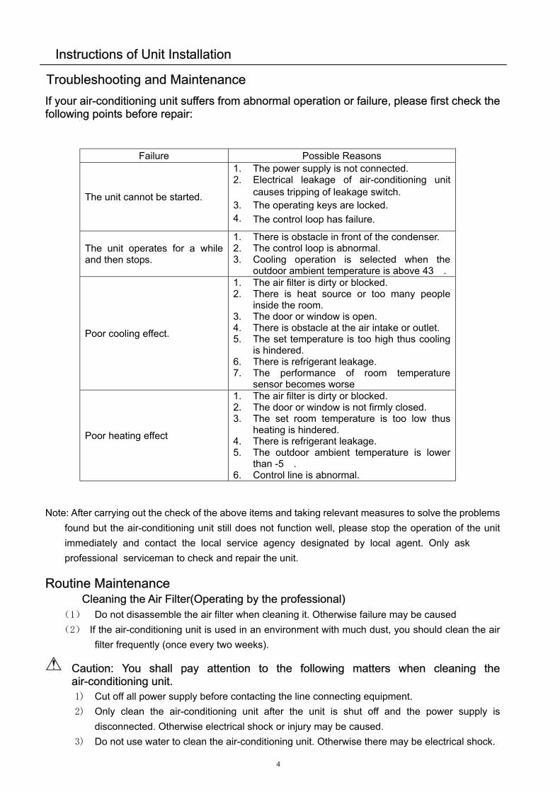
If your air-conditioning unit suffers from abnormal operation or failure, please first check the following points before repair:
Failure Possible Reasons
The unit cannot be started.
1. The power supply is not connected. 2. Electrical leakage of air-conditioning unit
causes tripping of leakage switch. 3. 4.
The operating keys are locked. The control loop has failure.
The unit operates for a while and then stops.
2. The control loop is abnormal. 3. Cooling operation is selected when the
outdoor ambient temperature is above 43℃.
Poor cooling effect.
1. The air filter is dirty or blocked. 2. There is heat source or too many people
inside the room. 3. The door or window is open. 4. There is obstacle at the air intake or outlet. 5. The set temperature is too high thus cooling
is hindered. 6. There is refrigerant leakage. 7. The performance of room temperature
sensor becomes worse
Poor heating effect
1. The air filter is dirty or blocked. 2. The door or window is not firmly closed. 3. The set room temperature is too low thus
heating is hindered. 4. There is refrigerant leakage. 5. The outdoor ambient temperature is lower
than -5℃. 6. Control line is abnormal.
1. There is obstacle in front of the condenser.
Note: After carrying out the check of the above items and taking relevant measures to solve the problems found but the air-conditioning unit still does not function well, please stop the operation of the unit immediately and contact the local service agency designated by local agent. Only askprofessional serviceman to check and repair the unit.
Routine Maintenance Cleaning the Air Filter(Operating by the professional)
(1) Do not disassemble the air filter when cleaning it. Otherwise failure may be caused (2) If the air-conditioning unit is used in an environment with much dust, you should clean the air
filter frequently (once every two weeks).
Caution: You shall pay attention to the following matters when cleaning the air-conditioning unit. 1) Cut off all power supply before contacting the line connecting equipment. 2) Only clean the air-conditioning unit after the unit is shut off and the power supply is
disconnected. Otherwise electrical shock or injury may be caused. 3) Do not use water to clean the air-conditioning unit. Otherwise there may be electrical shock.
Troubleshooting and Maintenance
43
Instructions of Unit Installation Troubleshooting and Maintenance
4) Take care when cleaning the air-conditioning unit. Use a steady stepping stand. 2. Maintenance at the Beginning of Operating Season
Check the air inlet and outlet of the indoor and outdoor units to confirm there is no blockage.Check to see if the grounding wire is in good condition;(Operating by the professional)Check to see if the line connection is in good condition;(Operating by the professional)Check if there is any word displaying on the LCD of the wire controller after connecting the unit to power supply.
Note: If there is any abnormal condition, ask aftersales personnel to offer guidance. 3. Maintenance at the End of the Operational Season
(1) When the weather is clear, operate the unit under fan mode for half a day, so as to dry the inside of the unit.
(2) If not to use the air-conditioning unit for a long time, please cut off the power supply. Now
the words on the LCD of the wire controller shall disappear.
WARNING!
Please seek an authorized repair station for installation work. Improper installation might cause water leakage, electric shock or fire.
Please install at a place strong enough to support the weight of air conditioner unit. If not, the air conditioner unit might fall down and cause human injury or death.
To ensure proper drainage, the drainage pipe shall be correctly installed according to installation instructions. Take proper measures for heat preservation to prevent condensing. Improper installation of pipes might cause leakage and wet the articles in the room.
Do not use or store flammable, explosive, poisonous or other dangerous substances beside the air conditioner. In case of trouble (e.g. burnt smell), please immediately cut off the main power of air conditioner unit. Keep air flow to avoid shortage of oxygen in the room. Never insert your finger or any objects into air outlet and inlet grill. Never plug or unplug the power cable directly to start or stop the air-conditioning unit. Please take constant care to check if the mounting rack is damaged after long use. Never modify the air conditioner. Please contact the dealer or professional installation workers for repair or
relocation of the air conditioner. The appliance shall not be installed in the laundry.
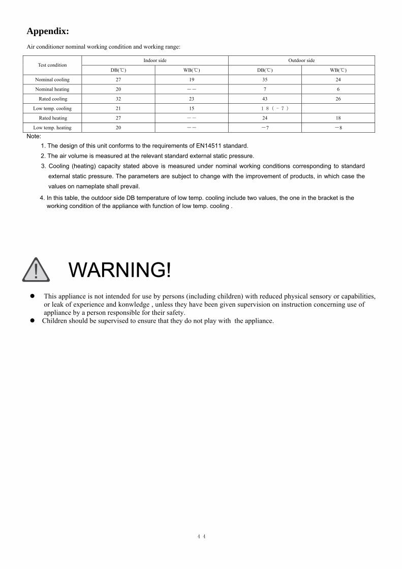
1. The design of this unit conforms to the requirements of EN14511 standard. 2. The air volume is measured at the relevant standard external static pressure. 3. Cooling (heating) capacity stated above is measured under nominal working conditions corresponding to standard
external static pressure. The parameters are subject to change with the improvement of products, in which case the
values on nameplate shall prevail.
Appendix: Air conditioner nominal working condition and working range:
Note:
Indoor side Outdoor side Test condition
DB(℃) WB(℃) DB(℃) WB(℃)
Nominal cooling 27 19 35 24
Nominal heating 20 ―― 7 6
Rated cooling 32 23 43 26
Low temp. cooling 21 15 18(-7) ――
Rated heating 27 ―― 24 18
Low temp. heating 20 ―― -7 -8
WARNING!
This appliance is not intended for use by persons (including children) with reduced physical sensory or capabilities, or leak of experience and konwledge , unless they have been given supervision on instruction concerning use of appliance by a person responsible for their safety.
Children should be supervised to ensure that they do not play with the appliance.
4. In this table, the outdoor side DB temperature of low temp. cooling include two values, the one in the bracket is the working condition of the appliance with function of low temp. cooling .
44
