introductory module technical guidance document
TRANSCRIPT
Introductory ModuleTechnical Guidance Document
New Development and Significant Redevelopment Program Roll-out Training
July 2011
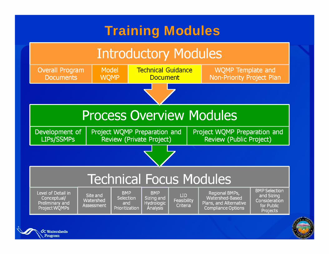
Training Modules
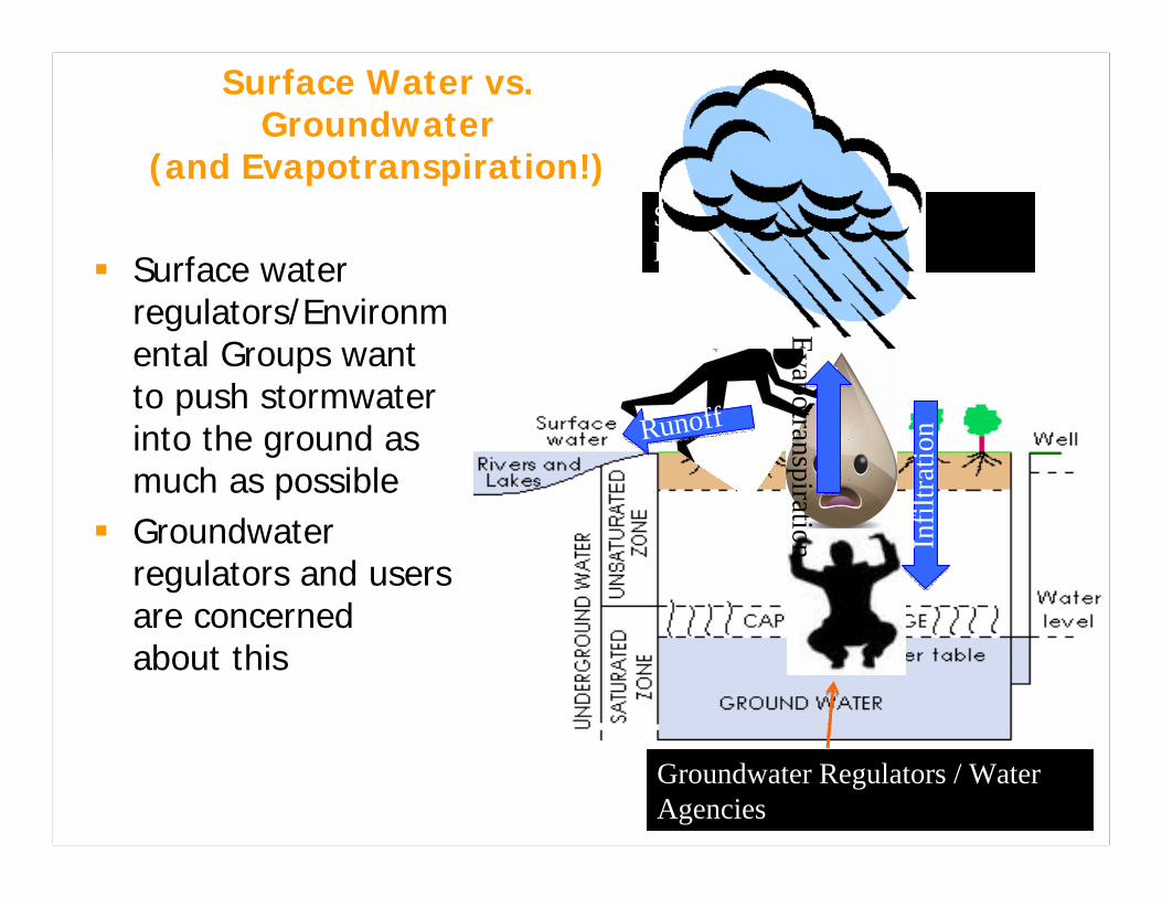
Surface Water vs. Groundwater
(and Evapotranspiration!)3
Surface water regulators/Environmental Groups want to push stormwater into the ground as much as possibleGroundwater regulators and users are concerned about this
Surface Water Regulators/NRDC
Groundwater Regulators / Water Agencies
Runoff
Infil
tratio
n
Evapotranspiration
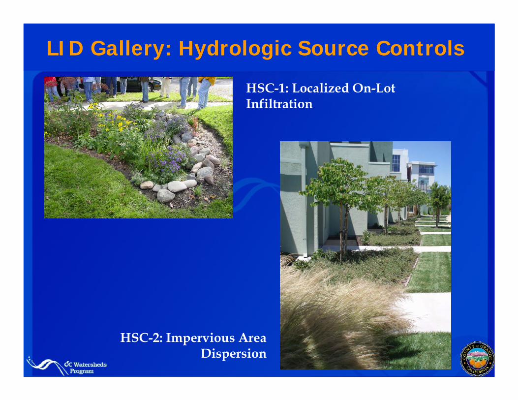
LID Gallery: Hydrologic Source Controls
HSC-1: Localized On-Lot Infiltration
HSC-2: Impervious Area Dispersion
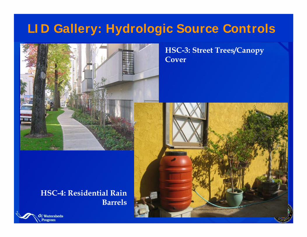
LID Gallery: Hydrologic Source Controls
HSC-3: Street Trees/Canopy Cover
HSC-4: Residential Rain Barrels
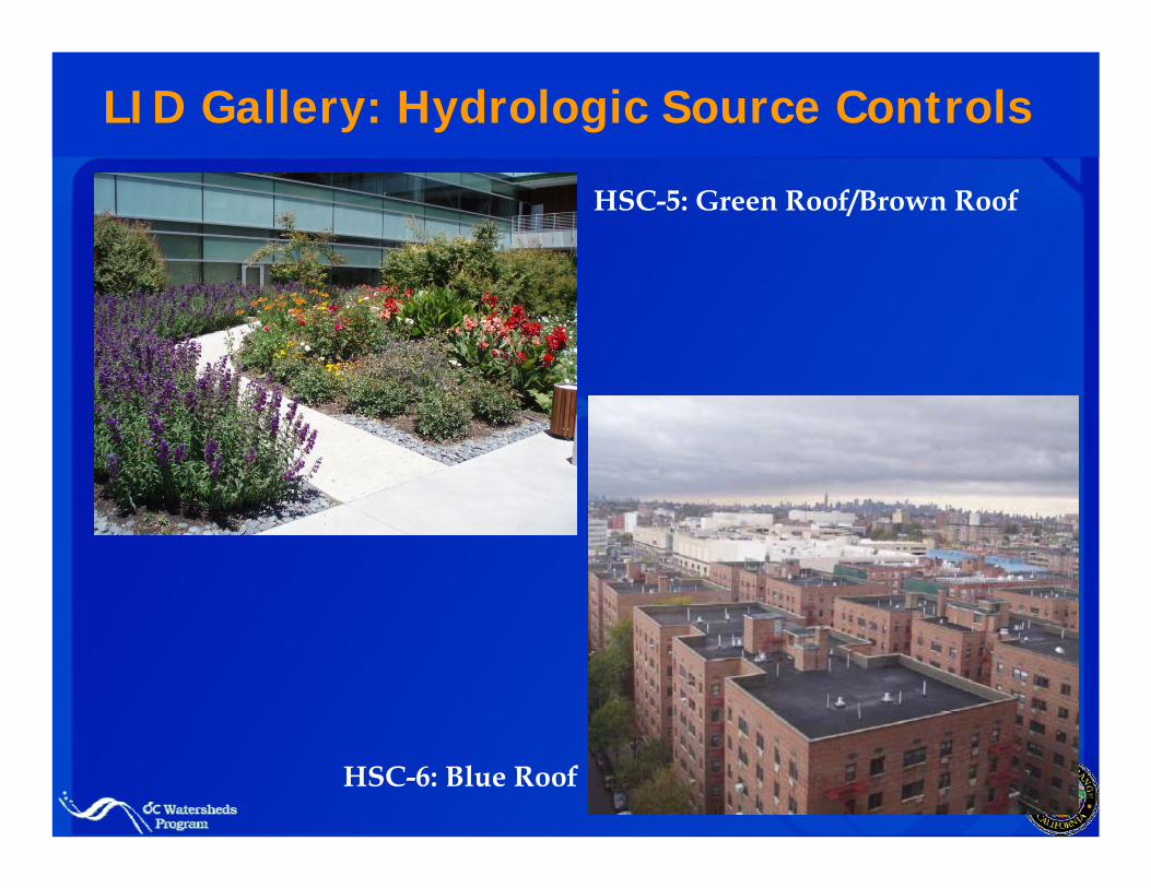
LID Gallery: Hydrologic Source Controls
HSC-5: Green Roof/Brown Roof
HSC-6: Blue Roof
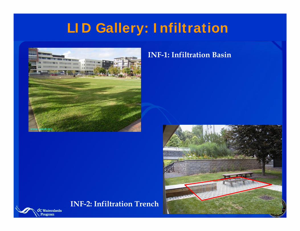
LID Gallery: Infiltration
INF-1: Infiltration Basin
INF-2: Infiltration Trench
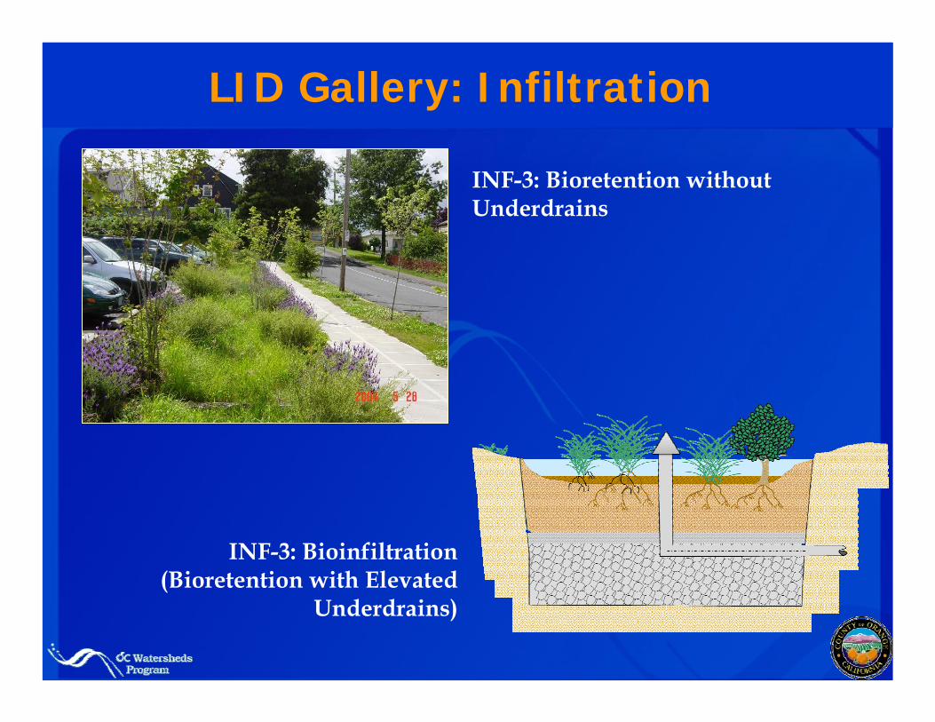
LID Gallery: Infiltration
INF-3: Bioretention without Underdrains
INF-3: Bioinfiltration (Bioretention with Elevated
Underdrains)
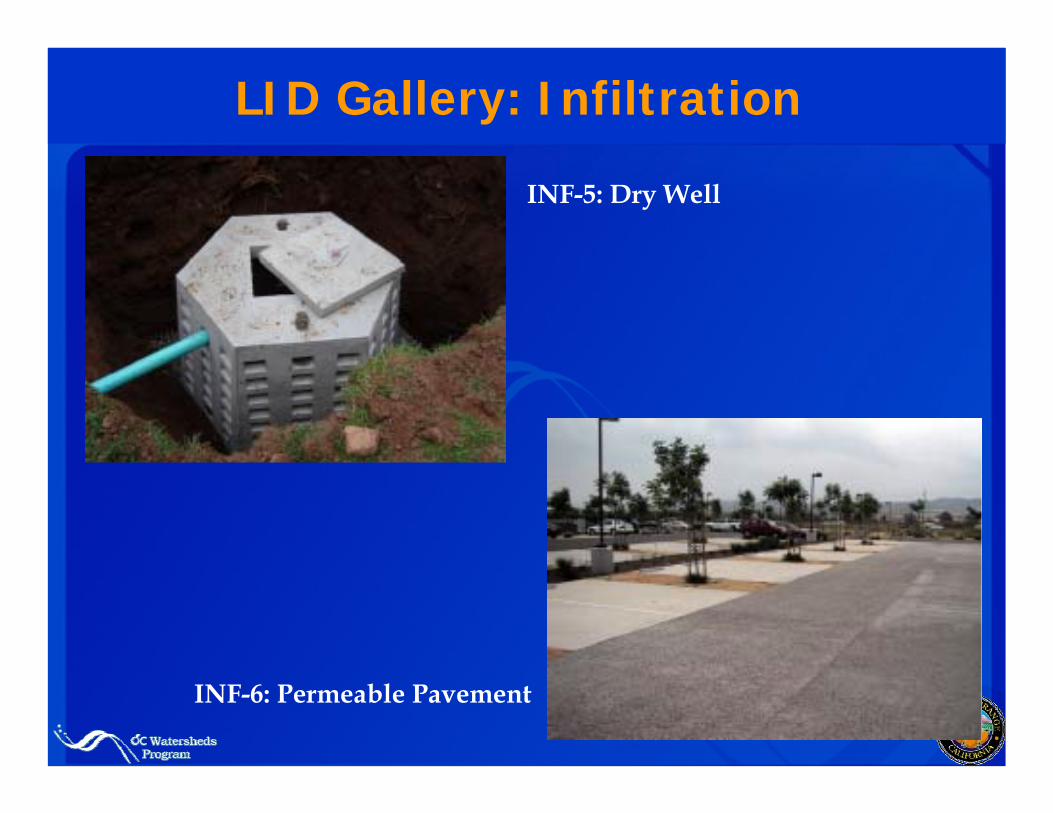
LID Gallery: Infiltration
INF-5: Dry Well
INF-6: Permeable Pavement
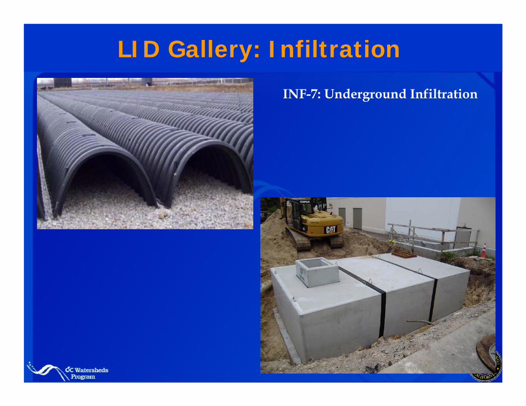
LID Gallery: Infiltration
INF-7: Underground Infiltration
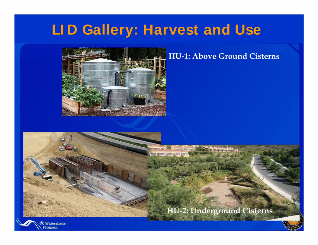
LID Gallery: Harvest and Use
HU-1: Above Ground Cisterns
HU-2: Underground Cisterns
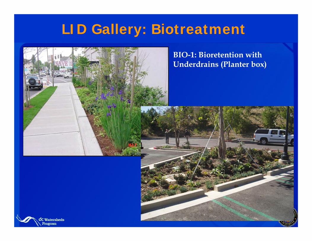
LID Gallery: Biotreatment
BIO-1: Bioretention with Underdrains (Planter box)
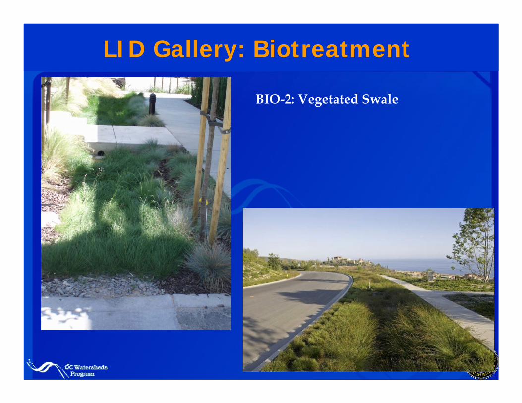
LID Gallery: Biotreatment
BIO-2: Vegetated Swale
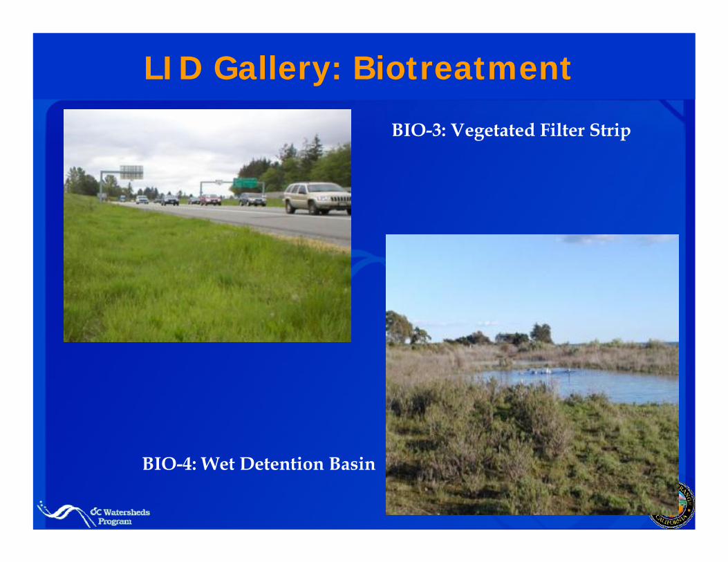
LID Gallery: Biotreatment
BIO-3: Vegetated Filter Strip
BIO-4: Wet Detention Basin
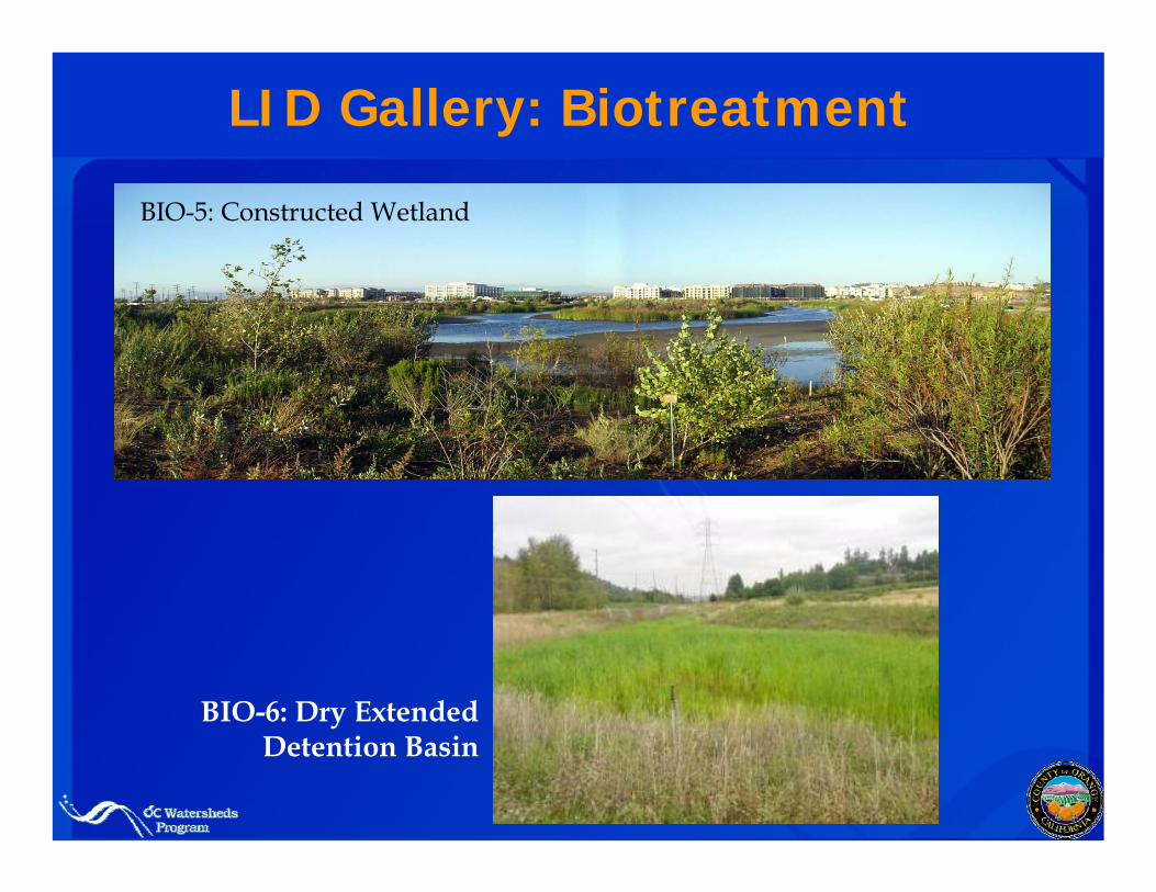
LID Gallery: Biotreatment
BIO-6: Dry Extended Detention Basin
BIO-5: Constructed Wetland
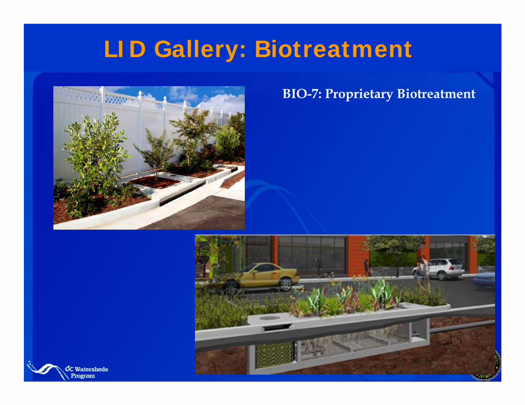
LID Gallery: Biotreatment
BIO-7: Proprietary Biotreatment
Purpose of TGD
Provide technical guidance for developing Project WQMPs
Assist in practical, objective interpretation of permit-based requirements
Provide recommended processes for developing plans and demonstrating conformance
Provide technically-based feasibility criteria
Provide supporting information for BMP selection, analysis, and design
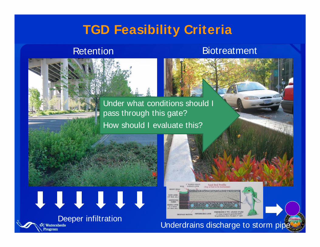
TGD Feasibility Criteria
Deeper infiltrationUnderdrains discharge to storm pipe
Retention Biotreatment
Under what conditions should I pass through this gate? How should I evaluate this?
TGD Preparation Challenges
The TGD needs to:
Provide rigorous technical defense for criteria
Attempt to accommodate all foreseeable project scenarios
Bridge separate requirements in NOC and SOC permit areas
But it needs to be usable!
TGD Approach
Focus intensive guidance on several common project scenarios
Locate supporting technical material in appendicesExamples: groundwater protection criteria, BMP sizing calculation methods
Try to distill feasibility criteria to simple tables and thresholds where possible (example: TUTIA)
Break out separate appendices for NOC and SOC permit areas
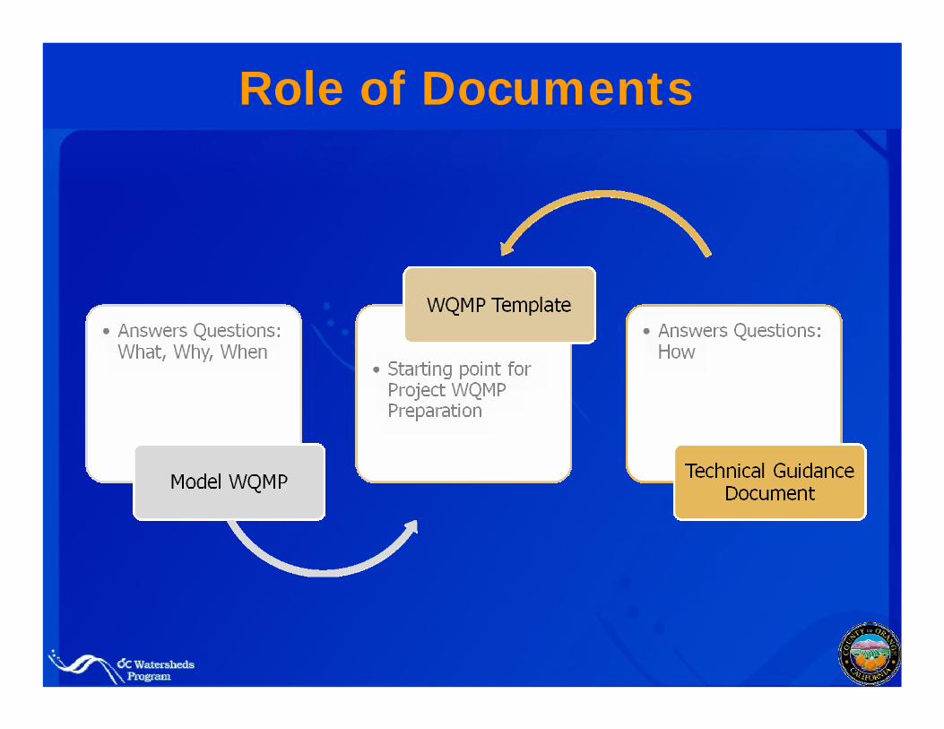
Role of Documents
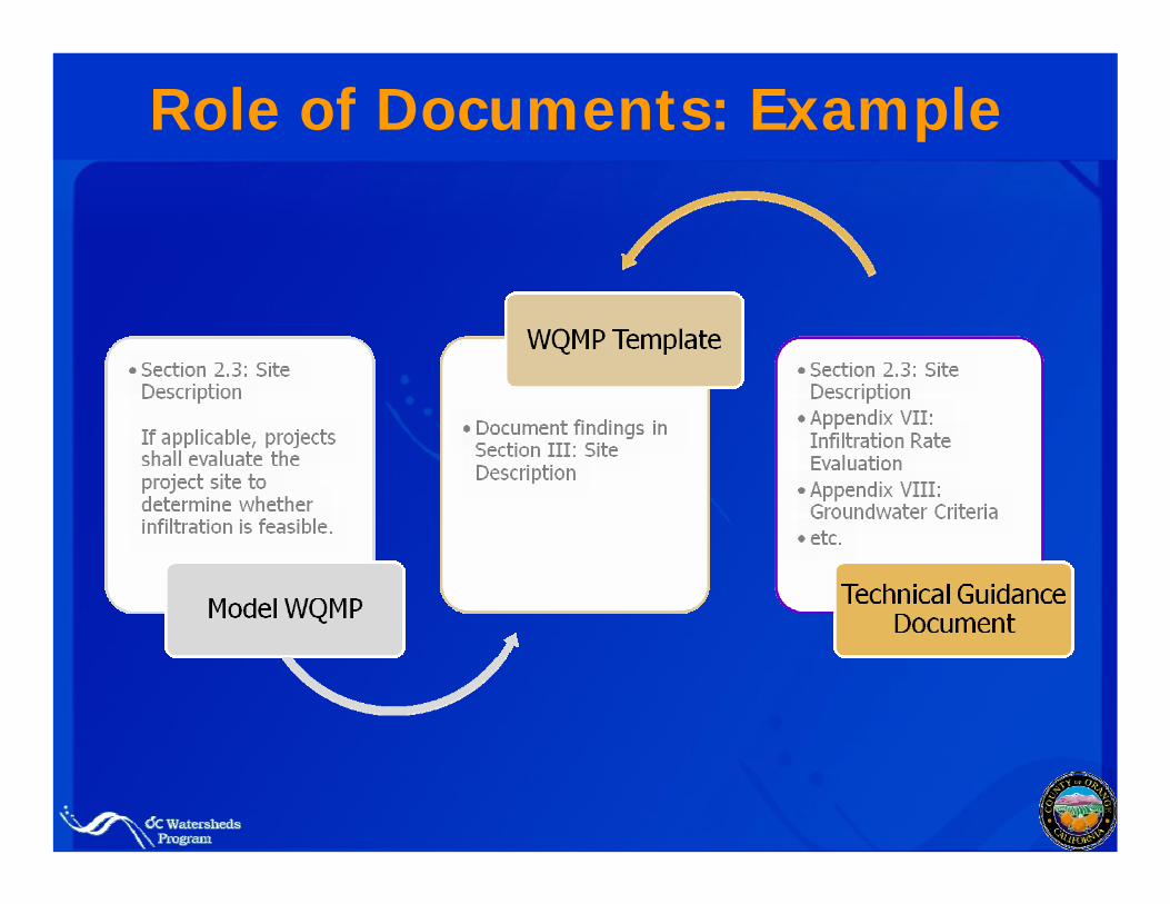
Role of Documents: Example
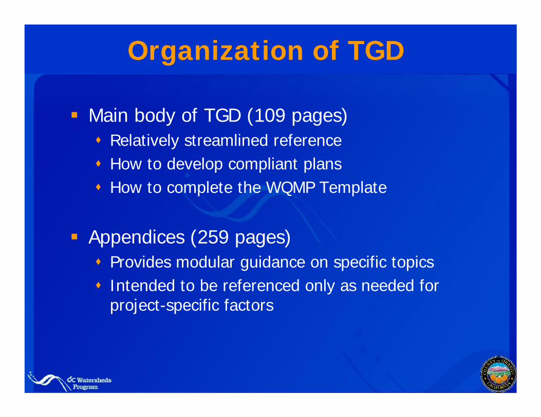
Organization of TGD
Main body of TGD (109 pages)Relatively streamlined reference How to develop compliant plans How to complete the WQMP Template
Appendices (259 pages)Provides modular guidance on specific topicsIntended to be referenced only as needed for project-specific factors
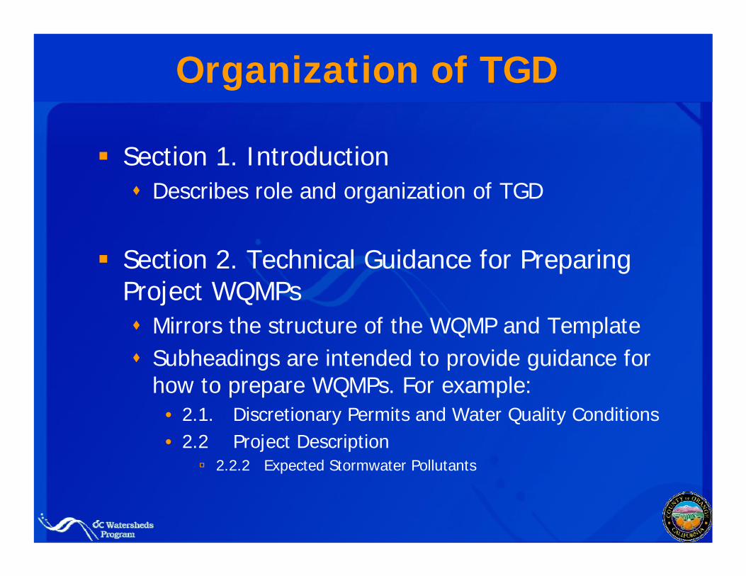
Organization of TGD
Section 1. IntroductionDescribes role and organization of TGD
Section 2. Technical Guidance for Preparing Project WQMPs
Mirrors the structure of the WQMP and Template Subheadings are intended to provide guidance for how to prepare WQMPs. For example:
• 2.1. Discretionary Permits and Water Quality Conditions• 2.2 Project Description
2.2.2 Expected Stormwater Pollutants
Key highlights of TGD Section 2
Site and watershed characterization
BMP selection flowchart
Feasibility criteria and worksheet
Guidance on demonstrating conformance with BMP sizing and selection requirements for a variety of common scenarios
Guidance on incorporating USEPA Green Streets into WQMPs
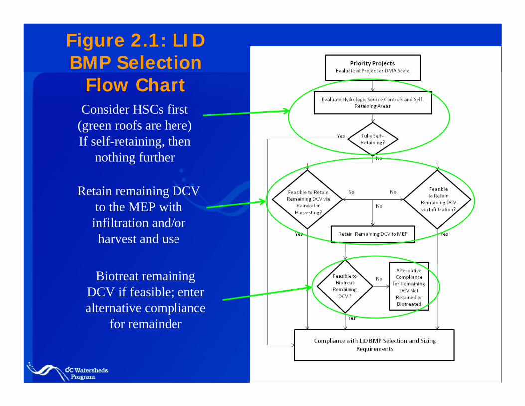
Figure 2.1: LID BMP Selection
Flow ChartConsider HSCs first
(green roofs are here)If self-retaining, then
nothing further
Retain remaining DCV to the MEP with infiltration and/or harvest and use
Biotreat remaining DCV if feasible; enter alternative compliance
for remainder
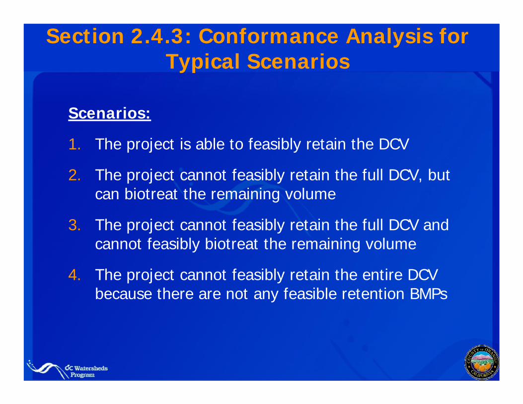
Section 2.4.3: Conformance Analysis for Typical Scenarios
Scenarios:
1. The project is able to feasibly retain the DCV
2. The project cannot feasibly retain the full DCV, but can biotreat the remaining volume
3. The project cannot feasibly retain the full DCV and cannot feasibly biotreat the remaining volume
4. The project cannot feasibly retain the entire DCV because there are not any feasible retention BMPs
Organization of TGD
Section 3. Site Design Principles and Techniques
Narrative elements of LID related to site layout and planningMinimal overlap with Section 4
Section 4. LID and Treatment Control BMP Design
Inventory of LID and Treatment Control BMPsSelecting BMPs to address pollutants of concernBMP Performance Tables
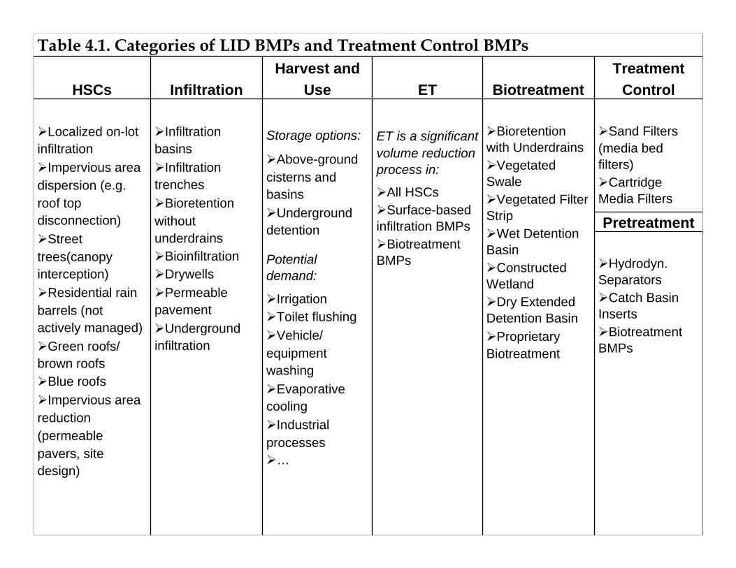
Table 4.1. Categories of LID BMPs and Treatment Control BMPs
HSCs InfiltrationHarvest and
Use ET BiotreatmentTreatment
Control
Localized on-lot infiltration
Impervious area dispersion (e.g. roof top disconnection)
Street trees(canopy interception)
Residential rain barrels (not actively managed)
Green roofs/ brown roofs
Blue roofsImpervious area
reduction (permeable pavers, site design)
Infiltration basins
Infiltration trenches
Bioretention without underdrains
BioinfiltrationDrywellsPermeable
pavementUnderground
infiltration
Storage options:
Above-ground cisterns and basins
Underground detention
Potential demand:
IrrigationToilet flushingVehicle/
equipment washing
Evaporative cooling
Industrial processes
…
ET is a significant volume reduction process in:
All HSCsSurface-based
infiltration BMPsBiotreatment
BMPs
Bioretention with Underdrains
Vegetated Swale
Vegetated Filter Strip
Wet Detention Basin
Constructed Wetland
Dry Extended Detention Basin
Proprietary Biotreatment
Sand Filters (media bed filters)
Cartridge Media Filters
Pretreatment
Hydrodyn. Separators
Catch Basin Inserts
Biotreatment BMPs
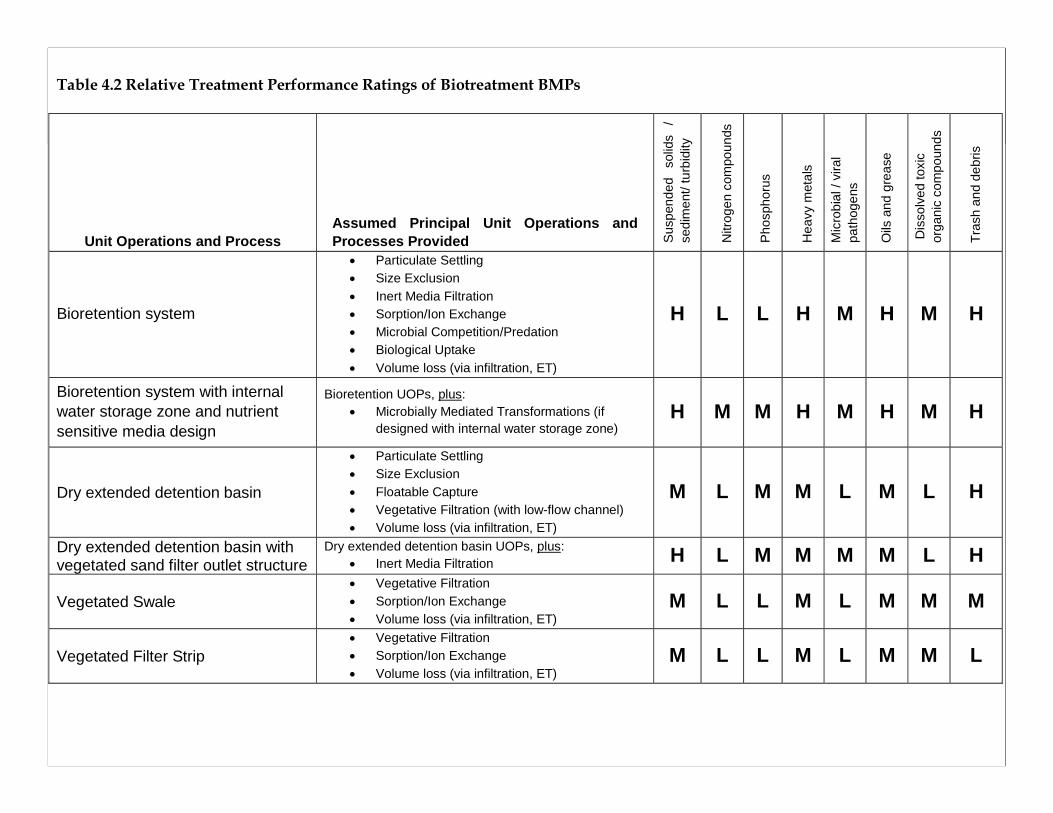
Table 4.2 Relative Treatment Performance Ratings of Biotreatment BMPs
Unit Operations and Process Assumed Principal Unit Operations and Processes Provided S
uspe
nded
so
lids
/ se
dim
ent/
turb
idity
Nitr
ogen
com
poun
ds
Pho
spho
rus
Hea
vy m
etal
s
Mic
robi
al /
vira
l pa
thog
ens
Oils
and
gre
ase
Dis
solv
ed to
xic
orga
nic
com
poun
ds
Tras
h an
d de
bris
Bioretention system
• Particulate Settling • Size Exclusion • Inert Media Filtration • Sorption/Ion Exchange • Microbial Competition/Predation • Biological Uptake • Volume loss (via infiltration, ET)
H L L H M H M H
Bioretention system with internal water storage zone and nutrient sensitive media design
Bioretention UOPs, plus: • Microbially Mediated Transformations (if
designed with internal water storage zone) H M M H M H M H
Dry extended detention basin
• Particulate Settling • Size Exclusion • Floatable Capture • Vegetative Filtration (with low-flow channel) • Volume loss (via infiltration, ET)
M L M M L M L H
Dry extended detention basin with vegetated sand filter outlet structure
Dry extended detention basin UOPs, plus: • Inert Media Filtration H L M M M M L H
Vegetated Swale • Vegetative Filtration • Sorption/Ion Exchange • Volume loss (via infiltration, ET)
M L L M L M M M
Vegetated Filter Strip • Vegetative Filtration • Sorption/Ion Exchange • Volume loss (via infiltration, ET)
M L L M L M M L
Organization of TGD
Section 5. Hydromodification Control DesignHydromodification design conceptsDescription of hydromodification controlsDesign process for NOC and SOC
Section 6. Source Control MeasuresStructuralNon-structuralMunicipal
Organization of TGD
Section 7. Operations and Maintenance Planning
Developing maintenance agreementsDeveloping BMP maintenance activities
Contents and Roles of Appendices
Appendix I. Summary of BMP Sizing Requirements for North Orange County
Describes role of various BMPs Condensed guidance on selection and sizing for various project scenariosPlain-language “cheat sheet”
Appendix II. Summary of BMP Sizing Requirements for South Orange County
Same role and contents as Appendix I
Contents and Roles of Appendices
Appendix III. Hydrologic Calculations and Sizing Methods For LID BMPs
Describes various methods for calculating the Design Capture Volume (DCV)Includes worksheets and examplesProvides guidance for sizing of BMPs in seriesDescribes basis for percent capture criterion
More info on Appendix III will be provided in the Technical Focus Modules
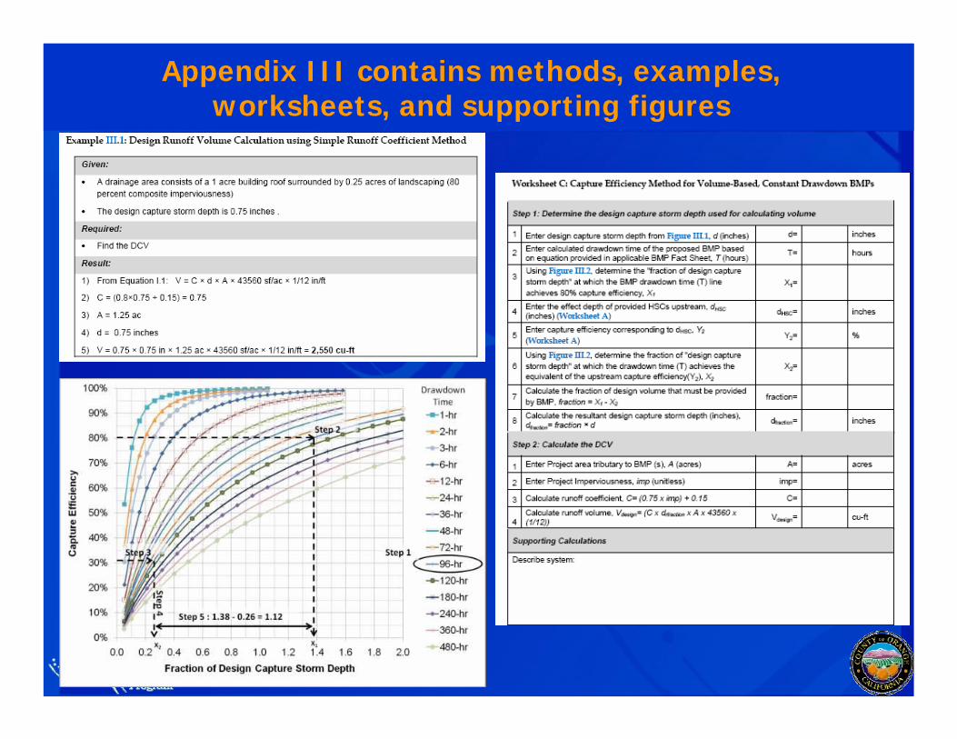
Appendix III contains methods, examples, worksheets, and supporting figures
Contents and Roles of Appendices
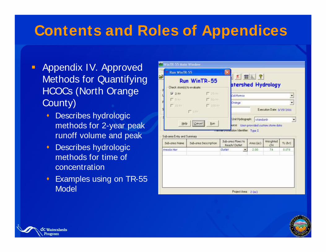
Appendix IV. Approved Methods for Quantifying HCOCs (North Orange County)
Describes hydrologic methods for 2-year peak runoff volume and peakDescribes hydrologic methods for time of concentrationExamples using on TR-55 Model
Contents and Roles of Appendices
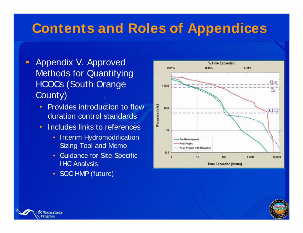
Appendix V. Approved Methods for Quantifying HCOCs (South Orange County)
Provides introduction to flow duration control standards Includes links to references
• Interim Hydromodification Sizing Tool and Memo
• Guidance for Site-Specific IHC Analysis
• SOC HMP (future)
Contents and Roles of Appendices
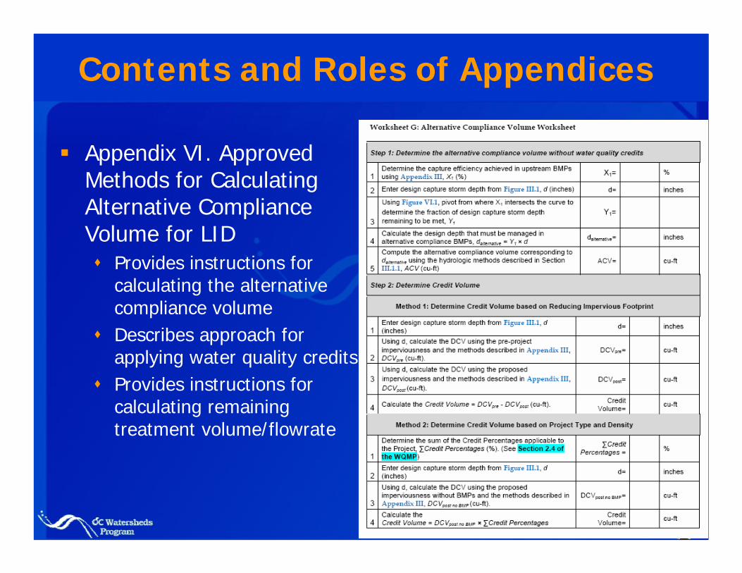
Appendix VI. Approved Methods for Calculating Alternative Compliance Volume for LID
Provides instructions for calculating the alternative compliance volumeDescribes approach for applying water quality creditsProvides instructions for calculating remaining treatment volume/flowrate

Contents and Roles of Appendices
Appendix VII. Infiltration Rate Evaluation Protocol and Factor of Safety Recommendations
Introduces the different roles of infiltration rate evaluationDescribes various methods for evaluating infiltration rateProvides guidance on selecting a factor of safetyMethods coordinated with Riverside County BMP Manual
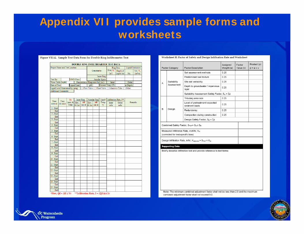
Appendix VII provides sample forms and worksheets
Contents and Roles of Appendices
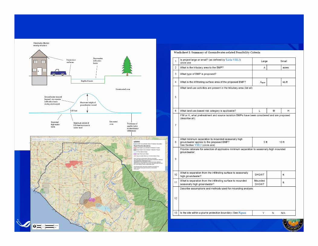
Appendix VIII. Groundwater-related Infiltration Feasibility Criteria
Provides guidance on:• Depth to groundwater and mounding potential• Presence of groundwater plumes• Wellhead protection and septic systems• Contamination risks from land use activities• Consultation with applicable groundwater agencies
Includes technical requirements for conducting site specific studiesDeveloped in coordination with OCWD
Contents and Roles of Appendices
Appendix IX. Technical Basis for Green Roof Design Criteria
Provides criteria to assist in design, review, and approval of green roofs
Appendix X. Harvest and Use Demand Calculations and Feasibility Screening
Provides guidance for computing harvested water demandIncludes pre-computed thresholds for feasibility screening based on project characteristics
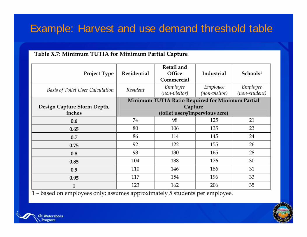
Example: Harvest and use demand threshold table
Table X.7: Minimum TUTIA for Minimum Partial Capture
Project Type Residential Retail and
Office Commercial
Industrial Schools1
Basis of Toilet User Calculation Resident Employee (non-visitor)
Employee (non-visitor)
Employee (non-student)
Design Capture Storm Depth, inches
Minimum TUTIA Ratio Required for Minimum Partial Capture
(toilet users/impervious acre) 0.6 74 98 125 21
0.65 80 106 135 23
0.7 86 114 145 24
0.75 92 122 155 26
0.8 98 130 165 28
0.85 104 138 176 30
0.9 110 146 186 31
0.95 117 154 196 33
1 123 162 206 35 1 – based on employees only; assumes approximately 5 students per employee.
Contents and Roles of Appendices
Appendix XI. Criteria for Designing BMPs to Achieve Maximum Feasible Retention and Biotreatment
“If it is not feasible to retain the entire DCV, what is the maximum portion that is feasible?”
Describes biotreatment design elements to achieve maximum feasible incidental infiltration and ET
Provides recommended percent of site to dedicate to BMPs
Provides objective criteria to support plan development and review
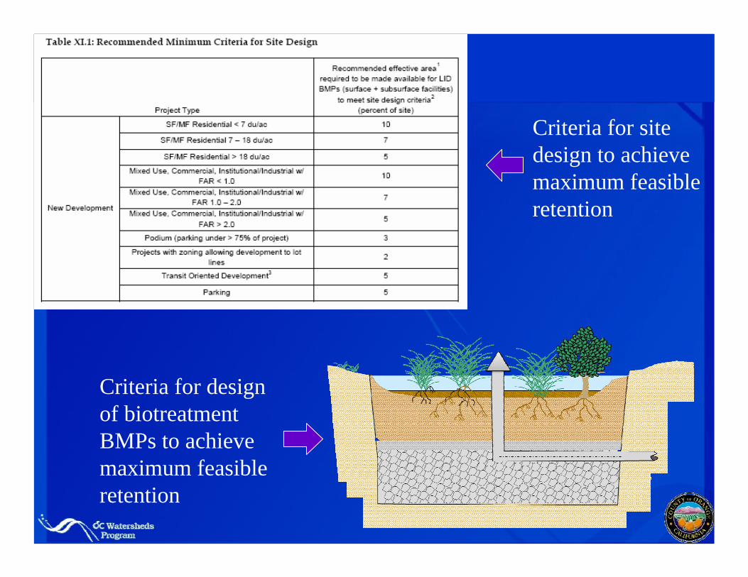
Criteria for site design to achieve maximum feasible retention
Criteria for design of biotreatment BMPs to achieve maximum feasible retention
Contents and Roles of Appendices
Appendix XII. Conceptual Biotreatment Selection, Design, and Maintenance Criteria
Provides lists of criteria that differentiate biotreatment BMPs from conventional treatment controlsIntended to be used to check detailed designs
Appendix XIII. Threshold Incremental Benefit Criterion
Describes conditions under which a well-designed biotreatment BMP would be considered equivalent to retention BMPs
Contents and Roles of Appendices
Appendix XIV. BMP Fact SheetsEach fact sheet:
• Lists OC-specific design criteria• Describes approach for sizing and design (refers to
applicable sections of Appendix III)• Provides references to detailed design manuals
Appendix XV. WorksheetsIncludes a list of worksheets with hot links to the locations of the worksheets in the document
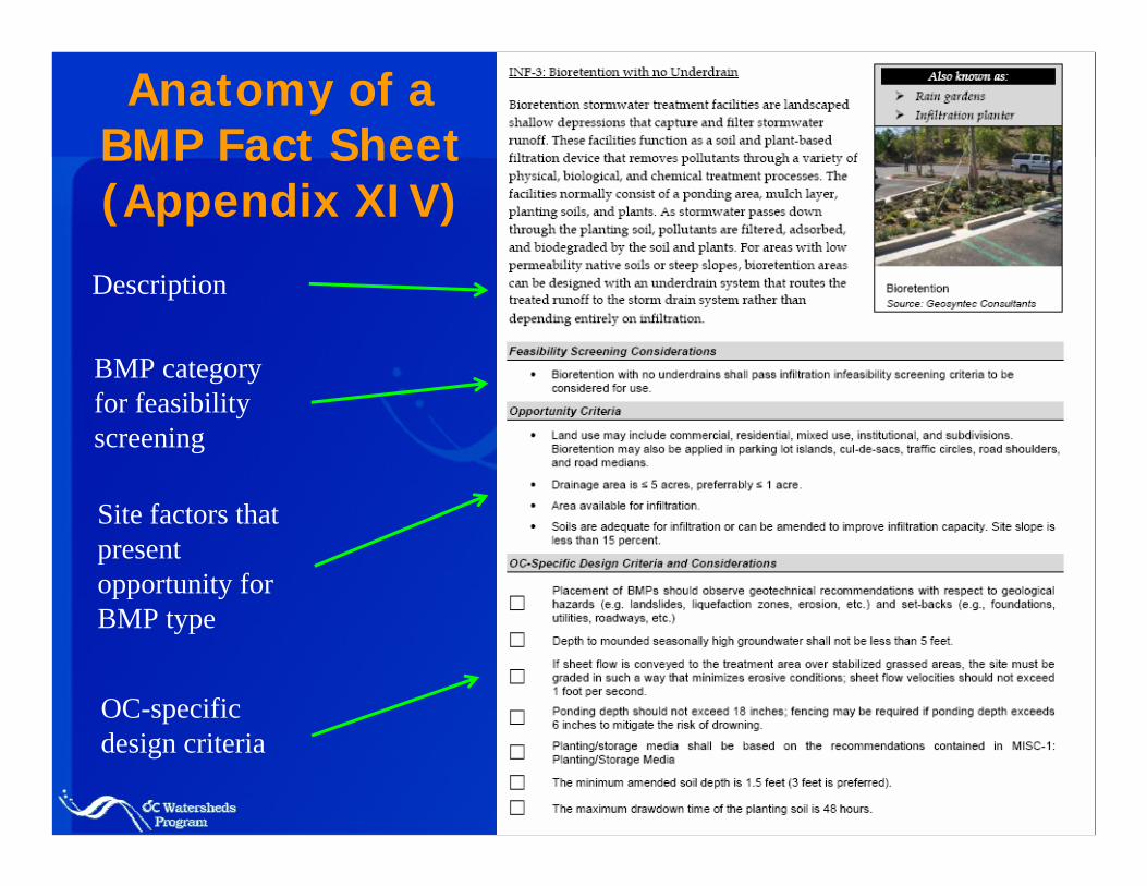
Anatomy of a BMP Fact Sheet (Appendix XIV)
Description
BMP category for feasibility screening
Site factors that present opportunity for BMP type
OC-specific design criteria
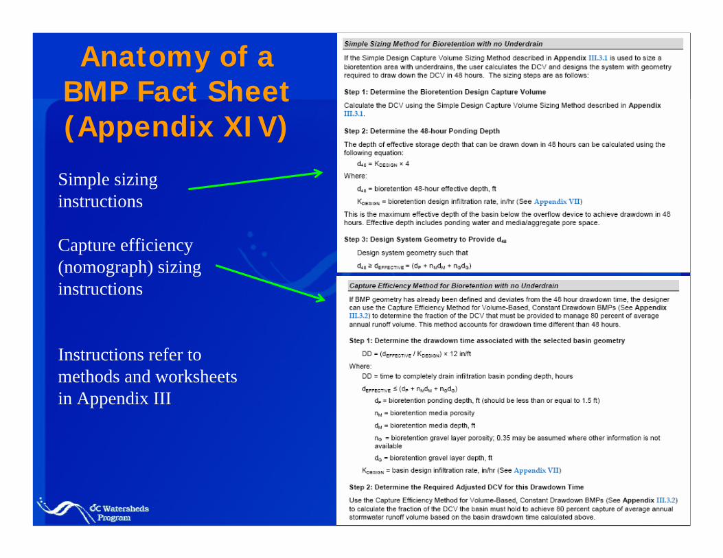
Anatomy of a BMP Fact Sheet (Appendix XIV)
Simple sizing instructions
Capture efficiency (nomograph) sizing instructions
Instructions refer to methods and worksheets in Appendix III
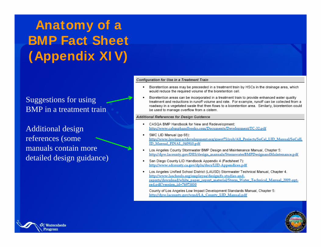
Anatomy of a BMP Fact Sheet (Appendix XIV)
Suggestions for using BMP in a treatment train
Additional design references (some manuals contain more detailed design guidance)
Contents and Roles of Appendices
Appendix XVI. ExhibitsRainfall zonesInfiltration feasibility constraintsNOC Hydromodification Susceptibility Maps
Appendix XVII. Sanitary Sewer I&IPlaceholder for potential appendix to be developed
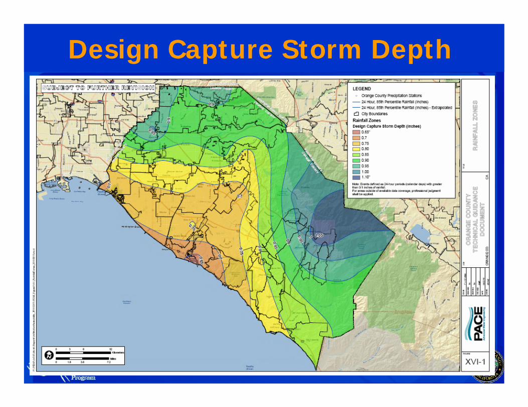
Design Capture Storm Depth
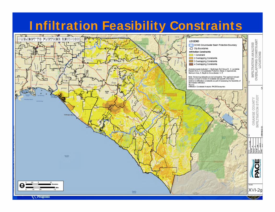
Infiltration Feasibility Constraints
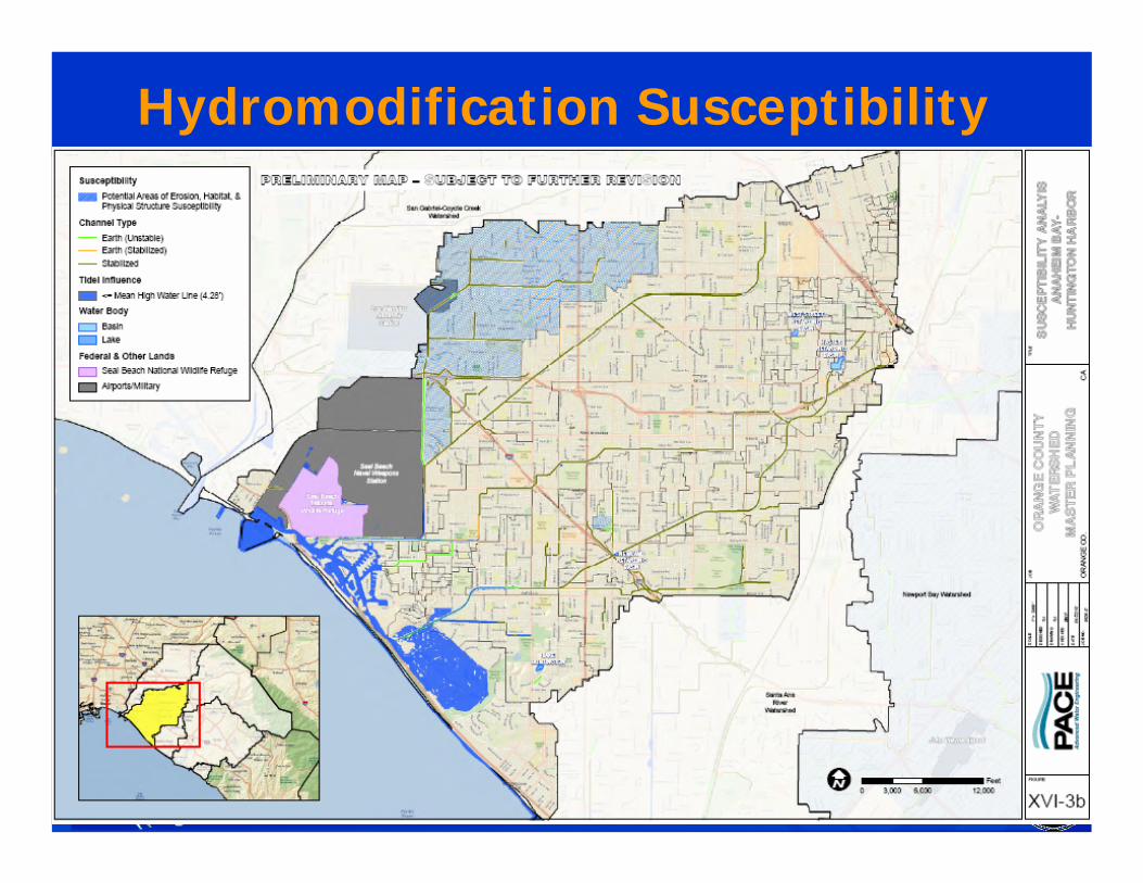
Hydromodification Susceptibility
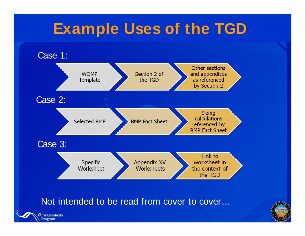
Example Uses of the TGD
Not intended to be read from cover to cover…
Case 1:
Case 2:
Case 3:

Questions