introduction:wood properties,species...
TRANSCRIPT
1
c h a p t e r o n e
INTRODUCTION: WOOD
PROPERTIES , SPECIES , AND GRADES
1.1 INTRODUCTION
The purpose of this book is to present the design process for wood structures in a quick andsimple way, yet thoroughly enough to cover the analysis and design of the major structuralelements. In general, building plans and details are defined by an architect and are usually givento a structural engineer for design of structural elements and to present the design in the formof structural drawings. In this book we take a project-based approach covering the design processthat a structural engineer would go through for a typical wood-framed structure.
The intended audience for this book is students taking a course in timber or structural wooddesign and structural engineers and similarly qualified designers of wood or timber structureslooking for a simple and practical guide for design. The reader should have a working knowledgeof statics, strength of materials, structural analysis (including truss analysis), and load calculationsin accordance with building codes (dead, live, snow, wind, and seismic loads). Design loads arereviewed in Chapter 2. The reader must also have available:
1. National Design Specification for Wood Construction, 2005 edition, ANSI/AF&PA (hereafterreferred to as the NDS code) [1]
2. National Design Specification Supplement: Design Values for Wood Construction, 2005 edition,ANSI/AF&PA (hereafter referred to as NDS-S) [2]
3. International Building Code, 2006 edition, International Code Council (ICC) (hereafter re-ferred to as the IBC) [3]
4. Minimum Design Loads for Buildings and Other Structures, 2005 edition, American Society ofCivil Engineers (ASCE) (hereafter referred to as ASCE 7) [4]
The Project-based Approach
Wood is nature’s most abundant renewable building material and a widely used structural materialin the United States, where more than 80% of all buildings are of wood construction. Thenumber of building configurations and design examples that could be presented is unlimited.Some applications of wood in construction include residential buildings, strip malls, offices,hotels, schools and colleges, healthcare and recreation facilities, senior living and retirementhomes, and religious buildings. The most common wood structures are residential and multi-family dwellings as well as hotels. Residential structures are usually one to three stories in height,while multifamily and hotel structures can be up to four stories in height. Commercial, industrial,and other structures that have higher occupancy loads and factors of safety are not typicallyconstructed with wood, although wood may be used as a secondary structure, such as a storagemezzanine. The structures that support amusement park rides are mostly built out of woodbecause of the relatively low maintenance cost of exposed wood structures and its unique abilityto resist the repeated cycles of dynamic loading (fatigue) imposed on the structure by the amuse-
COPYRIG
HTED M
ATERIAL
2 � S T R U C T U R A L W O O D D E S I G N
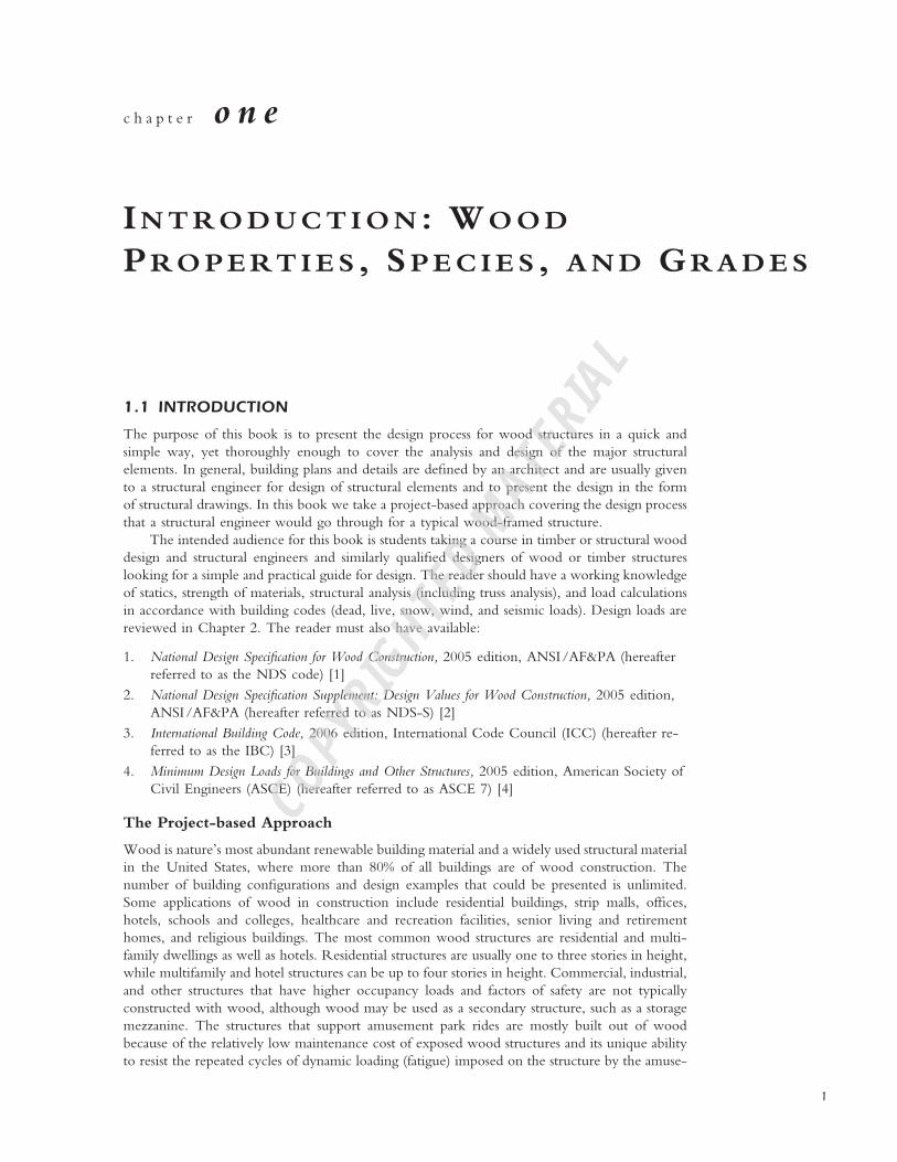
FIGURE 1.1 Perspective overview of a building section.
ment park rides. The approach taken here is a simplified version of the design process requiredfor each major structural element in a timber structure. In Figures 1.1 and 1.2 we identify thetypical structural elements in a wood building. The elements are described in greater detail inthe next section.
1.2 TYPICAL STRUCTURAL COMPONENTS OF WOOD BUILDINGS
The majority of wood buildings in the United States are typically platform construction, in whichthe vertical wall studs are built one story at a time and the floor below provides the platform tobuild the next level of wall that will in turn support the floor above. The walls usually spanvertically between the sole or sill plates at a floor level and the top plates at the floor or rooflevel above. This is in contrast to the infrequently used balloon-type construction, where the vertical
I N T R O D U C T I O N : W O O D P R O P E R T I E S , S P E C I E S , A N D G R A D E S � 3
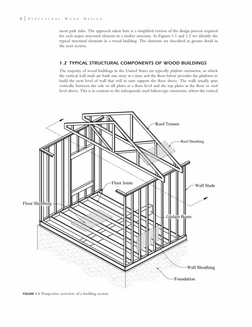
FIGURE 1.2 Overviewof major structuralelements.
studs are continuous for the entire height of the building and the floor framing is supported onbrackets off the face of the wall studs. The typical structural elements in a wood-framed buildingsystem are described below.
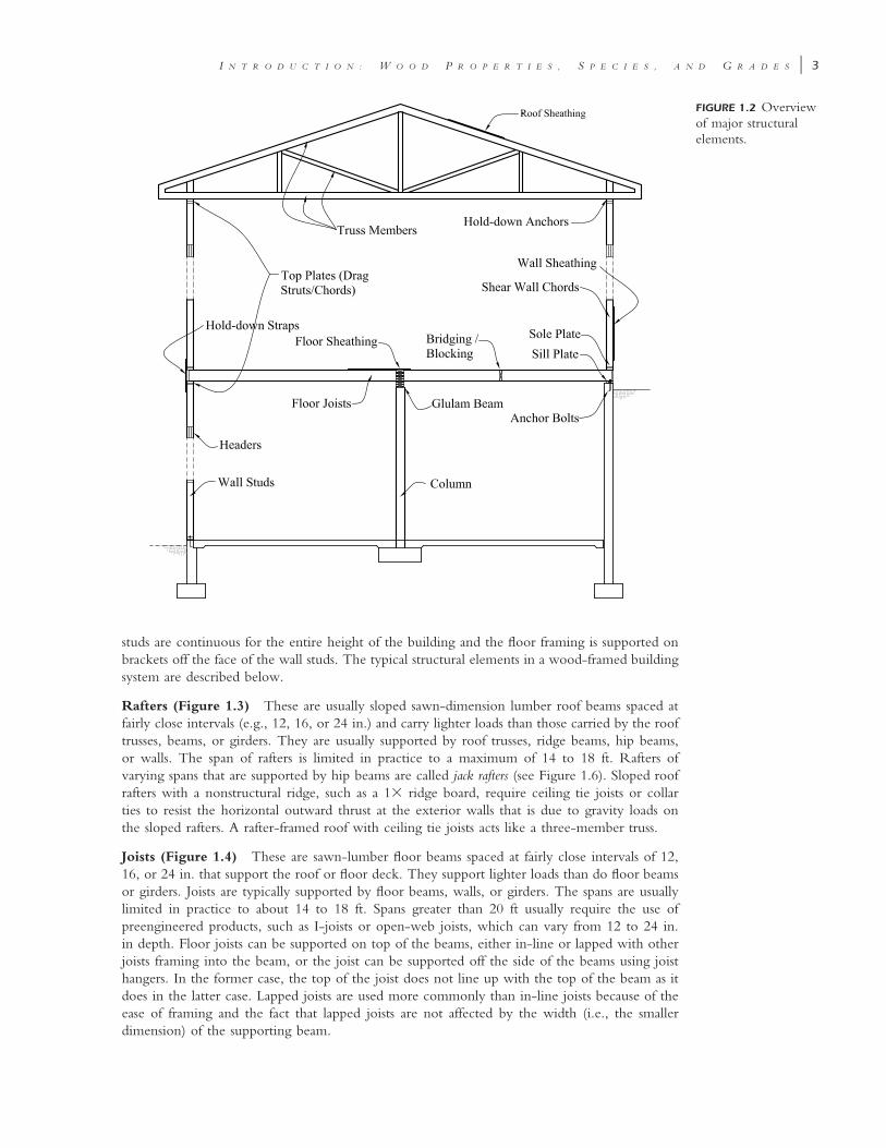
Rafters (Figure 1.3) These are usually sloped sawn-dimension lumber roof beams spaced atfairly close intervals (e.g., 12, 16, or 24 in.) and carry lighter loads than those carried by the rooftrusses, beams, or girders. They are usually supported by roof trusses, ridge beams, hip beams,or walls. The span of rafters is limited in practice to a maximum of 14 to 18 ft. Rafters ofvarying spans that are supported by hip beams are called jack rafters (see Figure 1.6). Sloped roofrafters with a nonstructural ridge, such as a 1� ridge board, require ceiling tie joists or collarties to resist the horizontal outward thrust at the exterior walls that is due to gravity loads onthe sloped rafters. A rafter-framed roof with ceiling tie joists acts like a three-member truss.
Joists (Figure 1.4) These are sawn-lumber floor beams spaced at fairly close intervals of 12,16, or 24 in. that support the roof or floor deck. They support lighter loads than do floor beamsor girders. Joists are typically supported by floor beams, walls, or girders. The spans are usuallylimited in practice to about 14 to 18 ft. Spans greater than 20 ft usually require the use ofpreengineered products, such as I-joists or open-web joists, which can vary from 12 to 24 in.in depth. Floor joists can be supported on top of the beams, either in-line or lapped with otherjoists framing into the beam, or the joist can be supported off the side of the beams using joisthangers. In the former case, the top of the joist does not line up with the top of the beam as itdoes in the latter case. Lapped joists are used more commonly than in-line joists because of theease of framing and the fact that lapped joists are not affected by the width (i.e., the smallerdimension) of the supporting beam.
4 � S T R U C T U R A L W O O D D E S I G N
FIGURE 1.3 Rafterframing options.
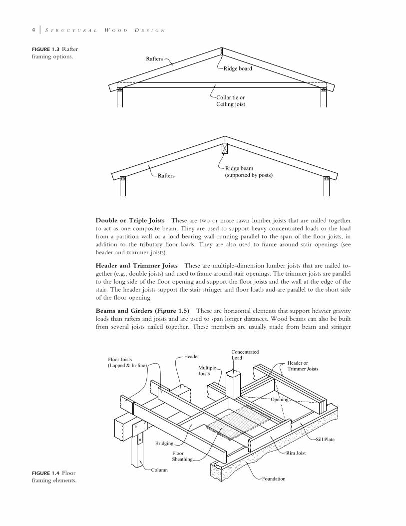
FIGURE 1.4 Floorframing elements.
Double or Triple Joists These are two or more sawn-lumber joists that are nailed togetherto act as one composite beam. They are used to support heavy concentrated loads or the loadfrom a partition wall or a load-bearing wall running parallel to the span of the floor joists, inaddition to the tributary floor loads. They are also used to frame around stair openings (seeheader and trimmer joists).
Header and Trimmer Joists These are multiple-dimension lumber joists that are nailed to-gether (e.g., double joists) and used to frame around stair openings. The trimmer joists are parallelto the long side of the floor opening and support the floor joists and the wall at the edge of thestair. The header joists support the stair stringer and floor loads and are parallel to the short sideof the floor opening.
Beams and Girders (Figure 1.5) These are horizontal elements that support heavier gravityloads than rafters and joists and are used to span longer distances. Wood beams can also be builtfrom several joists nailed together. These members are usually made from beam and stringer
I N T R O D U C T I O N : W O O D P R O P E R T I E S , S P E C I E S , A N D G R A D E S � 5
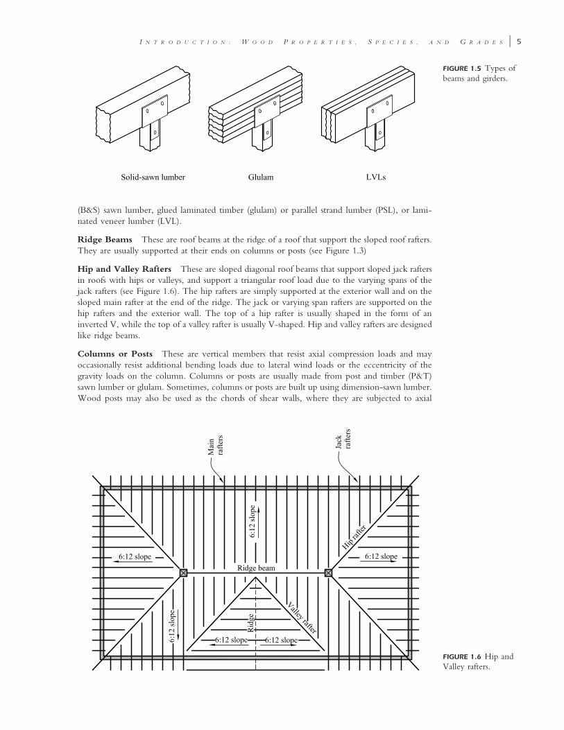
FIGURE 1.5 Types ofbeams and girders.
FIGURE 1.6 Hip andValley rafters.
(B&S) sawn lumber, glued laminated timber (glulam) or parallel strand lumber (PSL), or lami-nated veneer lumber (LVL).
Ridge Beams These are roof beams at the ridge of a roof that support the sloped roof rafters.They are usually supported at their ends on columns or posts (see Figure 1.3)
Hip and Valley Rafters These are sloped diagonal roof beams that support sloped jack raftersin roofs with hips or valleys, and support a triangular roof load due to the varying spans of thejack rafters (see Figure 1.6). The hip rafters are simply supported at the exterior wall and on thesloped main rafter at the end of the ridge. The jack or varying span rafters are supported on thehip rafters and the exterior wall. The top of a hip rafter is usually shaped in the form of aninverted V, while the top of a valley rafter is usually V-shaped. Hip and valley rafters are designedlike ridge beams.
Columns or Posts These are vertical members that resist axial compression loads and mayoccasionally resist additional bending loads due to lateral wind loads or the eccentricity of thegravity loads on the column. Columns or posts are usually made from post and timber (P&T)sawn lumber or glulam. Sometimes, columns or posts are built up using dimension-sawn lumber.Wood posts may also be used as the chords of shear walls, where they are subjected to axial
6 � S T R U C T U R A L W O O D D E S I G N
tension or compression forces from the overturning effect of the lateral and seismic loads on thebuilding.
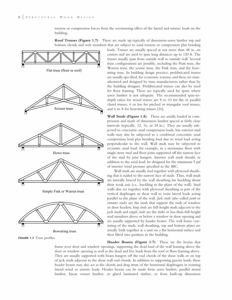
Roof Trusses (Figure 1.7) These are made up typically of dimension-sawn lumber top andbottom chords and web members that are subject to axial tension or compression plus bending
FIGURE 1.7 Truss profiles.
loads. Trusses are usually spaced at not more than 48 in. oncenters and are used to span long distances up to 120 ft. Thetrusses usually span from outside wall to outside wall. Severaltruss configurations are possible, including the Pratt truss, theWarren truss, the scissor truss, the Fink truss, and the bow-string truss. In building design practice, prefabricated trussesare usually specified, for economic reasons, and these are man-ufactured and designed by truss manufacturers rather than bythe building designer. Prefabricated trusses can also be usedfor floor framing. These are typically used for spans wheresawn lumber is not adequate. The recommended span-to-depth ratios for wood trusses are 8 to 10 for flat or parallelchord trusses, 6 or less for pitched or triangular roof trusses,and 6 to 8 for bowstring trusses [16].
Wall Studs (Figure 1.8) These are axially loaded in com-pression and made of dimension lumber spaced at fairly closeintervals (typically, 12, 16, or 24 in.). They are usually sub-jected to concentric axial compression loads, but exterior studwalls may also be subjected to a combined concentric axialcompression load plus bending load due to wind load actingperpendicular to the wall. Wall studs may be subjected toeccentric axial load: for example, in a mezzanine floor withsingle-story stud and floor joists supported off the narrow faceof the stud by joist hangers. Interior wall studs should, inaddition to the axial load, be designed for the minimum 5 psfof interior wind pressure specified in the IBC.
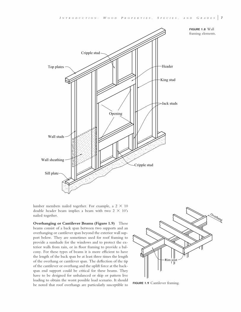
Wall studs are usually tied together with plywood sheath-ing that is nailed to the narrow face of studs. Thus, wall studsare laterally braced by the wall sheathing for buckling abouttheir weak axis (i.e., buckling in the plane of the wall). Studwalls also act together with plywood sheathing as part of thevertical diaphragm or shear wall to resist lateral loads actingparallel to the plane of the wall. Jack studs (also called jamb ortrimmer studs) are the studs that support the ends of windowor door headers; king studs are full-height studs adjacent to thejack studs and cripple studs are the stubs or less-than-full-heightstud members above or below a window or door opening andare usually supported by header beams. The wall frame con-sisting of the studs, wall sheathing, top and bottom plates areusually built together as a unit on a flat horizontal surface andthen lifted into position in the building.
Header Beams (Figure 1.7) These are the beams thatframe over door and window openings, supporting the dead load of the wall framing above thedoor or window opening as well as the dead and live loads from the roof or floor framing above.They are usually supported with beam hangers off the end chords of the shear walls or on topof jack studs adjacent to the shear wall end chords. In addition to supporting gravity loads, theseheader beams may also act as the chords and drag struts of the horizontal diaphragms in resistinglateral wind or seismic loads. Header beams can be made from sawn lumber, parallel strandlumber, linear veneer lumber, or glued laminated timber, or from built-up dimension
I N T R O D U C T I O N : W O O D P R O P E R T I E S , S P E C I E S , A N D G R A D E S � 7
FIGURE 1.8 Wallframing elements.
FIGURE 1.9 Cantilever framing.
lumber members nailed together. For example, a 2 � 10double header beam implies a beam with two 2 � 10’snailed together.
Overhanging or Cantilever Beams (Figure 1.9) Thesebeams consist of a back span between two supports and anoverhanging or cantilever span beyond the exterior wall sup-port below. They are sometimes used for roof framing toprovide a sunshade for the windows and to protect the ex-terior walls from rain, or in floor framing to provide a bal-cony. For these types of beams it is more efficient to havethe length of the back span be at least three times the lengthof the overhang or cantilever span. The deflection of the tipof the cantilever or overhang and the uplift force at the back-span end support could be critical for these beams. Theyhave to be designed for unbalanced or skip or pattern liveloading to obtain the worst possible load scenario. It shouldbe noted that roof overhangs are particularly susceptible to
8 � S T R U C T U R A L W O O D D E S I G N
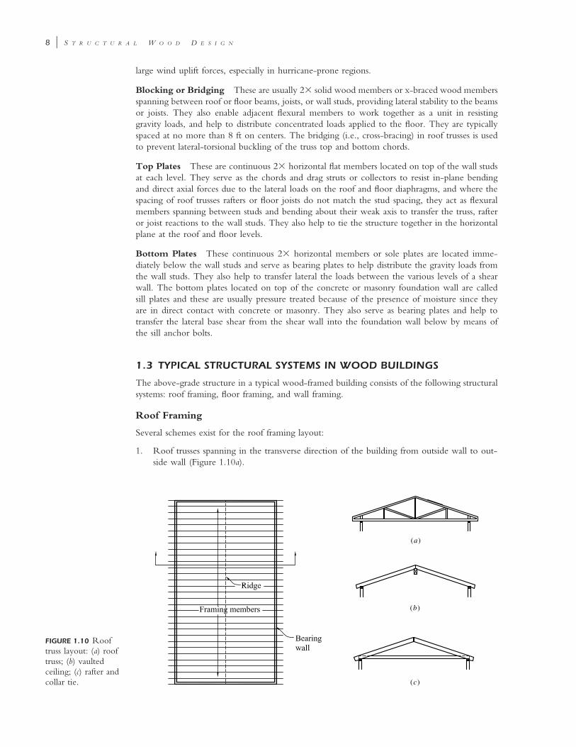
FIGURE 1.10 Rooftruss layout: (a) rooftruss; (b) vaultedceiling; (c) rafter andcollar tie.
(a)
(c)
(b)
large wind uplift forces, especially in hurricane-prone regions.
Blocking or Bridging These are usually 2� solid wood members or x-braced wood membersspanning between roof or floor beams, joists, or wall studs, providing lateral stability to the beamsor joists. They also enable adjacent flexural members to work together as a unit in resistinggravity loads, and help to distribute concentrated loads applied to the floor. They are typicallyspaced at no more than 8 ft on centers. The bridging (i.e., cross-bracing) in roof trusses is usedto prevent lateral-torsional buckling of the truss top and bottom chords.
Top Plates These are continuous 2� horizontal flat members located on top of the wall studsat each level. They serve as the chords and drag struts or collectors to resist in-plane bendingand direct axial forces due to the lateral loads on the roof and floor diaphragms, and where thespacing of roof trusses rafters or floor joists do not match the stud spacing, they act as flexuralmembers spanning between studs and bending about their weak axis to transfer the truss, rafteror joist reactions to the wall studs. They also help to tie the structure together in the horizontalplane at the roof and floor levels.
Bottom Plates These continuous 2� horizontal members or sole plates are located imme-diately below the wall studs and serve as bearing plates to help distribute the gravity loads fromthe wall studs. They also help to transfer lateral the loads between the various levels of a shearwall. The bottom plates located on top of the concrete or masonry foundation wall are calledsill plates and these are usually pressure treated because of the presence of moisture since theyare in direct contact with concrete or masonry. They also serve as bearing plates and help totransfer the lateral base shear from the shear wall into the foundation wall below by means ofthe sill anchor bolts.
1.3 TYPICAL STRUCTURAL SYSTEMS IN WOOD BUILDINGS
The above-grade structure in a typical wood-framed building consists of the following structuralsystems: roof framing, floor framing, and wall framing.
Roof Framing
Several schemes exist for the roof framing layout:
1. Roof trusses spanning in the transverse direction of the building from outside wall to out-side wall (Figure 1.10a).
I N T R O D U C T I O N : W O O D P R O P E R T I E S , S P E C I E S , A N D G R A D E S � 9
(a)
(b)
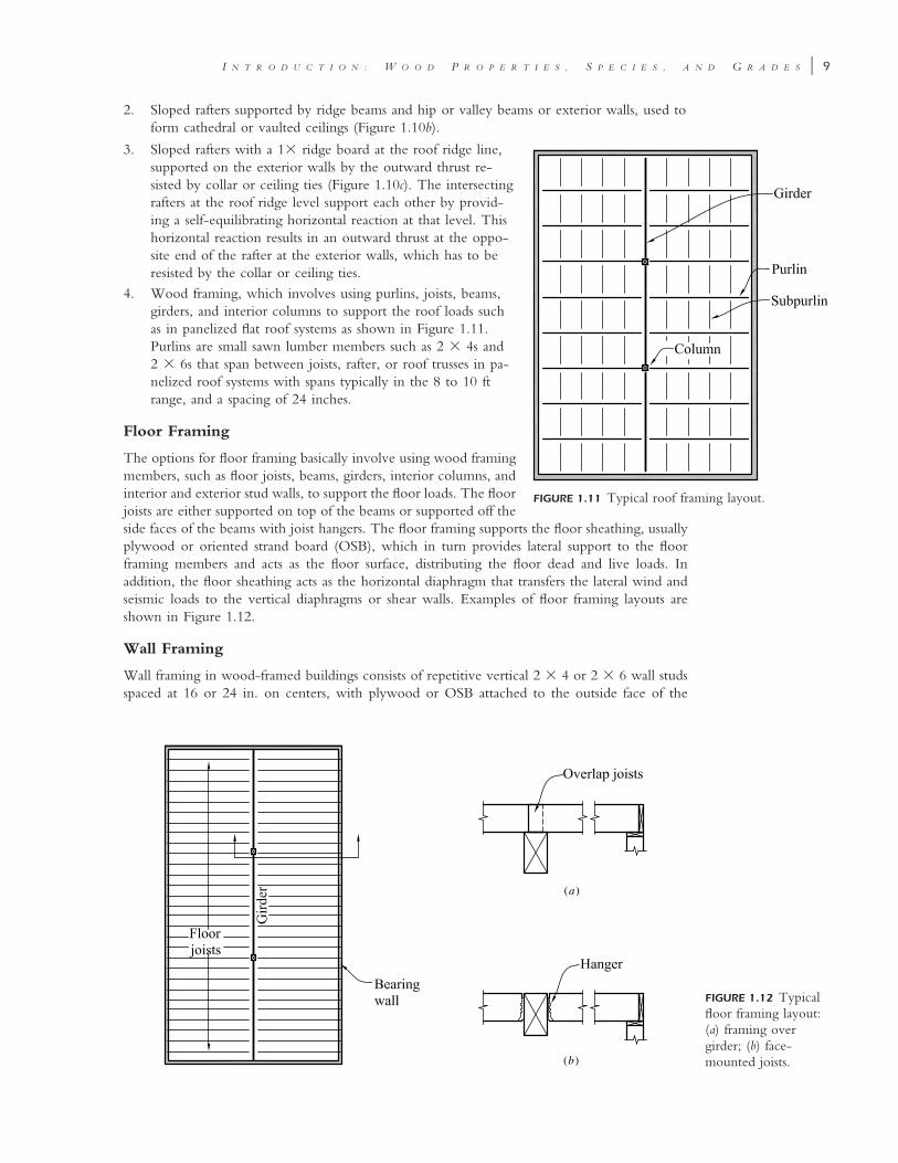
FIGURE 1.12 Typicalfloor framing layout:(a) framing overgirder; (b) face-mounted joists.
2. Sloped rafters supported by ridge beams and hip or valley beams or exterior walls, used toform cathedral or vaulted ceilings (Figure 1.10b).
FIGURE 1.11 Typical roof framing layout.
3. Sloped rafters with a 1� ridge board at the roof ridge line,supported on the exterior walls by the outward thrust re-sisted by collar or ceiling ties (Figure 1.10c). The intersectingrafters at the roof ridge level support each other by provid-ing a self-equilibrating horizontal reaction at that level. Thishorizontal reaction results in an outward thrust at the oppo-site end of the rafter at the exterior walls, which has to beresisted by the collar or ceiling ties.
4. Wood framing, which involves using purlins, joists, beams,girders, and interior columns to support the roof loads suchas in panelized flat roof systems as shown in Figure 1.11.Purlins are small sawn lumber members such as 2 � 4s and2 � 6s that span between joists, rafter, or roof trusses in pa-nelized roof systems with spans typically in the 8 to 10 ftrange, and a spacing of 24 inches.
Floor Framing
The options for floor framing basically involve using wood framingmembers, such as floor joists, beams, girders, interior columns, andinterior and exterior stud walls, to support the floor loads. The floorjoists are either supported on top of the beams or supported off theside faces of the beams with joist hangers. The floor framing supports the floor sheathing, usuallyplywood or oriented strand board (OSB), which in turn provides lateral support to the floorframing members and acts as the floor surface, distributing the floor dead and live loads. Inaddition, the floor sheathing acts as the horizontal diaphragm that transfers the lateral wind andseismic loads to the vertical diaphragms or shear walls. Examples of floor framing layouts areshown in Figure 1.12.
Wall Framing
Wall framing in wood-framed buildings consists of repetitive vertical 2 � 4 or 2 � 6 wall studsspaced at 16 or 24 in. on centers, with plywood or OSB attached to the outside face of the
10 � S T R U C T U R A L W O O D D E S I G N
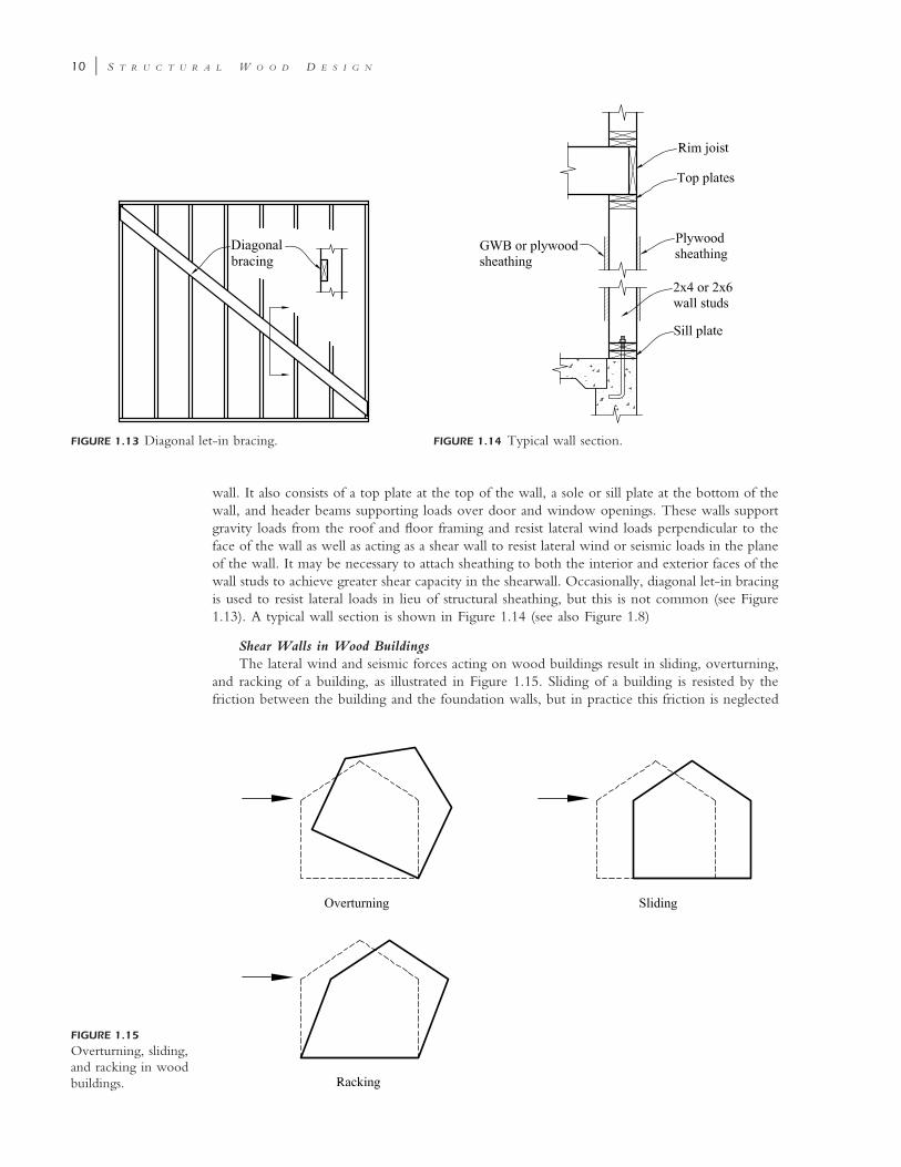
FIGURE 1.13 Diagonal let-in bracing. FIGURE 1.14 Typical wall section.
FIGURE 1.15
Overturning, sliding,and racking in woodbuildings.
wall. It also consists of a top plate at the top of the wall, a sole or sill plate at the bottom of thewall, and header beams supporting loads over door and window openings. These walls supportgravity loads from the roof and floor framing and resist lateral wind loads perpendicular to theface of the wall as well as acting as a shear wall to resist lateral wind or seismic loads in the planeof the wall. It may be necessary to attach sheathing to both the interior and exterior faces of thewall studs to achieve greater shear capacity in the shearwall. Occasionally, diagonal let-in bracingis used to resist lateral loads in lieu of structural sheathing, but this is not common (see Figure1.13). A typical wall section is shown in Figure 1.14 (see also Figure 1.8)
Shear Walls in Wood BuildingsThe lateral wind and seismic forces acting on wood buildings result in sliding, overturning,
and racking of a building, as illustrated in Figure 1.15. Sliding of a building is resisted by thefriction between the building and the foundation walls, but in practice this friction is neglected
I N T R O D U C T I O N : W O O D P R O P E R T I E S , S P E C I E S , A N D G R A D E S � 11
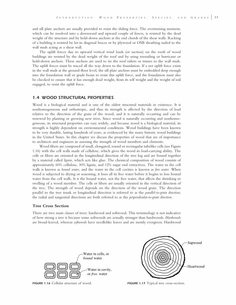
FIGURE 1.16 Cellular structure of wood. FIGURE 1.17 Typical tree cross-section.
and sill plate anchors are usually provided to resist the sliding force. The overturning moment,which can be resolved into a downward and upward couple of forces, is resisted by the deadweight of the structure and by hold-down anchors at the end chords of the shear walls. Rackingof a building is resisted by let-in diagonal braces or by plywood or OSB sheathing nailed to thewall studs acting as a shear wall.
The uplift forces due to upward vertical wind loads (or suction) on the roofs of woodbuildings are resisted by the dead weight of the roof and by using toenailing or hurricane orhold-down anchors. These anchors are used to tie the roof rafters or trusses to the wall studs.The uplift forces must be traced all the way down to the foundation. If a net uplift force existsin the wall studs at the ground-floor level, the sill plate anchors must be embedded deep enoughinto the foundation wall or grade beam to resist this uplift force, and the foundation must alsobe checked to ensure that it has enough dead weight, from its self weight and the weight of soilengaged, to resist the uplift force.
1.4 WOOD STRUCTURAL PROPERTIES
Wood is a biological material and is one of the oldest structural materials in existence. It isnonhomogeneous and orthotropic, and thus its strength is affected by the direction of loadrelative to the direction of the grain of the wood, and it is naturally occurring and can berenewed by planting or growing new trees. Since wood is naturally occurring and nonhomo-geneous, its structural properties can vary widely, and because wood is a biological material, itsstrength is highly dependent on environmental conditions. Wood buildings have been knownto be very durable, lasting hundreds of years, as evidenced by the many historic wood buildingsin the United States. In this chapter we discuss the properties of wood that are of importanceto architects and engineers in assessing the strength of wood members and elements.
Wood fibers are composed of small, elongated, round or rectangular tubelike cells (see Figure1.16) with the cell walls made of cellulose, which gives the wood its load-carrying ability. Thecells or fibers are oriented in the longitudinal direction of the tree log and are bound togetherby a material called lignin, which acts like glue. The chemical composition of wood consists ofapproximately 60% cellulose, 30% lignin, and 12% sugar end extractives. The water in the cellwalls is known as bound water, and the water in the cell cavities is known as free water. Whenwood is subjected to drying or seasoning, it loses all its free water before it begins to lose boundwater from the cell walls. It is the bound water, not the free water, that affects the shrinking orswelling of a wood member. The cells or fibers are usually oriented in the vertical direction ofthe tree. The strength of wood depends on the direction of the wood grain. The directionparallel to the tree trunk or longitudinal direction is referred to as the parallel-to-grain direction;the radial and tangential directions are both referred to as the perpendicular-to-grain direction.
Tree Cross Section
There are two main classes of trees: hardwood and softwood. This terminology is not indicativeof how strong a tree is because some softwoods are actually stronger than hardwoods. Hardwoodsare broad-leaved, whereas softwoods have needlelike leaves and are mostly evergreen. Hardwood
12 � S T R U C T U R A L W O O D D E S I G N
trees take longer to mature and grow than softwoods, are mostly tropical, and are generally moredense than softwoods. Consequently, they are more expensive and used less frequently thansoftwood lumber or timber in wood building construction in the United States. Softwoodsconstitute more than 75% of all lumber used in construction in the United States [6], and morethan two-thirds of softwood lumber are western woods such as douglas fir-larch and spruce. Therest are eastern woods such as southern pine. Examples of hardwood trees include balsa, oak,birch, and basswood.
A typical tree cross section is shown Figure 1.17. The growth of timber trees is indicatedby an annual growth ring added each year to the outer surface of the tree trunk just beneaththe bark. The age of a tree can be determined from the number of annual rings in a cross sectionof the tree log at its base. The tree cross section shows the two main sections of the tree, thesapwood and the heartwood. Sapwood is light in color and may be as strong as heartwood, butit is less resistant to decay. Heartwood is darker and older and more resistant to decay. However,sapwood is lighter and more amenable than heartwood to pressure treatment. Heartwood isdarker and functions as a mechanical support for a tree, while sapwood contains living cells fornourishment of the tree.
Advantages and Disadvantages of Wood as a Structural Material
Some advantages of wood as a structural material are as follows:
• Wood is renewable.• Wood is machinable.• Wood has a good strength-to-weight ratio.• Wood will not rust.• Wood is aesthetically pleasing.
The disadvantages of wood include the following:
• Wood can burn.• Wood can decay or rot and can be attacked by insects such as termites and marine borers.
Moisture and air promote decay and rot in wood.• Wood holds moisture.• Wood is susceptible to volumetric instability (i.e., wood shrinks).• Wood’s properties are highly variable and vary widely between species and even between
trees of the same species. There is also variation in strength within the cross section of atree log.
1.5 FACTORS AFFECTING THE STRENGTH OF WOOD
Several factors that affect the strength of a wood member are discussed in this section: (1) speciesgroup, (2) moisture content, (3) duration of loading, (4) size and shape of the wood member,(5) defects, (6) direction of the primary stress with respect to the orientation of the wood grain,and (7) ambient temperature.
Species and Species Group
Structural lumber is produced from several species of trees. Some of the species are groupedtogether to form a species group, whose members are ‘‘grown, harvested and manufactured to-gether.’’ The NDS code’s tabulated stresses for a species group were derived statistically fromthe results of a large number of tests to ensure that all the stresses tabulated for all species withina species group are conservative and safe. A species group is a combination of two or morespecies. For example, Douglas fir-larch is a species group that is obtained from a combinationof Douglas fir and western larch species. Hem-fir is a species group that can be obtained froma combination of western hemlock and white fir.
Structural wood members are derived from different stocks of trees, and the choice of woodspecies for use in design is typically a matter of economics and regional availability. For a given
I N T R O D U C T I O N : W O O D P R O P E R T I E S , S P E C I E S , A N D G R A D E S � 13
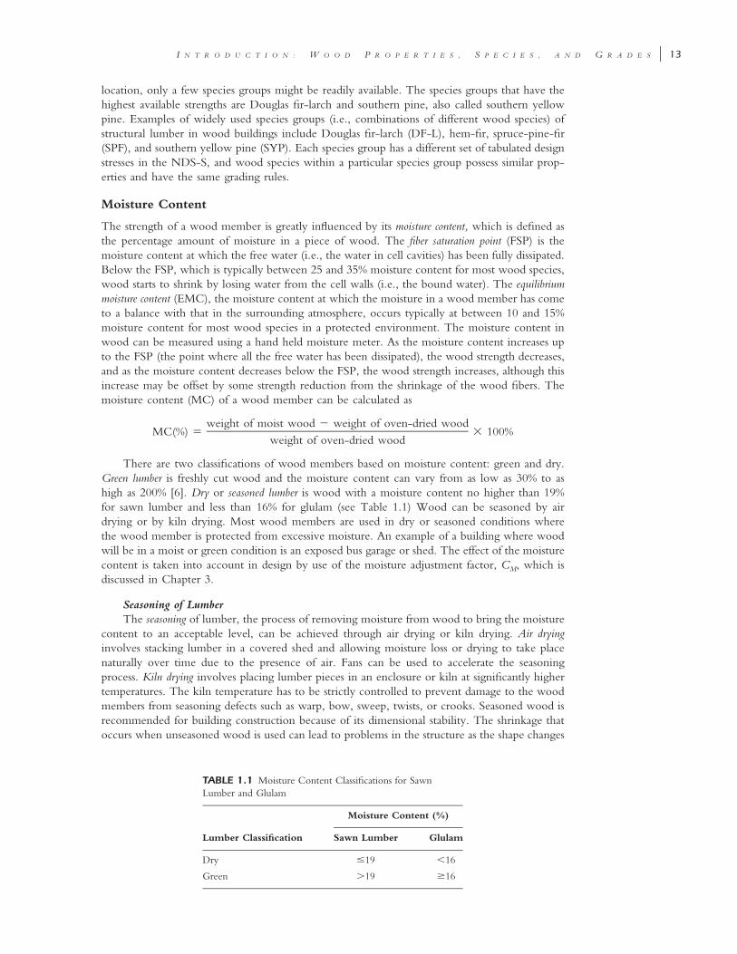
TABLE 1.1 Moisture Content Classifications for SawnLumber and Glulam
Lumber Classification
Moisture Content (%)
Sawn Lumber Glulam
Dry �19 �16
Green �19 �16
location, only a few species groups might be readily available. The species groups that have thehighest available strengths are Douglas fir-larch and southern pine, also called southern yellowpine. Examples of widely used species groups (i.e., combinations of different wood species) ofstructural lumber in wood buildings include Douglas fir-larch (DF-L), hem-fir, spruce-pine-fir(SPF), and southern yellow pine (SYP). Each species group has a different set of tabulated designstresses in the NDS-S, and wood species within a particular species group possess similar prop-erties and have the same grading rules.
Moisture Content
The strength of a wood member is greatly influenced by its moisture content, which is defined asthe percentage amount of moisture in a piece of wood. The fiber saturation point (FSP) is themoisture content at which the free water (i.e., the water in cell cavities) has been fully dissipated.Below the FSP, which is typically between 25 and 35% moisture content for most wood species,wood starts to shrink by losing water from the cell walls (i.e., the bound water). The equilibriummoisture content (EMC), the moisture content at which the moisture in a wood member has cometo a balance with that in the surrounding atmosphere, occurs typically at between 10 and 15%moisture content for most wood species in a protected environment. The moisture content inwood can be measured using a hand held moisture meter. As the moisture content increases upto the FSP (the point where all the free water has been dissipated), the wood strength decreases,and as the moisture content decreases below the FSP, the wood strength increases, although thisincrease may be offset by some strength reduction from the shrinkage of the wood fibers. Themoisture content (MC) of a wood member can be calculated as
weight of moist wood � weight of oven-dried woodMC(%) � � 100%
weight of oven-dried wood
There are two classifications of wood members based on moisture content: green and dry.Green lumber is freshly cut wood and the moisture content can vary from as low as 30% to ashigh as 200% [6]. Dry or seasoned lumber is wood with a moisture content no higher than 19%for sawn lumber and less than 16% for glulam (see Table 1.1) Wood can be seasoned by airdrying or by kiln drying. Most wood members are used in dry or seasoned conditions wherethe wood member is protected from excessive moisture. An example of a building where woodwill be in a moist or green condition is an exposed bus garage or shed. The effect of the moisturecontent is taken into account in design by use of the moisture adjustment factor, CM, which isdiscussed in Chapter 3.
Seasoning of LumberThe seasoning of lumber, the process of removing moisture from wood to bring the moisture
content to an acceptable level, can be achieved through air drying or kiln drying. Air dryinginvolves stacking lumber in a covered shed and allowing moisture loss or drying to take placenaturally over time due to the presence of air. Fans can be used to accelerate the seasoningprocess. Kiln drying involves placing lumber pieces in an enclosure or kiln at significantly highertemperatures. The kiln temperature has to be strictly controlled to prevent damage to the woodmembers from seasoning defects such as warp, bow, sweep, twists, or crooks. Seasoned wood isrecommended for building construction because of its dimensional stability. The shrinkage thatoccurs when unseasoned wood is used can lead to problems in the structure as the shape changes
14 � S T R U C T U R A L W O O D D E S I G N
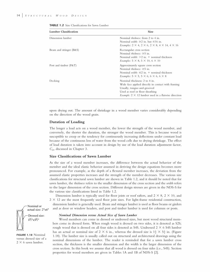
TABLE 1.2 Size Classifications for Sawn Lumber
Lumber Classification Size
Dimension lumber Nominal thickness: from 2 to 4 in.Nominal width: �2 in. but �16 in.Examples: 2 � 4, 2 � 6, 2 � 8, 4 � 14, 4 � 16
Beam and stringer (B&S) Rectangular cross sectionNominal thickness: �5 in.Nominal width: �2 in. � nominal thicknessExamples: 5 � 8, 5 � 10, 6 � 10
Post and timber (P&T) Approximately square cross sectionNominal thickness: �5 in.Nominal width: �2 in. � nominal thicknessExamples: 5 � 5, 5 � 6, 6 � 6, 6 � 8
Decking Nominal thickness: 2 to 4 in.Wide face applied directly in contact with framingUsually, tongue-and-groovedUsed as roof or floor sheathingExample: 2 � 12 lumber used in a flatwise direction
upon drying out. The amount of shrinkage in a wood member varies considerably dependingon the direction of the wood grain.
Duration of Loading
The longer a load acts on a wood member, the lower the strength of the wood member, andconversely, the shorter the duration, the stronger the wood member. This is because wood issusceptible to creep or the tendency for continuously increasing deflections under constant loadbecause of the continuous loss of water from the wood cells due to drying shrinkage. The effectof load duration is taken into account in design by use of the load duration adjustment factor,CD, discussed in Chapter 3.
Size Classifications of Sawn Lumber
As the size of a wood member increases, the difference between the actual behavior of themember and the ideal elastic behavior assumed in deriving the design equations becomes morepronounced. For example, as the depth of a flexural member increases, the deviation from theassumed elastic properties increases and the strength of the member decreases. The various sizeclassifications for structural sawn lumber are shown in Table 1.2, and it should be noted that forsawn lumber, the thickness refers to the smaller dimension of the cross section and the width refersto the larger dimension of the cross section. Different design stresses are given in the NDS-S forthe various size classifications listed in Table 1.2.
Dimension lumber is typically used for floor joists or roof rafters, and 2 � 8, 2 � 10, and2 � 12 are the most frequently used floor joist sizes. For light-frame residential construction,
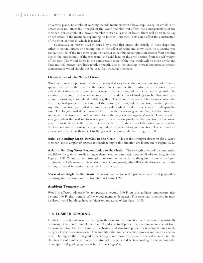
FIGURE 1.18 Nominalversus dressed size of a2 � 6 sawn lumber.
dimension lumber is generally used. Beam and stringer lumber is used as floor beams or girdersand as door or window headers, and post and timber lumber is used for columns or posts.
Nominal Dimension versus Actual Size of Sawn LumberWood members can come in dressed or undressed sizes, but most wood structural mem-
bers come in dressed form. When rough wood is dressed on two sides, it is denoted as S2S;rough wood that is dressed on all four sides is denoted as S4S. Undressed 2 � 6 S4S lumberhas an actual or nominal size of 2 � 6 in., whereas the dressed size is 1 � 5 in. (Figure1 1– –2 2
1.18). The lumber size is usually called out on structural and architectural drawings using thenominal dimensions of the lumber. The reader is reminded that for a sawn lumber crosssection, the thickness is the smaller dimension and the width is the larger dimension of thecross section. In this book we assume that all wood is dressed on four sides (i.e., S4S). Sectionproperties for wood members are given in Tables 1A and 1B of NDS-S [2].
I N T R O D U C T I O N : W O O D P R O P E R T I E S , S P E C I E S , A N D G R A D E S � 15
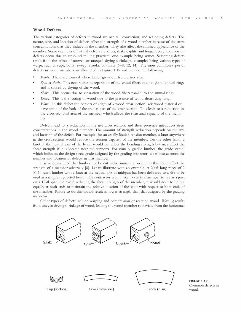
FIGURE 1.19
Common defects inwood.
Wood Defects
The various categories of defects in wood are natural, conversion, and seasoning defects. Thenature, size, and location of defects affect the strength of a wood member because of the stressconcentrations that they induce in the member. They also affect the finished appearance of themember. Some examples of natural defects are knots, shakes, splits, and fungal decay. Conversiondefects occur due to unsound milling practices, one example being wanes. Seasoning defectsresult from the effect of uneven or unequal drying shrinkage, examples being various types ofwarps, such as cups, bows, sweep, crooks, or twists [6–8, 12, 14]. The most common types ofdefects in wood members are illustrated in Figure 1.19 and include the following:
• Knots. These are formed where limbs grow out from a tree stem.• Split or check. This occurs due to separation of the wood fibers at an angle to annual rings
and is caused by drying of the wood.• Shake. This occurs due to separation of the wood fibers parallel to the annual rings.• Decay. This is the rotting of wood due to the presence of wood-destroying fungi.• Wane. In this defect the corners or edges of a wood cross section lack wood material or
have some of the bark of the tree as part of the cross section. This leads to a reduction inthe cross-sectional area of the member which affects the structural capacity of the mem-ber.
Defects lead to a reduction in the net cross section, and their presence introduces stressconcentrations in the wood member. The amount of strength reduction depends on the sizeand location of the defect. For example, for an axially loaded tension member, a knot anywherein the cross section would reduce the tension capacity of the member. On the other hand, aknot at the neutral axis of the beam would not affect the bending strength but may affect theshear strength if it is located near the supports. For visually graded lumber, the grade stamp,which indicates the design stress grade assigned by the grading inspector, takes into account thenumber and location of defects in that member.
It is recommended that lumber not be cut indiscriminately on site, as this could affect thestrength of a member adversely [8]. Let us illustrate with an example. A 20-ft-long piece of 2� 14 sawn lumber with a knot at the neutral axis at midspan has been delivered to a site to beused as a simply supported beam. The contractor would like to cut this member to use as a joiston a 12-ft span. To avoid reducing the shear strength of the member, it would need to be cutequally at both ends to maintain the relative location of the knot with respect to both ends ofthe member. Failure to do this would result in lower strength than that assigned by the gradinginspector.
Other types of defects include warping and compression or reaction wood. Warping resultsfrom uneven drying shrinkage of wood, leading the wood member to deviate from the horizontal
16 � S T R U C T U R A L W O O D D E S I G N
or vertical plane. Examples of warping include members with a bow, cup, sweep, or crook. Thisdefect does not affect the strength of the wood member but affects the constructability of themember. For example, if a bowed member is used as a joist or beam, there will be an initial sagor deflection in the member, depending on how it is oriented. This could affect the constructionof the floor or roof in which it is used.
Compression or reaction wood is caused by a tree that grows abnormally in bent shape dueeither to natural effects or bending due to the effect of wind and snow loads. In a leaning treetrunk, one side of the tree cross section is subject to combined compression stresses from bendingdue to the crookedness of the tree trunk and axial load on the cross section from the self-weightof the tree. The wood fibers in the compression zone of the tree trunk will be more brittle andhard and will possess very little tensile strength, due to the existing internal compressive stresses.Compression wood should not be used for structural members.
Orientation of the Wood Grain
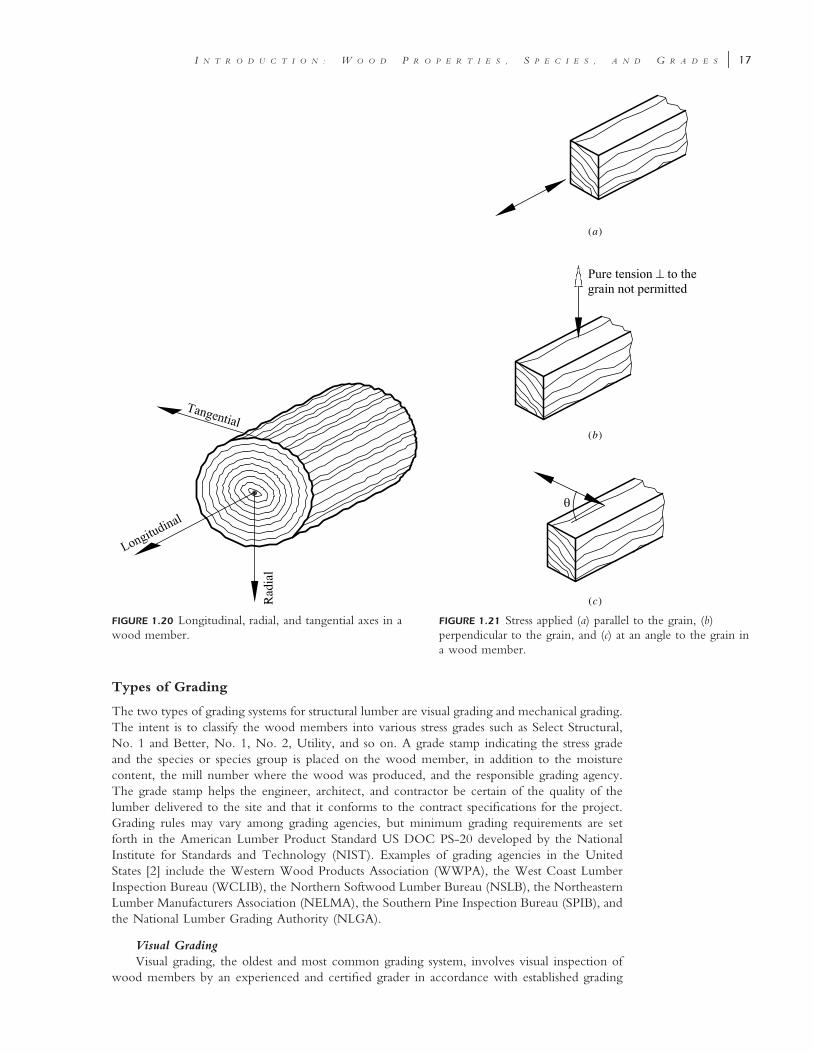
Wood is an orthotropic material with strengths that vary depending on the direction of the stressapplied relative to the grain of the wood. As a result of the tubular nature of wood, threeindependent directions are present in a wood member: longitudinal, radial, and tangential. Thevariation in strength in a wood member with the direction of loading can be illustrated by agroup of drinking straws glued tightly together. The group of straws will be strongest when theload is applied parallel to the length of the straws (i.e., longitudinal direction); loads applied inany other direction (i.e., radial or tangential) will crush the walls of the straws or pull apart theglue. The longitudinal direction is referred to as the parallel-to-grain direction, and the tangentialand radial directions are both referred to as the perpendicular-to-grain direction. Thus, wood isstrongest when the load or stress is applied in a direction parallel to the direction of the woodgrain, is weakest when the stress is perpendicular to the direction of the wood grain, and hasthe least amount of shrinkage in the longitudinal or parallel-to-grain direction. The various axesin a wood member with respect to the grain direction are shown in Figure 1.20.
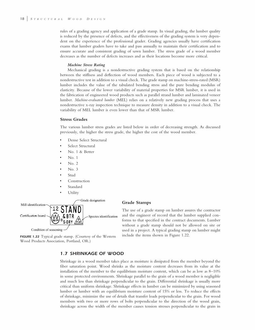
Axial or Bending Stress Parallel to the Grain This is the strongest direction for a woodmember, and examples of stresses and loads acting in this direction are illustrated in Figure 1.21a.
Axial or Bending Stress Perpendicular to the Grain The strength of wood in compressionparallel to the grain is usually stronger than wood in compression perpendicular to the grain (seeFigure 1.21b). Wood has zero strength in tension perpendicular to the grain since only the ligninor glue is available to resist this tension force. Consequently, the NDS code does not permit theloading of wood in tension perpendicular to the grain.
Stress at an Angle to the Grain This case lies between the parallel-to-grain and perpendic-ular-to-grain directions and is illustrated in Figure 1.21c.
Ambient Temperature
Wood is affected adversely by temperature beyond 100�F. As the ambient temperature risesbeyond 100�F, the strength of the wood member decreases. The structural members in mostinsulated wood buildings have ambient temperatures of less than 100�F.
1.6 LUMBER GRADING
Lumber is usually cut from a tree log in the longitudinal direction, and because it is naturallyoccurring, it has quite variable mechanical and structural properties, even for members cut fromthe same tree log. Lumber of similar mechanical and structural properties is grouped into a singlecategory known as a stress grade. This simplifies the lumber selection process and increases econ-omy. The higher the stress grade, the stronger and more expensive the wood member is. Theclassification of lumber with regard to strength, usage, and defects according to the grading rulesof an approved grading agency is termed lumber grading.
I N T R O D U C T I O N : W O O D P R O P E R T I E S , S P E C I E S , A N D G R A D E S � 17
FIGURE 1.20 Longitudinal, radial, and tangential axes in awood member.
(a)
(b)
(c)
FIGURE 1.21 Stress applied (a) parallel to the grain, (b)perpendicular to the grain, and (c) at an angle to the grain ina wood member.
Types of Grading
The two types of grading systems for structural lumber are visual grading and mechanical grading.The intent is to classify the wood members into various stress grades such as Select Structural,No. 1 and Better, No. 1, No. 2, Utility, and so on. A grade stamp indicating the stress gradeand the species or species group is placed on the wood member, in addition to the moisturecontent, the mill number where the wood was produced, and the responsible grading agency.The grade stamp helps the engineer, architect, and contractor be certain of the quality of thelumber delivered to the site and that it conforms to the contract specifications for the project.Grading rules may vary among grading agencies, but minimum grading requirements are setforth in the American Lumber Product Standard US DOC PS-20 developed by the NationalInstitute for Standards and Technology (NIST). Examples of grading agencies in the UnitedStates [2] include the Western Wood Products Association (WWPA), the West Coast LumberInspection Bureau (WCLIB), the Northern Softwood Lumber Bureau (NSLB), the NortheasternLumber Manufacturers Association (NELMA), the Southern Pine Inspection Bureau (SPIB), andthe National Lumber Grading Authority (NLGA).
Visual GradingVisual grading, the oldest and most common grading system, involves visual inspection of
wood members by an experienced and certified grader in accordance with established grading
18 � S T R U C T U R A L W O O D D E S I G N
rules of a grading agency and application of a grade stamp. In visual grading, the lumber qualityis reduced by the presence of defects, and the effectiveness of the grading system is very depen-dent on the experience of the professional grader. Grading agencies usually have certificationexams that lumber graders have to take and pass annually to maintain their certification and toensure accurate and consistent grading of sawn lumber. The stress grade of a wood memberdecreases as the number of defects increases and as their locations become more critical.
Machine Stress RatingMechanical grading is a nondestructive grading system that is based on the relationship
between the stiffness and deflection of wood members. Each piece of wood is subjected to anondestructive test in addition to a visual check. The grade stamp on machine-stress-rated (MSR)lumber includes the value of the tabulated bending stress and the pure bending modulus ofelasticity. Because of the lower variability of material properties for MSR lumber, it is used inthe fabrication of engineered wood products such as parallel strand lumber and laminated veneerlumber. Machine-evaluated lumber (MEL) relies on a relatively new grading process that uses anondestructive x-ray inspection technique to measure density in addition to a visual check. Thevariability of MEL lumber is even lower than that of MSR lumber.
Stress Grades
The various lumber stress grades are listed below in order of decreasing strength. As discussedpreviously, the higher the stress grade, the higher the cost of the wood member.
• Dense Select Structural• Select Structural• No. 1 & Better• No. 1• No. 2• No. 3• Stud• Construction• Standard• Utility
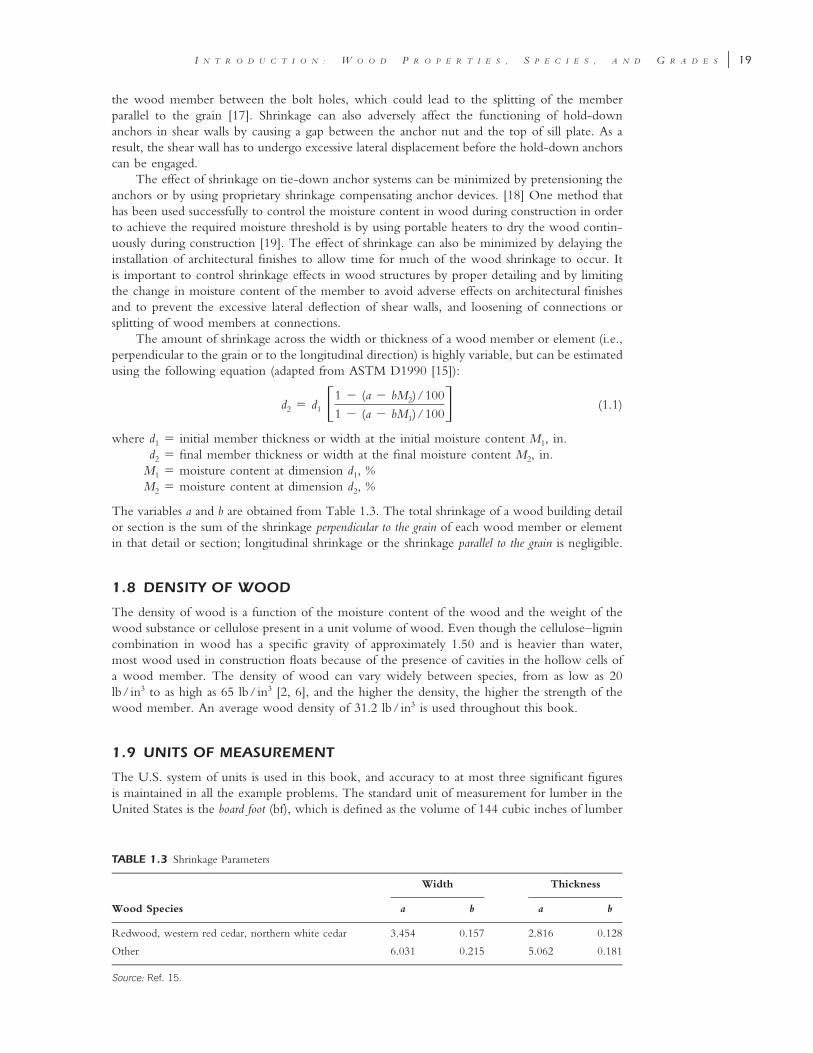
FIGURE 1.22 Typical grade stamp. (Courtesy of the WesternWood Products Association, Portland, OR.)
Grade Stamps
The use of a grade stamp on lumber assures the contractorand the engineer of record that the lumber supplied con-forms to that specified in the contract documents. Lumberwithout a grade stamp should not be allowed on site orused in a project. A typical grading stamp on lumber mightinclude the items shown in Figure 1.22.
1.7 SHRINKAGE OF WOOD
Shrinkage in a wood member takes place as moisture is dissipated from the member beyond thefiber saturation point. Wood shrinks as the moisture content decreases from its value at theinstallation of the member to the equilibrium moisture content, which can be as low as 8–10%in some protected environments. Shrinkage parallel to the grain of a wood member is negligibleand much less than shrinkage perpendicular to the grain. Differential shrinkage is usually morecritical than uniform shrinkage. Shrinkage effects in lumber can be minimized by using seasonedlumber or lumber with an equilibrium moisture content of 15% or less. To reduce the effectsof shrinkage, minimize the use of details that transfer loads perpendicular to the grain. For woodmembers with two or more rows of bolts perpendicular to the direction of the wood grain,shrinkage across the width of the member causes tension stresses perpendicular to the grain in
I N T R O D U C T I O N : W O O D P R O P E R T I E S , S P E C I E S , A N D G R A D E S � 19
TABLE 1.3 Shrinkage Parameters
Wood Species
Width
a b
Thickness
a b
Redwood, western red cedar, northern white cedar 3.454 0.157 2.816 0.128
Other 6.031 0.215 5.062 0.181
Source: Ref. 15.
the wood member between the bolt holes, which could lead to the splitting of the memberparallel to the grain [17]. Shrinkage can also adversely affect the functioning of hold-downanchors in shear walls by causing a gap between the anchor nut and the top of sill plate. As aresult, the shear wall has to undergo excessive lateral displacement before the hold-down anchorscan be engaged.
The effect of shrinkage on tie-down anchor systems can be minimized by pretensioning theanchors or by using proprietary shrinkage compensating anchor devices. [18] One method thathas been used successfully to control the moisture content in wood during construction in orderto achieve the required moisture threshold is by using portable heaters to dry the wood contin-uously during construction [19]. The effect of shrinkage can also be minimized by delaying theinstallation of architectural finishes to allow time for much of the wood shrinkage to occur. Itis important to control shrinkage effects in wood structures by proper detailing and by limitingthe change in moisture content of the member to avoid adverse effects on architectural finishesand to prevent the excessive lateral deflection of shear walls, and loosening of connections orsplitting of wood members at connections.
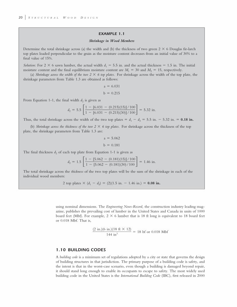
The amount of shrinkage across the width or thickness of a wood member or element (i.e.,perpendicular to the grain or to the longitudinal direction) is highly variable, but can be estimatedusing the following equation (adapted from ASTM D1990 [15]):
1 � (a � bM )/1002d � d (1.1)� �2 1 1 � (a � bM )/1001
where d1 � initial member thickness or width at the initial moisture content M1, in.d2 � final member thickness or width at the final moisture content M2, in.
M1 � moisture content at dimension d1, %M2 � moisture content at dimension d2, %
The variables a and b are obtained from Table 1.3. The total shrinkage of a wood building detailor section is the sum of the shrinkage perpendicular to the grain of each wood member or elementin that detail or section; longitudinal shrinkage or the shrinkage parallel to the grain is negligible.
1.8 DENSITY OF WOOD
The density of wood is a function of the moisture content of the wood and the weight of thewood substance or cellulose present in a unit volume of wood. Even though the cellulose–lignincombination in wood has a specific gravity of approximately 1.50 and is heavier than water,most wood used in construction floats because of the presence of cavities in the hollow cells ofa wood member. The density of wood can vary widely between species, from as low as 20lb/in3 to as high as 65 lb/in3 [2, 6], and the higher the density, the higher the strength of thewood member. An average wood density of 31.2 lb/in3 is used throughout this book.
1.9 UNITS OF MEASUREMENT
The U.S. system of units is used in this book, and accuracy to at most three significant figuresis maintained in all the example problems. The standard unit of measurement for lumber in theUnited States is the board foot (bf), which is defined as the volume of 144 cubic inches of lumber
20 � S T R U C T U R A L W O O D D E S I G N
EXAMPLE 1.1
Shrinkage in Wood Members
Determine the total shrinkage across (a) the width and (b) the thickness of two green 2 � 6 Douglas fir-larchtop plates loaded perpendicular to the grain as the moisture content decreases from an initial value of 30% to afinal value of 15%.
Solution: For 2 � 6 sawn lumber, the actual width d1 � 5.5 in. and the actual thickness � 1.5 in. The initialmoisture content and the final equilibrium moisture content are M1 � 30 and M2 � 15, respectively.
(a) Shrinkage across the width of the two 2 � 6 top plates. For shrinkage across the width of the top plate, theshrinkage parameters from Table 1.3 are obtained as follows:
a � 6.031
b � 0.215
From Equation 1-1, the final width d2 is given as
1 � [6.031 � (0.215)(15)]/100d � 5.5 � 5.32 in.� �2 1 � [6.031 � (0.215)(30)]/100
Thus, the total shrinkage across the width of the two top plates � d1 � d2 � 5.5 in. � 5.32 in. � 0.18 in.
(b) Shrinkage across the thickness of the two 2 � 6 top plates. For shrinkage across the thickness of the topplate, the shrinkage parameters from Table 1.3 are:
a � 5.062
b � 0.181
The final thickness d2 of each top plate from Equation 1-1 is given as
1 � [5.062 � (0.181)(15)]/100d � 1.5 � 1.46 in.� �2 1 � [5.062 � (0.181)(30)/100
The total shrinkage across the thickness of the two top plates will be the sum of the shrinkage in each of theindividual wood members:
2 top plates � (d � d ) � (2)(1.5 in. � 1.46 in.) � 0.08 in.1 2
using nominal dimensions. The Engineering News-Record, the construction industry leading mag-azine, publishes the prevailing cost of lumber in the United States and Canada in units of 1000board feet (Mbf). For example, 2 � 6 lumber that is 18 ft long is equivalent to 18 board feetor 0.018 Mbf. That is,
(2 in.)(6 in.)(18 ft � 12)� 18 bf or 0.018 Mbf3144 in
1.10 BUILDING CODES
A building code is a minimum set of regulations adopted by a city or state that governs the designof building structures in that jurisdiction. The primary purpose of a building code is safety, andthe intent is that in the worst-case scenario, even though a building is damaged beyond repair,it should stand long enough to enable its occupants to escape to safety. The most widely usedbuilding code in the United States is the International Building Code (IBC), first released in 2000
I N T R O D U C T I O N : W O O D P R O P E R T I E S , S P E C I E S , A N D G R A D E S � 21
EXAMPLE 1.2
Shrinkage at Framed Floors
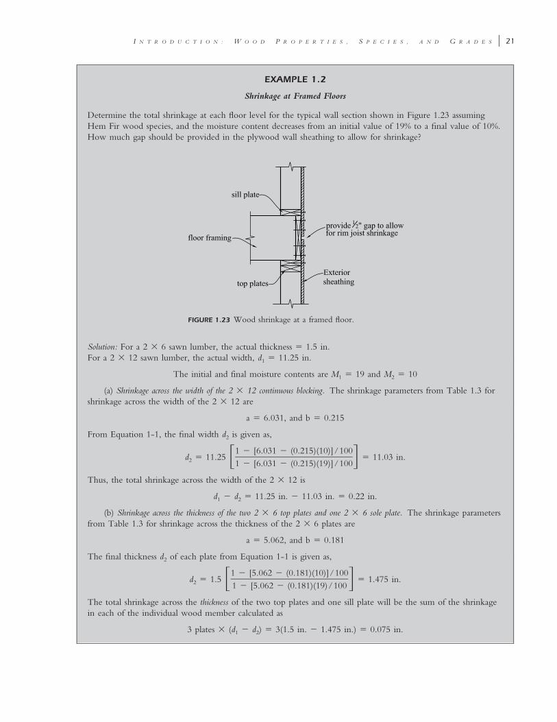
Determine the total shrinkage at each floor level for the typical wall section shown in Figure 1.23 assumingHem Fir wood species, and the moisture content decreases from an initial value of 19% to a final value of 10%.How much gap should be provided in the plywood wall sheathing to allow for shrinkage?
FIGURE 1.23 Wood shrinkage at a framed floor.
Solution: For a 2 � 6 sawn lumber, the actual thickness � 1.5 in.For a 2 � 12 sawn lumber, the actual width, d1 � 11.25 in.
The initial and final moisture contents are M � 19 and M � 101 2
(a) Shrinkage across the width of the 2 � 12 continuous blocking. The shrinkage parameters from Table 1.3 forshrinkage across the width of the 2 � 12 are
a � 6.031, and b � 0.215
From Equation 1-1, the final width d2 is given as,
1 � [6.031 � (0.215)(10)]/100d � 11.25 � 11.03 in.� �2 1 � [6.031 � (0.215)(19)]/100
Thus, the total shrinkage across the width of the 2 � 12 is
d � d � 11.25 in. � 11.03 in. � 0.22 in.1 2
(b) Shrinkage across the thickness of the two 2 � 6 top plates and one 2 � 6 sole plate. The shrinkage parametersfrom Table 1.3 for shrinkage across the thickness of the 2 � 6 plates are
a � 5.062, and b � 0.181
The final thickness d2 of each plate from Equation 1-1 is given as,
1 � [5.062 � (0.181)(10)]/100d � 1.5 � 1.475 in.� �2 1 � [5.062 � (0.181)(19)/100
The total shrinkage across the thickness of the two top plates and one sill plate will be the sum of the shrinkagein each of the individual wood member calculated as
3 plates � (d � d ) � 3(1.5 in. � 1.475 in.) � 0.075 in.1 2
22 � S T R U C T U R A L W O O D D E S I G N
The longitudinal shrinkage or shrinkage parallel to grain in the 2 � 6 studs is negligible. Therefore, the totalshrinkage per floor, which is the sum of the shrinkage of all the wood members at the floor level, is
1–0.075 in. � 0.22 in. � 0.3 in. Therefore, use in. shrinkage gap.2
An adequate shrinkage gap, typically about in. deep, is provided in the plywood sheathing at each floor level1–2to prevent buckling of the sheathing panels due to shrinkage. It should also be noted that for multi-story woodbuildings, the effects of shrinkage are even more pronounced and critical. For example, a five-story buildingwith a typical detail as shown in Figure 1.23 will have a total accumulated vertical shrinkage of approximatelyfive times the value calculated above!
TABLE 1.4 Use of NDS-S Design Stress Tables
NDS-S Table Applicability
4A Visually graded dimension lumber (all species except southern pine)
4B Visually graded southern pine dimension lumber
4C Machine or mechanically graded dimension lumber
4D Visually graded timbers (5 in. � 5 in. and larger)
4E Visually graded decking
4F Non–North American visually graded dimension lumber
5A Structural glued laminated softwood timber (members stressed primarily in bending)
5A–Expanded Structural glued laminated softwood timber combinations (members stressed primarily inbending)
5B Structural glued laminated softwood timber (members stressed primarily in axial tension orcompression)
5C Structural glued laminated hardwood timber (members stressed primarily in bending)
5D Structural glued laminated hardwood timber (members stressed primarily in axial tension orcompression)
[3]. The IBC contains, among such other things as plumbing and fire safety, up-to-date provi-sions on the design procedures for wind and seismic loads as well as for other structural loads.The IBC 2006 now references the ASCE 7 load standards [4] for the calculation procedures forall types of structural loads. The load calculations in this book are based on the ASCE 7 standards.In addition, the IBC references the provisions of the various material codes, such as the ACI318 for concrete, the NDS code for wood, and the AISC code for structural steel. Readersshould note that the building code establishes minimum standards that are required to obtain abuilding permit. Owners of buildings are allowed to exceed these standards if they desire, butthis may increase the cost of the building.
NDS Code and NDS Supplement
The primary design code for the design of wood structures in United States is the National DesignSpecification (NDS) for Wood Construction [1] published by the American Forest & Paper Associ-ation (AF&PA), in addition to the NDS Supplement (or NDS-S) [2], which consist of the tableslisted in Table 1.4. These NDS-S tables provide design stresses for the various stress grades of awood member obtained from full-scale tests on thousands of wood specimens. It should be notedthat the tabulated design stresses are not necessarily the allowable stresses; to obtain allowablestresses, the NDS-S stresses have to be multiplied by the product of applicable stress adjustmentfactors. This is discussed further in Chapter 3.
I N T R O D U C T I O N : W O O D P R O P E R T I E S , S P E C I E S , A N D G R A D E S � 23
REFERENCES
1. ANSI/AF&PA (2005), National Design Specification for Wood Construction, American Forest &Paper Association, Washington, DC.
2. ANSI/AF&PA (2005), National Design Specification Supplement: Design Values for Wood Construc-tion, American Forest & Paper Association, Washington, DC
3. ICC (2006), International Building Code, International Code Council, Washington, DC.4. ASCE (2005), Minimum Design Loads for Buildings and Other Structures, American Society of Civil
Engineers, Reston, VA.5. Willenbrock, Jack H., Manbeck, Harvey B., and Suchar, Michael G. (1998), Residential Building
Design and Construction, Prentice Hall, Upper Saddle River, NJ.6. Faherty, Keith F., and Williamson, Thomas G. (1995), Wood Engineering and Construction,
McGraw-Hill, New York.7. Halperin, Don A., and Bible, G. Thomas (1994), Principles of Timber Design for Architects and
Builders, Wiley, New York.8. Stalnaker, Judith J., and Harris, Earnest C. (1997), Structural Design in Wood, Chapman & Hall,
London.9. NAHB (2000), Residential Structural Design Guide—2000, National Association of Home Builders
Research Center, Upper Marlboro, MD.10. Cohen, Albert H. (2002), Introduction to Structural Design: A Beginner’s Guide to Gravity Loads and
Residential Wood Structural Design, AHC, Edmonds, WA.11. Kang, Kaffee (1998), Graphic Guide to Frame Construction—Student Edition, Prentice Hall, Upper
Saddle River, NJ.12. Kim, Robert H., and Kim, Jai B. (1997), Timber Design for the Civil and Structural Professional
Engineering Exams, Professional Publications, Belmont, CA.13. Hoyle, Robert J., Jr. (1978), Wood Technology in the Design of Structures, 4th ed., Mountain Press,
Missoula, MT.14. Kermany, Abdy (1999), Structural Timber Design, Blackwell Science, London.15. ASTM (1990), Standard Practice for Establishing Allowable Properties for Visually-Graded Dimension
Lumber from In-Grade Tests of Full-Size Specimens, ASTM D 1990, ASTM International, WestConshohocken, PA.
16. AITC (1994), Timber Construction Manual, 4th ed., Wiley, Hoboken, NJ.17. Powell, Robert M. (2004), Wood Design for Shrinkage, STRUCTURE, pp. 24–25, November.18. Nelson, Ronald F., Patel, Sharad T., and Avevalo Ricardo (2002), Continuous Tie-Die System for
Wood Panel Shear Walls in Multi-Story Structures, Structural Engineers Association of CaliforniaConvention, October 28.
19. Knight, Brian (2006), High Rise Wood Frame Construction, STRUCTURE, pp. 68–70, June.
PROBLEMS
1.1 List the typical structural components of a wood building.1.2 What is moisture content, and how does it affect the strength of a wood member?1.3 Define the terms equilibrium moisture content and fiber saturation point.1.4 Describe the various size classifications for structural lumber, and give two examples of
each size classification.1.5 List and describe factors that affect the strength of a wood member.1.6 How and why does the duration of loading affect the strength of a wood member?1.7 What are common defects in a wood member?1.8 Why does the NDS code not permit the loading of wood in tension perpendicular to the
grain?1.9 Describe the two types of grading systems used for structural lumber. Which is more
commonly used?1.10 Determine the total shrinkage across the width and thickness of a green triple 2 � 4
Douglas fir-larch top plate loaded perpendicular to grain as the moisture content decreasesfrom an initial value of 30% to a final value of 12%.
24 � S T R U C T U R A L W O O D D E S I G N
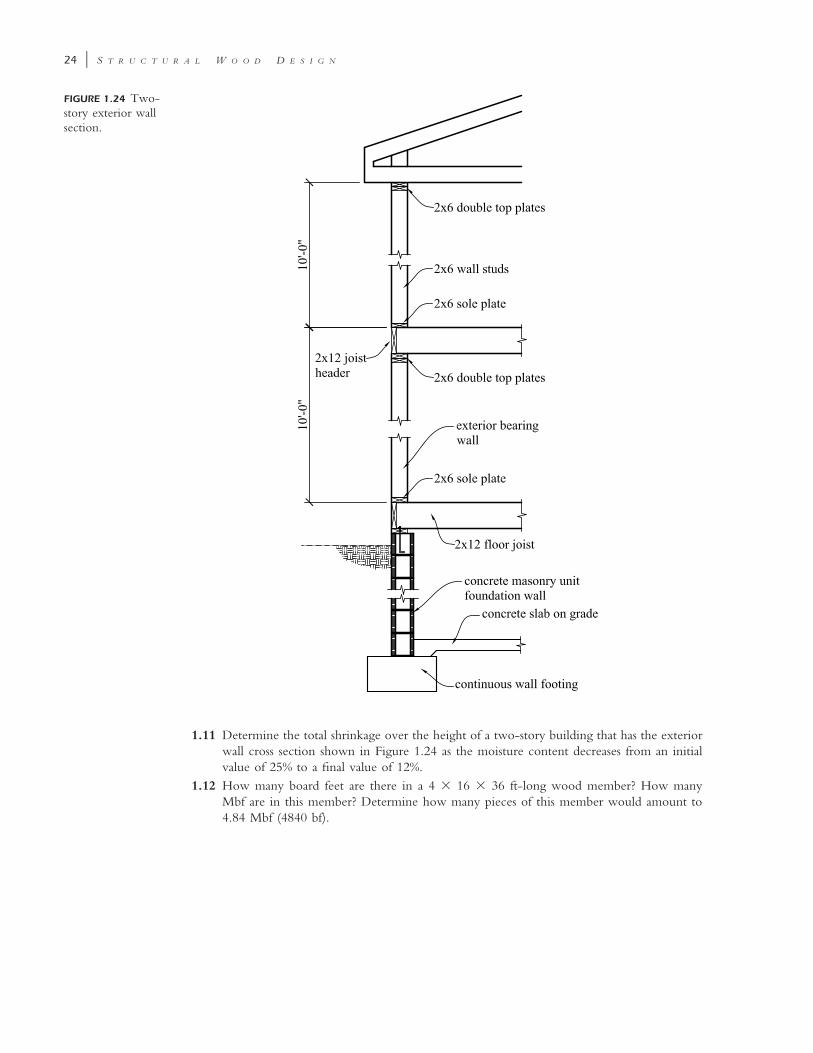
FIGURE 1.24 Two-story exterior wallsection.
1.11 Determine the total shrinkage over the height of a two-story building that has the exteriorwall cross section shown in Figure 1.24 as the moisture content decreases from an initialvalue of 25% to a final value of 12%.
1.12 How many board feet are there in a 4 � 16 � 36 ft-long wood member? How manyMbf are in this member? Determine how many pieces of this member would amount to4.84 Mbf (4840 bf).