introduction to vhdl simulation … synthesis …. the digital design process… initial...
TRANSCRIPT
Introduction to VHDLSimulation …Synthesis …

The digital design process…
Initial specification
Block diagram
Final product
Circuit equations
Logic design
Physical implementation
High-level design
Iterations due to errors

Hardware Description Languages
• Traditionally, different ‘languages’ are used at each stage of the design process (text, diagrams, tables, equations, etc)
• Also, different manufacturers (and CAD tools) use different formats
• Languages should support Specification – Synthesis – Simulation

VHDL
• Originally developed for US DoD (c.1980)• Standardised by IEEE in 1987
• Intended to support all stages of digital design (high-level, logic, netlist)
• Now widely used for synthesis
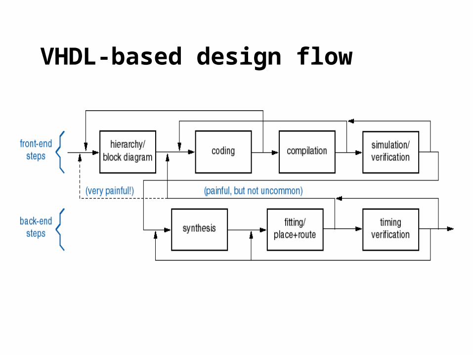
VHDL-based design flow

VHDL entity and architecture concept
• System is a collection of modules.
• Architecture: detailed description of the internal structure or behavior of a module.
• Entity: a “wrapper” for the architecture that exposes only its external interfaces, hiding the internal details.

VHDL program file structure
• Entity and architecture definitions for different modules can be in different files.
– Compiler maintains “work” library and keeps track of definitions using entity and architecture names.

Entity and architecture(s) example ENTITY example_1 IS
PORT ( -- port declarations a, b, c : IN BIT; f : OUT BIT; ); END example_1;
ARCHITECTURE ex1_funct OF example_1 IS
BEGIN -- behavioural description F <= (a OR b) AND c AFTER 5 nS; END ex1_funct;
ARCHITECTURE ex1_struct OF example_1 IS
-- component declarations COMPONENT and_gate PORT(a1,a2: IN BIT; a3: OUT BIT); END COMPONENT; COMPONENT or_gate PORT(o1,o2: IN BIT; o3: OUT BIT); END COMPONENT;
-- local signal declaration SIGNAL d : BIT;
BEGIN -- structural description g1: or_gate PORT MAP(a,b,d); g2: and_gate PORT MAP(c,d,f); END ex1_struct;
Note that either architecture may be used
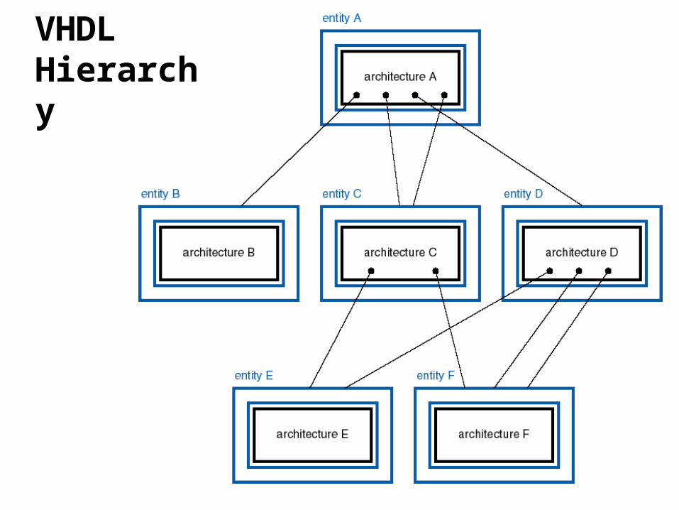
VHDL Hierarchy
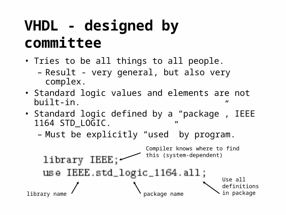
VHDL - designed by committee
• Tries to be all things to all people.– Result - very general, but also very complex.
• Standard logic values and elements are not built-in.
• Standard logic defined by a “package”, IEEE 1164 STD_LOGIC.– Must be explicitly “used” by program.
library name package name
Use all definitions in package
Compiler knows where to find this (system-dependent)

Standard logic values -- not just 0,1• Need additional values for simulation of - three-state
logic, pull-ups, etc.
VHDL strong typing
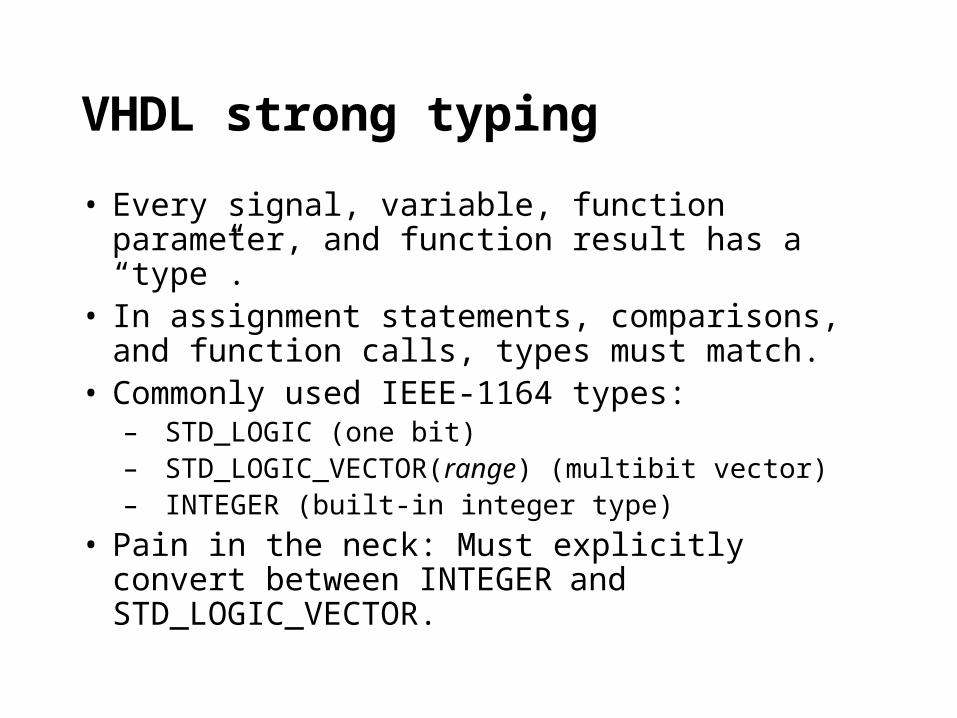
• Every signal, variable, function parameter, and function result has a “type”.
• In assignment statements, comparisons, and function calls, types must match.
• Commonly used IEEE-1164 types:– STD_LOGIC (one bit)– STD_LOGIC_VECTOR(range) (multibit vector)– INTEGER (built-in integer type)
• Pain in the neck: Must explicitly convert between INTEGER and STD_LOGIC_VECTOR.

VHDL programming styles
• Behavioral– Write an algorithm that describes the circuit’s output
– May not be synthesizable or may lead to a very large circuit
– Primarily used for simulation
• Dataflow– assign expressions to signals
– Includes “when” and “select” (case) statements
• Structural– Define explicit components and the connections between them.
– Textual equivalent of drawing a schematic

Example: 2-to-4 decoder
Entity

Architecture
built-in librarycomponents
positionalcorrespondencewith entity definition

Dataflow-style program for 74x138 3-to-8 decoder
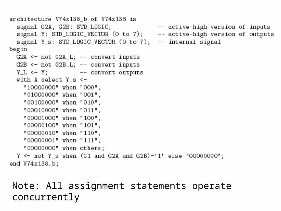
Note: All assignment statements operate concurrently

Behavioral program style
• Normally uses VHDL “processes”• Each VHDL process executes in parallel with
other VHDL processes and concurrent statements• “Concurrent” statements include assignment and
select statements in dataflow-style programs• Concurrency is needed to model the behavior of
parallel, interconnected hardware elements• But “sequential” statements can be used within a
process

VHDL process
• A sequence of “sequential statements”.
• Activated when any signal in the “sensitivity list” changes.

Sequential statements
• assignment• if-then-else• infinite loop• for loop• while loop• case
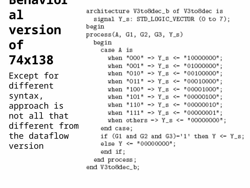
Behavioralversion of74x138
Except for different syntax, approach is not all that different from the dataflow version

Sequential circuits in VHDL
• Edge-triggered D flip-flop with clear

Other models for the same flip-flop
• Synthesis software may only recognize one or two of the possible models of edge triggering, and map these to known flip-flop elements
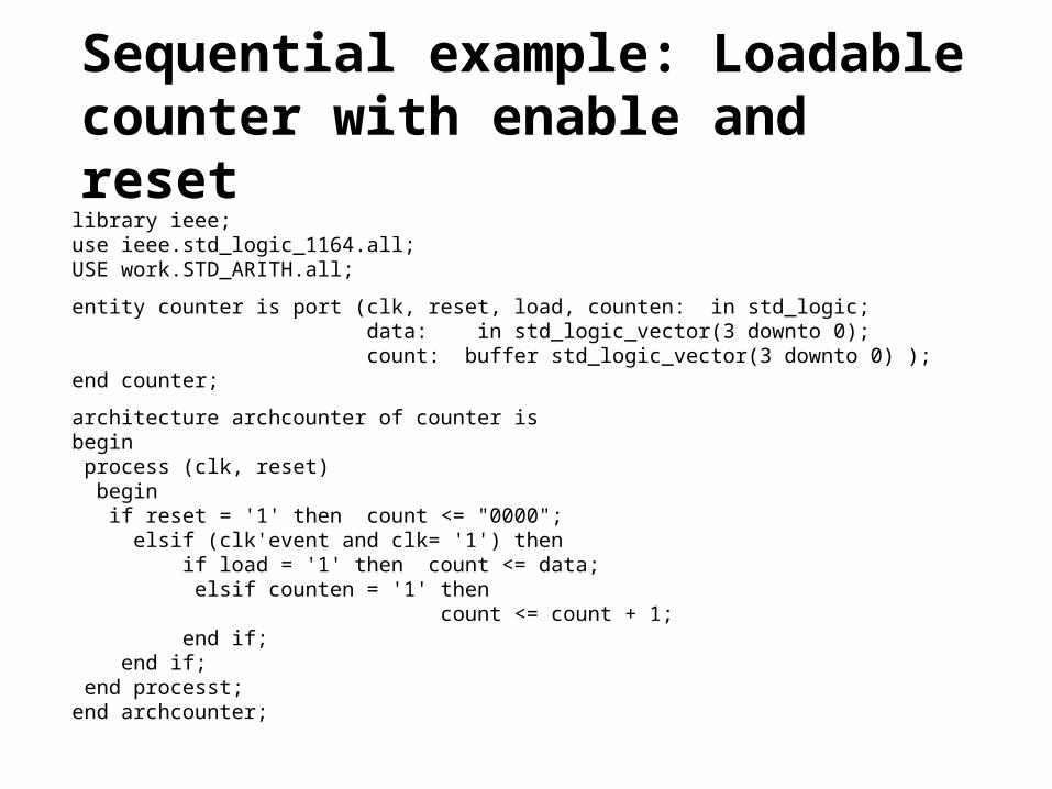
Sequential example: Loadable counter with enable and resetlibrary ieee;use ieee.std_logic_1164.all;USE work.STD_ARITH.all;
entity counter is port (clk, reset, load, counten: in std_logic; data: in std_logic_vector(3 downto 0); count: buffer std_logic_vector(3 downto 0) );end counter;
architecture archcounter of counter isbegin process (clk, reset) begin if reset = '1' then count <= "0000"; elsif (clk'event and clk= '1') then if load = '1' then count <= data; elsif counten = '1' then count <= count + 1; end if; end if; end processt;end archcounter;
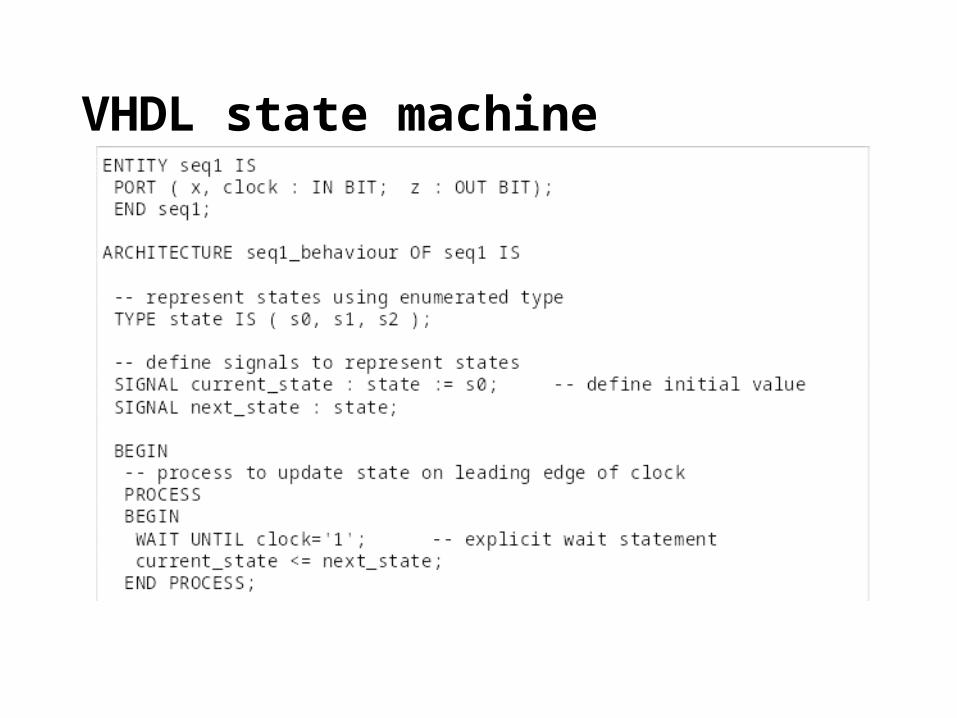
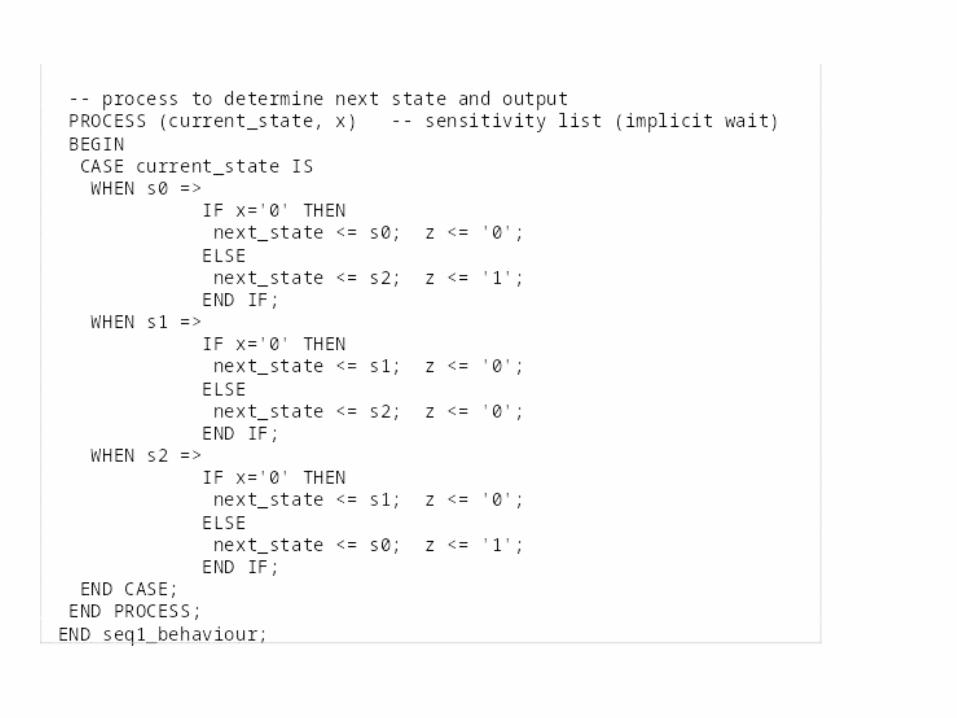
VHDL state machine

VHDL Synthesis
• Synthesis tools will generate circuit equations, state assignment, logic minimisation, etc- but may need additional input from user (pin assignments, speed/area optimisation, etc)
• Tools may require VHDL written in a certain style• The target device must contain the resources
required by the VHDL description• Not all VHDL can be synthesised

VHDL resources
• There are many sources of reference information, examples, ‘cookbooks’, etc
• Text books• Web sites• Computer-based reference manuals/examples