introduction to numerical control (nc) machines · constructional features of cnc the tool / work...
TRANSCRIPT

Introduction toIntroduction toNumerical Control (NC)Numerical Control (NC)
MachinesMachines
V.Gunasegaran, Assistant Professor, Department of Mechanical Engineering, BSACIST, Chennai - 48
V.GunasegaranV.GunasegaranAssistant Professor
Department of Mechanical EngineeringSchool of Mechanical Sciences
BSAU, Chennai - 48

Conventional Lathe machineConventional Lathe machine
V.Gunasegaran, Assistant Professor, Department of Mechanical Engineering, BSACIST, Chennai - 48

Conventional Milling machineConventional Milling machine
V.Gunasegaran, Assistant Professor, Department of Mechanical Engineering, BSACIST, Chennai - 48
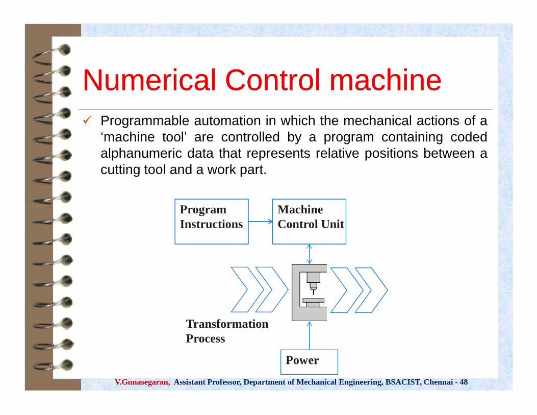
Numerical Control machineNumerical Control machine Programmable automation in which the mechanical actions of a
‘machine tool’ are controlled by a program containing codedalphanumeric data that represents relative positions between acutting tool and a work part.
MachineControl UnitMachineControl Unit
ProgramInstructionsProgramInstructions
V.Gunasegaran, Assistant Professor, Department of Mechanical Engineering, BSACIST, Chennai - 48
MachineControl UnitMachineControl Unit
PowerPower
ProgramInstructionsProgramInstructions
TransformationProcess

Difference betweenDifference betweenConventional m/c & NC m/cConventional m/c & NC m/c
ItemItem ConventionalConventionalmachinemachine
NCNCmachinemachine
1. Movement Acme screw Ball screw
V.Gunasegaran, Assistant Professor, Department of Mechanical Engineering, BSACIST, Chennai - 48
1. Movement Acme screw Ball screw
2. Feed manual motor
3.measurement manual Linear scale

Control SystemControl System
V.Gunasegaran, Assistant Professor, Department of Mechanical Engineering, BSACIST, Chennai - 48

Open and Closed loopOpen and Closed loop
V.Gunasegaran, Assistant Professor, Department of Mechanical Engineering, BSACIST, Chennai - 48

Direct Numerical ControlDirect Numerical ControlDirect numerical control (DNC) – control
of multiple machine tools by a single(mainframe) computer through directconnection and in real time– 1960s technology– Two way communication
V.Gunasegaran, Assistant Professor, Department of Mechanical Engineering, BSACIST, Chennai - 48
Direct numerical control (DNC) – controlof multiple machine tools by a single(mainframe) computer through directconnection and in real time– 1960s technology– Two way communication

DNCDNC –– contd.,contd.,
CentralComputerCentralComputer NC Prgrm
Computer Network
V.Gunasegaran, Assistant Professor, Department of Mechanical Engineering, BSACIST, Chennai - 48
MachineControl Unit
1
MachineControl Unit
1
TransformationProcess
MachineControl Unit
2
MachineControl Unit
2
MachineControl Unit
3
MachineControl Unit
3

Computer NumericalComputer NumericalControl (CNC) MachinesControl (CNC) Machines
V.Gunasegaran, Assistant Professor, Department of Mechanical Engineering, BSACIST, Chennai - 48
Computer NumericalComputer NumericalControl (CNC) MachinesControl (CNC) Machines

Basic CNC PrincipleBasic CNC Principle
V.Gunasegaran, Assistant Professor, Department of Mechanical Engineering, BSACIST, Chennai - 48
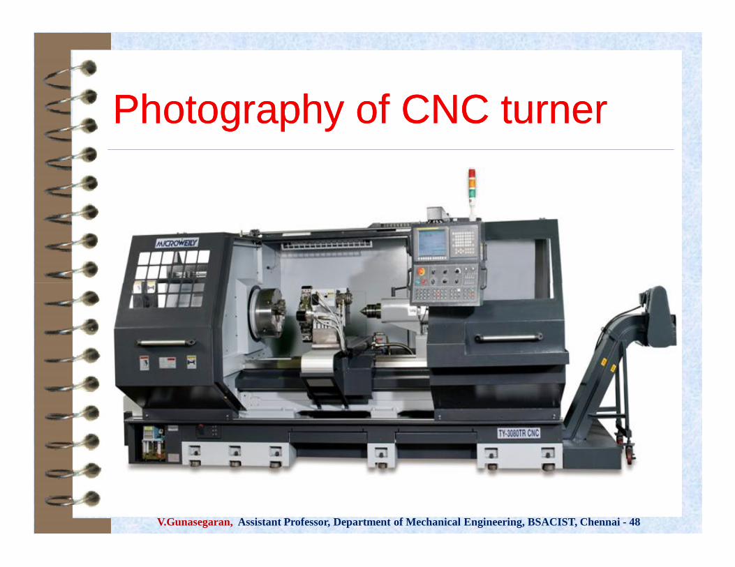
Photography of CNC turnerPhotography of CNC turner
V.Gunasegaran, Assistant Professor, Department of Mechanical Engineering, BSACIST, Chennai - 48

Photography of CNC millerPhotography of CNC miller
V.Gunasegaran, Assistant Professor, Department of Mechanical Engineering, BSACIST, Chennai - 48

Motion Control methodsMotion Control methodsPoint-to-Point systems Also called position systems System moves to a location and performs an
operation at that location (e.g., drilling) Also applicable in robotics
Continuous path systems Also called contouring systems in machining System performs an operation during movement
(e.g., milling and turning)
V.Gunasegaran, Assistant Professor, Department of Mechanical Engineering, BSACIST, Chennai - 48
Point-to-Point systems Also called position systems System moves to a location and performs an
operation at that location (e.g., drilling) Also applicable in robotics
Continuous path systems Also called contouring systems in machining System performs an operation during movement
(e.g., milling and turning)

Interpolation methodsInterpolation methods1. Linear interpolation
– Straight line between two points inspace
2. Circular interpolation– Circular arc defined by starting point,
end point, center or radius, anddirection
3. Helical interpolation– Circular plus linear motion
4. Parabolic and cubic interpolation– Free form curves using higher order
equations
V.Gunasegaran, Assistant Professor, Department of Mechanical Engineering, BSACIST, Chennai - 48
1. Linear interpolation– Straight line between two points in
space2. Circular interpolation
– Circular arc defined by starting point,end point, center or radius, anddirection
3. Helical interpolation– Circular plus linear motion
4. Parabolic and cubic interpolation– Free form curves using higher order
equations

Absolute vs. Incremental PositioningAbsolute vs. Incremental Positioning Absolute positioning
Move is: x = 40, y = 50
Incremental positioningMove is: x = 20, y = 30
V.Gunasegaran, Assistant Professor, Department of Mechanical Engineering, BSACIST, Chennai - 48
Absolute positioningMove is: x = 40, y = 50
Incremental positioningMove is: x = 20, y = 30

Coordinate SystemsCoordinate SystemsFor flat and prismatic (block-like) parts: Milling and drilling operations Conventional Cartesian coordinate system Rotational axis about each linear axis
For rotational parts: Turning operations Only x- and z-axis
V.Gunasegaran, Assistant Professor, Department of Mechanical Engineering, BSACIST, Chennai - 48
For flat and prismatic (block-like) parts: Milling and drilling operations Conventional Cartesian coordinate system Rotational axis about each linear axis
For rotational parts: Turning operations Only x- and z-axis
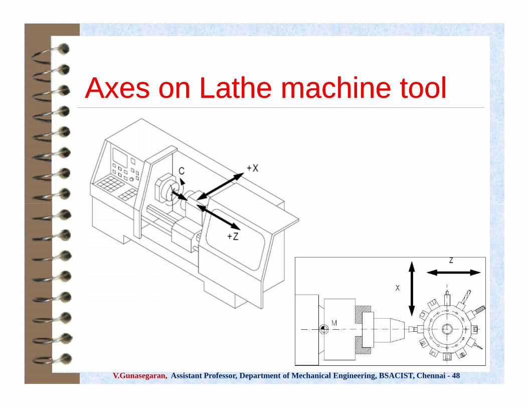
Axes on Lathe machine toolAxes on Lathe machine tool
V.Gunasegaran, Assistant Professor, Department of Mechanical Engineering, BSACIST, Chennai - 48

Contd.,Contd.,
V.Gunasegaran, Assistant Professor, Department of Mechanical Engineering, BSACIST, Chennai - 48

Axes on Milling machine toolAxes on Milling machine tool
V.Gunasegaran, Assistant Professor, Department of Mechanical Engineering, BSACIST, Chennai - 48

Contd.,Contd.,
V.Gunasegaran, Assistant Professor, Department of Mechanical Engineering, BSACIST, Chennai - 48

ClassificationsClassifications Based on Machine centre:
Turn mill centre / Vertical mill centre Based on Motion Type:
Point-to-Point / Continuous path Based on Control Loops:
Open loop / Closed loop Based on Input power:
Electric / Hydraulic / Pneumatic Based on Positioning System
Incremental / AbsoluteV.Gunasegaran, Assistant Professor, Department of Mechanical Engineering, BSACIST, Chennai - 48
Based on Machine centre:Turn mill centre / Vertical mill centre
Based on Motion Type:Point-to-Point / Continuous path
Based on Control Loops:Open loop / Closed loop
Based on Input power:Electric / Hydraulic / Pneumatic
Based on Positioning SystemIncremental / Absolute

Constructional features of CNCConstructional features of CNC The tool / work part (table) moves Tools can operate in 1-5 axes Larger machines have a machine control unit (MCU)
which manages operations Movement is controlled by servo motors (actuators) Feedback is provided by sensors (transducers) Tool magazines are used to change the tools
automatically Relative movement of the tool with respect to
workpiece or vice versa can be guided andcontrolled by a Part program
V.Gunasegaran, Assistant Professor, Department of Mechanical Engineering, BSACIST, Chennai - 48
The tool / work part (table) moves Tools can operate in 1-5 axes Larger machines have a machine control unit (MCU)
which manages operations Movement is controlled by servo motors (actuators) Feedback is provided by sensors (transducers) Tool magazines are used to change the tools
automatically Relative movement of the tool with respect to
workpiece or vice versa can be guided andcontrolled by a Part program

Feed control systemFeed control system
V.Gunasegaran, Assistant Professor, Department of Mechanical Engineering, BSACIST, Chennai - 48

Machine Control UnitMachine Control Unit
V.Gunasegaran, Assistant Professor, Department of Mechanical Engineering, BSACIST, Chennai - 48

Components and its FunctionsComponents and its Functions
On board computerFeed driveMeasuring systemWork spindle / Work tableCooling systemTool magazine (Turret)
V.Gunasegaran, Assistant Professor, Department of Mechanical Engineering, BSACIST, Chennai - 48
On board computerFeed driveMeasuring systemWork spindle / Work tableCooling systemTool magazine (Turret)
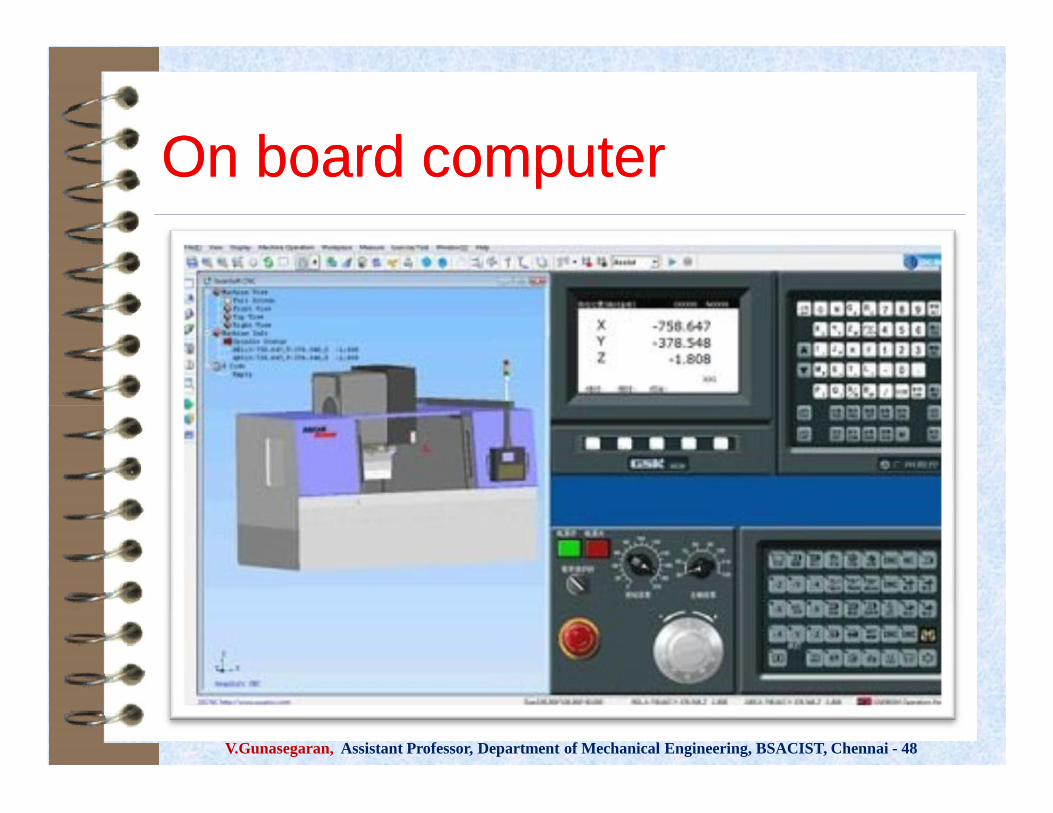
On board computerOn board computer
V.Gunasegaran, Assistant Professor, Department of Mechanical Engineering, BSACIST, Chennai - 48

Feed driveFeed drive
~
S e r v o C o n t r o l le r
C o u n t e r C o m p a r a t o r
E n c o d e r A / C M o t o r
I n p u t ( c o n v e r t e d f r o m a n a lo g t o d ig i t a l v a lu e )
T a b leL e a d s c r e w
V.Gunasegaran, Assistant Professor, Department of Mechanical Engineering, BSACIST, Chennai - 48
~
S e r v o C o n t r o l le r
C o u n t e r C o m p a r a t o r
E n c o d e r A / C M o t o r
I n p u t ( c o n v e r t e d f r o m a n a lo g t o d ig i t a l v a lu e )
T a b leL e a d s c r e w

Recirculating ball mechanismRecirculating ball mechanism
V.Gunasegaran, Assistant Professor, Department of Mechanical Engineering, BSACIST, Chennai - 48

Measuring SystemMeasuring SystemDirect Position measuring
V.Gunasegaran, Assistant Professor, Department of Mechanical Engineering, BSACIST, Chennai - 48
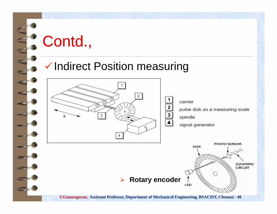
Contd.,Contd., Indirect Position measuring
V.Gunasegaran, Assistant Professor, Department of Mechanical Engineering, BSACIST, Chennai - 48
Rotary encoder

Work SpindleWork Spindle
V.Gunasegaran, Assistant Professor, Department of Mechanical Engineering, BSACIST, Chennai - 48

Work tableWork table
V.Gunasegaran, Assistant Professor, Department of Mechanical Engineering, BSACIST, Chennai - 48

Cooling SystemCooling System
V.Gunasegaran, Assistant Professor, Department of Mechanical Engineering, BSACIST, Chennai - 48

Tool MagazineTool Magazine
Single Turret
V.Gunasegaran, Assistant Professor, Department of Mechanical Engineering, BSACIST, Chennai - 48
Chain Turret

CNC Part ProgrammingCNC Part Programming Part program is a sequential set of
instructions Storage of more than one part program Various forms of program input Program editing at the machine tool (on
board computer ) Fixed cycles and programming subroutines Communications interface
V.Gunasegaran, Assistant Professor, Department of Mechanical Engineering, BSACIST, Chennai - 48
Part program is a sequential set ofinstructions
Storage of more than one part program Various forms of program input Program editing at the machine tool (on
board computer ) Fixed cycles and programming subroutines Communications interface

Benefits of CNCBenefits of CNCCycle time reductionNonproductive time reductionGreater accuracy and repeatationLower scrap ratesReduced parts inventory and floor
spaceOperator skill-level reduced
V.Gunasegaran, Assistant Professor, Department of Mechanical Engineering, BSACIST, Chennai - 48
Cycle time reductionNonproductive time reductionGreater accuracy and repeatationLower scrap ratesReduced parts inventory and floor
spaceOperator skill-level reduced

Limitations of CNCLimitations of CNC
High machine costComplicated maintenanceSkill & training are required for
programming and maintenanceHigh tooling costTemperature, humidity & dust must be
controlled
V.Gunasegaran, Assistant Professor, Department of Mechanical Engineering, BSACIST, Chennai - 48
High machine costComplicated maintenanceSkill & training are required for
programming and maintenanceHigh tooling costTemperature, humidity & dust must be
controlled
CNC Application CharacteristicsCNC Application Characteristics
Batch and High Volume production Repeat and/or Repetitive orders Geometry and dimensional accuracy Good surface finish Complex part geometries Many separate operations on one part
V.Gunasegaran, Assistant Professor, Department of Mechanical Engineering, BSACIST, Chennai - 48
Batch and High Volume production Repeat and/or Repetitive orders Geometry and dimensional accuracy Good surface finish Complex part geometries Many separate operations on one part

Applications of CNCApplications of CNC
V.Gunasegaran, Assistant Professor, Department of Mechanical Engineering, BSACIST, Chennai - 48

CNC PARTCNC PARTPROGRAMMINGPROGRAMMING
V.Gunasegaran, Assistant Professor, Department of Mechanical Engineering, BSACIST, Chennai - 48
CNC PARTCNC PARTPROGRAMMINGPROGRAMMING

IntroductionIntroduction Part Programme is a set of instructions which
instructs the machine tool about the processingsteps to be performed for the manufacturing acomponent
Part programme is an important part of the CNCsystem
The shape of manufactured components willdepends on how correctly the programme hasbeen prepared
The part programme is transferred to as one ofthe input medium which instruct the CNCmachine
V.Gunasegaran, Assistant Professor, Department of Mechanical Engineering, BSACIST, Chennai - 48
Part Programme is a set of instructions whichinstructs the machine tool about the processingsteps to be performed for the manufacturing acomponent
Part programme is an important part of the CNCsystem
The shape of manufactured components willdepends on how correctly the programme hasbeen prepared
The part programme is transferred to as one ofthe input medium which instruct the CNCmachine

Types of programmingTypes of programming NC coding Manual part programming Automatic Part Programming
Languages:– APT– UNIAPT– COMPACT II– FORTRAN
V.Gunasegaran, Assistant Professor, Department of Mechanical Engineering, BSACIST, Chennai - 48
NC coding Manual part programming Automatic Part Programming
Languages:– APT– UNIAPT– COMPACT II– FORTRAN

Manual Part ProgrammingManual Part Programming Binary code decimal system (BCDS) Bit - 0 or 1 => absence or presence of hole in
the tape which is in MCU Character - row of bits across the tape
(smallest unit / digit)Word - sequence of characters (combination
of alpha-numerical characters) Block - collection of words to form one
complete instruction (logical order of processing)
Part program - sequence of instructionsV.Gunasegaran, Assistant Professor, Department of Mechanical Engineering, BSACIST, Chennai - 48
Binary code decimal system (BCDS) Bit - 0 or 1 => absence or presence of hole in
the tape which is in MCU Character - row of bits across the tape
(smallest unit / digit)Word - sequence of characters (combination
of alpha-numerical characters) Block - collection of words to form one
complete instruction (logical order of processing)
Part program - sequence of instructions

Block FormatBlock Format The organization of words within a block in NC part
program Word address format - used on all modern CNC
controllers– Uses a letter prefix to identify each type of word– Spaces to separate words within the block– Allows any order of words in a block– Words can be omitted if their values do not
change from the previous block– A new blocks can be inserted between two
existing blocks
V.Gunasegaran, Assistant Professor, Department of Mechanical Engineering, BSACIST, Chennai - 48
The organization of words within a block in NC partprogram
Word address format - used on all modern CNCcontrollers– Uses a letter prefix to identify each type of word– Spaces to separate words within the block– Allows any order of words in a block– Words can be omitted if their values do not
change from the previous block– A new blocks can be inserted between two
existing blocks

Example FormatExample Format
V.Gunasegaran, Assistant Professor, Department of Mechanical Engineering, BSACIST, Chennai - 48
Instruction CodesInstruction CodesA part program consists the following words:
N, G, X, Y, Z, I, J, K, F, S, T, R, MN - sequence number prefix (to identify the block)G - preparatory functions (to prepare the controller)
– Example: G00 - rapid transverse move
X, Y, Z - prefixes for x, y, and z-axes (position & motion )I, J, K – Interpolation parametersF - feed rate (to specify the feed)S - spindle speed (to specify the seed)T - tool selection (for ATC only)R – arc radius (to specify the tool radius in drill cycles)M - miscellaneous functions (to specify auxiliary functions)
– Example: M08 = turn cutting fluid onV.Gunasegaran, Assistant Professor, Department of Mechanical Engineering, BSACIST, Chennai - 48
A part program consists the following words:N, G, X, Y, Z, I, J, K, F, S, T, R, M
N - sequence number prefix (to identify the block)G - preparatory functions (to prepare the controller)
– Example: G00 - rapid transverse move
X, Y, Z - prefixes for x, y, and z-axes (position & motion )I, J, K – Interpolation parametersF - feed rate (to specify the feed)S - spindle speed (to specify the seed)T - tool selection (for ATC only)R – arc radius (to specify the tool radius in drill cycles)M - miscellaneous functions (to specify auxiliary functions)
– Example: M08 = turn cutting fluid on

Elements of Part programElements of Part program Preparatory functions: which unit, which interpolator,
absolute or incremental programming, which circularinterpolation plane, cutter compensation, etc.,
Coordinates: 3 translational and 3 rotational axis Machining parameters: feed, and speed Tool control: next tool number, tool change Cycle functions: canned cycle, drill cycle, ream
cycle, bore cycle, mill cycle Miscellaneous functions: coolant on/off, spindle
on/off, programme rewind, spindle rotation direction,etc.,
V.Gunasegaran, Assistant Professor, Department of Mechanical Engineering, BSACIST, Chennai - 48
Preparatory functions: which unit, which interpolator,absolute or incremental programming, which circularinterpolation plane, cutter compensation, etc.,
Coordinates: 3 translational and 3 rotational axis Machining parameters: feed, and speed Tool control: next tool number, tool change Cycle functions: canned cycle, drill cycle, ream
cycle, bore cycle, mill cycle Miscellaneous functions: coolant on/off, spindle
on/off, programme rewind, spindle rotation direction,etc.,

GG--CodesCodes
V.Gunasegaran, Assistant Professor, Department of Mechanical Engineering, BSACIST, Chennai - 48

MM--CodesCodes
V.Gunasegaran, Assistant Professor, Department of Mechanical Engineering, BSACIST, Chennai - 48
Machine and Tool offsetMachine and Tool offset Difficult to place a vise in the exact same position on the
machine each time The distance from home to the WCS is usually not
known until the vise is set and aligned with the machine Different tools extend out from the machine spindle with
different lengths If the tool wears or breaks, tool must be replaced, it is
almost impossible to set it the exact length out of thetool holder each time
Therefore, there must be some way to relate the (MCS)machine coordinate system to the WCS and take intoaccount varying tool lengths
This is done using reference pointsV.Gunasegaran, Assistant Professor, Department of Mechanical Engineering, BSACIST, Chennai - 48
Difficult to place a vise in the exact same position on themachine each time
The distance from home to the WCS is usually notknown until the vise is set and aligned with the machine
Different tools extend out from the machine spindle withdifferent lengths
If the tool wears or breaks, tool must be replaced, it isalmost impossible to set it the exact length out of thetool holder each time
Therefore, there must be some way to relate the (MCS)machine coordinate system to the WCS and take intoaccount varying tool lengths
This is done using reference points

Reference PointsReference PointsMachine Origin The machine origin is a fixed point set by the
machine tool builder
Usually it cannot be changed
Any tool movement is measured from this point
The controller always remembers tool distancefrom the machine origin
V.Gunasegaran, Assistant Professor, Department of Mechanical Engineering, BSACIST, Chennai - 48
Machine Origin The machine origin is a fixed point set by the
machine tool builder
Usually it cannot be changed
Any tool movement is measured from this point
The controller always remembers tool distancefrom the machine origin

Contd.,Contd.,Program Origin It is also called home position of the tool
Program origin is point from where the tool startsfor its motion while executing a program andreturns back at the end of the cycle
This can be any point within the workspace of thetool which is sufficiently away from the part
V.Gunasegaran, Assistant Professor, Department of Mechanical Engineering, BSACIST, Chennai - 48
Program Origin It is also called home position of the tool
Program origin is point from where the tool startsfor its motion while executing a program andreturns back at the end of the cycle
This can be any point within the workspace of thetool which is sufficiently away from the part

Contd.,Contd.,Part Origin The part origin can be set at any point inside the
machine's electronic grid system
Establishing the part origin is also known as zeroshift, work shift, floating zero or datum
Usually part origin needs to be defined for eachnew setup
Zero shifting allows the relocation of the part
Sometimes the part accuracy is affected by thelocation of the part origin
V.Gunasegaran, Assistant Professor, Department of Mechanical Engineering, BSACIST, Chennai - 48
Part Origin The part origin can be set at any point inside the
machine's electronic grid system
Establishing the part origin is also known as zeroshift, work shift, floating zero or datum
Usually part origin needs to be defined for eachnew setup
Zero shifting allows the relocation of the part
Sometimes the part accuracy is affected by thelocation of the part origin

Contd.,Contd.,
V.Gunasegaran, Assistant Professor, Department of Mechanical Engineering, BSACIST, Chennai - 48

Contd.,Contd.,
V.Gunasegaran, Assistant Professor, Department of Mechanical Engineering, BSACIST, Chennai - 48
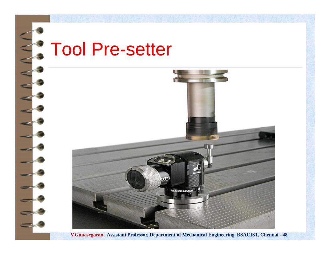
Tool PreTool Pre--settersetter
V.Gunasegaran, Assistant Professor, Department of Mechanical Engineering, BSACIST, Chennai - 48

Structure of programStructure of program
V.Gunasegaran, Assistant Professor, Department of Mechanical Engineering, BSACIST, Chennai - 48

Exercise:Exercise: 11 (Drilling)(Drilling)
30m
m
30 mm
Write a CNC part program to drill twoholes of diameter 10 mm in a 5mm thickmild steel plate as shown in fig.
(Diagram not to scale)
V.Gunasegaran, Assistant Professor, Department of Mechanical Engineering, BSACIST, Chennai - 48
90m
m
90 mm
30m
m
30 mm
30m
m

Location of Reference pointLocation of Reference point
V.Gunasegaran, Assistant Professor, Department of Mechanical Engineering, BSACIST, Chennai - 48

Process planProcess plan
V.Gunasegaran, Assistant Professor, Department of Mechanical Engineering, BSACIST, Chennai - 48

Part ProgramPart ProgramBlock 1: O0001;
Block 2: N01 G17 G21 G80 G90 G94;
Block 3: N02 G00 X0, Y0, Z10;
Block 4: N03 X30, Y30;
Block 5: N04 G01 X70 Y30 S800 M03;
Block 6: N05 Z-7 F0.3 M08;
Block 7: N06 Z2;
Block 8: N07 G00 Y60;
Block 9: N08 G01 Z-7 F0.3;
Block 10: N09 Z2;
Block 11: N10 G00 X0 Y0 Z10 M05 M09;
Block 12: N10 M02;V.Gunasegaran, Assistant Professor, Department of Mechanical Engineering, BSACIST, Chennai - 48
Block 1: O0001;
Block 2: N01 G17 G21 G80 G90 G94;
Block 3: N02 G00 X0, Y0, Z10;
Block 4: N03 X30, Y30;
Block 5: N04 G01 X70 Y30 S800 M03;
Block 6: N05 Z-7 F0.3 M08;
Block 7: N06 Z2;
Block 8: N07 G00 Y60;
Block 9: N08 G01 Z-7 F0.3;
Block 10: N09 Z2;
Block 11: N10 G00 X0 Y0 Z10 M05 M09;
Block 12: N10 M02;

Canned CycleCanned Cycle
V.Gunasegaran, Assistant Professor, Department of Mechanical Engineering, BSACIST, Chennai - 48
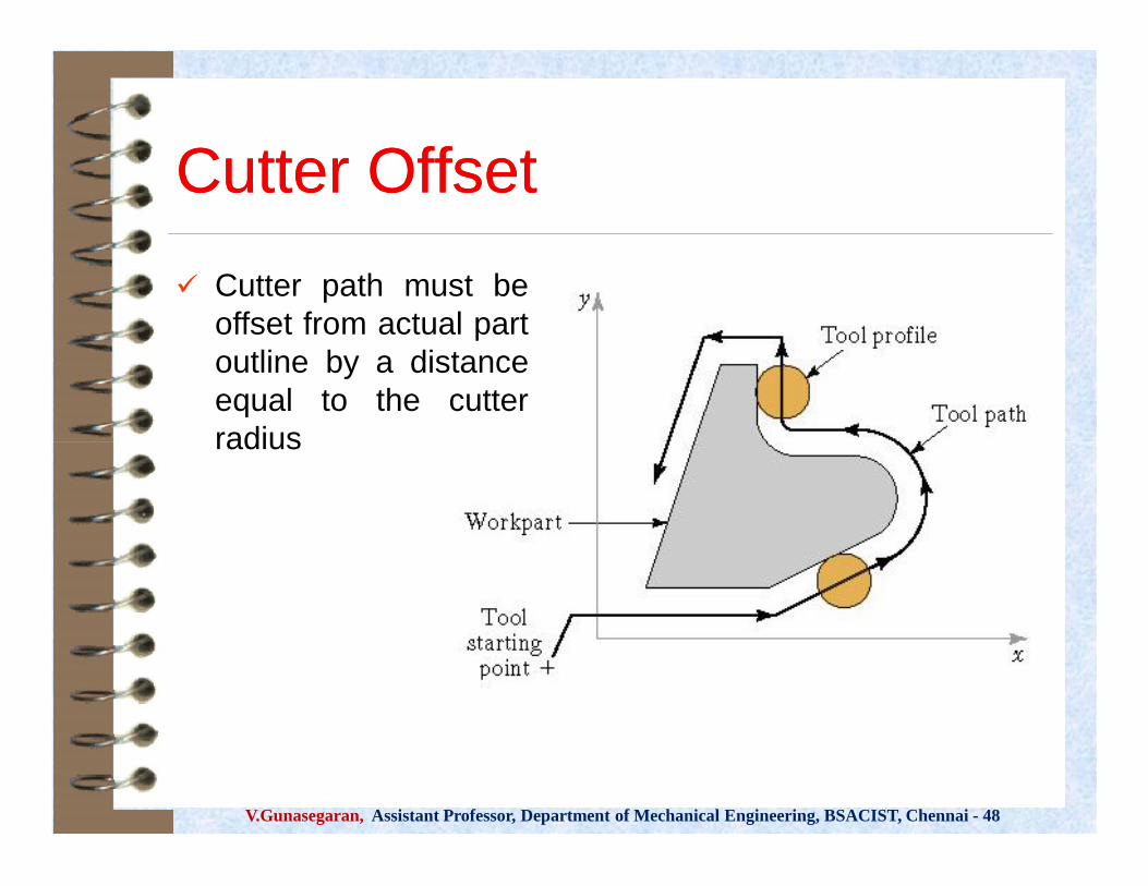
Cutter OffsetCutter Offset Cutter path must be
offset from actual partoutline by a distanceequal to the cutterradius
V.Gunasegaran, Assistant Professor, Department of Mechanical Engineering, BSACIST, Chennai - 48
Cutter path must beoffset from actual partoutline by a distanceequal to the cutterradius

Write the part program for drilling holes in the mild steel plate ofthickness 20 mm as shown in figure 1 (diagram not to scale) andassume the parameters such as speed, feed, depth of cut etc.
V.Gunasegaran, Assistant Professor, Department of Mechanical Engineering, BSACIST, Chennai - 48

Exercise 2Exercise 2
Write an efficient CNC partprogram to drill 35 holes ofdiameter of 0.5 inch eachin a machine component asshown in the figure.
The raw material to beemployed is mild steel plateof 0.4 inch thickness.
V.Gunasegaran, Assistant Professor, Department of Mechanical Engineering, BSACIST, Chennai - 48
Write an efficient CNC partprogram to drill 35 holes ofdiameter of 0.5 inch eachin a machine component asshown in the figure.
The raw material to beemployed is mild steel plateof 0.4 inch thickness.

Part ProgramPart Program
V.Gunasegaran, Assistant Professor, Department of Mechanical Engineering, BSACIST, Chennai - 48

ExplanationExplanationBlock 1:It indicates the start of the program.
Block 2:It specifies the program number and ID. It is usually a alpha-numericalcode and always start with an alphabet ‘O’.
Block 3:It sets the entry of dimensional units in Imperial format.
Block 4:G17: It selects the plane of operation as X-Y planeG40, G80, G49 are used to cancel all usual cycle that might have left inon-mode during the execution of last CNC code.G90 selects the method of specifying dimensions between features as‘absolute’.
V.Gunasegaran, Assistant Professor, Department of Mechanical Engineering, BSACIST, Chennai - 48
Block 1:It indicates the start of the program.
Block 2:It specifies the program number and ID. It is usually a alpha-numericalcode and always start with an alphabet ‘O’.
Block 3:It sets the entry of dimensional units in Imperial format.
Block 4:G17: It selects the plane of operation as X-Y planeG40, G80, G49 are used to cancel all usual cycle that might have left inon-mode during the execution of last CNC code.G90 selects the method of specifying dimensions between features as‘absolute’.

Contd.,Contd.,Block 5:
It sets the program zero on the work part. There are three major environments in programming that require an
established mathematical relationship.Machine: machine tool and control systemPart: Workpiece + Drawing + materialTool: Holder + Cutting tool
The location coordinates of the program zero with respect to themachine reference zero must be communicated with the MCU so thatthe MCU will convert the part program in to required signals to controlthe machine tool.
This can be achieved by using a Preparatory code ‘G92'. The syntax ofG92 is as follows:
G92 X… Y… Z…V.Gunasegaran, Assistant Professor, Department of Mechanical Engineering, BSACIST, Chennai - 48
Block 5: It sets the program zero on the work part. There are three major environments in programming that require an
established mathematical relationship.Machine: machine tool and control systemPart: Workpiece + Drawing + materialTool: Holder + Cutting tool
The location coordinates of the program zero with respect to themachine reference zero must be communicated with the MCU so thatthe MCU will convert the part program in to required signals to controlthe machine tool.
This can be achieved by using a Preparatory code ‘G92'. The syntax ofG92 is as follows:
G92 X… Y… Z…
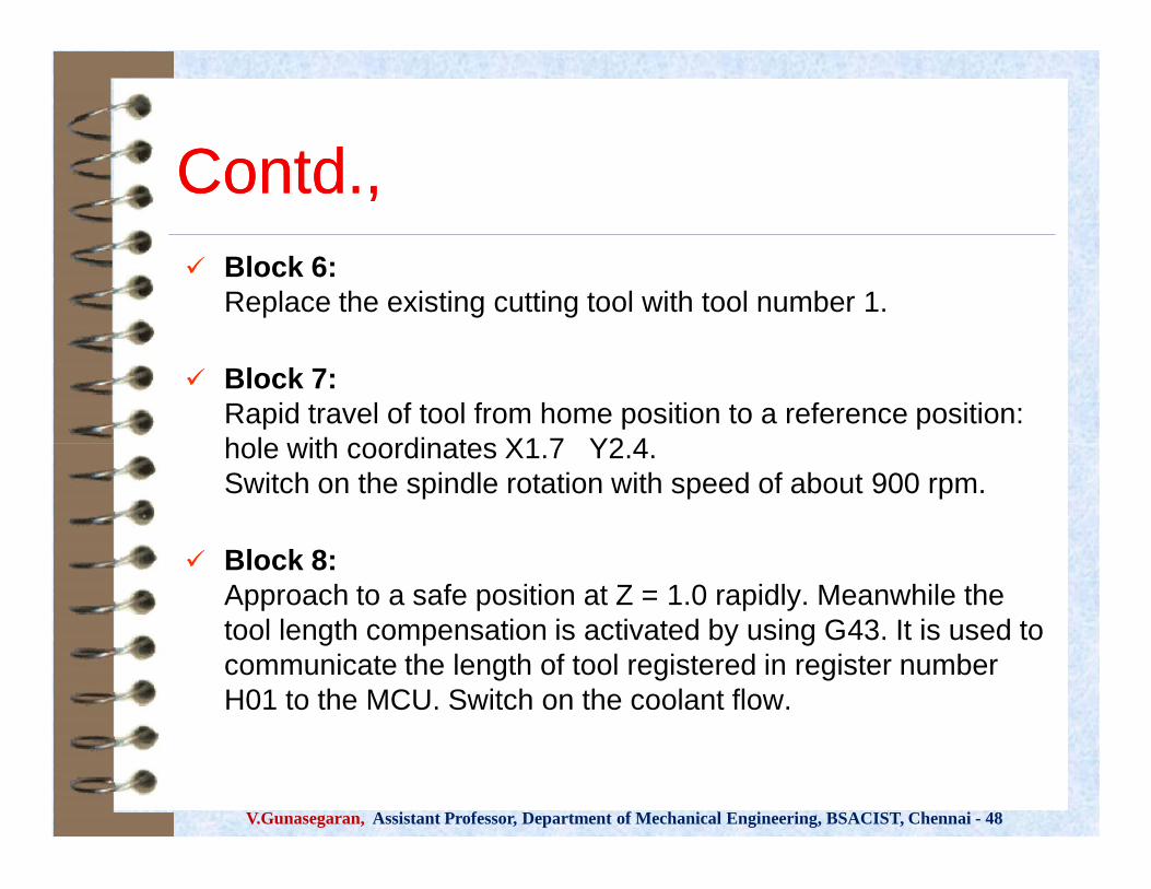
Contd.,Contd., Block 6:
Replace the existing cutting tool with tool number 1.
Block 7:Rapid travel of tool from home position to a reference position:hole with coordinates X1.7 Y2.4.Switch on the spindle rotation with speed of about 900 rpm.
Block 8:Approach to a safe position at Z = 1.0 rapidly. Meanwhile thetool length compensation is activated by using G43. It is used tocommunicate the length of tool registered in register numberH01 to the MCU. Switch on the coolant flow.
V.Gunasegaran, Assistant Professor, Department of Mechanical Engineering, BSACIST, Chennai - 48
Block 6:Replace the existing cutting tool with tool number 1.
Block 7:Rapid travel of tool from home position to a reference position:hole with coordinates X1.7 Y2.4.Switch on the spindle rotation with speed of about 900 rpm.
Block 8:Approach to a safe position at Z = 1.0 rapidly. Meanwhile thetool length compensation is activated by using G43. It is used tocommunicate the length of tool registered in register numberH01 to the MCU. Switch on the coolant flow.

Contd.,Contd.,Block 9:
In the given task, number of holes is to be drilled. For this purpose a special function or cycle is used. It is called
as drilling canned cycle. Its syntax and meaning are shown below. The number of motions/action elements of drilling operations is
specified only at once. Later only the locations of holes to be drilled are given to the
MCU.
V.Gunasegaran, Assistant Professor, Department of Mechanical Engineering, BSACIST, Chennai - 48
Block 9: In the given task, number of holes is to be drilled. For this purpose a special function or cycle is used. It is called
as drilling canned cycle. Its syntax and meaning are shown below. The number of motions/action elements of drilling operations is
specified only at once. Later only the locations of holes to be drilled are given to the
MCU.

Contd.,Contd., Block 10:
It suggests the distance of next location of the hole. It isalso suggested to carry out the same drilling operation 6times along the Y-axis with an increment of 2.1.
Block 11:Drill the hole at increment of 1.8 along X-direction.
Block 12:Carry out the drilling operation 6 times along the Y-axiswith decrement of 2.1.
Block 13:Drill the hole at increment of 1.8 along X-direction.
V.Gunasegaran, Assistant Professor, Department of Mechanical Engineering, BSACIST, Chennai - 48
Block 10:It suggests the distance of next location of the hole. It isalso suggested to carry out the same drilling operation 6times along the Y-axis with an increment of 2.1.
Block 11:Drill the hole at increment of 1.8 along X-direction.
Block 12:Carry out the drilling operation 6 times along the Y-axiswith decrement of 2.1.
Block 13:Drill the hole at increment of 1.8 along X-direction.
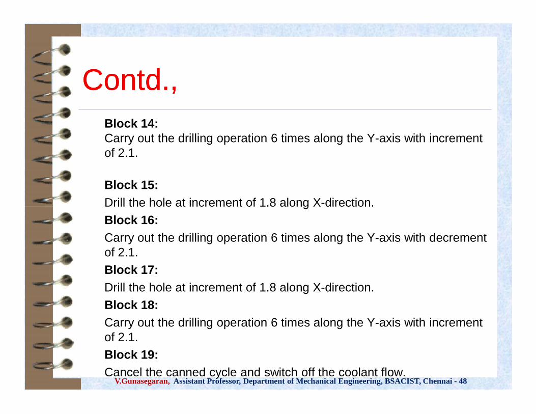
Contd.,Contd.,Block 14:Carry out the drilling operation 6 times along the Y-axis with incrementof 2.1.
Block 15:Drill the hole at increment of 1.8 along X-direction.Block 16:Carry out the drilling operation 6 times along the Y-axis with decrementof 2.1.Block 17:Drill the hole at increment of 1.8 along X-direction.Block 18:Carry out the drilling operation 6 times along the Y-axis with incrementof 2.1.Block 19:Cancel the canned cycle and switch off the coolant flow.
V.Gunasegaran, Assistant Professor, Department of Mechanical Engineering, BSACIST, Chennai - 48
Block 14:Carry out the drilling operation 6 times along the Y-axis with incrementof 2.1.
Block 15:Drill the hole at increment of 1.8 along X-direction.Block 16:Carry out the drilling operation 6 times along the Y-axis with decrementof 2.1.Block 17:Drill the hole at increment of 1.8 along X-direction.Block 18:Carry out the drilling operation 6 times along the Y-axis with incrementof 2.1.Block 19:Cancel the canned cycle and switch off the coolant flow.

Contd.,Contd.,Block 20:Stop the spindle and go to safe position along Zdirection at 0.0.Block 21:Go to home position via X= 0 and Y=0.Block 22:Stop the program from execution.Block 23:End the program.
V.Gunasegaran, Assistant Professor, Department of Mechanical Engineering, BSACIST, Chennai - 48
Block 20:Stop the spindle and go to safe position along Zdirection at 0.0.Block 21:Go to home position via X= 0 and Y=0.Block 22:Stop the program from execution.Block 23:End the program.

Exercise 3 (Turning)Exercise 3 (Turning)
V.Gunasegaran, Assistant Professor, Department of Mechanical Engineering, BSACIST, Chennai - 48

Part programPart program
V.Gunasegaran, Assistant Professor, Department of Mechanical Engineering, BSACIST, Chennai - 48

DefineTool
Automatic part programmingAutomatic part programming
V.Gunasegaran, Assistant Professor, Department of Mechanical Engineering, BSACIST, Chennai - 48
Make 3D model
CNCdata
Simulatecutting

****** All the bestAll the best ******
V.Gunasegaran, Assistant Professor, Department of Mechanical Engineering, BSACIST, Chennai - 48