introduction to fibre optics: part-i
TRANSCRIPT

INTRODUCTION TO
FIBRE OPTICS: PART-I
CONTENTS
• Evolution of fiber Optic system
• Element of an Optical Fiber Transmissionlink
• Ray Optics
• Optical Fiber Modes and Configurations

Introduction
• An optical Fiber is a thin, flexible, transparent Fiber
that acts as a waveguide, or "light pipe", to transmit
light between the two ends of theFiber.
• Optical fibers are widely used in Fiber-optic
communications, which permits transmission over
longer distances and at higher bandwidths (data rates)
than other forms of communication.
• Fibers are used instead of metal wires becausesignals
travel along them with less loss and are also immune
to electromagnetic interference.
Evolution of fiber Optic system
First generation
• The first generation of light wave systems usesGaAs
semiconductor laser and operating region wasnear
0.8 μm. Other specifications of this generation are as
under:
• i) Bit rate : 45 Mb/s
• ii) Repeater spacing : 10 km

Second generation
i) Bit rate: 100 Mb/s to 1.7 Gb/s ii)Repeater
spacing: 50 km
iii) Operation wavelength: 1.3 μm iv)
Semiconductor: In GaAsP
Third generation
i) Bit rate : 10 Gb/s
ii) Repeater spacing: 100 km
iii) Operating wavelength: 1.55 μm

Evolution of fiber Optic system
Fourth generation
• Fourth generation uses WDM technique. i) Bit rate:
10 Tb/s
• ii) Repeater spacing: > 10,000 km
• Iii) Operating wavelength: 1.45 to 1.62 μm
Fifth generation
• Fifth generation uses Roman amplification technique
and optical solitiors. i) Bit rate: 40 - 160Gb/s
• ii) Repeater spacing: 24000 km - 35000 kmiii)
Operating wavelength: 1.53 to 1.57 μm

Element of an Optical Fiber Transmissionlink
Basic block diagram of optical fiber communication
system consists of following importantblocks.
1. Transmitter
2. Information channel
3. Receiver.

Block diagram of OFC system

• The light beam pulses are then fed into a fiber – opticcable where they are transmitted over long distances.
• At the receiving end, a light sensitive device knownas a photocell or light detector is used to detect thelight pulses.
• This photocell or photo detector converts the lightpulses into an electrical signal.
• The electrical pulses are amplified and reshaped backinto digital form.

Fiber optic Cable
Fiber Optic Cable consists of fourparts.
• Core
• Cladding
• Buffer
• Jacket
Core. The core of a fiber cable is a cylinder of plastic
that runs all along the fiber cable’s length, andoffers
protection by cladding. The diameter of the core
depends on the application used. Due to internal
reflection, the light travelling within the corereflects
from the core, the cladding boundary. The corecross
section needs to be a circular one for most of the
applications.

Cladding
Cladding is an outer optical material that
protects the core. The main function of the claddingis
that it reflects the light back into the core. When light
enters through the core (dense material) into the
cladding(less dense material), it changes its angle,and
then reflects back to the core.

Fiber optic Cable
Buffer
• The main function of the
buffer is to protect the
fiber from damage and
thousands of optical fibers
arranged in hundreds of
optical cables. These
bundles are protected by
the cable’s outer covering
that is called jacket.

JACKET
Fiber optic cable’s jackets are available in different
colors that can easily make us recognize the exact
color of the cable we are dealing with. The color
yellow clearly signifies a single mode cable, and
orange color indicates multimode.
• Both the light sources at the sending end and the lightdetectors on the receiving end must be capable ofoperating at the same data rate.
• The circuitry that drives the light source and thecircuitry that amplifies and processes the detectedlight must both have suitable high-frequencyresponse.
• The fiber itself must not distort the high-speed lightpulses used in the data transmission.
• They are fed to a decoder, such as a Digital – to –Analog converter (D/A), where the original voice orvideo is recovered.

• In very long transmission systems, repeaterunits must be used along the way.
• Since the light is greatly attenuated when it travels over long distances, at some point it may be tooweak to be received reliably.
• To overcome this problem, special relay stationsare used to pick up light beam, convert it back into electrical pulses that are amplified and then retransmit the pulses on another beam.
• Several stages of repeaters may be needed oververy long distances.
• But despite the attenuation problem, the loss isless than the loss that occurs with the electriccables.

Characteristics of fiber
1)Wider bandwidth: The optical carrier frequency isin
the range 10^13 Hz to 10^15Hz.
2)Low transmission loss: The fibers havinga
transmission loss of 0.002dB/km.
3)Dielectric waveguide: Optical fibers are made from
silica which is an electrical insulator. Therefore theydo
not pickup any electromagnetic wave or any high
current lightning.

4)Signal security: The transmitted signal through
the fibers does not radiate. Further the signalcannot
be tapped from a Fiber in an easy manner.
5)Small size and weight: Fiber optic cables are
developed with small radii, and they are flexible,
compact and lightweight. The fiber cables canbe
bent or twisted without damage.

Operation of fiber
• A hair-thin Fiber consist of two concentric layers of
high-purity silica glass the core and the cladding,
which are enclosed by a protective sheath.
• Core and cladding have different refractive indices,
with the core having a refractive index, n1, which is
slightly higher than that of the cladding,n2.
• It is this difference in refractive indices thatenables
the Fiber to guide the light. Because of this guiding
property, the Fiber is also referred to as an “optical
waveguide.”

Advatages of optical fiber
1)WAVELENGTH :It is a characteristic of light that is
emitted from the light source and is measures in
nanometres (nm).
2)FREQUENCY :It is number of pulse per second
emitted from a light source. Frequency is measuredin
units of hertz (Hz). In terms of optical pulse 1Hz = 1
pulse/ sec.

3)WINDOWS :A narrow window is defined as therange
of wavelengths at which a fibre best operates.
4)ATTENUATION: Attenuation in optical fiber is
caused by intrinsic factors, primarily scattering and
absorption, and by extrinsic factors, including stressfrom
the manufacturing process, the environment, andphysical
bending.
5)DISPERSION :Dispersion is the spreading of light
pulse as its travels down the length of an optical fibre .
Dispersion limits the bandwidth or informationcarrying
capacity of a fibre.
Disadvantages of optical fiber
• High investment cost
• Need for more expensive optical transmittersand
receivers
• More difficult and expensive to splice thanwires
• Price
• Fragility
• Affected by chemicals
• Opaqueness
• Requires special skills

Ray Optics
Basic laws of ray theory/geometricoptics
• The basic laws of ray theory are quiteself-
explanatory
• In a homogeneous medium, light rays are straight
lines.Light may be absorbed or reflected.
• Reflected ray lies in the plane of incidence andangle
of incidence will be equal to the angle of reflection.
• At the boundary between two media of different
refractive indices, the refracted ray will lie in the
plane of incidence. Snell’s Law will give the
relationship between the angles of incidenceand
refraction.

Ray Optics
Refraction of light
• As a light ray passes from
one transparent medium to
another, it changes direction;
this phenomenon is called
refraction of light. How much
that light ray changes its
direction depends on the
refractive index of the
mediums.

Ray Optics
Refractive Index
• Refractive index is the speed of light in a vacuum
(abbreviated c, c=299,792.458km/second) dividedby
the speed of light in a material (abbreviated v).
Refractive index measures how much a material
refracts light. Refractive index of a material,
abbreviated as n, is defined as
• n=c/v

Ray Optics
Snells Law
• When light passes from one
transparent material to another, it
bends according to Snell's law which
is defined as:
n1sin(θ1) = n2sin(θ2)
where:
n1 is the refractive index of the
medium the light is leaving

θ1 is the incident angle between the light beam and
the normal (normal is 90° to the interface between
two materials)
n2 is the refractive index of the material the light is
entering
θ2 is the refractive angle between the light ray and
the normal

Ray Optics
Critical angle
• The critical angle can be calculated from Snell's law,
putting in an angle of 90° for the angle of the refracted
ray θ2. This gives θ1:
Since
θ2 = 90°
So
sin(θ2) = 1
Then
θc = θ1 = arcsin(n2/n1)

Numerical Aperture (NA) For step-index
multimode fiber, the acceptance angle is determined
only by the indices of refraction:
Where
n is the refractive index of the medium lightis
traveling before entering the fiber
nf is the refractive index of the fiber core
nc is the refractive index of the cladding

Ray Optics
Total internal reflection
• If the light hits the interface at
any angle larger than this critical
angle, it will not pass through to
the second medium at all.
Instead, all of it will be reflected
back into the first medium, a
process known as total internal
reflection.

Fiber Optic Modes
Mode is the one which describes the nature ofpropagation of electromagnetic waves in a waveguide.
i.e. it is the allowed direction whose associated anglessatisfy the conditions for total internal reflection andconstructive interference.
Based on the number of modes that propagates throughthe optical fiber, they are classifiedas:
•
•
Single mode fibers
Multi mode fibers

Single mode fibers
• In a fiber, if only one mode is transmitted through it,then it is said to be a single modefiber.
• A typical single mode fiber may have a core radius of3 μm and a numerical aperture of 0.1 at a wavelengthof 0.8 μm.
• The condition for the single mode operation is givenby the V number of the fiber which is defined as suchthat V ≤ 2.405.
• Here, n1 = refractive index of the core; a = radius ofthe core; λ = wavelength of the light propagatingthrough the fiber; Δ = relative refractive indicesdifference.

Single mode fibers
Single mode fibers
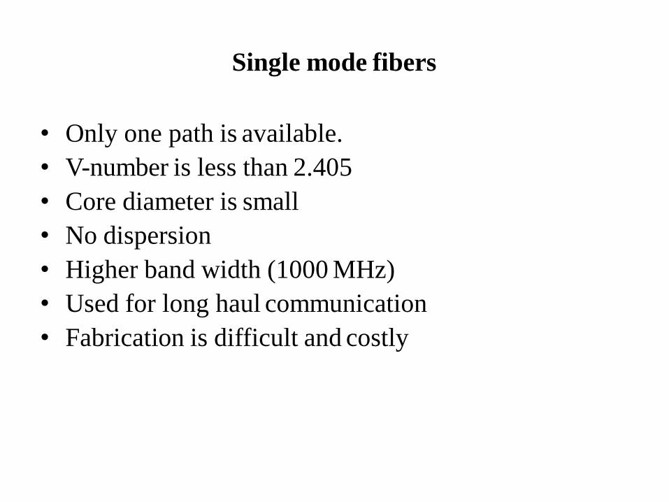
• Only one path is available.
• V-number is less than 2.405
• Core diameter is small
• No dispersion
• Higher band width (1000 MHz)
• Used for long haul communication
• Fabrication is difficult and costly

Multimode fibers

Multi mode fibers
• If more than one mode is transmitted through opticalfiber, then it is said to be a multimodefiber.
• The larger core radii of multimode fibers make iteasier to launch optical power into the fiber andfacilitate the end to end connection of similarpowers.
Some of the basic properties of multimode optical fibers are listed below :
• More than one path is available
• V-number is greater than 2.405

Types of fibers based on Refractive Index Profile
Based on the refractive index profile of the core and
cladding, the optical fibers are classified intotwo
types:
– Step index fiber
– Graded index fiber

Step index fiber
• In a step index fiber, the refractive index changes in astep fashion, from the centre of the fiber, the core, tothe outer shell, the cladding.
• It is high in the core and lower in the cladding. Thelight in the fiber propagates by bouncing back andforth from core-cladding interface.
• The step index fibers propagate both single andmultimode signals within the fiber core.
• The light rays propagating through it are in the formof meridinal rays which will cross the fiber core axisduring every reflection at the core – claddingboundary and are propagating in a zig – zagmanner.

Step index fiber
• With careful choice of material, dimensions and ,the total dispersion can be made extremely small, lessthan 0.1 ps /(km nm), making this fiber suitable foruse with high data rates.
• In a single-mode fiber, a part of the light propagatesin the cladding.
• The cladding is thick and has low loss.
• Typically, for a core diameter of 10 m, the claddingdiameter is about 120 m.
• Handling and manufacturing of single mode stepindex fiber is more difficult.

Step index multimode fibers
•A multimode step index fiber is shown.
• In such fibers light propagates in manymodes.
•The total number of modes MN increases
with increase in the numerical aperture.
•For a larger number of modes, MN
approximated by
can be

Step index multimode fibers
where d = diameter of the core of the fiber and V = V –number or normalized frequency.The normalized frequency V is a relation among the fibersize, the refractive indices and the wavelength. V is thenormalized frequency or simply the V number and is givenby
where a is the fiber core radius, is the operatingwavelength, n1 the core refractive index and the relativerefractive index difference

Graded index fiber
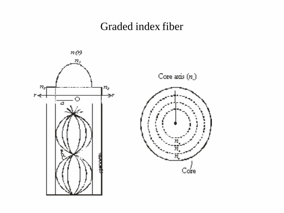
• A graded index fiber is shown in Fig.3.27. Here, therefractive index n in the core varies as we move awayfrom the centre.
• The refractive index of the core is made to vary in theform of parabolic manner such that the maximumrefractive index is present at the centre of thecore.
• The refractive index (n) profile with reference to theradial distance (r) from the fiber axis is givenas:

Graded index fiber
12
1 2Δ
n 1
a
r 2
1
n1(1 2Δ) 2
when r = 0, n(r) = n1r < a, n(r) =
r ≥ a, n(r) = n2 =
At the fiber centre we have n1; at the cladding wehave n2; and in between we have n(r), where n isthe function of the particular radius as shown inFig. simulates the change in n in a stepwisemanner.
Graded index fiber

Graded index fiber
• Each dashed circle represents a different refractive
index, decreasing as we move away from the fiber
center.
• A ray incident on these boundaries between na – nb,
nb – nc etc., is refracted.
• Eventually at n2 the ray is turned around and totally
reflected.
• This continuous refraction yields the ray tracings as
shown in Fig.

Graded index fiber
• The light rays will be propagated in the form skew rays (or) helical rays which will not cross the fiber axis at any time and are propagating around the fiber axis in a helical or spiral manner.
• The effective acceptance angle of the graded-index fiber is somewhat less than that of an equivalentstep-index fiber. This makes coupling fiber to the light source more difficult.

Reference book
Introduction to fiber optics, AK Ghatak & K Thyagarajan, Cambridge UniversityPress (1998)