introduction - mechanical and construction...
TRANSCRIPT

Abstract—This paper presents the first ever experimental demonstration of a multiple-input multiple-output (MIMO) visible light communications system employing four silicon (Si) light emitting diodes (LEDs) and four organic photodetectors (OPDs) as transmitters and receivers, respectively. The proposed link is relatively low cost and it employs the on-off keying (OOK) modulation format offering a data rate of 200 kb/s without the need for equalization, which is a significant increase compared with previous non-equalized systems. In order to speed up date rates further, we implement an artificial neural network (ANN) to classify the signal and correct the error induced by the matrix inversion at the receiver, allowing a gross bit rate of 1.8 Mb/s in the best case.
Index Terms— Artificial neural network, multiple-input multiple-output, organic photodetector, visible light communications
I. INTRODUCTION
ULTIPLE-input multiple-output (MIMO) systems based on the concept of channel matrix inversion [1] are an excellent way to increase the aggregate
bit rates in visible light communications (VLC) systems. As a result they have garnered a significant amount of interest in the research community with many different methods of implementing the MIMO technique being proposed [1-6]. For example, different modulation schemes are reported in [2] and [5] while [4] offers a spatially diverse scheme where only one transmitter is active at any given time. Furthermore, based on the simulation results in [3] there is a strong claim that a complex imaging receiver is required in order to receive an error free link [1, 3, 7] due to an ill-conditioned channel matrix rank.
M
In this paper we experimentally verify that it is possible to recover a 4 × 4 MIMO link without employing a complex imaging receiver at every point on the receiving plane while also setting a world record bit rate of 1.8 Mb/s for a non return-to-zero OOK VLC link that uses Si LEDs and OPDs.
While the benefits of solid state lighting in VLC are well known (high output power, bandwidths of several MHz [8]), using OPDs as the receiver for VLC systems is a subject in its’ infancy. So far only a single-input single-output (SISO) link has been reported [9] where an artificial neural network (ANN) equalizer is being employed to increase the data rate to 750 kb/s considering that the OPD bandwidth is only 30 kHz. In this work we present for the first time a MIMO system based on four individual commercial Si LEDs and four OPDs that are mounted on the same substrate.
The OPD used is based on the bulk heterojunction (BHJ) concept [10], which is an interpenetrated blend of electron donor and electron acceptor, as opposed to the common p–n junction that Si PDs utilizes. It was manufactured by Siemens
AG Corporate Technology by the spray deposition technique as reported in [11]. When comparing organic technologies with their crystalline Si counterparts, the real advantage is the price. The total cost of materials for the poly(3-hexylthiophene):[6,6]-phenyl C61-butyric acid methylester (P3HT:PCBM) system implemented here is ~ € 0.20/cm2, which is very inexpensive. The materials can be processed into a solution that can be sprayed onto the substrate, allowing very low cost and straightforward manufacturing. Besides spray coating there are other ways to produce devices, see [12] for further details on a number of methods. Additionally, the OPD BW is dynamic [13], and its performance is controlled by the incident light intensity. Under a high light intensity (> 300 μW/cm2) the number of charge carriers generated is greater than the number of traps at the interface meaning that the time constant of the plate capacitance controls the cut-off frequency as in Si PDs. Conversely at low light intensities the number of traps is greater than the number of charge carriers, meaning that the BW is controlled by the time constant of the interface traps.
A further advantage of the OPD under test is that is has four independent diodes spaced 1.2 cm apart each with 1 cm2
photoactive area meaning that 4 × 4 (4-transmitters and 4-receivers) MIMO is a natural progression on SISO links. No additional electronics or photodetectors are required at the receiver as in Si based MIMO, and therefore there is no additional cost.
Since there are four diodes on the OPD substrate, 4 × 4 MIMO is investigated in this paper. While the theory of demodulating a MIMO link is extremely simple (outlined mathematically in Section II), a series of pilot tones are transmitted from the first transmitter to all receivers in order to find the channel response (while keeping the rest of the transmitters off) and repeating for each transmitter. A matrix of channel coefficients is produced, inverted and multiplied with the received data in order to find the transmitted data. In practice this is a significant challenge for band limited systems due to the intersymbol interference (ISI) induced distortion of the reference signals [9] that make up the channel matrix coefficients.
A MIMO-ANN System for Increasing Data Rates in Organic Visible Light Communications
Systems
Paul Anthony Haigh1, Zabih Ghassemlooy1, Ioannis Papakonstantinou2, Francesco Arca3,Sandro Francesco Tedde3, Oliver Hayden3 and Sujan Rajbhandari1
1 Optical Communications Research Group, Northumbria University, Newcastle-upon-Tyne, NE1 8ST2 Department of Electrical & Electronic Engineering, University College London, London, UK
3 Siemens AG Corporate Technology, Erlangen, [email protected]
MIMO systems are typically implemented in the radio frequency domain where a multipath environment is inherent. There are many reports of using an ANN to find the channel response [14, 15]; however to the best of our knowledge there are no reports of applying an ANN at all in VLC MIMO systems. This is because they are mostly used for correcting ISI at the receiver. One cause of ISI is transmitting data outside of the modulation BW, which is not a problem that is observed in MIMO systems explicitly, since the quality of the channel coefficient matrix has more impact in recovering the data than the ISI. In this paper we demonstrate that not only is it possible to implement the ANN to equalize the received signal but it is also possible to use the ANN to set a new record data rate based upon the ANN for a large coverage area beneath the transmitter array.
This paper is organized as follows. In Section II the MIMO theory and test setup is outlined while in Section III the ANN is described. Section IV shows the results and in Section V conclusions are drawn.
II. MULTIPLE-INPUT MULTIPLE-OUTPUT
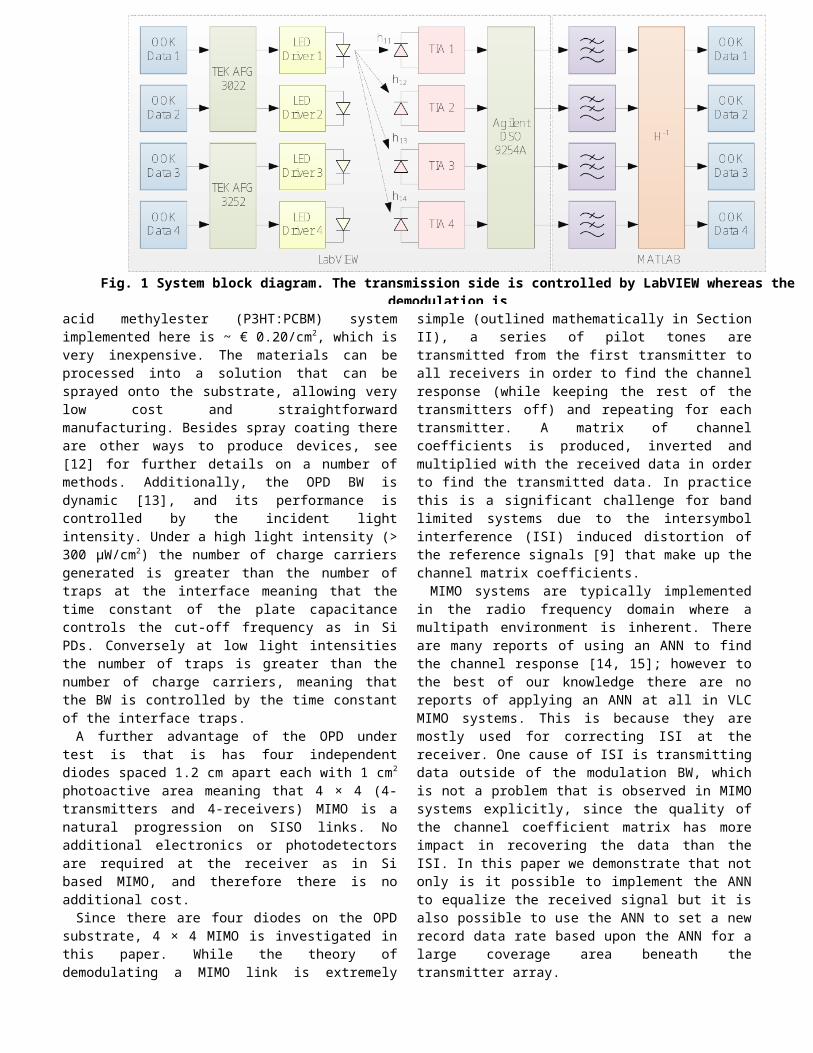
The concept of MIMO is outlined in Fig. 1. Over the next few subsections the transmitter, channel and receiver are outlined.
A. TransmittersA pseudorandom binary sequence is generated and shaped
into an OOK signal in MATLAB. Two arbitrary function generators (AFGs) with a peak-to-peak output voltage of 5 V are synchronized. Synchronization of the AFGs is not required as the data is recoverable regardless; however it does simplify the demodulation process. Autocorrelation will only be required once for all channels as the relative delay at the receiver will be the same. Each channel is buffered using a NAND gate with high output impedance then mixed with a bias current of 350 mA. The bias current is generated by a simple transistor circuit given in [16] to eschew the use of a coupling capacitor and therefore avoid the baseline wander phenomena that occurs in organic VLC links [9]. The transmitter array is made up of four yellow phosphor blue chip Philips Luxeon Rebel DS64 LEDs. The blue chip LED has a high order modulation BW; however the slow response of the yellowish phosphor limits the BW to several MHz. This BW is still approximately an order of magnitude higher than that of
the OPD, which means that the OPD is limiting the link BW. The LED is a Lambertian emitter as given by [17]:
R0 (θ )=[ m+12 ]cos (θ )m (1)
where m is the Lambertian number and θ is the angle of emission. The transmitter array is divided into four serial data streams, each transmitting a unique pseudorandom binary sequence.
B. Channel matrixAt the receiver the incident light from each transmitter adds
by superposition to form the MIMO symbol. The VLC channel gain from transmitter i to receiver j is given by [18]:
hij=Ar
d ij2 R0 (θij ) cos (φij ) (2)
where Ar is the photodetector area, dij is the distance between transmitter i and receiver j, θij is the emission angle and finally ϑij is the angle of incidence. Clearly, if there is no light incident to the receiver, hij = 0. From (2) it is noteworthy that there is no phase component, meaning that no phase distortion occurs in the channel and only a flat attenuation is experienced i.e. it is a DC gain < 1. There is a line of sight (LOS) path between each transmitter and receiver; considering there are four transmitters this gives a total of 16 LOS paths. It should be noted that there is a multipath component;, however studies show that the strongest multipath component is at least 7 dB lower than the LOS component [3], so the multipath effect is ignored in this experiment. Using 16 LOS paths a channel matrix H containing all the useful information about the channel can be built as [17]:
(3)Hence, the received electrical signal vector immediately
after the photodetector is given by [1]:Prx=H P tx+n (4)
where Ptx and Prx are transmit and receive vectors, respectively of size 4 × η, where η is the number of
Fig. 1 System block diagram. The transmission side is controlled by LabVIEW whereas the demodulation isperformed in MATLAB
44434241
34333231
24232221
14131211
hhhhhhhhhhhhhhhh
H
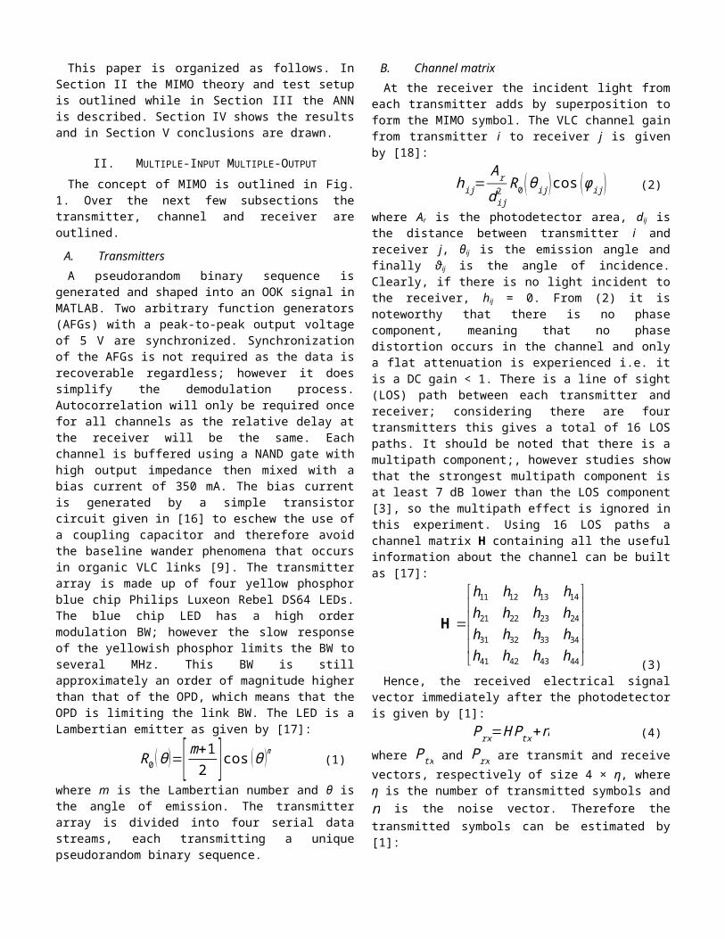
transmitted symbols and n is the noise vector. Therefore the transmitted symbols can be estimated by [1]:
ψ=H−1 Prx (5)where ψ is the estimate of Ptx. Notice that for the recovery of data, the channel matrix H must be full rank. It is clear that the quality of the estimated data is dependent on H. The quality of the H-matrix consequently depends on the quality of measurement of the individual channel coefficients. The channel coefficient hij is controlled by dij
2 as (θij and φij change as a function of modifying dij
2) while Ar is a constant. A further consideration is that ψ is dependent on the noise n. So far, no studies have been carried out on the impact of the noise on H, which is something we expect to do in future studies. Tracking dij
2 in real time to build the H-matrix would be very problematic experimentally as it would involve a feedback channel - something not implemented in this work.
A far more simplistic approach is a histogram method. One LED transmits data over the channel while the remaining receivers are not active. The DC level is removed from the signal and the electrical signal levels are found. Recalling Vpp
= 5 V, removing the DC corresponds to signal levels of 2.5 V. Therefore it is easy to rapidly find the DC gain of the given channel with a simple division. The method is then repeated for each LED in the transmitter to build H – see Fig. 2 for a two channel example.
Fig. 2 A two channel example of the histogram method exploited to find the channel response
There is a drawback to this method; when transmitting outside the BW of the OPD, the influence of ISI will be significant, degrading the peaks of the histogram meaning the estimate of the signal will not be optimal. In the presence of severe ISI the histogram will fail completely since the histogram will not find any distinction between the two levels. In this test, the histogram measurement is only performed once for the each channel because the receiver is not moving continuously. For a real time measurement, H would be periodically updated.
C. ReceiverThe x – z and x – y plane geometries are illustrated in Fig.
3(a) and Fig. 3(b), respectively where Fig. 3(a) demonstrates the previously outlined concepts and Fig. 3(b) shows the receiver plane geometry. The distances between the x – z plane and the x – y plane are both 10 cm. Only one quarter of the
possible area is tested, since the performance is expected to be symmetrical around the center. This area is separated into nine sections of 5 cm2 (S1:S9) to give an outline of the position-dependent performance. However before the performance is analyzed, it is necessary to characterize the OPD under test.
Fig. 3 (a) x – z plane (distance 10 cm) and (b) x – y plane (distance 10 cm): the receiver plane divided into sections
S1-S9 for BER measurementsAs mentioned, there are four diodes on the substrate, as
illustrated in Fig. 4, which also shows the spatial characteristics of the OPD and the responsivity of the OPD is shown in Fig. 5. The distance dij between the transmitter and receiver is set to maximize the light density while maintaining full coverage by all other LEDs. Within the receiving plane, the maximum light density is found directly beneath one of the LEDs [4], i.e. section S3, which corresponds to a light density of > 300 μW/cm2 and a BW of 177 kHz. The minimum is found in the center of the receiving plane; section S7 where the light density is ~ 300 μW/cm2 and the BW is 133 kHz, see Fig. 6.
The light density is measured with a thermopile of area 12 cm2 and the bandwidth is found by performing a fast Fourier transform on a short pulse (duration 1 μs with rise and fall times of 2 ns) transmitted over all 4-LEDs. The BW decreases from a maximum of 177 kHz to 133 kHz as the receiver approaches the center of the receiving plane. This difference is quite large in relation to the magnitude of the BW. However, in terms of a MIMO signal at the center of the receiving plane the contribution from each LED is much greater, so it is expected that this position will offer the largest data rate. Normally it would be predicted that the largest BW would offer the greatest data rate, yet since the bit rate will exceed the BW in all sections, ISI will distort the signals significantly thus causing the histogram method to fail.
LED
x
z
(a)
5 cm
5 cm
x
y
S1 S2
S4 S5
S7 S8
10 cm
10 cm
S6
S3
S9
(b)
OPD
10 cm

Fig. 4 Bottom view photograph of the OPD showing the spatial characteristics
Fig. 5 OPD Responsivity in comparison to a Si PD – in the visible region (~ 400 – 800 nm); the OPD has superior responsivity in the visible range and blocks infrared (meaning no additional infrared filtering is required) due to a band gap energy of ~ 2 eV.
The data is transferred in each section and sampled with an Agilent DSO9254A real time scope controlled by LabVIEW. In the histogram method, data demodulation and estimation are all performed in MATLAB. While a field programmable gate array (FPGA) could have been implemented for a real time result, there was a strong indication from the literature that the experiment would not prove conclusive without an imaging lens [1, 3, 7]. Therefore to avoid the costly development time MATLAB is selected for this first demonstration and we will proceed to FPGA development in future work.
Fig. 6 BW in the highest and lowest light densities on the receiving plane
III. ARTIFICIAL NEURAL NETWORK EQUALIZER
Literature clearly demonstrates that the ANN is the most effective method for equalizing ISI induced by a communications channel [19-23]. The most popular ANN for channel equalization is the single layer multilayer perceptron (MLP). This is because it outperforms all other linear transversal equalizers and can map any input-out sequence including non-linear functions [19]. The ANN used in this test has N input taps, N neurons and one output node γ. Each input tap xi, where i = 1, …, N, has an associated weight wi. The weight values are found by training with the Levenberg-Marquardt back propagation (BP) algorithm that aims to reduce the error function E(n) between a header sequence δ(n), known at the receiver and the estimated data ψ(n) from the MIMO demodulation [9]:
E (n )=‖ψ (n )−δ (n)‖2 (6)The aforementioned weights between input i and neuron j are adjusted as a function of E(n) such that [19]:
w ij (n+1 )=wij (n )−η ∂ E (n )∂ wij (n )
(7)
where η is the learning rate parameter, which if set too large causes an unstable system and if set too low means slow convergence. Therefore we use the adaptive converging rate parameters to optimize convergence rates [24]. The output y is given by [19]:
γ= f (b+∑i
wi x i) (8)
where i = 0, …, N if a bias b exists and i = 1, …, N otherwise.While the ANN is normally used to correct the ISI induced
by a band limited system, in this case we use it to correct the errors induced by an ill conditioned matrix inversion; i.e. the ANN will not have any direct influence on the H-matrix, it will aim to minimize the error function between the transmitted and received data – the ANN is not performing channel deconvolution.
IV. RESULTS
The Q-factors of the four channels in every position were measured. The best results are found when the receiver is in

section S7 as predicted with the results as well as the eye diagram shown in Fig. 7. A Q-factor of 4.7 is equivalent to a bit error rate (BER) of 10-6, which is commonly accepted as error free in VLC [9, 25]. Fig. 7 also depicts that a 200 kb/s link can be established without an equalizer as two 100 kb/s channels could be demodulated error free (Ch3 and Ch4). One possible reason for this is due to the fact that the measurement was made horizontally over the optical bench where the transmitters and receivers are perpendicular to the bench, as opposed to the case where transmitters and receivers are parallel to the bench; thus resulting in large multipath components for the two channels closest to the bench, i.e. Ch1 and Ch2 in this case. As mentioned, the rank of H is crucial for recovering data; any loss of rank in the channel matrix means that the data can’t be recovered. Since only two channels could be demodulated error free, H is an ill-conditioned matrix and as a result a portion of the data is lost as indicated by the condition number κ(H) = 70.
It should be noted that a 200 kb/s link with no equalizer is significantly larger than the highest previously reported case of 30 kb/s in [9] by around seven times. However a more effective method of increasing data rates without an equalizer might be to scale down the number of transmitters to two.
When considering the ANN equalizer, the achievable data rate for each section with all channels error free is illustrated in Fig. 8, where BER for all channels in sections S1, S3, S7 and S9 are averaged to produce a solitary curve rather than four curves per section. No other curves are illustrated since their performance lies between these sections. Sections S2 and S6 can offer 1.5 Mb/s while sections S5, S5 and S8 can offer 1.7 Mb/s. As predicted section S7 offers the highest data rate of 1.8 Mb/s while section S3 with the highest BW offers 1.4 Mb/s. This corresponds to four parallel channels transmitting 450 kb/s and 350 kb/s for each section, respectively. This represents an extremely large increase of over 1 Mb/s on the previously reported maximum data rate of 750 kb/s, not to mention exceeding the modulation BW by an order of magnitude. The performance difference of 300 kb/s observed between S1 – S9 is not a function of the BW as previously outlined, since the BW is maximized when the achievable data rate is minimized. Therefore considering section S3, the contribution to the MIMO symbol from the furthest LED is minimized in comparison to section S7 where the relative contributions from each LED are approximately equal meaning there it is more likely that the symbol will be recovered. This is reflected by the other sections, whereas the deviation from the center point increases, the data rate decreases.
Fig. 7 Received Q-factor for section S7 with eye diagram inset at 50 kb/s The dashed line represents Q = 4.7,
corresponding to a BER of 10-6It was suggested in [3] that section S7 would be impossible
to recover due to the matrix correlation, however the data could recovered in these tests. While in theory, if the channel paths and transmission power are identical, the matrix will correlate [3]. In practice, however this situation is extremely unlikely to occur due to the combination of the additive white Gaussian noise (AGWN) that exists in the system plus the fact that the LEDs are not perfectly identical so will have slightly different output characteristics.
Fig. 8 Aggregate BER and bit rate for the four key sections tested
In the worst case scenario, 1.4 Mb/s could be achieved, which still denotes a sizeable improvement as mentioned. This result is important not only for this reason, but because it means that data can be demodulated at all positions on the receiving plane indicating that MIMO is a valid technique for future organic VLC systems. It is important not to forget that in all cases an ANN was required to equalize the errors induced throughout the system. Without the ANN, only 100 kb/s could be transmitted over two channels. While not close to the 1.8 Mb/s reported above, in comparison to other unequalized LED to OPD links, this is still an increase over previously published work [9].

V. CONCLUSION
In this paper we have presented an experimental demonstration of a MIMO system for an organic VLC system. Whilst providing this demonstration, the record data rate of 750 kb/s for VLC systems with Si LEDs and OPDs as transmitter and receiver, respectively has been well broken, as 1.8 Mb/s can now be transmitted, which is a significant step in the progression of organic VLC. The major challenge in this paper was to overcome the poorly conditioned matrix to recover the data at the receiver. In order to achieve this, we proposed an ANN equalizer to map the input-output sequence and correct the errors, which resulted in achieving extremely high data rates. We also demonstrated the feasibility of VLC-MIMO without the use of an imaging receiver and for the first time, multi-Mb/s an organic VLC link.
Future work on this topic considers what is missing from this preliminary experiment. Firstly, an FPGA development is required to provide a real time link where we can fully explore the influence of white noise on H, which will allow the derivation of new theory on the recovery of MIMO symbols for VLC links. Secondly, in order to provide a full scale demonstration, the number of OLEDs needs to be scaled up to provide full illumination of a small room. It would be expected that the link has the same performance as in the small scale link that is presented here, and so far a full scale demonstration has not been demonstrated.
REFERENCES
[1] K. D. Dambul, D. C. O'Brien, and G. Faulkner, "Indoor Optical Wireless MIMO System With an Imaging Receiver," Photonics Technology Letters, IEEE, vol. 23, pp. 97-99, 2011.
[2] A. H. Azhar, T.-A. Tran, and D. O'Brien, "Demonstration of high-speed data transmission using MIMO-OFDM visible light communications," GLOBECOM Workshops (GC Wkshps), 2010 IEEE, pp. 1052 -1056, dec. 2010.
[3] Z. Lubin, D. O'Brien, M. Hoa, G. Faulkner, L. Kyungwoo, J. Daekwang, O. YunJe, and W. Eun Tae, "High data rate multiple input multiple output (MIMO) optical wireless communications using white led lighting," IEEE Journal on Selected Areas in Communications, vol. 27, pp. 1654-1662, 2009.
[4] R. Mesleh, R. Mehmood, H. Elgala, and H. Haas, "Indoor MIMO Optical Wireless Communication Using Spatial Modulation," in Communications (ICC), 2010 IEEE International Conference on, 2010, pp. 1-5.
[5] T. Fath, M. Di Renzo, and H. Haas, "On the performance of Space Shift Keying for optical wireless communications," in GLOBECOM Workshops (GC Wkshps), 2010 IEEE, pp. 990-994.
[6] Y. A. Alqudah and M. Kavehrad, "MIMO characterization of indoor wireless optical link using a diffuse-transmisson configuration," IEEE Transaction on communications, vol. 51, pp. 1554-1560, Sept. 2003.
[7] A. H. Azhar, T. Tuan-Anh, and D. O'Brien, "Demonstration of high-speed data transmission using MIMO-OFDM visible light communications," in GLOBECOM Workshops (GC Wkshps), 2010 IEEE, 2011, pp. 1052-1056.
[8] T. Komine and M. Nakagawa, "Fundamental analysis for visible-light communication system using LED lights," Consumer Electronics, IEEE Transactions on, vol. 50, pp. 100-107, 2004.
[9] P. A. Haigh, Z. Ghassemlooy, H. Le Minh, S. Rajbhandari, F. Arca, S. Tedde, O. Hayden, and I. Papakonstantinou, "Exploiting Equalization Techniques for Improving Data Rates in Organic Optoelectronic Devices for Visible Light Communications," Lightwave Technology, Journal of, vol. PP, pp. 1-1, 2012.
[10] C. J. Brabec, N. S. Sariciftci, and J. C. Hummelen, "Plastic Solar Cells," Adv. Funct. Mater., vol. 11, 2001.
[11] S. F. Tedde, J. Kern, T. Sterzl, J. Fürst, P. Lugli, and O. Hayden, "Fully Spray Coated Organic Photodiodes," Nano Lett., vol. 9, p. 980, 2009.
[12] H. Klauk, Organic Electronics: Materials, Manufacturing, and Applications: Wiley, 2006.
[13] F. Arca, S. Tedde, B. Popescu, D. Popescu, S. Locci, M. Sramek, P. Lugli, and O. Hayden, "Interface Trap States in Organic Photodiodes," vol. [submitted], 2012.
[14] K. K. Sarma and A. Mitra, "ANN based Rayleigh multipath fading channel estimation of a MIMO-OFDM system," in Internet, 2009. AH-ICI 2009. First Asian Himalayas International Conference on, 2009, pp. 1-5.
[15] L. Zhang and X. Zhang, "MIMO channel estimation and equalization using three-layer neural networks with feedback," Tsinghua Science and Technology, vol. 12, pp. 658-662, 2007.
[16] A. R. Hayes, "Digital Pulse Interval Modulation for Indoor Optical Wireless Communication Systems," PhD, Sheffield Hallam University, UK, 2002.
[17] J. R. Barry, J. M. Kahn, W. J. Krause, E. A. Lee, and D. G. Messerschmitt, "Simulation of multipath impulse response for indoor wireless optical channels," Selected Areas in Communications, IEEE Journal on, vol. 11, pp. 367-379, 1993.
[18] J. M. Kahn and J. R. Barry, "Wireless infrared communications," Proceedings of the IEEE, vol. 85, pp. 265-298, 1997.
[19] K. Burse, R. N. Yadav, and S. C. Shrivastava, "Channel Equalization Using Neural Networks: A Review," Systems, Man, and Cybernetics, Part C: Applications and Reviews, IEEE Transactions on, vol. 40, pp. 352-357, 2010.
[20] C. Jongsoo, M. Bouchard, and T. H. Yeap, "Decision feedback recurrent neural equalization with fast convergence rate," Neural Networks, IEEE Transactions on, vol. 16, pp. 699-708, 2005.
[21] F. Jiuchao, C. K. Tse, and F. C. M. Lau, "A neural-network-based channel-equalization strategy for chaos-based communication systems," Circuits and Systems I: Fundamental Theory and Applications, IEEE Transactions on, vol. 50, pp. 954-957, 2003.
[22] C. Jongsoo, A. C. C. Lima, and S. Haykin, "Kalman filter-trained recurrent neural equalizers for time-varying channels," Communications, IEEE Transactions on, vol. 53, pp. 472-480, 2005.
[23] X. Nan and L. Henry, "Blind equalization using a predictive radial basis function neural network," Neural Networks, IEEE Transactions on, vol. 16, pp. 709-720, 2005.
[24] L. Behera, S. Kumar, and A. Patnaik, "On adaptive learning rate that guarantees convergence in feedforward networks," IEEE Transactions on Neural Networks, vol. 17, pp. 1116-1125, 2006.
[25] J. Vucic, C. Kottke, S. Nerreter, K. Langer, and J. W. Walewski, "513 Mbit/s Visible Light Communications Link Based on DMT-Modulation of a White LED," Lightwave Technology, Journal of, vol. 28, pp. 3512-3518, 2011.