introduction - qps master catalogue.pdf · structural and component parts are manufactured from...
TRANSCRIPT
In 1991 Quality Pipe Supports (QPS) Ltd first supplied pipe supports into the powergeneration industry, and since then QPS has grown internationally as a major supplier of pipesupport systems to a wide range of industries.
Specialising in the design and manufacture of Pipe Support Systems and Fabricated SteelSupport Systems, QPS has the capability to fulfil all disciplines necessary for mechanical pipework installation. The truly distinct and refreshing approach adopted by QPS has alreadybeen embraced by many clients throughout industries such as construction, nuclear,refineries, offshore oil and gas, petro-chemical, pharmaceutical, power generation andutilities.
From its 56,000 sq ft premises based in Mid Wales, QPS displays a proven ability to offer itsclients total control through project work. From engineering design to manufacture andfabrication right through to final inspection, packaging and dispatch, clients operate safe in theknowledge that their requirements will be met with a proficient accuracy every time.
All operational aspects of the business are bound by the quality management systemaccredited to BS EN ISO 9001:2000, ensuring that the strict and stringent qualityrequirements expected by our clients are met time after time.
Our team of qualified and highly experienced engineers can give full support in design andalso practical advice to our clients. They also have the necessary know-how and expertise toconduct extensive site surveys and inspections providing ‘on the job’ information. Detailedreports and recommendations form part of the overall inspection process. This provides ourclients with original solutions that are easily implemented.
Structural and component parts are manufactured from high quality carbon,alloy and stainlesssteels.
QPS employs only qualified welders and all welding and fabrication is undertaken againstquality approved procedures.
Products are coated in accordance with customer specifications or requirements, andmanufactured to strict procedures to ensure effective protection against the elements.
QPS can supply a painting quality plan where specific paint finish is required. Standardfinishes include:-
Bright Zinc Electro Plating.Hot Dip Galvanising.Shot Blasting.Plastic Coating.
With the QPS ‘Support Selector Program’ our clients are now able to create their ownsupports. The step by step, easy to use approach, offers a quick and efficient way of pipesupport design. Once drawn, the design can be either printed or simply sent electronically toQPS for validation and supply.
Our sales engineers are always able to help with specific requirements and practical advice.For further copies of our catalogue or Support Selector Program please contact us on:-
Tel: +44 (0)1686 629 898 Fax: +44 (0)1686 629 797 E-mail: [email protected]: www.qps.co.uk
N.B. QUALITY PIPE SUPPORTS RESERVE THE RIGHT TO ALTER SPECIFICATIONS WITHOUT NOTICE.
I
INTRODUCTION
INTRODUCTION
II
Quality Pipe Supports (Q.P.S) Ltd, offer a wide range of services,from professional technical advice, to complete pipe supportdesign. Our highly experienced design engineers can offer comprehensive pipe support “Site Surveys”, which include a complete analysis of new and as-built piping systems. Togetherwith our “Review Reality” software, support designs come to life,giving an in-depth representation to project reviews.
Quality Pipe Supports (Q.P.S) Ltd, also offer complete generation of individual supports, and individual support drawings.AUTOCAD 2004 allows for individual customer specification, providing the opportunity for complete customization of pipe supports.
Services
Comprehensive pipe support surveys
Stress analysis for piping systems
Pipe support design for piping systems
Software generated individual support drawings(AutoCAD 2004)
In depth representation of pipe support designs(Review Reality Viewer)
QPS Selector Software
Please contact us for further details.
Through our highly constant quality of products, Q.P.S can ensurecomplete customer satisfaction. With thanks to our highly efficientservice and skilled team of sales engineers, Q.P.S will continue toprovide pipe supports which are second to none.
QUALITY PIPE SUPPORTS (Q.P.S) LTD
QUALITY COMES FIRST...
DESIGN CAPABILITIES
8 Interactive plant model visualisation8 Shows lifelike realism to project reviews8 Model file import capabilities8 Extreme texturing & Anti-Aliasing8 Software generated shadows8 Generates complex animations
8 Eliminates drawings& plastic models
8 Cost & projecttime savings
8 Improved project communication
Features...Features...
Benefits...Benefits...
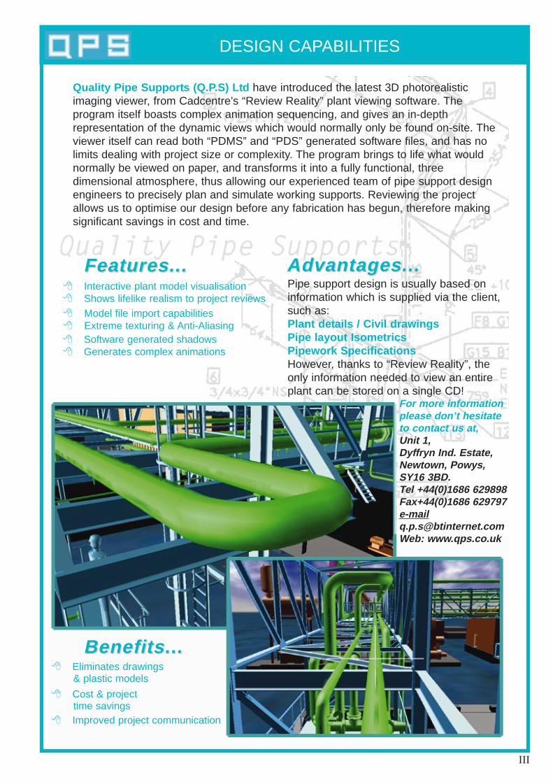
Quality Pipe Supports (Q.P.S) Ltd have introduced the latest 3D photorealistic imaging viewer, from Cadcentre’s “Review Reality” plant viewing software. The program itself boasts complex animation sequencing, and gives an in-depth representation of the dynamic views which would normally only be found on-site. Theviewer itself can read both “PDMS” and “PDS” generated software files, and has nolimits dealing with project size or complexity. The program brings to life what wouldnormally be viewed on paper, and transforms it into a fully functional, three dimensional atmosphere, thus allowing our experienced team of pipe support designengineers to precisely plan and simulate working supports. Reviewing the projectallows us to optimise our design before any fabrication has begun, therefore makingsignificant savings in cost and time.
Pipe support design is usually based oninformation which is supplied via the client,such as:Plant details / Civil drawingsPipe layout IsometricsPipework SpecificationsHowever, thanks to “Review Reality”, theonly information needed to view an entireplant can be stored on a single CD!
Advantages...Advantages...
For more informationplease don’t hesitateto contact us at,Unit 1, Dyffryn Ind. Estate,Newtown, Powys,SY16 3BD.Tel +44(0)1686 629898Fax+44(0)1686 [email protected]: www.qps.co.uk
III

CONTENTS
SSSSeeeecccc tttt iiii oooo nnnn 1111 CCCCoooo nnnn ssss tttt aaaannnn tttt SSSSpppp rrrr iiii nnnn gggg HHHHaaaannnn gggg eeeerrrr ssss ....
SSSSeeeecccc tttt iiii oooo nnnn 2222 VVVVaaaarrrr iiii aaaabbbb llll eeee SSSSpppp rrrr iiii nnnn gggg HHHHaaaannnn gggg eeeerrrr ssss ....
SSSSeeeecccc tttt iiii oooo nnnn 3333 AAAA nnnn cccc iiii llll llll aaaarrrr yyyy EEEEqqqq uuuu iiii pppp mmmm eeeennnn tttt ....
SSSSeeeecccc tttt iiii oooo nnnn 4444 BBBB SSSS3333999977774444 EEEEqqqq uuuu iiii pppp mmmm eeeennnn tttt ....
SSSSeeeecccc tttt iiii oooo nnnn 5555 DDDDyyyy nnnn aaaammmm iiii cccc EEEEqqqq uuuu iiii pppp mmmm eeeennnn tttt ....
SSSSeeeecccc tttt iiii oooo nnnn 6666 IIIIssss oooo llll aaaatttt iiii oooo nnnn EEEEqqqq uuuu iiii pppp mmmm eeeennnn tttt ....
SSSSeeeecccc tttt iiii oooo nnnn 7777 IIIInnnn ssss uuuu llll aaaatttt iiii oooo nnnn EEEEqqqq uuuu iiii pppp mmmm eeeennnn tttt ....
SSSSeeeecccc tttt iiii oooo nnnn 8888 FFFFaaaabbbb rrrr iiii cccc aaaatttt eeeedddd SSSStttt eeeeeeee llll wwww oooo rrrr kkkk ....
SSSSeeeecccc tttt iiii oooo nnnn 9999 SSSStttt aaaa iiii rrrr cccc aaaassss eeeessss ,,,, WWWWaaaallll kkkk wwww aaaayyyy ssss &&&& BBBB aaaallll uuuu ssss tttt rrrr aaaadddd iiii nnnn gggg ....
SSSSeeeecccc tttt iiii oooo nnnn 11110000 UUUUnnnn iiii ssss tttt rrrr uuuu tttt ....
SSSSeeeecccc tttt iiii oooo nnnn 11111111 LLLL iiii nnnn dddd aaaapppp tttt eeeerrrr ssss ....
IV
MAIN INDEX
MAIN INDEX
V
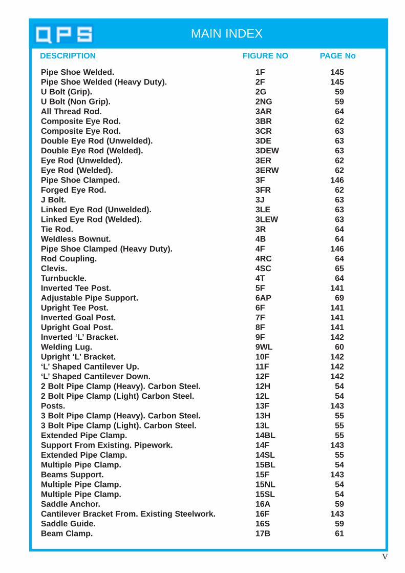
DESCRIPTION FIGURE NO PAGE No
Pipe Shoe Welded.Pipe Shoe Welded (Heavy Duty).U Bolt (Grip).U Bolt (Non Grip).All Thread Rod.Composite Eye Rod.Composite Eye Rod.Double Eye Rod (Unwelded).Double Eye Rod (Welded).Eye Rod (Unwelded).Eye Rod (Welded).Pipe Shoe Clamped.Forged Eye Rod.J Bolt.Linked Eye Rod (Unwelded).Linked Eye Rod (Welded).Tie Rod.Weldless Bownut.Pipe Shoe Clamped (Heavy Duty).Rod Coupling.Clevis.Turnbuckle.Inverted Tee Post.Adjustable Pipe Support.Upright Tee Post.Inverted Goal Post.Upright Goal Post.Inverted ‘L’ Bracket.Welding Lug.Upright ‘L’ Bracket.‘L’ Shaped Cantilever Up.‘L’ Shaped Cantilever Down.2 Bolt Pipe Clamp (Heavy). Carbon Steel.2 Bolt Pipe Clamp (Light) Carbon Steel.Posts.3 Bolt Pipe Clamp (Heavy). Carbon Steel.3 Bolt Pipe Clamp (Light). Carbon Steel.Extended Pipe Clamp.Support From Existing. Pipework.Extended Pipe Clamp.Multiple Pipe Clamp.Beams Support.Multiple Pipe Clamp.Multiple Pipe Clamp.Saddle Anchor.Cantilever Bracket From. Existing Steelwork.Saddle Guide.Beam Clamp.
1F2F2G2NG3AR3BR3CR3DE3DEW3ER3ERW3F3FR3J3LE3LEW3R4B4F4RC4SC4T5F6AP6F7F8F9F9WL10F11F12F12H12L13F13H13L14BL14F14SL15BL15F15NL15SL16A16F16S17B
145145
595964626363636262
146626363636464
146646564
14169
141141141142
60142142142
5454
143555555
1435554
143545459
1435961

MAIN INDEX
VI
DESCRIPTION FIGURE NO PAGE No
Sliding Support Guide.Beam Clamp.Pipe Chair .Beam Clamp.Pipe Base Support.Wall Bracket.3 Bolt Pipe Clamp (Heavy) Alloy S teel.3 Bolt Pipe Clamp (Light) Alloy S teel.2 Bolt Pipe Clamp (Heavy).2 Bolt Pipe Clamp (Light).3 Bolt Pipe Clamp (Heavy -20°C to 400°C).3 Bolt Pipe Clamp (Light -20°C to 400°C).3 Bolt Pipe Clamp (Heavy).3 Bolt Pipe Clamp (Light).3 Bolt Pipe Clamp.4 Bolt Riser Clamp.6 Bolt Riser Clamp.10 Bolt Riser Clamp (Boiler Plate).10 Bolt Riser Clamp (Alloy S teel -20°C to 510°C).10 Bolt Riser Clamp (Alloy S teel 510°C to 540°C).10 Bolt Riser Clamp (Alloy S teel 540°C to 570°C).‘U’ Bolt (Non Grip) S teel Pipes.‘U’ Bolt (Non Grip) Cast Iron Pipes.‘U’ Bolt (Grip) S teel Pipes.‘U’ Bolt (Non Grip) Cast Iron Pipes.Over Straps.Beam Welding Att achment s.Over StrapsOver StrapsOver StrapsDee Shackle1 Piece Pipe S trap.‘U’ Strap. Spring Cage.Spring Cage.Sling Rod Cage.Sling Rod Cage.Hookbolt (T o Grip)Hookstrap.Overstrap.Hardwood BlockHardwood BlockUniversal Beam Clip.Insulated 2 Bolt Pipe Clamp.Insulated 3 Bolt Pipe Clamp. Insulated Pipe Saddle.Clip S trip
17F18B18F19B19F20F20H20L51H51L57H57L58H58L596162636465666768697071727374757992939596979899100 HS100OS101A101B101107108109110CS
14461
14461
144144
555585858686
86-8786-8786-87
888992
90-9190-9190-91
84848484949496969699999397979898959595
119119100122122121121
MAIN INDEX
VII
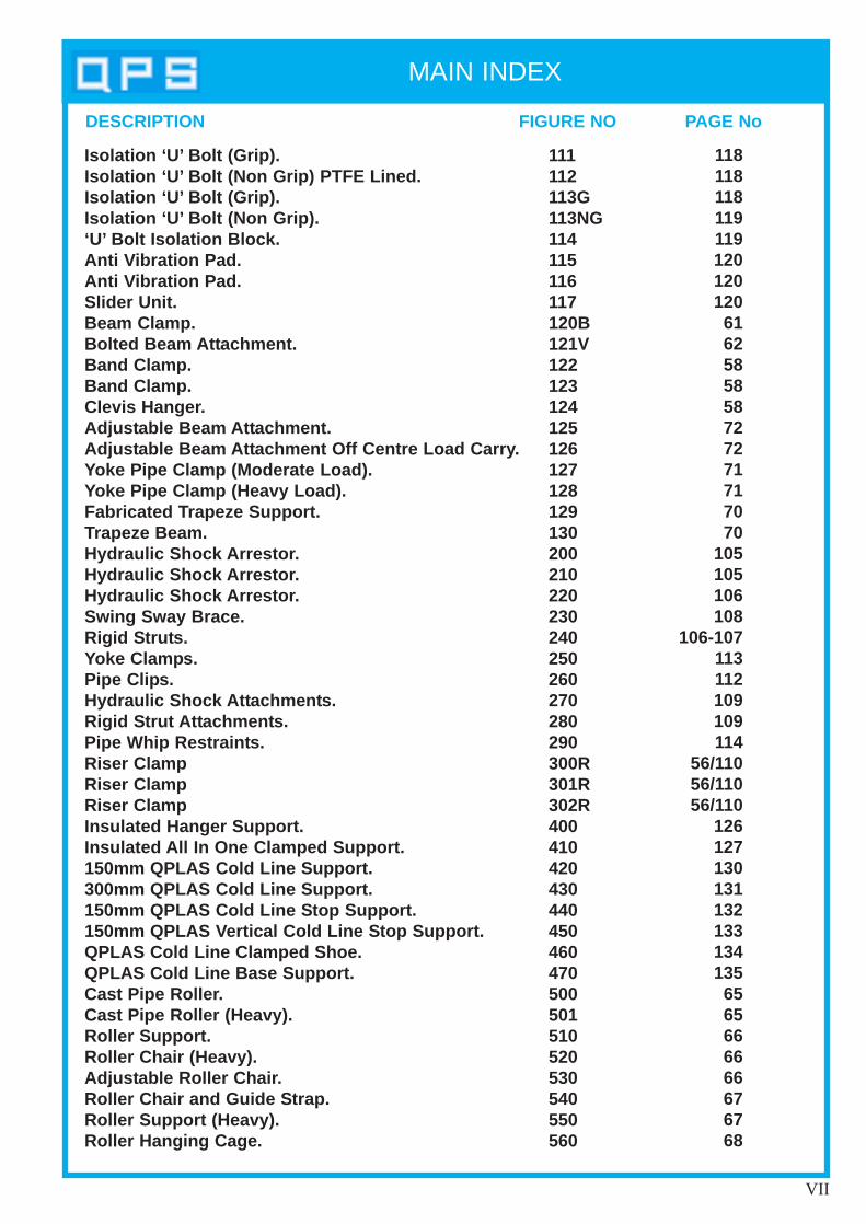
DESCRIPTION FIGURE NO PAGE No
Isolation ‘U’ Bolt (Grip).Isolation ‘U’ Bolt (Non Grip) PTFE Lined.Isolation ‘U’ Bolt (Grip).Isolation ‘U’ Bolt (Non Grip).‘U’ Bolt Isolation Block.Anti V ibration Pad.Anti V ibration Pad.Slider Unit.Beam Clamp.Bolted Beam Att achment.Band Clamp.Band Clamp.Clevis Hanger .Adjust able Beam Att achment.Adjust able Beam Att achment Off Centre Load Carry .Yoke Pipe Clamp (Moderate Load).Yoke Pipe Clamp (Heavy Load).Fabricated T rapeze Support.Trapeze Beam.Hydraulic Shock Arrestor .Hydraulic Shock Arrestor .Hydraulic Shock Arrestor .Swing Sway Brace.Rigid S trut s.Yoke Clamp s.Pipe Clip s.Hydraulic Shock Att achment s.Rigid S trut Att achment s.Pipe Whip Restraint s.Riser ClampRiser ClampRiser ClampInsulated Hanger Support.Insulated All In One Clamped Support.150mm QPLAS Cold Line Support.300mm QPLAS Cold Line Support.150mm QPLAS Cold Line S top Support.150mm QPLAS V ertical Cold Line S top Support.QPLAS Cold Line Clamped Shoe.QPLAS Cold Line Base Support.Cast Pipe Roller .Cast Pipe Roller (Heavy). Roller Support.Roller Chair (Heavy).Adjust able Roller Chair .Roller Chair and Guide S trap.Roller Support (Heavy).Roller Hanging Cage.
111112113G113NG114115116117120B121V122123124125126127128129130200210220230240250260270280290300R301R302R400410420430440450460 470500501510520530540550560
118118118119119120120120
6162585858727271717070
105105106108
106-107113112109109114
56/11056/11056/110
126127130131132133134135
6565666666676768
MAIN INDEX
VIII
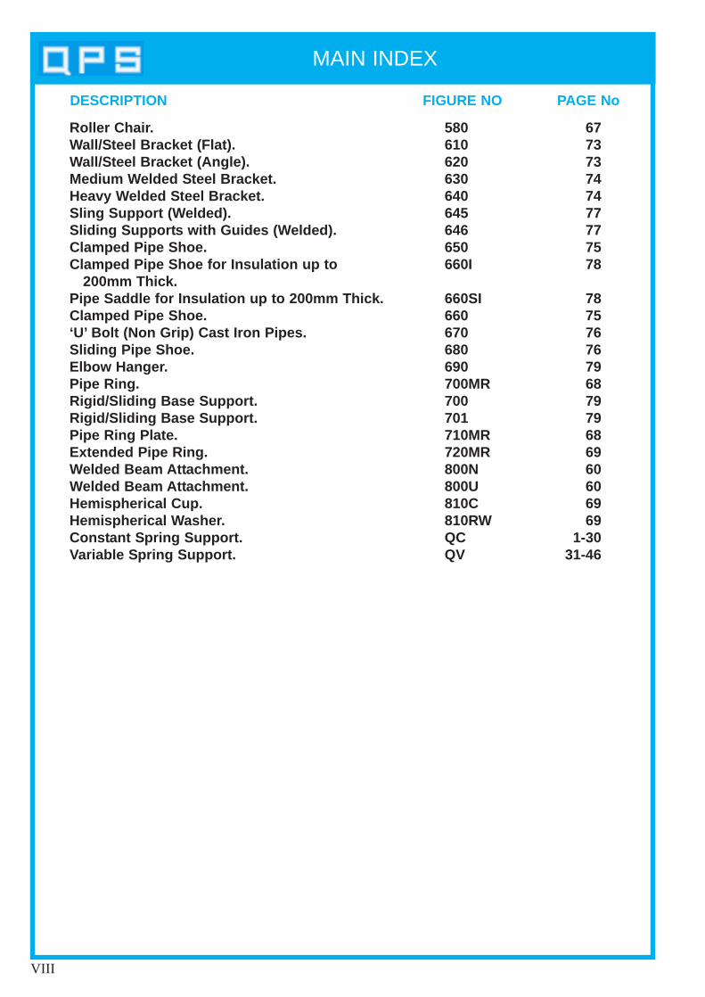
DESCRIPTION FIGURE NO PAGE No
Roller Chair .Wall/Steel Bracket (Flat).Wall/Steel Bracket (Angle).Medium W elded S teel Bracket.Heavy Welded S teel Bracket.Sling Support (W elded).Sliding Support s with Guides (W elded).Clamped Pipe Shoe.Clamped Pipe Shoe for Insulation up to
200mm Thick.Pipe Saddle for Insulation up to 200mm Thick.Clamped Pipe Shoe.‘U’ Bolt (Non Grip) Cast Iron Pipes.Sliding Pipe Shoe.Elbow Hanger .Pipe Ring.Rigid/Sliding Base Support.Rigid/Sliding Base Support.Pipe Ring Plate.Extended Pipe Ring.Welded Beam Att achment.Welded Beam Att achment.Hemispherical Cup.Hemispherical W asher .Const ant Spring Support.Variable S pring Support.
580610620630640645646650660I
660SI660670680690700MR700701710MR720MR800N800U810C810RWQCQV
677373747477777578
7875767679687979686960606969
1-3031-46
Constant SpringSupports
Section 1
DESCRIPTION
Page 1
Design PrincipleThe Quality Constant Support is designed to allow the supported pipework to expandvertically upwards or downwards, whilst maintaining a constant supporting effortthroughout the travel range.
This is achieved by transferring the load of the supported pipework to the coiledcompression spring via a cranked load arm. As the load arm moves through its travelrange the resulting moments of the pipework load and spring, are perfectlycounterbalanced about the main pivot shaft.
ConstructionThe Quality Constant Support units are robustly constructed, with various arrangementsfor attachment to pipework and supporting steelwork. All materials have been selectedto provide a high safety factor. The spring is housed in a casing to prevent the ingress offoreign bodies, which would jeopardize smooth operation.
Model RangeThe Quality Constant Supports are available in a range of six different models,comprising Horizontal, Vertical and Base Mounted units. These accommodate amaximum of 66 different sizes catering for loads ranging from 10kg up to 31,500kg withtravels from 40mm up to 610mm. Longer travels are available (see Selection Tables).
SpecialsAlthough the standard range of Quality Constant Supports will cater for most designconditions, we can provide specials for greater loads or travels.
PresettingAll Quality Constant Supports are supplied to site in the preset position – removablepreset pins are fitted, locking the load arm in the correct position for connecting to thepipework in its cold condition.
Hydrostatic Test LoadsAll Quality Constant Support units are capable of supporting pipework that can besubjected to hydrostatic test loads of up to two times the working load of the unit.

Page 2
QUALITY CONSTANT SUPPORTS

SELECTION PROCEDURE
Page 3
To select a Quality Constant Support, the weight of the pipework to be supported(LOAD) and the vertical movement up or down through expansion of the pipework(ACTUAL TRAVEL) is calculated. Because practical movement can deviate from thecalculated movement, it is important to allow for overtravel. Generally we recommendthat 25mm is added to ACTUAL TRAVELS up to 125mm of movement, and 20% isadded for travels over 125mm. This figure is then rounded up to the nearest 10mm toprovide the TOTAL TRAVEL which can then be matched with that given in the selectiontables.
Selection of the correct spring size is made by referring to the selection tables (kg or kN).Using the total travel along the top of the chart, read down the column until the requiredload is found, or the nearest greater load. The correct size of spring is found by readinghorizontally along the row to the left of this load.
When selecting model Fig QC110, only loads from the right hand side of the thick linecan be chosen.
When ordering the following information is required• QUANTITY REQUIRED• MODEL TYPE (e.g. FIG QC100B)• CONSTANT UNIT SIZE• WORKING LOAD IN kg OR kN• HYDROSTATIC TEST LOAD• ACTUAL TRAVEL (mm)• TOTAL TRAVEL (mm)• DIRECTION OF TRAVEL FROM COLD TO HOT (UP OR DOWN)• FINISH REQUIRED
Page 4
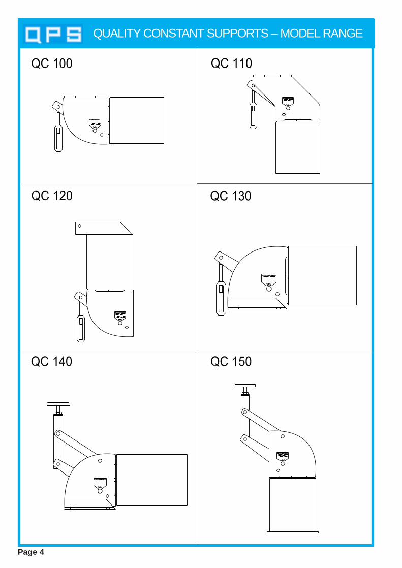
QUALITY CONSTANT SUPPORTS – MODEL RANGE
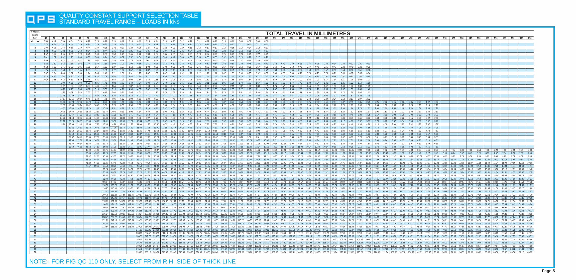
QUALITY CONSTANT SUPPORT SELECTION TABLE STANDARD TRAVEL RANGE – LOADS IN kNs
NOTE:- FOR FIG QC 110 ONLY, SELECT FROM R.H. SIDE OF THICK LINEPage 5
ConstantSpringSize 40 50 60 70 80 90 100 110 120 130 140 150 160 170 180 190 200 210 220 230 240 250 260 270 280 290 300 310 320 330 340 350 360 370 380 390 400 410 420 430 440 450 460 470 480 490 500 510 520 530 540 550 560 570 580 590 600 610
Min Load 0.59 0.49 0.39 0.34 0.29 0.27 0.25 0.22 0.20 0.19 0.18 0.16 0.15 0.14 0.14 0.13 0.12 0.12 0.11 0.11 0.10 0.10 0.10 0.09 0.09 0.09 0.081 0.78 0.64 0.51 0.44 0.39 0.34 0.29 0.27 0.25 0.24 0.22 0.21 0.20 0.18 0.17 0.16 0.15 0.14 0.14 0.13 0.13 0.12 0.12 0.11 0.11 0.11 0.102 0.98 0.78 0.66 0.56 0.49 0.44 0.39 0.35 0.32 0.30 0.28 0.26 0.25 0.23 0.22 0.21 0.20 0.18 0.18 0.17 0.17 0.16 0.15 0.15 0.14 0.14 0.133 1.23 0.98 0.83 0.71 0.62 0.54 0.49 0.44 0.41 0.38 0.35 0.33 0.31 0.29 0.27 0.26 0.25 0.24 0.23 0.22 0.21 0.20 0.20 0.19 0.18 0.17 0.174 1.57 1.27 1.05 0.90 0.79 0.71 0.63 0.58 0.53 0.49 0.45 0.42 0.39 0.37 0.35 0.33 0.31 0.29 0.28 0.27 0.26 0.25 0.25 0.24 0.23 0.22 0.215 2.01 1.62 1.32 1.15 1.00 0.88 0.80 0.74 0.67 0.62 0.57 0.54 0.50 0.47 0.44 0.42 0.40 0.38 0.36 0.35 0.33 0.32 0.31 0.29 0.28 0.27 0.266 2.55 2.06 1.72 1.47 1.27 1.13 1.03 0.93 0.85 0.78 0.74 0.69 064 0.59 0.57 0.54 0.51 0.49 0.46 0.44 0.42 0.41 0.39 0.37 0.36 0.35 0.347 3.24 2.60 2.16 1.86 1.62 1.44 1.30 1.18 1.08 1.00 0.93 0.86 0.81 0.76 0.74 0.69 0.64 0.62 0.59 0.57 0.54 0.52 0.50 0.48 0.46 0.45 0.43 0.42 0.41 0.39 0.38 0.37 0.36 0.35 0.34 0.33 0.32 0.31 0.318 4.12 3.29 2.75 2.35 2.06 1.81 1.67 1.52 1.37 1.27 1.18 1.10 1.03 0.98 0.93 0.88 0.83 0.78 0.76 0.73 0.69 0.67 0.64 0.62 0.59 0.57 0.55 0.54 0.52 0.50 0.49 0.47 0.46 0.45 0.43 0.42 0.41 0.40 0.399 5.25 4.22 3.53 2.99 2.65 2.35 2.11 1.91 1.77 1.62 1.52 1.42 1.32 1.23 1.18 1.13 1.03 0.98 0.96 0.91 0.88 0.84 0.81 0.78 0.76 0.73 0.71 0.68 0.66 0.64 0.62 0.60 0.59 0.57 0.56 0.54 0.53 0.51 0.50
10 6.67 5.34 4.46 3.82 3.33 2.94 2.65 2.40 2.21 2.06 1.91 1.77 1.67 1.57 1.47 1.42 1.32 1.27 1.22 1.16 1.11 1.07 1.03 0.99 0.95 0.92 0.89 0.86 0.83 0.80 0.78 0.76 0.75 0.73 0.71 0.69 0.67 0.65 0.6411 8.48 6.77 5.64 4.85 4.22 3.78 3.38 3.09 2.84 2.60 2.40 2.26 2.11 2.01 1.86 1.77 1.72 1.62 1.54 1.47 1.41 1.35 1.30 1.26 1.22 1.17 1.13 1.10 1.06 1.03 1.00 0.97 0.94 0.92 0.89 0.87 0.85 0.82 0.8012 10.74 8.58 7.16 6.13 5.39 4.76 4.31 3.92 3.58 3.29 3.09 2.84 2.70 2.55 2.40 2.26 2.16 2.06 1.96 1.87 1.79 1.73 1.66 1.60 1.54 1.48 1.43 1.39 1.34 1.30 1.27 1.23 1.20 1.17 1.14 1.11 1.08 1.05 1.0313 8.09 6.91 6.08 5.39 4.85 4.41 4.02 3.73 3.48 3.24 3.04 2.84 2.70 2.55 2.45 2.30 2.21 2.11 2.01 1.96 1.86 1.79 1.73 1.67 1.62 1.56 1.51 1.47 1.42 1.38 1.34 1.31 1.27 1.25 1.22 1.19 1.1614 9.07 7.80 6.82 6.08 5.44 4.95 4.56 4.22 3.87 3.63 3.43 3.24 3.04 2.89 2.75 2.60 2.50 2.35 2.26 2.21 2.11 2.02 1.95 1.88 1.81 1.76 1.71 1.66 1.60 1.56 1.51 1.47 1.43 1.40 1.36 1.33 1.2915 10.20 8.78 7.65 6.82 6.13 5.59 5.10 4.71 4.36 4.07 3.82 3.58 3.38 3.24 3.04 2.94 2.79 2.65 2.55 2.45 2.35 2.27 2.19 2.11 2.04 1.97 1.91 1.85 1.80 1.75 1.70 1.66 1.61 1.57 1.53 1.49 1.4616 11.28 9.69 8.48 7.55 6.77 6.18 5.64 5.20 4.85 4.51 4.22 3.97 3.78 3.58 3.38 3.24 3.09 2.94 2.84 2.70 2.60 2.51 2.42 2.33 2.26 2.19 2.12 2.05 1.99 1.93 1.88 1.83 1.78 1.74 1.70 1.66 1.6217 12.45 10.69 9.37 8.29 7.50 6.82 6.23 5.79 5.34 5.00 4.71 4.41 4.17 3.92 3.73 3.58 3.38 3.24 3.14 2.99 2.89 2.78 2.68 2.58 2.49 2.41 2.33 2.27 2.20 2.14 2.08 2.02 1.97 1.92 1.87 1.82 1.7818 14.17 12.16 10.64 9.46 8.48 7.75 7.06 6.52 6.08 5.69 5.30 5.00 4.71 4.46 4.27 4.07 3.87 3.68 3.53 3.40 3.29 3.15 3.03 2.93 2.83 2.74 2.66 2.57 2.50 2.42 2.36 2.29 2.24 2.18 2.13 2.07 2.0219 16.08 13.78 12.06 10.74 9.66 8.78 8.04 7.45 6.86 6.42 6.03 5.69 5.39 5.05 4.81 4.61 4.36 4.22 4.02 3.87 3.73 3.58 3.43 3.33 3.24 3.09 2.99 2.94 2.84 2.75 2.65 2.61 2.54 2.47 2.41 2.35 2.29 2.25 2.20 2.15 2.10 2.05 2.01 1.97 1.9320 17.50 15.00 13.14 11.67 10.49 9.56 8.78 8.09 7.50 7.01 6.57 6.18 5.83 5.54 5.25 5.00 4.81 4.56 4.36 4.22 4.02 3.87 3.78 3.63 3.48 3.38 3.29 3.19 3.09 2.99 2.94 2.83 2.77 2.70 2.63 2.56 2.50 2.44 2.38 2.33 2.28 2.24 2.19 2.15 2.1021 19.07 16.33 14.32 12.70 11.42 10.40 9.51 8.78 8.19 7.60 7.16 6.72 6.37 6.03 5.74 5.44 5.20 4.95 4.76 4.56 4.41 4.22 4.07 3.92 3.82 3.68 3.58 3.48 3.38 3.29 3.19 3.09 3.01 2.93 2.86 2.79 2.73 2.66 2.60 2.54 2.48 2.43 2.38 2.33 2.2822 20.79 17.85 15.59 13.88 12.50 11.33 10.40 9.61 8.92 8.34 7.80 7.36 6.96 6.57 6.23 5.93 5.69 5.44 5.20 5.00 4.81 4.61 4.46 4.31 4.17 4.02 3.92 3.78 3.68 3.58 3.48 3.37 3.29 3.20 3.12 3.04 2.97 2.90 2.83 2.78 2.72 2.66 2.60 2.55 2.5023 22.70 19.47 17.01 15.15 13.63 12.41 11.38 10.49 9.71 9.07 8.53 8.04 7.55 7.16 6.82 6.47 6.18 5.93 5.69 5.44 5.25 5.05 4.85 4.71 4.56 4.41 4.27 4.12 4.02 3.87 3.78 3.68 3.59 3.49 3.40 3.32 3.25 3.17 3.10 3.03 2.96 2.90 2.83 2.78 2.7324 24.66 21.13 18.53 16.43 14.81 13.44 12.36 11.38 10.59 9.86 9.27 8.73 8.24 7.80 7.40 7.06 6.72 6.42 6.18 5.93 5.69 5.49 5.30 5.10 4.95 4.76 4.61 4.46 4.36 4.22 4.12 4.00 3.89 3.80 3.71 3.61 3.53 3.44 3.36 3.30 3.22 3.15 3.09 3.02 2.9625 27.12 23.24 20.35 18.09 16.28 14.81 13.58 12.50 11.62 10.84 10.15 9.56 9.02 8.58 8.14 7.75 7.40 7.06 6.77 6.52 6.28 6.03 5.83 5.59 5.44 5.25 5.10 4.90 4.81 4.66 4.51 4.39 4.29 4.17 4.07 3.97 3.87 3.79 3.70 3.62 3.54 3.46 3.39 3.32 3.2626 29.96 25.69 22.46 19.96 17.95 16.33 14.96 13.83 12.85 11.96 11.23 10.57 10.00 9.46 8.97 8.53 8.19 7.80 7.50 7.21 6.91 6.67 6.42 6.18 5.98 5.79 5.64 5.44 5.30 5.15 5.00 4.85 4.73 4.61 4.49 4.38 4.28 4.18 4.08 3.99 3.90 3.82 3.75 3.67 3.5927 29.22 25.60 22.75 20.45 18.58 17.06 15.74 14.61 13.63 12.75 12.01 11.38 10.79 10.25 9.76 9.32 8.92 8.53 8.19 7.85 7.55 7.31 7.06 6.82 6.62 6.37 6.18 6.03 5.83 5.69 5.53 5.38 5.25 5.11 4.99 4.86 4.76 4.65 4.54 4.44 4.35 4.26 4.18 4.0928 33.10 28.93 25.74 23.14 21.04 19.32 17.80 16.52 15.45 14.46 13.63 12.85 12.21 11.57 11.03 10.54 10.10 9.66 9.27 8.92 8.58 8.29 7.99 7.70 7.45 7.26 7.01 6.82 6.62 6.42 6.26 6.10 5.94 5.80 5.65 5.51 5.38 5.27 5.15 5.04 4.93 4.82 4.73 4.6329 36.19 31.63 28.15 25.30 23.00 21.08 19.47 18.09 16.87 15.84 14.91 14.07 13.34 12.65 12.06 11.52 10.98 10.54 10.10 9.76 9.37 9.02 8.73 8.43 8.14 7.94 7.65 7.45 7.21 7.01 6.85 6.66 6.49 6.33 6.18 6.03 5.88 5.76 5.63 5.50 5.38 5.28 5.17 5.0630 39.37 34.47 30.65 27.56 25.06 23.00 21.18 19.71 18.39 17.21 16.23 15.30 14.51 13.78 13.14 12.55 11.96 11.47 11.03 10.59 10.20 9.86 9.51 9.22 8.92 8.63 8.34 8.09 7.89 7.65 7.45 7.26 7.07 6.89 6.73 6.56 6.41 6.27 6.13 5.99 5.86 5.75 5.63 5.5131 42.95 37.56 33.39 30.06 27.31 25.06 23.09 21.48 20.05 18.78 17.70 16.67 15.84 15.00 14.32 13.68 13.04 12.50 12.01 11.57 11.13 10.74 10.35 10.00 9.71 9.41 9.12 8.83 8.58 8.34 8.12 7.91 7.71 7.51 7.34 7.16 6.99 6.84 6.68 6.53 6.39 6.27 6.14 6.0132 46.83 40.94 36.38 32.75 29.76 27.31 25.20 23.39 21.82 20.50 19.27 18.19 17.26 16.38 15.59 14.91 14.27 13.63 13.09 12.60 12.11 11.72 11.28 10.93 10.59 10.25 9.90 9.66 9.37 9.12 8.86 8.62 8.40 8.19 7.99 7.80 7.62 7.44 7.28 7.12 6.97 6.83 6.69 6.5533 53.59 46.88 41.68 37.51 34.08 31.28 28.83 26.77 25.01 23.44 22.07 20.84 19.76 18.78 17.85 17.06 16.33 15.64 15.00 14.42 13.88 13.39 12.94 12.50 12.11 11.72 11.38 11.03 10.74 10.44 10.14 9.88 9.62 9.38 9.15 8.93 8.73 8.52 8.34 8.16 7.98 7.82 7.66 7.5034 46.09 41.48 37.71 34.57 31.92 29.62 27.65 25.94 24.37 23.05 21.82 20.74 19.76 18.83 18.04 17.26 16.57 15.94 15.35 14.81 14.32 13.83 13.39 12.94 12.55 12.21 11.87 11.52 11.23 10.93 10.64 10.35 10.10 9.88 9.64 9.42 9.22 9.01 8.83 8.64 8.46 8.30 8.13 7.97 7.83 7.68 7.54 7.40 7.28 7.15 7.03 6.91 6.8035 50.46 45.41 41.29 37.85 34.96 32.46 30.30 28.39 26.72 25.25 23.93 22.70 21.62 20.64 19.76 18.93 18.19 17.46 16.82 16.23 15.69 15.15 14.66 14.17 13.78 13.34 12.99 12.60 12.26 11.96 11.67 11.38 11.08 10.82 10.56 10.33 10.09 9.88 9.67 9.46 9.27 9.43 8.90 8.74 8.57 8.41 8.26 8.11 7.97 7.84 7.70 7.57 7.4436 57.37 51.63 46.93 43.05 39.72 36.87 34.42 32.26 30.35 28.68 27.16 25.84 24.57 23.49 22.46 21.53 20.64 19.86 19.12 18.44 17.80 17.21 16.67 16.13 15.64 15.20 14.76 14.37 13.93 13.58 13.24 12.90 12.60 12.30 12.00 11.74 11.47 11.23 10.98 10.76 10.53 10.33 10.12 9.93 9.74 9.56 9.39 9.22 9.06 8.90 8.75 8.59 8.4637 65.26 58.74 53.40 48.98 45.21 41.97 39.17 36.73 34.57 32.66 30.94 29.37 28.00 26.72 25.55 24.47 23.49 22.60 21.77 20.99 20.25 19.56 18.98 18.34 17.80 17.26 16.77 16.33 15.89 15.45 15.05 14.71 14.32 13.98 13.66 13.36 13.05 12.77 12.50 12.24 11.99 11.75 11.52 11.30 11.08 10.88 10.68 10.49 10.31 10.13 9.95 9.80 9.6338 71.20 64.09 58.25 53.40 49.28 45.75 42.71 40.06 37.71 35.60 33.74 32.02 30.50 29.13 27.85 26.67 25.64 24.66 23.73 22.90 22.11 21.38 20.69 20.01 19.42 18.83 18.29 17.80 17.31 16.87 16.43 16.03 15.64 15.25 14.90 14.56 14.24 13.93 13.63 13.35 13.07 12.82 12.56 12.32 12.09 11.87 11.65 11.44 11.24 11.04 10.86 10.68 10.5039 77.57 69.82 63.50 58.20 53.69 49.87 46.53 43.64 41.09 38.79 36.78 34.91 33.24 31.72 30.35 29.08 27.95 26.87 25.89 24.96 24.08 23.29 22.51 22.07 21.18 20.55 19.96 19.42 18.88 18.39 17.90 17.46 17.01 16.62 16.24 15.87 15.51 15.18 14.86 14.54 14.25 13.96 13.69 13.43 13.17 12.94 12.70 12.46 12.25 12.04 11.84 11.64 11.4440 69.24 63.45 58.60 54.38 50.75 47.61 44.82 42.32 40.06 38.10 36.28 34.62 33.10 31.72 30.45 29.27 28.19 27.21 26.28 25.40 24.57 23.78 23.09 22.41 21.77 21.18 20.59 20.05 19.52 19.02 18.58 18.13 17.71 17.31 16.93 16.55 16.20 15.87 15.54 15.23 14.94 14.64 14.37 14.10 13.85 13.60 13.36 13.13 12.91 12.69 12.4841 75.36 69.09 63.79 59.23 55.26 51.83 48.79 46.09 43.64 41.48 39.47 37.71 36.04 34.57 33.15 31.87 30.69 29.62 28.59 27.65 26.77 25.89 25.11 24.37 23.68 23.05 22.41 21.82 21.28 20.74 20.20 19.74 19.28 18.85 18.43 18.02 17.64 17.28 16.93 16.58 16.26 15.95 15.64 15.36 15.07 14.81 14.54 14.30 14.05 13.82 13.5942 82.57 75.71 69.87 64.87 60.56 56.78 53.45 50.46 47.81 45.41 43.25 41.29 39.52 37.85 36.33 34.96 33.64 32.41 31.33 30.30 29.32 28.39 27.51 26.72 25.94 25.25 24.57 23.93 23.29 22.70 22.16 21.63 21.12 20.64 20.19 19.75 19.33 18.93 18.53 18.17 17.81 16.85 17.14 16.82 16.51 16.22 15.94 15.66 15.40 15.14 14.9043 93.90 86.05 79.43 73.75 68.84 64.53 60.75 57.37 54.33 51.63 49.18 46.93 44.91 43.05 41.29 39.72 38.25 36.87 35.60 34.42 33.29 32.26 31.28 30.35 29.52 28.68 27.90 27.16 26.48 25.84 25.20 24.59 24.02 23.47 22.95 22.45 21.98 21.52 21.07 20.65 20.25 19.86 19.49 19.12 18.78 18.44 18.11 17.81 17.50 17.21 16.9344 106.84 97.92 90.37 83.95 78.36 73.45 69.14 65.26 61.83 58.74 55.95 53.40 51.09 48.98 47.02 45.21 43.54 41.97 40.50 39.18 37.90 36.73 35.60 34.57 33.59 32.66 31.77 30.94 30.11 29.37 28.68 27.98 27.33 26.70 26.12 25.55 25.00 24.48 23.98 23.50 23.04 22.59 22.17 21.76 21.37 20.99 20.61 20.26 19.92 19.58 19.2645 116.50 106.79 98.56 91.50 85.42 80.07 75.36 71.20 67.42 64.04 61.00 58.25 55.70 53.40 51.24 49.28 47.46 45.75 44.18 42.71 41.34 40.06 38.83 37.71 36.63 35.60 34.62 33.74 32.85 32.02 31.23 30.51 29.79 29.12 28.47 27.85 27.26 26.69 26.14 25.62 25.12 24.64 24.17 23.73 23.30 22.88 22.48 22.09 21.71 21.36 21.0146 126.95 116.36 107.43 99.73 93.11 87.28 82.13 77.57 73.50 69.82 66.49 63.50 60.70 58.20 55.85 53.69 51.73 49.87 48.15 46.53 45.06 43.64 42.32 41.09 39.91 38.79 37.76 36.78 35.79 34.91 34.08 33.25 32.48 31.73 31.04 30.36 29.71 29.10 28.50 27.93 26.76 26.86 26.35 25.86 25.39 24.94 24.50 24.08 23.67 23.27 22.9047 138.47 126.90 117.14 108.81 101.55 95.17 89.58 84.63 80.17 76.15 72.52 69.24 66.24 63.45 60.90 58.60 56.39 54.38 52.51 50.75 49.13 47.61 46.14 44.82 43.49 42.32 41.19 40.06 39.03 38.10 37.17 36.27 35.42 34.62 33.84 33.11 32.40 31.73 31.09 30.46 29.86 29.29 28.73 28.20 27.69 27.19 26.72 26.26 25.81 25.38 24.9748 150.78 138.23 127.59 118.46 110.57 103.71 97.58 92.13 87.28 82.92 78.99 75.41 72.13 69.09 66.34 63.79 61.44 59.23 57.17 55.31 53.50 51.83 50.26 48.79 47.37 46.09 44.82 43.64 42.51 41.48 40.45 39.49 38.57 37.70 36.86 36.06 35.29 34.56 33.85 32.69 32.52 31.90 31.29 30.71 30.16 29.62 29.10 28.60 28.12 27.65 27.1949 162.79 149.21 137.74 127.93 119.40 111.94 105.32 99.49 94.24 89.54 85.27 81.40 77.87 74.63 71.64 68.89 66.34 63.94 61.73 59.67 57.76 55.95 54.28 52.66 51.19 49.77 48.40 47.12 45.90 44.77 43.69 42.64 41.65 40.70 39.80 38.93 38.10 37.30 36.55 35.81 35.12 34.44 33.79 33.17 32.56 31.98 31.42 30.88 30.35 29.85 29.3650 176.67 161.96 149.50 138.81 129.55 121.46 114.30 107.97 102.28 97.18 92.53 88.36 84.48 80.95 77.77 74.73 71.98 69.38 67.03 64.77 62.71 60.75 58.89 57.17 55.55 53.99 52.51 51.14 49.82 48.59 47.42 46.27 45.20 44.17 43.19 42.25 41.35 40.49 39.66 38.86 38.11 37.37 36.67 35.99 35.33 34.71 34.10 33.51 32.94 32.39 31.8651 190.00 174.17 160.78 149.31 139.35 130.63 122.98 116.11 110.03 104.54 99.54 95.03 90.56 87.08 83.60 80.41 77.42 74.63 72.08 69.68 67.42 65.31 63.35 61.49 59.72 58.06 56.49 55.02 53.59 52.27 50.99 49.77 48.61 47.50 46.45 45.44 44.47 43.55 42.66 41.81 40.98 40.20 39.44 38.71 38.00 37.32 36.67 36.04 35.43 34.83 34.2652 205.45 188.29 173.82 161.42 150.63 141.22 132.93 125.53 118.96 112.97 107.63 102.73 98.26 94.14 90.37 86.94 83.70 80.71 77.91 75.32 72.91 70.61 68.45 66.44 64.58 62.76 61.10 59.48 57.96 56.49 55.11 53.80 52.55 51.36 50.22 49.12 48.08 47.08 46.12 45.20 44.31 43.45 42.64 41.85 41.09 40.35 39.65 38.96 38.30 37.66 37.0553 221.88 203.39 187.75 174.31 162.69 152.54 143.57 135.58 128.42 122.04 116.21 110.91 106.11 101.70 97.63 93.85 90.37 87.18 84.14 81.35 78.70 76.05 73.94 71.79 69.73 67.81 65.95 64.23 62.57 61.00 59.53 58.10 56.76 55.47 54.23 53.05 51.93 50.85 49.81 48.81 47.86 46.93 46.05 45.20 44.38 43.58 42.82 42.08 41.36 40.68 40.0154 236.24 216.58 199.91 185.59 173.24 162.40 152.89 144.35 136.75 129.94 123.76 118.12 112.97 108.27 103.95 99.93 96.30 92.82 89.63 86.64 83.80 81.20 78.75 76.44 74.24 72.18 70.22 68.40 66.64 64.97 63.40 61.87 60.44 59.07 57.75 56.50 55.29 54.14 53.03 51.98 50.96 49.97 49.03 48.12 47.25 46.41 45.59 44.81 44.04 43.32 42.6055 253.41 232.27 214.42 199.08 185.84 174.22 163.97 154.85 146.71 139.35 132.73 126.70 121.16 116.16 111.50 107.19 103.22 99.54 96.11 92.92 89.93 87.08 84.48 81.98 79.63 77.42 75.32 73.35 71.49 69.68 67.96 66.36 64.82 63.35 61.94 60.60 59.30 58.07 56.88 55.74 54.65 53.60 52.59 51.61 50.68 49.77 48.90 48.05 47.24 46.45 45.6956 271.79 249.13 229.97 213.54 199.32 186.87 175.83 166.08 157.35 149.45 142.34 135.87 129.99 124.55 119.59 114.98 110.72 106.75 103.07 99.64 96.45 93.41 90.61 87.92 85.42 83.06 80.81 78.65 76.64 74.73 72.91 71.18 69.52 67.94 66.43 64.99 63.61 62.28 61.01 59.79 58.61 57.49 56.41 55.36 54.36 53.39 52.45 51.54 50.67 49.83 49.0057 291.50 267.18 246.64 229.04 213.74 200.40 188.58 178.14 168.77 160.34 152.69 145.73 139.40 133.62 128.27 123.33 118.76 114.49 110.57 106.89 103.41 100.22 97.18 94.29 91.59 89.04 86.64 84.34 82.23 80.17 78.21 76.35 74.57 72.87 71.26 69.71 68.23 66.80 65.44 64.13 62.87 61.66 60.50 59.38 58.30 57.26 56.25 55.28 54.35 53.44 52.5658 312.64 286.60 264.54 245.66 229.28 214.96 202.31 191.08 180.98 171.96 163.77 156.32 149.50 143.28 137.54 132.29 127.39 122.83 118.56 114.64 110.91 107.48 104.20 101.16 98.26 95.52 92.97 90.47 88.16 85.96 83.90 81.89 79.97 78.16 76.42 74.77 73.17 71.65 70.19 68.78 67.43 66.14 64.89 63.68 62.53 61.41 60.33 59.29 58.29 57.32 56.3859 241.03 225.95 212.66 200.84 190.30 180.79 172.16 164.36 157.20 150.63 144.60 139.06 133.91 129.11 124.69 120.52 116.65 112.97 109.54 106.35 103.31 100.42 97.72 95.12 92.72 90.37 88.16 86.08 84.08 82.17 80.35 78.60 76.92 75.33 73.79 72.30 70.89 69.53 68.22 66.95 65.73 64.56 63.43 62.33 61.28 60.25 59.2760 253.39 237.57 223.59 211.14 200.06 190.05 180.98 172.75 165.24 158.38 152.05 146.17 140.78 135.72 131.07 126.70 122.63 118.76 115.18 111.80 108.61 105.57 102.73 100.03 97.48 95.03 92.72 90.50 88.39 86.39 84.47 82.63 80.87 79.19 77.57 76.02 74.53 73.09 71.72 70.38 69.11 67.87 66.69 65.53 64.42 63.35 62.3161 266.39 249.73 235.07 221.97 210.30 199.81 190.30 181.62 173.73 166.52 159.85 153.67 147.98 142.69 137.78 133.17 128.91 124.89 121.06 117.53 114.15 111.01 107.97 105.18 102.48 99.88 97.48 95.13 92.93 90.81 88.80 86.87 85.01 83.25 81.54 79.91 78.35 76.85 75.39 74.00 72.65 71.35 70.10 68.89 67.73 66.60 65.5162 280.05 262.53 247.13 233.40 221.09 210.06 200.06 190.94 182.65 175.05 168.04 161.57 155.58 150.04 144.84 140.04 135.53 131.26 127.29 123.56 120.03 116.70 113.51 110.57 107.73 105.03 102.48 100.02 97.69 95.47 93.35 91.32 89.38 87.51 85.73 84.01 82.37 80.79 79.26 77.80 76.37 75.01 73.70 72.42 71.20 70.01 68.8663 291.48 273.26 257.18 242.91 230.11 218.59 208.20 198.73 190.10 182.16 174.90 168.18 161.91 156.17 150.78 145.73 141.02 136.61 132.49 128.61 124.94 121.46 118.17 115.03 112.09 109.30 106.65 104.10 101.69 99.37 97.16 95.05 93.03 91.09 89.23 87.45 85.73 84.08 82.49 80.96 79.49 78.08 76.71 75.38 74.11 72.87 71.6864 303.39 284.44 267.67 252.82 239.53 227.56 216.73 206.87 197.85 189.61 182.01 175.05 168.53 162.55 156.91 151.71 146.81 142.20 137.88 133.86 130.04 126.41 122.98 119.74 116.70 113.76 111.01 108.35 105.83 103.43 101.13 98.93 96.82 94.81 92.87 91.02 89.23 87.51 85.87 84.28 82.74 81.27 79.84 78.46 77.13 75.85 74.6065 315.78 296.02 278.61 263.16 249.29 236.83 225.55 215.31 205.94 197.36 189.47 182.16 175.44 169.17 163.33 157.89 152.79 148.03 143.52 139.30 135.33 131.61 128.03 124.64 121.46 118.42 115.52 112.78 110.16 107.65 105.26 102.97 100.78 98.68 96.66 94.73 92.88 91.08 89.37 87.71 86.12 84.58 83.10 81.67 80.28 78.94 77.6566 328.67 308.13 289.98 273.90 259.49 246.49 234.77 224.08 214.33 205.40 197.21 189.61 182.60 176.08 170.00 164.31 159.02 154.06 149.41 144.99 140.87 136.95 133.22 129.74 126.41 123.27 120.23 117.38 114.65 112.04 109.56 107.18 104.89 102.71 100.62 98.60 96.66 94.81 96.55 91.30 89.63 88.03 86.50 85.00 83.56 82.17 80.82
TOTAL TRAVEL IN MILLIMETRES
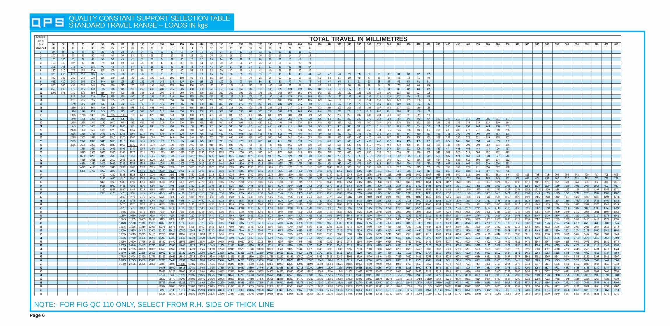
QUALITY CONSTANT SUPPORT SELECTION TABLE STANDARD TRAVEL RANGE – LOADS IN kgs
NOTE:- FOR FIG QC 110 ONLY, SELECT FROM R.H. SIDE OF THICK LINEPage 6
ConstantSpringSize 40 50 60 70 80 90 100 110 120 130 140 150 160 170 180 190 200 210 220 230 240 250 260 270 280 290 300 310 320 330 340 350 360 370 380 390 400 410 420 430 440 450 460 470 480 490 500 510 520 530 540 550 560 570 580 590 600 610
Min Load 60 50 40 35 30 28 25 22 20 19 18 16 15 14 14 13 12 12 11 11 10 10 10 9 9 9 81 80 65 52 45 40 35 30 28 26 24 22 21 20 18 17 16 15 14 14 13 13 12 12 11 11 11 102 100 80 67 57 50 45 40 36 33 31 29 27 25 23 22 21 20 18 18 17 17 16 15 15 14 14 133 125 100 85 72 63 55 50 45 42 39 36 34 32 30 28 27 25 24 23 22 21 20 20 19 18 17 174 160 130 107 92 81 72 64 59 54 50 46 43 40 38 36 34 32 30 29 28 27 26 25 24 23 22 215 205 165 135 117 102 90 82 75 68 63 58 55 51 48 45 43 41 39 37 36 34 33 32 30 29 28 276 260 210 175 150 130 115 105 95 87 80 75 70 65 60 58 55 52 50 47 45 43 42 40 38 37 36 357 330 265 220 190 165 147 133 120 110 102 95 88 83 78 75 70 65 63 60 58 55 53 51 49 47 46 44 43 42 40 39 38 37 36 35 34 33 32 328 420 335 280 240 210 185 170 155 140 130 120 112 105 100 95 90 85 80 77 74 70 68 65 63 60 58 56 55 53 51 50 48 47 46 44 43 42 41 409 535 430 360 305 270 240 215 195 180 165 155 145 135 125 120 115 105 100 98 93 90 86 83 80 77 74 72 69 67 65 63 61 60 58 57 55 54 52 51
10 680 545 455 390 340 300 270 245 225 210 195 180 170 160 150 145 135 130 124 118 113 109 105 101 97 94 91 88 85 82 80 78 76 74 72 70 68 66 6511 865 690 575 495 430 385 345 315 290 265 245 230 215 205 190 180 175 165 157 150 144 138 133 128 124 119 115 112 108 105 102 99 96 94 91 89 87 84 8212 1095 875 730 625 550 485 440 400 365 335 315 290 275 260 245 230 220 210 200 191 183 176 169 163 157 151 146 142 137 133 129 125 122 119 116 113 110 107 10513 825 705 620 550 495 450 410 380 355 330 310 290 275 260 250 235 225 215 205 200 190 183 176 170 165 159 154 150 145 141 137 134 130 127 124 121 11814 925 795 695 620 555 505 465 430 395 370 350 330 310 295 280 265 255 240 230 225 215 206 199 192 185 179 174 169 163 159 154 150 146 143 139 136 13215 1040 895 780 695 625 570 520 480 445 415 390 365 345 330 310 300 285 270 260 250 240 231 223 215 208 201 195 189 184 178 173 169 164 160 156 152 14916 1150 988 865 770 690 630 575 530 495 460 430 405 385 365 345 330 315 300 290 275 265 256 247 238 230 223 216 209 203 197 192 187 182 177 173 169 16517 1270 1090 955 845 765 695 635 590 545 510 480 450 425 400 380 365 345 330 320 305 295 283 273 263 254 246 238 231 224 218 212 206 201 196 191 186 18218 1445 1240 1085 965 865 790 720 665 620 580 540 510 480 455 435 415 395 375 360 347 335 321 309 299 289 279 271 262 255 247 241 234 228 222 217 211 20619 1640 1405 1230 1095 985 895 820 760 700 655 615 580 550 515 490 470 445 430 410 395 380 365 350 340 330 315 305 300 290 280 270 266 259 252 246 240 234 229 224 219 214 209 205 201 19720 1785 1530 1340 1190 1070 975 895 825 765 715 670 630 595 565 535 510 490 465 445 430 410 395 385 370 355 345 335 325 315 305 300 289 282 275 268 261 255 249 243 238 233 228 223 219 21421 1945 1665 1460 1295 1165 1060 970 895 835 775 730 685 650 615 585 555 530 505 485 465 450 430 415 400 390 375 365 355 345 335 325 315 307 299 292 284 278 271 265 259 253 248 243 238 23322 2120 1820 1590 1415 1275 1155 1060 980 910 850 795 750 710 670 635 605 580 555 530 510 490 470 455 440 425 410 400 385 375 365 355 344 335 326 318 310 303 296 289 283 277 271 265 260 25523 2315 1985 1735 1545 1390 1265 1160 1070 990 925 870 820 770 730 695 660 630 605 580 555 535 515 495 480 465 450 435 420 410 395 385 375 366 356 347 339 331 323 316 309 302 296 289 283 27824 2515 2155 1890 1675 1510 1370 1260 1160 1080 1005 945 890 840 795 755 720 685 655 630 605 580 560 540 520 505 485 470 455 445 430 420 408 397 387 378 368 360 351 343 336 328 321 315 308 30225 2765 2370 2075 1845 1660 1510 1385 1275 1185 1105 1035 975 920 875 830 790 755 720 690 665 640 615 595 570 555 535 520 500 490 475 460 448 437 425 415 405 395 386 377 369 361 353 346 339 33226 3055 2620 2290 2035 1830 1665 1525 1410 1310 1220 1145 1078 1020 965 915 870 835 795 765 735 705 680 655 630 610 590 575 555 540 525 510 495 482 470 458 447 436 426 416 407 398 390 382 374 36627 2980 2610 2320 2085 1895 1740 1605 1490 1390 1300 1225 1160 1100 1045 995 950 910 870 835 800 770 745 720 695 675 650 630 615 595 580 564 549 535 521 509 496 485 474 463 453 444 434 426 41728 3375 2950 2625 2360 2145 1970 1815 1685 1575 1475 1390 1310 1245 1180 1125 1075 1030 985 945 910 875 845 815 785 760 740 715 695 675 655 638 622 606 591 576 562 549 537 525 514 503 492 482 47229 3690 3225 2870 2580 2345 2150 1985 1845 1720 1615 1520 1435 1360 1290 1230 1175 1120 1075 1030 995 955 920 890 860 830 810 780 760 735 715 698 679 662 645 630 615 600 587 574 561 549 538 527 51630 4015 3515 3125 2810 2555 2345 2160 2010 1875 1755 1655 1560 1480 1405 1340 1280 1220 1170 1125 1080 1040 1005 970 940 910 880 850 825 805 780 760 740 721 703 686 669 654 639 625 611 598 586 574 56231 4380 3830 3405 3065 2785 2555 2355 2190 2045 1915 1805 1700 1615 1530 1460 1395 1330 1275 1225 1180 1135 1095 1055 1020 990 960 930 900 875 850 828 807 786 766 748 730 713 697 681 666 652 639 626 61332 4775 4175 3710 3340 3035 2785 2570 2385 2225 2090 1965 1855 1760 1670 1590 1520 1455 1390 1335 1285 1235 1195 1150 1115 1080 1045 1010 985 955 930 903 879 857 835 815 795 777 759 742 726 711 696 682 66833 5465 4780 4250 3825 3475 3190 2940 2730 2550 2390 2250 2125 2015 1915 1820 1740 1665 1595 1530 1470 1415 1365 1320 1275 1235 1195 1160 1125 1095 1065 1034 1007 981 956 933 911 890 869 850 832 814 797 781 76534 4700 4230 3845 3525 3255 3020 2820 2645 2485 2350 2225 2115 2015 1920 1840 1760 1690 1625 1565 1510 1460 1410 1365 1320 1280 1245 1210 1175 1145 1115 1085 1055 1030 1007 983 961 940 919 900 881 863 846 829 813 798 783 769 755 742 729 717 705 69335 5145 4630 4210 3860 3565 3310 3090 2895 2725 2575 2440 2315 2205 2105 2015 1930 1855 1780 1715 1655 1600 1545 1495 1445 1405 1360 1325 1285 1250 1220 1190 1160 1130 1103 1077 1053 1029 1007 986 965 945 962 908 891 874 858 842 827 813 799 785 772 75936 5850 5265 4785 4390 4050 3760 3510 3290 3095 2925 2770 2635 2505 2395 2290 2195 2105 2025 1950 1880 1815 1755 1700 1645 1595 1550 1505 1465 1420 1385 1350 1315 1285 1254 1224 1197 1170 1145 1120 1097 1074 1053 1032 1013 993 975 957 940 924 908 892 876 86337 6655 5990 5445 4995 4610 4280 3994 3745 3525 3330 3155 2995 2855 2725 2605 2495 2395 2305 2220 2140 2065 1995 1935 1870 1815 1760 1710 1665 1620 1575 1535 1500 1460 1426 1393 1362 1331 1302 1275 1248 1223 1198 1175 1152 1130 1109 1089 1070 1051 1033 1015 999 98238 7260 6535 5940 5445 5025 4665 4355 4085 3845 3630 3440 3265 3110 2970 2840 2720 2615 2515 2420 2335 2255 2180 2110 2040 1980 1920 1865 1815 1765 1720 1675 1635 1595 1555 1519 1485 1452 1420 1390 1361 1333 1307 1281 1256 1233 1210 1188 1167 1146 1126 1107 1089 107139 7910 7120 6475 5935 5475 5085 4745 4450 4190 3955 3750 3560 3390 3235 3095 2965 2850 2740 2640 2545 2455 2375 2295 2250 2160 2095 2035 1980 1925 1875 1825 1780 1735 1695 1656 1618 1582 1548 1515 1483 1453 1424 1396 1369 1343 1319 1295 1271 1249 1228 1207 1187 116740 7060 6470 5975 5545 5175 4855 4570 4315 4085 3885 3700 3530 3375 3235 3105 2985 2875 2775 2680 2590 2505 2425 2355 2285 2220 2160 2100 2045 1990 1940 1895 1849 1806 1765 1726 1688 1652 1618 1585 1553 1523 1493 1465 1438 1412 1387 1362 1339 1316 1294 127341 7685 7045 6505 6040 5635 5285 4975 4700 4450 4230 4025 3845 3675 3525 3380 3250 3130 3020 2915 2820 2730 2640 2560 2485 2415 2350 2285 2225 2170 2115 2060 2013 1966 1922 1879 1838 1799 1762 1726 1691 1658 1626 1595 1566 1537 1510 1483 1458 1433 1409 138642 8420 7720 7125 6615 6175 5790 5450 5145 4875 4630 4410 4210 4030 3860 3705 3565 3430 3305 3195 3090 2990 2895 2805 2725 2645 2575 2505 2440 2375 2315 2260 2206 2154 2105 2059 2014 1971 1930 1890 1853 1816 1718 1748 1715 1684 1654 1625 1597 1570 1544 151943 9575 8775 8100 7520 7020 6580 6195 5850 5540 5265 5015 4785 4580 4390 4210 4050 3900 3760 3630 3510 3395 3290 3190 3095 3010 2925 2845 2770 2700 2635 2570 2507 2449 2393 2340 2289 2241 2194 2149 2106 2065 2025 1987 1950 1915 1880 1847 1816 1785 1755 172644 10895 9985 9215 8560 7990 7490 7050 6655 6305 5990 5705 5445 5210 4995 4795 4610 4440 4280 4130 3995 3865 3745 3630 3525 3425 3330 3240 3155 3070 2995 2925 2853 2787 2723 2663 2605 2549 2496 2445 2396 2349 2304 2261 2219 2179 2140 2102 2066 2031 1997 196445 11880 10890 10050 9330 8710 8165 7685 7260 6875 6530 6220 5940 5680 5445 5225 5025 4840 4665 4505 4355 4215 4085 3960 3845 3735 3630 3530 3440 3350 3265 3185 3111 3038 2969 2903 2840 2780 2722 2666 2613 2562 2513 2465 2420 2376 2333 2292 2253 2214 2178 214246 12945 11865 10955 10170 9495 8900 8375 7910 7495 7120 6780 6475 6190 5935 5695 5475 5275 5085 4910 4745 4595 4450 4315 4190 4070 3955 3850 3750 3650 3560 3475 3391 3312 3236 3165 3096 3030 2967 2906 2848 2729 2739 2687 2637 2589 2543 2498 2455 2414 2373 233547 14120 12940 11945 11095 10355 9705 9135 8630 8175 7765 7395 7060 6755 6470 6210 5975 5750 5545 5355 5175 5010 4855 4705 4570 4435 4315 4200 4085 3980 3885 3790 3698 3612 3530 3451 3376 3304 3236 3170 3106 3045 2987 2930 2876 2824 2773 2725 2678 2632 2588 254648 15375 14095 13010 12080 11275 10575 9950 9395 8900 8455 8055 7690 7355 7045 6765 6505 6265 6040 5830 5640 5455 5285 5125 4975 4830 4700 4570 4450 4335 4230 4125 4027 3933 3844 3759 3677 3599 3524 3452 3333 3316 3253 3191 3132 3075 3020 2967 2916 2867 2819 277349 16600 15215 14045 13045 12175 11415 10740 10145 9610 9130 8695 8300 7940 7610 7305 7025 6765 6520 6295 6085 5890 5705 5535 5370 5220 5075 4935 4805 4680 4565 4455 4348 4247 4150 4058 3970 3885 3804 3727 3652 3581 3512 3446 3382 3320 3261 3204 3149 3095 3044 299450 18015 16515 15245 14155 13210 12385 11655 11010 10430 9910 9435 9010 8615 8255 7930 7620 7340 7075 6835 6605 6395 6195 6005 5830 5665 5505 5355 5215 5080 4955 4835 4718 4609 4504 4404 4308 4216 4129 4044 3963 3886 3811 3739 3670 3603 3539 3477 3417 3359 3303 324951 19375 17760 16395 15225 14210 13320 12540 11840 11220 10660 10150 9690 9235 8880 8525 8200 7895 7610 7350 7105 6875 6660 6460 6270 6090 5920 5760 5610 5465 5330 5200 5075 4957 4844 4737 4635 4535 4441 4350 4263 4179 4099 4022 3947 3875 3806 3739 3675 3613 3552 349452 20950 19200 17725 16460 15360 14400 13555 12800 12130 11520 10975 10475 10020 9600 9215 8865 8535 8230 7945 7680 7435 7200 6980 6775 6585 6400 6230 6065 5910 5760 5620 5486 5359 5237 5121 5009 4903 4801 4703 4609 4518 4431 4348 4267 4190 4115 4043 3973 3906 3840 377853 22625 20740 19145 17775 16590 15555 14640 13825 13095 12445 11850 11310 10820 10370 9955 9570 9215 8890 8580 8295 8025 7755 7540 7320 7110 6915 6725 6550 6380 6220 6070 5925 5788 5656 5530 5410 5295 5185 5079 4977 4880 4786 4696 4609 4525 4444 4366 4291 4218 4148 408054 24090 22085 20385 18925 17665 16560 15590 14720 13945 13250 12620 12045 11520 11040 10600 10190 9820 9465 9140 8835 8545 8280 8030 7795 7570 7360 7160 6975 6795 6625 6465 6309 6163 6023 5889 5761 5638 5521 5408 5300 5196 5096 5000 4907 4818 4732 4649 4569 4491 4417 434455 25840 23685 21865 20300 18950 17765 16720 15790 14960 14210 13535 12920 12355 11845 11370 10930 10525 10150 9800 9475 9170 8880 8615 8360 8120 7895 7680 7480 7290 7105 6930 6767 6610 6460 6316 6179 6047 5921 5800 5684 5573 5466 5363 5263 5168 5075 4986 4900 4817 4737 465956 27715 25404 23450 21775 20325 19055 17930 16935 16045 15240 14515 13855 13255 12700 12195 11725 11290 10885 10510 10160 9835 9525 9240 8965 8710 8470 8240 8020 7815 7620 7435 7258 7089 6928 6774 6627 6486 6351 6221 6097 5977 5862 5752 5645 5543 5444 5348 5256 5167 5081 499757 29725 27245 25150 23355 21795 20435 19230 18165 17210 16350 15570 14860 14215 13625 13080 12576 12110 11675 11275 10900 10545 10220 9910 9615 9340 9080 8835 8600 8385 8175 7975 7785 7604 7431 7266 7108 6957 6812 6673 6539 6411 6288 6169 6055 5945 5839 5736 5637 5542 5449 536058 31880 29225 26975 25050 23380 21920 20630 19485 18455 17535 16700 15940 15245 14610 14025 13490 12990 12525 12090 11690 11310 10960 10625 10315 10020 9740 9480 9225 8990 8765 8555 8350 8155 7970 7793 7624 7461 7306 7157 7014 6876 6744 6617 6494 6376 6262 6152 6046 5944 5845 574959 24578 23040 21685 20480 19405 18435 17555 16760 16030 15360 14745 14180 13655 13165 12715 12290 11895 11520 11170 10845 10535 10240 9965 9700 9455 9215 8990 8778 8574 8379 8193 8015 7844 7681 7524 7373 7229 7090 6956 6827 6703 6583 6468 6356 6249 6144 604460 25838 24225 22800 21530 20400 19380 18455 17615 16850 16150 15505 14905 14355 13840 13365 12920 12505 12110 11745 11400 11075 10765 10475 10200 9940 9690 9455 9228 9013 8809 8613 8426 8246 8075 7910 7752 7600 7453 7313 7177 7047 6921 6800 6682 6569 6460 635461 27164 25465 23970 22635 21445 20375 19405 18520 17715 16980 16300 15670 15090 14550 14050 13580 13145 12735 12345 11985 11640 11320 11010 10725 10450 10185 9940 9701 9476 9260 9055 8858 8669 8489 8315 8149 7989 7836 7688 7546 7408 7276 7148 7025 6906 6791 668062 28557 26770 25200 23800 22545 21420 20400 19470 18625 17850 17135 16475 15865 15300 14770 14280 13820 13385 12980 12600 12240 11900 11575 11275 10985 10710 10450 10199 9962 9735 9519 9312 9114 8924 8742 8567 8399 8238 8082 7933 7788 7649 7515 7385 7260 7139 702263 29723 27865 26225 24770 23465 22290 21230 20265 19385 18575 17835 17150 16510 15925 15375 14860 14380 13930 13510 13115 12740 12385 12050 11730 11430 11145 10875 10615 10369 10133 9908 9692 9486 9289 9099 8917 8742 8574 8412 8256 8106 7962 7822 7687 7557 7431 730964 30937 29005 27295 25780 24425 23205 22100 21095 20175 19335 18560 17850 17185 16575 16000 15470 14970 14500 14060 13650 13260 12890 12540 12210 11900 11600 11320 11049 10792 10547 10312 10088 9873 9668 9470 9281 9099 8924 8756 8594 8437 8287 8141 8001 7865 7734 760765 32200 30185 28410 26835 25420 24150 23000 21955 21000 20125 19320 18575 17890 17250 16655 16100 15580 15095 14635 14205 13800 13420 13055 12710 12385 12075 11780 1150 11233 10977 10733 10500 10277 10062 9857 9660 9471 9288 9113 8944 8782 8625 8474 8328 8186 8050 791866 33515 31420 29570 27930 26460 25135 23940 22850 21855 20945 20110 19335 18620 17955 17335 16755 16215 15710 15235 14785 14365 13965 13585 13230 12890 12570 12260 11969 11691 11425 11172 10929 10696 10473 10260 10054 9857 9668 9845 9310 9140 8977 8820 8668 8521 8379 8241
TOTAL TRAVEL IN MILLIMETRES

Page 7
CONSTANT SPRING SUPPORTSDIAGRAMS AND TABLES
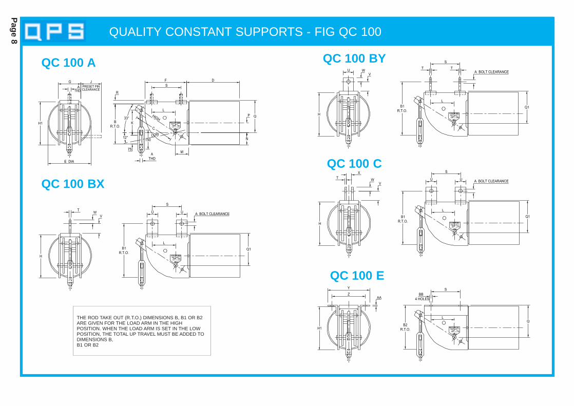
QUALITY CONSTANT SUPPORTS - FIG QC 100
Page 8
QC 100 A
QC 100 BX
QC 100 BY
QC 100 C
THE ROD TAKE OUT (R.T.O.) DIMENSIONS B, B1 OR B2ARE GIVEN FOR THE LOAD ARM IN THE HIGH POSITION. WHEN THE LOAD ARM IS SET IN THE LOWPOSITION, THE TOTAL UP TRAVEL MUST BE ADDED TODIMENSIONS B,B1 OR B2
QC 100 E

QUALITY CONSTANT SUPPORTS - FIG QC 100
Page 9
TRAVEL A B B1 B2 C Q Q1 H H140 12 311 386 326 54 130 130 180 18050 12 304 379 319 67 130 130 180 18060 12 296 371 311 80 130 130 180 18070 12 289 364 304 94 130 130 180 18080 12 282 357 297 107 130 130 180 18090 12 275 350 290 120 130 130 180 180100 12 267 342 282 134 130 130 180 180110 12 260 335 275 147 130 130 180 180120 12 253 328 268 160 130 130 180 180130 12 245 320 260 174 130 130 180 180140 12 238 313 253 187 130 130 180 180150 12 271 306 286 200 170 130 180 220160 12 263 298 278 214 170 130 180 220170 12 256 291 271 227 170 130 180 220180 12 249 284 264 240 170 130 180 220190 12 242 277 257 254 170 130 180 220200 12 235 270 250 267 170 130 180 220210 12 228 263 243 280 170 130 180 220220 12 250 255 265 294 200 130 180 250230 12 243 248 258 307 200 130 180 250240 12 236 241 251 320 200 130 180 250250 12 248 233 263 334 220 130 180 270260 12 241 226 256 347 220 130 180 270270 12 254 219 269 360 240 130 180 290280 12 246 211 261 374 240 130 180 290290 12 239 214 254 387 240 140 190 290300 12 232 207 247 400 240 140 190 290
SIZES 1 TO 6
TRAVEL A B B1 B2 C Q Q1 H H140 20 336 416 356 54 160 160 215 21550 16 329 409 349 67 160 160 215 21560 16 321 401 341 80 160 160 215 21570 16 314 394 334 94 160 160 215 21580 12 307 387 327 107 160 160 215 21590 12 300 380 320 120 160 160 215 215100 12 292 372 312 134 160 160 215 215110 12 285 365 305 147 160 160 215 215120 12 278 358 298 160 160 160 215 215130 12 270 350 290 174 160 160 215 215140 12 263 343 283 187 160 160 215 215150 12 256 336 276 200 160 160 215 215160 12 248 328 268 214 160 160 215 215170 12 241 321 261 227 160 160 215 215180 12 254 314 274 240 180 160 215 235190 12 247 307 267 254 180 160 215 235200 12 240 300 260 267 180 160 215 235210 12 233 293 253 280 180 160 215 235220 12 255 285 275 294 210 160 215 265230 12 248 278 268 307 210 160 215 265240 12 241 271 261 320 210 160 215 265250 12 253 263 273 334 230 160 215 285260 12 246 256 266 347 230 160 215 285270 12 259 249 279 360 250 160 215 305280 12 251 241 271 374 250 160 215 305290 12 244 234 264 387 250 160 215 305300 12 237 227 257 400 250 160 215 305310 12 270 250 290 414 290 190 245 345320 12 262 242 282 427 290 190 245 345330 12 255 235 275 440 290 190 245 345340 12 248 228 268 454 290 190 245 345350 12 242 222 262 464 290 190 245 345
SIZES 7 TO 12TRAVEL A B B1 B2 C Q Q1 H H1
60 20 371 451 396 80 215 205 270 27070 20 364 444 389 94 215 205 270 27080 20 357 437 382 107 215 205 270 27090 16 350 430 375 120 215 205 270 270
100 16 342 422 367 134 215 205 270 270110 16 335 415 360 147 215 205 270 270120 16 328 408 353 160 215 205 270 270130 16 320 400 345 174 215 205 270 270140 16 313 393 338 187 215 205 270 270150 16 306 386 331 200 215 205 270 270160 12 298 378 323 214 215 205 270 270170 12 291 371 316 227 215 205 270 270180 12 284 364 309 240 215 205 270 270190 12 277 357 302 254 215 205 270 270200 12 270 350 295 267 215 205 270 270210 12 263 343 288 280 215 205 270 270220 12 255 335 280 294 215 205 270 270230 12 248 328 273 307 215 205 270 270240 12 241 321 266 320 215 205 270 270250 12 233 313 258 334 215 205 270 270260 12 226 306 251 347 215 205 270 270270 12 254 299 279 360 250 205 270 300280 12 246 291 271 374 250 205 270 300290 12 239 284 264 387 250 205 270 300300 12 252 277 277 400 270 205 270 320310 12 245 270 270 414 270 205 270 320320 12 237 262 262 427 270 205 270 320330 12 250 255 275 440 290 205 270 340340 12 243 248 268 454 290 205 270 340350 12 237 242 262 464 290 205 270 340360 12 229 234 254 480 290 205 270 340370 12 266 251 291 494 335 230 290 385380 12 259 244 284 507 335 230 290 385390 12 252 237 277 520 335 230 290 385400 12 244 229 269 534 335 230 290 385410 12 237 222 262 547 335 230 290 385420 12 230 215 255 560 335 230 290 385
SIZES 13 TO 18TRAVEL A B B1 B2 C Q Q1 H H1
60 30 446 546 476 80 245 245 325 32570 30 439 539 469 94 245 245 325 32580 24 432 532 462 107 245 245 325 32590 24 425 525 455 120 245 245 325 325
100 24 417 517 447 134 245 245 325 325110 24 410 510 440 147 245 245 325 325120 20 403 503 433 160 245 245 325 325130 20 395 495 425 174 245 245 325 325140 20 388 488 418 187 245 245 325 325150 20 381 481 411 200 245 245 325 325160 20 373 473 403 214 245 245 325 325170 20 366 466 396 227 245 245 325 325180 16 359 459 389 240 245 245 325 325190 16 352 452 382 254 245 245 325 325200 16 345 445 375 267 245 245 325 325210 16 338 438 368 280 245 245 325 325220 16 330 430 360 294 245 245 325 325230 16 323 423 353 307 245 245 325 325240 16 316 416 346 320 245 245 325 325250 16 308 408 338 334 245 245 325 325260 16 301 401 331 347 245 245 325 325270 16 294 394 324 360 245 245 325 325280 16 336 386 366 374 295 245 325 375290 16 329 379 359 387 295 245 325 375300 16 322 372 352 400 295 245 325 375310 16 315 365 345 414 295 245 325 375320 16 307 357 337 427 295 245 325 375330 12 300 350 330 440 295 245 325 375340 12 293 343 323 454 295 245 325 375350 12 287 337 317 464 295 245 325 375360 12 279 329 309 480 295 245 325 375370 12 301 321 331 494 325 245 325 405380 12 294 314 324 507 325 245 325 405390 12 287 307 317 520 325 245 325 405400 12 304 299 334 534 350 245 325 430410 12 297 292 327 547 350 245 325 430420 12 290 285 320 560 350 245 325 430430 12 307 277 337 574 375 245 325 455440 12 300 270 330 587 375 245 325 455450 12 293 263 323 600 375 245 325 455460 12 286 256 316 614 375 245 325 455470 12 294 249 324 627 390 245 325 470480 12 286 241 316 641 390 245 325 470490 12 279 244 309 654 390 255 335 470500 12 272 237 302 667 390 255 335 470
SIZES 19 TO 26
SIZE 1-6 7-12 13-18 19-26 27-33 34-39 40-47 48-50 51-54 55-58 59-66D 250 300 350 400 600 750 1100 1265 1265 1265 1620E 150 220 295 330 390 440 525 525 525 525 640F 180 215 270 325 405 495 685 685 685 685 760G 115 120 135 150 180 225 280 345 345 345 455J 135 140 160 175 215 270 330 405 405 405 560K 150 150 150 200 200 200 250 300 300 300 300L 105 120 155 190 235 290 355 340 340 340 380M 55 65 75 95 115 145 198 250 250 250 280N 55 65 75 95 115 145 180 190 190 190 215P 33 38 55 66 83 100 TBLE 182 182 182 TBLER 15 20 25 30 35 40 50 60 70 80 80S 140 155 190 240 300 365 455 480 480 480 560T 10 12 12 20 25 30 40 40 40 40 40U 40 50 70 80 100 130 150 200 200 200 200V 60 60 65 70 75 75 90 140 140 140 150X 35 35 50 50 65 75 90 110 110 110 120Y 215 220 255 280 320 425 480 745 745 745 855Z 165 180 209 220 269 347 411 530 530 530 700
AA 6 6 8 8 10 10 15 20 20 20 25BB 14 18 22 22 22 27 33 45 45 45 51
FIG QC 100 SIZES 1-66
SIZE M12 M16 M20 M24 M30 M36 M42 M48 M56 M64 M72 M80 M90W 25 25 30 35 40 50 60 65 80 85 100 110 120
‘W’ DIMENSION FOR BOLT SIZE ‘A’
SIZE 40-44 45-47 59 60 61 62 63 64 65 66P 121 165 188 193 197 203 207 211 216 220
‘P’ DIMENSION
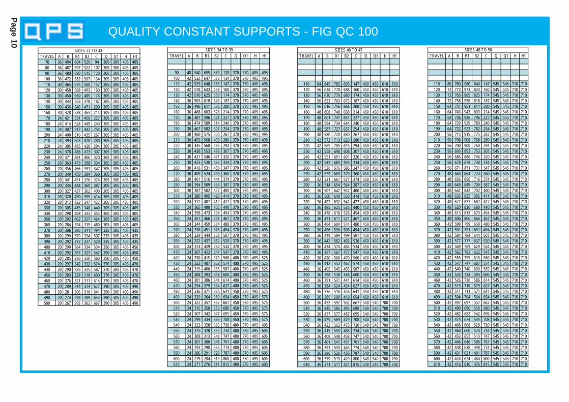
QUALITY CONSTANT SUPPORTS - FIG QC 100
Page 10
TRAVEL A B B1 B2 C Q Q1 H H1
90 48 540 655 580 120 370 370 495 495100 42 532 647 572 134 370 370 495 495110 42 525 640 565 147 370 370 495 495120 42 518 633 558 160 370 370 495 495130 42 510 625 550 174 370 370 495 495140 36 503 618 543 187 370 370 495 495150 36 496 611 536 200 370 370 495 495160 36 488 603 528 214 370 370 495 495170 36 481 596 521 227 370 370 495 495180 36 474 589 514 240 370 370 495 495190 30 467 582 507 254 370 370 495 495200 30 460 575 500 267 370 370 495 495210 30 453 568 493 280 370 370 495 495220 30 445 560 485 294 370 370 495 495230 30 438 553 478 307 370 370 495 495240 30 431 546 471 320 370 370 495 495250 30 423 538 463 334 370 370 495 495260 30 416 531 456 347 370 370 495 495270 30 409 524 449 360 370 370 495 495280 30 401 516 441 374 370 370 495 495290 30 394 509 434 387 370 370 495 495300 30 387 502 427 400 370 370 495 495310 24 380 495 420 414 370 370 495 495320 24 372 487 412 427 370 370 495 495330 24 365 480 405 440 370 370 495 495340 24 358 473 398 454 370 370 495 495350 24 351 466 391 467 370 370 495 495360 24 344 459 384 480 370 370 495 495370 24 336 451 376 494 370 370 495 495380 24 329 444 369 507 370 370 495 495390 24 322 437 362 520 370 370 495 495400 24 314 429 354 534 370 370 495 495410 24 307 422 347 547 370 370 495 495420 24 330 415 370 560 400 370 495 525430 24 322 407 362 574 400 370 495 525440 24 315 400 355 587 400 370 495 525450 24 308 393 348 600 400 370 495 525460 24 301 386 341 614 400 370 495 525470 24 294 379 334 627 400 370 495 525480 24 336 371 376 641 450 370 495 575490 24 329 364 369 654 450 370 495 575500 24 322 357 362 667 450 370 495 575510 24 315 350 355 680 450 370 495 575520 24 307 342 347 695 450 370 495 575530 24 299 334 339 708 450 370 495 575540 24 323 328 363 720 480 370 495 605550 24 315 320 355 734 480 370 495 605560 24 308 313 348 747 480 370 495 605570 24 301 306 341 761 480 370 495 605580 24 293 298 333 774 480 370 495 605590 24 286 291 326 787 480 370 495 605600 24 279 284 319 800 480 370 495 605610 24 271 276 311 815 480 370 495 605
SIZES 34 TO 39TRAVEL A B B1 B2 C Q Q1 H H1
110 64 645 785 695 147 450 450 610 610120 56 638 778 688 160 450 450 610 610130 56 630 770 680 174 450 450 610 610140 56 623 763 673 187 450 450 610 610150 56 616 756 666 200 450 450 610 610160 48 608 748 658 214 450 450 610 610170 48 601 741 651 227 450 450 610 610180 48 594 734 644 240 450 450 610 610190 48 587 727 637 254 450 450 610 610200 48 580 720 630 267 450 450 610 610210 42 573 713 623 280 450 450 610 610220 42 565 705 615 294 450 450 610 610230 42 558 698 608 307 450 450 610 610240 42 551 691 601 320 450 450 610 610250 42 543 683 593 334 450 450 610 610260 42 536 676 586 347 450 450 610 610270 42 529 669 579 360 450 450 610 610280 42 521 661 571 374 450 450 610 610290 36 514 654 564 387 450 450 610 610300 36 507 647 557 400 450 450 610 610310 36 500 640 550 414 450 450 610 610320 36 492 632 542 427 450 450 610 610330 36 485 625 535 440 450 450 610 610340 36 478 618 528 454 450 450 610 610350 36 471 611 521 467 450 450 610 610360 36 464 604 514 480 450 450 610 610370 36 456 596 506 494 450 450 610 610380 36 449 589 499 507 450 450 610 610390 36 442 582 492 520 450 450 610 610400 36 434 574 484 534 450 450 610 610410 36 427 567 477 547 450 450 610 610420 36 420 560 470 560 450 450 610 610430 36 412 552 462 574 450 450 610 610440 36 405 545 455 587 450 450 610 610450 36 398 538 448 600 450 450 610 610460 36 391 531 441 614 450 450 610 610470 36 384 524 434 627 450 450 610 610480 36 376 516 426 641 450 450 610 610490 36 369 509 419 654 450 450 610 610500 36 452 592 502 667 540 540 700 700510 36 445 585 495 680 540 540 700 700520 36 437 577 487 695 540 540 700 700530 36 429 569 479 708 540 540 700 700540 36 423 563 473 720 540 540 700 700550 36 415 555 465 734 540 540 700 700560 36 408 548 458 747 540 540 700 700570 36 401 541 451 761 540 540 700 700580 36 393 533 443 774 540 540 700 700590 36 386 526 436 787 540 540 700 700600 36 379 519 429 800 540 540 700 700610 36 371 511 421 815 540 540 700 700
SIZES 40 TO 47TRAVEL A B B1 B2 C Q Q1 H H1
110 80 780 980 840 147 545 545 710 710120 72 773 973 833 160 545 545 710 710130 72 765 965 825 174 545 545 710 710140 72 758 958 818 187 545 545 710 710150 64 751 951 811 200 545 545 710 710160 64 743 943 803 214 545 545 710 710170 64 736 936 796 227 545 545 710 710180 64 729 929 789 240 545 545 710 710190 64 722 922 782 254 545 545 710 710200 56 715 915 775 267 545 545 710 710210 56 708 908 768 280 545 545 710 710220 56 700 900 760 294 545 545 710 710230 56 693 893 753 307 545 545 710 710240 56 686 886 746 320 545 545 710 710250 56 678 878 738 334 545 545 710 710260 56 671 871 731 347 545 545 710 710270 48 664 864 724 360 545 545 710 710280 48 656 856 716 374 545 545 710 710290 48 649 849 709 387 545 545 710 710300 48 642 842 702 400 545 545 710 710310 48 635 835 695 414 545 545 710 710320 48 627 827 687 427 545 545 710 710330 48 620 820 680 440 545 545 710 710340 48 613 813 673 454 545 545 710 710350 48 606 806 666 467 545 545 710 710360 42 599 799 659 480 545 545 710 710370 42 591 791 651 494 545 545 710 710380 42 584 784 644 507 545 545 710 710390 42 577 777 637 520 545 545 710 710400 42 569 769 629 534 545 545 710 710410 42 562 762 622 547 545 545 710 710420 42 555 755 615 560 545 545 710 710430 42 547 747 607 574 545 545 710 710440 42 540 740 600 587 545 545 710 710450 42 533 733 593 600 545 545 710 710460 42 526 726 586 614 545 545 710 710470 42 519 719 579 627 545 545 710 710480 42 511 711 571 641 545 545 710 710490 42 504 704 564 654 545 545 710 710500 42 497 697 557 667 545 545 710 710510 42 490 690 550 680 545 545 710 710520 42 482 682 542 695 545 545 710 710530 42 474 674 534 708 545 545 710 710540 42 468 668 528 720 545 545 710 710550 42 460 660 520 734 545 545 710 710560 42 453 653 513 747 545 545 710 710570 42 446 646 506 761 545 545 710 710580 42 438 638 498 774 545 545 710 710590 42 431 631 491 787 545 545 710 710600 42 424 624 484 800 545 545 710 710610 42 416 616 476 815 545 545 710 710
SIZES 48 TO 50
TRAVEL A B B1 B2 C Q Q1 H H170 36 494 604 529 94 305 305 405 40580 36 487 597 522 107 305 305 405 40590 36 480 590 515 120 305 305 405 405
100 36 472 582 507 134 305 305 405 405110 30 465 575 500 147 305 305 405 405120 30 458 568 493 160 305 305 405 405130 30 450 560 485 174 305 305 405 405140 30 443 553 478 187 305 305 405 405150 30 436 546 471 200 305 305 405 405160 30 428 538 463 214 305 305 405 405170 24 421 531 456 227 305 305 405 405180 24 414 524 449 240 305 305 405 405190 24 407 517 442 254 305 305 405 405200 24 400 510 435 267 305 305 405 405210 24 393 503 428 280 305 305 405 405220 24 385 495 420 294 305 305 405 405230 24 378 488 413 307 305 305 405 405240 20 371 481 406 320 305 305 405 405250 20 363 473 398 334 305 305 405 405260 20 356 466 391 347 305 305 405 405270 20 349 459 384 360 305 305 405 405280 20 341 451 376 374 305 305 405 405290 20 334 444 369 387 305 305 405 405300 20 327 437 362 400 305 305 405 405310 20 320 430 355 414 305 305 405 405320 20 312 422 347 427 305 305 405 405330 20 305 415 340 440 305 305 405 405340 20 298 408 333 454 305 305 405 405350 20 292 402 327 464 305 305 405 405360 20 284 394 319 480 305 305 405 405370 20 306 386 341 494 335 305 405 435380 20 299 379 334 507 335 305 405 435390 20 292 372 327 520 335 305 405 435400 20 299 364 334 534 350 305 405 450410 20 292 357 327 547 350 305 405 450420 20 285 350 320 560 350 305 405 450430 20 297 342 332 574 370 305 405 470440 20 290 335 325 587 370 305 405 470450 20 283 328 318 600 370 305 405 470460 20 276 321 311 614 370 305 405 470470 20 289 314 324 627 390 305 405 490480 20 281 306 316 641 390 305 405 490490 20 274 299 309 654 390 305 405 490500 20 267 292 302 667 390 305 405 490
SIZES 27 TO 33
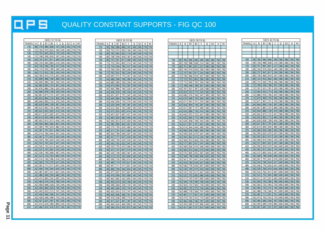
QUALITY CONSTANT SUPPORTS - FIG QC 100
Page 11
TRAVEL A B B1 B2 C Q Q1 H H1110 80 770 980 840 147 545 545 710 710120 72 763 973 833 160 545 545 710 710130 72 755 965 825 174 545 545 710 710140 72 748 958 818 187 545 545 710 710150 64 741 951 811 200 545 545 710 710160 64 733 943 803 214 545 545 710 710170 64 726 936 796 227 545 545 710 710180 64 719 929 789 240 545 545 710 710190 64 712 922 782 254 545 545 710 710200 56 705 915 775 267 545 545 710 710210 56 698 908 768 280 545 545 710 710220 56 690 900 760 294 545 545 710 710230 56 683 893 753 307 545 545 710 710240 56 676 886 746 320 545 545 710 710250 56 668 878 738 334 545 545 710 710260 56 661 871 731 347 545 545 710 710270 48 654 864 724 360 545 545 710 710280 48 646 856 716 374 545 545 710 710290 48 639 849 709 387 545 545 710 710300 48 632 842 702 400 545 545 710 710310 48 625 835 695 414 545 545 710 710320 48 617 827 687 427 545 545 710 710330 48 610 820 680 440 545 545 710 710340 48 603 813 673 454 545 545 710 710350 48 596 806 666 467 545 545 710 710360 42 589 799 659 480 545 545 710 710370 42 581 791 651 494 545 545 710 710380 42 574 784 644 507 545 545 710 710390 42 567 777 637 520 545 545 710 710400 42 559 769 629 534 545 545 710 710410 42 552 762 622 547 545 545 710 710420 42 545 755 615 560 545 545 710 710430 42 537 747 607 574 545 545 710 710440 42 530 740 600 587 545 545 710 710450 42 523 733 593 600 545 545 710 710460 42 516 726 586 614 545 545 710 710470 42 509 719 579 627 545 545 710 710480 42 501 711 571 641 545 545 710 710490 42 494 704 564 654 545 545 710 710500 42 487 697 557 667 545 545 710 710510 42 480 690 550 680 545 545 710 710520 42 472 682 542 695 545 545 710 710530 42 464 674 534 708 545 545 710 710540 42 458 668 528 720 545 545 710 710550 42 450 660 520 734 545 545 710 710560 42 443 653 513 747 545 545 710 710570 42 436 646 506 761 545 545 710 710580 42 428 638 498 774 545 545 710 710590 42 421 631 491 787 545 545 710 710600 42 414 624 484 800 545 545 710 710610 42 406 616 476 815 545 545 710 710
SIZES 51 TO 54
TRAVEL A B B1 B2 C Q Q1 H H1110 90 760 980 840 147 545 545 710 710120 90 753 973 833 160 545 545 710 710130 80 745 965 825 174 545 545 710 710140 80 738 958 818 187 545 545 710 710150 80 731 951 811 200 545 545 710 710160 72 723 943 803 214 545 545 710 710170 72 716 936 796 227 545 545 710 710180 72 709 929 789 240 545 545 710 710190 72 702 922 782 254 545 545 710 710200 64 695 915 775 267 545 545 710 710210 64 688 908 768 280 545 545 710 710220 64 680 900 760 294 545 545 710 710230 64 673 893 753 307 545 545 710 710240 64 666 886 746 320 545 545 710 710250 64 658 878 738 334 545 545 710 710260 56 651 871 731 347 545 545 710 710270 56 644 864 724 360 545 545 710 710280 56 636 856 716 374 545 545 710 710290 56 629 849 709 387 545 545 710 710300 56 622 842 702 400 545 545 710 710310 56 615 835 695 414 545 545 710 710320 56 607 827 687 427 545 545 710 710330 56 600 820 680 440 545 545 710 710340 56 593 813 673 454 545 545 710 710350 56 586 806 666 467 545 545 710 710360 48 579 799 659 480 545 545 710 710370 48 571 791 651 494 545 545 710 710380 48 564 784 644 507 545 545 710 710390 48 557 777 637 520 545 545 710 710400 48 549 769 629 534 545 545 710 710410 48 542 762 622 547 545 545 710 710420 48 535 755 615 560 545 545 710 710430 48 527 747 607 574 545 545 710 710440 48 520 740 600 587 545 545 710 710450 48 513 733 593 600 545 545 710 710460 48 506 726 586 614 545 545 710 710470 48 499 719 579 627 545 545 710 710480 48 491 711 571 641 545 545 710 710490 48 484 704 564 654 545 545 710 710500 48 477 697 557 667 545 545 710 710510 48 470 690 550 680 545 545 710 710520 48 462 682 542 695 545 545 710 710530 48 454 674 534 708 545 545 710 710540 48 448 668 528 720 545 545 710 710550 48 440 660 520 734 545 545 710 710560 48 433 653 513 747 545 545 710 710570 48 426 646 506 761 545 545 710 710580 48 418 638 498 774 545 545 710 710590 48 411 631 491 787 545 545 710 710600 48 404 624 484 800 545 545 710 710610 48 396 616 476 815 545 545 710 710
SIZES 55 TO 58TRAVEL A B B1 B2 C Q Q1 H H1
150 80 766 996 846 200 580 580 760 760160 80 758 988 838 214 580 580 760 760170 80 751 981 831 227 580 580 760 760180 80 744 974 824 240 580 580 760 760190 72 737 967 817 254 580 580 760 760200 72 730 960 810 267 580 580 760 760210 72 723 953 803 280 580 580 760 760220 72 715 945 795 294 580 580 760 760230 72 708 938 788 307 580 580 760 760240 64 701 931 781 320 580 580 760 760250 64 693 923 773 334 580 580 760 760260 64 686 916 766 347 580 580 760 760270 64 679 909 759 360 580 580 760 760280 64 671 901 751 374 580 580 760 760290 64 664 894 744 387 580 580 760 760300 64 657 887 737 400 580 580 760 760310 64 650 880 730 414 580 580 760 760320 56 642 872 722 427 580 580 760 760330 56 635 865 715 440 580 580 760 760340 56 628 858 708 454 580 580 760 760350 56 621 851 701 467 580 580 760 760360 56 614 844 694 480 580 580 760 760370 56 606 836 686 494 580 580 760 760380 56 599 829 679 507 580 580 760 760390 56 592 822 672 520 580 580 760 760400 56 584 814 664 534 580 580 760 760410 56 577 807 657 547 580 580 760 760420 56 590 820 670 560 600 600 760 760430 56 582 812 662 574 600 600 760 760440 56 575 805 655 587 600 600 760 760450 56 568 798 648 600 600 600 760 760460 56 561 791 641 614 600 600 760 760470 56 554 784 634 627 600 600 760 760480 56 546 776 626 641 600 600 760 760490 56 539 769 619 654 600 600 760 760500 56 532 762 612 667 600 600 760 760510 56 525 755 605 680 600 600 760 760520 56 517 747 597 695 600 600 760 760530 56 509 739 589 708 600 600 760 760540 56 503 733 583 720 600 600 760 760550 56 495 725 575 734 600 600 760 760560 56 488 718 568 747 600 600 760 760570 56 481 711 561 761 600 600 760 760580 56 473 703 553 774 600 600 760 760590 56 466 696 546 787 600 600 760 760600 56 459 689 539 800 600 600 760 760610 56 451 681 531 815 600 600 760 760
SIZES 59 TO 62TRAVEL A B B1 B2 C Q Q1 H H1
150 90 766 996 846 200 580 580 760 760160 90 758 988 838 214 580 580 760 760170 90 751 981 831 227 580 580 760 760180 80 744 974 824 240 580 580 760 760190 80 737 967 817 254 580 580 760 760200 80 730 960 810 267 580 580 760 760210 80 723 953 803 280 580 580 760 760220 80 715 945 795 294 580 580 760 760230 72 708 938 788 307 580 580 760 760240 72 701 931 781 320 580 580 760 760250 72 693 923 773 334 580 580 760 760260 72 686 916 766 347 580 580 760 760270 72 679 909 759 360 580 580 760 760280 72 671 901 751 374 580 580 760 760290 64 664 894 744 387 580 580 760 760300 64 657 887 737 400 580 580 760 760310 64 650 880 730 414 580 580 760 760320 64 642 872 722 427 580 580 760 760330 64 635 865 715 440 580 580 760 760340 64 628 858 708 454 580 580 760 760350 64 621 851 701 467 580 580 760 760360 64 614 844 694 480 580 580 760 760370 64 606 836 686 494 580 580 760 760380 56 599 829 679 507 580 580 760 760390 56 592 822 672 520 580 580 760 760400 56 584 814 664 534 580 580 760 760410 56 577 807 657 547 580 580 760 760420 56 590 820 670 560 600 600 760 760430 56 582 812 662 574 600 600 760 760440 56 575 805 655 587 600 600 760 760450 56 568 798 648 600 600 600 760 760460 56 561 791 641 614 600 600 760 760470 56 554 784 634 627 600 600 760 760480 56 546 776 626 641 600 600 760 760490 56 539 769 619 654 600 600 760 760500 56 532 762 612 667 600 600 760 760510 56 525 755 605 680 600 600 760 760520 56 517 747 597 695 600 600 760 760530 56 509 739 589 708 600 600 760 760540 56 503 733 583 720 600 600 760 760550 56 495 725 575 734 600 600 760 760560 56 488 718 568 747 600 600 760 760570 56 481 711 561 761 600 600 760 760580 56 473 703 553 774 600 600 760 760590 56 466 696 546 787 600 600 760 760600 56 459 689 539 800 600 600 760 760610 56 451 681 531 815 600 600 760 760
SIZES 63 TO 66

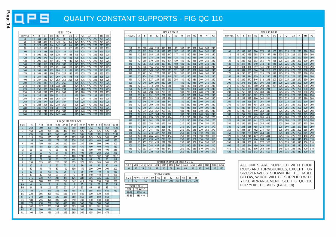
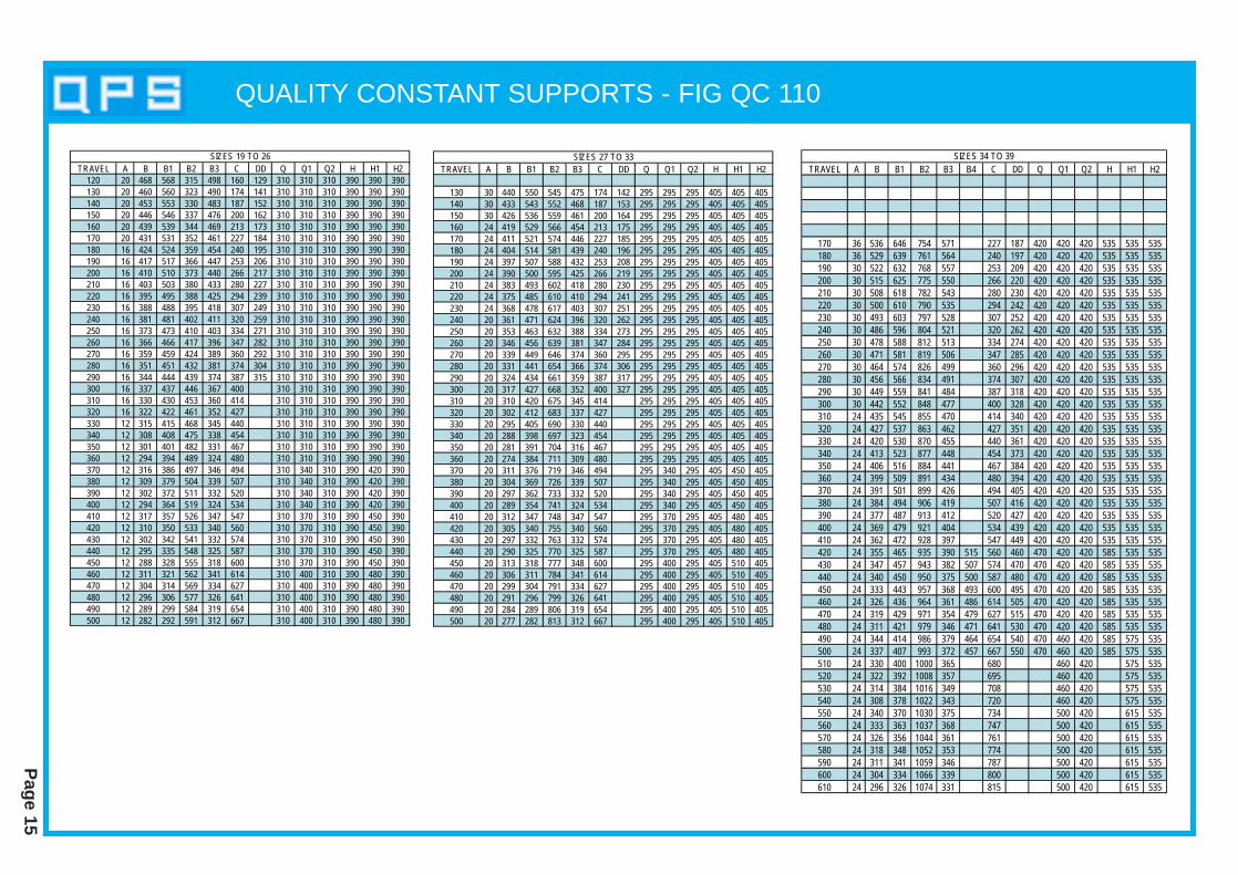
QUALITY CONSTANT SUPPORTS - FIG QC 110
Page 12
QC 110 B
QC 110 BX
QC 110 BY
QC 110 A
THE ROD TAKE OUT(R.T.O.) DIMENSIONS B,B1 OR B3 ARE GIVENFOR THE LOAD ARM INTHE HIGH POSITION.WHEN THE LOAD ARM ISSET IN THE LOW POSITION, THE TOTALUP TRAVEL MUST BEADDED TO DIMENSIONSB, B1 OR B3
QUALITY CONSTANT SUPPORTS - FIG QC 110
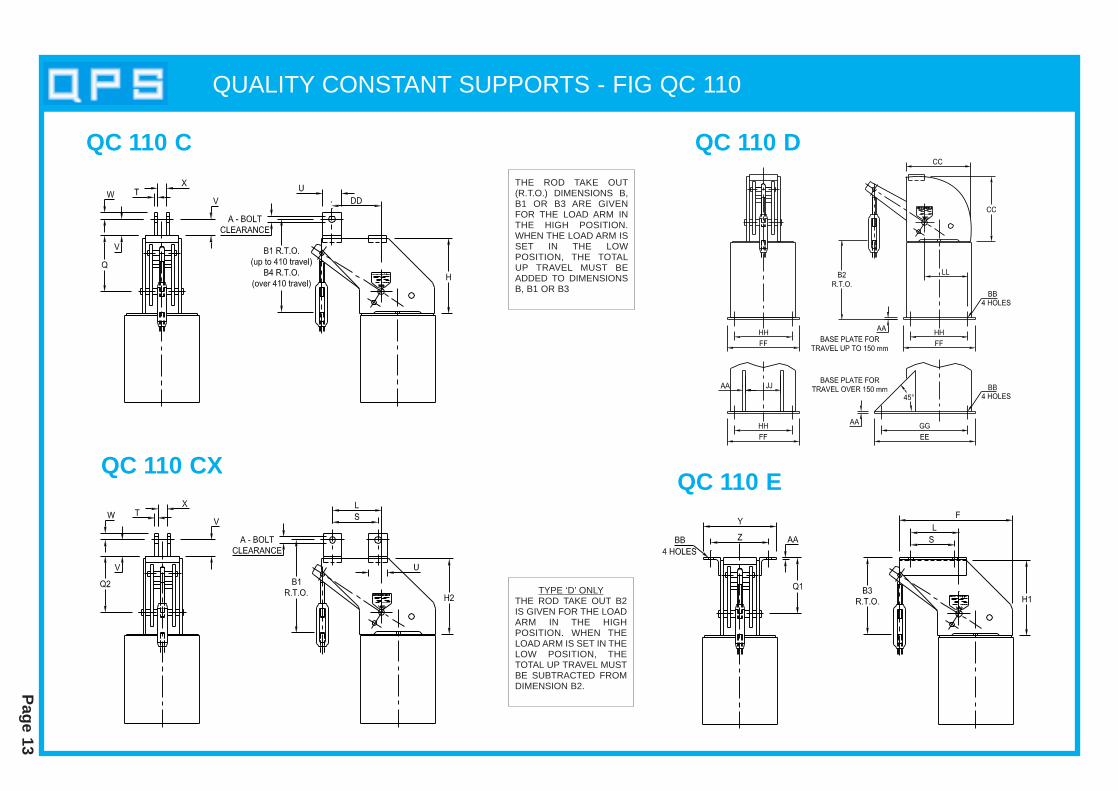
Page 13
QC 110 C QC 110 D
QC 110 EQC 110 CX
THE ROD TAKE OUT(R.T.O.) DIMENSIONS B,B1 OR B3 ARE GIVENFOR THE LOAD ARM INTHE HIGH POSITION.WHEN THE LOAD ARM ISSET IN THE LOW POSITION, THE TOTALUP TRAVEL MUST BEADDED TO DIMENSIONSB, B1 OR B3
TYPE ‘D’ ONLYTHE ROD TAKE OUT B2IS GIVEN FOR THE LOADARM IN THE HIGH POSITION. WHEN THELOAD ARM IS SET IN THELOW POSITION, THETOTAL UP TRAVEL MUSTBE SUBTRACTED FROMDIMENSION B2.
QUALITY CONSTANT SUPPORTS - FIG QC 110
Page 14
TRAVEL A B B1 B2 B3 C DD Q Q1 Q2 H H1 H260 12 341 416 130 356 80 64 175 175 175 225 225 22570 12 334 409 137 349 94 64 175 175 175 225 225 22580 12 327 402 144 342 107 86 175 175 175 225 225 22590 12 320 395 151 335 120 97 175 175 175 225 225 225
100 12 313 388 158 328 133 107 175 175 175 225 225 225110 12 305 380 166 320 147 118 175 175 175 225 225 225120 12 298 373 173 313 160 128 175 175 175 225 225 225130 12 290 365 181 305 174 140 175 175 175 225 225 225140 12 283 358 188 298 187 150 175 175 175 225 225 225150 12 276 351 195 291 200 161 175 175 175 225 225 225160 12 269 344 202 284 213 172 175 175 175 225 225 225170 12 261 336 210 276 227 182 175 175 175 225 225 225180 12 254 329 217 269 240 193 175 175 175 225 225 225190 12 247 322 224 262 253 203 175 175 175 225 225 225200 12 240 315 231 255 266 175 175 175 225 225 225210 12 233 308 238 248 280 175 175 175 225 225 225220 12 250 300 246 265 294 175 200 175 225 250 225230 12 243 293 253 258 307 175 200 175 225 250 225240 12 236 286 260 251 320 175 200 175 225 250 225250 12 248 278 268 263 334 175 220 175 225 270 225260 12 241 271 275 256 347 175 220 175 225 270 225270 12 234 264 282 249 360 175 220 175 225 270 225280 12 246 256 290 261 374 175 240 175 225 290 225290 12 239 249 297 254 387 175 240 175 225 290 225300 12 232 242 304 247 400 175 240 175 225 290 225
SIZES 1 TO 6 TRAVEL A B B1 B2 B3 C DD Q Q1 Q2 H H1 H2
90 12 320 400 211 340 120 96 180 180 180 240 240 240100 12 313 393 218 333 133 107 180 180 180 240 240 240110 12 305 385 226 325 147 117 180 180 180 240 240 240120 12 298 378 233 318 160 128 180 180 180 240 240 240130 12 290 370 241 310 174 139 180 180 180 240 240 240140 12 283 363 248 303 187 150 180 180 180 240 240 240150 12 276 356 255 296 200 160 180 180 180 240 240 240160 12 269 349 262 289 213 171 180 180 180 240 240 240170 12 261 341 270 281 227 181 180 180 180 240 240 240180 12 254 334 277 274 240 192 180 180 180 240 240 240190 12 247 327 284 267 253 204 180 180 180 240 240 240200 12 240 320 291 260 266 180 180 180 240 240 240210 12 233 313 298 253 280 180 180 180 240 240 240220 12 255 305 306 275 294 180 210 180 240 270 240230 12 248 298 313 268 307 180 210 180 240 270 240240 12 241 291 320 261 320 180 210 180 240 270 240250 12 253 283 328 273 334 180 230 180 240 290 240260 12 246 276 335 266 347 180 230 180 240 290 240270 12 239 269 342 259 360 180 230 180 240 290 240280 12 246 261 350 266 374 180 245 180 240 305 240290 12 239 254 357 259 387 180 245 180 240 305 240300 12 232 247 364 252 400 180 245 180 240 305 240310 12 270 270 371 290 414 210 290 210 270 350 270320 12 262 262 379 282 427 210 290 210 270 350 270330 12 255 255 386 275 440 210 290 210 270 350 270340 12 248 248 393 268 454 210 290 210 270 350 270350 12 241 241 400 261 467 210 290 210 270 350 270360 12 274 274 407 294 480 250 330 250 310 390 310370 12 266 266 415 286 494 250 330 250 310 390 310380 12 259 259 422 279 507 250 330 250 310 390 310390 12 252 252 429 272 520 250 330 250 310 390 310400 12 244 244 437 264 534 250 330 250 310 390 310410 12 237 237 444 257 547 250 330 250 310 390 310420 12 230 230 451 250 560 250 330 250 310 390 310
SIZES 7 TO 12TRAVEL A B B1 B2 B3 C DD Q Q1 Q2 H H1 H2
100 16 348 443 280 378 133 105 225 225 225 290 290 290110 16 340 435 288 370 147 116 225 225 225 290 290 290120 16 333 428 295 363 160 126 225 225 225 290 290 290130 16 325 420 303 355 174 138 225 225 225 290 290 290140 16 318 413 310 348 187 148 225 225 225 290 290 290150 16 311 406 317 341 200 158 225 225 225 290 290 290160 12 304 399 324 334 213 169 225 225 225 290 290 290170 12 296 391 332 326 227 179 225 225 225 290 290 290180 12 289 384 339 319 240 189 225 225 225 290 290 290190 12 282 377 346 312 253 200 225 225 225 290 290 290200 12 275 370 353 305 266 211 225 225 225 290 290 290210 12 268 363 360 298 280 221 225 225 225 290 290 290220 12 260 355 368 290 294 225 225 225 290 290 290230 12 253 348 375 283 307 225 225 225 290 290 290240 12 246 341 382 276 320 225 225 225 290 290 290250 12 238 333 390 268 334 225 225 225 290 290 290260 12 231 326 397 261 347 225 225 225 290 290 290270 12 254 319 404 284 360 225 255 225 290 320 290280 12 246 311 412 276 374 225 255 225 290 320 290290 12 239 304 419 269 387 225 255 225 290 320 290300 12 257 297 426 287 400 225 280 225 290 345 290310 12 250 290 433 280 414 225 280 225 290 345 290320 12 242 282 441 272 427 225 280 225 290 345 290330 12 255 275 448 285 440 225 300 225 290 365 290340 12 248 268 455 278 454 225 300 225 290 365 290350 12 241 261 462 271 467 225 300 225 290 365 290360 12 234 254 469 264 480 225 300 225 290 365 290370 12 261 246 477 291 494 225 335 225 290 400 290380 12 254 259 484 284 507 245 335 245 310 400 310390 12 247 252 491 277 520 245 335 245 310 400 310400 12 239 244 499 269 534 245 335 245 310 400 310410 12 232 237 506 262 547 245 335 245 310 400 310420 12 225 230 513 255 560 245 335 245 310 400 310
SIZES 13 TO 18
SIZE 1-6 7-12 13-18 19-26 27-33 34-39 40-47 48-50 51-54 55-58 59-66D 250 300 350 400 600 750 1100 1265 1265 1265 1620E 150 220 295 330 390 440 525 525 525 525 640F 295 330 455 550 615 815 945 1080 1080 1080 1100G 115 120 135 150 180 225 280 345 345 345 455J 135 140 160 175 215 270 330 405 405 405 560K 150 150 150 200 200 200 250 300 300 300 300L 150 155 225 260 285 400 430 460 460 460 430M 55 65 75 95 115 145 180 190 190 190 215N 55 65 75 95 115 145 198 250 250 250 280P 33 38 65 66 83 100 TBLE 182 182 182 TBLER 15 20 30 30 35 40 50 60 70 80 80S 130 125 195 220 240 355 370 365 365 365 500T 10 12 12 20 25 25 30 40 40 40 40U 40 50 70 80 100 130 150 200 200 200 200V 60 60 65 70 75 75 90 140 140 140 150X 35 35 50 50 65 75 90 110 110 110 120Y 215 220 255 280 320 425 480 745 745 745 855Z 165 180 209 220 269 347 411 530 530 530 700
AA 6 6 8 8 10 10 15 20 20 20 25BB 14 18 22 22 22 27 33 45 45 45 51CC 180 215 270 325 405 495 610 685 685 685 760EE 220 305 420 460 585 610 840 930 930 930FF 210 280 330 420 485 560 660 660 660 660GG 180 255 370 395 510 510 740 830 830 830HH 170 230 280 355 410 460 560 560 560 560JJ 102 127 203 254 305 305 381 381 381 381KK 80 100 170 180 230 240 360 360 360 360LL 100 130 190 215 255 285 360 455 504 475
FIG QC 110 SIZES 1-66
SIZE M12 M16 M20 M24 M30 M36 M42 M48 M56 M64 M72 M80 M90W 25 25 30 35 40 50 60 65 80 85 100 110 120
‘W’ DIMENSION FOR BOLT SIZE ‘A’
SIZE 40-44 45-47 59 60 61 62 63 64 65 66P 121 165 188 193 197 203 207 211 216 220
‘P’ DIMENSION
SIZE TRAVELS48-58 170-41059-66 180-410
YOKE TABLE
ALL UNITS ARE SUPPLIED WITH DROPRODS AND TURNBUCKLES, EXCEPT FORSIZES/TRAVELS SHOWN IN THE TABLEBELOW, WHICH WILL BE SUPPLIED WITHYOKE ARRANGEMENT. SEE FIG QC 120FOR YOKE DETAILS. (PAGE 18)
QUALITY CONSTANT SUPPORTS - FIG QC 110
Page 15
TRAVEL A B B1 B2 B3 C DD Q Q1 Q2 H H1 H2120 20 468 568 315 498 160 129 310 310 310 390 390 390130 20 460 560 323 490 174 141 310 310 310 390 390 390140 20 453 553 330 483 187 152 310 310 310 390 390 390150 20 446 546 337 476 200 162 310 310 310 390 390 390160 20 439 539 344 469 213 173 310 310 310 390 390 390170 20 431 531 352 461 227 184 310 310 310 390 390 390180 16 424 524 359 454 240 195 310 310 310 390 390 390190 16 417 517 366 447 253 206 310 310 310 390 390 390200 16 410 510 373 440 266 217 310 310 310 390 390 390210 16 403 503 380 433 280 227 310 310 310 390 390 390220 16 395 495 388 425 294 239 310 310 310 390 390 390230 16 388 488 395 418 307 249 310 310 310 390 390 390240 16 381 481 402 411 320 259 310 310 310 390 390 390250 16 373 473 410 403 334 271 310 310 310 390 390 390260 16 366 466 417 396 347 282 310 310 310 390 390 390270 16 359 459 424 389 360 292 310 310 310 390 390 390280 16 351 451 432 381 374 304 310 310 310 390 390 390290 16 344 444 439 374 387 315 310 310 310 390 390 390300 16 337 437 446 367 400 310 310 310 390 390 390310 16 330 430 453 360 414 310 310 310 390 390 390320 16 322 422 461 352 427 310 310 310 390 390 390330 12 315 415 468 345 440 310 310 310 390 390 390340 12 308 408 475 338 454 310 310 310 390 390 390350 12 301 401 482 331 467 310 310 310 390 390 390360 12 294 394 489 324 480 310 310 310 390 390 390370 12 316 386 497 346 494 310 340 310 390 420 390380 12 309 379 504 339 507 310 340 310 390 420 390390 12 302 372 511 332 520 310 340 310 390 420 390400 12 294 364 519 324 534 310 340 310 390 420 390410 12 317 357 526 347 547 310 370 310 390 450 390420 12 310 350 533 340 560 310 370 310 390 450 390430 12 302 342 541 332 574 310 370 310 390 450 390440 12 295 335 548 325 587 310 370 310 390 450 390450 12 288 328 555 318 600 310 370 310 390 450 390460 12 311 321 562 341 614 310 400 310 390 480 390470 12 304 314 569 334 627 310 400 310 390 480 390480 12 296 306 577 326 641 310 400 310 390 480 390490 12 289 299 584 319 654 310 400 310 390 480 390500 12 282 292 591 312 667 310 400 310 390 480 390
SIZES 19 TO 26TRAVEL A B B1 B2 B3 C DD Q Q1 Q2 H H1 H2
130 30 440 550 545 475 174 142 295 295 295 405 405 405140 30 433 543 552 468 187 153 295 295 295 405 405 405150 30 426 536 559 461 200 164 295 295 295 405 405 405160 24 419 529 566 454 213 175 295 295 295 405 405 405170 24 411 521 574 446 227 185 295 295 295 405 405 405180 24 404 514 581 439 240 196 295 295 295 405 405 405190 24 397 507 588 432 253 208 295 295 295 405 405 405200 24 390 500 595 425 266 219 295 295 295 405 405 405210 24 383 493 602 418 280 230 295 295 295 405 405 405220 24 375 485 610 410 294 241 295 295 295 405 405 405230 24 368 478 617 403 307 251 295 295 295 405 405 405240 20 361 471 624 396 320 262 295 295 295 405 405 405250 20 353 463 632 388 334 273 295 295 295 405 405 405260 20 346 456 639 381 347 284 295 295 295 405 405 405270 20 339 449 646 374 360 295 295 295 295 405 405 405280 20 331 441 654 366 374 306 295 295 295 405 405 405290 20 324 434 661 359 387 317 295 295 295 405 405 405300 20 317 427 668 352 400 327 295 295 295 405 405 405310 20 310 420 675 345 414 295 295 295 405 405 405320 20 302 412 683 337 427 295 295 295 405 405 405330 20 295 405 690 330 440 295 295 295 405 405 405340 20 288 398 697 323 454 295 295 295 405 405 405350 20 281 391 704 316 467 295 295 295 405 405 405360 20 274 384 711 309 480 295 295 295 405 405 405370 20 311 376 719 346 494 295 340 295 405 450 405380 20 304 369 726 339 507 295 340 295 405 450 405390 20 297 362 733 332 520 295 340 295 405 450 405400 20 289 354 741 324 534 295 340 295 405 450 405410 20 312 347 748 347 547 295 370 295 405 480 405420 20 305 340 755 340 560 295 370 295 405 480 405430 20 297 332 763 332 574 295 370 295 405 480 405440 20 290 325 770 325 587 295 370 295 405 480 405450 20 313 318 777 348 600 295 400 295 405 510 405460 20 306 311 784 341 614 295 400 295 405 510 405470 20 299 304 791 334 627 295 400 295 405 510 405480 20 291 296 799 326 641 295 400 295 405 510 405490 20 284 289 806 319 654 295 400 295 405 510 405500 20 277 282 813 312 667 295 400 295 405 510 405
SIZES 27 TO 33TRAVEL A B B1 B2 B3 B4 C DD Q Q1 Q2 H H1 H2
170 36 536 646 754 571 227 187 420 420 420 535 535 535180 36 529 639 761 564 240 197 420 420 420 535 535 535190 30 522 632 768 557 253 209 420 420 420 535 535 535200 30 515 625 775 550 266 220 420 420 420 535 535 535210 30 508 618 782 543 280 230 420 420 420 535 535 535220 30 500 610 790 535 294 242 420 420 420 535 535 535230 30 493 603 797 528 307 252 420 420 420 535 535 535240 30 486 596 804 521 320 262 420 420 420 535 535 535250 30 478 588 812 513 334 274 420 420 420 535 535 535260 30 471 581 819 506 347 285 420 420 420 535 535 535270 30 464 574 826 499 360 296 420 420 420 535 535 535280 30 456 566 834 491 374 307 420 420 420 535 535 535290 30 449 559 841 484 387 318 420 420 420 535 535 535300 30 442 552 848 477 400 328 420 420 420 535 535 535310 24 435 545 855 470 414 340 420 420 420 535 535 535320 24 427 537 863 462 427 351 420 420 420 535 535 535330 24 420 530 870 455 440 361 420 420 420 535 535 535340 24 413 523 877 448 454 373 420 420 420 535 535 535350 24 406 516 884 441 467 384 420 420 420 535 535 535360 24 399 509 891 434 480 394 420 420 420 535 535 535370 24 391 501 899 426 494 405 420 420 420 535 535 535380 24 384 494 906 419 507 416 420 420 420 535 535 535390 24 377 487 913 412 520 427 420 420 420 535 535 535400 24 369 479 921 404 534 439 420 420 420 535 535 535410 24 362 472 928 397 547 449 420 420 420 535 535 535420 24 355 465 935 390 515 560 460 470 420 420 585 535 535430 24 347 457 943 382 507 574 470 470 420 420 585 535 535440 24 340 450 950 375 500 587 480 470 420 420 585 535 535450 24 333 443 957 368 493 600 495 470 420 420 585 535 535460 24 326 436 964 361 486 614 505 470 420 420 585 535 535470 24 319 429 971 354 479 627 515 470 420 420 585 535 535480 24 311 421 979 346 471 641 530 470 420 420 585 535 535490 24 344 414 986 379 464 654 540 470 460 420 585 575 535500 24 337 407 993 372 457 667 550 470 460 420 585 575 535510 24 330 400 1000 365 680 460 420 575 535520 24 322 392 1008 357 695 460 420 575 535530 24 314 384 1016 349 708 460 420 575 535540 24 308 378 1022 343 720 460 420 575 535550 24 340 370 1030 375 734 500 420 615 535560 24 333 363 1037 368 747 500 420 615 535570 24 326 356 1044 361 761 500 420 615 535580 24 318 348 1052 353 774 500 420 615 535590 24 311 341 1059 346 787 500 420 615 535600 24 304 334 1066 339 800 500 420 615 535610 24 296 326 1074 331 815 500 420 615 535
SIZES 34 TO 39
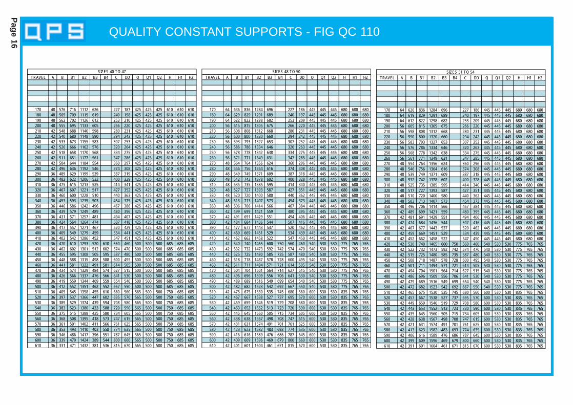
QUALITY CONSTANT SUPPORTS - FIG QC 110
Page 16
TRAVEL A B B1 B2 B3 B4 C DD Q Q1 Q2 H H1 H2
170 48 576 716 1112 626 227 187 425 425 425 610 610 610180 48 569 709 1119 619 240 198 425 425 425 610 610 610190 48 562 702 1126 612 253 210 425 425 425 610 610 610200 48 555 695 1133 605 266 220 425 425 425 610 610 610210 42 548 688 1140 598 280 231 425 425 425 610 610 610220 42 540 680 1148 590 294 243 425 425 425 610 610 610230 42 533 673 1155 583 307 253 425 425 425 610 610 610240 42 526 666 1162 576 320 264 425 425 425 610 610 610250 42 518 658 1170 568 334 275 425 425 425 610 610 610260 42 511 651 1177 561 347 286 425 425 425 610 610 610270 42 504 644 1184 554 360 297 425 425 425 610 610 610280 42 496 636 1192 546 374 308 425 425 425 610 610 610290 36 489 629 1199 539 387 319 425 425 425 610 610 610300 36 482 622 1206 532 400 329 425 425 425 610 610 610310 36 475 615 1213 525 414 341 425 425 425 610 610 610320 36 467 607 1221 517 427 352 425 425 425 610 610 610330 36 460 600 1228 510 440 363 425 425 425 610 610 610340 36 453 593 1235 503 454 375 425 425 425 610 610 610350 36 446 586 1242 496 467 386 425 425 425 610 610 610360 36 439 579 1249 489 480 396 425 425 425 610 610 610370 36 431 571 1257 481 494 407 425 425 425 610 610 610380 36 424 564 1264 474 507 418 425 425 425 610 610 610390 36 417 557 1271 467 520 429 425 425 425 610 610 610400 36 409 549 1279 459 534 441 425 425 425 610 610 610410 36 402 542 1286 452 547 451 425 425 425 610 610 610420 36 470 610 1293 520 610 560 460 500 500 500 685 685 685430 36 462 602 1301 512 602 574 470 500 500 500 685 685 685440 36 455 595 1308 505 595 587 480 500 500 500 685 685 685450 36 448 588 1315 498 588 600 495 500 500 500 685 685 685460 36 441 581 1322 491 581 614 505 500 500 500 685 685 685470 36 434 574 1329 484 574 627 515 500 500 500 685 685 685480 36 426 566 1337 476 566 641 530 500 500 500 685 685 685490 36 419 559 1344 469 559 654 540 500 500 500 685 685 685500 36 412 552 1351 462 552 667 550 500 500 500 685 685 685510 36 405 545 1358 455 610 680 560 565 500 500 750 685 685520 36 397 537 1366 447 602 695 570 565 500 500 750 685 685530 36 389 529 1374 439 594 708 580 565 500 500 750 685 685540 36 383 523 1380 433 588 720 590 565 500 500 750 685 685550 36 375 515 1388 425 580 734 605 565 500 500 750 685 685560 36 368 508 1395 418 573 747 615 565 500 500 750 685 685570 36 361 501 1402 411 566 761 625 565 500 500 750 685 685580 36 353 493 1410 403 558 774 635 565 500 500 750 685 685590 36 346 486 1417 396 551 787 645 565 500 500 750 685 685600 36 339 479 1424 389 544 800 660 565 500 500 750 685 685610 36 331 471 1432 381 536 815 670 565 500 500 750 685 685
SIZES 40 TO 47TRAVEL A B B1 B2 B3 B4 C DD Q Q1 Q2 H H1 H2
170 64 636 836 1284 696 227 186 445 445 445 680 680 680180 64 629 829 1291 689 240 197 445 445 445 680 680 680190 64 622 822 1298 682 253 209 445 445 445 680 680 680200 56 615 815 1305 675 266 220 445 445 445 680 680 680210 56 608 808 1312 668 280 231 445 445 445 680 680 680220 56 600 800 1320 660 294 242 445 445 445 680 680 680230 56 593 793 1327 653 307 252 445 445 445 680 680 680240 56 586 786 1334 646 320 263 445 445 445 680 680 680250 56 578 778 1342 638 334 275 445 445 445 680 680 680260 56 571 771 1349 631 347 285 445 445 445 680 680 680270 48 564 764 1356 624 360 296 445 445 445 680 680 680280 48 556 756 1364 616 374 308 445 445 445 680 680 680290 48 549 749 1371 609 387 318 445 445 445 680 680 680300 48 542 742 1378 602 400 328 445 445 445 680 680 680310 48 535 735 1385 595 414 340 445 445 445 680 680 680320 48 527 727 1393 587 427 351 445 445 445 680 680 680330 48 520 720 1400 580 440 362 445 445 445 680 680 680340 48 513 713 1407 573 454 373 445 445 445 680 680 680350 48 506 706 1414 566 467 384 445 445 445 680 680 680360 42 499 699 1421 559 480 395 445 445 445 680 680 680370 42 491 691 1429 551 494 406 445 445 445 680 680 680380 42 484 684 1436 544 507 416 445 445 445 680 680 680390 42 477 677 1443 537 520 462 445 445 445 680 680 680400 42 469 669 1451 529 534 439 445 445 445 680 680 680410 42 462 662 1458 522 547 450 445 445 445 680 680 680420 42 540 740 1465 600 750 560 460 540 530 530 775 765 765430 42 532 732 1473 592 742 574 470 540 530 530 775 765 765440 42 525 725 1480 585 735 587 480 540 530 530 775 765 765450 42 518 718 1487 578 728 600 495 540 530 530 775 765 765460 42 511 711 1494 571 721 614 505 540 530 530 775 765 765470 42 504 704 1501 564 714 627 515 540 530 530 775 765 765480 42 496 696 1509 556 706 641 530 540 530 530 775 765 765490 42 489 689 1516 549 699 654 540 540 530 530 775 765 765500 42 482 682 1523 542 692 667 550 540 530 530 775 765 765510 42 475 675 1530 535 745 680 560 600 530 530 835 765 765520 42 467 667 1538 527 737 695 570 600 530 530 835 765 765530 42 459 659 1546 519 729 708 580 600 530 530 835 765 765540 42 453 653 1552 513 723 720 590 600 530 530 835 765 765550 42 445 645 1560 505 715 734 605 600 530 530 835 765 765560 42 438 638 1567 498 708 747 615 600 530 530 835 765 765570 42 431 631 1574 491 701 761 625 600 530 530 835 765 765580 42 423 623 1582 483 693 774 635 600 530 530 835 765 765590 42 416 616 1589 476 686 787 645 600 530 530 835 765 765600 42 409 609 1596 469 679 800 660 600 530 530 835 765 765610 42 401 601 1604 461 671 815 670 600 530 530 835 765 765
SIZES 48 TO 50
TRAVEL A B B1 B2 B3 B4 C DD Q Q1 Q2 H H1 H2
170 64 626 836 1284 696 227 186 445 445 445 680 680 680180 64 619 829 1291 689 240 197 445 445 445 680 680 680190 64 612 822 1298 682 253 209 445 445 445 680 680 680200 56 605 815 1305 675 266 220 445 445 445 680 680 680210 56 598 808 1312 668 280 231 445 445 445 680 680 680220 56 590 800 1320 660 294 242 445 445 445 680 680 680230 56 583 793 1327 653 307 252 445 445 445 680 680 680240 56 576 786 1334 646 320 263 445 445 445 680 680 680250 56 568 778 1342 638 334 275 445 445 445 680 680 680260 56 561 771 1349 631 347 285 445 445 445 680 680 680270 48 554 764 1356 624 360 296 445 445 445 680 680 680280 48 546 756 1364 616 374 308 445 445 445 680 680 680290 48 539 749 1371 609 387 318 445 445 445 680 680 680300 48 532 742 1378 602 400 328 445 445 445 680 680 680310 48 525 735 1385 595 414 340 445 445 445 680 680 680320 48 517 727 1393 587 427 351 445 445 445 680 680 680330 48 510 720 1400 580 440 362 445 445 445 680 680 680340 48 503 713 1407 573 454 373 445 445 445 680 680 680350 48 496 706 1414 566 467 384 445 445 445 680 680 680360 42 489 699 1421 559 480 395 445 445 445 680 680 680370 42 481 691 1429 551 494 406 445 445 445 680 680 680380 42 474 684 1436 544 507 416 445 445 445 680 680 680390 42 467 677 1443 537 520 462 445 445 445 680 680 680400 42 459 669 1451 529 534 439 445 445 445 680 680 680410 42 452 662 1458 522 547 450 445 445 445 680 680 680420 42 530 740 1465 600 750 560 460 540 530 530 775 765 765430 42 522 732 1473 592 742 574 470 540 530 530 775 765 765440 42 515 725 1480 585 735 587 480 540 530 530 775 765 765450 42 508 718 1487 578 728 600 495 540 530 530 775 765 765460 42 501 711 1494 571 721 614 505 540 530 530 775 765 765470 42 494 704 1501 564 714 627 515 540 530 530 775 765 765480 42 486 696 1509 556 706 641 530 540 530 530 775 765 765490 42 479 689 1516 549 699 654 540 540 530 530 775 765 765500 42 472 682 1523 542 692 667 550 540 530 530 775 765 765510 42 465 675 1530 535 745 680 560 600 530 530 835 765 765520 42 457 667 1538 527 737 695 570 600 530 530 835 765 765530 42 449 659 1546 519 729 708 580 600 530 530 835 765 765540 42 443 653 1552 513 723 720 590 600 530 530 835 765 765550 42 435 645 1560 505 715 734 605 600 530 530 835 765 765560 42 428 638 1567 498 708 747 615 600 530 530 835 765 765570 42 421 631 1574 491 701 761 625 600 530 530 835 765 765580 42 413 623 1582 483 693 774 635 600 530 530 835 765 765590 42 406 616 1589 476 686 787 645 600 530 530 835 765 765600 42 399 609 1596 469 679 800 660 600 530 530 835 765 765610 42 391 601 1604 461 671 815 670 600 530 530 835 765 765
SIZES 51 TO 54
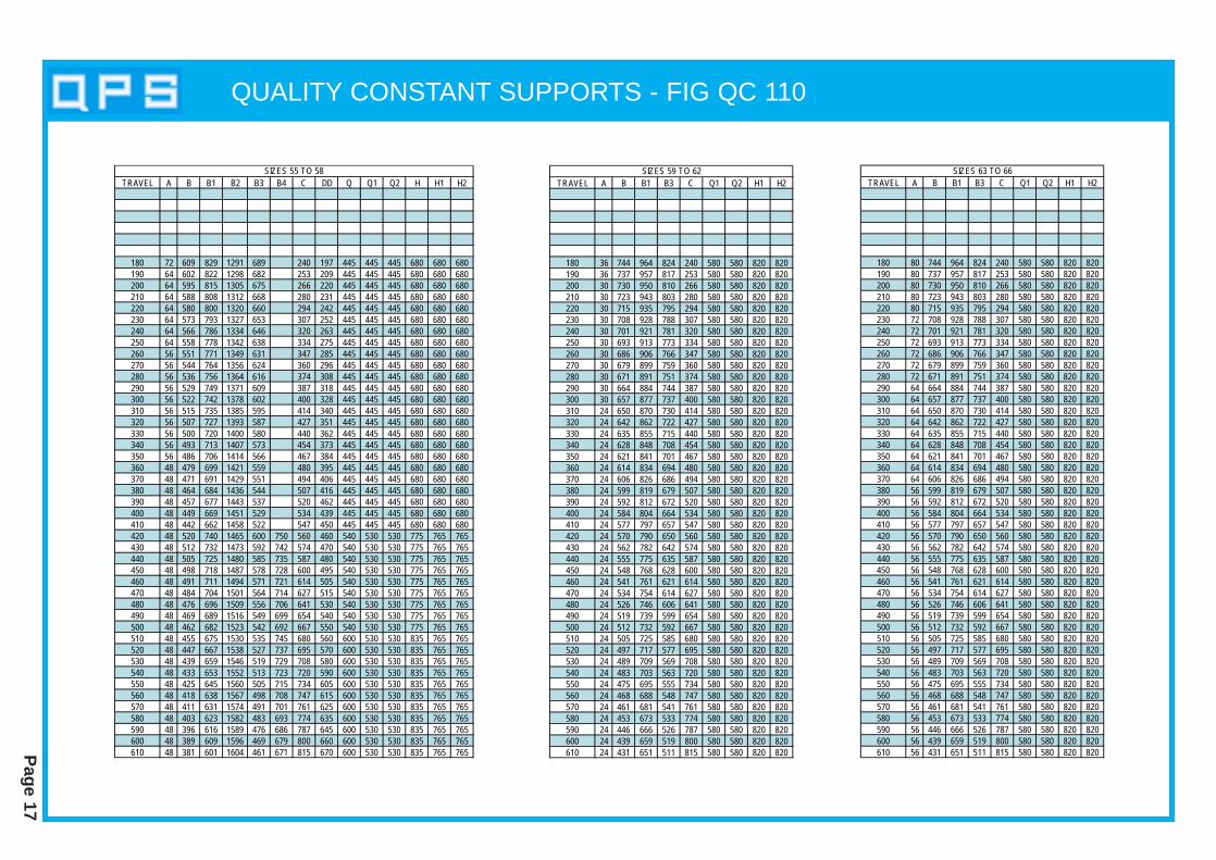
QUALITY CONSTANT SUPPORTS - FIG QC 110
Page 17
TRAVEL A B B1 B2 B3 B4 C DD Q Q1 Q2 H H1 H2
180 72 609 829 1291 689 240 197 445 445 445 680 680 680190 64 602 822 1298 682 253 209 445 445 445 680 680 680200 64 595 815 1305 675 266 220 445 445 445 680 680 680210 64 588 808 1312 668 280 231 445 445 445 680 680 680220 64 580 800 1320 660 294 242 445 445 445 680 680 680230 64 573 793 1327 653 307 252 445 445 445 680 680 680240 64 566 786 1334 646 320 263 445 445 445 680 680 680250 64 558 778 1342 638 334 275 445 445 445 680 680 680260 56 551 771 1349 631 347 285 445 445 445 680 680 680270 56 544 764 1356 624 360 296 445 445 445 680 680 680280 56 536 756 1364 616 374 308 445 445 445 680 680 680290 56 529 749 1371 609 387 318 445 445 445 680 680 680300 56 522 742 1378 602 400 328 445 445 445 680 680 680310 56 515 735 1385 595 414 340 445 445 445 680 680 680320 56 507 727 1393 587 427 351 445 445 445 680 680 680330 56 500 720 1400 580 440 362 445 445 445 680 680 680340 56 493 713 1407 573 454 373 445 445 445 680 680 680350 56 486 706 1414 566 467 384 445 445 445 680 680 680360 48 479 699 1421 559 480 395 445 445 445 680 680 680370 48 471 691 1429 551 494 406 445 445 445 680 680 680380 48 464 684 1436 544 507 416 445 445 445 680 680 680390 48 457 677 1443 537 520 462 445 445 445 680 680 680400 48 449 669 1451 529 534 439 445 445 445 680 680 680410 48 442 662 1458 522 547 450 445 445 445 680 680 680420 48 520 740 1465 600 750 560 460 540 530 530 775 765 765430 48 512 732 1473 592 742 574 470 540 530 530 775 765 765440 48 505 725 1480 585 735 587 480 540 530 530 775 765 765450 48 498 718 1487 578 728 600 495 540 530 530 775 765 765460 48 491 711 1494 571 721 614 505 540 530 530 775 765 765470 48 484 704 1501 564 714 627 515 540 530 530 775 765 765480 48 476 696 1509 556 706 641 530 540 530 530 775 765 765490 48 469 689 1516 549 699 654 540 540 530 530 775 765 765500 48 462 682 1523 542 692 667 550 540 530 530 775 765 765510 48 455 675 1530 535 745 680 560 600 530 530 835 765 765520 48 447 667 1538 527 737 695 570 600 530 530 835 765 765530 48 439 659 1546 519 729 708 580 600 530 530 835 765 765540 48 433 653 1552 513 723 720 590 600 530 530 835 765 765550 48 425 645 1560 505 715 734 605 600 530 530 835 765 765560 48 418 638 1567 498 708 747 615 600 530 530 835 765 765570 48 411 631 1574 491 701 761 625 600 530 530 835 765 765580 48 403 623 1582 483 693 774 635 600 530 530 835 765 765590 48 396 616 1589 476 686 787 645 600 530 530 835 765 765600 48 389 609 1596 469 679 800 660 600 530 530 835 765 765610 48 381 601 1604 461 671 815 670 600 530 530 835 765 765
SIZES 55 TO 58TRAVEL A B B1 B3 C Q1 Q2 H1 H2
180 36 744 964 824 240 580 580 820 820190 36 737 957 817 253 580 580 820 820200 30 730 950 810 266 580 580 820 820210 30 723 943 803 280 580 580 820 820220 30 715 935 795 294 580 580 820 820230 30 708 928 788 307 580 580 820 820240 30 701 921 781 320 580 580 820 820250 30 693 913 773 334 580 580 820 820260 30 686 906 766 347 580 580 820 820270 30 679 899 759 360 580 580 820 820280 30 671 891 751 374 580 580 820 820290 30 664 884 744 387 580 580 820 820300 30 657 877 737 400 580 580 820 820310 24 650 870 730 414 580 580 820 820320 24 642 862 722 427 580 580 820 820330 24 635 855 715 440 580 580 820 820340 24 628 848 708 454 580 580 820 820350 24 621 841 701 467 580 580 820 820360 24 614 834 694 480 580 580 820 820370 24 606 826 686 494 580 580 820 820380 24 599 819 679 507 580 580 820 820390 24 592 812 672 520 580 580 820 820400 24 584 804 664 534 580 580 820 820410 24 577 797 657 547 580 580 820 820420 24 570 790 650 560 580 580 820 820430 24 562 782 642 574 580 580 820 820440 24 555 775 635 587 580 580 820 820450 24 548 768 628 600 580 580 820 820460 24 541 761 621 614 580 580 820 820470 24 534 754 614 627 580 580 820 820480 24 526 746 606 641 580 580 820 820490 24 519 739 599 654 580 580 820 820500 24 512 732 592 667 580 580 820 820510 24 505 725 585 680 580 580 820 820520 24 497 717 577 695 580 580 820 820530 24 489 709 569 708 580 580 820 820540 24 483 703 563 720 580 580 820 820550 24 475 695 555 734 580 580 820 820560 24 468 688 548 747 580 580 820 820570 24 461 681 541 761 580 580 820 820580 24 453 673 533 774 580 580 820 820590 24 446 666 526 787 580 580 820 820600 24 439 659 519 800 580 580 820 820610 24 431 651 511 815 580 580 820 820
SIZES 59 TO 62TRAVEL A B B1 B3 C Q1 Q2 H1 H2
180 80 744 964 824 240 580 580 820 820190 80 737 957 817 253 580 580 820 820200 80 730 950 810 266 580 580 820 820210 80 723 943 803 280 580 580 820 820220 80 715 935 795 294 580 580 820 820230 72 708 928 788 307 580 580 820 820240 72 701 921 781 320 580 580 820 820250 72 693 913 773 334 580 580 820 820260 72 686 906 766 347 580 580 820 820270 72 679 899 759 360 580 580 820 820280 72 671 891 751 374 580 580 820 820290 64 664 884 744 387 580 580 820 820300 64 657 877 737 400 580 580 820 820310 64 650 870 730 414 580 580 820 820320 64 642 862 722 427 580 580 820 820330 64 635 855 715 440 580 580 820 820340 64 628 848 708 454 580 580 820 820350 64 621 841 701 467 580 580 820 820360 64 614 834 694 480 580 580 820 820370 64 606 826 686 494 580 580 820 820380 56 599 819 679 507 580 580 820 820390 56 592 812 672 520 580 580 820 820400 56 584 804 664 534 580 580 820 820410 56 577 797 657 547 580 580 820 820420 56 570 790 650 560 580 580 820 820430 56 562 782 642 574 580 580 820 820440 56 555 775 635 587 580 580 820 820450 56 548 768 628 600 580 580 820 820460 56 541 761 621 614 580 580 820 820470 56 534 754 614 627 580 580 820 820480 56 526 746 606 641 580 580 820 820490 56 519 739 599 654 580 580 820 820500 56 512 732 592 667 580 580 820 820510 56 505 725 585 680 580 580 820 820520 56 497 717 577 695 580 580 820 820530 56 489 709 569 708 580 580 820 820540 56 483 703 563 720 580 580 820 820550 56 475 695 555 734 580 580 820 820560 56 468 688 548 747 580 580 820 820570 56 461 681 541 761 580 580 820 820580 56 453 673 533 774 580 580 820 820590 56 446 666 526 787 580 580 820 820600 56 439 659 519 800 580 580 820 820610 56 431 651 511 815 580 580 820 820
SIZES 63 TO 66
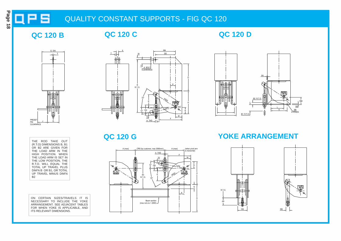
QUALITY CONSTANT SUPPORTS - FIG QC 120
Page 18
THE ROD TAKE OUT(R.T.O) DIMENSIONS B, B1OR B2 ARE GIVEN FORTHE LOAD ARM IN THEHIGH POSITION. WHENTHE LOAD ARM IS SET INTHE LOW POSITION, THER.T.O. WILL EQUAL THETOTAL UP TRAVEL PLUSDIM’N B OR B1, OR TOTALUP TRAVEL MINUS DIM’NB2
QC 120 B QC 120 C QC 120 D
YOKE ARRANGEMENTQC 120 G
ON CERTAIN SIZES/TRAVELS IT IS NECESSARY TO INCLUDE THE YOKEARRANGEMENT. SEE ADJACENT TABLESFOR WHEN YOKE IS APPLICABLE, ANDITS RELEVANT DIMENSIONS.
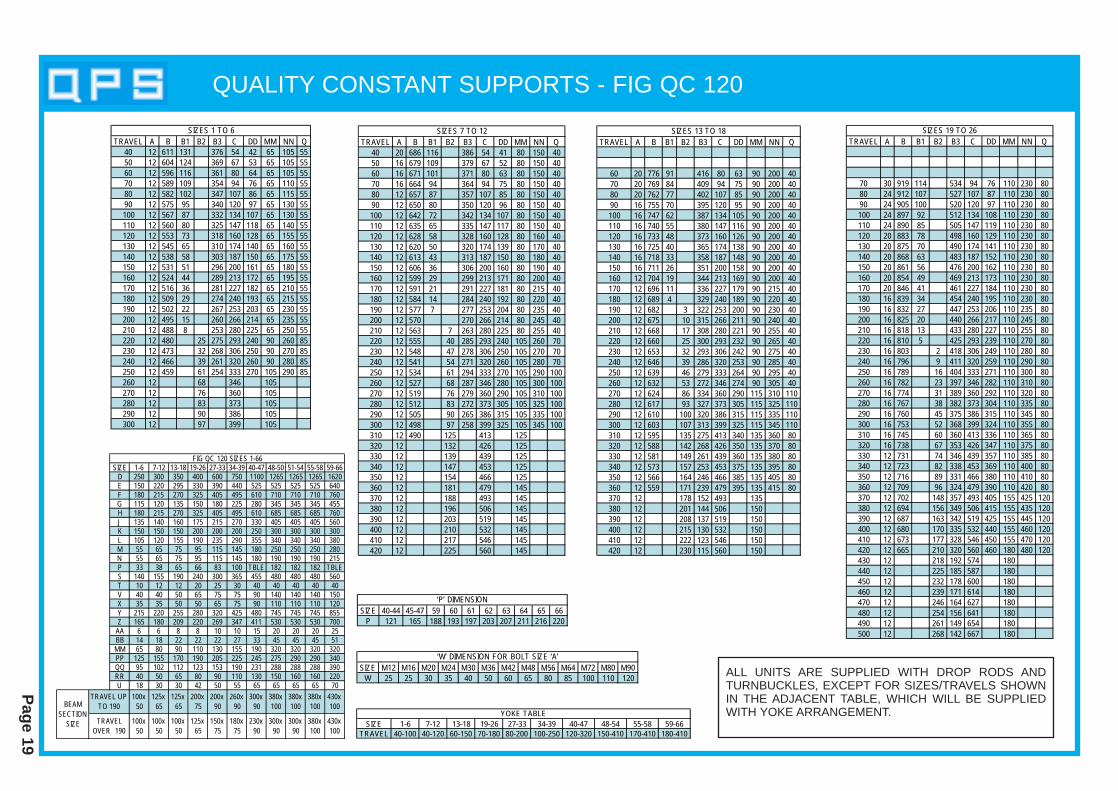
QUALITY CONSTANT SUPPORTS - FIG QC 120
Page 19
TRAVEL A B B1 B2 B3 C DD MM NN Q40 12 611 131 376 54 42 65 105 5550 12 604 124 369 67 53 65 105 5560 12 596 116 361 80 64 65 105 5570 12 589 109 354 94 76 65 110 5580 12 582 102 347 107 86 65 115 5590 12 575 95 340 120 97 65 130 55100 12 567 87 332 134 107 65 130 55110 12 560 80 325 147 118 65 140 55120 12 553 73 318 160 128 65 155 55130 12 545 65 310 174 140 65 160 55140 12 538 58 303 187 150 65 175 55150 12 531 51 296 200 161 65 180 55160 12 524 44 289 213 172 65 195 55170 12 516 36 281 227 182 65 210 55180 12 509 29 274 240 193 65 215 55190 12 502 22 267 253 203 65 230 55200 12 495 15 260 266 214 65 235 55210 12 488 8 253 280 225 65 250 55220 12 480 25 275 293 240 90 260 85230 12 473 32 268 306 250 90 270 85240 12 466 39 261 320 260 90 280 85250 12 459 61 254 333 270 105 290 85260 12 68 346 105270 12 76 360 105280 12 83 373 105290 12 90 386 105300 12 97 399 105
SIZES 1 TO 6
SIZE 1-6 7-12 13-18 19-26 27-33 34-39 40-47 48-50 51-54 55-58 59-66D 250 300 350 400 600 750 1100 1265 1265 1265 1620E 150 220 295 330 390 440 525 525 525 525 640F 180 215 270 325 405 495 610 710 710 710 760G 115 120 135 150 180 225 280 345 345 345 455H 180 215 270 325 405 495 610 685 685 685 760J 135 140 160 175 215 270 330 405 405 405 560K 150 150 150 200 200 200 250 300 300 300 300L 105 120 155 190 235 290 355 340 340 340 380M 55 65 75 95 115 145 180 250 250 250 280N 55 65 75 95 115 145 180 190 190 190 215P 33 38 65 66 83 100 TBLE 182 182 182 TBLES 140 155 190 240 300 365 455 480 480 480 560T 10 12 12 20 25 30 40 40 40 40 40V 40 40 50 65 75 75 90 140 140 140 150X 35 35 50 50 65 75 90 110 110 110 120Y 215 220 255 280 320 425 480 745 745 745 855Z 165 180 209 220 269 347 411 530 530 530 700
AA 6 6 8 8 10 10 15 20 20 20 25BB 14 18 22 22 22 27 33 45 45 45 51MM 65 80 90 110 130 155 190 320 320 320 320PP 125 155 170 190 205 225 245 275 290 290 340QQ 95 102 112 123 153 190 231 288 288 288 390RR 40 50 65 80 90 110 130 150 160 160 220U 18 30 30 42 50 55 65 65 65 65 70
TRAVEL UP TO 190
100x 50BEAM
SECTION SIZE
FIG QC 120 SIZES 1-66
125x 65
125x65
200x75
200x90
260x90
300x90
380x100
380x100
380x100
430x100
TRAVEL OVER 190
100x 50
100x 50
100x50
125x65
150x75
180x75
230x90
300x90
300x90
380x100
430x100
TRAVEL A B B1 B2 B3 C DD MM NN Q40 20 686 116 386 54 41 80 150 4050 16 679 109 379 67 52 80 150 4060 16 671 101 371 80 63 80 150 4070 16 664 94 364 94 75 80 150 4080 12 657 87 357 107 85 80 150 4090 12 650 80 350 120 96 80 150 40100 12 642 72 342 134 107 80 150 40110 12 635 65 335 147 117 80 150 40120 12 628 58 328 160 128 80 160 40130 12 620 50 320 174 139 80 170 40140 12 613 43 313 187 150 80 180 40150 12 606 36 306 200 160 80 190 40160 12 599 29 299 213 171 80 200 40170 12 591 21 291 227 181 80 215 40180 12 584 14 284 240 192 80 220 40190 12 577 7 277 253 204 80 235 40200 12 570 270 266 214 80 245 40210 12 563 7 263 280 225 80 255 40220 12 555 40 285 293 240 105 260 70230 12 548 47 278 306 250 105 270 70240 12 541 54 271 320 260 105 280 70250 12 534 61 294 333 270 105 290 100260 12 527 68 287 346 280 105 300 100270 12 519 76 279 360 290 105 310 100280 12 512 83 272 373 305 105 325 100290 12 505 90 265 386 315 105 335 100300 12 498 97 258 399 325 105 345 100310 12 490 125 413 125320 12 132 426 125330 12 139 439 125340 12 147 453 125350 12 154 466 125360 12 181 479 145370 12 188 493 145380 12 196 506 145390 12 203 519 145400 12 210 532 145410 12 217 546 145420 12 225 560 145
SIZES 7 TO 12TRAVEL A B B1 B2 B3 C DD MM NN Q
60 20 776 91 416 80 63 90 200 4070 20 769 84 409 94 75 90 200 4080 20 762 77 402 107 85 90 200 4090 16 755 70 395 120 95 90 200 40100 16 747 62 387 134 105 90 200 40110 16 740 55 380 147 116 90 200 40120 16 733 48 373 160 126 90 200 40130 16 725 40 365 174 138 90 200 40140 16 718 33 358 187 148 90 200 40150 16 711 26 351 200 158 90 200 40160 12 704 19 344 213 169 90 200 40170 12 696 11 336 227 179 90 215 40180 12 689 4 329 240 189 90 220 40190 12 682 3 322 253 200 90 230 40200 12 675 10 315 266 211 90 240 40210 12 668 17 308 280 221 90 255 40220 12 660 25 300 293 232 90 265 40230 12 653 32 293 306 242 90 275 40240 12 646 39 286 320 253 90 285 40250 12 639 46 279 333 264 90 295 40260 12 632 53 272 346 274 90 305 40270 12 624 86 334 360 290 115 310 110280 12 617 93 327 373 305 115 325 110290 12 610 100 320 386 315 115 335 110300 12 603 107 313 399 325 115 345 110310 12 595 135 275 413 340 135 360 80320 12 588 142 268 426 350 135 370 80330 12 581 149 261 439 360 135 380 80340 12 573 157 253 453 375 135 395 80350 12 566 164 246 466 385 135 405 80360 12 559 171 239 479 395 135 415 80370 12 178 152 493 135380 12 201 144 506 150390 12 208 137 519 150400 12 215 130 532 150410 12 222 123 546 150420 12 230 115 560 150
SIZES 13 TO 18TRAVEL A B B1 B2 B3 C DD MM NN Q
70 30 919 114 534 94 76 110 230 8080 24 912 107 527 107 87 110 230 8090 24 905 100 520 120 97 110 230 80100 24 897 92 512 134 108 110 230 80110 24 890 85 505 147 119 110 230 80120 20 883 78 498 160 129 110 230 80130 20 875 70 490 174 141 110 230 80140 20 868 63 483 187 152 110 230 80150 20 861 56 476 200 162 110 230 80160 20 854 49 469 213 173 110 230 80170 20 846 41 461 227 184 110 230 80180 16 839 34 454 240 195 110 230 80190 16 832 27 447 253 206 110 235 80200 16 825 20 440 266 217 110 245 80210 16 818 13 433 280 227 110 255 80220 16 810 5 425 293 239 110 270 80230 16 803 2 418 306 249 110 280 80240 16 796 9 411 320 259 110 290 80250 16 789 16 404 333 271 110 300 80260 16 782 23 397 346 282 110 310 80270 16 774 31 389 360 292 110 320 80280 16 767 38 382 373 304 110 335 80290 16 760 45 375 386 315 110 345 80300 16 753 52 368 399 324 110 355 80310 16 745 60 360 413 336 110 365 80320 16 738 67 353 426 347 110 375 80330 12 731 74 346 439 357 110 385 80340 12 723 82 338 453 369 110 400 80350 12 716 89 331 466 380 110 410 80360 12 709 96 324 479 390 110 420 80370 12 702 148 357 493 405 155 425 120380 12 694 156 349 506 415 155 435 120390 12 687 163 342 519 425 155 445 120400 12 680 170 335 532 440 155 460 120410 12 673 177 328 546 450 155 470 120420 12 665 210 320 560 460 180 480 120430 12 218 192 574 180440 12 225 185 587 180450 12 232 178 600 180460 12 239 171 614 180470 12 246 164 627 180480 12 254 156 641 180490 12 261 149 654 180500 12 268 142 667 180
SIZES 19 TO 26
SIZE 40-44 45-47 59 60 61 62 63 64 65 66P 121 165 188 193 197 203 207 211 216 220
‘P’ DIMENSION
SIZE M12 M16 M20 M24 M30 M36 M42 M48 M56 M64 M72 M80 M90W 25 25 30 35 40 50 60 65 80 85 100 110 120
‘W’ DIMENSION FOR BOLT SIZE ‘A’
SIZE 1-6 7-12 13-18 19-26 27-33 34-39 40-47 48-54 55-58 59-66TRAVEL 40-100 40-120 60-150 70-180 80-200 100-250 120-320 150-410 170-410 180-410
YOKE TABLE
ALL UNITS ARE SUPPLIED WITH DROP RODS ANDTURNBUCKLES, EXCEPT FOR SIZES/TRAVELS SHOWNIN THE ADJACENT TABLE, WHICH WILL BE SUPPLIEDWITH YOKE ARRANGEMENT.
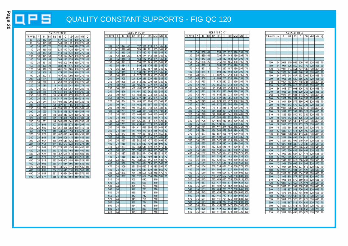
QUALITY CONSTANT SUPPORTS - FIG QC 120
Page 20
TRAVEL A B B1 B2 B3 C DD MM NN Q80 36 1182 87 547 107 88 130 275 4090 36 1175 80 540 120 99 130 275 40100 36 1167 72 532 134 109 130 275 40110 30 1160 65 525 147 120 130 275 40120 30 1153 58 518 160 131 130 275 40130 30 1145 50 510 174 142 130 275 40140 30 1138 43 503 187 153 130 275 40150 30 1131 36 496 200 164 130 275 40160 30 1124 29 489 213 175 130 275 40170 24 1116 21 481 227 185 130 275 40180 24 1109 14 474 240 196 130 275 40190 24 1102 7 467 253 208 130 275 40200 24 1095 460 266 219 130 275 40210 24 1088 7 453 280 230 130 275 40220 24 1080 15 445 293 241 130 275 40230 24 1073 22 438 306 251 130 285 40240 20 1066 29 431 320 262 130 295 40250 20 1059 36 424 333 273 130 310 40260 20 1052 43 417 346 284 130 315 40270 20 1044 51 409 360 295 130 330 40280 20 1037 58 402 373 306 130 335 40290 20 1030 65 395 386 317 130 345 40300 20 1023 72 388 399 327 130 355 40310 20 1015 80 380 413 339 130 370 40320 20 1008 87 373 426 350 130 380 40330 20 1001 94 366 439 361 130 390 40340 20 993 102 358 453 372 130 395 40350 20 986 109 351 466 383 130 415 40360 20 979 116 344 479 394 130 420 40370 20 972 173 407 493 405 180 435 110380 20 964 181 399 506 415 180 445 110390 20 957 188 392 519 425 180 455 110400 20 950 195 385 532 440 180 470 110410 20 943 202 378 546 450 180 480 110420 20 935 210 370 560 460 180 490 110430 20 927 218 362 574 470 180 500 110440 20 920 225 355 587 480 180 510 110450 20 913 232 348 600 495 180 525 110460 20 906 239 341 614 505 180 535 110470 20 899 246 334 627 515 180 545 110480 20 891 254 326 641 530 180 560 110490 20 884 261 319 654 540 180 570 110500 20 877 268 312 667 550 180 580 110
SIZES 27 TO 33 TRAVEL A B B1 B2 B3 C DD MM NN Q
100 42 1377 47 592 134 110 155 345 40110 42 1370 40 585 147 121 155 345 40120 42 1363 33 578 160 131 155 345 40130 42 1355 25 570 174 143 155 345 40140 36 1348 18 563 187 154 155 345 40150 36 1341 11 556 200 165 155 345 40160 36 1334 4 549 213 176 155 345 40170 36 1326 4 541 227 187 155 345 40180 36 1319 11 534 240 197 155 345 40190 30 1312 18 527 253 209 155 345 40200 30 1305 25 520 266 220 155 345 40210 30 1298 32 513 280 230 155 345 40220 30 1290 40 505 293 242 155 345 40230 30 1283 47 498 306 252 155 345 40240 30 1276 54 491 320 262 155 345 40250 30 1269 61 484 333 274 155 345 40260 30 1262 68 477 346 285 155 355 40270 30 1254 76 469 360 296 155 360 40280 30 1247 83 462 373 307 155 370 40290 30 1240 90 455 386 318 155 380 40300 30 1233 97 448 399 328 155 390 40310 24 1225 105 440 413 340 155 405 40320 24 1218 112 433 426 351 155 415 40330 24 1211 119 426 439 361 155 420 40340 24 1203 127 418 453 373 155 430 40350 24 1196 134 411 466 384 155 445 40360 24 1189 141 404 479 394 155 455 40370 24 1182 148 397 493 405 155 465 40380 24 1174 156 389 506 416 155 485 40390 24 1167 163 382 519 427 155 495 40400 24 1160 170 375 532 439 155 500 40410 24 1153 177 368 546 449 155 515 40420 24 1145 215 390 560 460 185 500 70430 24 1137 223 382 574 470 185 510 70440 24 1130 230 375 587 480 185 515 70450 24 1123 237 368 600 495 185 530 70460 24 1116 244 361 614 505 185 540 70470 24 1109 251 354 627 515 185 550 70480 24 1101 259 346 641 530 185 565 70490 24 1094 291 339 654 540 210 575 70500 24 1087 298 332 667 550 210 585 70510 24 305 680 210520 24 313 695 210530 24 321 708 210540 24 327 720 210550 24 335 734 210560 24 342 747 210570 24 349 761 210580 24 357 774 210590 24 364 787 210600 24 371 800 210610 24 379 815 210
SIZES 34 TO 39 TRAVEL A B B1 B2 B3 C DD MM NN Q
120 56 1858 48 738 160 132 190 395 70130 56 1850 40 730 174 144 190 395 70140 56 1843 33 723 187 154 190 395 70150 56 1836 26 716 200 165 190 395 70160 48 1829 19 709 213 176 190 395 70170 48 1821 11 701 227 187 190 395 70180 48 1814 4 694 240 198 190 395 70190 48 1807 3 687 253 210 190 395 70200 48 1800 10 680 266 220 190 395 70210 42 1793 17 673 280 231 190 395 70220 42 1785 25 665 293 243 190 395 70230 42 1778 32 658 306 253 190 395 70240 42 1771 39 651 320 264 190 395 70250 42 1764 46 644 333 275 190 395 70260 42 1757 53 637 346 286 190 395 70270 42 1749 61 629 360 297 190 395 70280 42 1742 68 622 373 308 190 395 70290 36 1735 75 615 386 319 190 395 70300 36 1728 82 608 399 329 190 395 70310 36 1720 90 600 413 341 190 405 70320 36 1713 97 593 426 352 190 415 70330 36 1706 104 586 439 363 190 425 70340 36 1698 112 578 453 375 190 435 70350 36 1691 119 571 466 386 190 450 70360 36 1684 126 564 479 396 190 455 70370 36 1677 133 557 493 407 190 465 70380 36 1669 141 549 506 416 190 485 70390 36 1662 148 542 519 429 190 495 70400 36 1655 155 535 532 441 190 500 70410 36 1648 162 528 546 451 190 515 70420 36 1640 230 550 560 461 250 515 100430 36 1632 238 542 574 471 250 525 100440 36 1625 245 535 587 482 250 535 100450 36 1618 252 528 600 493 250 550 100460 36 1611 259 521 614 505 250 560 100470 36 1604 266 514 627 515 250 570 100480 36 1596 274 506 641 527 250 580 100490 36 1589 281 499 654 537 250 590 100500 36 1582 288 492 667 548 250 600 100510 36 1575 295 485 680 559 250 615 100520 36 1567 303 477 695 571 250 625 100530 36 1559 311 469 708 582 250 635 100540 36 1553 317 463 720 592 250 645 100550 36 1545 325 455 734 604 250 660 100560 36 1538 332 448 747 613 250 665 100570 36 1531 339 441 761 625 250 680 100580 36 1523 347 433 774 636 250 690 100590 36 1516 354 426 787 647 250 700 100600 36 1509 361 419 800 658 250 715 100610 36 1501 369 411 815 670 250 725 100
SIZES 40 TO 47
TRAVEL A B B2 B3 C DD MM NN Q
150 64 2001 219 666 200 164 320 465 70160 64 1994 226 659 213 175 320 465 70170 64 1986 234 651 227 186 320 465 70180 64 1979 241 644 240 197 320 465 70190 64 1972 248 637 253 209 320 465 70200 56 1965 255 630 266 220 320 465 70210 56 1958 262 623 280 231 320 465 70220 56 1950 270 615 293 242 320 465 70230 56 1943 277 608 306 252 320 465 70240 56 1936 284 601 320 263 320 465 70250 56 1929 291 594 333 275 320 465 70260 56 1922 298 587 346 285 320 465 70270 48 1914 306 579 360 296 320 465 70280 48 1907 313 572 373 308 320 465 70290 48 1900 320 565 386 318 320 465 70300 48 1893 327 558 399 328 320 465 70310 48 1885 335 550 413 340 320 465 70320 48 1878 342 543 426 351 320 465 70330 48 1871 349 536 439 362 320 465 70340 48 1863 357 528 453 373 320 465 70350 48 1856 364 521 466 384 320 475 70360 42 1849 371 514 479 395 320 485 70370 42 1842 378 507 493 406 320 495 70380 42 1834 386 499 506 416 320 520 70390 42 1827 393 492 519 427 320 525 70400 42 1820 400 485 532 439 320 535 70410 42 1813 407 478 546 450 320 545 70420 42 1970 250 635 560 461 320 525 70430 42 1962 258 627 574 471 320 535 70440 42 1955 265 620 587 482 320 545 70450 42 1948 272 613 600 493 320 555 70460 42 1941 279 606 614 505 320 570 70470 42 1934 286 599 627 515 320 580 70480 42 1926 294 591 641 527 320 590 70490 42 1919 301 584 654 537 320 600 70500 42 1912 308 577 667 548 320 610 70510 42 1905 315 570 680 559 320 625 70520 42 1897 323 562 695 571 320 635 70530 42 1889 331 554 708 582 320 645 70540 42 1883 337 548 720 592 320 655 70550 42 1875 345 540 734 604 320 665 70560 42 1868 352 533 747 613 320 675 70570 42 1861 359 526 761 625 320 690 70580 42 1853 367 518 774 636 320 700 70590 42 1846 374 511 787 647 320 710 70600 42 1839 381 504 800 658 320 720 70610 42 1831 389 496 815 670 320 735 70
SIZES 48 TO 50
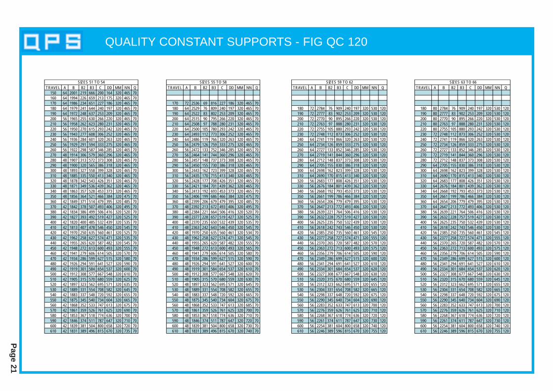
QUALITY CONSTANT SUPPORTS - FIG QC 120
Page 21
TRAVEL A B B2 B3 C DD MM NN Q150 64 2001 219 666 200 164 320 465 70160 64 1994 226 659 213 175 320 465 70170 64 1986 234 651 227 186 320 465 70180 64 1979 241 644 240 197 320 465 70190 64 1972 248 637 253 209 320 465 70200 56 1965 255 630 266 220 320 465 70210 56 1958 262 623 280 231 320 465 70220 56 1950 270 615 293 242 320 465 70230 56 1943 277 608 306 252 320 465 70240 56 1936 284 601 320 263 320 465 70250 56 1929 291 594 333 275 320 465 70260 56 1922 298 587 346 285 320 465 70270 48 1914 306 579 360 296 320 465 70280 48 1907 313 572 373 308 320 465 70290 48 1900 320 565 386 318 320 465 70300 48 1893 327 558 399 328 320 465 70310 48 1885 335 550 413 340 320 465 70320 48 1878 342 543 426 351 320 465 70330 48 1871 349 536 439 362 320 465 70340 48 1863 357 528 453 373 320 465 70350 48 1856 364 521 466 384 320 475 70360 42 1849 371 514 479 395 320 485 70370 42 1842 378 507 493 406 320 495 70380 42 1834 386 499 506 416 320 520 70390 42 1827 393 492 519 427 320 525 70400 42 1820 400 485 532 439 320 535 70410 42 1813 407 478 546 450 320 545 70420 42 1970 250 635 560 461 320 525 70430 42 1962 258 627 574 471 320 535 70440 42 1955 265 620 587 482 320 545 70450 42 1948 272 613 600 493 320 555 70460 42 1941 279 606 614 505 320 570 70470 42 1934 286 599 627 515 320 580 70480 42 1926 294 591 641 527 320 590 70490 42 1919 301 584 654 537 320 600 70500 42 1912 308 577 667 548 320 610 70510 42 1905 315 570 680 559 320 625 70520 42 1897 323 562 695 571 320 635 70530 42 1889 331 554 708 582 320 645 70540 42 1883 337 548 720 592 320 655 70550 42 1875 345 540 734 604 320 665 70560 42 1868 352 533 747 613 320 675 70570 42 1861 359 526 761 625 320 690 70580 42 1853 367 518 774 636 320 700 70590 42 1846 374 511 787 647 320 710 70600 42 1839 381 504 800 658 320 720 70610 42 1831 389 496 815 670 320 735 70
SIZES 51 TO 54TRAVEL A B B2 B3 C DD MM NN Q
170 72 2536 69 816 227 186 320 465 70180 64 2529 76 809 240 197 320 465 70190 64 2522 83 802 253 209 320 465 70200 64 2515 90 795 266 220 320 465 70210 64 2508 97 788 280 231 320 465 70220 64 2500 105 780 293 242 320 465 70230 64 2493 112 773 306 252 320 465 70240 64 2486 119 766 320 263 320 465 70250 56 2479 126 759 333 275 320 465 70260 56 2472 133 752 346 285 320 465 70270 56 2464 141 744 360 296 320 465 70280 56 2457 148 737 373 308 320 465 70290 56 2450 155 730 386 318 320 465 70300 56 2443 162 723 399 328 320 465 70310 56 2435 170 715 413 340 320 465 70320 56 2428 177 708 426 351 320 465 70330 56 2421 184 701 439 362 320 465 70340 56 2413 192 693 453 373 320 465 70350 56 2406 199 686 466 384 320 475 70360 48 2399 206 679 479 395 320 485 70370 48 2392 213 672 493 406 320 495 70380 48 2384 221 664 506 416 320 520 70390 48 2377 228 657 519 427 320 525 70400 48 2370 235 650 532 439 320 535 70410 48 2363 242 643 546 450 320 545 70420 48 1970 250 635 560 461 320 534 70430 48 1962 258 627 574 471 320 545 70440 48 1955 265 620 587 482 320 555 70450 48 1948 272 613 600 493 320 565 70460 48 1941 279 606 614 505 320 580 70470 48 1934 286 599 627 515 320 590 70480 48 1926 294 591 641 527 320 600 70490 48 1919 301 584 654 537 320 610 70500 48 1912 308 577 667 548 320 620 70510 48 1905 315 570 680 559 320 630 70520 48 1897 323 562 695 571 320 645 70530 48 1889 331 554 708 582 320 655 70540 48 1883 337 548 720 592 320 665 70550 48 1875 345 540 734 604 320 675 70560 48 1868 352 533 747 613 320 685 70570 48 1861 359 526 761 625 320 700 70580 48 1853 367 518 774 636 320 710 70590 48 1846 374 511 787 647 320 720 70600 48 1839 381 504 800 658 320 730 70610 48 1831 389 496 815 670 320 740 70
SIZES 55 TO 58TRAVEL A B B2 B3 C DD MM NN Q
180 72 2784 76 909 240 197 320 530 120190 72 2777 83 902 253 209 320 530 120200 72 2770 90 895 266 220 320 530 120210 72 2763 97 888 280 231 320 530 120220 72 2755 105 880 293 242 320 530 120230 72 2748 112 873 306 252 320 530 120240 64 2741 119 866 320 263 320 530 120250 64 2734 126 859 333 275 320 530 120260 64 2727 133 852 346 285 320 530 120270 64 2719 141 844 360 296 320 530 120280 64 2712 148 837 373 308 320 530 120290 64 2705 155 830 386 318 320 530 120300 64 2698 162 823 399 328 320 530 120310 64 2690 170 815 413 340 320 530 120320 56 2683 177 808 426 351 320 530 120330 56 2676 184 801 439 362 320 530 120340 56 2668 192 793 453 373 320 530 120350 56 2661 199 786 466 384 320 530 120360 56 2654 206 779 479 395 320 530 120370 56 2647 213 772 493 406 320 530 120380 56 2639 221 764 506 416 320 530 120390 56 2632 228 757 519 427 320 530 120400 56 2625 235 750 532 439 320 530 120410 56 2618 242 743 546 450 320 530 120420 56 2385 250 735 560 461 320 545 120430 56 2377 258 727 574 471 320 555 120440 56 2370 265 720 587 482 320 570 120450 56 2363 272 713 600 493 320 575 120460 56 2356 279 706 614 505 320 590 120470 56 2349 286 699 627 515 320 600 120480 56 2341 294 691 641 527 320 610 120490 56 2334 301 684 654 537 320 620 120500 56 2327 308 677 667 548 320 630 120510 56 2320 315 670 680 559 320 645 120520 56 2312 323 662 695 571 320 655 120530 56 2304 331 654 708 582 320 665 120540 56 2298 337 648 720 592 320 675 120550 56 2290 345 640 734 604 320 690 120560 56 2283 352 633 747 613 320 700 120570 56 2276 359 626 761 625 320 710 120580 56 2268 367 618 774 636 320 720 120590 56 2261 374 611 787 647 320 730 120600 56 2254 381 604 800 658 320 740 120610 56 2246 389 596 815 670 320 755 120
SIZES 59 TO 62TRAVEL A B B2 B3 C DD MM NN Q
180 80 2784 76 909 240 197 320 530 120190 80 2777 83 902 253 209 320 530 120200 80 2770 90 895 266 220 320 530 120210 80 2763 97 888 280 231 320 530 120220 80 2755 105 880 293 242 320 530 120230 72 2748 112 873 306 252 320 530 120240 72 2741 119 866 320 263 320 530 120250 72 2734 126 859 333 275 320 530 120260 72 2727 133 852 346 285 320 530 120270 72 2719 141 844 360 296 320 530 120280 72 2712 148 837 373 308 320 530 120290 64 2705 155 830 386 318 320 530 120300 64 2698 162 823 399 328 320 530 120310 64 2690 170 815 413 340 320 530 120320 64 2683 177 808 426 351 320 530 120330 64 2676 184 801 439 362 320 530 120340 64 2668 192 793 453 373 320 530 120350 64 2661 199 786 466 384 320 530 120360 64 2654 206 779 479 395 320 530 120370 64 2647 213 772 493 406 320 530 120380 56 2639 221 764 506 416 320 530 120390 56 2632 228 757 519 427 320 530 120400 56 2625 235 750 532 439 320 530 120410 56 2618 242 743 546 450 320 530 120420 56 2385 250 735 560 461 320 545 120430 56 2377 258 727 574 471 320 555 120440 56 2370 265 720 587 482 320 570 120450 56 2363 272 713 600 493 320 575 120460 56 2356 279 706 614 505 320 590 120470 56 2349 286 699 627 515 320 600 120480 56 2341 294 691 641 527 320 610 120490 56 2334 301 684 654 537 320 620 120500 56 2327 308 677 667 548 320 630 120510 56 2320 315 670 680 559 320 645 120520 56 2312 323 662 695 571 320 655 120530 56 2304 331 654 708 582 320 665 120540 56 2298 337 648 720 592 320 675 120550 56 2290 345 640 734 604 320 690 120560 56 2283 352 633 747 613 320 700 120570 56 2276 359 626 761 625 320 710 120580 56 2268 367 618 774 636 320 720 120590 56 2261 374 611 787 647 320 730 120600 56 2254 381 604 800 658 320 740 120610 56 2246 389 596 815 670 320 755 120
SIZES 63 TO 66

QUALITY CONSTANT SUPPORTS - FIG QC 130
Page 22
QC 130 DSHORT TRAVEL
QC 130 DLONG TRAVEL
THE ROD TAKE OUT (R.T.O.) DIMENSIONS BAND B1 ARE GIVEN FOR THE LOAD ARM INTHE HIGH POSITION. WHEN THE LOAD ARMIS SET IN THE LOW POSITION, THE R.T.O.WILL EQUAL THE TOTAL UP TRAVEL PLUSDIMENSION B, OR TOTAL UP TRAVEL MINUSDIM’N B1.
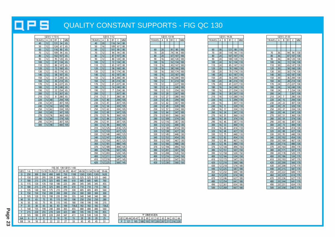
QUALITY CONSTANT SUPPORTS - FIG QC 130
Page 23
TRAVEL A B B1 C MM40 12 131 54 6550 12 124 67 6560 12 116 80 6570 12 109 94 6580 12 102 107 6590 12 95 120 65100 12 87 134 65110 12 80 147 65120 12 73 160 65130 12 65 174 65140 12 58 187 65150 12 51 200 65160 12 43 214 65170 12 36 227 65180 12 29 240 65190 12 22 254 65200 12 15 267 65210 12 8 280 65220 12 40 294 105230 12 47 307 105240 12 54 320 105250 12 62 334 105260 12 69 347 105270 12 76 360 105280 12 84 374 105290 12 91 387 105300 12 98 400 105
SIZES 1 TO 6 TRAVEL A B B1 C MM
40 20 116 54 8050 16 109 67 8060 12 101 80 8070 12 94 94 8080 12 87 107 8090 12 80 120 80100 12 72 134 80110 12 65 147 80120 12 58 160 80130 12 50 174 80140 12 43 187 80150 12 36 200 80160 12 28 214 80170 12 21 227 80180 12 14 240 80190 12 7 254 80200 12 267 80210 12 7 280 80220 12 40 294 105230 12 47 307 105240 12 54 320 105250 12 62 334 105260 12 69 347 105270 12 76 360 105280 12 84 374 105290 12 91 387 105300 12 98 400 105310 12 125 414 125320 12 133 427 125330 12 140 440 125340 12 147 454 125350 12 154 467 125360 12 181 480 145370 12 189 494 145380 12 196 507 145390 12 203 520 145400 12 211 534 145410 12 218 547 145420 12 225 560 145
SIZES 7-12TRAVEL A B B1 C MM
60 20 81 80 10070 20 74 94 10080 20 67 107 10090 16 60 120 100100 16 52 134 100110 16 45 147 100120 16 38 160 100130 16 30 174 100140 16 23 187 100150 16 16 200 100160 12 8 214 100170 12 227 100180 12 6 240 100190 12 13 254 100200 12 20 267 100210 12 27 280 100220 12 35 294 100230 12 42 307 100240 12 49 320 100250 12 57 334 100260 12 64 347 100270 12 101 360 130280 12 109 374 130290 12 116 387 130300 12 123 400 130310 12 130 414 130320 12 138 427 130330 12 145 440 130340 12 152 454 130350 12 159 467 130360 12 166 480 130370 12 194 494 150380 12 201 507 150390 12 208 520 150400 12 216 534 150410 12 223 547 150420 12 230 560 150
SIZES 13-18
SIZE 1-6 7-12 13-18 19-26 27-33 34-39 40-47 48-50 51-54 55-58 59-66D 250 300 350 400 600 750 1100 1265 1265 1265 1620E 150 220 295 330 390 440 525 525 525 525 640F 180 215 270 325 405 495 610 685 685 685 760G 115 120 135 150 180 225 280 345 345 345 455H 180 215 270 325 405 495 610 710 710 710 760J 135 140 160 175 215 270 330 405 405 405 560K 150 150 150 200 200 200 250 300 300 300 300L 105 120 155 190 235 290 355 340 340 340 380M 55 65 75 95 115 145 198 250 250 250 280N 55 65 75 95 115 145 180 190 190 190 215P 33 38 65 66 83 100 TBLE 182 182 182 TBLES 140 155 190 240 300 365 455 480 480 480 560Y 215 220 255 270 320 425 480 745 745 745 855Z 165 180 209 220 269 347 411 530 530 530 700
AA 6 6 8 8 10 10 15 20 20 20 25BB 14 18 22 22 22 27 33 45 45 45 51
FIG QC 130 SIZES 1-66
TRAVEL A B B1 C MM
60 30 121 80 11070 30 114 94 11080 24 107 107 11090 24 100 120 110100 24 92 134 110110 24 85 147 110120 20 78 160 110130 20 70 174 110140 20 63 187 110150 20 56 200 110160 20 48 214 110170 20 41 227 110180 16 34 240 110190 16 27 254 110200 16 20 267 110210 16 13 280 110220 16 5 294 110230 16 307 110240 16 9 320 110250 16 17 334 110260 16 24 347 110270 16 31 360 110280 16 39 374 110290 16 46 387 110300 16 53 400 110310 16 60 414 110320 16 68 427 110330 12 75 440 110340 12 82 454 110350 12 89 467 110360 12 96 480 110370 12 144 494 150380 12 151 507 150390 12 158 520 150400 12 166 534 150410 12 173 547 150420 12 210 560 180430 12 218 574 180440 12 225 587 180450 12 232 600 180460 12 239 614 180470 12 246 627 180480 12 254 641 180490 12 261 654 180500 12 268 667 180
SIZES 19-26TRAVEL A B B1 C MM
70 36 94 94 13080 36 87 107 13090 36 80 120 130100 36 72 134 130110 30 65 147 130120 30 58 160 130130 30 50 174 130140 30 43 187 130150 30 36 200 130160 30 28 214 130170 24 21 227 130180 24 14 240 130190 24 7 254 130200 24 267 130210 24 7 280 130220 24 15 294 130230 24 22 307 130240 20 29 320 130250 20 37 334 130260 20 44 347 130270 20 51 360 130280 20 59 374 130290 20 66 387 130300 20 73 400 130310 20 80 414 130320 20 88 427 130330 20 95 440 130340 20 102 454 130350 20 109 467 130360 20 116 480 130370 20 164 494 170380 20 171 507 170390 20 178 520 170400 20 186 534 170410 20 193 547 170420 20 200 560 170430 20 208 574 170440 20 215 587 170450 20 222 600 170460 20 229 614 170470 20 236 627 170480 20 244 641 170490 20 251 654 170500 20 258 667 170
SIZES 27-33
SIZE 40-44 45-47 59 60 61 62 63 64 65 66P 121 165 188 193 197 203 207 211 216 220
‘P’ DIMENSION

QUALITY CONSTANT SUPPORTS - FIG QC 130
Page 24
TRAVEL A B B1 C MM110 56 55 147 190120 56 48 160 190130 56 40 174 190140 56 33 187 190150 56 26 200 190160 48 18 214 190170 48 11 227 190180 48 4 240 190190 48 3 254 190200 48 10 267 190210 42 17 280 190220 42 25 294 190230 42 32 307 190240 42 39 320 190250 42 47 334 190260 42 54 347 190270 42 61 360 190280 42 69 374 190290 36 76 387 190300 36 83 400 190310 36 90 414 190320 36 98 427 190330 36 105 440 190340 36 112 454 190350 36 119 467 190360 36 126 480 190370 36 134 494 190380 36 141 507 190390 36 148 520 190400 36 156 534 190410 36 163 547 190420 36 220 560 240430 36 228 574 240440 36 235 587 240450 36 242 600 240460 36 249 614 240470 36 256 627 240480 36 264 641 240490 36 271 654 240500 36 278 667 240510 36 285 680 240520 36 293 695 240530 36 301 708 240540 36 307 720 240550 36 315 735 240560 36 322 747 240570 36 329 761 240580 36 337 774 240590 36 344 787 240600 36 351 800 240610 36 359 815 240
SIZES 40 to 47TRAVEL A B C MM
110 80 25 147 320120 72 32 160 320130 72 40 174 320140 72 47 187 320150 64 54 200 320160 64 62 214 320170 64 69 227 320180 64 76 240 320190 64 83 254 320200 56 90 267 320210 56 97 280 320220 56 105 294 320230 56 112 307 320240 56 119 320 320250 56 127 334 320260 56 134 347 320270 48 141 360 320280 48 149 374 320290 48 156 387 320300 48 163 400 320310 48 170 414 320320 48 178 427 320330 48 185 440 320340 48 192 454 320350 48 199 467 320360 42 206 480 320370 42 214 494 320380 42 221 507 320390 42 228 520 320400 42 236 534 320410 42 243 547 320420 42 250 560 320430 42 258 574 320440 42 265 587 320450 42 272 600 320460 42 279 614 320470 42 286 627 320480 42 294 641 320490 42 301 654 320500 42 308 667 320510 42 315 680 320520 42 323 695 320530 42 331 708 320540 42 337 720 320550 42 345 735 320560 42 352 747 320570 42 359 761 320580 42 367 774 320590 42 374 787 320600 42 381 800 320610 42 389 815 320
SIZES 48 to 54TRAVEL A B C MM
110 90 25 147 320120 90 32 160 320130 80 40 174 320140 80 47 187 320150 80 54 200 320160 72 62 214 320170 72 69 227 320180 72 76 240 320190 72 83 254 320200 64 90 267 320210 64 97 280 320220 64 105 294 320230 64 112 307 320240 64 119 320 320250 64 127 334 320260 56 134 347 320270 56 141 360 320280 56 149 374 320290 56 156 387 320300 56 163 400 320310 56 170 414 320320 56 178 427 320330 56 185 440 320340 56 192 454 320350 56 199 467 320360 48 206 480 320370 48 214 494 320380 48 221 507 320390 48 228 520 320400 48 236 534 320410 48 243 547 320420 48 250 560 320430 48 258 574 320440 48 265 587 320450 48 272 600 320460 48 279 614 320470 48 286 627 320480 48 294 641 320490 48 301 654 320500 48 308 667 320510 48 315 680 320520 48 323 695 320530 48 331 708 320540 48 337 720 320550 48 345 735 320560 48 352 747 320570 48 359 761 320580 48 367 774 320590 48 374 787 320600 48 381 800 320610 48 389 815 320
SIZES 55 to 58TRAVEL A B C MM
150 80 54 200 320160 80 62 214 320170 80 69 227 320180 80 76 240 320190 72 83 254 320200 72 90 267 320210 72 97 280 320220 72 105 294 320230 72 112 307 320240 64 119 320 320250 64 127 334 320260 64 134 347 320270 64 141 360 320280 64 149 374 320290 64 156 387 320300 64 163 400 320310 64 170 414 320320 56 178 427 320330 56 185 440 320340 56 192 454 320350 56 199 467 320360 56 206 480 320370 56 214 494 320380 56 221 507 320390 56 228 520 320400 56 236 534 320410 56 243 547 320420 56 250 560 320430 56 258 574 320440 56 265 587 320450 56 272 600 320460 56 279 614 320470 56 286 627 320480 56 294 641 320490 56 301 654 320500 56 308 667 320510 56 315 680 320520 56 323 695 320530 56 331 708 320540 56 337 720 320550 56 345 735 320560 56 352 747 320570 56 359 761 320580 56 367 774 320590 56 374 787 320600 56 381 800 320610 56 389 815 320
SIZES 59 to 62TRAVEL A B C MM
150 90 54 200 320160 90 62 214 320170 90 69 227 320180 80 76 240 320190 80 83 254 320200 80 90 267 320210 80 97 280 320220 80 105 294 320230 72 112 307 320240 72 119 320 320250 72 127 334 320260 72 134 347 320270 72 141 360 320280 72 149 374 320290 64 156 387 320300 64 163 400 320310 64 170 414 320320 64 178 427 320330 64 185 440 320340 64 192 454 320350 64 199 467 320360 64 206 480 320370 64 214 494 320380 56 221 507 320390 56 228 520 320400 56 236 534 320410 56 243 547 320420 56 250 560 320430 56 258 574 320440 56 265 587 320450 56 272 600 320460 56 279 614 320470 56 286 627 320480 56 294 641 320490 56 301 654 320500 56 308 667 320510 56 315 680 320520 56 323 695 320530 56 331 708 320540 56 337 720 320550 56 345 735 320560 56 352 747 320570 56 359 761 320580 56 367 774 320590 56 374 787 320600 56 381 800 320610 56 389 815 320
SIZES 63 to 66
Page 25
NOTES
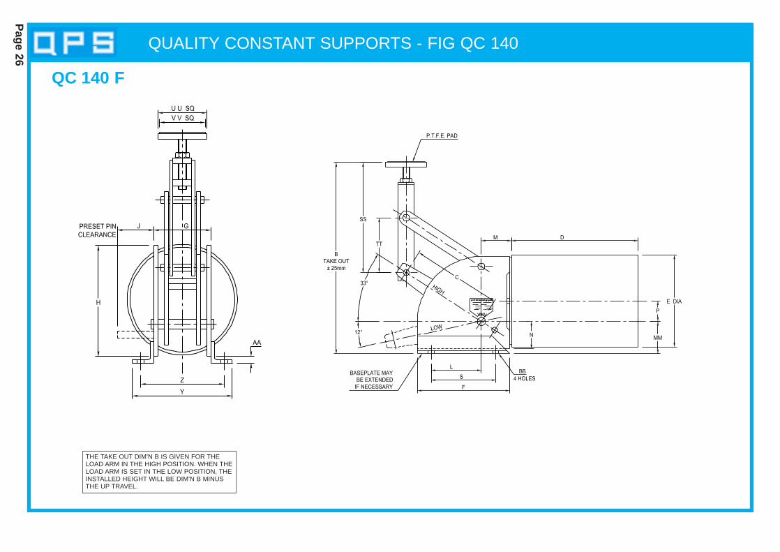
QUALITY CONSTANT SUPPORTS - FIG QC 140
Page 26
THE TAKE OUT DIM’N B IS GIVEN FOR THELOAD ARM IN THE HIGH POSITION. WHEN THELOAD ARM IS SET IN THE LOW POSITION, THEINSTALLED HEIGHT WILL BE DIM’N B MINUSTHE UP TRAVEL.
QC 140 F
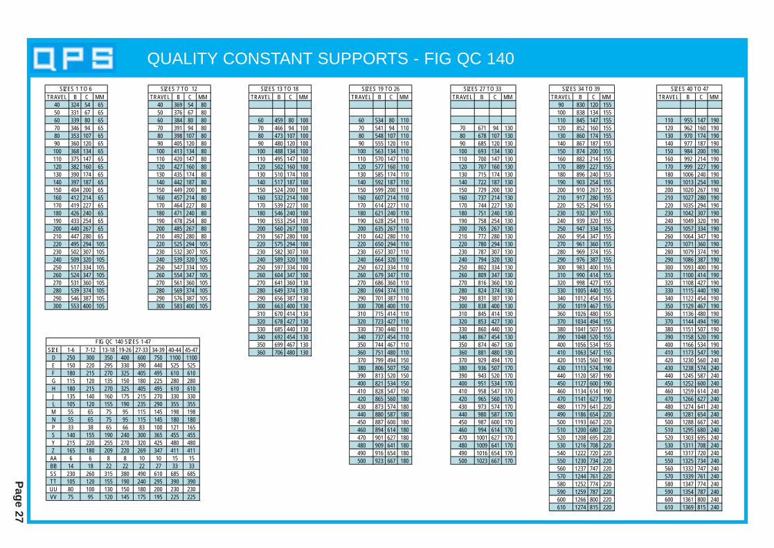
QUALITY CONSTANT SUPPORTS - FIG QC 140
Page 27
TRAVEL B C MM 40 324 54 6550 331 67 6560 339 80 6570 346 94 6580 353 107 6590 360 120 65100 368 134 65110 375 147 65120 382 160 65130 390 174 65140 397 187 65150 404 200 65160 412 214 65170 419 227 65180 426 240 65190 433 254 65200 440 267 65210 447 280 65220 495 294 105230 502 307 105240 509 320 105250 517 334 105260 524 347 105270 531 360 105280 539 374 105290 546 387 105300 553 400 105
SIZES 1 TO 6 TRAVEL B C MM
40 369 54 8050 376 67 8060 384 80 8070 391 94 8080 398 107 8090 405 120 80100 413 134 80110 420 147 80120 427 160 80130 435 174 80140 442 187 80150 449 200 80160 457 214 80170 464 227 80180 471 240 80190 478 254 80200 485 267 80210 492 280 80220 525 294 105230 532 307 105240 539 320 105250 547 334 105260 554 347 105270 561 360 105280 569 374 105290 576 387 105300 583 400 105
SIZES 7 TO 12 TRAVEL B C MM
60 459 80 10070 466 94 10080 473 107 10090 480 120 100100 488 134 100110 495 147 100120 502 160 100130 510 174 100140 517 187 100150 524 200 100160 532 214 100170 539 227 100180 546 240 100190 553 254 100200 560 267 100210 567 280 100220 575 294 100230 582 307 100240 589 320 100250 597 334 100260 604 347 100270 641 360 130280 649 374 130290 656 387 130300 663 400 130310 670 414 130320 678 427 130330 685 440 130340 692 454 130350 699 467 130360 706 480 130
SIZES 13 TO 18 TRAVEL B C MM
60 534 80 11070 541 94 11080 548 107 11090 555 120 110100 563 134 110110 570 147 110120 577 160 110130 585 174 110140 592 187 110150 599 200 110160 607 214 110170 614 227 110180 621 240 110190 628 254 110200 635 267 110210 642 280 110220 650 294 110230 657 307 110240 664 320 110250 672 334 110260 679 347 110270 686 360 110280 694 374 110290 701 387 110300 708 400 110310 715 414 110320 723 427 110330 730 440 110340 737 454 110350 744 467 110360 751 480 110370 799 494 150380 806 507 150390 813 520 150400 821 534 150410 828 547 150420 865 560 180430 873 574 180440 880 587 180450 887 600 180460 894 614 180470 901 627 180480 909 641 180490 916 654 180500 923 667 180
SIZES 19 TO 26TRAVEL B C MM
70 671 94 13080 678 107 13090 685 120 130100 693 134 130110 700 147 130120 707 160 130130 715 174 130140 722 187 130150 729 200 130160 737 214 130170 744 227 130180 751 240 130190 758 254 130200 765 267 130210 772 280 130220 780 294 130230 787 307 130240 794 320 130250 802 334 130260 809 347 130270 816 360 130280 824 374 130290 831 387 130300 838 400 130310 845 414 130320 853 427 130330 860 440 130340 867 454 130350 874 467 130360 881 480 130370 929 494 170380 936 507 170390 943 520 170400 951 534 170410 958 547 170420 965 560 170430 973 574 170440 980 587 170450 987 600 170460 994 614 170470 1001 627 170480 1009 641 170490 1016 654 170500 1023 667 170
SIZES 27 TO 33 TRAVEL B C MM
90 830 120 155100 838 134 155110 845 147 155120 852 160 155130 860 174 155140 867 187 155150 874 200 155160 882 214 155170 889 227 155180 896 240 155190 903 254 155200 910 267 155210 917 280 155220 925 294 155230 932 307 155240 939 320 155250 947 334 155260 954 347 155270 961 360 155280 969 374 155290 976 387 155300 983 400 155310 990 414 155320 998 427 155330 1005 440 155340 1012 454 155350 1019 467 155360 1026 480 155370 1034 494 155380 1041 507 155390 1048 520 155400 1056 534 155410 1063 547 155420 1105 560 190430 1113 574 190440 1120 587 190450 1127 600 190460 1134 614 190470 1141 627 190480 1179 641 220490 1186 654 220500 1193 667 220510 1200 680 220520 1208 695 220530 1216 708 220540 1222 720 220550 1230 734 220560 1237 747 220570 1244 761 220580 1252 774 220590 1259 787 220600 1266 800 220610 1274 815 220
SIZES 34 TO 39 TRAVEL B C MM
110 955 147 190120 962 160 190130 970 174 190140 977 187 190150 984 200 190160 992 214 190170 999 227 190180 1006 240 190190 1013 254 190200 1020 267 190210 1027 280 190220 1035 294 190230 1042 307 190240 1049 320 190250 1057 334 190260 1064 347 190270 1071 360 190280 1079 374 190290 1086 387 190300 1093 400 190310 1100 414 190320 1108 427 190330 1115 440 190340 1122 454 190350 1129 467 190360 1136 480 190370 1144 494 190380 1151 507 190390 1158 520 190400 1166 534 190410 1173 547 190420 1230 560 240430 1238 574 240440 1245 587 240450 1252 600 240460 1259 614 240470 1266 627 240480 1274 641 240490 1281 654 240500 1288 667 240510 1295 680 240520 1303 695 240530 1311 708 240540 1317 720 240550 1325 734 240560 1332 747 240570 1339 761 240580 1347 774 240590 1354 787 240600 1361 800 240610 1369 815 240
SIZES 40 TO 47
SIZE 1-6 7-12 13-18 19-26 27-33 34-39 40-44 45-47D 250 300 350 400 600 750 1100 1100E 150 220 295 330 390 440 525 525F 180 215 270 325 405 495 610 610G 115 120 135 150 180 225 280 280H 180 215 270 325 405 495 610 610J 135 140 160 175 215 270 330 330L 105 120 155 190 235 290 355 355M 55 65 75 95 115 145 198 198N 55 65 75 95 115 145 180 180P 33 38 65 66 83 100 121 165S 140 155 190 240 300 365 455 455Y 215 220 255 270 320 425 480 480Z 165 180 209 220 269 347 411 411
AA 6 6 8 8 10 10 15 15BB 14 18 22 22 22 27 33 33SS 230 260 315 380 490 610 685 685TT 105 120 155 190 240 295 390 390UU 80 100 130 150 180 200 230 230VV 75 95 120 145 175 195 225 225
FIG QC 140 SIZES 1-47
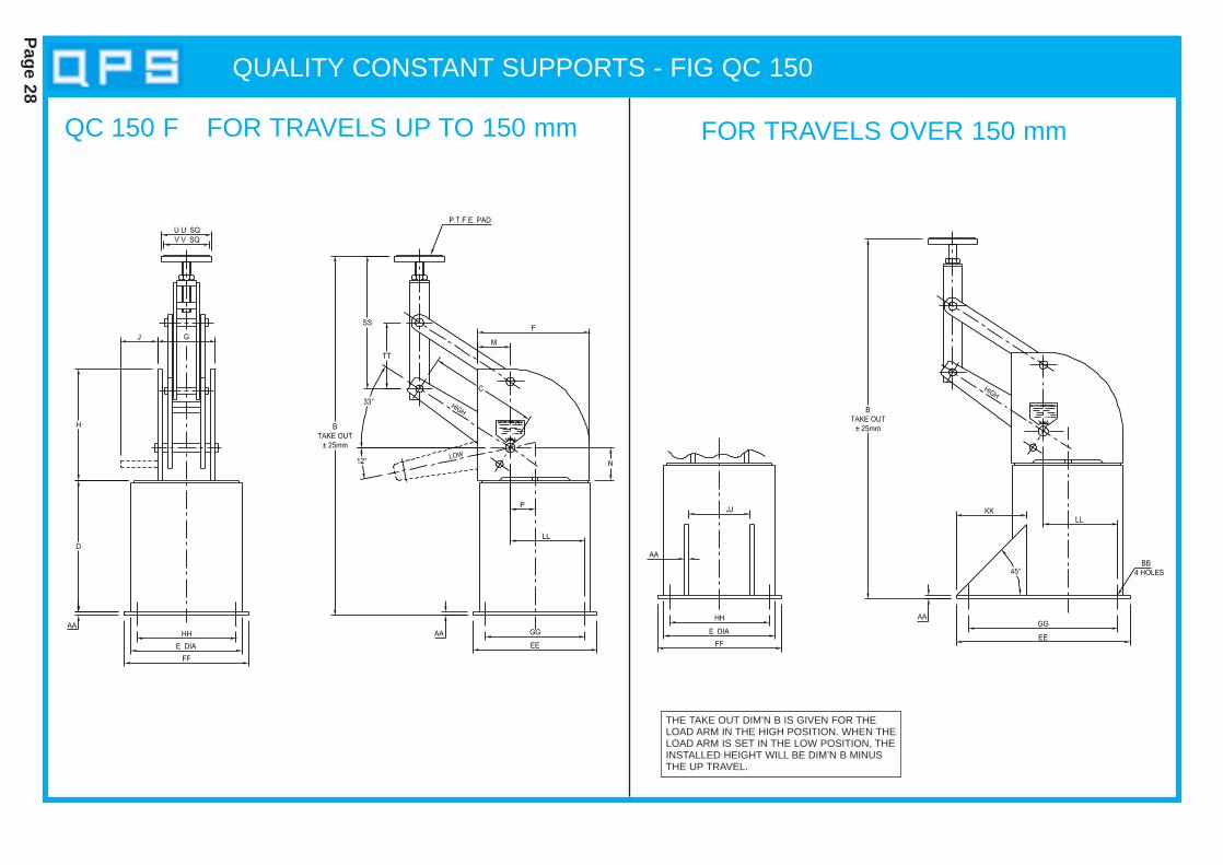
QUALITY CONSTANT SUPPORTS - FIG QC 150
Page 28
QC 150 F FOR TRAVELS UP TO 150 mm FOR TRAVELS OVER 150 mm
THE TAKE OUT DIM’N B IS GIVEN FOR THELOAD ARM IN THE HIGH POSITION. WHEN THELOAD ARM IS SET IN THE LOW POSITION, THEINSTALLED HEIGHT WILL BE DIM’N B MINUSTHE UP TRAVEL.

QUALITY CONSTANT SUPPORTS - FIG QC 150
Page 29
TRAVEL B C40 570 5450 577 6760 585 8070 592 9480 599 10790 606 120100 614 134110 621 147120 628 160130 636 174140 643 187150 650 200160 658 214170 665 227180 672 240190 679 254200 686 267210 693 280220 701 294230 708 307240 715 320250 723 334260 730 347270 737 360280 745 374290 752 387300 759 400
SIZES 1 TO 6 TRAVEL B C
40 660 5450 667 6760 675 8070 682 9480 689 10790 696 120100 704 134110 711 147120 718 160130 726 174140 733 187150 740 200160 748 214170 755 227180 762 240190 769 254200 776 267210 783 280220 791 294230 798 307240 805 320250 813 334260 820 347270 827 360280 835 374290 842 387300 849 400
SIZES 7 TO 12 TRAVEL B C
60 792 8070 799 9480 806 10790 813 120100 821 134110 828 147120 835 160130 843 174140 850 187150 857 200160 865 214170 872 227180 879 240190 886 254200 893 267210 900 280220 908 294230 915 307240 922 320250 930 334260 937 347270 944 360280 952 374290 959 387300 966 400310 973 414320 981 427330 988 440340 995 454350 1002 467360 1009 480
SIZES 13 TO 18 TRAVEL B C
60 927 8070 934 9480 941 10790 948 120100 956 134110 963 147120 970 160130 978 174140 985 187150 992 200160 1000 214170 1007 227180 1014 240190 1021 254200 1028 267210 1035 280220 1043 294230 1050 307240 1057 320250 1065 334260 1072 347270 1079 360280 1087 374290 1094 387300 1101 400310 1108 414320 1116 427330 1123 440340 1130 454350 1137 467360 1144 480370 1152 494380 1159 507390 1166 520400 1174 534410 1181 547420 1188 560430 1196 574440 1203 587450 1210 600460 1217 614470 1224 627480 1232 641490 1239 654500 1246 667
SIZES 19 TO 26TRAVEL B C
70 1266 9480 1273 10790 1280 120100 1288 134110 1295 147120 1302 160130 1310 174140 1317 187150 1324 200160 1332 214170 1339 227180 1346 240190 1353 254200 1360 267210 1367 280220 1375 294230 1382 307240 1389 320250 1397 334260 1404 347270 1411 360280 1419 374290 1426 387300 1433 400310 1440 414320 1448 427330 1455 440340 1462 454350 1469 467360 1476 480370 1484 494380 1491 507390 1498 520400 1506 534410 1513 547420 1520 560430 1528 574440 1535 587450 1542 600460 1549 614470 1556 627480 1564 641490 1571 654500 1578 667
SIZES 27 TO 33 TRAVEL B C
90 1580 120100 1588 134110 1595 147120 1602 160130 1610 174140 1617 187150 1624 200160 1632 214170 1639 227180 1646 240190 1653 254200 1660 267210 1667 280220 1675 294230 1682 307240 1689 320250 1697 334260 1704 347270 1711 360280 1719 374290 1726 387300 1733 400310 1740 414320 1748 427330 1755 440340 1762 454350 1769 467360 1776 480370 1784 494380 1791 507390 1798 520400 1806 534410 1813 547420 1820 560430 1828 574440 1835 587450 1842 600460 1849 614470 1856 627480 1864 641490 1871 654500 1878 667510 1885 680520 1893 695530 1901 708540 1907 720550 1915 734560 1922 747570 1929 761580 1937 774590 1944 787600 1951 800610 1959 815
SIZES 34 TO 39 TRAVEL B C
110 2078 147120 2085 160130 2093 174140 2100 187150 2107 200160 2115 214170 2122 227180 2129 240190 2136 254200 2143 267210 2150 280220 2158 294230 2165 307240 2172 320250 2180 334260 2187 347270 2194 360280 2202 374290 2209 387300 2216 400310 2223 414320 2231 427330 2238 440340 2245 454350 2252 467360 2259 480370 2267 494380 2274 507390 2281 520400 2289 534410 2296 547420 2303 560430 2311 574440 2318 587450 2325 600460 2332 614470 2339 627480 2347 641490 2354 654500 2361 667510 2368 680520 2376 695530 2384 708540 2390 720550 2398 734560 2405 747570 2412 761580 2420 774590 2427 787600 2434 800610 2442 815
SIZES 40 TO 47
SIZE 1-6 7-12 13-18 19-26 27-33 34-39 40-44 45-47D 250 300 350 400 600 750 1100 1100E 150 220 295 330 390 440 525 525F 180 215 270 325 405 495 610 610G 115 120 135 150 180 225 280 280H 180 215 270 325 405 495 610 610J 135 140 160 175 215 270 330 330M 55 65 75 95 115 145 180 180N 55 65 75 95 115 145 198 198P 33 38 65 66 83 100 121 165
AA 6 6 8 8 10 10 15 15BB 14 18 22 22 22 27 33 33EE 220 305 420 460 585 610 840 840FF 210 280 330 420 485 560 660 660GG 180 255 370 395 510 510 740 740HH 170 230 280 355 410 460 560 560JJ 102 108 121 133 165 206 257 257KK 80 100 170 180 230 240 360 360LL 118 153 205 244 288 330 400 445SS 230 260 315 380 490 610 685 685TT 105 120 155 190 240 295 390 390UU 80 100 130 150 180 200 230 230VV 75 95 120 145 175 195 225 225
FIG QC 150 SIZES 1-47
INSTALLATION INSTRUCTIONS
Page 30
INSTALLATION INSTRUCTIONS
QUALITY PIPE SUPPORTS
CONSTANT LOAD SUPPORT UNITSThe Constant Support Units will be attached to the steelwork by means of welding or bolting.
1. Connecting and Loading of Constant Support Units1.1 In the case of Constant Support Units of the type which utilise sling rods (Figs. QC100,
QC110, QC120 and QC130) these should be connected between the equipment support attachment and the Constant Support Unit connector (Turnbuckle or Yoke). Theload is transferred from the temporary installation condition to the Constant Support Unit byadjustment of the Turnbuckle or Yoke arrangement. The correct load setting is achieved byadjusting the Turnbuckle or Yoke arrangement until the preset pin (painted red) is easilyremoved.
1.2 In the case of Constant Support Units of the type which support the equipment from below(Figs. QC140 and QC150) the Constant Support Unit is positioned between the equipmentsupport bracket and supporting steelwork, any differences in height being accommodatedby use of the height adjusting nut. The load is transferred from the temporary installation condition to the Constant Support Unit by further adjustment of theheight adjusting nut. The correct load setting is achieved by rotation of the height adjustingnut until the preset pin (painted red) is easily removed.
Note: The red painted preset pin should normally remain in position for any pre-commissioning overload conditions, but must be removed prior to operation and storedfor possible future use.
2. Load AdjustmentIn the event that the load is greater or lesser than the load for which the Constant SupportUnit was designed and calibrated, it will be necessary to make use of the load adjustmentfacility. The load adjuster allows for an increase or decrease of load carrying capacity of plusor minus 20% of the mean load. Rotating the load adjuster nut in the appropriate directionwill increase or decrease the load accordingly. The load adjustment scale is calibrated in 2% divisions.
3. OperationPrior to start up the following checks must be carried out:
3.1 All preset pins are to be removed and stored.3.2 The Constant Support Unit travel indicator is set at the correct cold setting.3.3 During normal operation, the unit travel indicator should be at the correct “hot” position.3.4 A periodic check during the first few months of operation should be made to ensure that any
movement is within the travel range of the Constant Support Unit, minor adjustments may befound to be necessary during this time.
4. Disconnecting and Unloading of Constant Support Units4.1 Reverse the above instructions until the red painted preset pin can be easily replaced.
Variable S pringSupport s
Section 2
Variable spring support units are devices used to support pipework which is subject tovertical displacement because of temperature changes or subsidence. It isrecommended that a variable spring support unit only be used when the load variationis less than 25% from cold to hot load and that the displacement is small, up to 50 mm.Where the conditions are out of this criteria a QUALITY PIPE SUPPORTS constantspring support should be considered. Practical and technical advice is available fromQUALITY PIPE SUPPORTS.
All units are pre-set to their cold load. Each unit will have been checked through its totalworking range and its required working range. The variable spring unit will be tested ona specialised test rig which is calibrated back to a national standard.
The variable spring support finish is available as follows:
l Hammer finish paintl Hot dip galvanised l Customer specific paint finish.
Spring coils are plastic coated on standard galvanized units.
Q.P.S. variable spring units are produced in high quality carbon steel, but we are ableto offer units from austenitic stainless steel and various alloy steels where required.
Where a spring unit is required which is not covered by the Q.P.S. range, our technicaldepartment will design a unit for your particular requirement.
All Q.P.S. variable spring support units are capable of supporting pipework that can besubjected to hydrostatic test loads up to two times the working load of the unit.
ORDERINGWhen ordering please specify:
1. Q.V. number, e.g. (Q.V. 2)2. Model, e.g. (A, B, D etc.)3. Size (taken from selection table)4. Thread details5. Vertical movement and direction of movement, e.g. cold to hot, 16 mm up6. Preset load (Q.P.S. can calculate this for you given the information as above)7. If Hydrostatic stops are required8. Protective finish9. Marking (identification) number
10. Distance between rod centres and total load for model “G”.
Page 31
DESCRIPTION
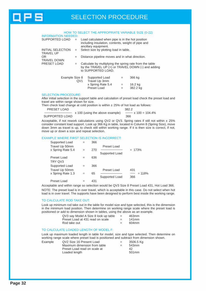
Page 32
HOW TO SELECT THE APPROPRIATE VARIABLE SIZE (0-22)INFORMATION NEEDED:SUPPORTED LOAD = Load calculated when pipe is in the hot position
including insulation, contents, weight of pipe andancillary equipment.
INITIAL SELECTION = Select size by plotting load in table.TRAVEL UPOR = Distance pipeline moves and in what direction.TRAVEL DOWNPRESET LOAD = Calculate by multiplying the spring rate from the table
by the TRAVEL UP (+) or TRAVEL DOWN (-) and addingto SUPPORTED LOAD.
Example Size 8 Supported Load = 366 kgQV1 Travel Up 3mm
x Spring Rate 5.4 = 16.2 kgPreset Load = 382.2 kg
SELECTION PROCEDURE:After initial selection in the support table and calculation of preset load check the preset load andtravel are within range shown for size.Then check load change at cold position is within ± 25% of hot load as follows:
PRESET LOAD 382.2x 100 (using the above example) x 100 = 104.4%
SUPPORTED LOAD 366Acceptable, if not rework calculations using QV2 or QV3. Spring rates if still not within ± 25%consider constant load support. Look up 366 Kg in table, located in Column 8 (Spring Size), movedown 3mm as travel is up, to check still within working range. If it is then size is correct, if not,move up or down a size and repeat selection.
EXAMPLE WHERE FIRST SELECTION IS INCORRECT:Supported Load = 366Travel Up 50mm Preset Loadx Spring Rate 5.4 = 270 = 173%
Supported LoadPreset Load = 636TRY QV3Supported Load = 366Travel Up 50mm Preset Load 431x Spring Rate 1.3 = 65 = 118%
Supported Load 366Preset Load = 431
Acceptable and within range so selection would be QV3 Size 8 Preset Load 431, Hot Load 366.NOTE: The preset load is in over travel, which is acceptable in this case. Do not select when hotload is in over travel. The supports have been designed to perform best inside the working range.
TO CALCULATE ROD TAKE OUT:Look up minimum rod take out in the table for model size and type selected, this is the dimensionin the minimum load position. Then determine on working range scale where the preset load ispositioned or add to dimension shown in tables, using the above as an example.
QV3 say Model A Size 8 look up table = 463mmPreset Load at 431 read on scale = 141mmRod take out = 604mm
TO CALCULATE LOADED LENGTH OF MODEL F:Look up maximum loaded length in table for model, size and type selected. Then determine onworking range scale where preset load is positioned and subtract from dimension shown.Example QV2 Size 16 Present Load = 3506.5 Kg
Maximum dimension from table = 543mmPreset Load read on scale at 42Loaded length 501mm
SELECTION PROCEDURE
Page 33
Variable Spring SupportsDiagrams and Tables
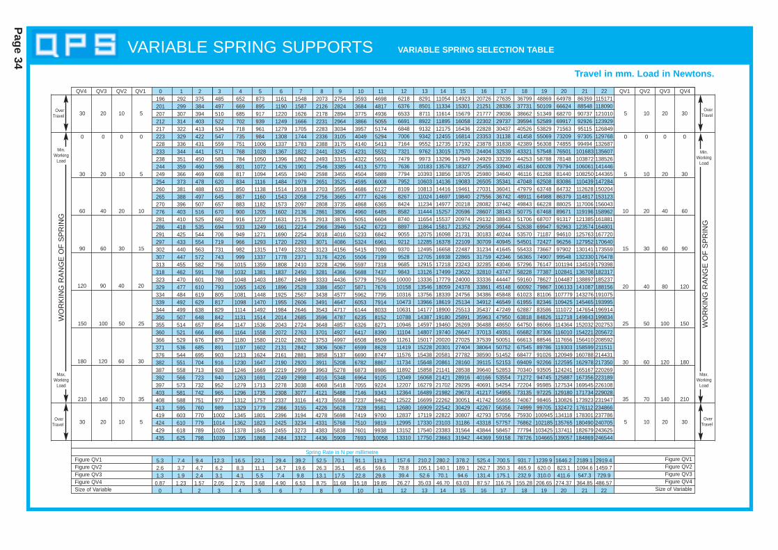
Page 34
VARIABLE SPRING SUPPORTS VARIABLE SPRING SELECTION T ABLE
QV4 QV3
Figure QV1Figure QV2Figure QV3Figure QV4Size of Variable
QV2 QV1 QV2 QV3 QV4
30 20 10 5
0 0 0 0
30 20 10 5
60 40 20 10
90 60 30 15
120 90 40 20
WO
RK
ING
RA
NG
E O
F S
PR
ING
150 100 50 25
180 120 60 30
210 140 70 35
30 20 10 5
0 0 0 0
5 10 20 30
10 20 40 60
15 30 60 90
20 40 80 120
25 50 100 150
30 60 120 180
35 70 140 210
5 10 20 30
Travel in mm. Load in Newtons.W
OR
KIN
G R
AN
GE
OF
SP
RIN
G
OverTravel
OverTravel
Min.Working
Load
Max.Working
Load
Figure QV1Figure QV2Figure QV3Figure QV4
Size of Variable
OverTravel
Max.Working
Load
Min.Working
Load
OverTravel5 10 20 30
QV112 13 14 15 16 17 18 19 20 21 226218 8291 11054 14923 20726 27635 36799 48869 64978 86359 1151716376 8501 11334 15301 21251 28336 37731 50109 66624 88548 1180906533 8711 11614 15679 21777 29036 38662 51349 68270 90737 1210106691 8922 11895 16058 22302 29737 39594 52589 69917 92926 1239296848 9132 12175 16436 22828 30437 40526 53829 71563 95115 1268497006 9342 12455 16814 23353 31138 41458 55069 73209 97305 1297687164 9552 12735 17192 23878 31838 42389 56308 74855 99494 1326877321 9762 13015 17570 24404 32539 43321 57548 76501 101683 1356077479 9973 13296 17949 24929 33239 44253 58788 78148 103872 1385267636 10183 13576 18327 25455 33940 45184 60028 79794 106061 1414467794 10393 13856 18705 25980 34640 46116 61268 81440 108250 1443657952 10603 14136 19083 26505 35341 47048 62508 83086 110439 1472848109 10813 14416 19461 27031 36041 47979 63748 84732 112628 1502048267 11024 14697 19840 27556 36742 48911 64988 86379 114817 1531238424 11234 14977 20218 28082 37442 49843 66228 88025 117006 1560438582 11444 15257 20596 28607 38143 50775 67468 89671 119196 1589628740 11654 15537 20974 29132 38843 51706 68707 91317 121385 1618818897 11864 15817 21352 29658 39544 52638 69947 92963 123574 1648019055 12075 16098 21731 30183 40244 53570 71187 94610 125763 1677209212 12285 16378 22109 30709 40945 54501 72427 96256 127952 1706409370 12495 16658 22487 31234 41645 55433 73667 97902 130141 1735599528 12705 16938 22865 31759 42346 56365 74907 99548 132330 1764789685 12915 17218 23243 32285 43046 57296 76147 101194 134519 1793989843 13126 17499 23622 32810 43747 58228 77387 102841 136708 182317
10000 13336 17779 24000 33336 44447 59160 78627 104487 138897 18523710158 13546 18059 24378 33861 45148 60092 79867 106133 141087 18815610316 13756 18339 24756 34386 45848 61023 81106 107779 143276 19107510473 13966 18619 25134 34912 46549 61955 82346 109425 145465 19399510631 14177 18900 25513 35437 47249 62887 83586 111072 147654 19691410788 14387 19180 25891 35963 47950 63818 84826 112718 149843 19983410946 14597 19460 26269 36488 48650 64750 86066 114364 152032 20275311104 14807 19740 26647 37013 49351 65682 87306 116010 154221 20567211261 15017 20020 27025 37539 50051 66613 88546 117656 156410 20859211419 15228 20301 27404 38064 50752 67545 89786 119303 158599 21151111576 15438 20581 27782 38590 51452 68477 91026 120949 160788 21443111734 15648 20861 28160 39115 52153 69409 92266 122595 162978 21735011892 15858 21141 28538 39640 52853 70340 93505 124241 165167 22026912049 16068 21421 28916 40166 53554 71272 94745 125887 167356 22318912207 16279 21702 29295 40691 54254 72204 95985 127534 169545 22610812364 16489 21982 29673 41217 54955 73135 97225 129180 171734 22902812522 16699 22262 30051 41742 55655 74067 98465 130826 173923 23194712680 16909 22542 30429 42267 56356 74999 99705 132472 176112 23486612837 17119 22822 30807 42793 57056 75930 100945 134118 178301 23778612995 17330 23103 31186 43318 57757 76862 102185 135765 180490 24070513152 17540 23383 31564 43844 58457 77794 103425 137411 182679 24362513310 17750 23663 31942 44369 59158 78726 104665 139057 184869 246544
157.6 210.2 280.2 378.2 525.4 700.5 931.7 1239.9 1646.2 2189.1 2919.478.8 105.1 140.1 189.1 262.7 350.3 465.9 620.0 823.1 1094.6 1459.739.4 52.6 70.1 94.6 131.4 175.1 232.9 310.0 411.6 547.3 729.9
26.27 35.03 46.70 63.03 87.57 116.75 155.28 206.65 274.37 364.85 486.5712 13 14 15 16 17 18 19 20 21 22
0 1 2 3 4 5 6 7 8 9 10 11196 292 375 485 652 873 1161 1548 2073 2754 3593 4698201 299 384 497 669 895 1190 1587 2126 2824 3684 4817207 307 394 510 685 917 1220 1626 2178 2894 3775 4936212 314 403 522 702 939 1249 1666 2231 2964 3866 5055217 322 413 534 718 961 1279 1705 2283 3034 3957 5174223 329 422 547 735 984 1308 1744 2336 3105 4049 5294228 336 431 559 751 1006 1337 1783 2388 3175 4140 5413233 344 441 571 768 1028 1367 1822 2441 3245 4231 5532238 351 450 583 784 1050 1396 1862 2493 3315 4322 5651244 359 460 596 801 1072 1426 1901 2546 3385 4413 5770249 366 469 608 817 1094 1455 1940 2598 3455 4504 5889254 373 478 620 834 1116 1484 1979 2651 3525 4595 6008260 381 488 633 850 1138 1514 2018 2703 3595 4686 6127265 388 497 645 867 1160 1543 2058 2756 3665 4777 6246270 396 507 657 883 1182 1573 2097 2808 3735 4868 6365276 403 516 670 900 1205 1602 2136 2861 3806 4960 6485281 410 525 682 916 1227 1631 2175 2913 3876 5051 6604286 418 535 694 933 1249 1661 2214 2966 3946 5142 6723291 425 544 706 949 1271 1690 2254 3018 4016 5233 6842297 433 554 719 966 1293 1720 2293 3071 4086 5324 6961302 440 563 731 982 1315 1749 2332 3123 4156 5415 7080307 447 572 743 999 1337 1778 2371 3176 4226 5506 7199313 455 582 756 1015 1359 1808 2410 3228 4296 5597 7318318 462 591 768 1032 1381 1837 2450 3281 4366 5688 7437323 470 601 780 1048 1403 1867 2489 3333 4436 5779 7556329 477 610 793 1065 1426 1896 2528 3386 4507 5871 7676334 484 619 805 1081 1448 1925 2567 3438 4577 5962 7795339 492 629 817 1098 1470 1955 2606 3491 4647 6053 7914344 499 638 829 1114 1492 1984 2646 3543 4717 6144 8033350 507 648 842 1131 1514 2014 2685 3596 4787 6235 8152355 514 657 854 1147 1536 2043 2724 3648 4857 6326 8271360 521 666 866 1164 1558 2072 2763 3701 4927 6417 8390366 529 676 879 1180 1580 2102 2802 3753 4997 6508 8509371 536 685 891 1197 1602 2131 2842 3806 5067 6599 8628376 544 695 903 1213 1624 2161 2881 3858 5137 6690 8747382 551 704 916 1230 1647 2190 2920 3911 5208 6782 8867387 558 713 928 1246 1669 2219 2959 3963 5278 6873 8986392 566 723 940 1263 1691 2249 2998 4016 5348 6964 9105397 573 732 952 1279 1713 2278 3038 4068 5418 7055 9224403 581 742 965 1296 1735 2308 3077 4121 5488 7146 9343408 588 751 977 1312 1757 2337 3116 4173 5558 7237 9462413 595 760 989 1329 1779 2366 3155 4226 5628 7328 9581419 603 770 1002 1345 1801 2396 3194 4278 5698 7419 9700424 610 779 1014 1362 1823 2425 3234 4331 5768 7510 9819429 618 789 1026 1378 1845 2455 3273 4383 5838 7601 9938435 625 798 1039 1395 1868 2484 3312 4436 5909 7693 10058
5.3 7.4 9.4 12.3 16.5 22.1 29.4 39.2 52.5 70.1 91.1 119.12.6 3.7 4.7 6.2 8.3 11.1 14.7 19.6 26.3 35.1 45.6 59.61.3 1.9 2.4 3.1 4.1 5.5 7.4 9.8 13.1 17.5 22.8 29.8
0.87 1.23 1.57 2.05 2.75 3.68 4.90 6.53 8.75 11.68 15.18 19.850 1 2 3 4 5 6 7 8 9 10 11
Spring Rate in N per millimetre

Page 35
QUALITY PIPE SUPPORTS VARIABLE SPRING SELECTION T ABLE
QV4 QV3 QV2 QV1 QV1 QV2 QV3 QV4
30 20 10 5
0 0 0 0
30 20 10 5
60 40 20 10
90 60 30 15
120 80 40 20
150 100 50 25
180 120 60 30
210 140 70 35
30 20 10 5
5 10 20 30
0 0 0 0
5 10 20 30
10 20 40 60
15 30 60 90
20 40 80 120
25 50 100 150
30 60 120 180
35 70 140 210
5 10 20 30
Travel in mm. Load in kilograms.
WO
RK
ING
RA
NG
E O
F S
PR
ING
WO
RK
ING
RA
NG
E O
F S
PR
ING
OverTravel
OverTravel
OverTravel
OverTravel
Min.Working
Load
Max.Working
Load
Min.Working
Load
Max.Working
Load
Figure QV1Figure QV2Figure QV3Figure QV4Size of Variable
Figure QV1Figure QV2Figure QV3Figure QV4
Size of Variable
0 1 2 3 4 5 6 7 8 9 10 1120.0 29.0 38.0 49.0 66 88 118 158 211 282 366 47920.5 29.8 39.0 50.3 68 90 121 162 216 289 375 49121.1 30.5 39.9 51.5 69 92 124 166 222 296 384 50321.6 31.3 40.9 52.8 71 95 127 170 227 303 394 51522.1 32.0 41.8 54.0 72 97 130 174 233 310 403 52722.7 32.8 42.8 55.3 74 99 133 178 238 318 412 54023.2 33.5 43.8 56.5 76 101 136 182 243 325 421 55223.7 34.3 44.7 57.8 77 103 139 186 249 332 430 56424.2 35.0 45.7 59.0 79 106 142 190 254 339 440 57624.8 35.8 46.6 60.3 80 108 145 194 260 346 449 58825.3 36.5 47.6 61.5 82 110 148 198 265 353 458 60025.8 37.3 48.6 62.8 84 112 151 202 270 360 467 61226.4 38.0 49.5 64.0 85 114 154 206 276 367 476 62426.9 38.8 50.5 65.3 87 117 157 210 281 374 486 63627.4 39.5 51.4 66.5 88 119 160 214 287 381 495 64828.0 40.3 52.4 67.8 90 121 163 218 292 389 504 66128.5 41.0 53.4 69.0 92 123 166 222 297 396 513 67329.0 41.8 54.3 70.3 93 125 169 226 303 403 522 68529.5 42.5 55.3 71.5 95 128 172 230 308 410 532 69730.1 43.3 56.2 72.8 96 130 175 234 314 417 541 70930.6 44.0 57.2 74.0 98 132 178 238 319 424 550 72131.1 44.8 58.2 75.3 100 134 181 242 324 431 559 73331.7 45.5 59.1 76.5 101 136 184 246 330 438 568 74532.2 46.3 60.1 77.8 103 139 187 250 335 445 578 75732.7 47.0 61.0 79.0 104 141 190 254 341 452 587 76933.3 47.8 62.0 80.3 106 143 193 258 346 460 596 78233.8 48.5 63.0 81.5 108 145 196 262 351 467 605 79434.3 49.3 63.9 82.8 109 147 199 266 357 474 614 80634.8 50.0 64.9 84.0 111 150 202 270 362 481 624 81835.4 50.8 65.8 85.3 112 152 205 274 368 488 633 83035.9 51.5 66.8 86.5 114 154 208 278 373 495 642 84236.4 52.3 67.8 87.8 116 156 211 282 378 502 651 85437.0 53.0 68.7 89.0 117 158 214 286 384 509 660 86637.5 53.8 69.7 90.3 119 161 217 290 389 516 670 87838.0 54.5 70.6 91.5 120 163 220 294 395 523 679 89038.6 55.3 71.6 92.8 122 165 223 298 400 531 688 90339.1 56.0 72.6 94.0 124 167 226 302 405 538 697 91539.6 56.8 73.5 95.3 125 169 229 306 411 545 706 92740.1 57.5 74.5 96.5 127 172 232 310 416 552 716 93940.7 58.3 75.4 97.8 128 174 235 314 422 559 725 95141.2 59.0 76.4 99.0 130 176 238 318 427 566 734 96341.7 59.8 77.4 100.3 132 178 241 322 432 573 743 97542.3 60.5 78.3 101.5 133 180 244 326 438 580 752 98742.8 61.3 79.3 102.8 135 183 247 330 443 587 762 99943.3 62.0 80.2 104.0 136 185 250 334 449 594 771 101143.9 62.8 81.2 105.3 138 187 253 338 454 602 780 1024
0.53 0.75 0.96 1.25 1.60 2.2 3.0 4.0 5.4 7.1 9.2 12.10.27 0.38 0.48 0.63 0.80 1.1 1.5 2.0 2.7 3.6 4.6 6.10.13 0.19 0.24 0.31 0.40 0.6 0.8 1.0 1.4 1.8 2.3 3.00.09 0.13 0.16 0.21 0.27 0.37 0.50 0.67 0.90 1.18 1.53 2.02
0 1 2 3 4 5 6 7 8 9 10 11
12 13 14 15 16 17 18 19 20 21 22634 845 1127 1521 2113 2818 3752 4983 6625 8806 11744650 866 1156 1560 2167 2889 3847 5109 6793 9029 12042666 888 1184 1598 2220 2961 3942 5236 6961 9252 12339682 909 1213 1637 2274 3032 4037 5362 7129 9476 12637698 931 1241 1675 2327 3104 4132 5489 7297 9699 12934714 952 1270 1714 2381 3175 4227 5615 7465 9922 13232730 973 1299 1753 2435 3246 4322 5741 7633 10145 13530746 995 1327 1791 2488 3318 4417 5868 7801 10368 13827762 1016 1356 1830 2542 3389 4512 5994 7969 10592 14125778 1038 1384 1868 2595 3461 4607 6121 8137 10815 14422794 1059 1413 1907 2649 3532 4702 6247 8305 11038 14720810 1080 1442 1946 2703 3603 4797 6373 8473 11261 15018826 1102 1470 1984 2756 3675 4892 6500 8641 11484 15315842 1123 1499 2023 2810 3746 4987 6626 8809 11708 15613858 1145 1527 2061 2863 3818 5082 6753 8977 11931 15910874 1166 1556 2100 2917 3889 5177 6879 9145 12154 16208890 1187 1585 2139 2971 3960 5272 7005 9313 12377 16506906 1209 1613 2177 3024 4032 5367 7132 9481 12600 16803922 1230 1642 2216 3078 4103 5462 7258 9649 12824 17101938 1252 1670 2254 3131 4175 5557 7385 9817 13047 17398954 1273 1699 2293 3185 4246 5652 7511 9985 13270 17696970 1294 1728 2332 3239 4317 5747 7637 10153 13493 17994986 1316 1756 2370 3292 4389 5842 7764 10321 13716 18291
1002 1337 1785 2409 3346 4460 5937 7890 10489 13940 185891018 1359 1813 2447 3399 4532 6032 8017 10657 14163 188861034 1380 1842 2486 3453 4603 6127 8143 10825 14386 191841050 1401 1871 2525 3507 4674 6222 8269 10993 14609 194821066 1423 1899 2563 3560 4746 6317 8396 11161 14832 197791082 1444 1928 2602 3614 4817 6412 8522 11329 15056 200771098 1466 1956 2640 3667 4889 6507 8649 11497 15279 203741114 1487 1985 2679 3721 4960 6602 8775 11665 15502 206721130 1508 2014 2718 3775 5031 6697 8901 11833 15725 209701146 1530 2042 2756 3828 5103 6792 9028 12001 15948 212671162 1551 2071 2795 3882 5174 6887 9154 12169 16172 215651178 1573 2099 2833 3935 5246 6982 9281 12337 16395 218621194 1594 2128 2872 3989 5317 7077 9407 12505 16618 221601210 1615 2157 2911 4043 5388 7172 9533 12673 16841 224581226 1637 2185 2949 4096 5460 7267 9660 12841 17064 227551242 1658 2214 2988 4150 5531 7362 9786 13009 17288 230531258 1680 2242 3026 4203 5603 7457 9913 13177 17511 233501274 1701 2271 3065 4257 5674 7552 10039 13345 17734 236481290 1722 2300 3104 4311 5745 7647 10165 13513 17957 239461306 1744 2328 3142 4364 5817 7742 10292 13681 18180 242431322 1765 2357 3181 4418 5888 7837 10418 13849 18404 245411338 1787 2385 3219 4471 5960 7932 10545 14017 18627 248381354 1808 2414 3258 4525 6031 8027 10671 14185 18850 25136
16.0 21.4 28.6 38.6 53.6 71.4 95.0 126.4 168.0 223.2 297.68.0 10.7 14.3 19.3 26.8 35.7 47.5 63.2 84.0 111.6 148.84.0 5.4 7.2 9.7 13.4 17.9 23.8 31.6 42.0 55.8 74.4
2.67 3.57 4.77 6.43 8.93 11.90 15.83 21.07 28.00 37.20 49.6012 13 14 15 16 17 18 19 20 21 22
Spring Rate in kgs per millimetre

Page 36
O
W A
LOADEDLENGTH
’Y’
P.C.D.
W
MODEL ’D’MODEL ’C’
A
SEE MODEL ’F’ FOR
MODEL ’H’
OTHER DETAILS
RADIUS TO SUITCUSTOMERSREQUIREMENTS
MODEL ’K’
OTHER DETAILSSEE MODEL ’F’ FOR
P
J
RODTAKEOUT
AA
O O
W
D DIAB
T
C
G
Rod Take Out (at Load Position)
T B
C
LOADEDLENGTH
’H’A
W
O
FLOAD FLANGE
(P.T.F.E. SLIDER OPTIONAL)
MODEL ’B’
BEFORE SELECTING THE SIZEWORKING LOAD MUST BE HALVEDNOTE : ON TYPE ’G’ UNITS THE
O
W
D DIA
RODTAKEOUT
W
MODEL ’F’MODEL ’A’
MODEL ’E’
O
RODTAKEOUT
A
W
MODEL ’G’REQUIRED
X
N
ARODTAKEOUT
VARIABLE SPRING SUPPORTS
FIG. QV1
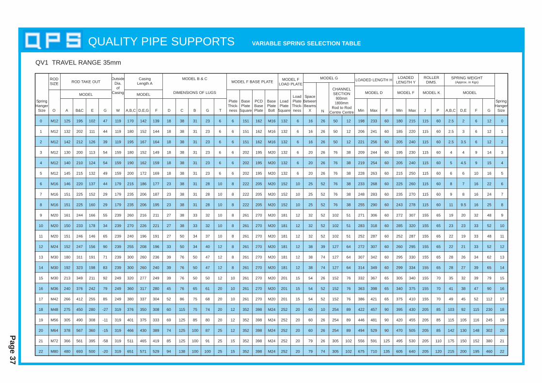
Page 37
QUALITY PIPE SUPPORTS VARIABLE SPRING SELECTION T ABLE
RODSIZE
OutsideDia.of
Casing
O A B&C E G W A,B,C D,E,G F D C B G T
PlateThick-ness
BasePlate
Square
PCDBasePlate
BasePlateBolt
SpringHanger
SizeMin MinMax MaxF F GJ P A,B,C D,E
LoadPlate
Square
LoadPlateThick-ness
SpaceBetweenBeams
X
CHANNELSECTION
900mm1800mm
Rod to RodCentre CentreN
MODEL MODEL
MODEL B & C
DIMENSIONS OF LUGS
MODEL F BASE PLATEMODEL G LOADED LENGTH H
MODEL D
LOADEDLENGTH Y
ROLLERDIMS.
MODEL F MODEL K MODEL
SPRING WEIGHT(Approx. in Kgs)
MODEL FLOAD PLATE
ROD TAKE OUTCasing
Length A
SpringHanger
Size
QV1 TRAVEL RANGE 35mm
132 6 16 26 50 12 198 233 60 180 215 115 60 2.5 2 6 12 0
132 6 16 26 50 12 206 241 60 185 220 115 60 2.5 3 6 12 1
132 6 16 26 50 12 221 256 60 205 240 115 60 2.5 3.5 6 12 2
132 6 20 26 76 38 209 244 60 195 230 115 60 4 4 9 14 3
132 6 20 26 76 38 219 254 60 205 240 115 60 5 4.5 9 15 4
132 6 20 26 76 38 228 263 60 215 250 115 60 6 6 10 16 5
152 10 25 52 76 38 233 268 60 225 260 115 60 8 7 16 22 6
152 10 25 52 76 38 248 283 60 235 270 115 60 9 8 16 24 7
152 10 25 52 76 38 255 290 60 243 278 115 60 11 9.5 16 25 8
181 12 32 52 102 51 271 306 60 272 307 155 65 19 20 32 48 9
181 12 32 52 102 51 283 318 60 285 320 155 65 23 23 33 52 10
181 12 32 52 102 51 252 287 60 252 287 155 65 22 19 33 48 11
181 12 38 39 127 64 272 307 60 260 295 155 65 22 21 33 52 12
181 12 38 74 127 64 307 342 60 295 330 155 65 28 26 34 62 13
181 12 38 74 127 64 314 349 60 299 334 155 65 28 27 39 65 14
201 15 54 26 152 76 332 367 65 305 340 155 70 35 32 39 79 15
201 15 54 52 152 76 363 398 65 340 375 155 70 41 38 47 90 16
201 15 54 52 152 76 386 421 65 375 410 155 70 49 45 52 112 17
252 20 60 10 254 89 422 457 90 395 430 205 85 103 92 115 230 18
252 20 60 26 254 89 446 481 90 420 455 205 85 115 105 116 245 19
252 20 60 26 254 89 494 529 90 470 505 205 85 142 130 148 302 20
252 20 79 26 305 102 556 591 125 495 530 205 110 175 150 152 380 21
252 20 79 74 305 102 675 710 135 605 640 205 120 215 200 195 460 22
0 M12 125 195 102 47 119 170 142 139 18 38 31 23 6 6 151 162 M16
1 M12 132 202 111 44 119 180 152 144 18 38 31 23 6 6 151 162 M16
2 M12 142 212 126 39 119 195 167 164 18 38 31 23 6 6 151 162 M16
3 M12 130 200 113 54 159 180 152 149 18 38 31 23 6 6 202 195 M20
4 M12 140 210 124 54 159 190 162 159 18 38 31 23 6 6 202 195 M20
5 M12 145 215 132 49 159 200 172 169 18 38 31 23 6 6 202 195 M20
6 M16 146 220 137 44 179 215 186 177 23 38 31 28 10 8 222 205 M20
7 M16 151 225 152 29 179 235 206 187 23 38 31 28 10 8 222 205 M20
8 M16 151 225 160 29 179 235 206 195 23 38 31 28 10 8 222 205 M20
9 M20 161 244 166 55 239 260 216 211 27 38 33 32 10 8 261 270 M20
10 M20 150 233 178 34 239 270 226 221 27 38 33 32 10 8 261 270 M20
11 M20 151 246 146 65 239 240 196 191 27 50 34 37 10 8 261 270 M20
12 M24 152 247 156 90 239 255 208 196 33 50 34 40 12 8 261 270 M20
13 M30 180 311 191 71 239 300 260 236 39 76 50 47 12 8 261 270 M20
14 M30 192 323 198 83 239 300 260 240 39 76 50 47 12 8 261 270 M20
15 M30 213 349 211 92 249 320 277 249 39 76 50 50 12 10 261 270 M20
16 M36 240 376 242 79 249 360 317 280 45 76 65 61 20 10 261 270 M20
17 M42 266 412 255 85 249 380 337 304 52 86 75 68 20 10 261 270 M20
18 M48 275 450 280 -27 319 376 350 308 60 115 75 74 20 12 352 398 M24
19 M56 305 490 308 -11 319 401 375 333 69 125 85 80 20 12 352 398 M24
20 M64 378 567 360 -15 319 466 430 389 74 125 100 87 25 12 352 398 M24
21 M72 366 561 395 -58 319 511 465 419 85 125 100 91 25 15 352 398 M24
22 M80 480 693 500 -20 319 651 571 529 94 138 100 100 25 15 352 398 M24
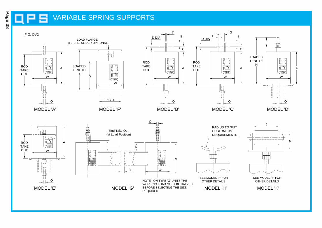
Page 38
O
W A
LOADEDLENGTH
’Y’
P.C.D.
W
MODEL ’D’MODEL ’C’
A
SEE MODEL ’F’ FOR
MODEL ’H’
OTHER DETAILS
RADIUS TO SUITCUSTOMERSREQUIREMENTS
MODEL ’K’
OTHER DETAILSSEE MODEL ’F’ FOR
P
J
RODTAKEOUT
AA
O O
W
D DIAB
T
C
G
Rod Take Out (at Load Position)
T B
C
LOADEDLENGTH
’H’A
W
O
FLOAD FLANGE
(P.T.F.E. SLIDER OPTIONAL)
MODEL ’B’
BEFORE SELECTING THE SIZEWORKING LOAD MUST BE HALVEDNOTE : ON TYPE ’G’ UNITS THE
O
W
D DIA
RODTAKEOUT
W
MODEL ’F’MODEL ’A’
MODEL ’E’
O
RODTAKEOUT
A
W
MODEL ’G’REQUIRED
X
N
ARODTAKEOUT
VARIABLE SPRING SUPPORTS
FIG. QV2
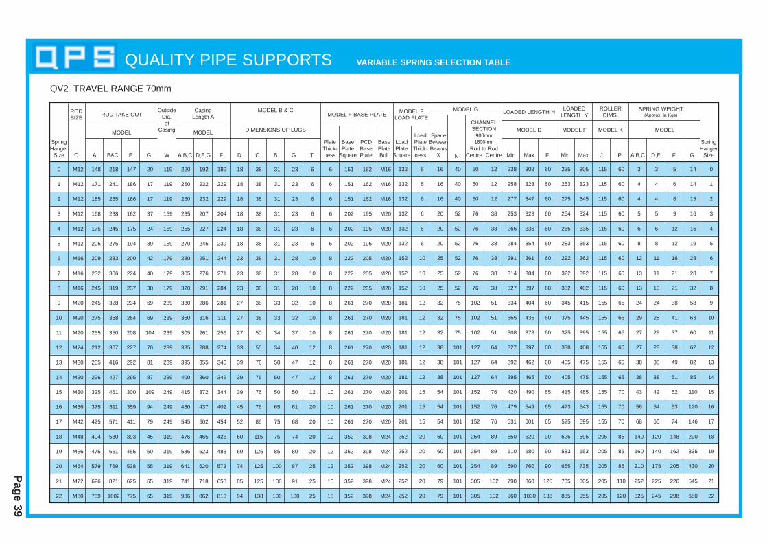
Page 39
QUALITY PIPE SUPPORTS VARIABLE SPRING SELECTION T ABLE
QV2 TRAVEL RANGE 70mm
RODSIZE
OutsideDia.of
Casing
O A B&C E G W A,B,C D,E,G F D C B G T
PlateThick-ness
BasePlate
Square
PCDBasePlate
BasePlateBolt
SpringHanger
SizeMin MinMax MaxF F GJ P A,B,C D,E
LoadPlate
Square
LoadPlateThick-ness
SpaceBetweenBeams
X
CHANNELSECTION
900mm1800mm
Rod to RodCentre CentreN
MODEL MODEL
MODEL B & C
DIMENSIONS OF LUGS
MODEL F BASE PLATEMODEL G LOADED LENGTH H
MODEL D
LOADEDLENGTH Y
ROLLERDIMS.
MODEL F MODEL K MODEL
SPRING WEIGHT(Approx. in Kgs)
MODEL FLOAD PLATE
ROD TAKE OUTCasing
Length A
SpringHanger
Size
0 M12 148 218 147 20 119 220 192 189 18 38 31 23 6 6 151 162 M16
1 M12 171 241 186 17 119 260 232 229 18 38 31 23 6 6 151 162 M16
2 M12 185 255 186 17 119 260 232 229 18 38 31 23 6 6 151 162 M16
3 M12 168 238 162 37 159 235 207 204 18 38 31 23 6 6 202 195 M20
4 M12 175 245 175 24 159 255 227 224 18 38 31 23 6 6 202 195 M20
5 M12 205 275 194 39 159 270 245 239 18 38 31 23 6 6 202 195 M20
6 M16 209 283 200 42 179 280 251 244 23 38 31 28 10 8 222 205 M20
7 M16 232 306 224 40 179 305 276 271 23 38 31 28 10 8 222 205 M20
8 M16 245 319 237 38 179 320 291 284 23 38 31 28 10 8 222 205 M20
9 M20 245 328 234 69 239 330 286 281 27 38 33 32 10 8 261 270 M20
10 M20 275 358 264 69 239 360 316 311 27 38 33 32 10 8 261 270 M20
11 M20 255 350 208 104 239 305 261 256 27 50 34 37 10 8 261 270 M20
12 M24 212 307 227 70 239 335 288 274 33 50 34 40 12 8 261 270 M20
13 M30 285 416 292 81 239 395 355 346 39 76 50 47 12 8 261 270 M20
14 M30 296 427 295 87 239 400 360 346 39 76 50 47 12 8 261 270 M20
15 M30 325 461 300 109 249 415 372 344 39 76 50 50 12 10 261 270 M20
16 M36 375 511 359 94 249 480 437 402 45 76 65 61 20 10 261 270 M20
17 M42 425 571 411 79 249 545 502 454 52 86 75 68 20 10 261 270 M20
18 M48 404 580 393 45 319 476 465 428 60 115 75 74 20 12 352 398 M24
19 M56 475 661 455 50 319 536 523 483 69 125 85 80 20 12 352 398 M24
20 M64 579 769 538 55 319 641 620 573 74 125 100 87 25 12 352 398 M24
21 M72 626 821 625 65 319 741 718 650 85 125 100 91 25 15 352 398 M24
22 M80 789 1002 775 65 319 936 862 810 94 138 100 100 25 15 352 398 M24
132 6 16 40 50 12 238 308 60 235 305 115 60 3 3 5 14 0
132 6 16 40 50 12 258 328 60 253 323 115 60 4 4 6 14 1
132 6 16 40 50 12 277 347 60 275 345 115 60 4 4 8 15 2
132 6 20 52 76 38 253 323 60 254 324 115 60 5 5 9 16 3
132 6 20 52 76 38 266 336 60 265 335 115 60 6 6 12 16 4
132 6 20 52 76 38 284 354 60 283 353 115 60 8 8 12 19 5
152 10 25 52 76 38 291 361 60 292 362 115 60 12 11 16 28 6
152 10 25 52 76 38 314 384 60 322 392 115 60 13 11 21 28 7
152 10 25 52 76 38 327 397 60 332 402 115 60 13 13 21 32 8
181 12 32 75 102 51 334 404 60 345 415 155 65 24 24 38 58 9
181 12 32 75 102 51 365 435 60 375 445 155 65 29 28 41 63 10
181 12 32 75 102 51 308 378 60 325 395 155 65 27 29 37 60 11
181 12 38 101 127 64 327 397 60 338 408 155 65 27 28 38 62 12
181 12 38 101 127 64 392 462 60 405 475 155 65 38 35 49 82 13
181 12 38 101 127 64 395 465 60 405 475 155 65 38 38 51 85 14
201 15 54 101 152 76 420 490 65 415 485 155 70 43 42 52 110 15
201 15 54 101 152 76 479 549 65 473 543 155 70 56 54 63 120 16
201 15 54 101 152 76 531 601 65 525 595 155 70 68 65 74 146 17
252 20 60 101 254 89 550 620 90 525 595 205 85 140 120 148 290 18
252 20 60 101 254 89 610 680 90 583 653 205 85 160 140 162 335 19
252 20 60 101 254 89 690 760 90 665 735 205 85 210 175 205 430 20
252 20 79 101 305 102 790 860 125 735 805 205 110 252 225 226 545 21
252 20 79 101 305 102 960 1030 135 885 955 205 120 325 245 298 680 22
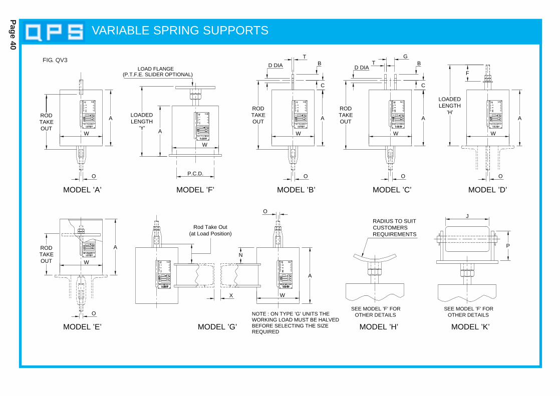
O
W A
LOADEDLENGTH
’Y’
P.C.D.
W
MODEL ’D’MODEL ’C’
A
SEE MODEL ’F’ FOR
MODEL ’H’
OTHER DETAILS
RADIUS TO SUITCUSTOMERSREQUIREMENTS
MODEL ’K’
OTHER DETAILSSEE MODEL ’F’ FOR
P
J
RODTAKEOUT
AA
O O
W
D DIAB
T
C
G
Rod Take Out (at Load Position)
T B
C
LOADEDLENGTH
’H’A
W
O
FLOAD FLANGE
(P.T.F.E. SLIDER OPTIONAL)
MODEL ’B’
BEFORE SELECTING THE SIZEWORKING LOAD MUST BE HALVEDNOTE : ON TYPE ’G’ UNITS THE
O
W
D DIA
RODTAKEOUT
W
MODEL ’F’MODEL ’A’
MODEL ’E’
O
RODTAKEOUT
A
W
MODEL ’G’REQUIRED
X
N
ARODTAKEOUT
Page 40
VARIABLE SPRING SUPPORTS
FIG. QV3
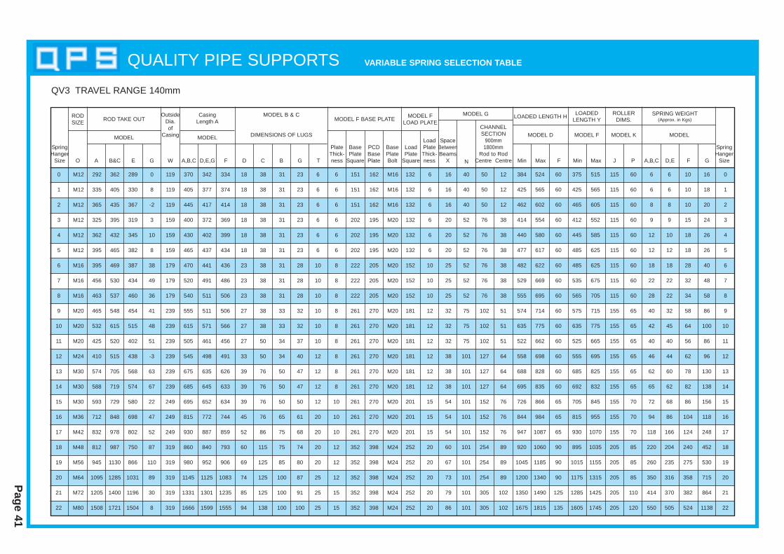
Page 41
QUALITY PIPE SUPPORTS VARIABLE SPRING SELECTION T ABLE
QV3 TRAVEL RANGE 140mm
RODSIZE
OutsideDia.of
Casing
O A B&C E G W A,B,C D,E,G F D C B G T
PlateThick-ness
BasePlate
Square
PCDBasePlate
BasePlateBolt
SpringHanger
SizeMin MinMax MaxF F GJ P A,B,C D,E
LoadPlate
Square
LoadPlateThick-ness
SpaceBetweenBeams
X
CHANNELSECTION
900mm1800mm
Rod to RodCentre CentreN
MODEL MODEL
MODEL B & C
DIMENSIONS OF LUGS
MODEL F BASE PLATEMODEL G LOADED LENGTH H
MODEL D
LOADEDLENGTH Y
ROLLERDIMS.
MODEL F MODEL K MODEL
SPRING WEIGHT(Approx. in Kgs)
MODEL FLOAD PLATE
ROD TAKE OUTCasing
Length A
SpringHanger
Size
0 M12 292 362 289 0 119 370 342 334 18 38 31 23 6 6 151 162 M16
1 M12 335 405 330 8 119 405 377 374 18 38 31 23 6 6 151 162 M16
2 M12 365 435 367 -2 119 445 417 414 18 38 31 23 6 6 151 162 M16
3 M12 325 395 319 3 159 400 372 369 18 38 31 23 6 6 202 195 M20
4 M12 362 432 345 10 159 430 402 399 18 38 31 23 6 6 202 195 M20
5 M12 395 465 382 8 159 465 437 434 18 38 31 23 6 6 202 195 M20
6 M16 395 469 387 38 179 470 441 436 23 38 31 28 10 8 222 205 M20
7 M16 456 530 434 49 179 520 491 486 23 38 31 28 10 8 222 205 M20
8 M16 463 537 460 36 179 540 511 506 23 38 31 28 10 8 222 205 M20
9 M20 465 548 454 41 239 555 511 506 27 38 33 32 10 8 261 270 M20
10 M20 532 615 515 48 239 615 571 566 27 38 33 32 10 8 261 270 M20
11 M20 425 520 402 51 239 505 461 456 27 50 34 37 10 8 261 270 M20
12 M24 410 515 438 -3 239 545 498 491 33 50 34 40 12 8 261 270 M20
13 M30 574 705 568 63 239 675 635 626 39 76 50 47 12 8 261 270 M20
14 M30 588 719 574 67 239 685 645 633 39 76 50 47 12 8 261 270 M20
15 M30 593 729 580 22 249 695 652 634 39 76 50 50 12 10 261 270 M20
16 M36 712 848 698 47 249 815 772 744 45 76 65 61 20 10 261 270 M20
17 M42 832 978 802 52 249 930 887 859 52 86 75 68 20 10 261 270 M20
18 M48 812 987 750 87 319 860 840 793 60 115 75 74 20 12 352 398 M24
19 M56 945 1130 866 110 319 980 952 906 69 125 85 80 20 12 352 398 M24
20 M64 1095 1285 1031 89 319 1145 1125 1083 74 125 100 87 25 12 352 398 M24
21 M72 1205 1400 1196 30 319 1331 1301 1235 85 125 100 91 25 15 352 398 M24
22 M80 1508 1721 1504 8 319 1666 1599 1555 94 138 100 100 25 15 352 398 M24
132 6 16 40 50 12 384 524 60 375 515 115 60 6 6 10 16 0
132 6 16 40 50 12 425 565 60 425 565 115 60 6 6 10 18 1
132 6 16 40 50 12 462 602 60 465 605 115 60 8 8 10 20 2
132 6 20 52 76 38 414 554 60 412 552 115 60 9 9 15 24 3
132 6 20 52 76 38 440 580 60 445 585 115 60 12 10 18 26 4
132 6 20 52 76 38 477 617 60 485 625 115 60 12 12 18 26 5
152 10 25 52 76 38 482 622 60 485 625 115 60 18 18 28 40 6
152 10 25 52 76 38 529 669 60 535 675 115 60 22 22 32 48 7
152 10 25 52 76 38 555 695 60 565 705 115 60 28 22 34 58 8
181 12 32 75 102 51 574 714 60 575 715 155 65 40 32 58 86 9
181 12 32 75 102 51 635 775 60 635 775 155 65 42 45 64 100 10
181 12 32 75 102 51 522 662 60 525 665 155 65 40 40 56 86 11
181 12 38 101 127 64 558 698 60 555 695 155 65 46 44 62 96 12
181 12 38 101 127 64 688 828 60 685 825 155 65 62 60 78 130 13
181 12 38 101 127 64 695 835 60 692 832 155 65 65 62 82 138 14
201 15 54 101 152 76 726 866 65 705 845 155 70 72 68 86 156 15
201 15 54 101 152 76 844 984 65 815 955 155 70 94 86 104 118 16
201 15 54 101 152 76 947 1087 65 930 1070 155 70 118 166 124 248 17
252 20 60 101 254 89 920 1060 90 895 1035 205 85 220 204 240 452 18
252 20 67 101 254 89 1045 1185 90 1015 1155 205 85 260 235 275 530 19
252 20 73 101 254 89 1200 1340 90 1175 1315 205 85 350 316 358 715 20
252 20 79 101 305 102 1350 1490 125 1285 1425 205 110 414 370 382 864 21
252 20 86 101 305 102 1675 1815 135 1605 1745 205 120 550 505 524 1138 22

O
W A
LOADEDLENGTH
’Y’
P.C.D.
W
MODEL ’D’MODEL ’C’
A
SEE MODEL ’F’ FOR
MODEL ’H’
OTHER DETAILS
RADIUS TO SUITCUSTOMERSREQUIREMENTS
MODEL ’K’
OTHER DETAILSSEE MODEL ’F’ FOR
P
J
RODTAKEOUT
AA
O O
W
D DIAB
T
C
G
Rod Take Out (at Load Position)
T B
C
LOADEDLENGTH
’H’A
W
O
FLOAD FLANGE
(P.T.F.E. SLIDER OPTIONAL)
MODEL ’B’
BEFORE SELECTING THE SIZEWORKING LOAD MUST BE HALVEDNOTE : ON TYPE ’G’ UNITS THE
O
W
D DIA
RODTAKEOUT
W
MODEL ’F’MODEL ’A’
MODEL ’E’
O
RODTAKEOUT
A
W
MODEL ’G’REQUIRED
X
N
ARODTAKEOUT
Page 42
VARIABLE SPRING SUPPORTS
FIG. QV4

Page 43
QUALITY PIPE SUPPORTS VARIABLE SPRING SELECTION T ABLE
QV4 TRAVEL RANGE 210mm
RODSIZE
OutsideDia.of
Casing
O A B&C E G W A,B,C D,E,G F D C B G T
PlateThick-ness
BasePlate
Square
PCDBasePlate
BasePlateBolt
SpringHanger
SizeMin MinMax MaxF F GJ P A,B,C D,E
LoadPlate
Square
LoadPlateThick-ness
SpaceBetweenBeams
X
CHANNELSECTION
900mm1800mm
Rod to RodCentre CentreN
MODEL MODEL
MODEL B & C
DIMENSIONS OF LUGS
MODEL F BASE PLATEMODEL G LOADED LENGTH H
MODEL D
LOADEDLENGTH Y
ROLLERDIMS.
MODEL F MODEL K MODEL
SPRING WEIGHT(Approx. in Kgs)
MODEL FLOAD PLATE
ROD TAKE OUTCasing
Length A
SpringHanger
Size
0 M12 452 522 440 50 119 530 495 485 18 38 31 23 6 6 151 162 M16
1 M12 510 580 490 50 119 580 545 535 18 38 31 23 6 6 151 162 M16
2 M12 555 625 545 50 119 635 605 595 18 38 31 23 6 6 151 162 M16
3 M12 490 560 475 60 159 565 535 520 18 38 31 23 6 6 202 195 M20
4 M12 547 617 525 60 159 615 580 570 18 38 31 23 6 6 202 195 M20
5 M12 595 665 575 60 159 665 635 625 18 38 31 23 6 6 202 195 M20
6 M16 595 669 575 60 179 670 640 625 23 38 31 28 10 8 222 205 M20
7 M16 676 750 645 60 179 740 710 695 23 38 31 28 10 8 222 205 M20
8 M16 698 772 680 60 179 775 745 730 23 38 31 28 10 8 222 205 M20
9 M20 695 778 670 90 239 785 750 725 27 38 33 32 10 8 261 270 M20
10 M20 797 880 770 90 239 880 845 825 27 38 33 32 10 8 261 270 M20
11 M20 630 725 600 90 239 710 680 655 27 50 34 37 10 8 261 270 M20
12 M24 640 745 650 110 239 775 735 715 33 50 34 40 12 8 261 270 M20
13 M30 874 1005 845 110 239 975 930 905 39 76 50 47 12 8 261 270 M20
14 M30 883 1014 855 110 239 980 940 920 39 76 50 47 12 8 261 270 M20
15 M30 888 1024 860 110 249 990 960 930 39 76 50 50 12 10 261 270 M20
16 M36 1072 1208 1040 110 249 1175 1140 1105 45 76 65 61 20 10 261 270 M20
17 M42 1237 1383 1195 110 249 1335 1305 1265 52 86 75 68 20 10 261 270 M20
18 M48 1182 1357 1110 110 319 1230 1230 1160 60 115 75 74 20 12 352 398 M24
19 M56 1380 1555 1290 110 319 1405 1395 1330 69 125 85 80 20 12 352 398 M24
20 M64 1610 1800 1540 110 319 1660 1660 1590 74 125 100 87 25 12 352 398 M24
21 M72 1790 1985 1780 110 319 1910 1910 1825 85 125 100 91 25 15 352 398 M24
22 M80 2258 2471 2245 110 319 2410 2395 2285 94 138 100 100 25 15 352 398 M24
132 6 16 40 50 12 550 760 54 560 770 115 60 7 7 12 19 0
132 6 16 40 50 12 610 820 54 620 830 115 60 10 10 13 26 1
132 6 16 40 50 12 660 870 54 680 890 115 60 10 10 13 26 2
132 6 20 50 76 38 590 800 54 610 820 115 60 13 13 21 30 3
132 6 20 50 76 38 640 850 54 655 865 115 60 16 15 24 37 4
132 6 20 50 76 38 695 905 54 710 920 115 60 17 17 25 35 5
152 10 25 50 76 38 690 900 54 710 920 115 60 27 25 37 55 6
152 10 25 50 76 38 760 970 54 785 995 115 60 31 29 45 67 7
152 10 25 50 76 38 795 1005 54 820 1030 115 60 42 40 48 88 8
181 12 32 75 102 51 810 1020 54 830 1040 155 65 57 57 80 119 9
181 12 32 75 102 51 910 1120 54 920 1130 155 65 69 67 87 136 10
181 12 32 75 102 51 740 950 54 760 970 155 65 55 50 75 114 11
181 12 38 100 127 64 790 1000 54 805 1015 155 65 62 61 83 132 12
181 12 38 100 127 64 990 1200 54 1000 1210 155 65 85 83 107 179 13
181 12 38 100 127 64 1000 1210 54 1010 1220 155 65 90 88 115 197 14
201 15 54 100 152 76 1020 1230 70 1015 1225 155 70 103 99 118 205 15
201 15 54 100 152 76 1200 1410 70 1190 1400 155 70 136 132 149 315 16
201 15 54 100 152 76 1360 1570 70 1350 1560 155 70 170 155 174 344 17
252 20 60 100 254 89 1315 1525 84 1285 1495 205 85 302 287 336 618 18
252 20 67 100 254 89 1485 1695 84 1442 1652 205 85 370 336 385 738 19
252 20 73 100 254 89 1735 1945 84 1705 1915 205 85 501 465 510 1010 20
252 20 79 100 305 102 1935 2145 115 1885 2095 205 110 570 530 540 1180 21
252 20 86 100 305 102 2415 2625 131 2340 2550 205 120 775 769 755 1602 22

Page 44
INSTALLATION INSTRUCTIONS
QUALITY PIPE SUPPORTS
VARIABLE SPRING UNITSVariable Spring Units are pre-set to a cold load position before despatch from our works.
The pipe system being supported in service would be either :(a) dry system(b) wet system
In the event that the system is 'dry' in service but has to undergo a hydraulic test prior toservice the spring units should be ordered with down travel hydrostatic test stops whichwould remain in position until the hydraulic test has been carried out.In the event that the system is 'wet' in service then the standard pre-set stops which set theunits to 'wet load' are all that is necessary.Once removed the pre-set stops on all units should be retained in case of a requirement for futureuse. If it becomes obvious that an incorrect load is being applied to any supports in the system itis advisable to contact our sales support team who would be pleased to give advice.
To Install Spring Units - Type A,B,C.The spring unit is fitted between the Pipe/Duct/Bracket to be supported and the steelworkabove the unit. The hanger rod coming up from the Pipe Clamp/Duct/Bracket is connected tothe turnbuckle which is fitted to all these types of spring units.Rotation of the turnbuckle transfers the pipe load to the spring unit thus allowing withdrawalof the pre-set stops. No further adjustment should be required unless it becomes obvious thatincorrect loads are being applied to supports in the system.
To Install Units Type D and E.Both of these units are mounted on top of the steelwork.
Type DThe hanger rod passes through the unit and is secured to the spring unit at the top of the loadtube by 2 nuts. The hanger rod should be of adequate length and threaded sufficiently to takeinto account any deviation in pipe or duct elevation since these units are not supplied with aturnbuckle. Adjustment of the 2 nuts transfers the load to the spring unit thus allowingwithdrawal of the pre- set stops.
Type EThe hanger rod passes through the Spring units and is secured with 2 nuts which prevent itpassing through the Spring pressure plate. Adjustment in length is provided by a turnbuckleat a convenient situation in the hanger assembly.Rotation of the turnbuckle transfers the load to the spring unit allowing withdrawal of the pre-set stops.
To Install Spring Units Type F, H & KThese units are base mounted and should be aligned directly below the point of support. Theheight of the load flange is adjusted to contact the lower surface of the support point byrotation of the adjustment nut on the load column. Further rotation of this nut will transfer theload onto the Spring unit and the pre-set stops can then be withdrawn.
INSTALLATION INSTRUCTIONS
Page 45
To Install Spring Units Type F(A)These units are base mounted and should be aligned directly below the point of support. Theheight of the load flange is adjusted to contact the lower surface of the support point byrotation of the adjustment nut on the load column. The lower of the two sets of "Red Painted"adjusting nuts(A) can be wound clear of the pressure plate at this time, or after the HydrostaticTest (if required) has taken place. Further rotation of the adjustment nut on the load columnwill transfer the load onto the spring unit. The upper of the two sets of "Red Painted" adjustingnuts (B) can then be wound clear of the pressure plate.eg.(towards the locknut(C)).
To Install Spring Units Type GThe units are fitted with turnbuckles so that the hanger rods which having been previouslyconnected to the steelwork above can be inserted into them. The rotation of the turnbucklestransfers the load to the spring units. When the load is correctly supported the pre-set stopscan be withdrawn.
Inspection During OperationShortly after commissioning the support should be examined to ensure correct travel hasbeen achieved in the hot position. If the load plate is against the stop at either end of the scalean investigation should be made at once. Subsequently the support should be examined atregular intervals to ensure no change has occurred either in application or condition. Thefrequency of examination intervals will depend on the environmental and operatingconditions and will range from annual examinations for land based dry atmospheres tomaybe monthly frequency in hostile offshore conditions with the possibility of saltcontamination.
MaintenanceIf an excessive build up of foreign matter or corrosion is observed it is important that theSpring support is cleaned either by hand or with a pressure washer to ensure uninhibitedoperation.
INSTALLATION INSTRUCTIONS

Page 46
NOTES

AncillaryEquipment
Section 3
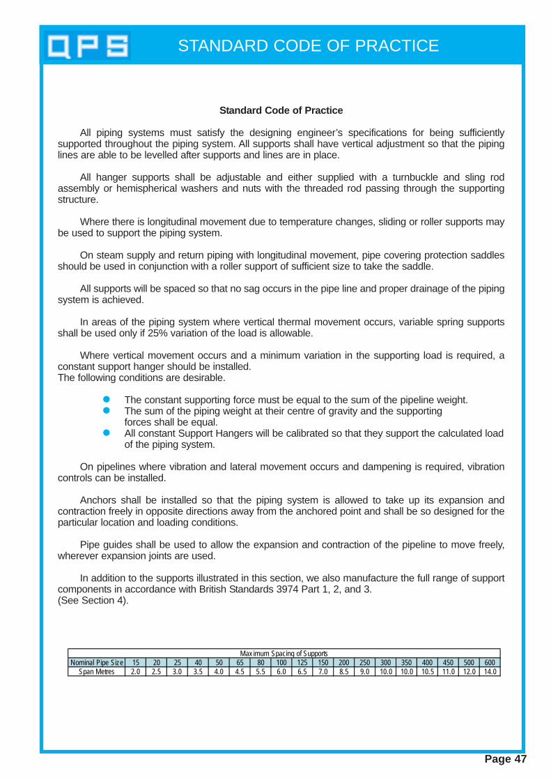
STANDARD CODE OF PRACTICE
Nominal Pipe Size 15 20 25 40 50 65 80 100 125 150 200 250 300 350 400 450 500 600Span Metres 2.0 2.5 3.0 3.5 4.0 4.5 5.5 6.0 6.5 7.0 8.5 9.0 10.0 10.0 10.5 11.0 12.0 14.0
Max imum Spacing of Supports
Page 47
Standard Code of Practice
All piping systems must satisfy the designing engineer’s specifications for being sufficientlysupported throughout the piping system. All supports shall have vertical adjustment so that the pipinglines are able to be levelled after supports and lines are in place.
All hanger supports shall be adjustable and either supplied with a turnbuckle and sling rodassembly or hemispherical washers and nuts with the threaded rod passing through the supportingstructure.
Where there is longitudinal movement due to temperature changes, sliding or roller supports maybe used to support the piping system.
On steam supply and return piping with longitudinal movement, pipe covering protection saddlesshould be used in conjunction with a roller support of sufficient size to take the saddle.
All supports will be spaced so that no sag occurs in the pipe line and proper drainage of the pipingsystem is achieved.
In areas of the piping system where vertical thermal movement occurs, variable spring supportsshall be used only if 25% variation of the load is allowable.
Where vertical movement occurs and a minimum variation in the supporting load is required, aconstant support hanger should be installed.The following conditions are desirable.
l The constant supporting force must be equal to the sum of the pipeline weight.l The sum of the piping weight at their centre of gravity and the supporting
forces shall be equal.l All constant Support Hangers will be calibrated so that they support the calculated load
of the piping system.
On pipelines where vibration and lateral movement occurs and dampening is required, vibrationcontrols can be installed.
Anchors shall be installed so that the piping system is allowed to take up its expansion andcontraction freely in opposite directions away from the anchored point and shall be so designed for theparticular location and loading conditions.
Pipe guides shall be used to allow the expansion and contraction of the pipeline to move freely,wherever expansion joints are used.
In addition to the supports illustrated in this section, we also manufacture the full range of supportcomponents in accordance with British Standards 3974 Part 1, 2, and 3.(See Section 4).
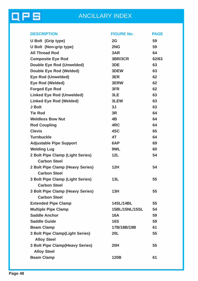
ANCILLARY INDEX
Page 48
U Bolt (Grip type)
U Bolt (Non-grip type)
All Thread Rod
Composite Eye Rod
Double Eye Rod (Unwelded)
Double Eye Rod (Welded)
Eye Rod (Unwelded)
Eye Rod (Welded)
Forged Eye Rod
Linked Eye Rod (Unwelded)
Linked Eye Rod (Welded)
J Bolt
Tie Rod
Weldless Bow Nut
Rod Coupling
Clevis
Turnbuckle
Adjustable Pipe Support
Welding Lug
2 Bolt Pipe Clamp (Light Series)
Carbon Steel
2 Bolt Pipe Clamp (Heavy Series)
Carbon Steel
3 Bolt Pipe Clamp (Light Series)
Carbon Steel
3 Bolt Pipe Clamp (Heavy Series)
Carbon Steel
Extended Pipe Clamp
Multiple Pipe Clamp
Saddle Anchor
Saddle Guide
Beam Clamp
3 Bolt Pipe Clamp(Light Series)
Alloy Steel
3 Bolt Pipe Clamp(Heavy Series)
Alloy Steel
Beam Clamp
2G
2NG
3AR
3BR/3CR
3DE
3DEW
3ER
3ERW
3FR
3LE
3LEW
3J
3R
4B
4RC
4SC
4T
6AP
9WL
12L
12H
13L
13H
14SL/14BL
15BL/15NL/15SL
16A
16S
17B/18B/19B
20L
20H
120B
59
59
64
62/63
63
63
62
62
62
63
63
63
64
64
64
65
64
69
60
54
54
55
55
55
54
59
59
61
55
55
61
DESCRIPTION FIGURE No. PAGE
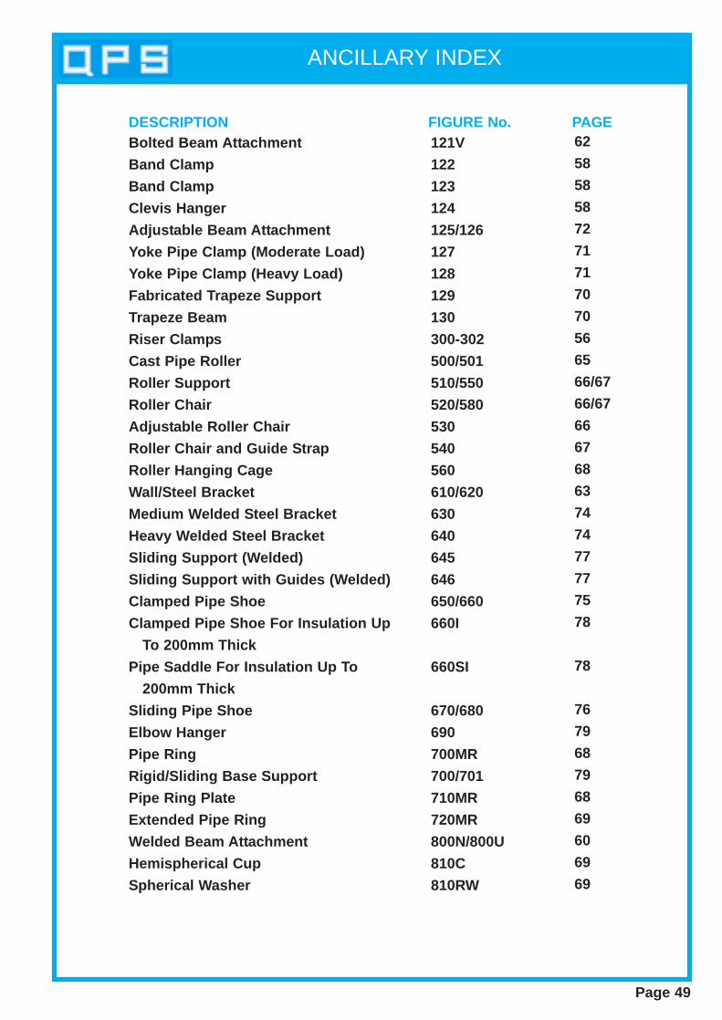
ANCILLARY INDEX
Page 49
Bolted Beam Attachment
Band Clamp
Band Clamp
Clevis Hanger
Adjust able Beam Att achment
Yoke Pipe Clamp (Moderate Load)
Yoke Pipe Clamp (Heavy Load)
Fabricated T rapeze Support
Trapeze Beam
Riser Clamp s
Cast Pipe Roller
Roller Support
Roller Chair
Adjust able Roller Chair
Roller Chair and Guide S trap
Roller Hanging Cage
Wall/Steel Bracket
Medium W elded S teel Bracket
Heavy Welded S teel Bracket
Sliding Support (W elded)
Sliding Support with Guides (W elded)
Clamped Pipe Shoe
Clamped Pipe Shoe For Insulation Up
To 200mm Thick
Pipe Saddle For Insulation Up T o
200mm Thick
Sliding Pipe Shoe
Elbow Hanger
Pipe Ring
Rigid/Sliding Base Support
Pipe Ring Plate
Extended Pipe Ring
Welded Beam Att achment
Hemispherical Cup
Spherical W asher
121V
122
123
124
125/126
127
128
129
130
300-302
500/501
510/550
520/580
530
540
560
610/620
630
640
645
646
650/660
660I
660SI
670/680
690
700MR
700/701
710MR
720MR
800N/800U
810C
810RW
62
58
58
58
72
71
71
70
70
56
65
66/67
66/67
66
67
68
63
74
74
77
77
75
78
78
76
79
68
79
68
69
60
69
69
DESCRIPTION FIGURE No. PAGE
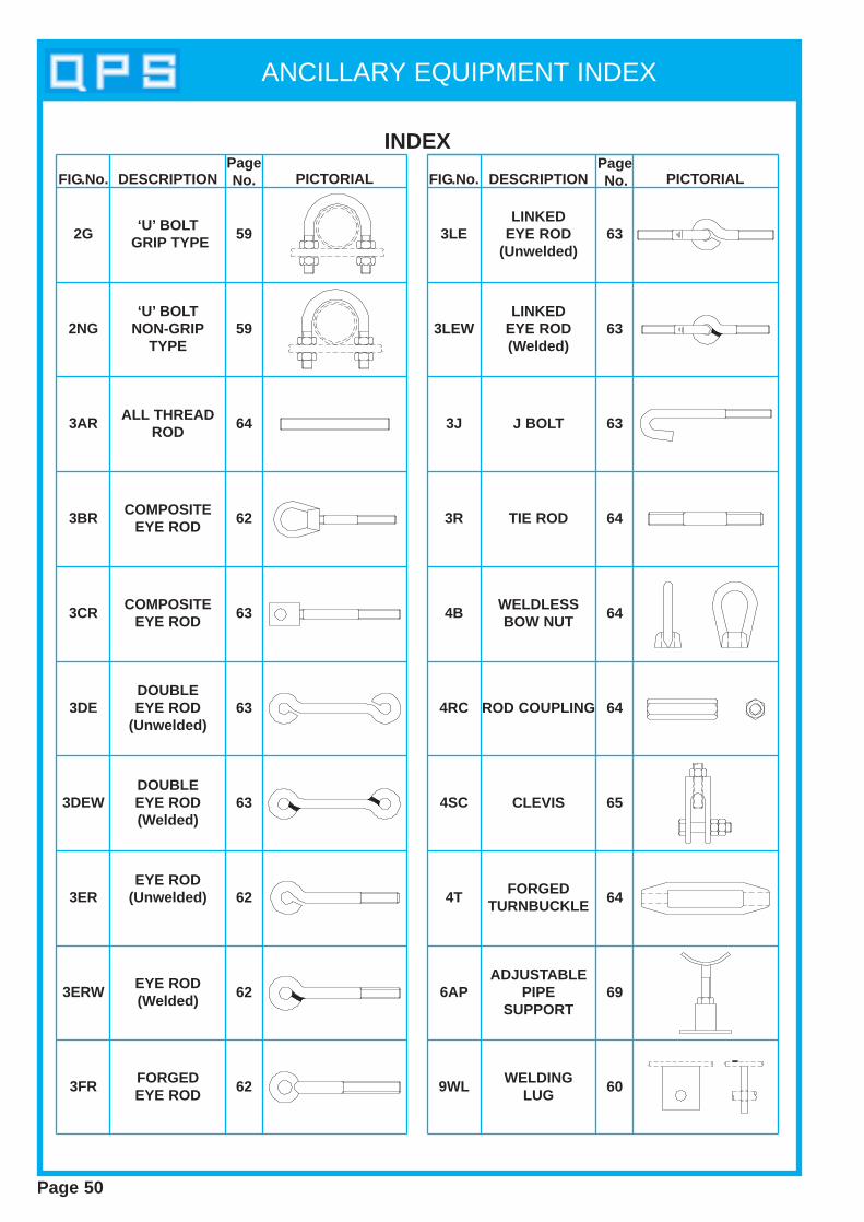
ANCILLARY EQUIPMENT INDEX
Page 50
INDEX
FIG.No. DESCRIPTIONPageNo. PICTORIAL FIG.No. DESCRIPTION
PageNo. PICTORIAL
2G
2NG
3AR
3BR
3CR
3DE
3DEW
3ER
3ERW
3FR
3LE
3LEW
3J
3R
4B
4RC
4SC
4T
6AP
9WL
‘U’ BOLTGRIP TYPE
‘U’ BOLTNON-GRIP
TYPE
ALL THREADROD
COMPOSITEEYE ROD
COMPOSITEEYE ROD
DOUBLEEYE ROD
(Unwelded)
DOUBLEEYE ROD(Welded)
EYE ROD(Unwelded)
EYE ROD(Welded)
FORGEDEYE ROD
LINKEDEYE ROD
(Unwelded)
LINKEDEYE ROD(Welded)
J BOLT
TIE ROD
WELDLESSBOW NUT
ROD COUPLING
CLEVIS
FORGEDTURNBUCKLE
ADJUSTABLEPIPE
SUPPORT
WELDINGLUG
59
59
64
62
63
63
63
62
62
62
63
63
63
64
64
64
65
64
69
60

ANCILLARY EQUIPMENT INDEX
INDEX
FIG.No. DESCRIPTIONPageNo. PICTORIAL FIG.No. DESCRIPTION
PageNo. PICTORIAL
12L
12H
13L
13H
14BL
14SL
15BL
15NL
15SL
16A
16S
17B
18B
19B
20L
20H
120B
121V
122
123
2 BOLT PIPECLAMP
LIGHT SERIES(Carbon S teel)
2 BOLT PIPECLAMP
HEAVY SERIES(Carbon S teel)
3 BOLT PIPECLAMP
LIGHT SERIES(Carbon S teel)
3 BOLT PIPECLAMP
HEAVY SERIES(Carbon S teel)
EXTENDEDPIPE CLAMP(Bent Legs)
EXTENDEDPIPE CLAMP
(Straight Legs)
MULTIPLEPIPE CLAMP(Bent Legs)
MULTIPLEPIPE CLAMPS
(No Legs)
MULTIPLEPIPE CLAMP
(Straight Legs)
SADDLEANCHOR
SADDLEGUIDE
BEAMCLAMP
BEAMCLAMP
BEAMCLAMP
3 BOLT PIPECLAMP
LIGHT SERIES(Alloy S teel)
3 BOLT PIPECLAMP
HEAVY SERIES(Alloy S teel)
BEAMCLAMP
BOLTEDBEAM
ATTACHMENT
BANDCLAMP
BANDCLAMP
54
54
55
55
55
55
54
54
54
59
59
61
61
61
55
55
61
62
58
58
Page 51

ANCILLARY EQUIPMENT INDEX
INDEX
FIG.No. DESCRIPTIONPageNo. PICTORIAL FIG.No. DESCRIPTION
PageNo. PICTORIAL
124 500
501
510
520
530
550
560
580
125
CLEVISHANGER
CASTPIPE
ROLLER
CASTPIPE
ROLLER
ROLLERSUPPORT
ROLLERCHAIR
ADJUSTABLEROLLERCHAIR
ROLLERSUPPORT
ROLLERHANGING
CAGE
ROLLERCHAIR
ADJUSTABLEBEAM
ATTACHMENT
58
65
66
66
66
67
68
67
72
126
127
ADJUSTABLEBEAM
ATTACHMENT
YOKEPIPE CLAMP
(Moderate Load)
72
71
540
ROLLERCHAIR &GUIDE STRAP
67
128YOKE
PIPE CLAMP(Heavy Load)
129FABRICATED
TRAPEZESUPPORT
70
130TRAPEZE
BEAM
610WALL/STEEL
BRACKET73
71
70
65
Page 52
300
301
302
4 BOLTRISERCLAMP
6 BOLTRISERCLAMP
10 BOLTRISERCLAMP
56
56
56

ANCILLARY EQUIPMENT INDEX
INDEX
FIG.No. DESCRIPTIONPageNo. PICTORIAL FIG.No. DESCRIPTION
PageNo. PICTORIAL
650
660
670
680
CLAMPEDPIPE SHOE
CLAMPEDPIPE SHOE
SLIDINGPIPE SHOE
SLIDINGPIPE SHOE
690ELBOW
HANGER
700/701
RIGID/SLIDINGBASE SUPPORT
75
75
76
76
79
79
800U
810RW
WELDEDBEAM
ATTACHMENT
HEMISPHERICALCUP
HEMISPHERICALWASHER
60
69
69
810C
700MR
710MR
720MR
800N
PIPERING
PIPERING
PLATE
EXTENDEDPIPERING
WELDEDBEAM
ATTACHMENT
68
68
69
60
Page 53
645SLIDING
SUPPORT(Welded)
77
660I
CLAMPEDPIPE SHOE FORINSULATION UP
TO 200mm
78
660SI
PIPE SADDLEFOR
INSULATIONUP TO 200mm
78
646
SLIDINGSUPPORT
WITH GUIDES(Welded)
77
620
630
WALL/STEELBRACKET
MEDIUMWELDED STEEL
BRACKET
73
74
640HEAVY
WELDED STEELBRACKET
74
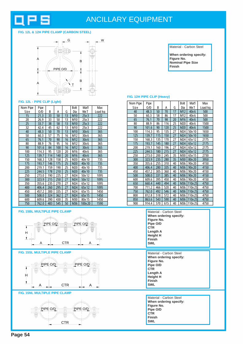
ANCILLARY EQUIPMENT
Page 54
Nom Pipe Pipe Bolt Mat'l MaxSize O/D B A G Dia Wx T Load kg15 21.3 33 50 13 M10 25x 3 22220 26.9 33 50 13 M10 25x 3 22225 33.7 38 58 13 M10 25x 3 22232 42.4 45 62 13 M10 25x 3 22240 48.3 50 70 13 M10 30x 6 36550 60.3 57 75 16 M12 30x 6 36565 76.1 70 90 16 M12 30x 6 36580 88.9 76 95 16 M12 30x 6 36590 101.6 84 100 16 M12 30x 6 365
100 114.3 95 120 20 M16 40x 6 365125 139.7 114 140 20 M16 40x 6 365150 168.3 128 158 25 M20 40x 10 735175 193.7 146 175 25 M20 40x 10 735200 219.1 159 190 25 M20 40x 10 735225 244.5 178 210 25 M20 40x 10 735250 273.0 190 225 27 M24 50x 12 1095300 323.9 215 250 27 M24 50x 12 1095350 355.6 235 270 27 M24 65x 12 1095400 406.4 260 295 27 M24 65x 12 1095450 457.2 300 335 27 M24 65x 15 1450500 508.0 324 362 27 M24 65x 15 1450600 609.6 390 430 35 M30 80x 15 1450750 762.0 483 545 50 M36 100x 20 1590
Nom Pipe Pipe Bolt Mat'l MaxSize O/D B A G Dia Wx T Load kg40 48.3 50 70 17 M12 40x 6 50050 60.3 58 86 17 M12 40x 6 50065 76.1 70 98 20 M16 40x 6 50080 88.9 86 116 25 M20 40x 6 150090 101.6 90 120 25 M20 40x 6 1500100 114.3 95 135 27 M24 50x 10 1650125 139.7 115 150 27 M24 50x 10 1650150 168.3 135 170 27 M24 65x 12 2175175 193.7 145 180 27 M24 65x 12 2175200 219.1 160 196 27 M24 65x 12 2175225 244.5 180 215 27 M24 65x 12 2175250 273.0 200 245 35 M30 65x 15 2730300 323.9 235 280 35 M30 80x 20 3950350 355.6 255 310 40 M36 90x 20 4150400 406.4 280 335 40 M36 90x 20 4150450 457.2 305 360 40 M36 90x 20 4150500 508.0 331 385 40 M36 90x 20 4150600 609.6 395 450 40 M36 90x 20 4150650 660.4 440 494 40 M36 110x 25 4750700 711.2 466 520 40 M36 110x 25 4750750 762.0 492 546 40 M36 110x 25 4750800 812.8 518 572 40 M36 110x 25 4750850 863.6 543 590 40 M36 110x 25 4750900 914.4 570 615 40 M36 110x 25 4750
FIG. 12H PIPE CLIP (Heavy)
Material - Carbon Steel
When ordering specify:Figure No.Nominal Pipe SizeFinish
H
A CTR A
PIPE O/D PIPE O/D
H
A CTR A
PIPE O/D PIPE O/D
CTR
PIPE O/D PIPE O/D
FIG. 15BL MULTIPLE PIPE CLAMP
FIG. 15SL MULTIPLE PIPE CLAMP
FIG. 15NL MULTIPLE PIPE CLAMP
Material - Carbon SteelWhen ordering specify:Figure No.Pipe O/DCTRLength AHeight HFinishSWL
Material - Carbon SteelWhen ordering specify:Figure No.Pipe O/DCTRLength AHeight HFinishSWL
Material - Carbon SteelWhen ordering specify:Figure No.Pipe O/DCTRFinishSWL
A
A
TB
B
G W
PIPE O/D
FIG. 12L - PIPE CLIP (Light)
FIG. 12L & 12H PIPE CLAMP (CARBON STEEL)
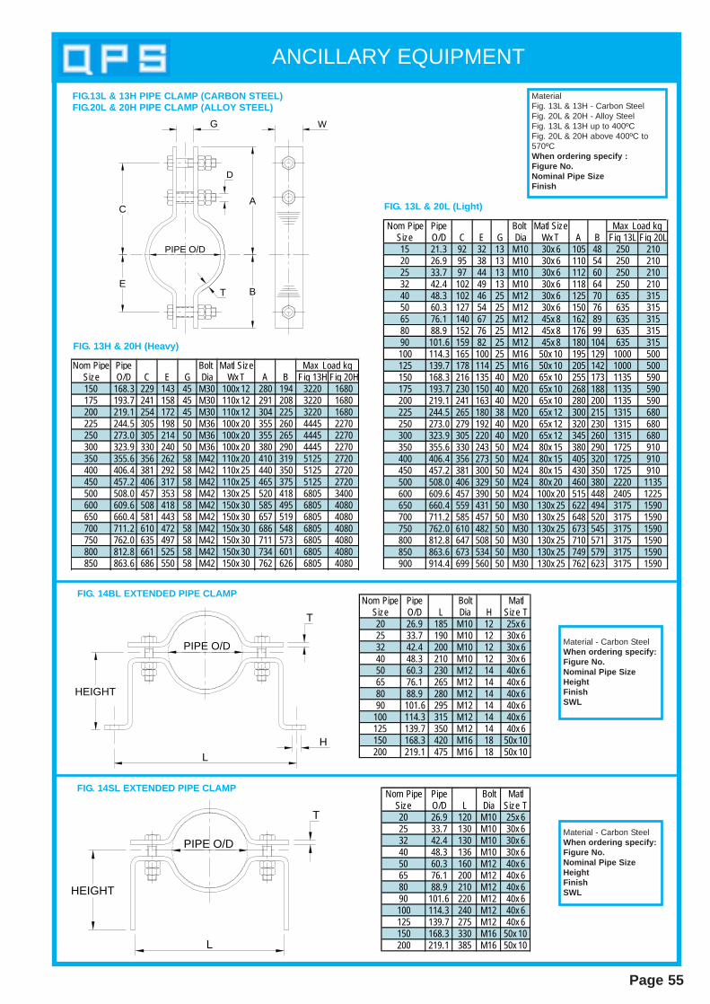
ANCILLARY EQUIPMENT
Nom Pipe Pipe Bolt Matl SizeSize O/D C E G Dia Wx T A B Fig 13H Fig 20H150 168.3 229 143 45 M30 100x 12 280 194 3220 1680175 193.7 241 158 45 M30 110x 12 291 208 3220 1680200 219.1 254 172 45 M30 110x 12 304 225 3220 1680225 244.5 305 198 50 M36 100x 20 355 260 4445 2270250 273.0 305 214 50 M36 100x 20 355 265 4445 2270300 323.9 330 240 50 M36 100x 20 380 290 4445 2270350 355.6 356 262 58 M42 110x 20 410 319 5125 2720400 406.4 381 292 58 M42 110x 25 440 350 5125 2720450 457.2 406 317 58 M42 110x 25 465 375 5125 2720500 508.0 457 353 58 M42 130x 25 520 418 6805 3400600 609.6 508 418 58 M42 150x 30 585 495 6805 4080650 660.4 581 443 58 M42 150x 30 657 519 6805 4080700 711.2 610 472 58 M42 150x 30 686 548 6805 4080750 762.0 635 497 58 M42 150x 30 711 573 6805 4080800 812.8 661 525 58 M42 150x 30 734 601 6805 4080850 863.6 686 550 58 M42 150x 30 762 626 6805 4080
Max Load kg
MaterialFig. 13L & 13H - Carbon SteelFig. 20L & 20H - Alloy SteelFig. 13L & 13H up to 400ºCFig. 20L & 20H above 400ºC to570ºCWhen ordering specify :Figure No.Nominal Pipe SizeFinish
PIPE O/D
L
T
HEIGHT
Material - Carbon SteelWhen ordering specify:Figure No.Nominal Pipe SizeHeightFinishSWL
Nom Pipe Pipe Bolt MatlSize O/D L Dia Size T20 26.9 120 M10 25x 625 33.7 130 M10 30x 632 42.4 130 M10 30x 640 48.3 136 M10 30x 650 60.3 160 M12 40x 665 76.1 200 M12 40x 680 88.9 210 M12 40x 690 101.6 220 M12 40x 6100 114.3 240 M12 40x 6125 139.7 275 M12 40x 6150 168.3 330 M16 50x 10200 219.1 385 M16 50x 10
FIG. 14SL EXTENDED PIPE CLAMP
Page 55
Nom Pipe Pipe Bolt Matl SizeSize O/D C E G Dia Wx T A B Fig 13L Fig 20L15 21.3 92 32 13 M10 30x 6 105 48 250 21020 26.9 95 38 13 M10 30x 6 110 54 250 21025 33.7 97 44 13 M10 30x 6 112 60 250 21032 42.4 102 49 13 M10 30x 6 118 64 250 21040 48.3 102 46 25 M12 30x 6 125 70 635 31550 60.3 127 54 25 M12 30x 6 150 76 635 31565 76.1 140 67 25 M12 45x 8 162 89 635 31580 88.9 152 76 25 M12 45x 8 176 99 635 31590 101.6 159 82 25 M12 45x 8 180 104 635 315100 114.3 165 100 25 M16 50x 10 195 129 1000 500125 139.7 178 114 25 M16 50x 10 205 142 1000 500150 168.3 216 135 40 M20 65x 10 255 173 1135 590175 193.7 230 150 40 M20 65x 10 268 188 1135 590200 219.1 241 163 40 M20 65x 10 280 200 1135 590225 244.5 265 180 38 M20 65x 12 300 215 1315 680250 273.0 279 192 40 M20 65x 12 320 230 1315 680300 323.9 305 220 40 M20 65x 12 345 260 1315 680350 355.6 330 243 50 M24 80x 15 380 290 1725 910400 406.4 356 273 50 M24 80x 15 405 320 1725 910450 457.2 381 300 50 M24 80x 15 430 350 1725 910500 508.0 406 329 50 M24 80x 20 460 380 2220 1135600 609.6 457 390 50 M24 100x 20 515 448 2405 1225650 660.4 559 431 50 M30 130x 25 622 494 3175 1590700 711.2 585 457 50 M30 130x 25 648 520 3175 1590750 762.0 610 482 50 M30 130x 25 673 545 3175 1590800 812.8 647 508 50 M30 130x 25 710 571 3175 1590850 863.6 673 534 50 M30 130x 25 749 579 3175 1590900 914.4 699 560 50 M30 130x 25 762 623 3175 1590
Max Load kg
FIG. 13L & 20L (Light)
FIG. 14BL EXTENDED PIPE CLAMP
Material - Carbon SteelWhen ordering specify:Figure No.Nominal Pipe SizeHeightFinishSWL
Nom Pipe Pipe Bolt MatlSize O/D L Dia H Size T20 26.9 185 M10 12 25x 625 33.7 190 M10 12 30x 632 42.4 200 M10 12 30x 640 48.3 210 M10 12 30x 650 60.3 230 M12 14 40x 665 76.1 265 M12 14 40x 680 88.9 280 M12 14 40x 690 101.6 295 M12 14 40x 6
100 114.3 315 M12 14 40x 6125 139.7 350 M12 14 40x 6150 168.3 420 M16 18 50x 10200 219.1 475 M16 18 50x 10
PIPE O/D
L
T
H
HEIGHT
PIPE O/D
E
C
T B
A
G
D
W
FIG. 13H & 20H (Heavy)
FIG.13L & 13H PIPE CLAMP (CARBON STEEL)FIG.20L & 20H PIPE CLAMP (ALLOY STEEL)
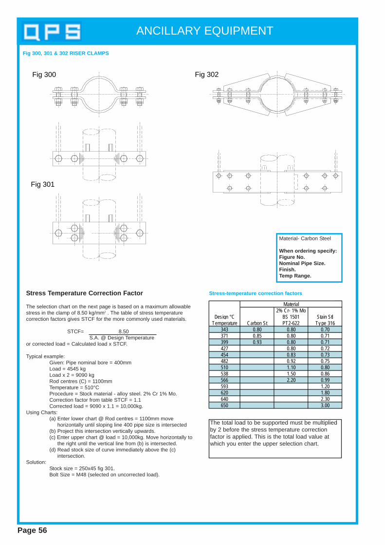
ANCILLARY EQUIPMENT
Page 56
Fig 300
Fig 301
Fig 302
Stress T emperature Correction Factor
The selection chart on the next page is based on a maximum allowablestress in the clamp of 8.50 kg/mm2 . The table of stress temperaturecorrection factors gives STCF for the more commonly used materials.
STCF= 8.50S.A. @ Design Temperature
or corrected load = Calculated load x STCF.
Typical example:Given: Pipe nominal bore = 400mmLoad = 4545 kgLoad x 2 = 9090 kgRod centres (C) = 1100mmTemperature = 510°CProcedure = Stock material - alloy steel. 2% Cr 1% Mo.Correction factor from table STCF = 1.1Corrected load = 9090 x 1.1 = 10,000kg.
Using Charts:(a) Enter lower chart @ Rod centres = 1100mm move
horizontally until sloping line 400 pipe size is intersected(b) Project this intersection vertically upwards.(c) Enter upper chart @ load = 10,000kg. Move horizontally to
the right until the vertical line from (b) is intersected.(d) Read stock size of curve immediately above the (c)
intersection.Solution:
Stock size = 250x45 fig 301.Bolt Size = M48 (selected on uncorrected load).
2% Cr- 1% MoDesign °C BS 1501 Stain Stl
Temperature Carbon St PT2-622 Ty pe 316343 0.80 0.80 0.70371 0.85 0.80 0.71399 0.93 0.80 0.71427 0.80 0.72454 0.83 0.73482 0.92 0.75510 1.10 0.80538 1.50 0.86566 2.20 0.99593 1.20620 1.80640 2.30650 3.00
Material
Fig 300, 301 & 302 RISER CLAMPS
Stress-temperature correction factors
Material- Carbon Steel
When ordering specify:Figure No.Nominal Pipe Size.Finish.Temp Range.
The total load to be supported must be multipliedby 2 before the stress temperature correctionfactor is applied. This is the total load value atwhich you enter the upper selection chart.

ANCILLARY EQUIPMENT
Page 57
Chart plot is for 8.5kg/mm2 allowablestress. Before entering chart multiply loadby stress temperature correction factor(see table). Read bolt diameter foruncorrected load.
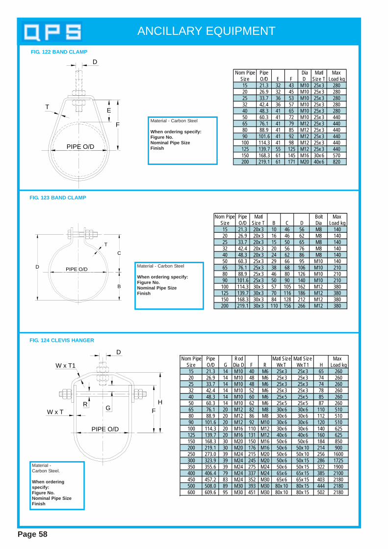
ANCILLARY EQUIPMENT
Page 58
Nom Pipe Pipe Dia Matl MaxSize O/D E F D Size T Load kg15 21.3 32 43 M10 25x 3 28020 26.9 32 45 M10 25x 3 28025 33.7 36 53 M10 25x 3 28032 42.4 36 57 M10 25x 3 28040 48.3 41 65 M10 25x 3 28050 60.3 41 72 M10 25x 3 44065 76.1 41 79 M12 25x 3 44080 88.9 41 85 M12 25x 3 44090 101.6 41 92 M12 25x 3 440100 114.3 41 98 M12 25x 3 440125 139.7 55 125 M12 25x 3 440150 168.3 61 145 M16 30x 6 570200 219.1 61 171 M20 40x 6 820
PIPE O/D
T E
F
D
Material - Carbon Steel
When ordering specify:Figure No.Nominal Pipe SizeFinish
FIG. 122 BAND CLAMP
PIPE O/D
C
B
D
T
Material - Carbon Steel
When ordering specify:Figure No.Nominal Pipe SizeFinish
FIG. 123 BAND CLAMP
Nom Pipe Pipe Rod Matl Size Matl Size Max Size O/D G Dia D F R Wx T Wx T1 H Load kg15 21.3 14 M10 40 M6 25x 3 25x 3 65 26020 26.9 14 M10 48 M6 25x 3 25x 3 74 26025 33.7 14 M10 48 M6 25x 3 25x 3 74 26032 42.4 14 M10 52 M6 25x 3 25x 3 78 26040 48.3 14 M10 60 M6 25x 5 25x 5 85 26050 60.3 14 M10 62 M6 25x 5 25x 5 87 26065 76.1 20 M12 82 M8 30x 6 30x 6 110 51080 88.9 20 M12 86 M8 30x 6 30x 6 112 51090 101.6 20 M12 92 M10 30x 6 30x 6 120 510100 114.3 20 M16 110 M12 30x 6 30x 6 140 625125 139.7 20 M16 131 M12 40x 6 40x 6 160 625150 168.3 30 M20 150 M16 50x 6 50x 6 184 850200 219.1 30 M20 176 M16 50x 6 50x 10 214 900250 273.0 39 M24 215 M20 50x 6 50x 10 256 1600300 323.9 39 M24 245 M20 50x 6 50x 15 286 1725350 355.6 39 M24 275 M24 50x 6 50x 15 322 1900400 406.4 79 M24 337 M24 65x 6 65x 15 385 2100450 457.2 83 M24 352 M30 65x 6 65x 15 403 2180500 508.0 89 M30 393 M30 80x 10 80x 15 444 2180600 609.6 95 M30 451 M30 80x 10 80x 15 502 2180
D
W x TR
G FH
W x T1
PIPE O/D
Material - Carbon Steel.
When orderingspecify:Figure No.Nominal Pipe SizeFinish
FIG. 124 CLEVIS HANGER
Nom Pipe Pipe Matl Bolt MaxSize O/D Size T B C D Dia Load kg15 21.3 20x 3 10 46 56 M8 14020 26.9 20x 3 16 46 62 M8 14025 33.7 20x 3 15 50 65 M8 14032 42.4 20x 3 20 56 76 M8 14040 48.3 20x 3 24 62 86 M8 14050 60.3 25x 3 29 66 95 M10 14065 76.1 25x 3 38 68 106 M10 21080 88.9 25x 3 46 80 126 M10 21090 101.6 25x 3 50 90 140 M10 210
100 114.3 30x 3 57 105 162 M12 380125 139.7 30x 3 70 116 186 M12 380150 168.3 30x 3 84 128 212 M12 380200 219.1 30x 3 110 156 266 M12 380
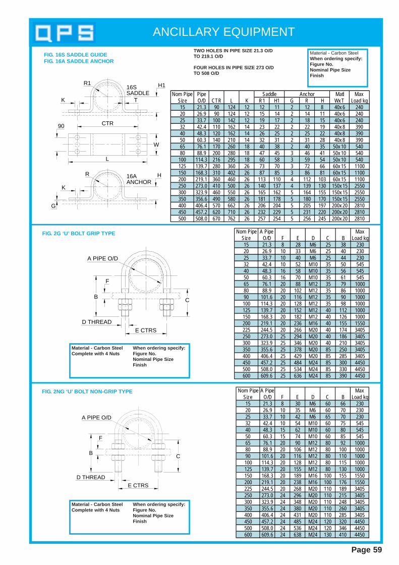
ANCILLARY EQUIPMENT
Page 59
Nom Pipe Pipe Matl MaxSize O/D CTR L K R1 H1 G R H Wx T Load kg15 21.3 90 124 12 12 11 2 12 8 40x 6 24020 26.9 90 124 12 15 14 2 14 11 40x 6 24025 33.7 100 142 12 19 17 2 18 15 40x 6 24032 42.4 110 162 14 23 22 2 22 19 40x 8 39040 48.3 120 162 14 26 25 2 25 22 40x 8 39050 60.3 140 210 14 32 31 2 31 28 40x 8 39065 76.1 170 260 18 40 38 2 40 35 50x 10 54080 88.9 200 280 18 47 45 3 46 41 50x 10 540
100 114.3 216 295 18 60 58 3 59 54 50x 10 540125 139.7 280 360 26 73 70 3 72 66 60x 15 1100150 168.3 310 402 26 87 85 3 86 81 60x 15 1100200 219.1 360 460 26 113 110 4 112 103 60x 15 1100250 273.0 410 500 26 140 137 4 139 130 150x 15 2550300 323.9 460 550 26 165 162 5 164 155 150x 15 2550350 356.6 490 580 26 181 178 5 180 170 150x 15 2550400 406.4 570 662 26 206 204 5 205 197 200x 20 2810450 457.2 620 710 26 232 229 5 231 220 200x 20 2810500 508.0 670 762 26 257 254 5 256 245 200x 20 2810
Saddle Anchor
CTR
L
W
K
H1
HR
R1
16AANCHOR
16SSADDLE
T
K
G
90
TWO HOLES IN PIPE SIZE 21.3 O/DTO 219.1 O/D
FOUR HOLES IN PIPE SIZE 273 O/DTO 508 O/D
Material - Carbon SteelWhen ordering specify:Figure No.Nominal Pipe SizeFinish
Nom Pipe A Pipe MaxSize O/D F E D C B Load kg15 21.3 8 28 M6 25 38 23020 26.9 10 33 M6 25 40 23025 33.7 10 40 M6 25 44 23032 42.4 10 52 M10 35 50 54540 48.3 16 58 M10 35 56 54550 60.3 16 70 M10 35 61 54565 76.1 20 88 M12 35 79 100080 88.9 20 102 M12 35 86 100090 101.6 20 116 M12 35 90 1000100 114.3 20 128 M12 35 98 1000125 139.7 20 152 M12 40 112 1000150 168.3 20 182 M12 40 126 1000200 219.1 20 236 M16 40 155 1550225 244.5 20 266 M20 40 174 3405250 273.0 25 294 M20 40 186 3405300 323.9 25 346 M20 40 210 3405350 355.6 25 378 M20 85 250 3405400 406.4 25 429 M20 85 285 3405450 457.2 25 484 M24 85 300 4450500 508.0 25 534 M24 85 330 4450600 609.6 25 636 M24 85 390 4450
E CTRSD THREAD
CB
A PIPE O/D
F
Material - Carbon S teel When ordering specify:Complete with 4 Nut s Figure No.
Nominal Pipe SizeFinish
FIG. 16S SADDLE GUIDEFIG. 16A SADDLE ANCHOR
FIG. 2G ‘U’ BOLT GRIP TYPE
Nom Pipe A Pipe MaxSize O/D F E D C B Load kg15 21.3 8 30 M6 60 66 23020 26.9 10 35 M6 60 70 23025 33.7 10 42 M6 65 70 23032 42.4 10 54 M10 60 75 54540 48.3 15 62 M10 60 80 54550 60.3 15 74 M10 60 85 54565 76.1 20 90 M12 80 92 100080 88.9 20 106 M12 80 100 100090 101.6 20 116 M12 80 110 1000100 114.3 20 128 M12 80 115 1000125 139.7 20 155 M12 80 130 1000150 168.3 20 189 M16 100 155 1550200 219.1 20 238 M16 100 176 1550225 244.5 20 268 M20 110 189 3405250 273.0 24 296 M20 110 215 3405300 323.9 24 348 M20 110 248 3405350 355.6 24 380 M20 110 260 3405400 406.4 24 431 M20 110 285 3405450 457.2 24 485 M24 120 320 4450500 508.0 24 536 M24 120 346 4450600 609.6 24 638 M24 130 410 4450
E CTRSD THREAD
CB
A PIPE O/D
F
FIG. 2NG ‘U’ BOLT NON-GRIP TYPE
Material - Carbon S teel When ordering specify:Complete with 4 Nut s Figure No.
Nominal Pipe SizeFinish
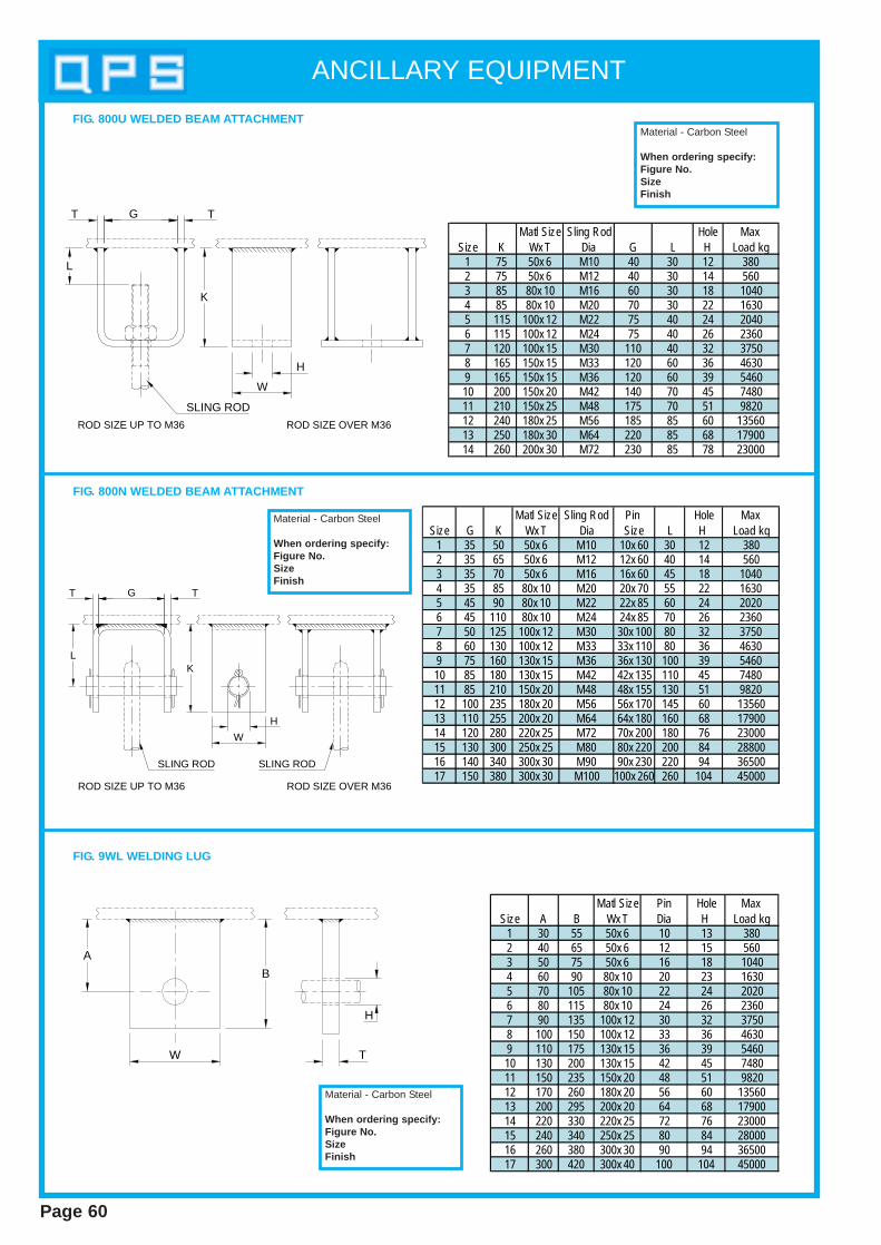
ANCILLARY EQUIPMENT
Page 60
FIG. 800U WELDED BEAM ATTACHMENT
Matl Size Sling Rod Hole MaxSize K Wx T Dia G L H Load kg
1 75 50x 6 M10 40 30 12 3802 75 50x 6 M12 40 30 14 5603 85 80x 10 M16 60 30 18 10404 85 80x 10 M20 70 30 22 16305 115 100x 12 M22 75 40 24 20406 115 100x 12 M24 75 40 26 23607 120 100x 15 M30 110 40 32 37508 165 150x 15 M33 120 60 36 46309 165 150x 15 M36 120 60 39 546010 200 150x 20 M42 140 70 45 748011 210 150x 25 M48 175 70 51 982012 240 180x 25 M56 185 85 60 1356013 250 180x 30 M64 220 85 68 1790014 260 200x 30 M72 230 85 78 23000
SLING ROD
L
T G T
K
W
H
Material - Carbon Steel
When ordering specify:Figure No.SizeFinish
Matl Size Sling Rod Pin Hole MaxSize G K Wx T Dia Size L H Load kg
1 35 50 50x 6 M10 10x 60 30 12 3802 35 65 50x 6 M12 12x 60 40 14 5603 35 70 50x 6 M16 16x 60 45 18 10404 35 85 80x 10 M20 20x 70 55 22 16305 45 90 80x 10 M22 22x 85 60 24 20206 45 110 80x 10 M24 24x 85 70 26 23607 50 125 100x 12 M30 30x 100 80 32 37508 60 130 100x 12 M33 33x 110 80 36 46309 75 160 130x 15 M36 36x 130 100 39 546010 85 180 130x 15 M42 42x 135 110 45 748011 85 210 150x 20 M48 48x 155 130 51 982012 100 235 180x 20 M56 56x 170 145 60 1356013 110 255 200x 20 M64 64x 180 160 68 1790014 120 280 220x 25 M72 70x 200 180 76 2300015 130 300 250x 25 M80 80x 220 200 84 2880016 140 340 300x 30 M90 90x 230 220 94 3650017 150 380 300x 30 M100 100x 260 260 104 45000
SLING ROD
L
T G T
K
W
H
ROD SIZE UP TO M36 ROD SIZE OVER M36
SLING ROD
ROD SIZE UP TO M36 ROD SIZE OVER M36
Material - Carbon Steel
When ordering specify:Figure No.SizeFinish
Matl Size Pin Hole MaxSize A B Wx T Dia H Load kg
1 30 55 50x 6 10 13 3802 40 65 50x 6 12 15 5603 50 75 50x 6 16 18 10404 60 90 80x 10 20 23 16305 70 105 80x 10 22 24 20206 80 115 80x 10 24 26 23607 90 135 100x 12 30 32 37508 100 150 100x 12 33 36 46309 110 175 130x 15 36 39 546010 130 200 130x 15 42 45 748011 150 235 150x 20 48 51 982012 170 260 180x 20 56 60 1356013 200 295 200x 20 64 68 1790014 220 330 220x 25 72 76 2300015 240 340 250x 25 80 84 2800016 260 380 300x 30 90 94 3650017 300 420 300x 40 100 104 45000
FIG. 800N WELDED BEAM ATTACHMENT
W T
B
A
H
FIG. 9WL WELDING LUG
Material - Carbon Steel
When ordering specify:Figure No.SizeFinish
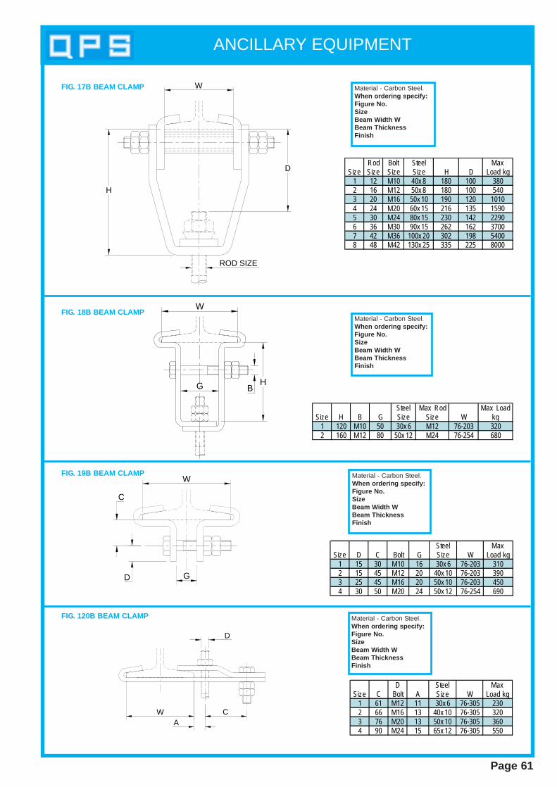
ANCILLARY EQUIPMENT
Page 61
W
H
D
ROD SIZE
Rod Bolt Steel MaxSize Size Size Size H D Load kg
1 12 M10 40x 8 180 100 3802 16 M12 50x 8 180 100 5403 20 M16 50x 10 190 120 10104 24 M20 60x 15 216 135 15905 30 M24 80x 15 230 142 22906 36 M30 90x 15 262 162 37007 42 M36 100x 20 302 198 54008 48 M42 130x 25 335 225 8000
Material - Carbon Steel.When ordering specify:Figure No.SizeBeam Width WBeam ThicknessFinish
FIG. 17B BEAM CLAMP
G
W
HB
Steel Max Rod Max LoadSize H B G Size Size W kg
1 120 M10 50 30x 6 M12 76-203 3202 160 M12 80 50x 12 M24 76-254 680
Material - Carbon Steel.When ordering specify:Figure No.SizeBeam Width WBeam ThicknessFinish
FIG. 18B BEAM CLAMP
W
D G
C
FIG. 19B BEAM CLAMP
Steel MaxSize D C Bolt G Size W Load kg
1 15 30 M10 16 30x 6 76-203 3102 15 45 M12 20 40x 10 76-203 3903 25 45 M16 20 50x 10 76-203 4504 30 50 M20 24 50x 12 76-254 690
Material - Carbon Steel.When ordering specify:Figure No.SizeBeam Width WBeam ThicknessFinish
WA
C
D
D Steel MaxSize C Bolt A Size W Load kg
1 61 M12 11 30x 6 76-305 2302 66 M16 13 40x 10 76-305 3203 76 M20 13 50x 10 76-305 3604 90 M24 15 65x 12 76-305 550
Material - Carbon Steel.When ordering specify:Figure No.SizeBeam Width WBeam ThicknessFinish
FIG. 120B BEAM CLAMP

ANCILLARY EQUIPMENT
Page 62
H
D
AB W
C
T
FIG. 121V BOLTED BEAM ATTACHMENT
Dia Hole Mat'l Max LoadSize C B D A H Wx T kg
1 75 153 M12 120 13 30x 10 5502 75 178 M16 135 15 40x 10 10203 90 200 M20 160 18 40x 12 16004 90 225 M24 175 23 50x 12 2250
Material - Carbon Steel.
When ordering specify:Figure No.SizeFinish
Size D M10 M12 M16 M20 M24 M30 M36 M42 M48 M56 M64 M72 M80 M90H 16 18 22 26 30 36 42 48 54 62 70 80 90 100
Max Load kg 360 530 1010 1580 2280 3650 5340 7400 10000 13600 17800 22300 28700 36250
H
300 STD
150
D
Material - Carbon Steel.
When ordering specify:Figure No.Size DLength if not st andardFinish
Size D M10 M12 M16 M20 M24 M30 M36 M42 M48 M56 M64 M72 M80H 25 30 30 40 50 75 75 100 70 80 80 100 110
Max Load Kg 380 560 1040 1630 2360 3750 5460 7480 9820 13560 17900 22300 28700
H
L
150D
FIG. 4B
Figure 4B will be tack weldedto figure 3R.Material - Carbon Steel
When ordering specify:Figure No.Size DLength LFinishThread: S tandard R/HL/H supplied on request
FIG. 3FR FORGED EYE RODTo BS3974 Pt. 1. Fig. 3
FIG. 3BR COMPOSITE EYE ROD
Size D M8 M10 M12 M16 M20 M24H 12 20 22 28 32 38
Max Load kg Unw elded 68 100 195 320 475 875Max Load kg Welded 215 370 555 1025 1605 2344
H
L
150D
Material - Carbon Steel.
When ordering specify:Figure No.Size DLength LFinishThread: S tandard R/HL/H Supplied on Request
FIG. 3ER EYE ROD (Unwelded)FIG. 3ERW EYE ROD (Welded)

ANCILLARY EQUIPMENT
Page 63
Size D M8 M10 M12 M16 M20 M24H 12 20 22 28 32 38
Max Load kg Unw elded 68 100 195 320 475 875Max Load kg Welded 215 370 555 1025 1605 2344
H
L
D
H
Material - Carbon SteelWhen ordering specify:Figure No.Size DLength LFinish
FIG. 3DE DOUBLE EYE ROD (Unwelded)FIG. 3DEW DOUBLE EYE ROD (Welded)
Size D M8 M10 M12 M16 M20 M24H 12 20 22 28 32 38
Max Load kg Unw elded 68 100 195 320 475 875Max Load kg Welded 215 370 555 1025 1605 2344
Material - Carbon SteelWhen ordering specify:Figure No.Size DLength L, M & NFinishThread: Standard R/HL/H supplied on request
150H
M N
D
L
150
FIG. 3LE LINKED EYE ROD (Unwelded)FIG. 3LEW LINKED EYE ROD (Welded)
Size D M10 M12 M16 M20 M24Max Load kg 110 210 330 465 860
Material - Carbon SteelWhen ordering specify:Figure No.Size DLength LFinishThread: Standard R/HL/H supplied on request
L
150RAD 0.6 x D D
FIG. 3J J BOLT
D Dia M8 M10 M12 M16 M20 M24 M30 M36M/Sqx A 22x 30 22x 30 22x 35 30x 40 30x 50 40x 60 50x 80 55x 90
B 17 20 23 30 36 41 53 60H Dia 9 13 15 18 23 27 33 38
C 9 11 13 18 20 24 30 36Max Load (kg) 215 375 540 1035 1610 2350 3678 5205
Material - Carbon SteelWhen ordering specify:Figure No.Size DLength LFinishThread: Standard R/HL/H supplied on request
L
150D
M
BA
CH DIA
FIG. 3CR COMPOSITE EYE ROD

Size D M10 M12 M16 M20 M24 M30 M36 M42 M48 M56 M64 M72 M80 M90Max Load (kg) 385 565 1050 1635 2370 3755 5475 7495 9840 13625 18010 22805 28700 36250
FIG. 3R TIE ROD Material - Carbon SteelWhen ordering specify:Figure No.Size DLength LFinishThread: S tandard R/HL/H supplied on request
Size D M6 M8 M10 M12 M16 M20 M24 M30 M36 M42 M48 M56 M64 M72 M80 M90Max Load (kg) 130 235 385 565 1050 1635 2370 3755 5475 7495 9840 13625 18010 22805 28700 36250
D
L
Material - Carbon SteelWhen ordering specify:Figure No.Size DLength LFinishThread: S tandard R/HL/H supplied on request
FIG. 3AR ALL THREAD ROD
Max LoadSize W B kgM10 32 184 370M12 35 200 550M16 40 205 1045M20 50 218 1610M24 63 218 2350M30 85 224 3650M36 85 230 5360M42 90 236 7445M48 90 244 9795M56 120 252 13490M64 120 270 17900M72 150 300 22740M80 172 392 28125
150 STD
W
B
RIGHT HAND THREADLEFT HAND THREAD
Material - Forged SteelBS970 Pt 1 Gr080 A27When ordering specify:Figure No.SizeFinish
FIG. 4T FORGED TURNBUCKLE
B
T
DE
AC
Material - Forged SteelBS970 Pt 1 Gr080 A27Sizes M48 upward, typechange.When ordering specify:Figure No.Size TFinishThread: S tandard R/H
Size D Max LoadT A B C Dia E kg
M8 6 25 64 32 16 240M10 7 25 64 32 16 380M12 9 30 73 38 18 560M16 12 30 73 38 18 1040M20 14 40 102 45 25 1630M24 17 50 124 50 28 2360M30 21 75 146 70 38 3750M36 26 75 146 70 38 5460M42 30 100 180 80 45 7480M48 31 70 240 100 75 9820M56 36 80 270 100 80 13560M64 42 100 330 130 80 17900M72 47 100 330 130 80 22740M80 49 101 360 130 89 28125
FIG. 4B WELDLESS BOWNUT(To BS3974 Part 1)
A D
Size D M10 M12 M16 M20 M24 M30 M36 M42 M48 M56 M64 M72 M80A 45 45 55 55 70 75 110 120 130 150 175 200 230
Max Load kg 385 565 1050 1635 2370 3755 5475 7495 9840 13625 18010 22805 28700
Material - Carbon Steel.Tapped RH Thread.When ordering specify:Figure No.Size DFinishThread: S tandard R/H
FIG. 4RC ROD COUPLING
150D150
L
ANCILLARY EQUIPMENT
Page 64

S
V
L
W
C
T
D
Size D S V L C T W Max Load kg1 M10 35 20 85 37 12 42 3602 M12 35 25 85 37 12 42 5253 M16 40 30 85 37 12 46 10154 M20 40 35 85 37 12 46 15955 M24 70 40 85 40 14 62 23106 M30 70 50 85 40 14 62 37157 M36 80 55 100 46 14 74 52158 M42 85 60 100 51 14 80 74009 M48 90 70 120 63 20 100 9605
10 M56 110 80 140 65 22 104 1299011 M64 120 90 160 75 22 108 1750512 M72 140 100 180 80 25 168 2280513 M80 160 120 200 90 25 168 28700
Material - Carbon Steel.When ordering specify:Figure No.SizeFinish
FIG. 4SC CLEVIS
Nom Pipe Pipe MaxSize O/D A C D H L Load kg25 33.7 20 27 15 11 27 14032 42.4 21 32 15 11 38 14040 48.3 22 35 16 11 40 14050 60.3 24 41 16 11 44 14065 76.1 29 49 21 14 60 27280 88.9 35 57 24 14 95 270
100 114.3 35 71 24 14 95 315125 139.7 49 87 31 21 146 315150 168.3 49 103 31 21 146 455200 219.1 69 130 38 24 228 590250 273.0 85 159 44 27 280 770300 323.9 100 189 50 27 332 1040350 355.6 120 213 66 27 361 1395400 406.4 130 240 67 27 414 1395450 457.2 138 267 70 27 463 1900500 508.0 152 295 76 33 514 2050600 609.6 183 365 92 33 618 2700750 762.0 219 443 100 50 770 3200900 914.4 251 521 110 66 914 4900
cTOOF PIPE
C
H
L
A
D
FIG. 500 CAST PIPE ROLLER
Material - Cast Iron.
When ordering specify:Figure No.Nominal Pipe SizeFinish
Nom Pipe Pipe Rod MaxSize O/D A C B H L Dia Load kg50 60.3 45 46 32 14 67 M12 18065 76.1 45 52 32 14 67 M12 18080 88.9 45 62 32 14 67 M12 18090 101.6 45 68 32 14 67 M12 180100 114.3 54 71 38 14 93 M12 435125 139.7 54 87 38 14 93 M12 435150 168.3 54 102 38 14 93 M12 435175 193.7 54 117 38 14 93 M12 435200 219.1 90 133 52 22 153 M20 1000250 273.0 90 162 52 22 153 M20 1000300 323.9 98 190 58 26 205 M24 1370350 355.6 98 206 58 26 205 M24 1370400 406.4 115 235 80 32 232 M30 2230450 457.2 115 263 80 32 232 M30 2230500 508.0 115 292 80 32 232 M30 2230600 609.6 115 350 80 38 255 M36 2790650 660.4 136 380 104 44 320 M42 3500700 711.2 136 406 104 44 320 M42 3500750 762.0 136 438 104 44 320 M42 3500800 812.8 159 460 112 50 379 M48 5300900 914.4 159 514 112 50 379 M48 5300
1050 1066.8 159 590 112 50 379 M48 53001200 1219.2 159 667 112 50 379 M48 5300
Material - Cast Iron.
When ordering specify:Figure No.Nominal Pipe SizeFinish
C
OF PIPETO
L
c
A B
H
FIG. 501 CAST PIPE ROLLER (Heavy Duty)
ANCILLARY EQUIPMENT
Page 65

ANCILLARY EQUIPMENT
Page 66
Nom Pipe Pipe Dia Max Size O/D C L D H Load kg50 60.3 41 116 M10 97 25065 76.1 49 125 M12 120 29080 88.9 57 150 M12 120 320
100 114.3 71 182 M12 120 340125 139.7 87 216 M16 120 340150 168.3 103 255 M16 120 480200 219.1 130 306 M20 140 580250 273.0 159 356 M24 140 770300 323.9 189 408 M36 155 1060350 355.6 213 435 M36 185 1380400 406.4 240 490 M36 208 1790450 457.2 267 555 M36 230 1880500 508.0 295 635 M36 260 1965600 609.6 365 735 M36 360 2750
Material - Cast Iron.
When ordering specify:Figure No.Nominal Pipe SizeFinish
L
C
H
D
CENTRE LINE OF PIPE
FIG. 510 ROLLER SUPPORT
Nom Pipe Pipe MaxSize Size O/D A W L CTR T H Load kg
1 50 60.3 75 130 215 160 8 45 1802 65 76.1 75 130 215 160 8 45 1803 80 88.9 75 130 215 160 8 45 1804 90 101.6 75 130 215 160 8 45 1805 100 114.3 105 130 260 200 8 55 4356 125 139.7 105 130 260 200 8 55 4357 150 168.3 105 130 260 200 8 55 4358 200 219.1 160 140 255 100 10 90 10009 250 273.0 160 140 255 100 10 90 1000
10 300 323.9 210 200 270 145 10 113 137011 350 355.6 210 200 270 145 10 113 137012 400 406.4 242 200 270 170 12 133 223013 450 457.2 242 200 310 170 12 133 223014 500 508.0 242 200 310 170 12 133 223015 600 609.6 264 250 330 190 12 133 279016 650 660.4 329 300 510 250 15 143 350017 700 711.2 329 300 510 250 15 143 350018 750 762.0 329 300 510 250 15 143 3500
Material - Carbon Steeland Cast Iron Roller Fig. 501
When ordering specify:Figure No.Nominal Pipe SizeFinish
CTR
AL
26 DIA
T
H
W
FIG. 520 ROLLER CHAIR
Nom Pipe Pipe MaxNo. Size O/D A W L D B T Load kg1 50 60.3 157 150 215 M16 100 12 1802 65 76.1 157 150 215 M16 100 12 1803 80 88.9 157 150 215 M16 100 12 1804 90 101.6 157 150 215 M16 100 12 1805 100 114.3 205 150 260 M16 100 12 4356 125 139.7 205 150 260 M16 100 12 4357 150 168.5 205 150 260 M16 100 12 4358 200 219.1 135 150 255 M20 114 15 10009 250 273.0 135 150 255 M20 114 15 1000
10 300 323.9 205 200 270 M20 145 20 137011 350 355.6 205 200 270 M24 145 20 137012 400 406.4 248 200 310 M24 150 25 223013 450 457.2 248 200 310 M24 150 25 223014 500 508.0 248 200 310 M24 150 25 223015 600 609.6 254 250 330 M30 178 25 279016 650 660.4 432 300 510 M30 230 25 350017 700 711.2 432 300 510 M30 230 25 350018 750 762.0 432 300 510 M30 230 25 3500
AL W
26 DIA
B
D
T
Material - Carbon Steel and Cast IronRollerFig. 501
When ordering specify:Figure No.Nominal Pipe SizeFinish
FIG. 530 ADJUSTABLE ROLLER CHAIR
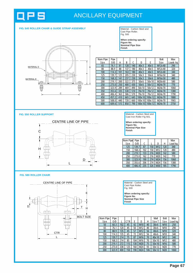
ANCILLARY EQUIPMENT
Page 67
Nom Pipe Pipe Bolt MaxSize O/D A B C D E Size Loads kg65 76.1 81 128 140 40x 3 40x 5 M12x 40 29080 88.9 88 137 180 40x 3 40x 5 M12x 40 320100 114.3 101 163 180 40x 3 40x 5 M12x 40 340125 139.7 125 205 230 50x 3 50x 6 M16x 50 340150 168.3 141 237 230 50x 3 50x 6 M16x 50 480200 219.1 200 322 375 50x 6 50x 10 M20x 60 580250 273.0 250 400 430 50x 6 50x 12 M24x 70 770300 323.9 289 469 490 50x 10 50x 12 M24x 70 1060350 355.6 335 530 510 70x 10 70x 12 M24x 70 1380400 406.4 363 586 570 70x 10 70x 12 M24x 70 1790450 457.2 410 665 645 100x 10 100x 12 M24x 70 1880500 508.0 440 720 660 100x 10 100x 12 M24x 70 1965600 609.6 515 850 790 100x 10 100x 12 M24x 70 2750
FIG. 540 ROLLER CHAIR & GUIDE STRAP ASSEMBLY
FIG. 580 ROLLER CHAIR
L
D
E
HT
BOLT SIZE
CTR
CENTRE LINE OF PIPE
Nom Pipe Pipe Matl Bolt MaxSize O/D L CTR E D H Size T Size Load kg50 60.3 102 45 42 M10 40 30x 6 M10 25065 76.1 120 45 50 M12 40 30x 6 M10 29080 88.9 135 45 57 M12 56 40x 6 M10 320
100 114.3 135 65 72 M12 56 40x 6 M10 340125 139.7 214 75 87 M16 70 40x 10 M12 340150 168.3 214 85 104 M16 70 50x 10 M12 480200 219.1 272 115 130 M20 75 50x 10 M16 580250 273.0 338 125 160 M24 93 50x 12 M20 770300 323.9 400 150 190 M24 106 50x 12 M20 1060
Material - Carbon Steel andCast Pipe Roller.Fig. 500
When ordering specify:Figure No.Nominal Pipe SizeFinish
Nom Pipe Pipe Max Size O/D C L D H Load kg125 139.7 87 150 M12 120 340150 168.3 102 150 M12 120 480200 219.1 133 216 M20 142 580250 273.0 162 216 M20 142 770300 323.9 190 274 M24 156 1060350 355.6 206 274 M24 156 1380400 406.4 235 326 M30 185 1790
FIG. 550 ROLLER SUPPORT
D
CENTRE LINE OF PIPE
L
C
H
Material - Carbon Steel andCast Iron Roller Fig 501.
When ordering specify:Figure No.Nominal Pipe SizeFinish
Material - Carbon Steel andCast Pipe Roller.Fig. 500
When ordering specify:Figure No.Nominal Pipe SizeFinish
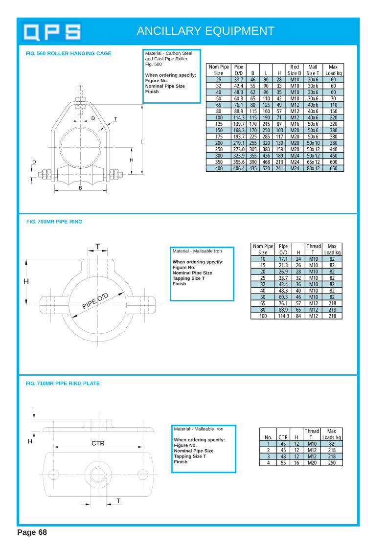
ANCILLARY EQUIPMENT
Page 68
Nom Pipe Pipe Rod Matl MaxSize O/D B L H Size D Size T Load kg25 33.7 46 90 28 M10 30x 6 6032 42.4 55 90 33 M10 30x 6 6040 48.3 62 96 35 M10 30x 6 6050 60.3 65 110 42 M10 30x 6 7065 76.1 80 125 49 M12 40x 6 11080 88.9 115 160 57 M12 40x 6 150100 114.3 115 190 71 M12 40x 6 220125 139.7 170 215 87 M16 50x 6 320150 168.3 170 250 103 M20 50x 6 380175 193.7 225 285 117 M20 50x 6 380200 219.1 255 320 130 M20 50x 10 380250 273.0 305 380 159 M20 50x 12 440300 323.9 355 436 189 M24 50x 12 460350 355.6 390 468 213 M24 65x 12 600400 406.4 435 520 241 M24 80x 12 650
B
H
L
D
D
T
FIG. 560 ROLLER HANGING CAGE Material - Carbon Steeland Cast Pipe RollerFig. 500
When ordering specify:Figure No.Nominal Pipe SizeFinish
Nom Pipe Pipe Thread MaxSize O/D H T Load kg10 17.1 24 M10 8215 21.3 26 M10 8220 26.9 28 M10 8225 33.7 32 M10 8232 42.4 36 M10 8240 48.3 40 M10 8250 60.3 46 M10 8265 76.1 57 M12 21880 88.9 65 M12 218100 114.3 84 M12 218
H
TMaterial - Malleable Iron
When ordering specify:Figure No.Nominal Pipe SizeTapping Size TFinish
Thread MaxNo. CTR H T Loads kg1 45 12 M10 822 45 12 M12 2183 48 12 M12 2184 55 16 M20 250
Material - Malleable Iron
When ordering specify:Figure No.Nominal Pipe SizeTapping Size TFinish
H CTR
T
FIG. 700MR PIPE RING
FIG. 710MR PIPE RING PLATE
PIPE O/D
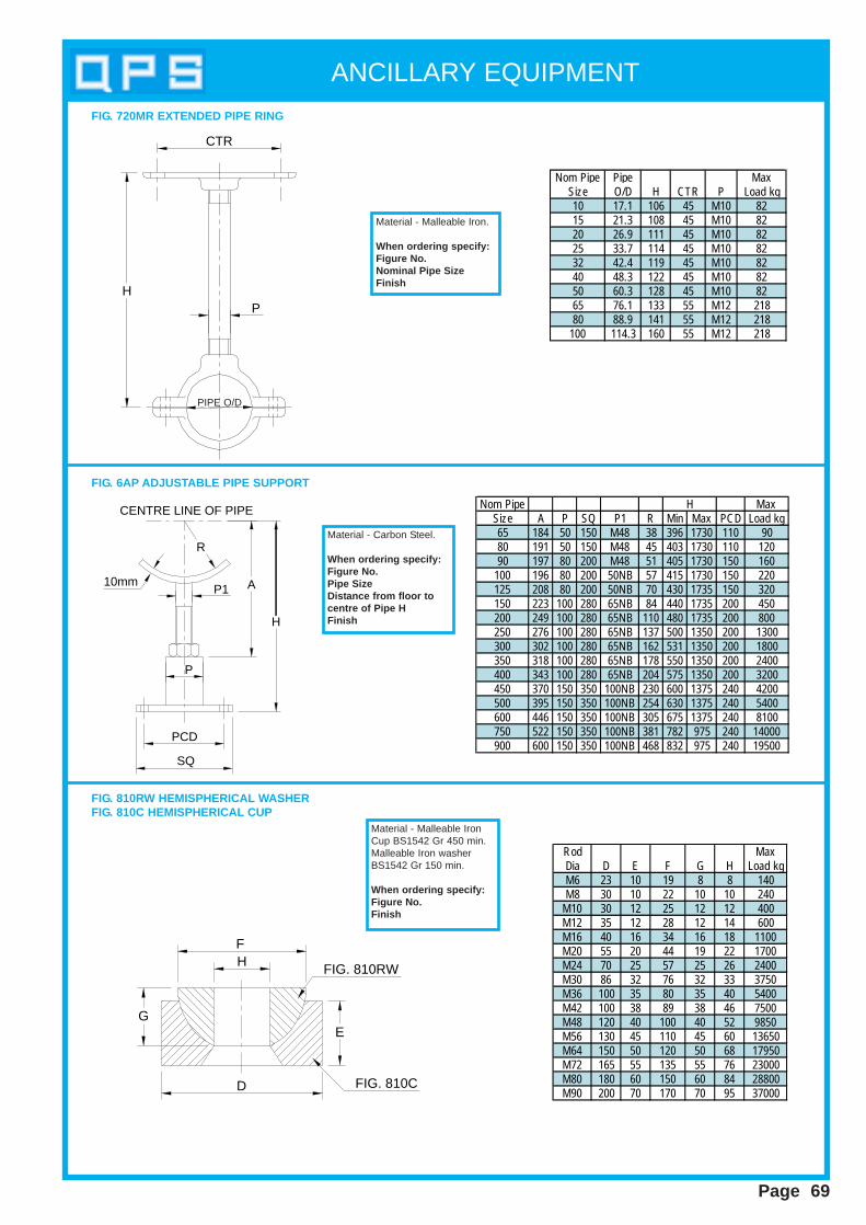
Page 69
ANCILLARY EQUIPMENT
Nom Pipe Pipe MaxSize O/D H CTR P Load kg10 17.1 106 45 M10 8215 21.3 108 45 M10 8220 26.9 111 45 M10 8225 33.7 114 45 M10 8232 42.4 119 45 M10 8240 48.3 122 45 M10 8250 60.3 128 45 M10 8265 76.1 133 55 M12 21880 88.9 141 55 M12 218
100 114.3 160 55 M12 218
CTR
PH
Material - Malleable Iron.
When ordering specify:Figure No.Nominal Pipe SizeFinish
FIG. 720MR EXTENDED PIPE RING
Nom Pipe MaxSize A P SQ P1 R Min Max PCD Load kg65 184 50 150 M48 38 396 1730 110 9080 191 50 150 M48 45 403 1730 110 12090 197 80 200 M48 51 405 1730 150 160
100 196 80 200 50NB 57 415 1730 150 220125 208 80 200 50NB 70 430 1735 150 320150 223 100 280 65NB 84 440 1735 200 450200 249 100 280 65NB 110 480 1735 200 800250 276 100 280 65NB 137 500 1350 200 1300300 302 100 280 65NB 162 531 1350 200 1800350 318 100 280 65NB 178 550 1350 200 2400400 343 100 280 65NB 204 575 1350 200 3200450 370 150 350 100NB 230 600 1375 240 4200500 395 150 350 100NB 254 630 1375 240 5400600 446 150 350 100NB 305 675 1375 240 8100750 522 150 350 100NB 381 782 975 240 14000900 600 150 350 100NB 468 832 975 240 19500
H
Material - Carbon Steel.
When ordering specify:Figure No.Pipe SizeDistance from floor tocentre of Pipe HFinish
FIG. 6AP ADJUSTABLE PIPE SUPPORT
H
P1
SQ
P
10mm
CENTRE LINE OF PIPE
R
A
PCD
Rod MaxDia D E F G H Load kgM6 23 10 19 8 8 140M8 30 10 22 10 10 240
M10 30 12 25 12 12 400M12 35 12 28 12 14 600M16 40 16 34 16 18 1100M20 55 20 44 19 22 1700M24 70 25 57 25 26 2400M30 86 32 76 32 33 3750M36 100 35 80 35 40 5400M42 100 38 89 38 46 7500M48 120 40 100 40 52 9850M56 130 45 110 45 60 13650M64 150 50 120 50 68 17950M72 165 55 135 55 76 23000M80 180 60 150 60 84 28800M90 200 70 170 70 95 37000
HF
GE
D
FIG. 810RW
FIG. 810C
FIG. 810RW HEMISPHERICAL WASHERFIG. 810C HEMISPHERICAL CUP
Material - Malleable IronCup BS1542 Gr 450 min.Malleable Iron washerBS1542 Gr 150 min.
When ordering specify:Figure No.Finish
PIPE O/D
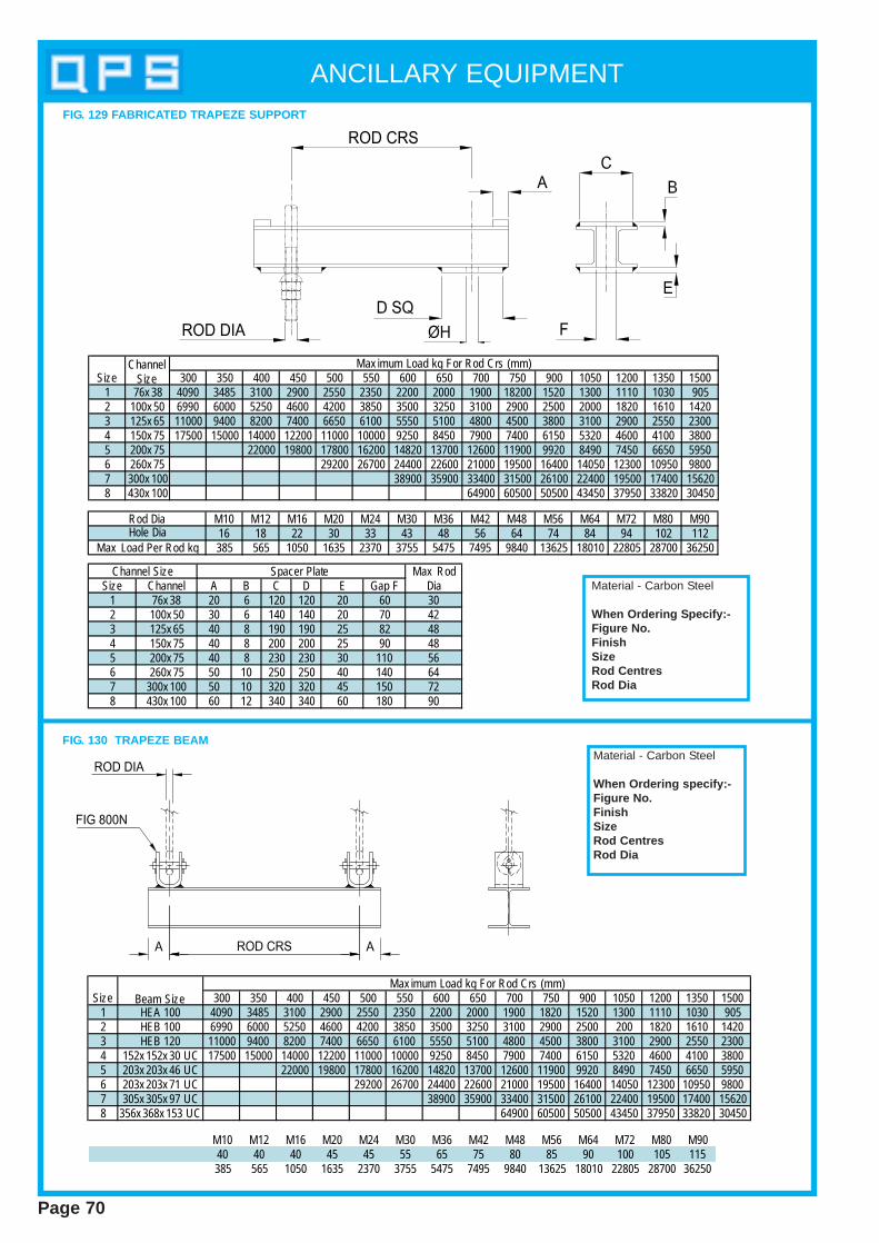
Page 70
ANCILLARY EQUIPMENT
Size Beam Size 300 350 400 450 500 550 600 650 700 750 900 1050 1200 1350 15001 HEA 100 4090 3485 3100 2900 2550 2350 2200 2000 1900 1820 1520 1300 1110 1030 9052 HEB 100 6990 6000 5250 4600 4200 3850 3500 3250 3100 2900 2500 200 1820 1610 14203 HEB 120 11000 9400 8200 7400 6650 6100 5550 5100 4800 4500 3800 3100 2900 2550 23004 152x 152x 30 UC 17500 15000 14000 12200 11000 10000 9250 8450 7900 7400 6150 5320 4600 4100 38005 203x 203x 46 UC 22000 19800 17800 16200 14820 13700 12600 11900 9920 8490 7450 6650 59506 203x 203x 71 UC 29200 26700 24400 22600 21000 19500 16400 14050 12300 10950 98007 305x 305x 97 UC 38900 35900 33400 31500 26100 22400 19500 17400 156208 356x 368x 153 UC 64900 60500 50500 43450 37950 33820 30450
Max imum Load kg For Rod Crs (mm)
M10 M12 M16 M20 M24 M30 M36 M42 M48 M56 M64 M72 M80 M9040 40 40 45 45 55 65 75 80 85 90 100 105 115385 565 1050 1635 2370 3755 5475 7495 9840 13625 18010 22805 28700 36250
FIG. 130 TRAPEZE BEAMMaterial - Carbon Steel
When Ordering specify:-Figure No.Finish SizeRod CentresRod Dia
Channel Size Size 300 350 400 450 500 550 600 650 700 750 900 1050 1200 1350 1500
1 76x 38 4090 3485 3100 2900 2550 2350 2200 2000 1900 18200 1520 1300 1110 1030 9052 100x 50 6990 6000 5250 4600 4200 3850 3500 3250 3100 2900 2500 2000 1820 1610 14203 125x 65 11000 9400 8200 7400 6650 6100 5550 5100 4800 4500 3800 3100 2900 2550 23004 150x 75 17500 15000 14000 12200 11000 10000 9250 8450 7900 7400 6150 5320 4600 4100 38005 200x 75 22000 19800 17800 16200 14820 13700 12600 11900 9920 8490 7450 6650 59506 260x 75 29200 26700 24400 22600 21000 19500 16400 14050 12300 10950 98007 300x 100 38900 35900 33400 31500 26100 22400 19500 17400 156208 430x 100 64900 60500 50500 43450 37950 33820 30450
Max imum Load kg For Rod Crs (mm)
Max RodSize Channel A B C D E Gap F Dia
1 76x 38 20 6 120 120 20 60 302 100x 50 30 6 140 140 20 70 423 125x 65 40 8 190 190 25 82 484 150x 75 40 8 200 200 25 90 485 200x 75 40 8 230 230 30 110 566 260x 75 50 10 250 250 40 140 647 300x 100 50 10 320 320 45 150 728 430x 100 60 12 340 340 60 180 90
Channel Size Spacer Plate
M10 M12 M16 M20 M24 M30 M36 M42 M48 M56 M64 M72 M80 M9016 18 22 30 33 43 48 56 64 74 84 94 102 112385 565 1050 1635 2370 3755 5475 7495 9840 13625 18010 22805 28700 36250Max Load Per Rod kg
Hole DiaRod Dia
Material - Carbon Steel
When Ordering S pecify:-Figure No.FinishSizeRod CentresRod Dia
FIG. 129 FABRICATED TRAPEZE SUPPORT
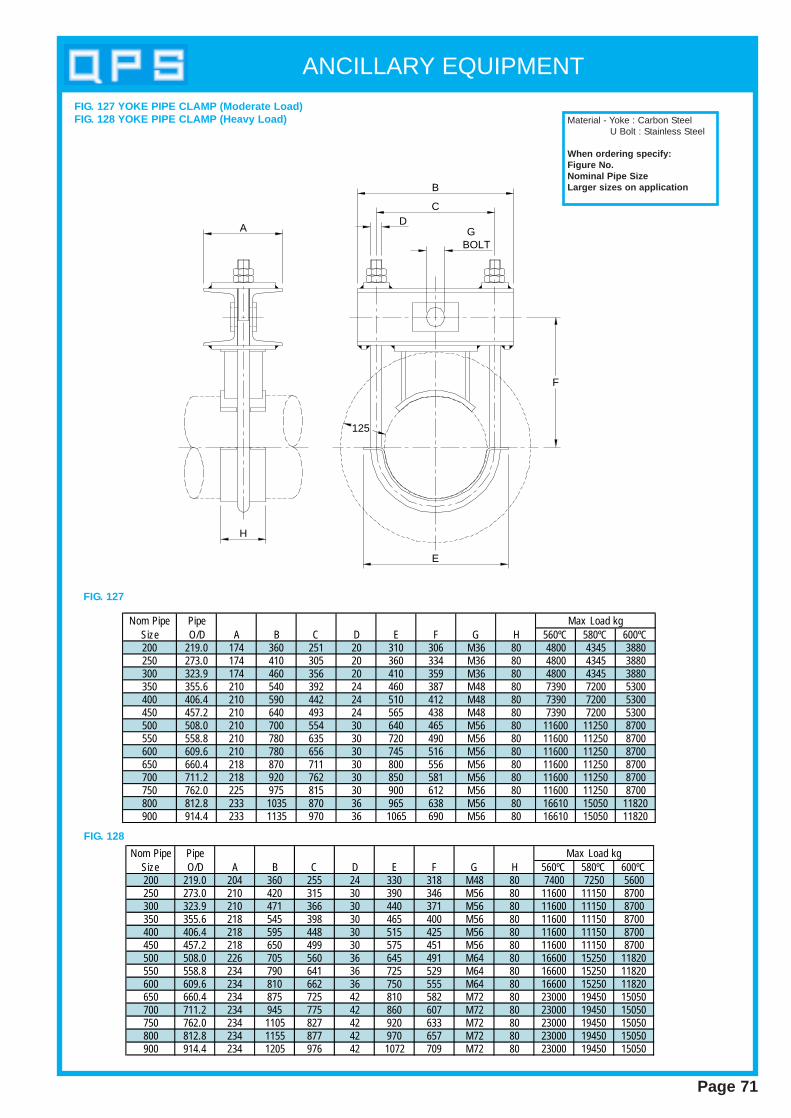
Page 71
ANCILLARY EQUIPMENT
A
B
CD
G BOLT
F
H
E
125
FIG. 127 YOKE PIPE CLAMP (Moderate Load)FIG. 128 YOKE PIPE CLAMP (Heavy Load)
FIG. 127
FIG. 128
Material - Yoke : Carbon SteelU Bolt : Stainless Steel
When ordering specify:Figure No.Nominal Pipe SizeLarger sizes on application
Nom Pipe Pipe Max Load kgSize O/D A B C D E F G H 560ºC 580ºC 600ºC200 219.0 174 360 251 20 310 306 M36 80 4800 4345 3880250 273.0 174 410 305 20 360 334 M36 80 4800 4345 3880300 323.9 174 460 356 20 410 359 M36 80 4800 4345 3880350 355.6 210 540 392 24 460 387 M48 80 7390 7200 5300400 406.4 210 590 442 24 510 412 M48 80 7390 7200 5300450 457.2 210 640 493 24 565 438 M48 80 7390 7200 5300500 508.0 210 700 554 30 640 465 M56 80 11600 11250 8700550 558.8 210 780 635 30 720 490 M56 80 11600 11250 8700600 609.6 210 780 656 30 745 516 M56 80 11600 11250 8700650 660.4 218 870 711 30 800 556 M56 80 11600 11250 8700700 711.2 218 920 762 30 850 581 M56 80 11600 11250 8700750 762.0 225 975 815 30 900 612 M56 80 11600 11250 8700800 812.8 233 1035 870 36 965 638 M56 80 16610 15050 11820900 914.4 233 1135 970 36 1065 690 M56 80 16610 15050 11820
Nom Pipe Pipe Max Load kgSize O/D A B C D E F G H 560ºC 580ºC 600ºC200 219.0 204 360 255 24 330 318 M48 80 7400 7250 5600250 273.0 210 420 315 30 390 346 M56 80 11600 11150 8700300 323.9 210 471 366 30 440 371 M56 80 11600 11150 8700350 355.6 218 545 398 30 465 400 M56 80 11600 11150 8700400 406.4 218 595 448 30 515 425 M56 80 11600 11150 8700450 457.2 218 650 499 30 575 451 M56 80 11600 11150 8700500 508.0 226 705 560 36 645 491 M64 80 16600 15250 11820550 558.8 234 790 641 36 725 529 M64 80 16600 15250 11820600 609.6 234 810 662 36 750 555 M64 80 16600 15250 11820650 660.4 234 875 725 42 810 582 M72 80 23000 19450 15050700 711.2 234 945 775 42 860 607 M72 80 23000 19450 15050750 762.0 234 1105 827 42 920 633 M72 80 23000 19450 15050800 812.8 234 1155 877 42 970 657 M72 80 23000 19450 15050900 914.4 234 1205 976 42 1072 709 M72 80 23000 19450 15050

Page 72
ANCILLARY EQUIPMENT
A
T
B
EC
Material - Carbon Steel
When ordering specify:Figure No.Beam Width BBeam Flange Thickness T
T
C B
A
E
Material - Carbon Steel
When ordering specify:Figure No.Beam Width BBeam Flange Thickness T
FIG. 126 ADJUSTABLE BEAM ATTACHMENT
FIG. 125 ADJUSTABLE BEAM ATTACHMENT
Max Loadkg
B + 150 * 140 M16 * 1045
E Max TA B C
E MaxB C Max T Load kg
M16 * 1045Min=B/2 + 120Max =1000
* 140
A
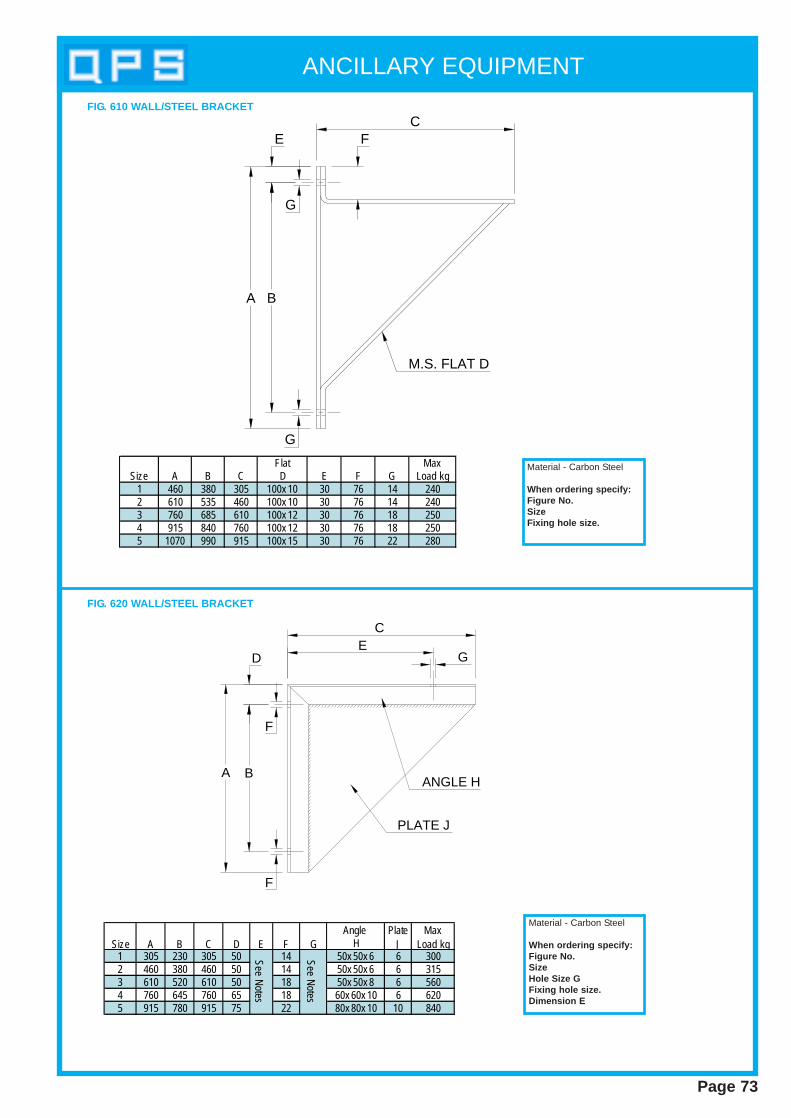
Page 73
ANCILLARY EQUIPMENT
G
E
BA
FC
G
M.S. FLAT D
Material - Carbon Steel
When ordering specify:Figure No.SizeFixing hole size.
FIG. 610 WALL/STEEL BRACKET
GE
C
D
F
F
BAANGLE H
PLATE J
Material - Carbon Steel
When ordering specify:Figure No.SizeHole Size GFixing hole size.Dimension E
FIG. 620 WALL/STEEL BRACKET
MaxSize A B C E F G Load kg
1 460 380 305 30 76 14 2402 610 535 460 30 76 14 2403 760 685 610 30 76 18 2504 915 840 760 30 76 18 2505 1070 990 915 30 76 22 280
Flat
100x 10100x 10100x 12
D
100x 12100x 15
Plate MaxSize A B C D E F G J Load kg
1 305 230 305 50 14 6 3002 460 380 460 50 14 6 3153 610 520 610 50 18 6 5604 760 645 760 65 18 6 6205 915 780 915 75 22 10 840
See Notes
See Notes
80x 80x 10
50x 50x 860x 60x 10
50x 50x 650x 50x 6
Angle H
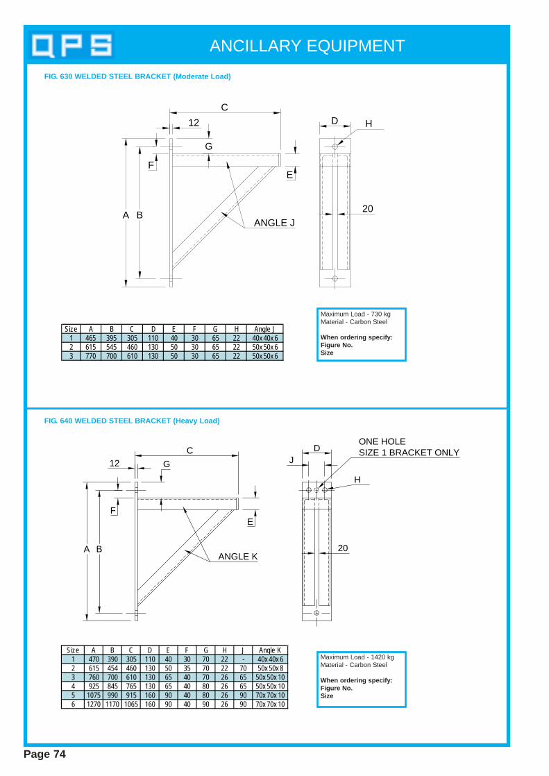
Page 74
ANCILLARY EQUIPMENT
FIG. 630 WELDED STEEL BRACKET (Moderate Load)
12
C
E
G
F
BA20
D H
ANGLE J
Size A B C D E F G H Angle J1 465 395 305 110 40 30 65 22 40x 40x 62 615 545 460 130 50 30 65 22 50x 50x 63 770 700 610 130 50 30 65 22 50x 50x 6
Maximum Load - 730 kgMaterial - Carbon Steel
When ordering specify:Figure No.Size
FIG. 640 WELDED STEEL BRACKET (Heavy Load)
DJ
20
ONE HOLESIZE 1 BRACKET ONLY
H
E
G12C
BA
F
ANGLE K
Size A B C D E F G H J Angle K1 470 390 305 110 40 30 70 22 - 40x 40x 62 615 454 460 130 50 35 70 22 70 50x 50x 83 760 700 610 130 65 40 70 26 65 50x 50x 104 925 845 765 130 65 40 80 26 65 50x 50x 105 1075 990 915 160 90 40 80 26 90 70x 70x 106 1270 1170 1065 160 90 40 90 26 90 70x 70x 10
Maximum Load - 1420 kgMaterial - Carbon Steel
When ordering specify:Figure No.Size
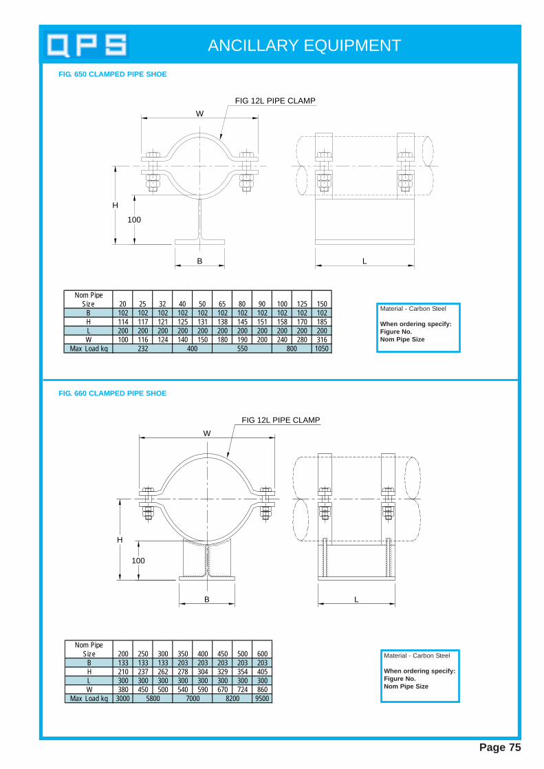
ANCILLARY EQUIPMENT
Page 75
W
100
H
B L
FIG 12L PIPE CLAMP
Material - Carbon Steel
When ordering specify:Figure No.Nom Pipe Size
FIG 12L PIPE CLAMP
W
H
100
B L
Material - Carbon Steel
When ordering specify:Figure No.Nom Pipe Size
FIG. 650 CLAMPED PIPE SHOE
FIG. 660 CLAMPED PIPE SHOE
Nom PipeSize 20 25 32 40 50 65 80 90 100 125 150
B 102 102 102 102 102 102 102 102 102 102 102H 114 117 121 125 131 138 145 151 158 170 185L 200 200 200 200 200 200 200 200 200 200 200W 100 116 124 140 150 180 190 200 240 280 316
Max Load kg 1050800232 400 550
Nom PipeSize 200 250 300 350 400 450 500 600
B 133 133 133 203 203 203 203 203H 210 237 262 278 304 329 354 405L 300 300 300 300 300 300 300 300W 380 450 500 540 590 670 724 860
Max Load kg 3000 95005800 7000 8200
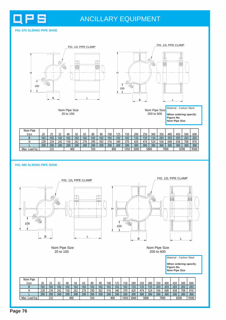
ANCILLARY EQUIPMENT
Page 76
20 to 150Nom Pipe Size Nom Pipe Size
200 to 600
FIG. 12L PIPE CLAMPFIG. 12L PIPE CLAMP
B L
100
H
100
H
B L
Material - Carbon Steel
When ordering specify:Figure No.Nom Pipe Size
FIG. 670 SLIDING PIPE SHOE
Nom Pipe Size20 to 150
Nom Pipe Size200 to 600
H
100
B LB L
100
H
FIG. 12L PIPE CLAMPFIG. 12L PIPE CLAMP
Material - Carbon Steel
When ordering specify:Figure No.Nom Pipe Size
FIG. 680 SLIDING PIPE SHOE
Nom PipeSize 20 25 32 40 50 65 80 90 100 125 150 200 250 300 350 400 450 500 600
B 102 102 102 102 102 102 102 102 102 102 102 133 133 133 203 203 203 203 203H 228 234 242 150 262 276 290 302 316 340 370 420 474 524 556 608 658 708 810L 200 200 200 200 200 200 200 200 200 200 200 300 300 300 300 300 300 300 300
Max Load kg 1050 3000 95005800 7000 8200232 400 550 800

ANCILLARY EQUIPMENT
Page 77
Nom Pipe Pipe MaxSize O/D B C H L Load kg25 33.7 102 50 117 150 45032 42.4 102 50 121 150 45040 48.3 102 50 124 150 45050 60.3 102 50 130 150 45065 76.1 102 50 138 150 45080 88.9 102 50 144 150 45090 101.6 102 50 151 150 450100 114.3 102 65 157 150 450125 139.7 102 65 170 150 450150 168.3 102 65 184 150 450200 219.1 133 80 210 200 2900250 273.0 133 80 237 200 2900300 323.9 133 80 262 200 2900350 355.6 203 80 278 250 6500400 406.4 203 80 303 250 6500450 457.2 254 80 329 250 7900500 508.0 305 90 354 300 7900550 558.8 305 90 379 300 8700600 609.6 305 90 405 300 9200
Material - Carbon Steel
When ordering specify:Figure No.Nom Pipe Size
Nom Pipe Pipe MaxSize O/D B H L Load kg25 33.7 102 117 150 45032 42.4 102 121 150 45040 48.3 102 124 150 45050 60.3 102 130 150 45065 76.1 102 138 150 45080 88.9 102 144 150 45090 101.6 102 151 150 450100 114.3 102 157 150 450125 139.7 102 170 150 450150 168.3 102 184 150 450200 219.1 133 210 200 2900250 273.0 133 237 200 2900300 323.9 133 262 200 2900350 355.6 203 278 250 6500400 406.4 203 303 250 6500450 457.2 254 329 250 7900500 508.0 305 354 300 7900550 558.8 305 379 300 8700600 609.6 305 405 300 8700
Material - Carbon Steel
When ordering specify:Figure No.Nom Pipe Size
FIG. 645 SLIDING SUPPORT (WELDED)
FIG. 646 SLIDING SUPPORTS WITH GUIDES (WELDED)
UP TO 150NB
200NB AND ABOVE
UP TO 150NB
200NB AND ABOVE
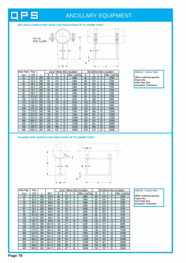
ANCILLARY EQUIPMENT
Page 78
H
B
G
L
G
G
W
T
H
B
G
L
G
G
FIG 12L PIPE CLAMP
Nom Pipe PipeSize O/D L B H G Max Load kg B H G Max Load kg25 33.7 200 60 137 6 2400 60 237 8 370032 42.4 200 60 141 6 2400 60 241 8 370040 48.3 200 60 147 6 2400 60 247 8 370050 60.3 200 60 153 6 2400 60 253 8 370065 76.1 200 60 161 6 2400 60 261 8 370080 88.9 200 60 167 6 2400 60 267 8 370090 101.6 200 60 174 6 2400 60 274 8 3700100 114.3 200 60 180 6 2650 60 280 8 3900125 139.7 300 120 193 10 4100 120 293 12 6150150 168.3 300 120 211 10 5200 120 311 12 8400200 219.1 300 120 237 10 5200 120 337 12 8400250 273.0 300 180 266 12 7300 180 366 16 13500300 323.9 300 180 291 12 7300 180 391 16 13500350 355.6 300 220 307 16 12000 220 407 20 15500400 406.4 300 230 332 16 12000 250 432 20 16500450 457.2 300 250 361 16 15300 250 461 20 18000500 508.0 300 280 386 16 16300 300 486 20 20400600 609.6 300 330 437 20 18000 350 537 25 23000
Up to 100mm thick insulation 100-200mm thick insulation
Nom Pipe PipeSize O/D L Wx T B H G Max Load kg B H G Max Load kg25 33.7 200 25x 3 60 137 6 2400 60 237 8 370032 42.4 200 25x 3 60 141 6 2400 60 241 8 370040 48.3 200 30x 6 60 147 6 2400 60 247 8 370050 60.3 200 30x 6 60 153 6 2400 60 253 8 370065 76.1 200 30x 6 60 161 6 2400 60 261 8 370080 88.9 200 30x 6 60 167 6 2400 60 267 8 370090 101.6 200 30x 6 60 174 6 2400 60 274 8 3700100 114.3 200 40x 6 60 180 6 2650 60 280 8 3900125 136.7 300 40x 6 60 191 10 4100 120 291 12 6150150 168.3 300 40x 10 120 211 10 5200 120 311 12 8400200 219.1 300 50x 12 120 237 10 5200 120 337 12 8400250 273.0 300 50x 12 180 266 12 7300 180 366 16 13500300 323.9 300 50x 12 180 291 12 7300 180 391 16 13500350 355.6 300 65x 12 220 307 16 12000 220 407 20 15500400 406.4 300 65x 12 230 332 16 12000 250 432 20 16500450 457.0 300 65x 15 250 361 16 15300 250 461 20 18000500 508.0 300 65x 15 280 386 16 16300 300 486 20 20400600 609.0 300 80x 15 330 437 20 18000 350 537 25 23000
Up to 100mm thick insulation 100-200mm thick insulation Material - Carbon Steel
When ordering specify:Figure No.Nom Pipe SizeInsulation Thickness
Material - Carbon Steel
When ordering specify:Figure No.Nom Pipe SizeInsulation Thickness
FIG.660SI PIPE SADDLE FOR INSULA TION UP TO 200MM THICK
FIG. 660I CLAMPED PIPE SHOE FOR INSULA TION UP TO 200MM THICK
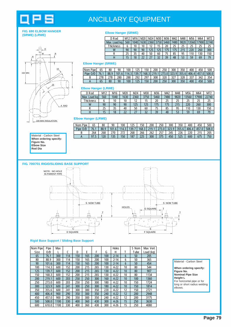
ANCILLARY EQUIPMENT
Page 79
FIG. 690 ELBOW HANGER(SRWE) (LRWE)
D Rod M12 M16 M20 M24 M30 M36 M42 M48 M56 M64 M72Max Load kg 560 1040 1630 2360 3750 5460 7480 9820 13560 17900 22740
Thickness 6 10 10 12 15 20 25 25 25 25 25W 90 90 90 125 125 175 175 215 220 260 300R 25 35 40 50 60 75 85 95 110 130 150H 15 18 22 27 32 39 48 53 59 69 79
Nom Pipe 65 80 90 100 125 150 200 250 300 350 400 450 500Pipe O/D 76.1 88.9 101.6 114.3 139.7 168.3 219.1 273.0 323.9 355.6 406.4 457.0 508.0
B 278 278 280 288 292 297 308 320 327 328 337 342 354A 65 80 90 100 125 150 200 250 300 350 400 450 500
D Rod M12 M16 M20 M24 M30 M36 M42 M48 M56 M64 M72Max Load kg 560 1040 1630 2360 3750 5460 7480 9820 13560 17900 22740
Thickness 6 10 10 12 15 20 25 25 25 25 25W 90 90 90 125 125 175 175 215 220 260 300R 25 35 40 50 60 75 85 95 110 130 150H 15 18 22 27 32 39 48 53 59 69 79
Nom Pipe 65 80 90 100 125 150 200 250 300 350 400 450 500Pipe O/D 76.1 88.9 101.6 114.3 139.7 168.3 219.1 273.0 323.9 355.6 406.4 457.0 508.0
B 264 268 270 272 268 266 262 257 245 226 220 215 205A 97.5 120 135 150 187 225 300 375 450 525 600 675 750
H
R
10
25
150 MINB
W
100 MAX INSULATION
D
A RAD
Material - Carbon SteelWhen ordering specify:Figure No.Elbow SizeRod Dia
Elbow Hanger (SR WE)
Elbow Hanger (SR WE)
Elbow Hanger (LR WE)
Elbow Hanger (LR WE)
C
D SQUARE
S NOM TUBE
NOTE : NO HOLEIN PARENT PIPE
T
S NOM TUBE
T
F SQUAREE
TG SQUAREL
HOLES
Nom Pipe Pipe Max Holes S Nom Max VertSize O/D L C D E F G H T Tube Load (kg)65 76.1 300 114 150 165 200 100 2-14 6 50 20580 88.9 300 114 150 165 200 100 2-14 6 50 36590 101.6 300 114 150 165 200 100 2-14 6 50 454
100 114.3 600 152 200 215 265 130 4-22 10 80 544125 139.7 600 152 200 215 265 130 4-22 10 80 907150 168.3 600 152 200 215 265 130 4-22 10 80 1134200 219.1 600 203 250 250 300 160 4-22 10 100 1360250 273.0 600 203 250 250 300 180 4-22 10 150 1724300 323.9 600 241 300 250 300 180 4-22 10 150 1814350 355.6 600 241 300 300 350 220 4-22 12 150 2721400 406.4 900 290 350 300 350 240 4-22 12 200 2948450 457.0 900 290 350 300 350 240 4-22 12 200 3175500 508.0 1100 330 400 360 430 300 4-26 15 250 3630600 610.0 1100 330 400 360 430 300 4-26 15 250 4080
Rigid Base Support / Sliding Base Support
FIG. 700/701 RIGID/SLIDING BASE SUPPORT
Material - Carbon Steel
When ordering specify:Figure No.Nominal Pipe SizeHeight LFor horizontal pipe or forlong or short radius weldingelbows.

Page 80
NOTES
BS 3974Pipe Support s
Section 4

Section 4 of this catalogue has been compiled with the kind permission of theBritish Standard Institution. All data has been taken from BS 3974 Part 1 (1974),Part 2 (1978) and Part 3 (1980). Q.P.S. reserve the right to alter specifications inline with any updates by the relevant British Standards.
Schedule of materials
Material referenceComponent Material BS no. Designation
(a) Pipe clipsClips Range A Carbon steel 4360 Grade 43A
Range B 1501: Part 1 151 or 161: grade 430B
Range D1, D1(M), D2 Alloy steel 1501: Part 2 620 grade 27BRange D3, D3(M) 1501: Part 2 622 grade 515B
All bolts and Range A, B Carbon steel 4190 Grade 4, 6studbolts
Range D1, D1(M), D2 Alloy steel 4882 661 grade B16Range D3, D3(M) 4882 1% Cr Mo V boron grade B16A
All nuts Range A, B Carbon steel 4190 Grade 4
Range D1, D1(M), D2 Alloy steel 4882 240 grade 4Range D3, D3(M) 4882 621 grade 7
Distance-pieces All ranges Carbon steel 1387 Medium or heavy
(b) U-strapsStrap Range D1, D2 Alloy steel 1501: Part 2 620 grade 27B
Range D3 1501: Part 2 622 grade 515B
Steady plate Range D1, D2, D3 Alloy steel 1501: Part 2 620 grade 27A or 27B
Yoke, end and Ranges D1, D2, D3 Carbon steel 4360 Grade 43Ahanger plates
All bolts Ranges D1, D2, D3 Carbon steel 3692 Grade 8.8All nuts 3692 Grade 8
(c) Riser ClampsClamp Range A Carbon steel 4360 Grade 43A
Range B, C 1501: Part 1 151 or 161: grade 430BClamp Range D1, D2 Alloy steel 1501: Part 2 620 grade 27Band gusset Range D3 1501: Part 2 622 grade 515B
All bolts Range A, B Carbon steel 4190 Grade 4.6Range C 3692 Grade 8.8Range D1, D2 Alloy steel 4882 661 grade B16Range D3 4882 1% Cr Mo V boron grade 816A
All nuts Range A, B Carbon steel 4190 240 grade 4Range C 3692 Grade 8Range D1, D2 Alloy steel 4882 240 grade 4Range D3 4882 621 grade 7
Distance-pieces Range A, B Carbon steel 1387 Medium or heavyRange C Alloy steel 1775 HFS13 or HFW13Range D1, D2 Carbon steel 1387 Medium or heavyRange D3 Alloy steel 3604 620
(d) Sling rods All componentsRods All ranges Carbon steel 4360 Grade 43ANuts All ranges 4190 Grade 4 or 6
(e) Pipe overstraps Carbon steel 4360 Grade 43Aand bolts
Low temperature see table 12steel in section three
(f) Pipe overstraps Copper alloy 2870 CZ 110and hookstraps
Stainless steel 1449: Part 2 17% min. Cr content
(g) Lining Lead sheet 1178 —materials forsteel pipe clips Copper/copper 2870 CZ 110when used on alloy sheetcopper/copperalloy tubes Compressed fibre — —
BS 3974 PIPE SUPPORTS
Page 81
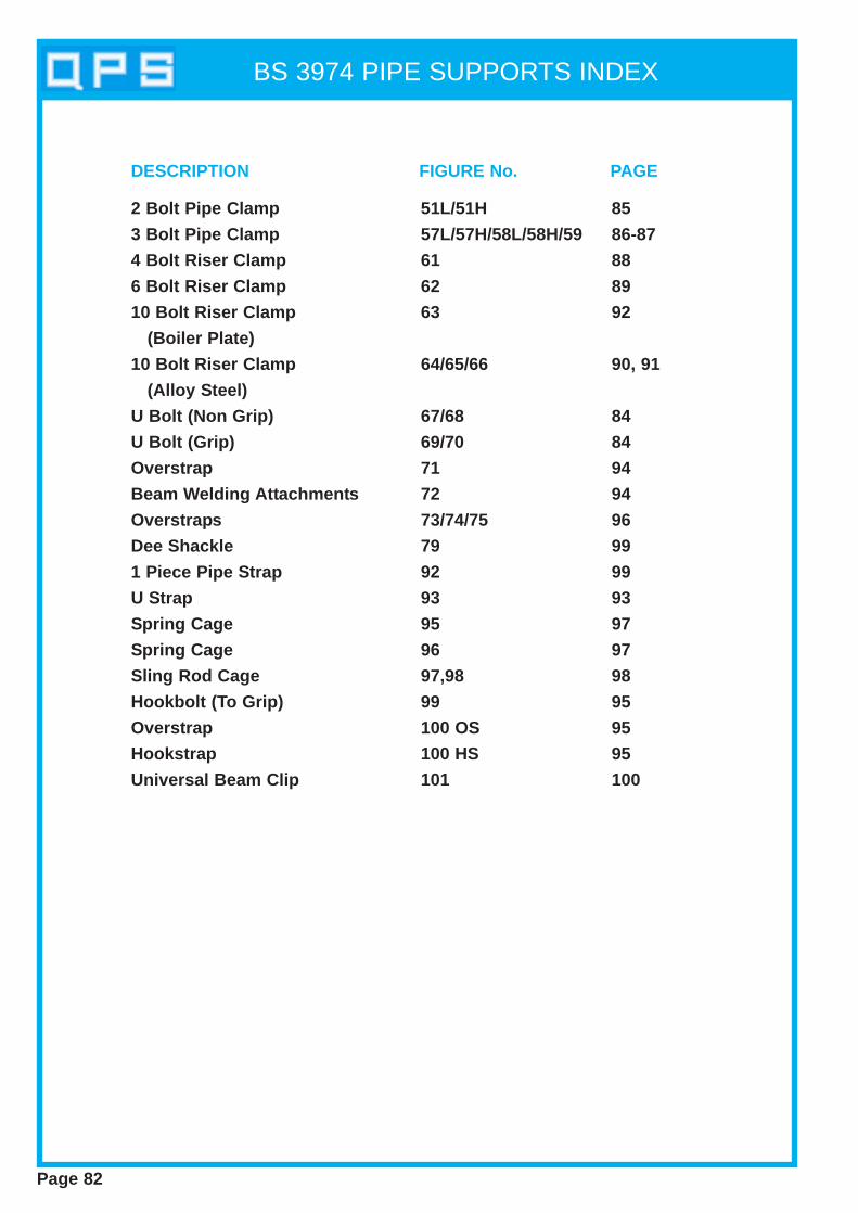
BS 3974 PIPE SUPPORTS INDEX
Page 82
2 Bolt Pipe Clamp
3 Bolt Pipe Clamp
4 Bolt Riser Clamp
6 Bolt Riser Clamp
10 Bolt Riser Clamp
(Boiler Plate)
10 Bolt Riser Clamp
(Alloy Steel)
U Bolt (Non Grip)
U Bolt (Grip)
Overstrap
Beam Welding Attachments
Overstraps
Dee Shackle
1 Piece Pipe Strap
U Strap
Spring Cage
Spring Cage
Sling Rod Cage
Hookbolt (To Grip)
Overstrap
Hookstrap
Universal Beam Clip
51L/51H
57L/57H/58L/58H/59
61
62
63
64/65/66
67/68
69/70
71
72
73/74/75
79
92
93
95
96
97,98
99
100 OS
100 HS
101
85
86-87
88
89
92
90, 91
84
84
94
94
96
99
99
93
97
97
98
95
95
95
100
DESCRIPTION FIGURE No. PAGE
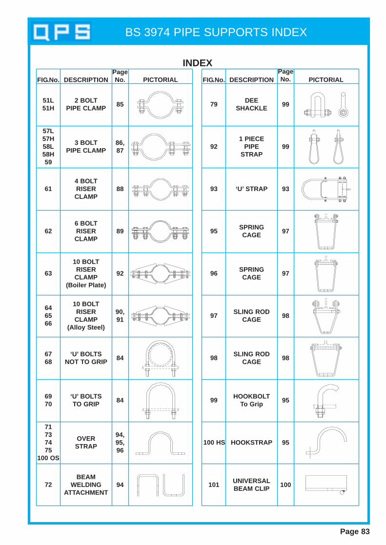
???????
BS 3974 PIPE SUPPORTS INDEX
INDEX
FIG.No. DESCRIPTIONPageNo. PICTORIAL FIG.No. DESCRIPTION
PageNo. PICTORIAL
51L51H
57L57H58L58H59
61
62
63
646566
6768
6970
71737475
100 OS
72
79
92
93
95
96
97
98
99
100 HS
101
2 BOLTPIPE CLAMP
3 BOLTPIPE CLAMP
4 BOLTRISERCLAMP
6 BOLTRISERCLAMP
10 BOLTRISERCLAMP
(Boiler Plate)
10 BOLTRISERCLAMP
(Alloy Steel)
‘U’ BOLTSNOT TO GRIP
‘U’ BOLTSTO GRIP
OVERSTRAP
BEAMWELDING
ATTACHMENT
DEESHACKLE
1 PIECEPIPE
STRAP
‘U’ STRAP
SPRINGCAGE
SPRINGCAGE
SLING RODCAGE
SLING RODCAGE
HOOKBOLTTo Grip
HOOKSTRAP
UNIVERSALBEAM CLIP
85
86,87
88
89
92
90,91
84
84
94,95,96
94
99
99
93
97
97
98
98
95
95
100
Page 83

BS 3974 PIPE SUPPORTS
Page 84
Nom pipe Pipe A N M K SSize O.D. Dia Max .15 21.3 8 40 45 25 1020 26.9 8 45 55 30 1025 33.7 8 50 60 30 1032 42.4 8 60 70 30 1040 48.3 10 65 85 40 1650 60.3 10 80 100 40 1665 76.1 12 95 120 50 1980 88.9 16 110 140 55 19
100 114.3 16 140 165 55 19125 139.7 16 165 190 55 19150 168.3 20 195 225 65 19175 193.7 20 220 250 65 19200 219.1 20 250 275 65 19225 244.5 20 275 300 65 19250 273.0 20 305 335 75 22300 323.9 20 355 385 75 22350 355.6 24 390 425 80 22400 406.4 24 440 475 80 22450 457.0 24 495 525 80 22500 508.0 24 545 575 80 22550 559.0 24 595 625 80 22600 610.0 24 645 675 80 22
Nom pipe Pipe A N M K SSize O.D. Dia Max .80 98 16 120 150 55 19
*100 118 16 140 165 55 19*150 170 20 195 225 65 19*200 222 20 250 275 65 19*250 274 20 305 335 75 22*300 326 20 355 385 75 22350 378 24 410 450 80 22400 429 24 465 500 80 22450 480 24 520 550 80 22500 532 24 570 600 80 22600 635 24 670 700 80 22
FIG. 68 Cast Iron Pipes
Dimensions of U-Bolts (not to grip pipe)All dimensions are in millimetres
Material - Carbon SteelWhen ordering specify:Figure No.Nominal pipe sizeFinish
*These U-bolts are identical with the equivalent sizes for steel pipe.
Nom pipe Pipe A N M K SSize O/D Dia Max15 21.3 8 30 50 25 720 26.9 8 35 60 25 1025 33.7 8 45 65 25 1032 42.4 8 55 75 25 1040 48.3 10 60 90 35 1650 60.3 10 75 100 35 1665 76.1 12 90 130 45 1980 88.9 16 105 150 50 19
100 114.3 16 135 175 50 19125 139.7 16 160 200 50 19150 168.3 20 190 235 55 19175 193.7 20 215 260 55 19200 219.1 20 245 295 55 19225 244.5 20 270 310 55 22250 273.0 20 300 350 60 22300 323.9 20 350 400 60 22350 355.6 24 385 440 65 22400 406.4 24 435 500 65 22450 457.0 24 485 540 70 22500 508.0 24 540 600 70 22550 559.0 24 590 650 70 22600 610.0 24 640 700 70 22
Nom pipe Pipe A N M K SSize O/D Dia Max80 98 16 115 160 50 19
*100 118 16 135 175 50 19*150 170 20 190 235 55 19*200 222 20 245 295 55 19*250 274 20 300 350 60 22*300 326 20 350 400 60 22350 378 24 405 460 65 22400 429 24 455 520 65 22450 482 24 505 560 70 22500 532 24 560 620 70 22600 635 24 660 720 70 22
Dimensions of U-Bolts (to grip pipe)All dimensions are in millimetres
FIG. 69 Steel Pipes
FIG. 70 Cast Iron Pipes
*These U-bolts are identical with the equivalent sizes for steel pipe.
FIG. 69/70 U-BOLT TO GRIPMaterial - Carbon Steel.When ordering specify:Figure NoNominal Pipe SizeFinish
FIG. 67 Steel Pipes
FIG. 67/68 U-BOLT NOT TO GRIP
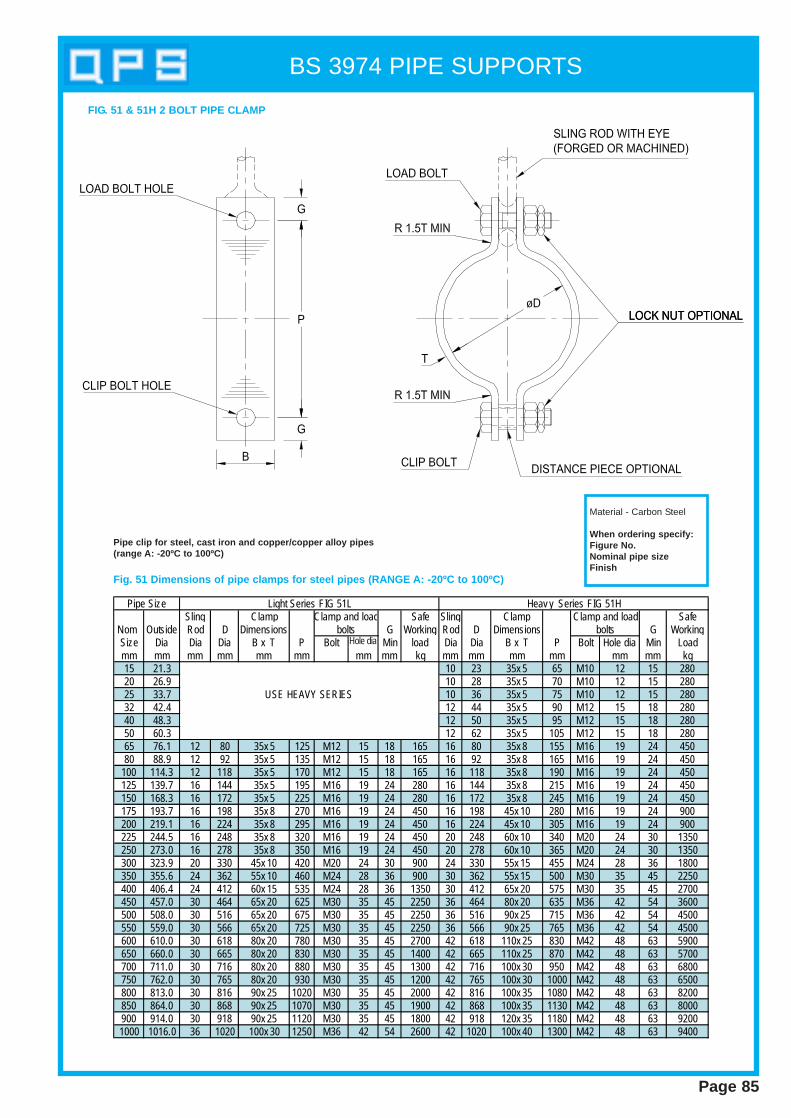
BS 3974 PIPE SUPPORTS
Page 85
FIG. 51 & 51H 2 BOLT PIPE CLAMP
Sling Clamp Safe Sling Clamp SafeNom Outside Rod D Dimensions G Working Rod D Dimensions G WorkingSize Dia Dia Dia B x T P Bolt Hole dia Min load Dia Dia B x T P Bolt Hole dia Min Loadmm mm mm mm mm mm mm mm kg mm mm mm mm mm mm kg15 21.3 10 23 35x 5 65 M10 12 15 28020 26.9 10 28 35x 5 70 M10 12 15 28025 33.7 10 36 35x 5 75 M10 12 15 28032 42.4 12 44 35x 5 90 M12 15 18 28040 48.3 12 50 35x 5 95 M12 15 18 28050 60.3 12 62 35x 5 105 M12 15 18 28065 76.1 12 80 35x 5 125 M12 15 18 165 16 80 35x 8 155 M16 19 24 45080 88.9 12 92 35x 5 135 M12 15 18 165 16 92 35x 8 165 M16 19 24 450
100 114.3 12 118 35x 5 170 M12 15 18 165 16 118 35x 8 190 M16 19 24 450125 139.7 16 144 35x 5 195 M16 19 24 280 16 144 35x 8 215 M16 19 24 450150 168.3 16 172 35x 5 225 M16 19 24 280 16 172 35x 8 245 M16 19 24 450175 193.7 16 198 35x 8 270 M16 19 24 450 16 198 45x 10 280 M16 19 24 900200 219.1 16 224 35x 8 295 M16 19 24 450 16 224 45x 10 305 M16 19 24 900225 244.5 16 248 35x 8 320 M16 19 24 450 20 248 60x 10 340 M20 24 30 1350250 273.0 16 278 35x 8 350 M16 19 24 450 20 278 60x 10 365 M20 24 30 1350300 323.9 20 330 45x 10 420 M20 24 30 900 24 330 55x 15 455 M24 28 36 1800350 355.6 24 362 55x 10 460 M24 28 36 900 30 362 55x 15 500 M30 35 45 2250400 406.4 24 412 60x 15 535 M24 28 36 1350 30 412 65x 20 575 M30 35 45 2700450 457.0 30 464 65x 20 625 M30 35 45 2250 36 464 80x 20 635 M36 42 54 3600500 508.0 30 516 65x 20 675 M30 35 45 2250 36 516 90x 25 715 M36 42 54 4500550 559.0 30 566 65x 20 725 M30 35 45 2250 36 566 90x 25 765 M36 42 54 4500600 610.0 30 618 80x 20 780 M30 35 45 2700 42 618 110x 25 830 M42 48 63 5900650 660.0 30 665 80x 20 830 M30 35 45 1400 42 665 110x 25 870 M42 48 63 5700700 711.0 30 716 80x 20 880 M30 35 45 1300 42 716 100x 30 950 M42 48 63 6800750 762.0 30 765 80x 20 930 M30 35 45 1200 42 765 100x 30 1000 M42 48 63 6500800 813.0 30 816 90x 25 1020 M30 35 45 2000 42 816 100x 35 1080 M42 48 63 8200850 864.0 30 868 90x 25 1070 M30 35 45 1900 42 868 100x 35 1130 M42 48 63 8000900 914.0 30 918 90x 25 1120 M30 35 45 1800 42 918 120x 35 1180 M42 48 63 92001000 1016.0 36 1020 100x 30 1250 M36 42 54 2600 42 1020 100x 40 1300 M42 48 63 9400
USE HEAVY SERIES
Clamp and loadbolts
Clamp and loadbolts
Pipe Size Light Series FIG 51L Heav y Series FIG 51H
Fig. 51 Dimensions of pipe clamp s for steel pipes (RANGE A: -20ºC to 100ºC)
Pipe clip for steel, cast iron and copper/copper alloy pipes(range A: -20ºC to 100ºC)
Material - Carbon Steel
When ordering specify:Figure No.Nominal pipe sizeFinish
Hole dia
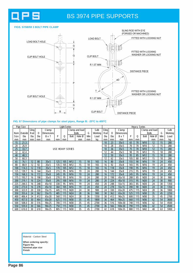
BS 3974 PIPE SUPPORTS
Page 86
Sling Clamp Safe Sling Clamp SafeNom Outside Rod D Dimensions G Working Rod D Dimensions G WorkingSize Dia Dia Dia B x T P Q Bolt Hole Ø Min Load Dia Dia B x T P Q Bolt Hole Ø Min Loadmm mm mm mm mm mm mm mm mm kg mm mm mm mm mm mm mm kg15 21.3 10 23 35x 5 65 70 M10 12 15 28020 26.9 10 28 35x 5 70 70 M10 12 15 28025 33.7 10 36 35x 5 75 70 M10 12 15 28032 42.4 12 44 35x 5 90 70 M12 15 18 28040 48.3 12 50 35x 5 95 85 M12 15 18 28050 60.3 12 62 35x 5 105 80 M12 15 18 28065 76.1 12 80 35x 5 125 105 M12 15 18 165 16 80 35x 8 155 90 M16 19 24 45080 88.9 12 92 35x 5 135 105 M12 15 18 165 16 92 35x 8 165 95 M16 19 24 450100 114.3 12 118 35x 5 170 105 M12 15 18 165 16 118 35x 8 190 95 M16 19 24 450125 139.7 16 144 35x 8 215 95 M16 19 24 280 16 144 35x 8 215 95 M16 19 24 450150 168.3 16 172 35x 8 245 95 M16 19 24 280 16 172 35x 8 245 95 M16 19 24 450175 193.7 16 198 35x 8 270 95 M16 19 24 280 20 198 45x 10 288 85 M20 24 30 900200 219.1 16 224 35x 8 295 100 M16 19 24 280 20 224 45x 10 315 95 M20 24 30 900225 244.5 16 248 45x 10 330 95 M16 19 24 450 20 248 55x 15 365 85 M20 24 30 1350250 273.0 16 278 45x 10 360 105 M16 19 24 450 20 278 55x 15 390 90 M20 24 30 1350300 323.9 20 330 55x 15 445 115 M20 24 30 900 24 330 65x 20 475 115 M24 28 36 1800350 355.6 24 362 55x 15 485 115 M24 28 36 900 30 362 65x 20 525 115 M30 35 45 2250400 406.4 24 412 65x 20 560 115 M24 28 36 1350 30 412 90x 25 600 115 M30 35 45 2700450 457.0 30 464 65x 20 625 115 M30 35 45 1800 36 464 90x 25 660 115 M36 42 54 3600500 508.0 30 516 90x 25 700 115 M30 35 45 2700 36 516 100x 30 740 115 M36 42 54 4500550 559.0 30 566 90x 25 750 115 M30 35 45 2700 36 566 100x 30 790 115 M36 42 54 4500600 610.0 30 618 90x 25 805 115 M30 35 45 2700 42 618 100x 35 880 115 M42 48 63 5900
USE HEAVY SERIES
Pipe Size
BoltsBoltsClamp and load Clamp and load
Light Series Heav y Series
FIG. 57 Dimensions of pipe clamp s for steel pipes, Range B: -20ºC to 400ºC
Material - Carbon Steel
When ordering specify:Figure No.Nominal pipe sizeFinish
FIGS. 57/58/59 3 BOLT PIPE CLAMP

BS 3974 PIPE SUPPORTS
Page 87
Sling Clamp Safe Sling Clamp SafeNom Outside Rod D Dimensions Bolts G Working Rod D Dimensions Bolts G WorkingSize Dia Dia Dia B x T P Q Bolt Hole Ø Min Load Dia Dia B x T P Q Bolt Hole Ø Min Loadmm mm mm mm mm mm mm mm mm kg mm mm mm mm mm mm mm kg15 21.3 10 23 35x 5 65 70 M10 12 15 28020 26.9 10 28 35x 5 70 70 M10 12 15 28025 33.7 10 36 35x 5 75 70 M10 12 15 90 10 36 35x 8 95 60 M10 12 15 28032 42.4 12 44 35x 5 90 70 M12 15 15 90 12 44 35x 8 110 60 M12 15 18 28040 48.3 12 50 35x 5 95 85 M12 15 15 90 12 50 35x 8 115 75 M12 15 18 28050 60.3 12 62 35x 5 105 80 M12 15 15 90 12 62 35x 8 125 70 M12 15 18 28065 76.1 12 80 35x 8 145 95 M12 15 18 165 16 80 35x 8 155 90 M16 19 24 45080 88.9 12 92 35x 8 155 95 M12 15 18 165 16 92 35x 8 165 95 M16 19 24 450
100 114.3 12 118 35x 8 190 95 M12 15 18 165 16 118 45x 10 200 90 M16 19 24 450125 139.7 16 144 45x 10 225 90 M16 19 24 280 16 144 45x 10 225 90 M16 19 24 450150 168.3 16 172 45x 10 255 90 M16 19 24 280 16 172 45x 10 255 90 M16 19 24 450175 193.7 16 198 45x 10 280 90 M16 19 24 280 20 198 55x 15 315 75 M20 24 30 900200 219.1 16 224 45x 10 305 100 M16 19 24 280 20 224 55x 15 340 80 M20 24 30 900225 244.5 16 248 55x 15 350 85 M16 19 24 450 20 248 65x 20 390 70 M20 24 30 1350250 273.0 16 278 55x 15 385 95 M16 19 24 450 20 278 65x 20 415 80 M20 24 30 1350300 323.9 20 330 65x 20 470 115 M20 24 30 900 24 330 90x 25 505 115 M24 28 36 1800350 355.6 24 362 65x 20 510 115 M24 28 36 900 30 362 110x 25 550 115 M30 35 45 2250400 406.4 24 412 90x 25 585 115 M24 28 36 1350 30 412 120x 30 625 115 M30 35 45 2700450 457.0 30 464 110x 25 650 115 M30 35 45 1800 36 464 120x 35 710 115 M36 42 54 3600500 508.0 30 516 120x 30 725 115 M30 35 45 2250 36 516 110x 45 815 115 M36 42 54 4500550 559.0 30 566 120x 30 775 115 M30 35 45 2250 36 566 110x 45 865 115 M36 42 54 4500600 610.0 30 618 120x 35 855 115 M30 35 45 2700 42 618 130x 50 955 115 M42 48 63 5900
USE HEAVY SERIES
Pipe Size Light Series Heav y SeriesClamp and load Clamp and load
GNominal Outside Sling D P Q Bolt Bolt Min
Size Dia Rod Diameter Size HoleDiameter Dia
D1 D2&D3 D1 and D2 D315 21.3 12 23 40x 6 55x 6 85 65 M12 15 18 450 37520 26.9 12 28 40x 6 55x 6 90 65 M12 15 18 450 37525 33.7 12 36 40x 6 55x 6 105 65 M12 15 18 450 37532 42.4 12 44 40x 6 55x 6 105 65 M12 15 18 450 37540 48.3 16 50 50x 10 60x 10 115 75 M16 19 24 900 75050 60.3 16 62 50x 10 60x 10 130 75 M16 19 24 900 75065 76.1 16 80 50x 10 60x 10 155 75 M16 19 24 900 75080 88.9 16 92 50x 10 60x 10 165 100 M16 19 24 900 750100 114.3 16 118 60x 10 70x 12 195 100 M16 19 24 900 750125 139.7 20 144 70x 12 80x 12 235 100 M20 24 30 1350 1130150 168.3 24 172 70x 12 80x 15 275 100 M24 28 36 1800 1500175 193.7 24 198 80x 12 100x 20 325 100 M24 28 36 1800 1500200 219.1 24 224 80x 12 100x 20 360 100 M24 28 36 1800 1500225 244.5 24 248 110x 12 100x 20 385 100 M24 28 36 1800 1500250 273.0 24 276 110x 12 100x 25 435 100 M24 28 36 1800 1500300 323.9 30 330 100x 20 120x 25 500 115 M30 35 45 2700 2260
30 362 100x 20 120x 25 585 115 M30 35 45 2700 226042 362 140x 25 100x 40 585 115 M42 48 63 5900 495030 412 110x 20 140x 25 625 115 M30 35 45 2700 226042 412 140x 25 130x 40 625 115 M42 48 63 5900 495030 464 100x 25 140x 30 690 115 M30 35 45 3600 302042 464 120x 30 140x 40 690 115 M42 48 63 5900 495030 516 120x 25 160x 30 745 115 M30 35 45 3600 302042 516 130x 30 160x 40 745 115 M42 48 63 5900 495030 566 130x 25 180x 30 800 115 M30 35 45 3600 302042 566 150x 30 160x 40 800 115 M42 48 63 5900 495030 618 140x 25 200x 30 845 115 M30 35 45 3600 302042 618 160x 30 200x 40 845 115 M42 48 63 5900 4950
Safe WorkingLoad
400
450
500
Clamp Dimensions*
Sub RangesB x T
Pipe Clamp and load bolts
550
600
355.6
406.4
457.0
508.0
559.0
610.0
350
FIG. 59 Dimensions of alloy steel pipe clamp s for steel pipes.(range D: 20ºC to 570ºC) All dimensions are in millimetres
When ordering specify:Figure No.Nominal pipe sizeFinish
*Range D1 gives dimensions for pipe clamp s using BS1501 : 620 grade 27B (1% Cr , ½% Mo) material for use formaximum temperature of 510ºC.Ranges D2 and D3 give respectively , dimensions for pipe clip s using BS 1501 : 620 grade 27B (1% Cr , ½% Mo)material for use for maximum temperature of 540ºC and BS 1501 : 622 grade 31B ( 2¼% Cr , 1 % Mo) Material for useup to 570ºC
FIG. 58 Dimensions of pipe clamp s for steel pipes, Range C:400ºC to 470ºC
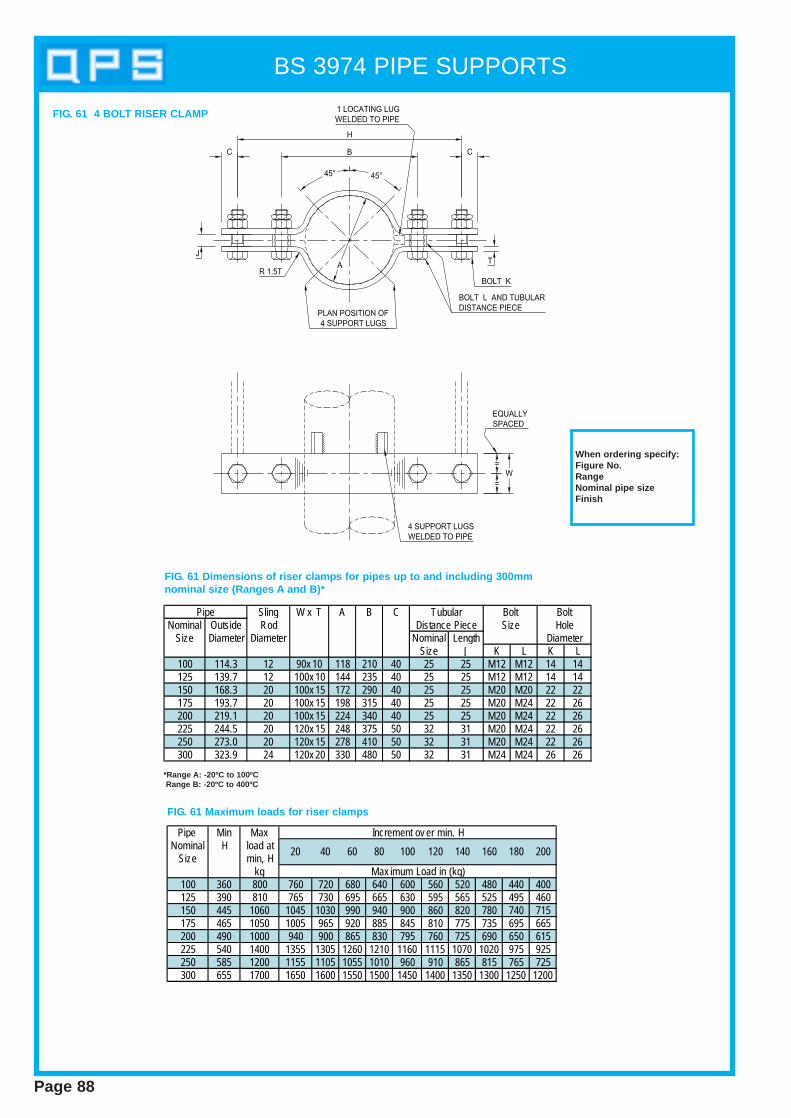
BS 3974 PIPE SUPPORTS
Page 88
Sling W x T A B CNominal Outside Rod
Size Diameter Diameter Nominal LengthSize J K L K L
100 114.3 12 90x 10 118 210 40 25 25 M12 M12 14 14125 139.7 12 100x 10 144 235 40 25 25 M12 M12 14 14150 168.3 20 100x 15 172 290 40 25 25 M20 M20 22 22175 193.7 20 100x 15 198 315 40 25 25 M20 M24 22 26200 219.1 20 100x 15 224 340 40 25 25 M20 M24 22 26225 244.5 20 120x 15 248 375 50 32 31 M20 M24 22 26250 273.0 20 120x 15 278 410 50 32 31 M20 M24 22 26300 323.9 24 120x 20 330 480 50 32 31 M24 M24 26 26
BoltHole
Pipe TubularDistance Piece
BoltSize
Diameter
Pipe Min MaxNominal H load at
Size min, Hkg
100 360 800 760 720 680 640 600 560 520 480 440 400125 390 810 765 730 695 665 630 595 565 525 495 460150 445 1060 1045 1030 990 940 900 860 820 780 740 715175 465 1050 1005 965 920 885 845 810 775 735 695 665200 490 1000 940 900 865 830 795 760 725 690 650 615225 540 1400 1355 1305 1260 1210 1160 1115 1070 1020 975 925250 585 1200 1155 1105 1055 1010 960 910 865 815 765 725300 655 1700 1650 1600 1550 1500 1450 1400 1350 1300 1250 1200
140 16020 40 60 80
Increment ov er min. H
Max imum Load in (kg)
180 200100 120
FIG. 61 4 BOLT RISER CLAMP
FIG. 61 Dimensions of riser clamp s for pipes up to and including 300mmnominal size (Ranges A and B)*
FIG. 61 Maximum loads for riser clamp s
When ordering specify:Figure No.RangeNominal pipe sizeFinish
*Range A: -20ºC to 100ºCRange B: -20ºC to 400ºC
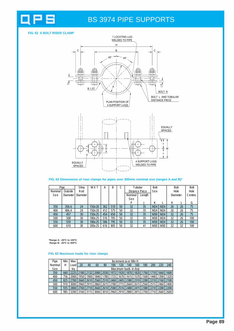
BS 3974 PIPE SUPPORTS
Page 89
Sling W X T A B C Bolt BoltNominal Outside Rod Size Hole
Size Diameter Diameter Nominal Length CentresSize
P J K L K L G350 356.6 24 150x 20 362 510 50 32 35 M24 M24 26 26 75400 406.4 24 150x 20 412 575 50 32 35 M24 M24 26 26 75450 457 30 150x 25 454 650 50 32 35 M30 M24 32 26 75500 508 30 180x 25 516 705 50 32 35 M30 M24 32 26 100550 559 30 180x 25 586 795 50 32 35 M30 M24 32 26 100600 610 30 200x 25 616 805 50 32 41 M30 M30 32 32 100
Pipe TubularDistance Piece
BoltHole
Diameter
FIG. 62 6 BOLT RISER CLAMP
FIG. 62 Dimensions of riser clamp s for pipes over 300mm nominal size (ranges A and B)*
*Range A: -20ºC to 100ºCRange B: -20ºC to 400ºC
Pipe Min MaxNominal H Load 20 40 60 80 100 120 140 160 180 200 220 240
Size kg350 660 2225 2180 2132 2080 2030 1972 1920 1870 1820 1760 1710 1660 1600400 756 2000 1950 1900 1840 1780 1725 1670 1615 1570 1500 1440 1390 1320450 825 2700 2660 2610 2560 2510 2460 2405 2380 2310 2280 2210 2160 2100500 910 3000 2960 2915 2860 2615 2780 2715 2660 2615 2560 2515 2460 2400550 935 2800 2760 2710 2660 2610 2580 2516 2480 2415 2380 2210 2280 2200600 985 3200 3160 3115 3060 3010 2960 2910 2880 2815 2760 2710 2660 2600
Increment ov er Min H
Max imum loads in (kg)
FIG. 62 Maximum loads for riser clamp s

BS 3974 PIPE SUPPORTS
Page 90
Sling SafeNominal Outside Rod W x T A B*Min Bolt Bolt D E F Bolt Bolt H J K L M N Working
Size Diameter Diameter Size Hole Size Hole LoadC Diameter G Diameter kg
200 219.1 24 130x 20 225 65 M24 26 36 36 1065 M16 18 458 205 65 50 485 40 2270225 244.5 24 130x 20 250 65 M24 26 36 36 1065 M16 18 508 180 65 60 485 40 2270250 273.0 24 155x 20 279 65 M24 26 36 36 1220 M16 18 508 255 80 60 560 40 2270300 323.9 30 155x 25 330 65 M30 33 45 45 1220 M20 22 560 230 80 75 560 40 3630
30 155x 25 362 65 M30 33 45 45 1220 M20 22 610 205 80 85 560 40 363042 205x 35 362 65 M42 45 63 63 1370 M24 26 610 280 105 85 635 50 726030 155x 25 413 65 M30 33 45 45 1370 M20 22 660 255 80 100 635 40 363042 205x 35 413 65 M42 45 63 63 1370 M24 26 660 255 105 100 635 50 726036 155x 35 470 65 M36 39 54 54 1370 M24 26 710 230 80 110 635 50 454042 205x 35 470 65 M42 45 63 63 1370 M24 26 710 230 105 110 635 50 726036 180x 35 521 65 M36 39 54 54 1525 M24 26 762 280 90 125 710 50 454042 230x 35 521 65 M42 45 63 63 1525 M24 26 762 280 115 125 710 50 726036 180x 35 572 65 M36 39 54 54 1525 M24 26 812 255 90 140 710 50 454042 230x 35 572 65 M42 45 63 63 1525 M24 26 812 255 115 140 710 50 726036 180x 35 622 65 M36 39 54 54 1525 M24 26 864 230 90 150 710 50 454042 255x 35 622 65 M42 45 63 63 1525 M24 26 864 230 130 150 710 50 7260
Pipe Load Bolt Clamp Bolt Gusset PlateClamp
550 559.0
600 610.0
450 457.0
500 508.0
350 355.6
400 406.4
FIG. 64 Dimensions of riser clamp s for steel pipes (Range D1: -20ºC to 510ºC)All dimensions are in millimetres
FIG. 64,65,66 10 BOLT RISER CLAMP
When ordering specify:Figure No.Nominal pipe sizeFinish
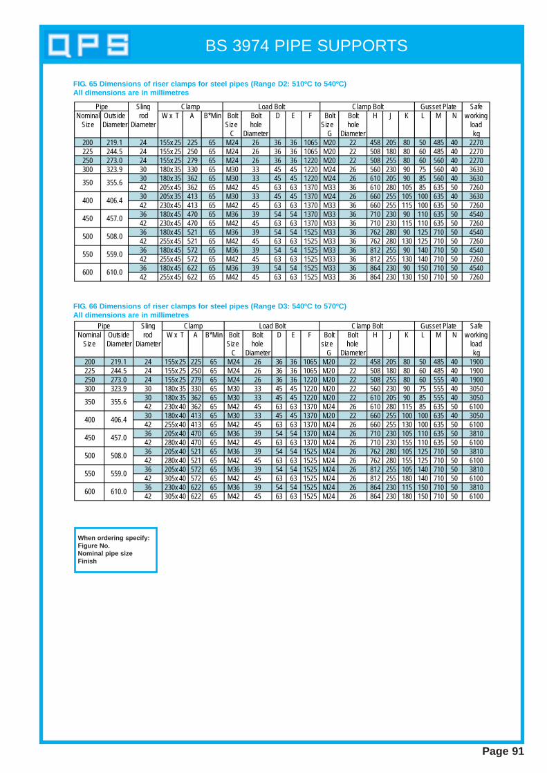
BS 3974 PIPE SUPPORTS
Page 91
Sling SafeNominal Outside rod W x T A B*Min Bolt Bolt D E F Bolt Bolt H J K L M N w orking
Size Diameter Diameter Size hole Size hole loadC Diameter G Diameter kg
200 219.1 24 155x 25 225 65 M24 26 36 36 1065 M20 22 458 205 80 50 485 40 2270225 244.5 24 155x 25 250 65 M24 26 36 36 1065 M20 22 508 180 80 60 485 40 2270250 273.0 24 155x 25 279 65 M24 26 36 36 1220 M20 22 508 255 80 60 560 40 2270300 323.9 30 180x 35 330 65 M30 33 45 45 1220 M24 26 560 230 90 75 560 40 3630
30 180x 35 362 65 M30 33 45 45 1220 M24 26 610 205 90 85 560 40 363042 205x 45 362 65 M42 45 63 63 1370 M33 36 610 280 105 85 635 50 726030 205x 35 413 65 M30 33 45 45 1370 M24 26 660 255 105 100 635 40 363042 230x 45 413 65 M42 45 63 63 1370 M33 36 660 255 115 100 635 50 726036 180x 45 470 65 M36 39 54 54 1370 M33 36 710 230 90 110 635 50 454042 230x 45 470 65 M42 45 63 63 1370 M33 36 710 230 115 110 635 50 726036 180x 45 521 65 M36 39 54 54 1525 M33 36 762 280 90 125 710 50 454042 255x 45 521 65 M42 45 63 63 1525 M33 36 762 280 130 125 710 50 726036 180x 45 572 65 M36 39 54 54 1525 M33 36 812 255 90 140 710 50 454042 255x 45 572 65 M42 45 63 63 1525 M33 36 812 255 130 140 710 50 726036 180x 45 622 65 M36 39 54 54 1525 M33 36 864 230 90 150 710 50 454042 255x 45 622 65 M42 45 63 63 1525 M33 36 864 230 130 150 710 50 7260
Gusset PlatePipe Clamp Load Bolt Clamp Bolt
350 355.6
400 406.4
450 457.0
500 508.0
550 559.0
600 610.0
FIG. 65 Dimensions of riser clamp s for steel pipes (Range D2: 510ºC to 540ºC)All dimensions are in millimetres
Sling SafeNominal Outside rod W x T A B*Min Bolt Bolt D E F Bolt Bolt H J K L M N w orking
Size Diameter Diameter Size hole size hole loadC Diameter G Diameter kg
200 219.1 24 155x 25 225 65 M24 26 36 36 1065 M20 22 458 205 80 50 485 40 1900225 244.5 24 155x 25 250 65 M24 26 36 36 1065 M20 22 508 180 80 60 485 40 1900250 273.0 24 155x 25 279 65 M24 26 36 36 1220 M20 22 508 255 80 60 555 40 1900300 323.9 30 180x 35 330 65 M30 33 45 45 1220 M20 22 560 230 90 75 555 40 3050
30 180x 35 362 65 M30 33 45 45 1220 M20 22 610 205 90 85 555 40 305042 230x 40 362 65 M42 45 63 63 1370 M24 26 610 280 115 85 635 50 610030 180x 40 413 65 M30 33 45 45 1370 M20 22 660 255 100 100 635 40 305042 255x 40 413 65 M42 45 63 63 1370 M24 26 660 255 130 100 635 50 610036 205x 40 470 65 M36 39 54 54 1370 M24 26 710 230 105 110 635 50 381042 280x 40 470 65 M42 45 63 63 1370 M24 26 710 230 155 110 635 50 610036 205x 40 521 65 M36 39 54 54 1525 M24 26 762 280 105 125 710 50 381042 280x 40 521 65 M42 45 63 63 1525 M24 26 762 280 155 125 710 50 610036 205x 40 572 65 M36 39 54 54 1525 M24 26 812 255 105 140 710 50 381042 305x 40 572 65 M42 45 63 63 1525 M24 26 812 255 180 140 710 50 610036 230x 40 622 65 M36 39 54 54 1525 M24 26 864 230 115 150 710 50 381042 305x 40 622 65 M42 45 63 63 1525 M24 26 864 230 180 150 710 50 6100
Gusset PlatePipe Clamp Load Bolt Clamp Bolt
350 355.6
400 406.4
450 457.0
500 508.0
550 559.0
600 610.0
FIG. 66 Dimensions of riser clamp s for steel pipes (Range D3: 540ºC to 570ºC)All dimensions are in millimetres
When ordering specify:Figure No.Nominal pipe sizeFinish
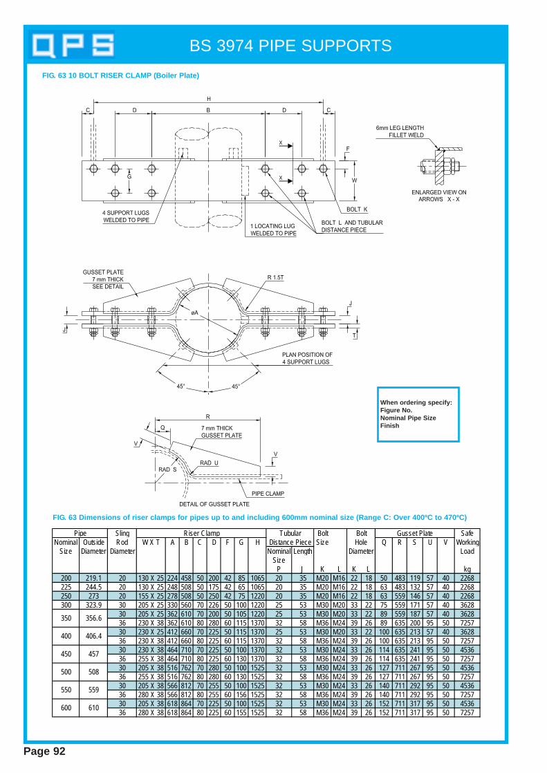
BS 3974 PIPE SUPPORTS
Page 92
Sling Bolt SafeNominal Outside Rod W X T A B C D F G H Size Q R S U V Working
Size Diameter Diameter Nominal Length LoadSize
P J K L K L kg200 219.1 20 130 X 25 224 458 50 200 42 85 1065 20 35 M20 M16 22 18 50 483 119 57 40 2268225 244.5 20 130 X 25 248 508 50 175 42 65 1065 20 35 M20 M16 22 18 63 483 132 57 40 2268250 273 20 155 X 25 278 508 50 250 42 75 1220 20 35 M20 M16 22 18 63 559 146 57 40 2268300 323.9 30 205 X 25 330 560 70 226 50 100 1220 25 53 M30 M20 33 22 75 559 171 57 40 3628
30 205 X 25 362 610 70 200 50 105 1220 25 53 M30 M20 33 22 89 559 187 57 40 362836 230 X 38 362 610 80 280 60 115 1370 32 58 M36 M24 39 26 89 635 200 95 50 725730 230 X 25 412 660 70 225 50 115 1370 25 53 M30 M20 33 22 100 635 213 57 40 362836 230 X 38 412 660 80 225 60 115 1370 32 58 M36 M24 39 26 100 635 213 95 50 725730 230 X 38 464 710 70 225 50 100 1370 32 53 M30 M24 33 26 114 635 241 95 50 453636 255 X 38 464 710 80 225 60 130 1370 32 58 M36 M24 39 26 114 635 241 95 50 725730 205 X 38 516 762 70 280 50 100 1525 32 53 M30 M24 33 26 127 711 267 95 50 453636 255 X 38 516 762 80 280 60 130 1525 32 58 M36 M24 39 26 127 711 267 95 50 725730 205 X 38 566 812 70 255 50 100 1525 32 53 M30 M24 33 26 140 711 292 95 50 453636 280 X 38 566 812 80 255 60 156 1525 32 58 M36 M24 39 26 140 711 292 95 50 725730 205 X 38 618 864 70 225 50 100 1525 32 53 M30 M24 33 26 152 711 317 95 50 453636 280 X 38 618 864 80 225 60 155 1525 32 58 M36 M24 39 26 152 711 317 95 50 7257
600 610
Pipe Riser Clamp
500 508
550 559
400 406.4
Gusset Plate
450 457
BoltHole
Diameter
350 356.6
TubularDistance Piece
FIG. 63 Dimensions of riser clamps for pipes up to and including 600mm nominal size (Range C: Over 400ºC to 470ºC)
FIG. 63 10 BOLT RISER CLAMP (Boiler Plate)
When ordering specify:Figure No.Nominal Pipe SizeFinish

BS 3974 PIPE SUPPORTS
Page 93
SlingNominal Outside Rod End Plate
Size Diameter Diameter D1 D2&D3 A B C D E F G H K L x M x T2 D1 and D3W x T1 W x T1 D2
kg kg200 219.1 24 80x 12 100x 20 112 470 224 184 40 30 36 50 26 152x 152x 15 1800 1500225 244.5 24 110x 12 100x 20 124 480 248 196 40 30 36 50 26 152x 152x 15 1800 1500250 273 24 110x 12 100x 25 138 490 276 210 40 30 36 50 26 152x 152x 15 1800 1500300 323.9 30 100x 20 120x 25 165 515 330 237 40 35 45 65 33 152x 152x 15 2700 2260
30 100x 20 120x 25 181 530 362 253 40 35 45 65 33 152x 152x 15 2700 226042 140x 25 100x 40 181 530 362 253 40 50 63 90 45 152x 152x 20 5900 495030 110x 20 140x 25 206 560 412 278 50 35 45 65 33 152x 152x 15 2700 226042 140x 25 130x 40 206 560 412 278 50 50 63 90 45 152x 152x 20 5900 495030 100x 25 140x 30 232 635 464 304 40 35 45 65 33 152x 152x 20 3600 302042 120x 30 140x 40 232 635 464 304 40 50 63 90 45 152x 152x 20 5900 495030 120x 25 160x 30 258 660 516 330 60 35 45 65 33 154x 161x 20 3600 302042 130x 30 160x 40 258 660 516 330 60 50 63 90 45 154x 161x 20 5900 495030 130x 25 180x 30 283 685 566 355 70 35 45 65 33 154x 161x 20 3600 302042 150x 30 160x 40 283 685 566 355 70 50 63 90 45 154x 161x 20 5900 495030 140x 25 200x 30 309 710 618 381 75 35 45 65 33 154x 161x 20 3600 302042 160x 30 200x 40 309 710 618 381 75 50 63 90 45 154x 161x 20 5900 4950
610600
550
355.6
406.4
457
508500
450
400
350
559
Safe WorkingLoad
U-PlatePipeSub-Ranges Hanger Plate
Yoke
FIG.93 Dimensions of alloy steel U-S traps for steel pipes (Range D:-20ºC to 570ºC)All dimensions are in millimetres.
Material - Carbon SteelWhen ordering specify:Figure No.Nominal Pipe SizeFinish
NOTE 1. This support is suit able only for nominally horizont al sections of pipe lines. When using this type of support consideration shall be given toproblems related to possible in-service damage to the pipe thermal insulation in the vicinity of the support.NOTE 2. Range D1 gives dimensions for pipe clip s using BS 1501: 620 grade 27B (1% Cr , ½% Mo) material for use for maximum temperature of 510ºC.
Ranges D2 and D3 give respectively , dimensions for pipe clip s using BS 1501 : 620 grade 27B (1% Cr , ½% Mo) material for use for maximum temperature of 540ºC and BS 1501: 622 grade 31B (2¼ % Cr , 1% Mo) material for use up to 570ºC.
NOTE 3. Asbestos free t ape or millboard may be placed between the pipe and the U-S trap. In such cases, the dimensions of the U-S trap shall beadjusted to ensure that it does not tighten on to the pipe.
FIG. 93 U-STRAP

BS 3974 PIPE SUPPORTS
Page 94
Nom SteelPipe Pipe Size Hole BoltSize O/D A B Wx T C R E Dia15 21.3 53 91 35x 5 10 11.5 12 1020 26.9 55 93 35x 5 13 14 12 1025 33.7 57 95 35x 5 16 18 12 1032 42.4 64 102 35x 8 20 22 15 1240 48.3 79 117 35x 8 23 25 15 1250 60.3 81 119 35x 8 29 31 15 1265 76.1 89 127 45x 10 36 40 19 1680 88.9 99 137 45x 10 43 46 19 16100 114.3 108 146 45x 10 55 59 19 16125 139.7 119 160 60x 10 68 72 24 20150 168.3 136 174 60x 10 82 86 24 20175 193.7 155 195 55x 15 95 99 24 20200 219.1 170 210 55x 15 107 112 24 20
Sling Material Hole Bolt or SafeRod size A C D Dia rod WorkingDia Bx T E Dia Load kg8 50x 6 75 40 50 14 12 230
10 50x 6 75 40 50 14 12 36012 50x 6 75 40 50 18 16 55016 75x 10 85 60 55 22 20 101020 75x 12 85 70 55 27 24 158024 100x 12 115 75 80 33 30 2280
1. Beam welding att achment sTwo types of beam welding attachments are specified:Type 1: Inverted U-shape attachmentType 2: U shaped attachment
2. Interchangeability . These attachments are interchangeable ifsupplied with all three holes drilled, as given in table 2.
FIG. 72 BEAM WELDING ATTACHMENT
All dimensions in millimetres
Material - Carbon SteelWhen ordering specify:Figure No.Nominal Pipe SizeFinish
Material - Carbon SteelWhen ordering specify:Figure No.SizeFinish
FIG 71 OVERSTRAP
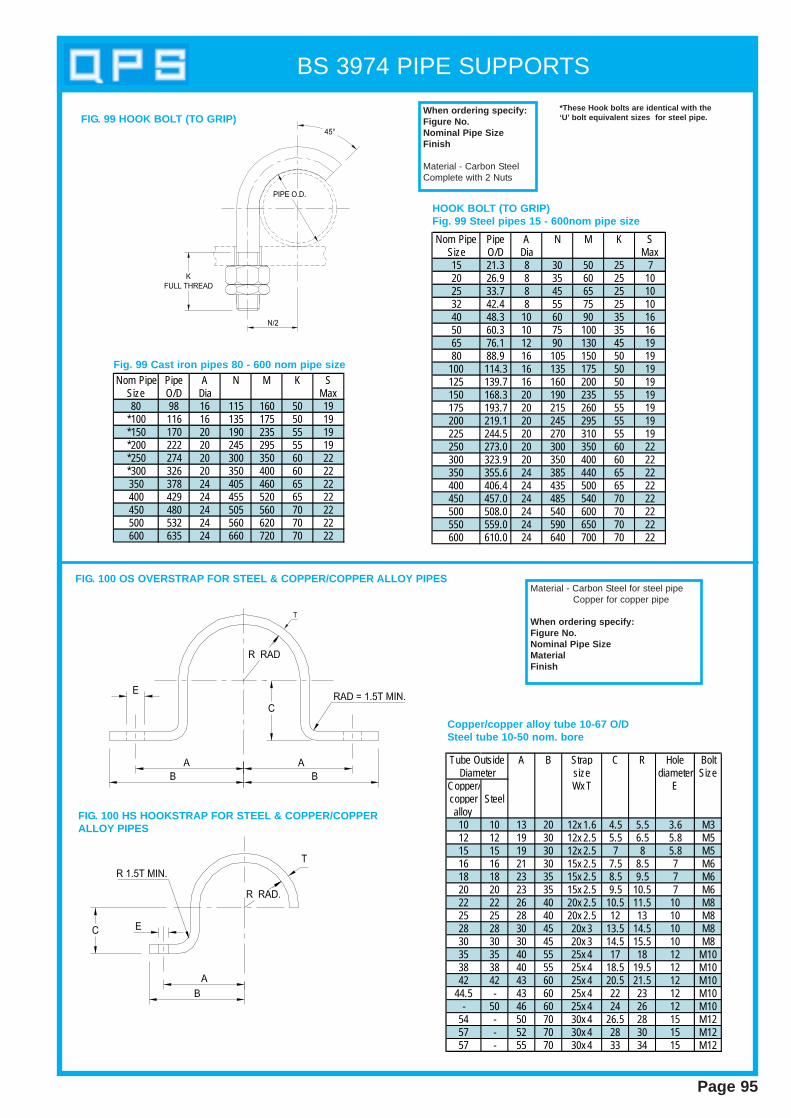
BS 3974 PIPE SUPPORTS
Page 95
FIG. 99 HOOK BOLT (TO GRIP)
Nom Pipe Pipe A N M K SSize O/D Dia Max80 98 16 115 160 50 19
*100 116 16 135 175 50 19*150 170 20 190 235 55 19*200 222 20 245 295 55 19*250 274 20 300 350 60 22*300 326 20 350 400 60 22350 378 24 405 460 65 22400 429 24 455 520 65 22450 480 24 505 560 70 22500 532 24 560 620 70 22600 635 24 660 720 70 22
Nom Pipe Pipe A N M K SSize O/D Dia Max15 21.3 8 30 50 25 720 26.9 8 35 60 25 1025 33.7 8 45 65 25 1032 42.4 8 55 75 25 1040 48.3 10 60 90 35 1650 60.3 10 75 100 35 1665 76.1 12 90 130 45 1980 88.9 16 105 150 50 19
100 114.3 16 135 175 50 19125 139.7 16 160 200 50 19150 168.3 20 190 235 55 19175 193.7 20 215 260 55 19200 219.1 20 245 295 55 19225 244.5 20 270 310 55 19250 273.0 20 300 350 60 22300 323.9 20 350 400 60 22350 355.6 24 385 440 65 22400 406.4 24 435 500 65 22450 457.0 24 485 540 70 22500 508.0 24 540 600 70 22550 559.0 24 590 650 70 22600 610.0 24 640 700 70 22
HOOK BOLT (TO GRIP)Fig. 99 Steel pipes 15 - 600nom pipe size
Fig. 99 Cast iron pipes 80 - 600 nom pipe size
When ordering specify:Figure No.Nominal Pipe SizeFinish
Material - Carbon SteelComplete with 2 Nuts
A B Strap C R Hole Boltsize diameter Size
Copper/ Wx T Ecopper Steelalloy10 10 13 20 12x 1.6 4.5 5.5 3.6 M312 12 19 30 12x 2.5 5.5 6.5 5.8 M515 15 19 30 12x 2.5 7 8 5.8 M516 16 21 30 15x 2.5 7.5 8.5 7 M618 18 23 35 15x 2.5 8.5 9.5 7 M620 20 23 35 15x 2.5 9.5 10.5 7 M622 22 26 40 20x 2.5 10.5 11.5 10 M825 25 28 40 20x 2.5 12 13 10 M828 28 30 45 20x 3 13.5 14.5 10 M830 30 30 45 20x 3 14.5 15.5 10 M835 35 40 55 25x 4 17 18 12 M1038 38 40 55 25x 4 18.5 19.5 12 M1042 42 43 60 25x 4 20.5 21.5 12 M10
44.5 - 43 60 25x 4 22 23 12 M10- 50 46 60 25x 4 24 26 12 M10
54 - 50 70 30x 4 26.5 28 15 M1257 - 52 70 30x 4 28 30 15 M1257 - 55 70 30x 4 33 34 15 M12
Tube OutsideDiameter
FIG. 100 OS OVERSTRAP FOR STEEL & COPPER/COPPER ALLOY PIPES
Copper/copper alloy tube 10-67 O/DSteel tube 10-50 nom. bore
Material - Carbon Steel for steel pipeCopper for copper pipe
When ordering specify:Figure No.Nominal Pipe SizeMaterialFinish
*These Hook bolt s are identical with the‘U’ bolt equivalent sizes for steel pipe.
FIG. 100 HS HOOKSTRAP FOR STEEL & COPPER/COPPERALLOY PIPES
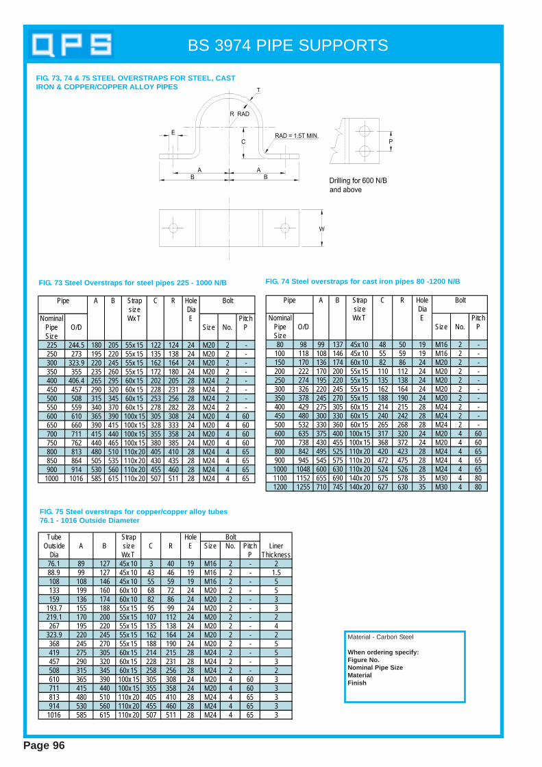
BS 3974 PIPE SUPPORTS
Page 96
A B Strap C R Holesize Dia
Nominal Wx T E PitchPipe O/D Size No. PSize225 244.5 180 205 55x 15 122 124 24 M20 2 -250 273 195 220 55x 15 135 138 24 M20 2 -300 323.9 220 245 55x 15 162 164 24 M20 2 -350 355 235 260 55x 15 172 180 24 M20 2 -400 406.4 265 295 60x 15 202 205 28 M24 2 -450 457 290 320 60x 15 228 231 28 M24 2 -500 508 315 345 60x 15 253 256 28 M24 2 -550 559 340 370 60x 15 278 282 28 M24 2 -600 610 365 390 100x 15 305 308 24 M20 4 60650 660 390 415 100x 15 328 333 24 M20 4 60700 711 415 440 100x 15 355 358 24 M20 4 60750 762 440 465 100x 15 380 385 24 M20 4 60800 813 480 510 110x 20 405 410 28 M24 4 65850 864 505 535 110x 20 430 435 28 M24 4 65900 914 530 560 110x 20 455 460 28 M24 4 65
1000 1016 585 615 110x 20 507 511 28 M24 4 65
Pipe Bolt A B Strap C R Holesize Dia
Nominal Wx T E PitchPipe O/D Size No. PSize80 98 99 137 45x 10 48 50 19 M16 2 -
100 118 108 146 45x 10 55 59 19 M16 2 -150 170 136 174 60x 10 82 86 24 M20 2 -200 222 170 200 55x 15 110 112 24 M20 2 -250 274 195 220 55x 15 135 138 24 M20 2 -300 326 220 245 55x 15 162 164 24 M20 2 -350 378 245 270 55x 15 188 190 24 M20 2 -400 429 275 305 60x 15 214 215 28 M24 2 -450 480 300 330 60x 15 240 242 28 M24 2 -500 532 330 360 60x 15 265 268 28 M24 2 -600 635 375 400 100x 15 317 320 24 M20 4 60700 738 430 455 100x 15 368 372 24 M20 4 60800 842 495 525 110x 20 420 423 28 M24 4 65900 945 545 575 110x 20 472 475 28 M24 4 651000 1048 600 630 110x 20 524 526 28 M24 4 651100 1152 655 690 140x 20 575 578 35 M30 4 801200 1255 710 745 140x 20 627 630 35 M30 4 80
Pipe Bolt
Tube Strap HoleOutside A B size C R E Size No. Pitch Liner
Dia Wx T P Thickness76.1 89 127 45x 10 3 40 19 M16 2 - 288.9 99 127 45x 10 43 46 19 M16 2 - 1.5108 108 146 45x 10 55 59 19 M16 2 - 5133 199 160 60x 10 68 72 24 M20 2 - 5159 136 174 60x 10 82 86 24 M20 2 - 3
193.7 155 188 55x 15 95 99 24 M20 2 - 3219.1 170 200 55x 15 107 112 24 M20 2 - 2267 195 220 55x 15 135 138 24 M20 2 - 4
323.9 220 245 55x 15 162 164 24 M20 2 - 2368 245 270 55x 15 188 190 24 M20 2 - 5419 275 305 60x 15 214 215 28 M24 2 - 5457 290 320 60x 15 228 231 28 M24 2 - 3508 315 345 60x 15 258 256 28 M24 2 - 2610 365 390 100x 15 305 308 24 M20 4 60 3711 415 440 100x 15 355 358 24 M20 4 60 3813 480 510 110x 20 405 410 28 M24 4 65 3914 530 560 110x 20 455 460 28 M24 4 65 3
1016 585 615 110x 20 507 511 28 M24 4 65 3
Bolt
FIG. 73 Steel Overstrap s for steel pipes 225 - 1000 N/B FIG. 74 Steel overstrap s for cast iron pipes 80 -1200 N/B
FIG. 75 Steel overstrap s for copper/copper alloy tubes76.1 - 1016 Outside Diameter
Material - Carbon Steel
When ordering specify:Figure No.Nominal Pipe SizeMaterialFinish
FIG. 73, 74 & 75 STEEL OVERSTRAPS FOR STEEL, CASTIRON & COPPER/COPPER ALLOY PIPES
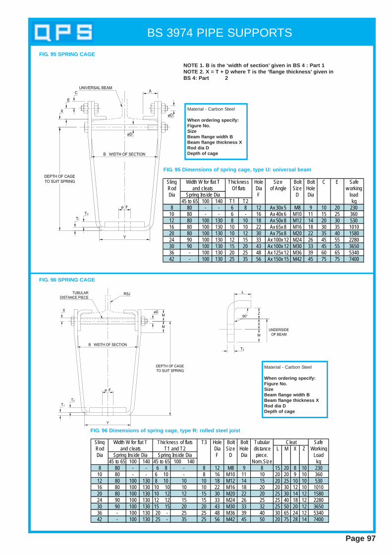
BS 3974 PIPE SUPPORTS
Page 97
FIG. 95 SPRING CAGE
Sling Hole Size Bolt Bolt C E SafeRod Dia of Angle Size Hole w orkingDia F D Dia load
45 to 65 100 140 T1 T2 kg8 80 - - 6 8 12 Ax 30x 5 M8 9 10 20 230
10 80 - - 6 - 16 Ax 40x 6 M10 11 15 25 36012 80 100 130 8 10 18 Ax 50x 8 M12 14 20 30 53016 80 100 130 10 10 22 Ax 65x 8 M16 18 30 35 101020 80 100 130 10 12 30 Ax 75x 8 M20 22 35 40 158024 90 100 130 12 15 33 Ax 100x 12 M24 26 45 55 228030 90 100 130 15 20 43 Ax 100x 12 M30 33 45 55 365036 - 100 130 20 25 48 Ax 125x 12 M36 39 60 65 534042 - 100 130 25 35 56 Ax 150x 15 M42 45 75 75 7400
Width W for flat Tand cleats
Spring Inside Dia
ThicknessOf flats
NOTE 1. B is the ‘wid th of section’ given in BS 4 : Part 1NOTE 2. X = T + D where T is the ‘flange thickness’ given inBS 4: Part 2
Material - Carbon Steel
When ordering specify:Figure No.SizeBeam flange wid th BBeam flange thickness XRod dia DDepth of cage
FIG. 95 Dimensions of spring cage, type U: universal beam
FIG. 96 SPRING CAGE
Sling T3 Hole Bolt Bolt Tubular SafeRod Dia Size Hole distance L M X Z WorkingDia F D Dia piece. Load
45 to 65 100 140 45 to 65 100 140 Nom.Size kg8 80 - - 6 8 8 12 M8 9 8 15 20 8 10 230
10 80 - - 6 10 8 16 M10 11 10 20 20 9 10 36012 80 100 130 8 10 10 18 M12 14 15 20 25 10 10 53016 80 100 130 10 10 10 22 M16 18 20 20 30 12 10 101020 80 100 130 10 12 15 30 M20 22 20 25 30 14 12 158024 90 100 130 12 12 15 33 M24 26 25 25 40 18 12 228030 90 100 130 15 15 20 43 M30 33 32 25 50 20 12 365036 - 100 130 20 - 25 48 M36 39 40 30 65 24 12 534042 - 100 130 25 - 25 56 M42 45 50 20 75 28 14 7400
15202535
-101012
Spring Inside Dia Spring Inside Dia
Cleat
-
Width W for flat T Thickness of flatsand cleats T1 and T2
FIG. 96 Dimensions of spring cage, type R: rolled steel joist
Material - Carbon Steel
When ordering specify:Figure No.SizeBeam flange wid th BBeam flange thickness XRod dia DDepth of cage
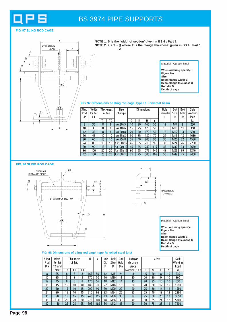
BS 3974 PIPE SUPPORTS
Page 98
FIG. 97 SLING ROD CAGE
Sling Width Size Hole Bolt Bolt SafeRod for flat of angle Diameter Size hole w orkingDia T1 F D Dia load
T1 T2 C E H Y kg8 35 8 8 Ax 30x 5 10 20 165 50 12 M8 9 230
10 35 8 8 Ax 40x 6 15 25 170 50 16 M10 11 36012 45 8 8 Ax 50x 8 20 30 170 55 18 M12 14 53016 45 10 10 Ax 65x 8 30 35 180 70 22 M16 18 101020 60 15 10 Ax 75x 8 35 40 200 90 30 M20 22 158024 80 15 10 Ax 100x 12 45 55 210 95 33 M24 26 228030 90 15 15 Ax 100x 12 45 55 240 115 43 M30 33 365036 100 20 20 Ax 125x 12 60 65 275 140 48 M36 39 534042 130 25 25 Ax 150x 15 75 75 305 165 56 M42 45 7400
Thicknessof flats
Dimensions
NOTE 1. B is the ‘wid th of section’ given in BS 4 : Part 1NOTE 2. X = T + D where T is the ‘flange thickness’ given in BS 4 : Part 1
2
Material - Carbon Steel
When ordering specify:Figure No.SizeBeam flange wid th BBeam flange thickness XRod dia DDepth of cage
FIG. 97 Dimensions of sling rod cage, type U: universal beam
FIG. 98 SLING ROD CAGE
Sling Width H Y Hole Bolt Bolt Tubular SafeRod for flat Dia Size Hole distance WorkingDia T1 and F D Dia piece Load
cleat T1 T2 T3 Nominal Size L M X Z kg8 35 8 8 8 165 50 12 M8 9 8 15 20 8 10 230
10 35 8 8 8 170 50 16 M10 11 10 20 20 9 10 36012 45 8 8 8 170 55 18 M12 14 15 20 25 10 10 53016 45 10 10 10 180 70 22 M16 18 20 20 30 12 10 101020 60 15 10 15 200 90 30 M20 22 20 25 30 14 12 158024 80 15 10 15 210 95 33 M24 26 25 25 40 18 12 228030 90 15 15 15 240 115 43 M30 33 32 25 50 20 12 365036 100 20 20 20 275 140 48 M36 39 40 30 65 24 12 534042 130 25 25 25 305 165 56 M42 45 50 30 75 28 14 7400
CleatThicknessof flats
FIG. 98 Dimensions of sling rod cage, type R: rolled steel joist
Material - Carbon Steel
When ordering specify:Figure No.SizeBeam flange wid th BBeam flange thickness XRod dia DDepth of cage
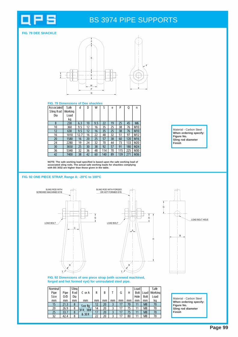
BS 3974 PIPE SUPPORTS
Page 99
Associated Safe d D W S e P Q nSling Rod Working
Dia Loadkg
8 230 6.3 10 9.5 22 19 25 45 M610 360 9.5 12 16 35 25 38 76 M1012 630 9.5 12 16 35 25 38 76 M1016 1010 12.7 16 22 48 32 51 97 M1220 1580 16 20 25 57 38 60 120 M1624 2280 19 24 32 70 44 73 133 M2030 3650 25 30 38 92 57 91 180 M2436 5340 32 36 48 114 70 115 225 M3042 7400 38 42 60 140 89 139 271 M36
NOTE: The safe working load specified is based upon the safe working load ofassociated sling rods. The actual safe working loads for shackles complyingwith BS 3032 are higher than those given in the t able.
FIG. 79 Dimensions of Dee shackles
Material - Carbon SteelWhen ordering specify:Figure No.Sling rod diameterFinish
FIG. 79 DEE SHACKLE
Nominal Sling Load Safe Pipe Pipe Rod C or A R B T G H Bolt Load WorkingSize O/D Dia Hole Bolt Loadmm mm mm mm mm mm mm mm mm mm mm kg15 21.3 8 12 20 3 17 70 11 M8 7020 26.9 8 14 20 3 17 75 11 M8 7025 33.7 8 17 20 3 17 75 11 M8 7032 42.4 8 22 20 3 17 80 11 M8 70
See fig 3FR, 3BR
& 3ER
FIG. 92 ONE PIECE STRAP, Range A: -20ºC to 100ºC
FIG. 92 Dimensions of one piece strap (with screwed machined,forged and hot formed eye) for uninsulated steel pipe.
Material - Carbon SteelWhen ordering specify:Figure No.Sling rod diameterFinish

BS 3974 PIPE SUPPORTS
c
BoltSize
M16 630 565 530 520 495 465 460 450 425 410 380 360 350 325 315 245M20 980 880 825 810 775 720 715 700 665 635 595 560 545 505 495 380M22 1210 1085 1025 1005 960 895 885 865 825 785 735 695 670 630 615 475M16 765 695 660 650 620 585 580 565 545 520 490 465 450 425 415 325M20 1190 1085 1030 1010 970 915 905 885 850 815 770 725 705 665 650 510M22 1475 1340 1275 1255 1200 1130 1120 1095 1050 1010 950 900 875 820 805 630M16 920 850 815 805 780 740 735 720 695 670 635 605 590 560 550 445M20 1435 1330 1275 1255 1215 1155 1145 1125 1085 1045 995 950 925 875 860 690M22 1775 1645 1575 1555 1505 1425 1420 1390 1340 1295 1230 1175 1145 1085 1065 855M16 1025 960 925 915 890 850 845 830 805 780 750 715 700 665 655 540M20 1600 1500 1445 1430 1390 1330 1320 1300 1260 1220 1170 1120 1095 1045 1025 845M22 1980 1855 1790 1770 1720 1645 1635 1610 1560 1510 1445 1385 1355 1290 1270 1045M16 1100 1040 1010 1000 975 935 930 920 895 870 835 805 785 755 740 620M20 1720 1625 1575 1560 1520 1460 1455 1435 1395 1355 1305 1255 1230 1180 1160 970M22 2125 2010 1950 1930 1880 1810 1800 1775 1725 1680 1615 1555 1520 1455 1435 1200M16 1155 1100 1070 1060 1040 1000 1000 985 960 940 905 875 860 825 815 690M20 1805 1720 1675 1660 1620 1565 1560 1540 1500 1465 1415 1365 1340 1290 1270 1080M22 2235 2130 2070 2050 2005 1935 1930 1905 1855 1810 1750 1690 1660 1595 1570 1335M16 1200 1150 1120 1110 1090 1055 1050 1040 1015 995 965 935 915 885 875 750M20 1875 1795 1750 1735 1705 1650 1645 1625 1590 1555 1505 1455 1435 1380 1365 1170M22 2320 2220 2165 2150 2105 2040 2035 2010 1965 1920 1860 1805 1775 1710 1685 145090 x 90 x 12
80 x 80 x 1090 x 90 x 1270 x 70 x 1080 x 80 x 10
70 x 70 x 1080 x 80 x 1090 x 90 x 1270 x 70 x 10
90 x 90 x 1270 x 70 x 1080 x 80 x 1090 x 90 x 12
80 x 80 x 1090 x 90 x 1270 x 70 x 1080 x 80 x 10
70 x 70 x 1080 x 80 x 1090 x 90 x 1270 x 70 x 10
125
150
175
35
50
75
100
Length B
52 62 68 70 75 83 84 13787 93 99 108
size
117 122 133
LengthL 188
Max imum load W (kg)
Rolledsteelangle
Beam
Depth x w idthMass B C lengthkg/m
388 40343 35289 35253 30224 25201 25238 32
610x 305 179 127 25149 20226 30
838x 292 194 133 25176 20197 30
762x 267 173 122 25147 20170 25152 25140 20125 20140 25125 20113 20101 1698 2089 2082 93 1674 1667 16122 25109 20
533x 210 101 99 2092 1682 16
457x 191
117686x 254
610x 229 108
Beam clipdimensions
914x 305
914x 419 188
137
Beam
Depth x w idthMass B C lengthkg/m74 1667 1660 1654 1267 1657 1651 1245 1054 16
305x 165 46 83 1240 1282 2074 20
457x 152 67 75 1660 1652 1243 16
254x 146 37 75 1231 1046 1239 1030 1025 839 1233 1048 16
305x 127 42 62 1637 1233 12
305x 102 28 52 1025 828 10
254x 102 25 52 1022 8
68203x 133
356x 127 62
84356x 171
406x 140 70
Beam clipdimensions
87406x 178
Dimensions of clips for universal beams.
Maximum loads ‘W’ for beam clips for universal beam application.
Note: The load given above refers to the load taken by each individual beam clip
Page 100
FIG. 101 UNIVERSAL BEAM CLAP

Dynamic Restraint s
Section 5
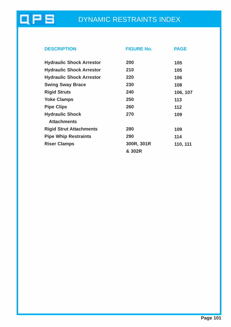
DYNAMIC RESTRAINTS INDEX
Page 101
Hydraulic Shock Arrestor
Hydraulic Shock Arrestor
Hydraulic Shock Arrestor
Swing Sway Brace
Rigid Struts
Yoke Clamps
Pipe Clips
Hydraulic Shock
Attachments
Rigid Strut Attachments
Pipe Whip Restraints
Riser Clamps
200
210
220
230
240
250
260
270
280
290
300R, 301R
& 302R
105
105
106
108
106, 107
113
112
109
109
114
110, 111
DESCRIPTION FIGURE No. PAGE
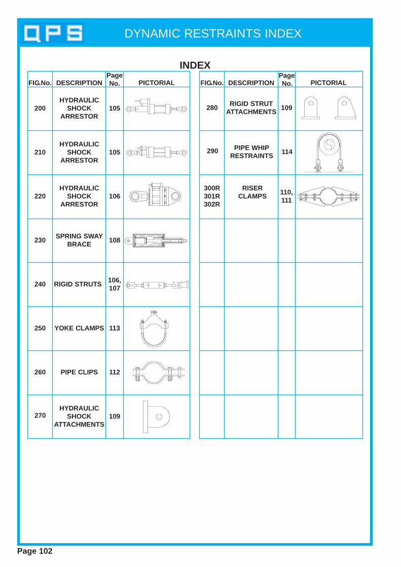
DYNAMIC RESTRAINTS INDEX
Page 102
INDEX
FIG.No. DESCRIPTIONPageNo. PICTORIAL FIG.No. DESCRIPTION
PageNo. PICTORIAL
200
210
220
230
240
250
260
300R301R302R
270
280HYDRAULIC
SHOCKARRESTOR
HYDRAULICSHOCK
ARRESTOR
HYDRAULICSHOCK
ARRESTOR
SPRING SWAYBRACE
RIGID STRUTS
YOKE CLAMPS
PIPE CLIPS
RISER CLAMPS
HYDRAULICSHOCK
ATTACHMENTS
RIGID STRUTATTACHMENTS105
105
106
108
106, 107
113
112
110, 111
109
109
290 PIPE WHIPRESTRAINTS
114
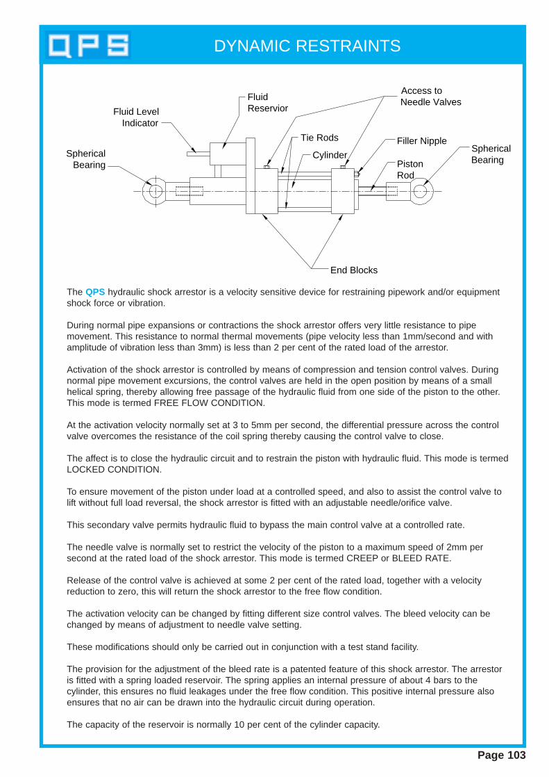
DYNAMIC RESTRAINTS
Page 103
Fluid Level Indicator
Fluid Reservior
Spherical Bearing
Tie Rods
Cylinder
Access toNeedle Valves
Filler Nipple
PistonRod
SphericalBearing
End Blocks
The QPS hydraulic shock arrestor is a velocity sensitive device for restraining pipework and/or equipmentshock force or vibration.
During normal pipe expansions or contractions the shock arrestor offers very little resistance to pipemovement. This resistance to normal thermal movements (pipe velocity less than 1mm/second and withamplitude of vibration less than 3mm) is less than 2 per cent of the rated load of the arrestor.
Activation of the shock arrestor is controlled by means of compression and tension control valves. Duringnormal pipe movement excursions, the control valves are held in the open position by means of a smallhelical spring, thereby allowing free passage of the hydraulic fluid from one side of the piston to the other.This mode is termed FREE FLOW CONDITION.
At the activation velocity normally set at 3 to 5mm per second, the differential pressure across the controlvalve overcomes the resistance of the coil spring thereby causing the control valve to close.
The affect is to close the hydraulic circuit and to restrain the piston with hydraulic fluid. This mode is termedLOCKED CONDITION.
To ensure movement of the piston under load at a controlled speed, and also to assist the control valve tolift without full load reversal, the shock arrestor is fitted with an adjustable needle/orifice valve.
This secondary valve permits hydraulic fluid to bypass the main control valve at a controlled rate.
The needle valve is normally set to restrict the velocity of the piston to a maximum speed of 2mm persecond at the rated load of the shock arrestor. This mode is termed CREEP or BLEED RATE.
Release of the control valve is achieved at some 2 per cent of the rated load, together with a velocityreduction to zero, this will return the shock arrestor to the free flow condition.
The activation velocity can be changed by fitting different size control valves. The bleed velocity can bechanged by means of adjustment to needle valve setting.
These modifications should only be carried out in conjunction with a test stand facility.
The provision for the adjustment of the bleed rate is a patented feature of this shock arrestor. The arrestoris fitted with a spring loaded reservoir. The spring applies an internal pressure of about 4 bars to thecylinder, this ensures no fluid leakages under the free flow condition. This positive internal pressure alsoensures that no air can be drawn into the hydraulic circuit during operation.
The capacity of the reservoir is normally 10 per cent of the cylinder capacity.
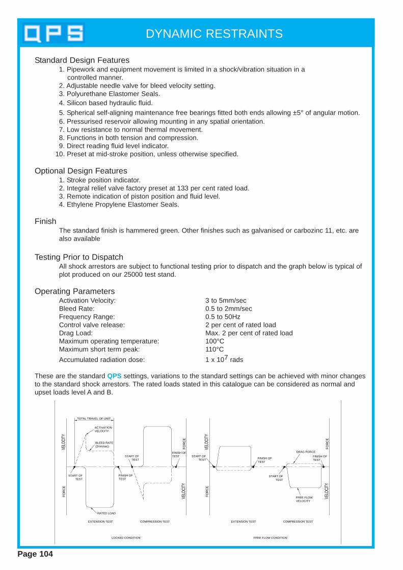
DYNAMIC RESTRAINTS
Page 104
FOR
CE
VELO
CITY
VELO
CITY
FOR
CE
TOTAL TRAVEL OF UNIT
ACTIVATION VELOCITY
BLEED RATE(2mm/sec)
START OFTEST
RATED LOAD
FINISH OF TEST
START OFTEST
FINISH OF TEST
EXTENSION TEST COMPRESSION TEST
VELO
CITY
FOR
CE
VELO
CITY
FOR
CE
START OF TEST FINISH OF
TEST
FINISH OF TEST
START OF TEST
DRAG FORCE
FREE FLOWVELOCITY
EXTENSION TEST COMPRESSION TEST
LOCKED CONDITION FREE FLOW CONDITION
Standard Design Features1. Pipework and equipment movement is limited in a shock/vibration situation in a
controlled manner.2. Adjustable needle valve for bleed velocity setting.3. Polyurethane Elastomer Seals. 4. Silicon based hydraulic fluid.5. Spherical self-aligning maintenance free bearings fitted both ends allowing ±5° of angular motion. 6. Pressurised reservoir allowing mounting in any spatial orientation.7. Low resistance to normal thermal movement.8. Functions in both tension and compression.9. Direct reading fluid level indicator.
10. Preset at mid-stroke position, unless otherwise specified.
Optional Design Features1. Stroke position indicator.2. Integral relief valve factory preset at 133 per cent rated load.3. Remote indication of piston position and fluid level.4. Ethylene Propylene Elastomer Seals.
FinishThe standard finish is hammered green. Other finishes such as galvanised or carbozinc 11, etc. are also available
Testing Prior to DispatchAll shock arrestors are subject to functional testing prior to dispatch and the graph below is typical of plot produced on our 25000 test stand.
Operating ParametersActivation Velocity: 3 to 5mm/secBleed Rate: 0.5 to 2mm/secFrequency Range: 0.5 to 50HzControl valve release: 2 per cent of rated loadDrag Load: Max. 2 per cent of rated loadMaximum operating temperature: 100°CMaximum short term peak: 110°C
Accumulated radiation dose: 1 x 10⁷ rads
These are the standard QPS settings, variations to the standard settings can be achieved with minor changesto the standard shock arrestors. The rated loads stated in this catalogue can be considered as normal andupset loads level A and B.
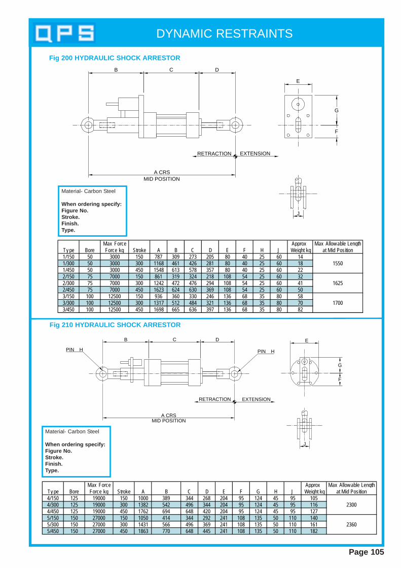
DYNAMIC RESTRAINTS
Page 105
E
G
F
RETRACTION
A CRS
J
EXTENSION
MID POSITION
B C D
Max Force Approx Max Allow able LengthTy pe Bore Force kg Stroke A B C D E F H J Weight kg at Mid Position1/150 50 3000 150 787 309 273 205 80 40 25 60 141/300 50 3000 300 1168 461 426 281 80 40 25 60 18 15501/450 50 3000 450 1548 613 578 357 80 40 25 60 222/150 75 7000 150 861 319 324 218 108 54 25 60 322/300 75 7000 300 1242 472 476 294 108 54 25 60 41 16252/450 75 7000 450 1623 624 630 369 108 54 25 60 503/150 100 12500 150 936 360 330 246 136 68 35 80 583/300 100 12500 300 1317 512 484 321 136 68 35 80 70 17003/450 100 12500 450 1698 665 636 397 136 68 35 80 82
B C D
A CRSMID POSITION
PIN H
RETRACTION EXTENSION
PIN H
E
G
F
J
Max Force Approx Max Allow able LengthTy pe Bore Force kg Stroke A B C D E F G H J Weight kg at Mid Position4/150 125 19000 150 1000 389 344 268 204 95 124 45 95 1054/300 125 19000 300 1382 542 496 344 204 95 124 45 95 116 23004/450 125 19000 450 1762 694 648 420 204 95 124 45 95 1275/150 150 27000 150 1050 414 344 292 241 108 135 50 110 1405/300 150 27000 300 1431 566 496 369 241 108 135 50 110 161 23605/450 150 27000 450 1863 770 648 445 241 108 135 50 110 182
Fig 200 HYDRAULIC SHOCK ARRESTOR
Fig 210 HYDRAULIC SHOCK ARRESTOR
Material- Carbon Steel
When ordering specify:Figure No.Stroke.Finish.Type.
Material- Carbon Steel
When ordering specify:Figure No.Stroke.Finish.Type.
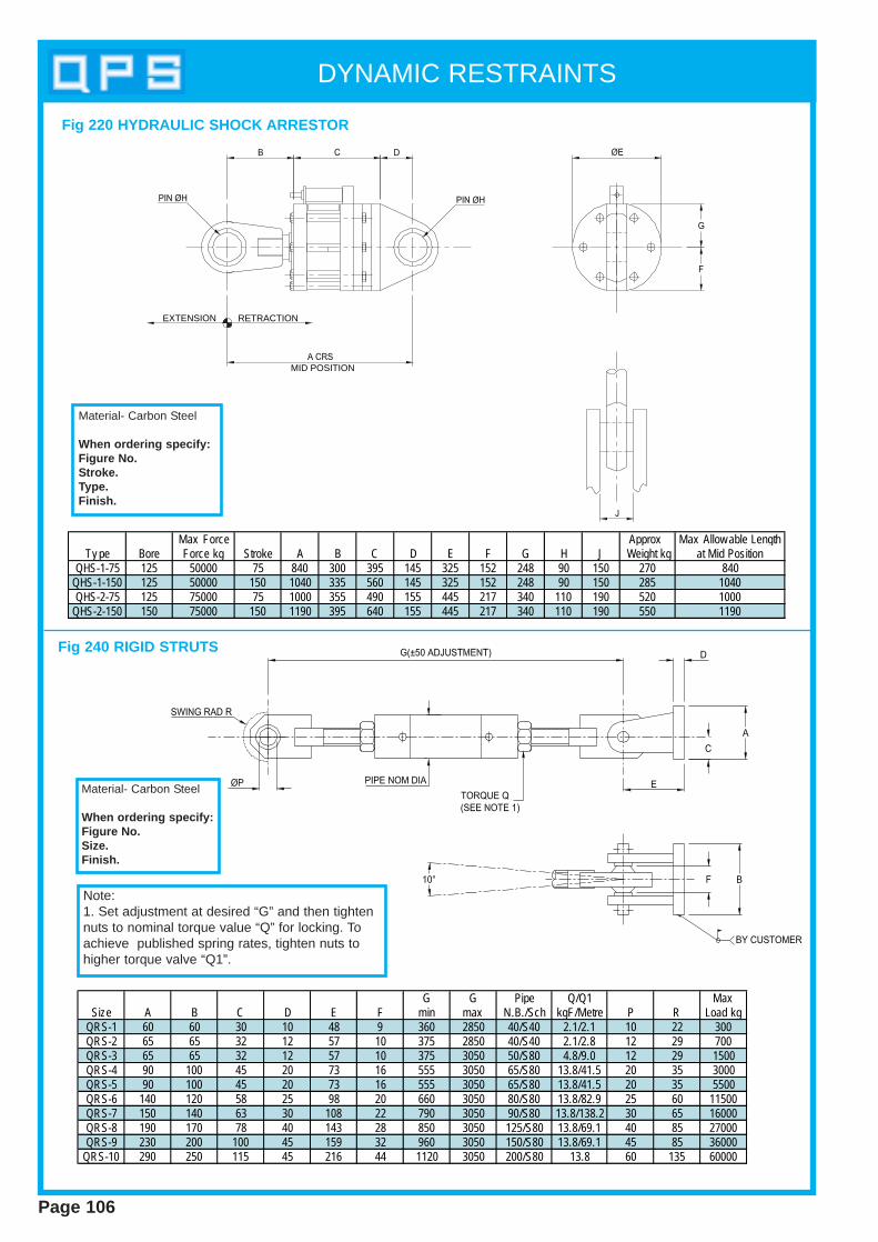
DYNAMIC RESTRAINTS
Page 106
EXTENSION RETRACTION
MID POSITION
Max Force Approx Max Allow able LengthTy pe Bore Force kg Stroke A B C D E F G H J Weight kg at Mid Position
QHS-1-75 125 50000 75 840 300 395 145 325 152 248 90 150 270 840QHS-1-150 125 50000 150 1040 335 560 145 325 152 248 90 150 285 1040QHS-2-75 125 75000 75 1000 355 490 155 445 217 340 110 190 520 1000
QHS-2-150 150 75000 150 1190 395 640 155 445 217 340 110 190 550 1190
Fig 220 HYDRAULIC SHOCK ARRESTOR
Material- Carbon Steel
When ordering specify:Figure No.Stroke.Type.Finish.
G G Pipe Q/Q1 MaxSize A B C D E F min max N.B./Sch kgF/Metre P R Load kg
QRS-1 60 60 30 10 48 9 360 2850 40/S40 2.1/2.1 10 22 300QRS-2 65 65 32 12 57 10 375 2850 40/S40 2.1/2.8 12 29 700QRS-3 65 65 32 12 57 10 375 3050 50/S80 4.8/9.0 12 29 1500QRS-4 90 100 45 20 73 16 555 3050 65/S80 13.8/41.5 20 35 3000QRS-5 90 100 45 20 73 16 555 3050 65/S80 13.8/41.5 20 35 5500QRS-6 140 120 58 25 98 20 660 3050 80/S80 13.8/82.9 25 60 11500QRS-7 150 140 63 30 108 22 790 3050 90/S80 13.8/138.2 30 65 16000QRS-8 190 170 78 40 143 28 850 3050 125/S80 13.8/69.1 40 85 27000QRS-9 230 200 100 45 159 32 960 3050 150/S80 13.8/69.1 45 85 36000
QRS-10 290 250 115 45 216 44 1120 3050 200/S80 13.8 60 135 60000
Note:1. Set adjustment at desired “G” and then tightennuts to nominal torque value “Q” for locking. Toachieve published spring rates, tighten nuts tohigher torque valve “Q1”.
Material- Carbon Steel
When ordering specify:Figure No.Size.Finish.
Fig 240 RIGID STRUTS

DYNAMIC RESTRAINTS
Page 107
This range of high stiffness rigid struts has been specifically developedby QPS for use in the nuclear power industry.It is available in 10 sizes ranging from 300 kg to 60000 kg.Stiffness values have been determined by test.
2000 400 600 800 1000 1200 1400 1600 1800 2000 2200 2400 2600 2800 3000 3200 36003400
5
10
15
25
30
35
40
45
50
55
60
65
70
20
QRS-1QRS-2
QRS-3
QRS-4/5
QRS-7
QRS-8
QRS-9
QRS-6
PIN to PIN ("G") in mm
SP
RIN
G R
AT
E (
10‡
kg/m
m)
2850
max
Fig 240 RIGID STRUTS

DYNAMIC RESTRAINTS
Page 108
Max Rod Rod Spring Max Length at Pin Plate Take Use w ith
Pipe Preload Rate Force Max Force Dia Thick Out StructuralSize Size kg kg mm kg M/mm L K J A B C D E F G H Attachments
1 50-90 23 0.89 90 1500 20 12 12 115 345 42 400 100 25 225 30 2 100-200 68 2.68 270 1000 24 12 12 115 360 42 415 120 25 225 30 fig 280-153 225-600 204 8.04 815 1000 24 12 12 115 450 42 505 150 25 280 304 225-600 400 16.07 1630 1000 30 20 12 168 430 58 515 140 40 270 455 225-600 614 24.48 2540 1000 36 20 20 168 470 58 575 150 50 312 50 fig 280-556 225-600 820 32.66 3270 1000 36 20 20 168 520 58 625 150 50 362 50
The QPS spring sway brace has been designed in six sizes related to specific pipe sizes. For normalapplication it is permissible to select on the basis of pipe sizes and loads. When dealing with complexsituations the unit should be selected on a calculated basis.
The amount of energy required to control the pipework should be proportional to the mass of the pipework.Factors such as the amplitude, frequency or vibration, the nature of the vibration and the angle of the swaybrace from the axis of the movement should all be considered.
The unit comprises a pre-load spring which can be extended or compressed in order to give increasingresistance in both directions. This increase in resistance overcomes the dynamic forces generated by theequipment thereby damping vibrations, opposing sway and absorbing shock forces.All units have 75mm travel in both tension and compressions direction.
Size range: 1 to 6Preset loads: 23 kg to 820 kgMaximum force: 90 kg to 3270 kg
Standard Design Features1. Compact design suitable for use in a confined space.2. All units have 75mm travel in either direction.3. Vibration is opposed with an instantaneous counterforce returning the pipe to its normal position.4. Rod coupling allows limited rate adjustment.5. Standard finish- hammer paint.6. SB 45 Sway brace and vibration control unit is shipped ready for installation.
Optional Features 1. Can be supplied galvanised with a plastic coated spring.2. Larger sizes can be custom-designed to suit clients requirements.
Fig 230 SPRING SWAY BRACE
Material- Carbon Steel
When ordering specify:Figure No.Size.Finish.
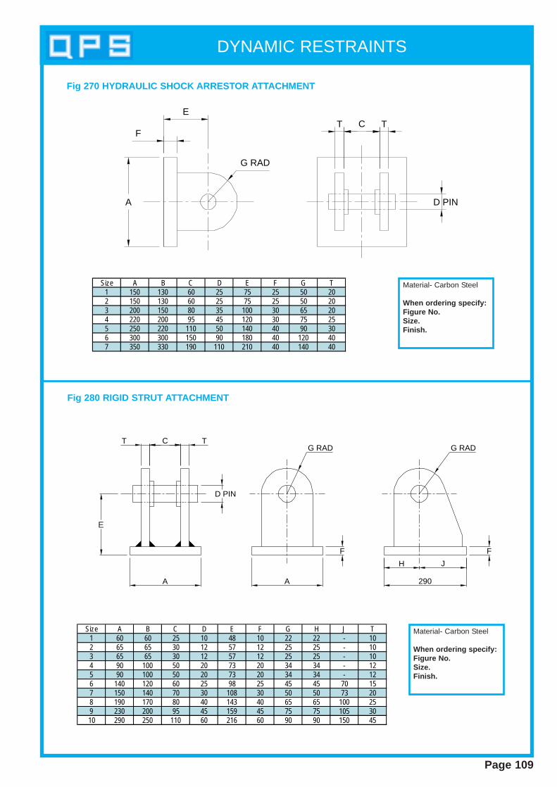
DYNAMIC RESTRAINTS
Page 109
T C TE
F
A
G RAD
D PIN
Fig 270 HYDRAULIC SHOCK ARRESTOR ATTACHMENT
Fig 280 RIGID STRUT ATTACHMENT
CT T
D PIN
G RAD G RAD
AA 290
H J
F F
E
Size A B C D E F G H J T1 60 60 25 10 48 10 22 22 - 102 65 65 30 12 57 12 25 25 - 103 65 65 30 12 57 12 25 25 - 104 90 100 50 20 73 20 34 34 - 125 90 100 50 20 73 20 34 34 - 126 140 120 60 25 98 25 45 45 70 157 150 140 70 30 108 30 50 50 73 208 190 170 80 40 143 40 65 65 100 259 230 200 95 45 159 45 75 75 105 3010 290 250 110 60 216 60 90 90 150 45
Size A B C D E F G T1 150 130 60 25 75 25 50 202 150 130 60 25 75 25 50 203 200 150 80 35 100 30 65 204 220 200 95 45 120 30 75 255 250 220 110 50 140 40 90 306 300 300 150 90 180 40 120 407 350 330 190 110 210 40 140 40
Material- Carbon Steel
When ordering specify:Figure No.Size.Finish.
Material- Carbon Steel
When ordering specify:Figure No.Size.Finish.
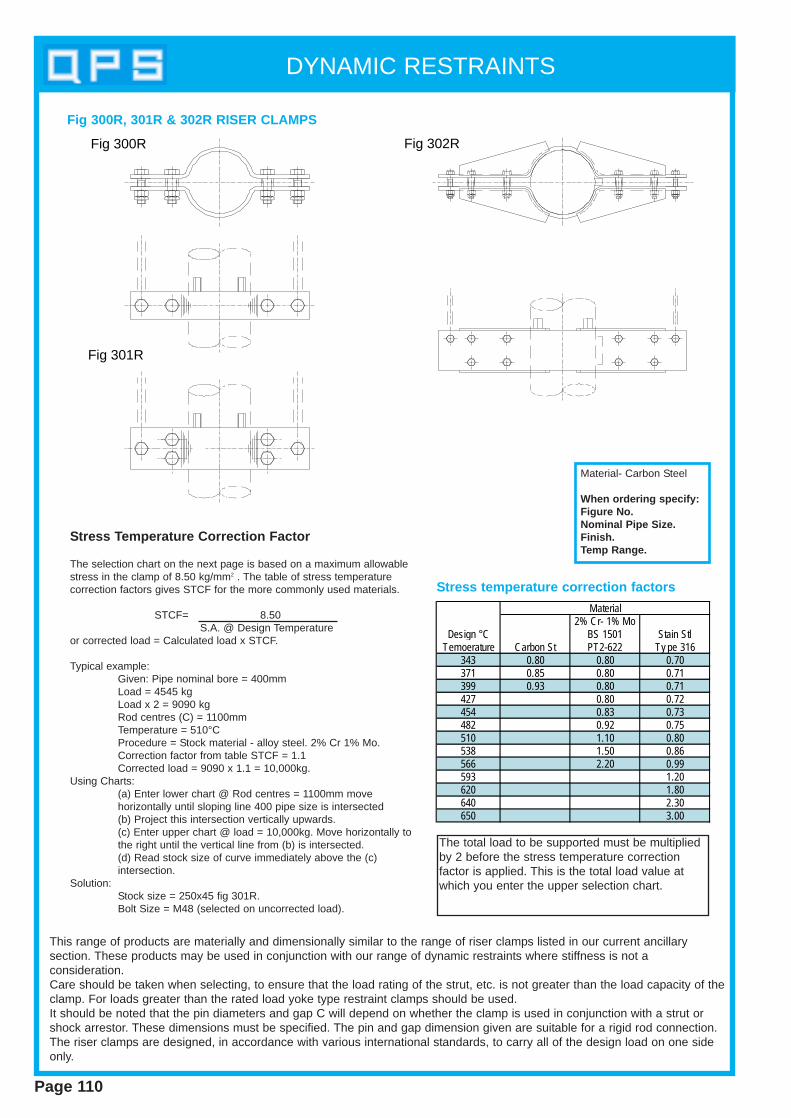
DYNAMIC RESTRAINTS
Page 110
Fig 300R
Fig 301R
Fig 302R
Stress T emperature Correction Factor
The selection chart on the next page is based on a maximum allowablestress in the clamp of 8.50 kg/mm2 . The table of stress temperaturecorrection factors gives STCF for the more commonly used materials.
STCF= 8.50S.A. @ Design Temperature
or corrected load = Calculated load x STCF.
Typical example:Given: Pipe nominal bore = 400mmLoad = 4545 kgLoad x 2 = 9090 kgRod centres (C) = 1100mmTemperature = 510°CProcedure = Stock material - alloy steel. 2% Cr 1% Mo.Correction factor from table STCF = 1.1Corrected load = 9090 x 1.1 = 10,000kg.
Using Charts:(a) Enter lower chart @ Rod centres = 1100mm move horizontally until sloping line 400 pipe size is intersected(b) Project this intersection vertically upwards.(c) Enter upper chart @ load = 10,000kg. Move horizontally to the right until the vertical line from (b) is intersected.(d) Read stock size of curve immediately above the (c) intersection.
Solution:Stock size = 250x45 fig 301R.Bolt Size = M48 (selected on uncorrected load).
2% Cr- 1% MoDesign °C BS 1501 Stain Stl
Temoerature Carbon St PT2-622 Ty pe 316343 0.80 0.80 0.70371 0.85 0.80 0.71399 0.93 0.80 0.71427 0.80 0.72454 0.83 0.73482 0.92 0.75510 1.10 0.80538 1.50 0.86566 2.20 0.99593 1.20620 1.80640 2.30650 3.00
Material
Fig 300R, 301R & 302R RISER CLAMPS
Stress temperature correction factors
Material- Carbon Steel
When ordering specify:Figure No.Nominal Pipe Size.Finish.Temp Range.
This range of products are materially and dimensionally similar to the range of riser clamps listed in our current ancillarysection. These products may be used in conjunction with our range of dynamic restraints where stiffness is not aconsideration.Care should be taken when selecting, to ensure that the load rating of the strut, etc. is not greater than the load capacity of theclamp. For loads greater than the rated load yoke type restraint clamps should be used.It should be noted that the pin diameters and gap C will depend on whether the clamp is used in conjunction with a strut orshock arrestor. These dimensions must be specified. The pin and gap dimension given are suitable for a rigid rod connection.The riser clamps are designed, in accordance with various international standards, to carry all of the design load on one sideonly.
The total load to be supported must be multipliedby 2 before the stress temperature correctionfactor is applied. This is the total load value atwhich you enter the upper selection chart.
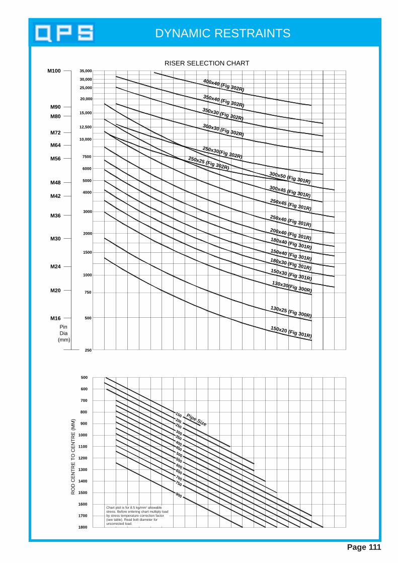
DYNAMIC RESTRAINTS
Page 111
M16
M20
M24
M30
M36
M42
M48
M56
M64
M72
M80
M90
900
750
700
650
600
550
500
450
400
350
300
250
200
150
1800
1700
1600
1500
1400
1300
1200
1100
1000
900
800
700
600
500
250
500
750
1000
1500
2000
3000
4000
5000
6000
7500
10,000
12,500
15,000
20,000
25,000
30,000
35,000
RISER SELECTION CHARTR
OD
CE
NT
RE
TO
CE
NT
RE
(M
M)
Pin Dia(mm)
M100
400x40 (Fig 302R)350x40 (Fig 302R)350x30 (Fig 302R)300x30 (Fig 302R)
250x30(Fig 302R)250x25 (Fig 302R)300x50 (Fig 301R)300x45 (Fig 301R)250x45 (Fig 301R)
250x40 (Fig 301R)200x40 (Fig 301R)180x40 (Fig 301R)150x40 (Fig 301R)180x30 (Fig 301R)150x30 (Fig 301R)130x30(Fig 300R)
130x25 (Fig 300R)
150x20 (Fig 301R)
Pipe Size
Chart plot is for 8.5 kg/mm2 allowablestress. Before entering chart multiply loadby stress temperature correction factor(see table). Read bolt diameter foruncorrected load.
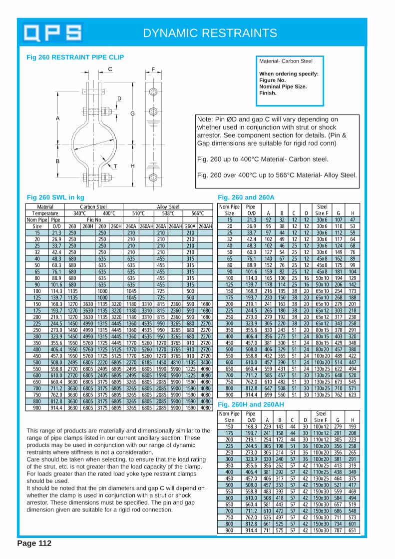
DYNAMIC RESTRAINTS
Page 112
This range of products are materially and dimensionally similar to therange of pipe clamps listed in our current ancillary section. Theseproducts may be used in conjunction with our range of dynamicrestraints where stiffness is not a consideration.Care should be taken when selecting, to ensure that the load ratingof the strut, etc. is not greater than the load capacity of the clamp.For loads greater than the rated load yoke type restraint clampsshould be used.It should be noted that the pin diameters and gap C will depend onwhether the clamp is used in conjunction with a strut or shockarrestor. These dimensions must be specified. The pin and gapdimension given are suitable for a rigid rod connection.
B
A
T H
G
C
D
F
Note: Pin ØD and gap C will vary depending onwhether used in conjunction with strut or shockarrestor. See component section for details. (Pin &Gap dimensions are suitable for rigid rod conn)
Fig. 260 up to 400°C Material- Carbon steel.
Fig. 260 over 400°C up to 566°C Material- Alloy Steel.
Fig. 260 and 260AFig 260 SWL in kg
Fig. 260H and 260AHNom Pipe Pipe Steel
Size O/D A B C D Size F G H150 168.3 229 143 44 30 100x 12 279 193175 193.7 241 158 44 30 110x 12 291 208200 219.1 254 172 44 30 110x 12 305 223225 244.5 305 198 51 36 100x 20 356 258250 273.0 305 214 51 36 100x 20 356 265300 323.9 330 240 57 36 100x 20 381 291350 355.6 356 262 57 42 110x 25 413 319400 406.4 381 292 57 42 110x 25 438 349450 457.0 406 317 57 42 130x 25 464 375500 508.0 457 353 57 42 150x 30 521 417550 558.8 483 393 57 42 150x 30 559 469600 610.0 508 418 57 42 150x 30 584 494650 660.4 581 443 57 42 150x 30 657 519700 711.2 610 472 57 42 150x 30 686 548750 762.0 635 497 57 42 150x 30 711 573800 812.8 661 525 57 42 150x 30 734 601900 914.4 711 575 57 42 150x 30 787 651
Nom Pipe Pipe SteelSize O/D A B C D Size F G H15 21.3 92 32 12 12 30x 6 107 4720 26.9 95 38 12 12 30x 6 110 5325 33.7 97 44 12 12 30x 6 112 5932 42.4 102 49 12 12 30x 6 117 6440 48.3 102 46 25 12 30x 6 124 6850 60.3 127 54 25 12 30x 6 149 7665 76.1 140 67 25 12 45x 8 162 8980 88.9 152 76 25 12 45x 8 175 9990 101.6 159 82 25 12 45x 8 181 104
100 114.3 165 100 25 16 50x 10 194 129125 139.7 178 114 25 16 50x 10 206 142150 168.3 216 135 38 20 65x 10 254 173175 193.7 230 150 38 20 65x 10 268 188200 219.1 241 163 38 20 65x 10 279 201225 244.5 265 180 38 20 65x 12 303 218250 273.0 279 192 38 20 65x 12 317 230300 323.9 305 220 38 20 65x 12 343 258350 355.6 330 243 51 20 80x 15 378 291400 406.4 356 273 51 24 80x 15 403 320450 457.0 381 300 51 24 80x 15 429 348500 508.0 406 329 51 24 80x 20 457 380550 558.8 432 365 51 24 100x 20 489 422600 610.0 457 390 51 24 100x 20 514 447650 660.4 559 431 51 24 130x 25 622 494700 711.2 585 457 51 30 130x 25 648 520750 762.0 610 482 51 30 130x 25 673 545800 812.8 647 508 51 30 130x 25 710 571900 914.4 699 560 51 30 130x 25 762 623
Fig 260 RESTRAINT PIPE CLIP
Nom Pipe Pipe Size O/D 260 260H 260 260H 260A 260AH 260A 260AH 260A 260AH15 21.3 250 250 210 210 21020 26.9 250 250 210 210 21025 33.7 250 250 210 210 21032 42.4 250 250 210 210 21040 48.3 680 635 635 455 31550 60.3 680 635 635 455 31565 76.1 680 635 635 455 31580 88.9 680 635 635 455 31590 101.6 680 635 635 455 315
100 114.3 1135 1000 1045 725 500125 139.7 1135 1000 1045 725 500150 168.3 1270 3630 1135 3220 1180 3310 815 2360 590 1680175 193.7 1270 3630 1135 3220 1180 3310 815 2360 590 1680200 219.1 1270 3630 1135 3220 1180 3310 815 2360 590 1680225 244.5 1450 4990 1315 4445 1360 4535 950 3265 680 2270250 273.0 1450 4990 1315 4445 1360 4535 950 3265 680 2270300 323.9 1450 4990 1315 4445 1360 4535 950 3265 680 2270350 355.6 1950 5760 1725 4445 1770 5260 1270 3765 910 2720400 406.4 1950 5760 1725 5125 1770 5260 1270 3765 910 2720450 457.0 1950 5760 1725 5125 1770 5260 1270 3765 910 2720500 508.0 2495 6805 2220 6805 2270 6185 1450 4810 1135 3400550 558.8 2720 6805 2405 6805 2495 6805 1590 5900 1225 4080600 610.0 2720 6805 2405 6805 2495 6805 1590 5900 1225 4080650 660.4 3630 6805 3175 6805 3265 6805 2085 5900 1590 4080700 711.2 3630 6805 3175 6805 3265 6805 2085 5900 1590 4080750 762.0 3630 6805 3175 6805 3265 6805 2085 5900 1590 4080800 812.8 3630 6805 3175 6805 3265 6805 2085 5900 1590 4080900 914.4 3630 6805 3175 6805 3265 6805 2085 5900 1590 4080
Fig No340°C 400°C 510°CTemperature
Material538°C 566°C
Alloy SteelCarbon Steel
Material- Carbon Steel
When ordering specify:Figure No.Nominal Pipe Size.Finish.
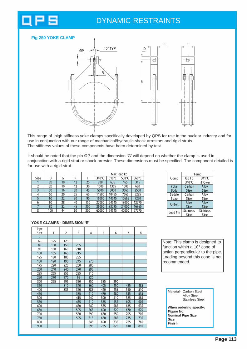
DYNAMIC RESTRAINTS
Page 113
This range of high stiffness yoke clamps specifically developed by QPS for use in the nuclear industry and foruse in conjunction with our range of mechanical/hydraulic shock arrestors and rigid struts.The stiffness values of these components have been determined by test.
It should be noted that the pin ØP and the dimension ‘G’ will depend on whether the clamp is used inconjunction with a rigid strut or shock arrestor. These dimensions must be specified. The component detailed isfor use with a rigid strut.
Size D G P T 340°C 510°C 538°C 566°C1 20 10 12 25 700 635 465 3152 20 10 12 30 1500 1365 1000 6803 30 16 20 45 5500 5000 3665 25004 50 20 25 65 11500 10455 7665 52255 60 22 30 90 16000 14545 10665 72706 60 28 40 150 27000 24545 18000 122707 80 32 45 200 36000 32725 24000 163608 100 44 60 200 60000 54545 40000 27270
Max load kg
PipeSize 1 2 3 4 5 6 7 8
-65 125 12580 150 150 20590 160 160 210
100 165 165 215125 180 180 235150 190 190 245 270175 220 220 260 285200 240 240 270 295225 255 255 285 310250 270 270 95 320300 295 295 320 350 385 390350 310 340 360 405 450 485 485400 335 360 385 440 455 510 510450 385 410 470 480 535 535500 415 440 500 510 585 585550 435 510 535 555 605 605600 460 540 565 585 635 635650 505 565 600 620 670 670700 550 590 630 650 705 705750 595 615 660 685 735 735800 645 690 735 765 765900 695 735 825 810 810
Note: This clamp is designed tofunction within a 10° cone ofaction perpendicular to the pipe.Loading beyond this cone is notrecommended.
Comp Up To 341°C340°C & Ov er
Yoke Carbon AlloyBody Steel Steel
Saddle Carbon AlloyStrap Steel Steel
Alloy AlloySteel Steel
Stainless StainlessSteel Steel
Temp
U-Bolt
Load Pin
Fig 250 YOKE CLAMP
YOKE CLAMPS - DIMENSION ‘E’
Material- Carbon SteelAlloy SteelStainless Steel
When ordering specify:Figure No.Nominal Pipe Size.Size.Finish.

DYNAMIC RESTRAINTS
Page 114
The QPS pipe whip is an elastic device which restrains pipework and absorbs energy in theevent of pipe failure.
In the unlikely event of a rupture or break in a pressure pipe system, the large jet forcesgenerated by escaping fluid may cause the pipework to “whip”, that is to move in a direction which isat an angle to the the original longitudinal axis of the pipe.
It is desirable to provide pipe restraint devices which will limit the movement of the rupturedpipe, and to prevent impact damage to the local components.
This type of whip restraint offers the following features :-
1. The restraint absorbs the energy of the moving pipe and has high energy absorption in relation to its size.
2. The restraint is compact in size.
3. The restraint provides a relatively large normal clearance between the restraint and the pipe to allow for normal thermal movement.
4. Design of restraints undertaken to suit specific customer requirements.
Fig 290 PIPE WHIP RESTRAINTS
Material- Carbon Steel
When ordering specify:Figure No.Nominal Pipe Size.Finish.
Isolation Equipment
Section 6
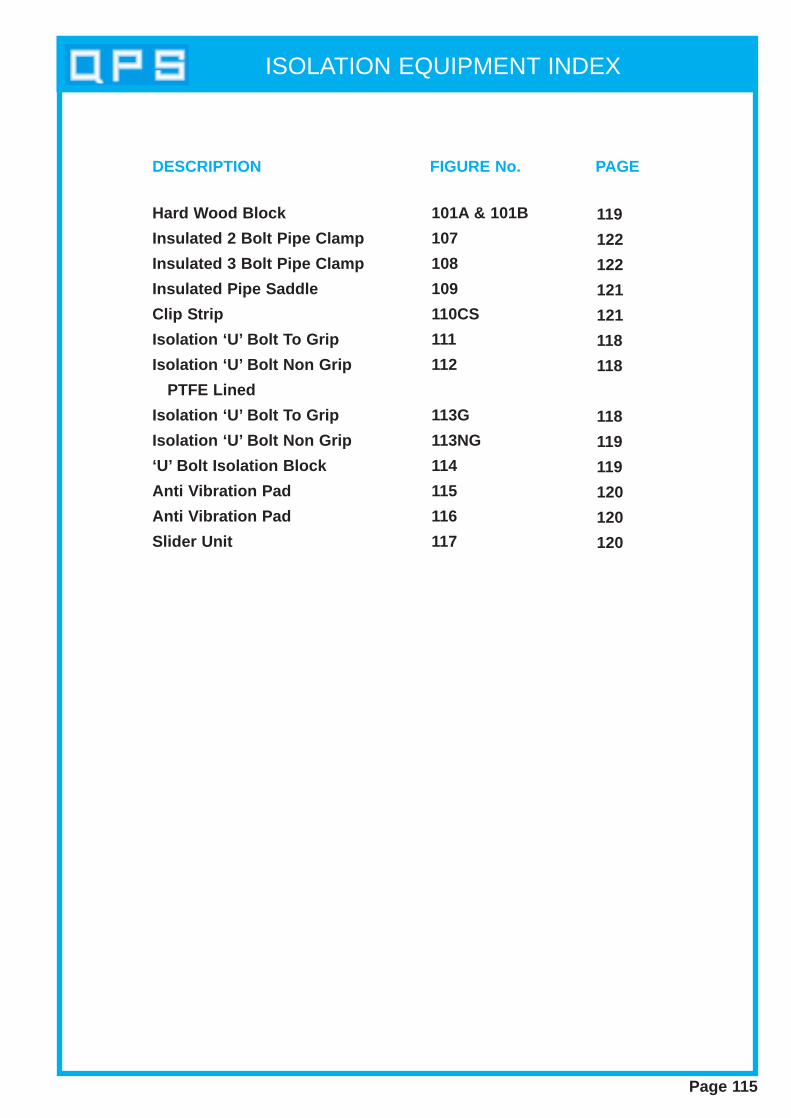
ISOLATION EQUIPMENT INDEX
Page 115
Hard Wood Block
Insulated 2 Bolt Pipe Clamp
Insulated 3 Bolt Pipe Clamp
Insulated Pipe Saddle
Clip Strip
Isolation ‘U’ Bolt To Grip
Isolation ‘U’ Bolt Non Grip
PTFE Lined
Isolation ‘U’ Bolt To Grip
Isolation ‘U’ Bolt Non Grip
‘U’ Bolt Isolation Block
Anti Vibration Pad
Anti Vibration Pad
Slider Unit
101A & 101B
107
108
109
110CS
111
112
113G
113NG
114
115
116
117
119
122
122
121
121
118
118
118
119
119
120
120
120
DESCRIPTION FIGURE No. PAGE
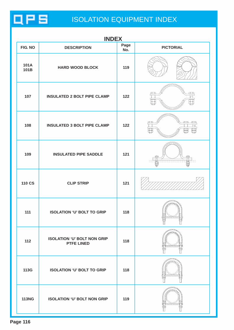
ISOLATION EQUIPMENT INDEX
INDEXFIG. NO DESCRIPTION
PageNo.
PICTORIAL
101A101B
107
HARD WOOD BLOCK 119
INSULATED 2 BOLT PIPE CLAMP 122
108
109
110 CS
111
112
113G
113NG
INSULATED 3 BOLT PIPE CLAMP
INSULATED PIPE SADDLE
CLIP STRIP
ISOLATION ‘U’ BOLT TO GRIP
ISOLATION ‘U’ BOLT NON GRIPPTFE LINED
ISOLATION ‘U’ BOLT TO GRIP
ISOLATION ‘U’ BOLT NON GRIP
122
121
121
118
118
118
119
Page 116
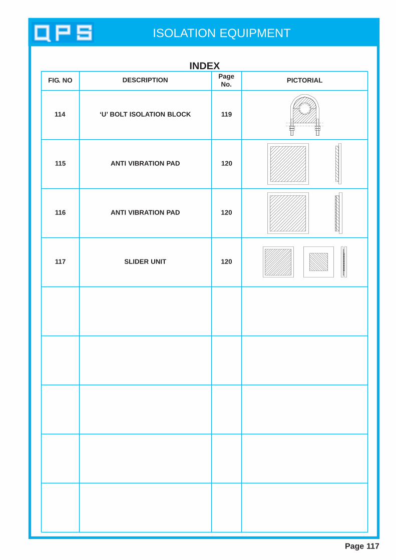
ISOLATION EQUIPMENT
Page 117
INDEXFIG. NO DESCRIPTION Page
No.PICTORIAL
114
115
116
117
‘U’ BOLT ISOLATION BLOCK
ANTI VIBRATION PAD
ANTI VIBRATION PAD
SLIDER UNIT
119
120
120
120

ISOLATION EQUIPMENT
Page 118
Pipe MaxSize A B C D E F Load kg16.0 60 60 32 6 60 10 22020.0 65 60 36 6 70 10 22025.0 65 60 41 6 75 10 22030.0 75 65 46 6 85 10 22038.0 80 70 64 10 95 10 54544.5 80 70 71 10 100 10 54557.0 90 75 83 10 110 10 54576.1 95 75 102 12 135 10 100088.9 100 75 115 12 140 10 1000108.0 110 75 134 12 170 10 1000159.0 180 120 201 16 250 15 1635219.1 200 120 262 16 315 15 1635267.0 235 120 318 20 370 15 3405324.0 265 120 375 20 425 15 3405
Pipe MaxSize A B C D E F Load kg15 62 58 38 6 60 10 22020 65 60 44 6 70 10 22025 65 60 50 6 72 10 22032 70 68 70 10 90 10 54540 82 76 76 10 112 10 54550 92 76 88 10 112 10 54580 100 76 115 12 142 10 1000100 112 80 140 12 168 10 1000125 135 89 166 12 200 10 1000150 180 120 210 16 245 15 1635200 200 120 262 16 300 15 1635225 210 120 287 16 345 15 3405250 225 121 316 16 374 15 3405300 250 120 366 16 424 15 3405350 265 120 399 16 457 15 3405400 300 130 449 16 507 15 3405
TO SUIT GALV & ST. ST. PIPE
TO SUIT CUPRO-NICKEL PIPES
FIG. 111 ISOLATION ‘U’ BOLT (TO GRIP) Material - ‘U’ Bolt Carbon SteelIsolation - Cork Rubber / Extruded F.RNeoprene Complete with 4 Nuts
When ordering specify:Fig. No.Nominal Pipe Size
Pipe MaxSize A B C D E F Load kg16.0 60 60 32 6 60 10 22020.0 65 60 36 6 70 10 22025.0 65 60 41 6 75 10 22030.0 75 65 46 6 85 10 22038.0 80 70 64 10 95 10 54544.5 80 70 71 10 100 10 54557.0 90 75 83 10 110 10 54576.1 95 75 102 12 135 10 100088.9 100 75 115 12 140 10 1000108.0 110 75 134 12 170 10 1000159.0 180 120 201 16 250 15 1635219.1 200 120 262 16 315 15 1635267.0 235 120 318 20 370 15 3405324.0 265 120 375 20 425 15 3405
Pipe Max Size A B C D E F Load kg*15 62 58 38 6 60 10 220*20 65 60 44 6 70 10 220*25 65 60 50 6 72 10 22032 70 68 70 10 90 10 54540 82 76 76 10 112 10 54550 92 76 88 10 112 10 54580 100 76 115 12 142 10 1000100 112 80 140 12 168 10 1000125 135 89 166 12 200 10 1000150 180 120 210 16 245 15 1635200 200 120 262 16 300 15 1635225 210 120 287 16 345 15 3405250 225 121 316 16 374 15 3405300 250 120 366 16 424 15 3405350 265 120 399 16 457 15 3405400 300 130 449 16 507 15 3405
PipeSize152025
*NOTESpacers&Washers Not Required
Material - ‘U’ Bolt Carbon SteelIsolation - Cork Rubber / P.T.F.E ExtrudedF.R Neoprene Complete with 4 Nuts
When ordering specify:Fig. No.Nominal Pipe Size
TO SUIT CUPRO-NICKEL PIPESFIG. 112 ISOLATION ‘U’ BOLT (NON GRIP)
Material - ‘U’ Bolt Carbon SteelIsolation - Cork Rubber / ExtrudedF.R Neoprene Complete with 4 Nuts
When ordering specify:Fig. No.Nominal Pipe Size
Pipe MaxSize A B C D E F Load kg16.0 60 60 32 6 60 10 22020.0 65 60 36 6 70 10 22025.0 65 60 41 6 75 10 22030.0 75 65 46 6 85 10 22038.0 80 70 64 10 95 10 54544.5 80 70 71 10 100 10 54557.0 90 75 83 10 110 10 54576.1 95 75 102 12 135 10 100088.9 100 75 115 12 140 10 1000108.0 110 75 134 12 170 10 1000159.0 180 120 201 16 250 15 1635219.1 200 120 262 16 315 15 1635267.0 235 120 318 20 370 15 3405324.0 265 120 375 20 425 15 3405
Pipe MaxSize A B C D E F Load kg15 62 58 38 6 60 10 22020 65 60 44 6 70 10 22025 65 60 50 6 72 10 22032 70 68 70 10 90 10 54540 82 76 76 10 112 10 54550 92 76 88 10 112 10 54580 100 76 115 12 142 10 1000100 112 80 140 12 168 10 1000125 135 89 166 12 200 10 1000150 180 120 210 16 245 15 1635200 200 120 262 16 300 15 1635225 210 120 287 16 345 15 3405250 225 121 316 16 374 15 3405300 250 120 366 16 424 15 3405350 265 120 399 16 457 15 3405400 300 130 449 16 507 15 3405
TO SUIT GALV & ST. ST. PIPE TO SUIT CUPRO-NICKEL PIPESFIG. 113G ISOLATION ‘U’ BOLT (TO GRIP)
D
E
F
BA
C
D
E
F
BA
C
SPACER
P.T.F.E LINER
D
E
F
BA
C
SPACER
TO SUIT GALV & ST. ST. PIPE
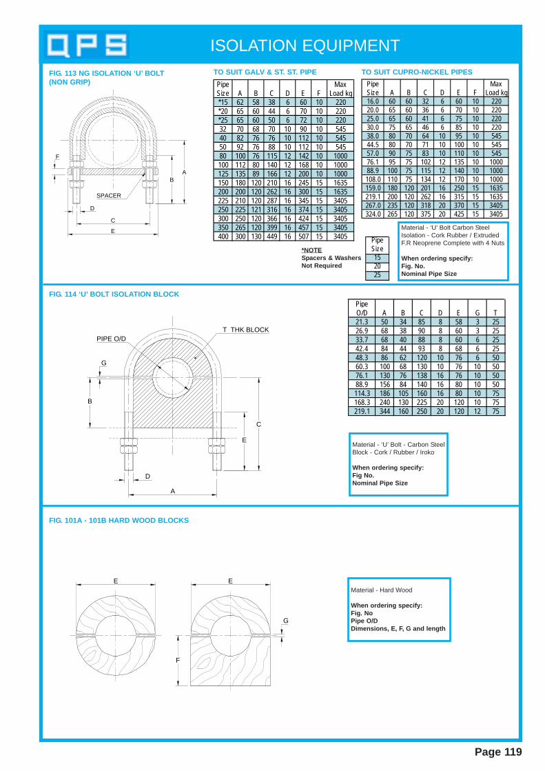
ISOLATION EQUIPMENT
Page 119
Pipe MaxSize A B C D E F Load kg16.0 60 60 32 6 60 10 22020.0 65 60 36 6 70 10 22025.0 65 60 41 6 75 10 22030.0 75 65 46 6 85 10 22038.0 80 70 64 10 95 10 54544.5 80 70 71 10 100 10 54557.0 90 75 83 10 110 10 54576.1 95 75 102 12 135 10 100088.9 100 75 115 12 140 10 1000108.0 110 75 134 12 170 10 1000159.0 180 120 201 16 250 15 1635219.1 200 120 262 16 315 15 1635267.0 235 120 318 20 370 15 3405324.0 265 120 375 20 425 15 3405
Pipe MaxSize A B C D E F Load kg*15 62 58 38 6 60 10 220*20 65 60 44 6 70 10 220*25 65 60 50 6 72 10 22032 70 68 70 10 90 10 54540 82 76 76 10 112 10 54550 92 76 88 10 112 10 54580 100 76 115 12 142 10 1000100 112 80 140 12 168 10 1000125 135 89 166 12 200 10 1000150 180 120 210 16 245 15 1635200 200 120 262 16 300 15 1635225 210 120 287 16 345 15 3405250 225 121 316 16 374 15 3405300 250 120 366 16 424 15 3405350 265 120 399 16 457 15 3405400 300 130 449 16 507 15 3405
Material - ‘U’ Bolt Carbon SteelIsolation - Cork Rubber / ExtrudedF.R Neoprene Complete with 4 Nuts
When ordering specify:Fig. No.Nominal Pipe Size
PipeSize152025
*NOTESpacers & W ashers Not Required
TO SUIT GALV & ST. ST. PIPE TO SUIT CUPRO-NICKEL PIPESFIG. 113 NG ISOLATION ‘U’ BOLT(NON GRIP)
PipeO/D A B C D E G T21.3 50 34 85 8 58 3 2526.9 68 38 90 8 60 3 2533.7 68 40 88 8 60 6 2542.4 84 44 93 8 68 6 2548.3 86 62 120 10 76 6 5060.3 100 68 130 10 76 10 5076.1 130 76 138 16 76 10 5088.9 156 84 140 16 80 10 50114.3 186 105 160 16 80 10 75168.3 240 130 225 20 120 10 75219.1 344 160 250 20 120 12 75
Material - ‘U’ Bolt - Carbon SteelBlock - Cork / Rubber / Iroko
When ordering specify:Fig No.Nominal Pipe Size
FIG. 114 ‘U’ BOLT ISOLATION BLOCK
Material - Hard Wood
When ordering specify:Fig. NoPipe O/D Dimensions, E, F , G and length
FIG. 101A - 101B HARD WOOD BLOCKS
D
E
F
BA
C
SPACER
D
C
A
PIPE O/D
G
B
E
T THK BLOCK
E
G
F
E

ISOLATION EQUIPMENT
Page 120
FIG. 115 ANTI VIBRATION PAD
FIG. 116 ANTI VIBRATION PAD
FIG. 117 SLIDER UNIT
When ordering specify:Figure No.Dimensions A, B, C, D, E, F, G,H
A D
C
B
A D
C
B
A D
C
B
C.S. PLATE
ST.ST PLATE
P.T.F.E. PAD
C.S. PLATE
63
26
17
66
CORK RUBBER PAD
C.S. PLATE
66
2
P.T.F.E. PAD
CORK RUBBER PAD
C.S. PLATE
HE
F
G
When ordering specify:Figure No.Dimensions A, B, C, D
When ordering specify:Figure No.Dimensions A, B, C, D

ISOLATION EQUIPMENT
Page 121
FIG. 109 INSULATED PIPE SADDLE
Pipe DiaO/D Wx T A B C D R D1 D216.0 35x 5 53 68 8.0 M10 11.0 170 27020.0 35x 5 53 68 10.0 M10 13.0 170 27025.0 35x 5 55 70 12.5 M10 15.5 170 21030.0 35x 5 57 72 15.0 M10 18.0 170 21038.0 35x 8 64 82 19.0 M12 22.0 315 28544.5 35x 8 79 97 22.0 M12 25.0 315 28557.0 35x 8 81 99 28.5 M12 31.5 315 20076.1 45x 10 89 113 38.0 M16 41.0 465 33088.9 45x 10 99 123 44.5 M16 47.5 465 280108.0 45x 10 108 132 54.0 M16 57.0 465 220133.0 55x 15 136 166 66.0 M20 69.5 990 410159.0 55x 15 155 185 79.5 M20 82.5 990 410193.7 55x 15 175 205 97.0 M20 100.0 990 315219.1 55x 15 185 215 109.5 M20 112.5 990 315267.0 55x 15 215 245 133.5 M20 136.5 2060 280323.9 55x 15 240 270 162 M20 165 2060 280
Max Load kgDiaNB O/D Wx T A B C D R D1 D215 21.3 35x 5 53 68 10 M10 13.5 170 27020 26.9 35x 5 55 70 13 M10 16.5 170 21025 33.7 35x 5 57 72 16 M10 20.0 170 17532 42.4 35x 8 64 82 20 M12 24.0 315 28540 48.3 35x 8 79 97 23 M12 27.0 315 25050 60.3 35x 8 81 99 29 M12 33.0 315 20065 76.1 45x 10 89 113 36 M16 41.0 465 33080 88.9 45x 10 99 123 43 M16 47.5 465 280
100 114.3 45x 10 108 132 55 M16 60.0 465 220150 168.3 55x 15 160 190 82 M20 87.0 990 410200 219.1 55x 15 185 215 107 M20 112.5 990 315250 273.0 55x 15 215 245 135 M20 139.5 2060 280300 323.9 55x 15 240 270 160 M20 165.0 2060 280
Pipe Size Max Load kg
R
O/D1.5 x T RAD
3 TYP
AB B
A
D DIA BOLTTC
W
10
D2 D2
D1 Direction of loading
MaterialSaddle - Carbon SteelIsolator - Extruded FRNeoprene
When ordering specify:Figure No.Pipe SizeBolt LengthFinish
Surface Finish : Nut s & Bolt s - Bright zinc plated and p assivated to BS1706
FIG. 109 Stainless S teel Pipes FIG. 109 Cupro Nickel Pipes
FIG. 110 CLIP STRIP (C.S)
Q.P.SRef No A B C D ECS-38-6 48 38 9.5 6 5CS-42-6 52 42 9.5 6 5CS-50-6 60 50 9.5 6 5CS-64-6 74 64 9.5 6 5
CS-75-9.5 95 75 13 9.5 10CS-100-9.5 120.0 100 13 9.5 10CS-125-9.5 145 125 13 9.2 10CS-150-12.5 180 150 19 12.5 15
Q.P.SRef No A B *C *D E
CS-38-3 48 38 6 3 5CS-42-3 52 42 6 3 5CS-50-3 60 50 6 3 5CS-64-3 74 64 6 3 5CS-75-3 95 75 6 3 10CS-100-3 120.0 100 6 3 10CS-125-3 145 125 6 3 10CS-150-3 180 150 6 3 15
B EE
C
DA
200 400 600 1000 1200
MaterialExtruded FR NeopreneWhen orderingspecify:Q.P.S Ref No.Length Required
FIG. 110 FIG. 110A*
All sizes are available in thefollowing st andard lengths
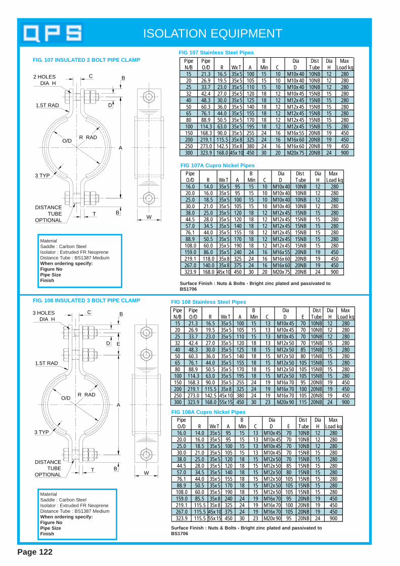
ISOLATION EQUIPMENT
Page 122
Pipe Pipe B Dia Dist Dia MaxN/B O/D R Wx T A Min C D Tube H Load kg15 21.3 16.5 35x 5 100 15 10 M10x 40 10NB 12 28020 26.9 19.5 35x 5 105 15 10 M10x 40 10NB 12 28025 33.7 23.0 35x 5 110 15 10 M10x 40 10NB 12 28032 42.4 27.0 35x 5 120 18 12 M10x 45 15NB 15 28040 48.3 30.0 35x 5 125 18 12 M12x 45 15NB 15 28050 60.3 36.0 35x 5 140 18 12 M12x 45 15NB 15 28065 76.1 44.0 35x 5 155 18 12 M12x 45 15NB 15 28080 88.9 50.5 35x 5 170 18 12 M12x 45 15NB 15 280100 114.3 63.0 35x 5 195 18 12 M12x 45 15NB 15 280150 168.3 90.0 35x 5 255 24 16 M16x 55 20NB 19 450200 219.1 115.5 35x 8 325 24 16 M16x 60 20NB 19 450250 273.0 142.5 35x 8 380 24 16 M16x 60 20NB 19 450300 323.9 168.0 45x 10 450 30 20 M20x 75 20NB 24 900
Pipe B Dia Dist Dia Max O/D R Wx T A Min C D Tube H Load kg16.0 14.0 35x 5 95 15 10 M10x 40 10NB 12 28020.0 16.0 35x 5 95 15 10 M10x 40 10NB 12 28025.0 18.5 35x 5 100 15 10 M10x 40 10NB 12 28030.0 21.0 35x 5 105 15 10 M10x 40 10NB 12 28038.0 25.0 35x 5 120 18 12 M12x 45 15NB 15 28044.5 28.0 35x 5 120 18 12 M12x 45 15NB 15 28057.0 34.5 35x 5 140 18 12 M12x 45 15NB 15 28076.1 44.0 35x 5 155 18 12 M12x 45 15NB 15 28088.9 50.5 35x 5 170 18 12 M12x 45 15NB 15 280108.0 60.0 35x 5 190 18 12 M12x 45 15NB 15 280159.0 86.0 35x 5 240 24 16 M16x 55 20NB 19 450219.1 118.0 35x 8 325 24 16 M16x 60 20NB 19 450267.0 140.0 35x 8 375 24 16 M16x 60 20NB 19 450323.9 168.0 45x 10 450 30 20 M20x 75 20NB 24 900
FIG. 107 INSULATED 2 BOLT PIPE CLAMPFIG 107 Stainless S teel Pipes
FIG 107A Cupro Nickel Pipes
Surface Finish : Nut s & Bolt s - Bright zinc plated and p assivated toBS1706
MaterialSaddle : Carbon SteelIsolator : Extruded FR NeopreneDistance Tube : BS1387 MediumWhen ordering specify:Figure NoPipe SizeFinish
Pipe Pipe B Dia Dist Dia MaxN/B O/D R Wx T A Min C D E Tube H Load kg15 21.3 16.5 35x 5 100 15 13 M10x 45 70 10NB 12 28020 26.9 19.5 35x 5 105 15 13 M10x 45 70 10NB 12 28025 33.7 23.0 35x 5 110 15 13 M10x 45 70 10NB 12 28032 42.4 27.0 35x 5 120 18 13 M12x 50 70 15NB 15 28040 48.3 30.0 35x 5 125 18 15 M12x 50 85 15NB 15 28050 60.3 36.0 35x 5 140 18 15 M12x 50 80 15NB 15 28065 76.1 44.0 35x 5 155 18 15 M12x 50 105 15NB 15 28080 88.9 50.5 35x 5 170 18 15 M12x 50 105 15NB 15 280100 114.3 63.0 35x 5 195 18 15 M12x 50 105 15NB 15 280150 168.3 90.0 35x 5 255 24 19 M16x 70 95 20NB 19 450200 219.1 115.5 35x 8 325 24 19 M16x 70 100 20NB 19 450250 273.0 142.5 45x 10 380 24 19 M16x 70 105 20NB 19 450300 323.9 168.0 55x 15 450 30 23 M20x 90 115 20NB 24 900
Pipe B Dia Dist Dia MaxO/D R Wx T A Min C D E Tube H Load kg16.0 14.0 35x 5 95 15 13 M10x 45 70 10NB 12 28020.0 16.0 35x 5 95 15 13 M10x 45 70 10NB 12 28025.0 18.5 35x 5 100 15 13 M10x 45 70 10NB 12 28030.0 21.0 35x 5 105 15 13 M10x 45 70 15NB 15 28038.0 25.0 35x 5 120 18 15 M12x 50 70 15NB 15 28044.5 28.0 35x 5 120 18 15 M12x 50 85 15NB 15 28057.0 34.5 35x 5 140 18 15 M12x 50 80 15NB 15 28076.1 44.0 35x 5 155 18 15 M12x 50 105 15NB 15 28088.9 50.5 35x 5 170 18 15 M12x 50 105 15NB 15 280108.0 60.0 35x 5 190 18 15 M12x 50 105 15NB 15 280159.0 85.5 35x 8 240 24 19 M16x 70 95 20NB 19 450219.1 115.5 35x 8 325 24 19 M16x 70 100 20NB 19 450267.0 115.5 45x 10 375 24 19 M16x 70 105 20NB 19 450323.9 115.5 55x 15 450 30 23 M20x 90 95 20NB 24 900
FIG 108 Stainless S teel Pipes
FIG 108A Cupro Nickel Pipes
Surface Finish : Nut s & Bolt s - Bright zinc plated and p assivated toBS1706
FIG. 108 INSULATED 3 BOLT PIPE CLAMP
MaterialSaddle : Carbon SteelIsolator : Extruded FR NeopreneDistance Tube : BS1387 MediumWhen ordering specify:Figure NoPipe SizeFinish
O/DR RAD
A
B
BC
W
1.5T RAD D
2 HOLESDIA H
DISTANCETUBE
OPTIONALT
3 TYP
T
3 TYP
O/DR RAD
B
BC
W
1.5T RAD
D
3 HOLESDIA H
E
A
DISTANCETUBE
OPTIONAL
InsulationEquipment
Section 7
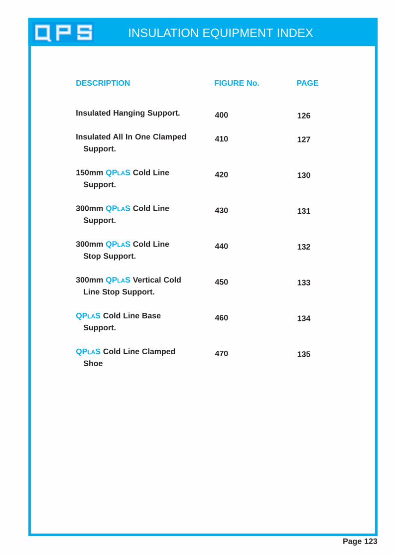
INSULATION EQUIPMENT INDEX
Page 123
Insulated Hanging Support.
Insulated All In One Clamped
Support.
150mm QPLAS Cold Line
Support.
300mm QPLAS Cold Line
Support.
300mm QPLAS Cold Line
Stop Support.
300mm QPLAS Vertical Cold
Line Stop Support.
QPLAS Cold Line Base
Support.
QPLAS Cold Line Clamped
Shoe
400
410
420
430
440
450
460
470
126
127
130
131
132
133
134
135
DESCRIPTION FIGURE No. PAGE

INSULATION EQUIPMENT INDEX
Page 124
INDEX
FIG.No. DESCRIPTIONPageNo. PICTORIAL
400
410
420
430
440
450
460
470
150mm QPLASCold LineSupport
300mm QPLASCold LineSupport
300mm QPLASCold Line Stop
Support
300mm QPLASVertical Cold
Line StopSupport
QPLAS ColdLine Clamped
Shoe
InsulatedHangingSupport
Insulated all inOne Clamped
Support
130
127
131
132
133
134
135
126
QPLAS ColdLine BaseSupport
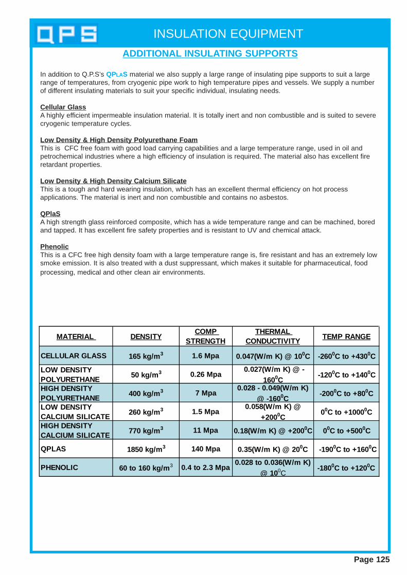
INSULATION EQUIPMENT
Page 125
ADDITIONAL INSULATING SUPPORTS
In addition to Q.P.S’s QPLAS material we also supply a large range of insulating pipe supports to suit a largerange of temperatures, from cryogenic pipe work to high temperature pipes and vessels. We supply a numberof different insulating materials to suit your specific individual, insulating needs.
Cellular GlassA highly efficient impermeable insulation material. It is totally inert and non combustible and is suited to severecryogenic temperature cycles.
Low Density & High Density Polyurethane FoamThis is CFC free foam with good load carrying capabilities and a large temperature range, used in oil andpetrochemical industries where a high efficiency of insulation is required. The material also has excellent fireretardant properties.
Low Density & High Density Calcium SilicateThis is a tough and hard wearing insulation, which has an excellent thermal efficiency on hot processapplications. The material is inert and non combustible and contains no asbestos.
QPlaSA high strength glass reinforced composite, which has a wide temperature range and can be machined, boredand tapped. It has excellent fire safety properties and is resistant to UV and chemical attack.
PhenolicThis is a CFC free high density foam with a large temperature range is, fire resistant and has an extremely lowsmoke emission. It is also treated with a dust suppressant, which makes it suitable for pharmaceutical, foodprocessing, medical and other clean air environments.
MATERIAL DENSITYCOMP
STRENGTHTHERMAL
CONDUCTIVITYTEMP RANGE
CELLULAR GLASS 165 kg/m3 1.6 Mpa 0.047(W/m K) @ 100C -2600C to +4300C
LOW DENSITY POLYURETHANE
50 kg/m3 0.26 Mpa 0.027(W/m K) @ -
1600C-1200C to +1400C
HIGH DENSITY POLYURETHANE
400 kg/m3 7 Mpa0.028 - 0.049(W/m K)
@ -1600C-2000C to +800C
LOW DENSITY CALCIUM SILICATE
260 kg/m3 1.5 Mpa0.058(W/m K) @
+2000C 00C to +10000C
HIGH DENSITY CALCIUM SILICATE
770 kg/m3 11 Mpa 0.18(W/m K) @ +2000C 00C to +5000C
QPLAS 1850 kg/m3 140 Mpa 0.35(W/m K) @ 200C -1900C to +1600C
PHENOLIC 60 to 160 kg/m3 0.4 to 2.3 Mpa0.028 to 0.036(W/m K)
@ 100C-1800C to +1200C
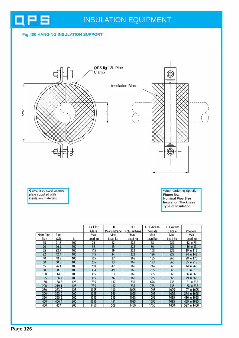
INSULATION EQUIPMENT
Page 126
Fig 400 HANGING INSULA TION SUPPORT
When Ordering Specify:Figure No.Nominal Pipe SizeInsulation ThicknessType of Insulation.
QPS fig 12L Pipe Clamp
Insulation Block
L
I/D
O/D
Cellular LD HD LD Calcium HD Calcium Glass Poly urethane Poly urethane Silicate Silicate Phenolic
Nom Pipe Pipe Max Max Max Max Max MaxSize O/D L Load kg Load kg Load kg Load kg Load kg Load kg15 21.3 100 73 12 222 68 222 12 to 7520 26.9 100 92 15 222 86 222 16 to 9525 33.7 100 115 19 222 108 222 19 to 11932 42.4 100 145 24 222 136 222 24 to 14940 48.3 100 165 27 365 155 365 28 to 17050 60.3 100 206 33 365 193 365 35 to 21365 76.1 100 260 42 365 244 365 44 to 26880 88.9 100 304 49 365 285 365 51 to 313100 114.3 100 365 63 365 365 365 66 to 365125 136.7 100 365 76 365 365 365 79 to 365150 168.3 125 735 117 735 674 735 121 to 735200 219.1 125 735 152 735 735 735 158 to 735250 273.0 125 1095 190 1095 1095 1095 197 to 1095300 323.9 200 1095 360 1095 1095 1095 374 to 1095350 355.6 200 1095 395 1095 1095 1095 410 to 1095400 406.4 200 1095 451 1095 1095 1095 469 to 1095450 457 200 1450 508 1450 1450 1450 527 to 1450
Galvanised steel wrapperplate supplied withinsulation materials.
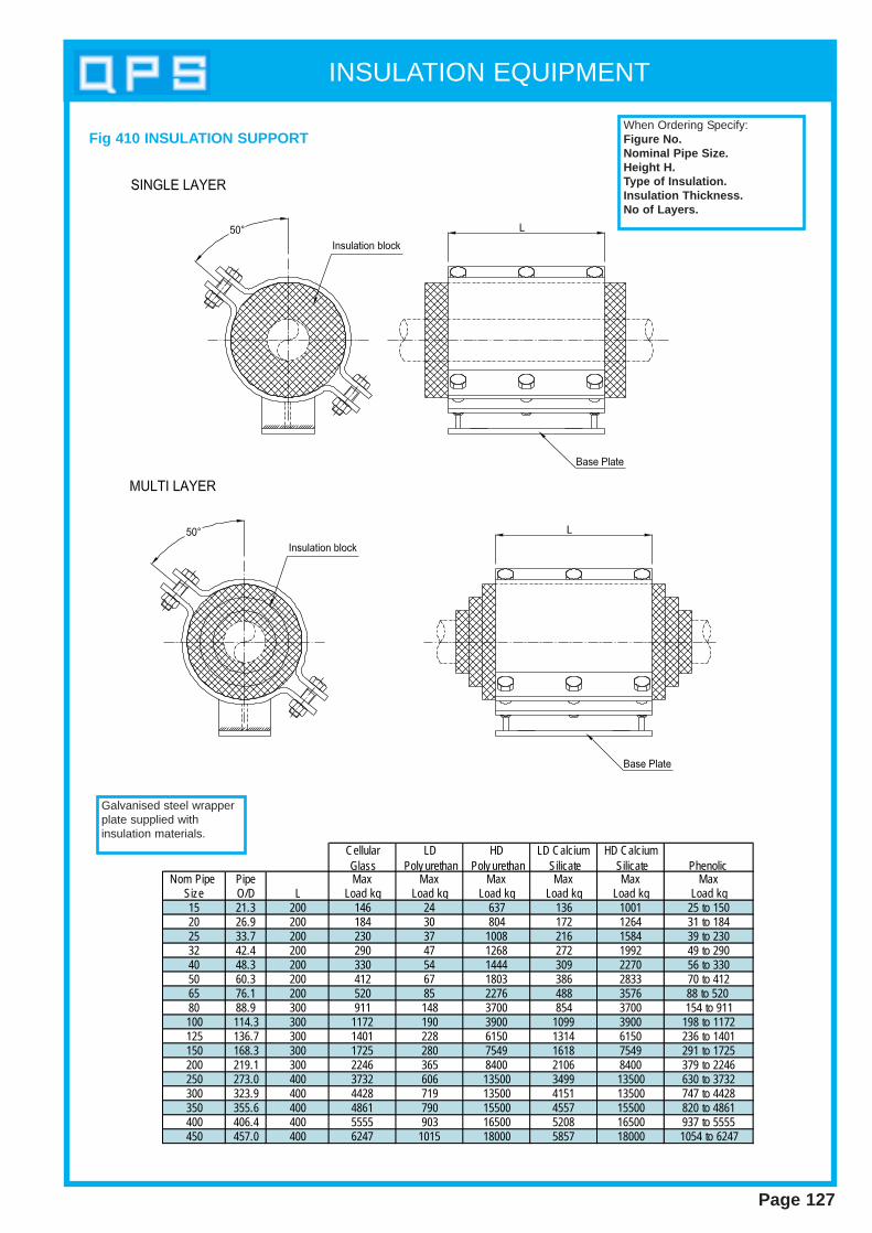
INSULATION EQUIPMENT
Page 127
Cellular LD HD LD Calcium HD Calcium Glass Poly urethan Poly urethan Silicate Silicate Phenolic
Nom Pipe Pipe Max Max Max Max Max MaxSize O/D L Load kg Load kg Load kg Load kg Load kg Load kg15 21.3 200 146 24 637 136 1001 25 to 15020 26.9 200 184 30 804 172 1264 31 to 18425 33.7 200 230 37 1008 216 1584 39 to 23032 42.4 200 290 47 1268 272 1992 49 to 29040 48.3 200 330 54 1444 309 2270 56 to 33050 60.3 200 412 67 1803 386 2833 70 to 41265 76.1 200 520 85 2276 488 3576 88 to 520 80 88.9 300 911 148 3700 854 3700 154 to 911100 114.3 300 1172 190 3900 1099 3900 198 to 1172125 136.7 300 1401 228 6150 1314 6150 236 to 1401150 168.3 300 1725 280 7549 1618 7549 291 to 1725200 219.1 300 2246 365 8400 2106 8400 379 to 2246250 273.0 400 3732 606 13500 3499 13500 630 to 3732300 323.9 400 4428 719 13500 4151 13500 747 to 4428350 355.6 400 4861 790 15500 4557 15500 820 to 4861400 406.4 400 5555 903 16500 5208 16500 937 to 5555450 457.0 400 6247 1015 18000 5857 18000 1054 to 6247
Fig 410 INSULA TION SUPPORTWhen Ordering Specify:Figure No.Nominal Pipe Size.Height H.Type of Insulation.Insulation Thickness.No of Layers.
Galvanised steel wrapperplate supplied withinsulation materials.

INSULATION EQUIPMENT
Page 128
QPLAS Insulating Support s
QPS Description
The insulation we use in the blocks and pipe shoes is moulded from a high strength glassreinforced composite and is referred to as QPLAS.
The QPLAS material has a number of advantages over other materials such as steel and wood, inthat no maintenance is required after installation, as it requires no painting or special coatings . The QPLASmaterial absorbs no moisture and suffers no corrosive effects.The versatility of this material means that it canbe machined, bored, and tapped so that it can incorporate steel supports and fixings. QPLAS is alsoextremely safe as it has excellent fire safety properties tested to BS 476 part 5&6 (1968) and is classified“Not Easily Ignit able”.
Material Benefit s
Material Properties & T echnical Information
• Worldwide installations (in diverse climates, conditions & applications)• High strength in all directions• Robust and durable• Thermal & electrical insulator• Dimensionally stable• Fire retardant• Flame resistant• Corrosion free• Resistant to UV and chemical attack• Non-hazardous• Wide temperature range• Maintenance free• No significant moisture absorption• No protective coating required• Product life expectancy in excess of 30 years
Compressive Strength 20°C (MPa) 140Compressive Strength 100°C (MPa) 50Compressive Strength 150°C (MPa) 30Tensile Strength 20°C (MPa) 45Shear Strength 20°C (MPa) 50Flexural Strength 20°C (MPa) 90Density (g/cm3) 1.85Elastic Modulus (GPa) 14Thermal Conductivity (W/m K) at 20°C 0.35Impact Strength 20°C (kJ/ m2) 25Electrical Strength MV/m 9.5Volume resistivity TWm 1.5Surface resistivity TW 1000Upper operating temperature (°C) 160Lower operating temperature (°C) –190
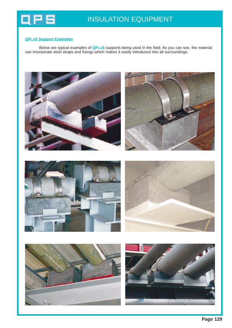
INSULATION EQUIPMENT
Page 129
QPLAS Support Examples
Below are typical examples of QPLAS supports being used in the field. As you can see, the materialcan incorporate steel straps and fixings which makes it easily introduced into all surroundings.
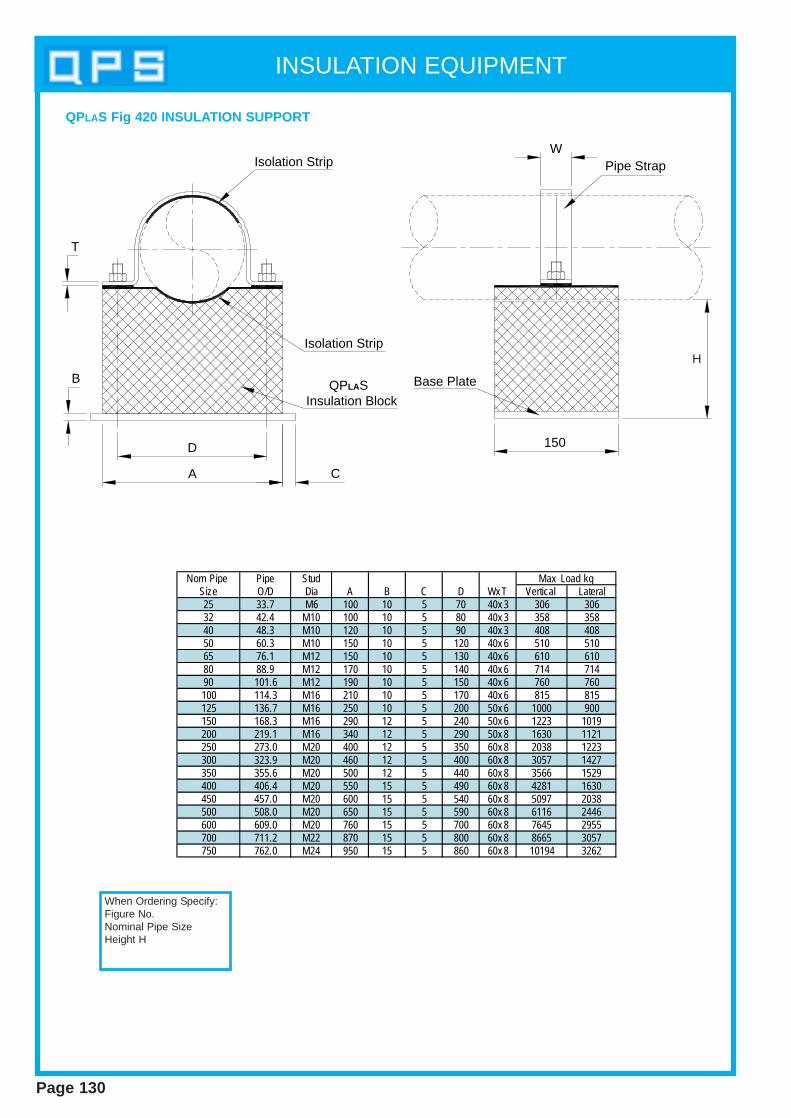
D
A
T
C
WIsolation Strip
Isolation Strip
Base Plate QPLAS Insulation Block
Pipe Strap
150
B
H
Nom Pipe Pipe StudSize O/D Dia A B C D Wx T Vertical Lateral25 33.7 M6 100 10 5 70 40x 3 306 30632 42.4 M10 100 10 5 80 40x 3 358 35840 48.3 M10 120 10 5 90 40x 3 408 40850 60.3 M10 150 10 5 120 40x 6 510 51065 76.1 M12 150 10 5 130 40x 6 610 61080 88.9 M12 170 10 5 140 40x 6 714 71490 101.6 M12 190 10 5 150 40x 6 760 760100 114.3 M16 210 10 5 170 40x 6 815 815125 136.7 M16 250 10 5 200 50x 6 1000 900150 168.3 M16 290 12 5 240 50x 6 1223 1019200 219.1 M16 340 12 5 290 50x 8 1630 1121250 273.0 M20 400 12 5 350 60x 8 2038 1223300 323.9 M20 460 12 5 400 60x 8 3057 1427350 355.6 M20 500 12 5 440 60x 8 3566 1529400 406.4 M20 550 15 5 490 60x 8 4281 1630450 457.0 M20 600 15 5 540 60x 8 5097 2038500 508.0 M20 650 15 5 590 60x 8 6116 2446600 609.0 M20 760 15 5 700 60x 8 7645 2955700 711.2 M22 870 15 5 800 60x 8 8665 3057750 762.0 M24 950 15 5 860 60x 8 10194 3262
Max Load kg
QPLAS Fig 420 INSULA TION SUPPORT
When Ordering Specify:Figure No.Nominal Pipe SizeHeight H
INSULATION EQUIPMENT
Page 130
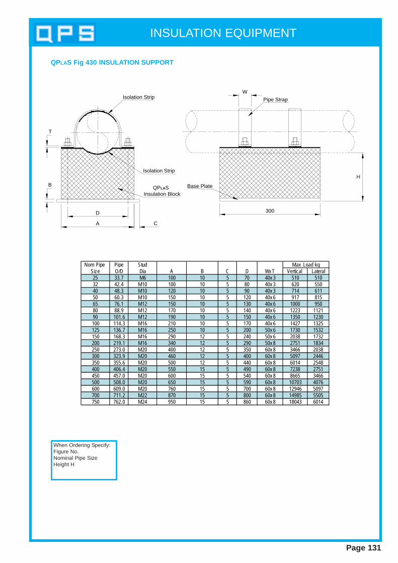
D
A
T
C
WIsolation Strip
Isolation Strip
Base Plate QPLAS Insulation Block
Pipe Strap
300
B
H
QPLAS Fig 430 INSULA TION SUPPORT
Nom Pipe Pipe StudSize O/D Dia A B C D Wx T Vertical Lateral25 33.7 M6 100 10 5 70 40x 3 510 51032 42.4 M10 100 10 5 80 40x 3 620 55040 48.3 M10 120 10 5 90 40x 3 714 61150 60.3 M10 150 10 5 120 40x 6 917 81565 76.1 M12 150 10 5 130 40x 6 1000 95080 88.9 M12 170 10 5 140 40x 6 1223 112190 101.6 M12 190 10 5 150 40x 6 1350 1230100 114.3 M16 210 10 5 170 40x 6 1427 1325125 136.7 M16 250 10 5 200 50x 6 1730 1532150 168.3 M16 290 12 5 240 50x 6 2038 1732200 219.1 M16 340 12 5 290 50x 8 2751 1834250 273.0 M20 400 12 5 350 60x 8 3466 2038300 323.9 M20 460 12 5 400 60x 8 5097 2446350 355.6 M20 500 12 5 440 60x 8 6014 2548400 406.4 M20 550 15 5 490 60x 8 7238 2751450 457.0 M20 600 15 5 540 60x 8 8665 3466500 508.0 M20 650 15 5 590 60x 8 10703 4076600 609.0 M20 760 15 5 700 60x 8 12946 5097700 711.2 M22 870 15 5 800 60x 8 14985 5505750 762.0 M24 950 15 5 860 60x 8 18043 6014
Max Load kg
When Ordering Specify:Figure No.Nominal Pipe SizeHeight H
INSULATION EQUIPMENT
Page 131
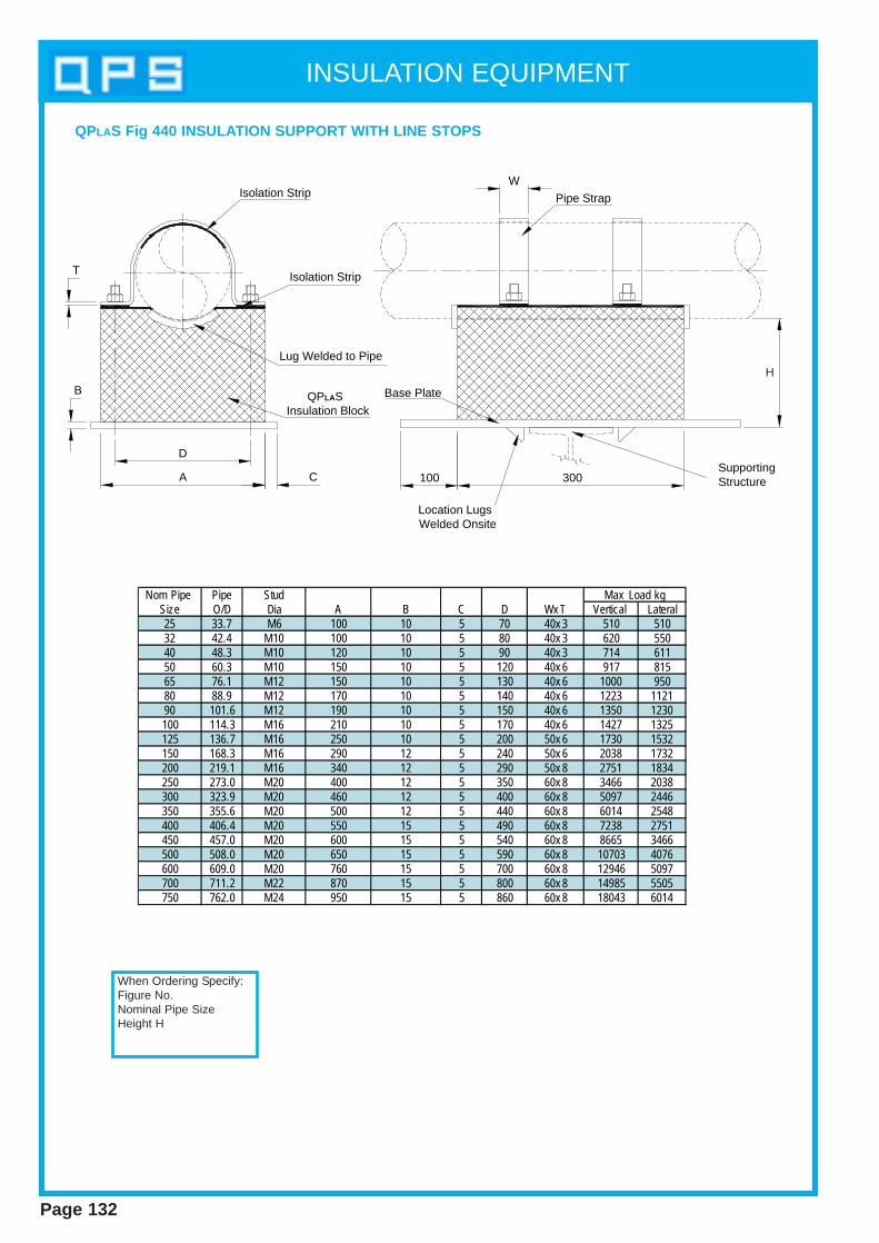
INSULATION EQUIPMENT
Page 132
QPLAS Fig 440 INSULA TION SUPPORT WITH LINE STOPS
D
A
T
C
WIsolation Strip
Isolation Strip
Base Plate QPLAS Insulation Block
Pipe Strap
300100Supporting Structure
Location Lugs Welded Onsite
Lug Welded to Pipe
B
H
Nom Pipe Pipe StudSize O/D Dia A B C D Wx T Vertical Lateral25 33.7 M6 100 10 5 70 40x 3 510 51032 42.4 M10 100 10 5 80 40x 3 620 55040 48.3 M10 120 10 5 90 40x 3 714 61150 60.3 M10 150 10 5 120 40x 6 917 81565 76.1 M12 150 10 5 130 40x 6 1000 95080 88.9 M12 170 10 5 140 40x 6 1223 112190 101.6 M12 190 10 5 150 40x 6 1350 1230100 114.3 M16 210 10 5 170 40x 6 1427 1325125 136.7 M16 250 10 5 200 50x 6 1730 1532150 168.3 M16 290 12 5 240 50x 6 2038 1732200 219.1 M16 340 12 5 290 50x 8 2751 1834250 273.0 M20 400 12 5 350 60x 8 3466 2038300 323.9 M20 460 12 5 400 60x 8 5097 2446350 355.6 M20 500 12 5 440 60x 8 6014 2548400 406.4 M20 550 15 5 490 60x 8 7238 2751450 457.0 M20 600 15 5 540 60x 8 8665 3466500 508.0 M20 650 15 5 590 60x 8 10703 4076600 609.0 M20 760 15 5 700 60x 8 12946 5097700 711.2 M22 870 15 5 800 60x 8 14985 5505750 762.0 M24 950 15 5 860 60x 8 18043 6014
Max Load kg
When Ordering Specify:Figure No.Nominal Pipe SizeHeight H
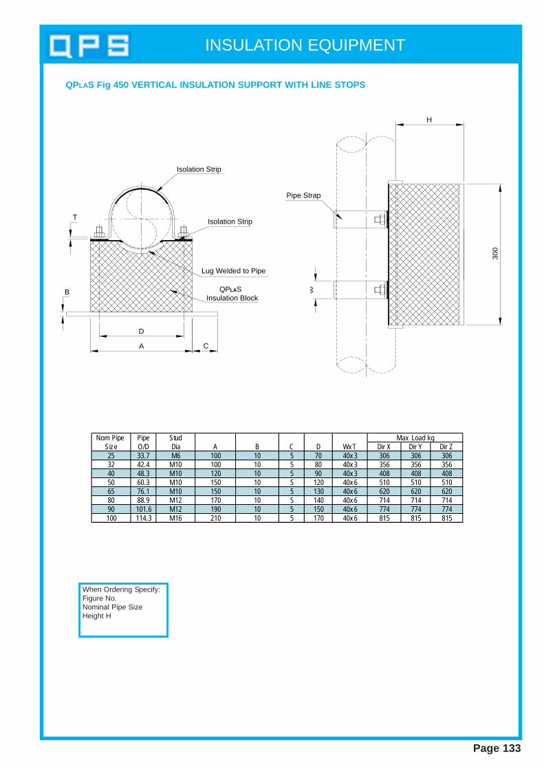
INSULATION EQUIPMENT
Page 133
Nom Pipe Pipe StudSize O/D Dia A B C D Wx T Dir X Dir Y Dir Z25 33.7 M6 100 10 5 70 40x 3 306 306 30632 42.4 M10 100 10 5 80 40x 3 356 356 35640 48.3 M10 120 10 5 90 40x 3 408 408 40850 60.3 M10 150 10 5 120 40x 6 510 510 51065 76.1 M10 150 10 5 130 40x 6 620 620 62080 88.9 M12 170 10 5 140 40x 6 714 714 71490 101.6 M12 190 10 5 150 40x 6 774 774 774100 114.3 M16 210 10 5 170 40x 6 815 815 815
Max Load kg
QPLAS Fig 450 VERTICAL INSULATION SUPPORT WITH LINE STOPS
D
A
T
C
W
Isolation Strip
Isolation Strip
QPLAS Insulation Block
Pipe Strap
300
H
Lug Welded to Pipe
B
When Ordering Specify:Figure No.Nominal Pipe SizeHeight H

INSULATION EQUIPMENT
Page 134
QPLAS Fig 460 INSULA TION SUPPORT
Plate BlockNom Pipe Pipe Trunnion Dimensions Dimensions
Size O/D Nom Size Ax Ax B Cx Cx H Number Size Vertical Laterial25 33.7 20 140x 140x 10 100x 100x 90 4 M8x 30 1529 51032 42.4 25 140x 140x 10 100x 100x 90 4 M8x 30 1529 51040 48.3 32 140x 140x 10 100x 100x 90 4 M8x 30 1529 51050 60.3 40 140x 140x 10 100x 100x 90 4 M8x 30 1529 51065 76.1 40 140x 140x 10 100x 100x 90 4 M8x 30 1529 51080 88.9 50 140x 140x 10 100x 100x 90 4 M8x 30 1529 51090 101.6 80 190x 190x 12 150x 150x 88 4 M8x 30 1529 510100 114.3 80 190x 190x 12 150x 150x 88 4 M10x 30 3668 1121125 136.7 100 190x 190x 12 150x 150x 88 4 M10x 30 3668 1121150 168.3 100 190x 190x 12 150x 150x 88 4 M10x 30 3668 1121200 219.1 150 190x 190x 12 150x 150x 88 4 M10x 30 3668 1121250 273.0 200 300x 300x 15 260x 260x 85 6 M10x 40 9171 1936300 323.9 250 300x 300x 15 260x 260x 85 6 M10x 40 9171 1936350 355.6 300 350x 350x 15 310x 310x 85 6 M10x 40 17323 2038400 406.4 350 400x 400x 15 360x 360x 85 6 M12x 40 23445 2345450 457.0 400 440x 440x 15 400x 400x 85 6 M12x 40 23445 2345500 508.0 450 500x 500x 15 460x 460x 85 6 M12x 40 23445 2345600 609.0 500 600x 600x 15 560x 560x 85 6 M12x 40 23445 2345
Max Load kgPlate Fix ings(Per Plate)
When Ordering Specify:Figure No.Nominal Pipe SizeHeight H
C
A
TrunnionTop Plate
QPLAS Insulation Block
Base Plate
B
H
B
A C

INSULATION EQUIPMENT
Page 135
QPLAS Fig 470 INSULA TION SUPPORT
Nom Pipe Pipe Stud Vertical Vertical Size O/D Dia A B C Dow nw ard Upw ards Laterial25 33.7 M12 100 10 10 5921 3159 428032 42.4 M12 100 10 10 5921 3159 428040 48.3 M12 100 10 10 5921 3159 428050 60.3 M12 100 10 10 5921 3159 428065 76.1 M12 100 10 10 5921 3159 428080 88.9 M12 100 10 10 5921 3159 428090 101.6 M12 100 10 10 5921 3159 4280100 114.3 M16 100 10 10 7849 3159 4280125 136.7 M16 100 10 10 7849 3159 4280150 168.3 M20 100 12 10 7849 3159 4280200 219.1 M20 100 12 10 7849 3159 4280250 273.0 M24 150 12 10 28542 3159 4280300 323.9 M24 150 12 10 28542 3159 4280350 355.6 M24 200 12 10 36391 3159 4280400 406.4 M24 200 15 10 45872 3159 4280450 457.0 M24 250 15 10 45872 3159 4280500 508.0 M24 250 15 10 45872 3159 4280600 609.0 M30 250 15 10 45872 3159 4280
Max Load kg
When Ordering Specify:Figure No.Nominal Pipe SizeHeight H
Page 136
NOTES
FabricatedStructural S teelwork
Section 8
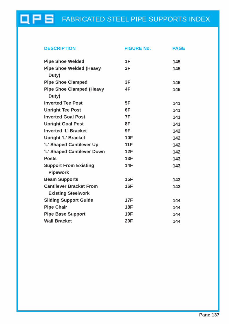
FABRICATED STEEL PIPE SUPPORTS INDEX
Page 137
Pipe Shoe Welded
Pipe Shoe Welded (Heavy
Duty)
Pipe Shoe Clamped
Pipe Shoe Clamped (Heavy
Duty)
Inverted Tee Post
Upright Tee Post
Inverted Goal Post
Upright Goal Post
Inverted ‘L’ Bracket
Upright ‘L’ Bracket
‘L’ Shaped Cantilever Up
‘L’ Shaped Cantilever Down
Posts
Support From Existing
Pipework
Beam Supports
Cantilever Bracket From
Existing Steelwork
Sliding Support Guide
Pipe Chair
Pipe Base Support
Wall Bracket
1F
2F
3F
4F
5F
6F
7F
8F
9F
10F
11F
12F
13F
14F
15F
16F
17F
18F
19F
20F
145
145
146
146
141
141
141
141
142
142
142
142
143
143
143
143
144
144
144
144
DESCRIPTION FIGURE No. PAGE
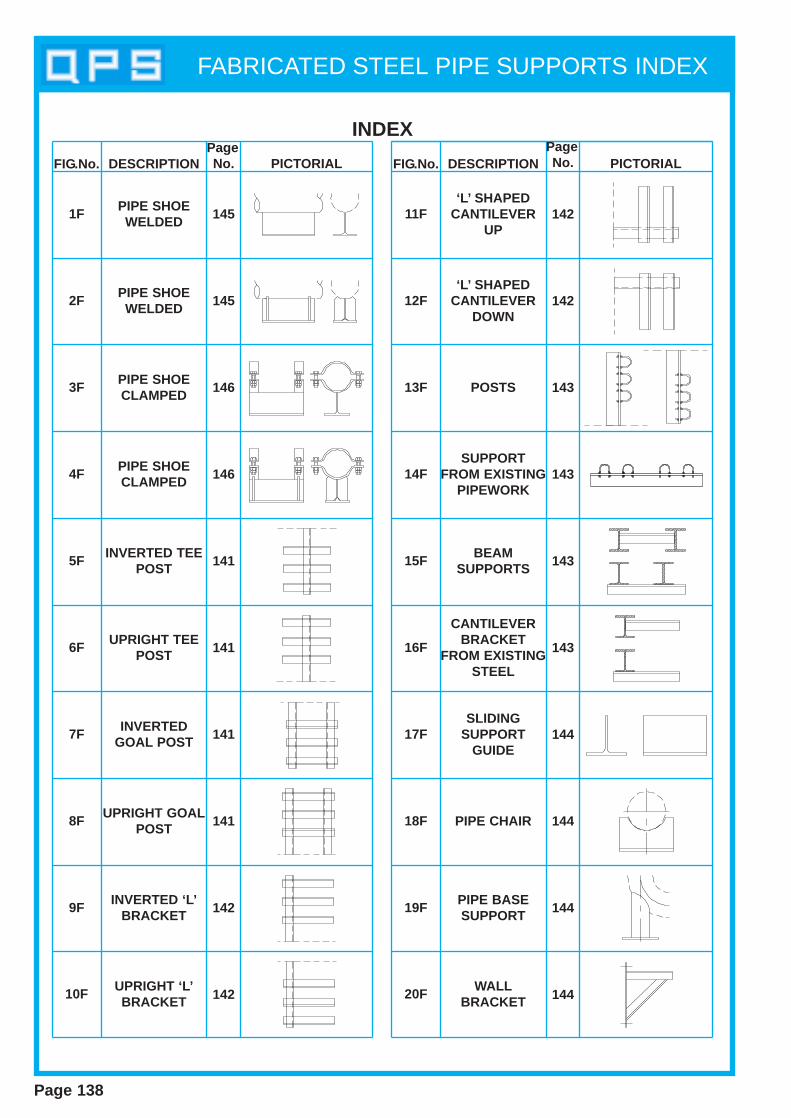
FABRICATED STEEL PIPE SUPPORTS INDEX
INDEX
FIG.No. DESCRIPTIONPageNo. PICTORIAL FIG.No. DESCRIPTION
PageNo. PICTORIAL
1F
2F
3F
4F
5F
6F
7F
8F
9F
10F
11F
12F
13F
14F
15F
16F
17F
18F
19F
20F
PIPE SHOEWELDED
PIPE SHOEWELDED
PIPE SHOECLAMPED
PIPE SHOECLAMPED
INVERTED TEEPOST
UPRIGHT TEEPOST
INVERTEDGOAL POST
UPRIGHT GOALPOST
INVERTED ‘L’BRACKET
UPRIGHT ‘L’BRACKET
‘L’ SHAPEDCANTILEVER
UP
‘L’ SHAPEDCANTILEVER
DOWN
POSTS
SUPPORTFROM EXISTING
PIPEWORK
BEAMSUPPORTS
CANTILEVERBRACKET
FROM EXISTINGSTEEL
SLIDINGSUPPORT
GUIDE
PIPE CHAIR
PIPE BASESUPPORT
WALLBRACKET
145
145
146
146
141
141
141
141
142
142
142
142
143
143
143
143
144
144
144
144
Page 138
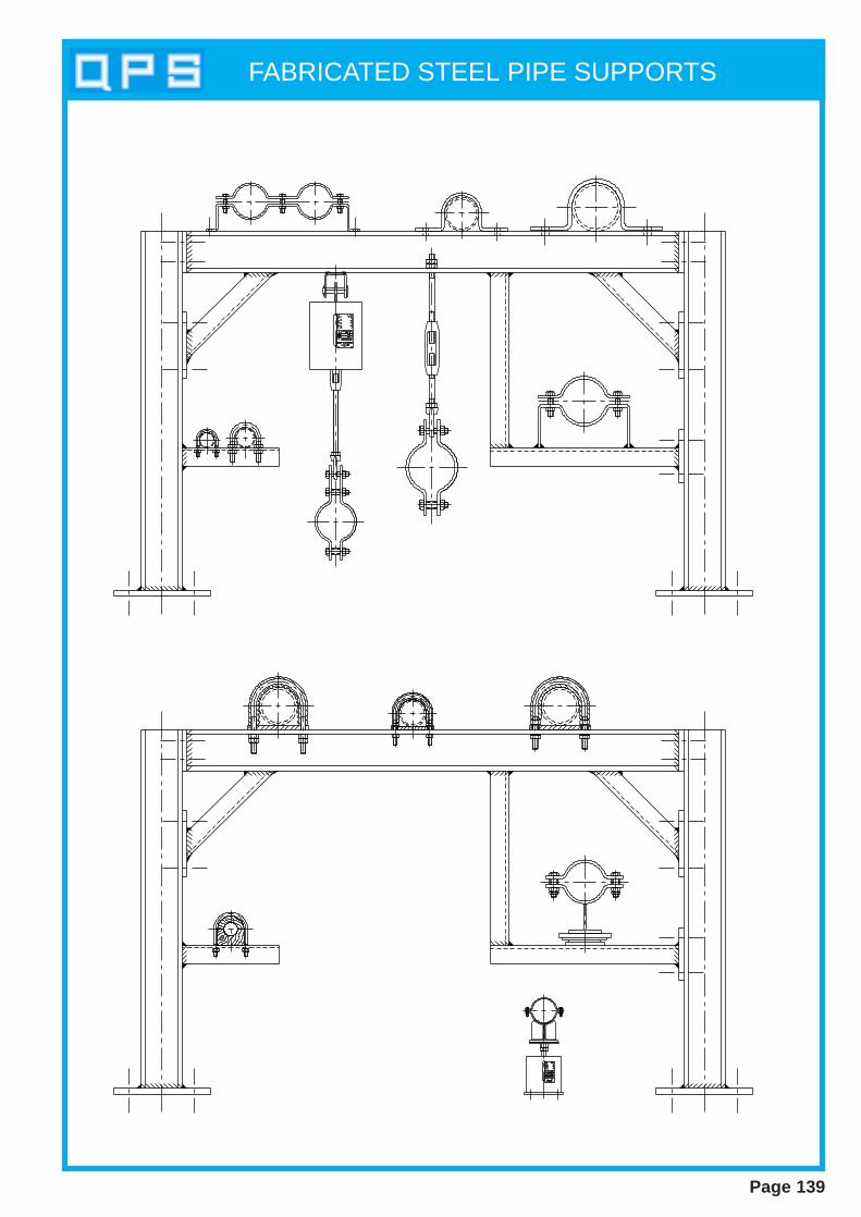
FABRICATED STEEL PIPE SUPPORTS
Page 139
FABRICATED STEEL PIPE SUPPORTS
Page 140
Quality Pipe Supports are specialists in fabrication steelwork. The design anddetail of small and large structural frames can be carried out by our engineeringdepartment which can offer practical advice and assistance in all areas.
MATERIALSAll structural steel used is of high quality. Quality Pipe Supports offer a widerange of steel including carbon steel, alloy steel, stainless steel and lowtemperature steels. All steels will have full mechanical and chemical testcertificates. When requested, full traceability of material will be given.
QUALITY ASSURANCEQuality Pipe Supports documented Quality Assurance Manual and Proceduresare written to comply with ISO 9001. Our quality manual is available forinspection on request and we welcome Quality Audits to verify our system.Where contracts require, a specific quality plan can be submitted andimplemented into our workshops. Comprehensive material traceability is astandard function on all incoming goods. This can be achieved in all stages ofmanufacture on request.
SURFACE FINISHESAll standard surface preparations and finishes are available to steelwork.Shotblasting is carried out to Swedish standard SA 2.5. Alternative surfacepreparation can be achieved on request. We offer a large range of paintingsystems to suit all types of environments. Our standard finishes are:
Zinc Electro PlatingHot Dip Galvanizing Sherardizing Cadmium Plating
l EXPERIENCE OF FABRICATIONS IN ALL STANDARD SECTIONS.
ll HIGH QUALITY CARBON STEEL, LOW TEMP STEEL, ALLOYS ANDSTAINLESS STEEL.
ll APPROVED WELD PROCEDURES, QUALIFIED WELDERS.
ll MANUFACTURED TO ISO 9001 REQUIREMENTS.
ll FULL MATERIAL TRACEABILITY WHERE REQUIRED.
ll INDIVIDUAL QUALITY PLAN WHEN REQUESTED.
ll PAINTING, GALVANIZING, PLASTIC COATING FINISHES AVAILABLE.
ll DESIGN FACILITIES GIVING PRACTICAL ADVICE ON HAND.

FABRICATED STEEL PIPE SUPPORTS
Page 141
FIG. 5F INVERTED TEE POST FIG. 6F UPRIGHT TEE POST
FIG. 7F INVERTED GOAL POST FIG. 8F UPRIGHT GOAL POST
When ordering specify:Support TypeMaterial SectionsAll dimensions
When ordering specify:Support TypeMaterial SectionsAll dimensions
When ordering specify:Support TypeMaterial SectionsAll dimensions
When ordering specify:Support TypeMaterial SectionsAll dimensions
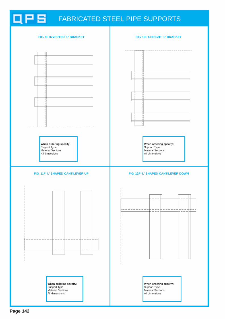
FABRICATED STEEL PIPE SUPPORTS
Page 142
FIG. 9F INVERTED ‘L’ BRACKET FIG. 10F UPRIGHT ‘L’ BRACKET
FIG. 11F ‘L’ SHAPED CANTILEVER UP FIG. 12F ‘L’ SHAPED CANTILEVER DOWN
When ordering specify:Support TypeMaterial SectionsAll dimensions
When ordering specify:Support TypeMaterial SectionsAll dimensions
When ordering specify:Support TypeMaterial SectionsAll dimensions
When ordering specify:Support TypeMaterial SectionsAll dimensions
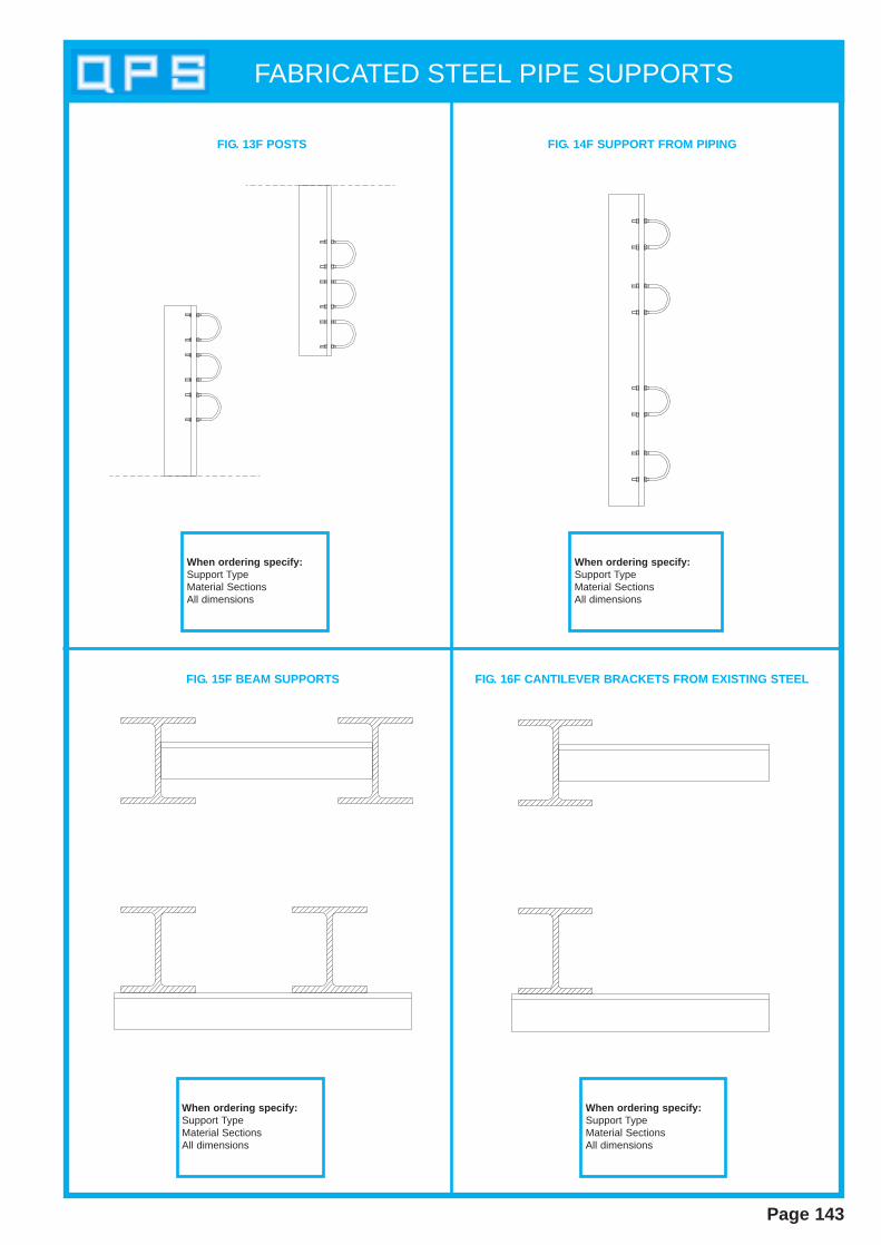
FABRICATED STEEL PIPE SUPPORTS
Page 143
FIG. 13F POSTS FIG. 14F SUPPORT FROM PIPING
FIG. 15F BEAM SUPPORTS FIG. 16F CANTILEVER BRACKETS FROM EXISTING STEEL
When ordering specify:Support TypeMaterial SectionsAll dimensions
When ordering specify:Support TypeMaterial SectionsAll dimensions
When ordering specify:Support TypeMaterial SectionsAll dimensions
When ordering specify:Support TypeMaterial SectionsAll dimensions
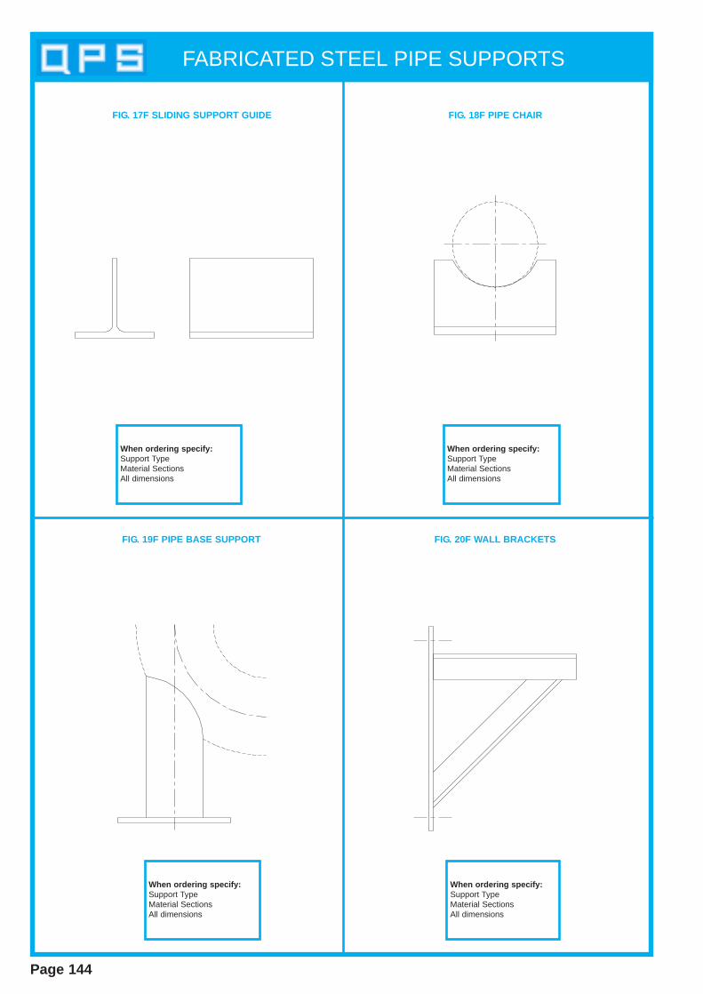
FABRICATED STEEL PIPE SUPPORTS
Page 144
FIG. 17F SLIDING SUPPORT GUIDE FIG. 18F PIPE CHAIR
FIG. 19F PIPE BASE SUPPORT FIG. 20F WALL BRACKETS
When ordering specify:Support TypeMaterial SectionsAll dimensions
When ordering specify:Support TypeMaterial SectionsAll dimensions
When ordering specify:Support TypeMaterial SectionsAll dimensions
When ordering specify:Support TypeMaterial SectionsAll dimensions

FABRICATED STEEL PIPE SUPPORTS
Page 145
FIG. 1F PIPE SHOE
FIG. 2F PIPE SHOE
When ordering specify:Fig. No.Pipe SizeLength LHeight HWidth WMaterial Section
When ordering specify:Fig. No.Pipe SizeLength LHeight HWidth WMaterial Section
TEE SECTION CUTFROM UNIVERSAL BEAM
W
USE UP TOPIPE SIZE 150 N/B
H
L
TEE SECTION CUTFROM UNIVERSAL BEAM
W
USE UP TOPIPE SIZE 350 N/B
L
8
H
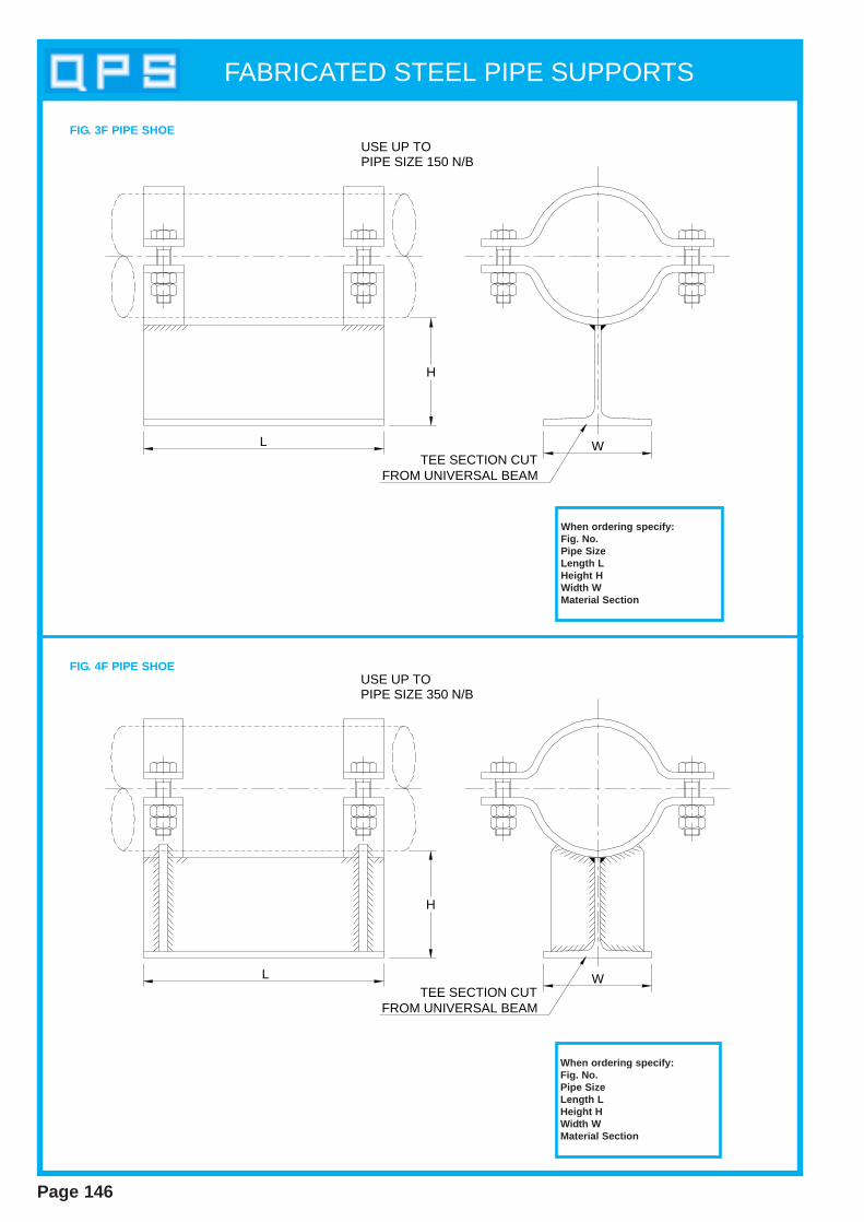
FABRICATED STEEL PIPE SUPPORTS
Page 146
When ordering specify:Fig. No.Pipe SizeLength LHeight HWidth WMaterial Section
When ordering specify:Fig. No.Pipe SizeLength LHeight HWidth WMaterial Section
FIG. 4F PIPE SHOE
FIG. 3F PIPE SHOE
TEE SECTION CUTFROM UNIVERSAL BEAM
W
USE UP TOPIPE SIZE 150 N/B
H
L
TEE SECTION CUTFROM UNIVERSAL BEAM
W
USE UP TOPIPE SIZE 350 N/B
H
L
Staircases W alkways& Balustrading
Section 9
STAIRCASES, WALKWAYS & BALUSTRADING
Page 147
Quality Pipe Supports (Q.P.S) Ltd , offer a range of access products tothe construction industry. A comprehensive service is offered from sitemeasurement to installation.
Our comprehensive design and drawing facilities can handle large orsmall contracts. Experienced designers can give practical advice andassistance in the design of your requirements.
MaterialsOur experience enables us to confidently manufacture in a wide range ofmaterials. From high quality carbon steels, low temperature steels, alloysteels and stainless steels. All welding is performed by qualified weldersto approved procedures.
With a total package of design, manufacture and strict quality assurancewe are able to provide a highly efficient service to our customers.
Quality AssuranceAll manufacturing is in accordance with BS EN ISO9001:2000. Our fullydocumented systems are open to Q.A Audits. All materials used are covered by full chemical and mechanical test certificates where available.Where no certification is available (nuts, bolts, etc) a certificate of conformity is provided.
ll STAIRCASES
ll LADDERS
ll STEELWORK
ll HANDRAILS
ll BALUSTRADES
ll FLOORING
ll STEEL ACCESS DOORS
ll WALKWAYS
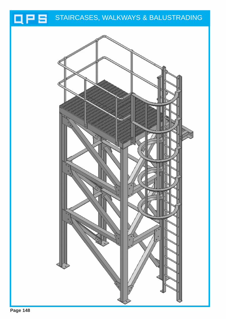
STAIRCASES, WALKWAYS & BALUSTRADING
Page 148
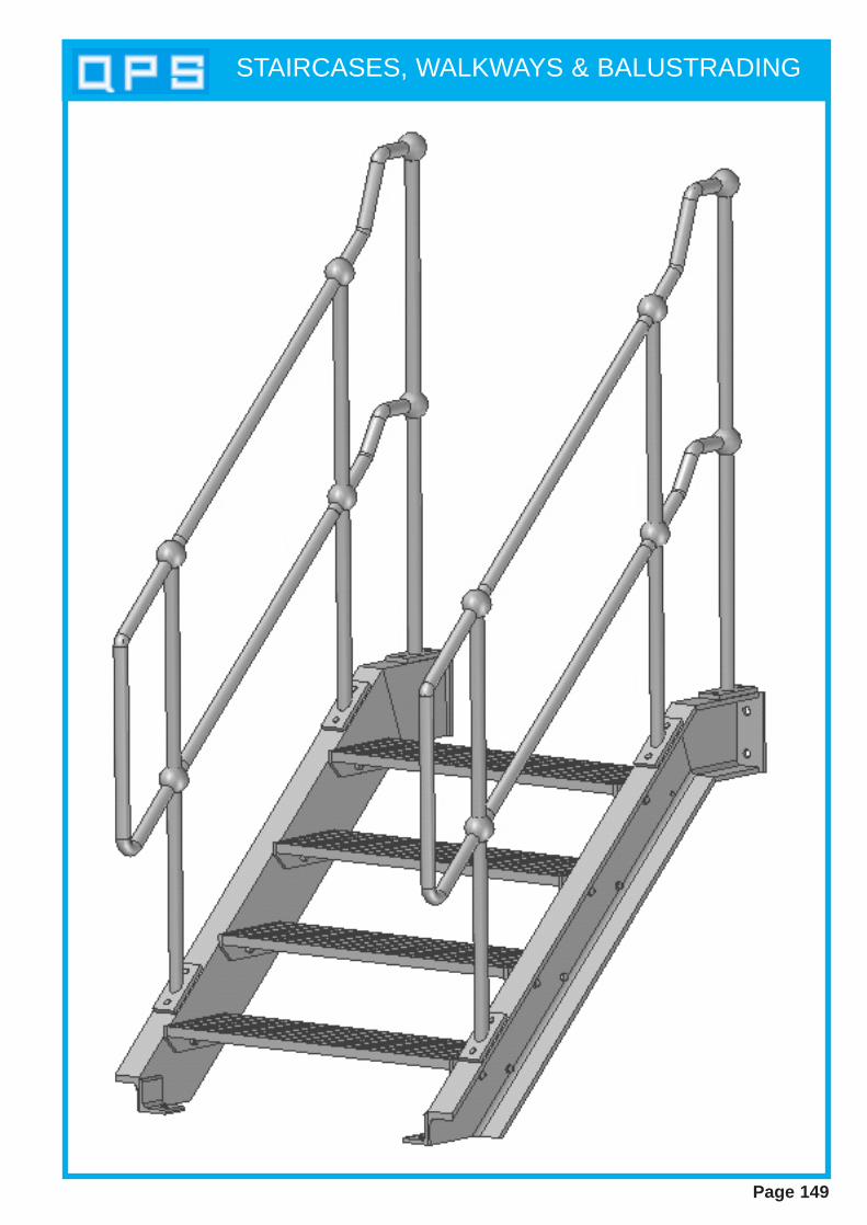
STAIRCASES, WALKWAYS & BALUSTRADING
Page 149
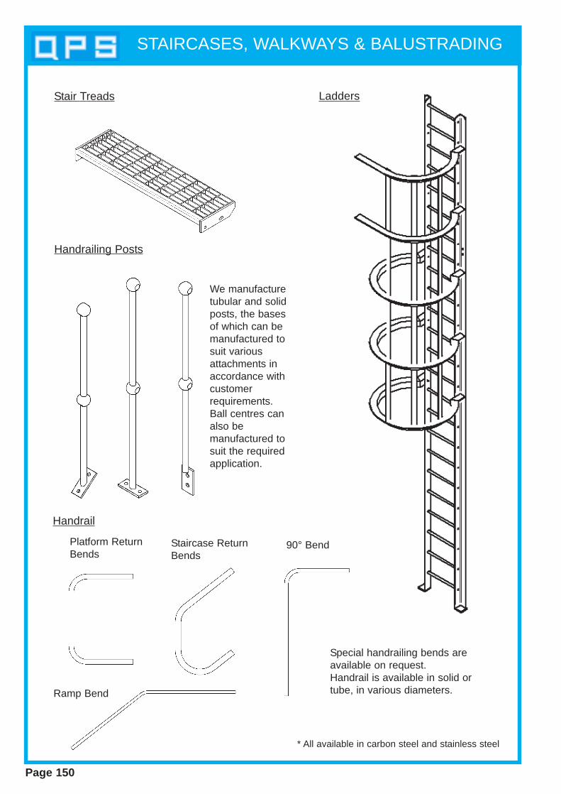
Stair Treads
Handrailing Posts
Platform ReturnBends
90° Bend
Ramp Bend
Special handrailing bends are available on request.Handrail is available in solid ortube, in various diameters.
We manufacturetubular and solidposts, the basesof which can bemanufactured tosuit variousattachments inaccordance withcustomerrequirements.Ball centres canalso be manufactured tosuit the requiredapplication.
Ladders
* All available in carbon steel and stainless steel
Handrail
Staircase ReturnBends
STAIRCASES, WALKWAYS & BALUSTRADING
Page 150

Unistrut
Section 10
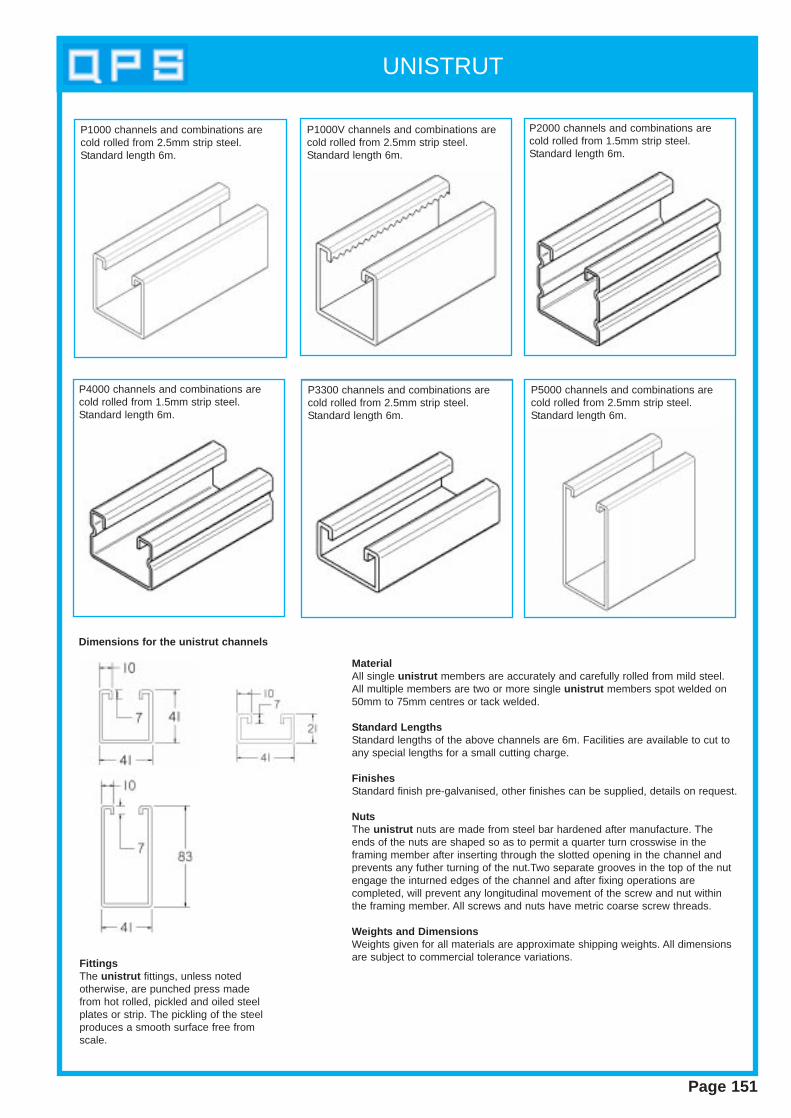
UNISTRUT
Page 151
MaterialAll single unistrut members are accurately and carefully rolled from mild steel.All multiple members are two or more single unistrut members spot welded on50mm to 75mm centres or tack welded.
Standard Lengths Standard lengths of the above channels are 6m. Facilities are available to cut toany special lengths for a small cutting charge.
Finishes Standard finish pre-galvanised, other finishes can be supplied, details on request.
Nuts The unistrut nuts are made from steel bar hardened after manufacture. Theends of the nuts are shaped so as to permit a quarter turn crosswise in the framing member after inserting through the slotted opening in the channel andprevents any futher turning of the nut.Two separate grooves in the top of the nutengage the inturned edges of the channel and after fixing operations are completed, will prevent any longitudinal movement of the screw and nut withinthe framing member. All screws and nuts have metric coarse screw threads.
Weights and DimensionsWeights given for all materials are approximate shipping weights. All dimensionsare subject to commercial tolerance variations.
FittingsThe unistrut fittings, unless noted otherwise, are punched press madefrom hot rolled, pickled and oiled steelplates or strip. The pickling of the steelproduces a smooth surface free fromscale.
P1000 channels and combinations arecold rolled from 2.5mm strip steel.Standard length 6m.
P1000V channels and combinations arecold rolled from 2.5mm strip steel.Standard length 6m.
P2000 channels and combinations arecold rolled from 1.5mm strip steel.Standard length 6m.
P4000 channels and combinations arecold rolled from 1.5mm strip steel.Standard length 6m.
P5000 channels and combinations arecold rolled from 2.5mm strip steel.Standard length 6m.
P3300 channels and combinations arecold rolled from 2.5mm strip steel.Standard length 6m.
Dimensions for the unistrut channels
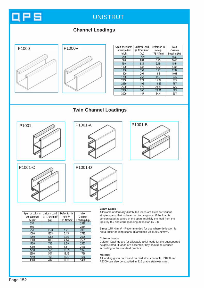
UNISTRUT
Page 152
Span or column Uniform Load Deflection in Maxunsupported @ 175N/mm² mm @ Column
height (kg) 175 N/mm² Loading (kg)250 1769 0.23 1693500 884 0.95 1650750 589 2.15 15541000 442 3.82 13951250 353 5.97 12321500 294 8.6 10931750 252 11.7 9762000 221 15.29 8792250 196 19.35 7972500 176 23.89 7252750 160 28.91 6633000 147 34.4 607
P1000 P1000V
P1001 P1001-A P1001-B
P1001-C P1001-D
Span or column Uniform Load Deflection in Maxunsupported @ 175N/mm² mm @ Column
height (kg) 175 N/mm² Loading (kg)250 2880500 2864750 1670 1.21 28331000 1253 2.15 27831250 1002 3.36 26951500 835 4.84 25511750 716 6.59 23672000 626 8.61 21702250 556 10.89 19772500 501 13.45 17962750 455 16.27 16303000 417 19.37 1480
Beam Loads Allowable uniformally distributed loads are listed for various simple spans, that is, beam on two supports. If the load is concentrated at centre of the span, mulitiply the load from thetable by 0.5 and corresponding deflection by 0.8.
Stress 175 N/mm² - Recommended for use where deflection isnot a factor on long spans, guaranteed yield 280 N/mm².
Column Loads Column loadings are for allowable axial loads for the unsupportedheights listed. If loads are eccentric, they should be reducedaccording to the standard practice.
MaterialAll loading given are based on mild steel channels. P1000 andP3300 can also be supplied in 316 grade stainless steel.
Channel Loadings
Twin Channel Loadings
UNISTRUT
Page 153
P1001-3 P1001-A3 P1001-B3
P1001-C3 P1001-C31 P1001-C32
P1001-C33 P1001-C4 P1001-C41
P1001-C42 P1001-C43 P1001-D3
Channel Combinations
UNISTRUT
Page 154
P2322 P1036 P1031 P1358 P1580
P1026 P1033 P2484 P1326 P1325
P1346 P1458 P1278 P1359 P1727
P2322 P1074 P1186 P1354 P1580
P1043 P1047 P4045 P1737 P1453
Channel Connection Att achment s
UNISTRUT
Page 155
P1045 P4047 P2072-S1 P2072-S2 P2072-S3
P2073 P2073A P2072A P2348-S1 P2348-S2
P2346 P2341 R P2341 L P2223
Channel Connection Att achment s
P2666
P2666 A End Cap P1184 SN PNP 16
PNP PNL PNS
Page 156
NOTES
Lindapters
Section 1 1
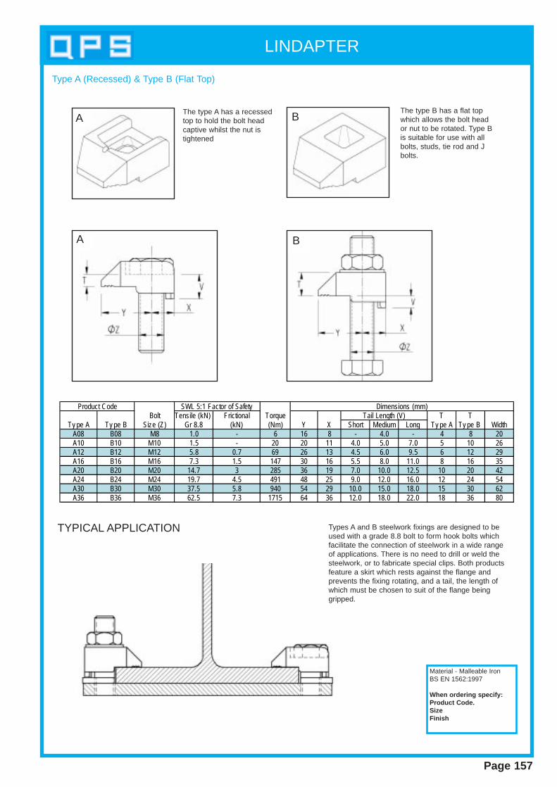
LINDAPTER
Page 157
Type A (Recessed) & Type B (Flat Top)
Bolt Tensile (kN) Frictional Torque T TTy pe A Ty pe B Size (Z) Gr 8.8 (kN) (Nm) Y X Short Medium Long Ty pe A Ty pe B Width
A08 B08 M8 1.0 - 6 16 8 - 4.0 - 4 8 20A10 B10 M10 1.5 - 20 20 11 4.0 5.0 7.0 5 10 26A12 B12 M12 5.8 0.7 69 26 13 4.5 6.0 9.5 6 12 29A16 B16 M16 7.3 1.5 147 30 16 5.5 8.0 11.0 8 16 35A20 B20 M20 14.7 3 285 36 19 7.0 10.0 12.5 10 20 42A24 B24 M24 19.7 4.5 491 48 25 9.0 12.0 16.0 12 24 54A30 B30 M30 37.5 5.8 940 54 29 10.0 15.0 18.0 15 30 62A36 B36 M36 62.5 7.3 1715 64 36 12.0 18.0 22.0 18 36 80
Product Code SWL 5:1 Factor of Safety Dimensions (mm)Tail Length (V)
The type A has a recessedtop to hold the bolt headcaptive whilst the nut istightened
The type B has a flat topwhich allows the bolt heador nut to be rotated. Type Bis suitable for use with allbolts, studs, tie rod and Jbolts.
Material - Malleable IronBS EN 1562:1997
When ordering specify:Product Code.SizeFinish
TYPICAL APPLICATION
A B
A B
Types A and B steelwork fixings are designed to beused with a grade 8.8 bolt to form hook bolts whichfacilitate the connection of steelwork in a wide rangeof applications. There is no need to drill or weld thesteelwork, or to fabricate special clips. Both productsfeature a skirt which rests against the flange and prevents the fixing rotating, and a tail, the length ofwhich must be chosen to suit of the flange beinggripped.
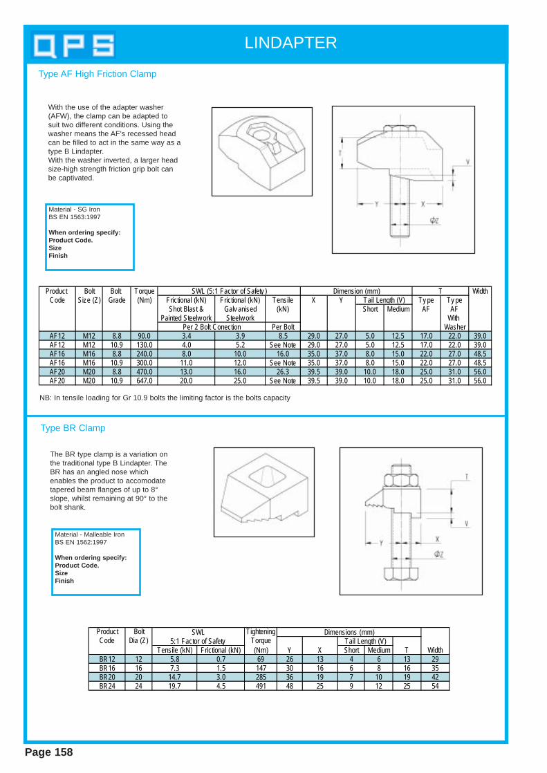
LINDAPTER
Page 158
Type AF High Friction Clamp
Material - SG IronBS EN 1563:1997
When ordering specify:Product Code.SizeFinish
Product Bolt Bolt Torque WidthCode Size (Z) Grade (Nm) Frictional (kN) Frictional (kN) Tensile X Y Ty pe Ty pe
Shot Blast & Galv anised (kN) Short Medium AF AFPainted Steelw ork Steelw ork With
Per Bolt WasherAF12 M12 8.8 90.0 3.4 3.9 8.5 29.0 27.0 5.0 12.5 17.0 22.0 39.0AF12 M12 10.9 130.0 4.0 5.2 See Note 29.0 27.0 5.0 12.5 17.0 22.0 39.0AF16 M16 8.8 240.0 8.0 10.0 16.0 35.0 37.0 8.0 15.0 22.0 27.0 48.5AF16 M16 10.9 300.0 11.0 12.0 See Note 35.0 37.0 8.0 15.0 22.0 27.0 48.5AF20 M20 8.8 470.0 13.0 16.0 26.3 39.5 39.0 10.0 18.0 25.0 31.0 56.0AF20 M20 10.9 647.0 20.0 25.0 See Note 39.5 39.0 10.0 18.0 25.0 31.0 56.0
Per 2 Bolt Conection
Tail Length (V)TDimension (mm)SWL (5:1 Factor of Safety )
NB: In tensile loading for Gr 10.9 bolts the limiting factor is the bolts capacity
With the use of the adapter washer(AFW), the clamp can be adapted tosuit two different conditions. Using thewasher means the AF’s recessed headcan be filled to act in the same way as atype B Lindapter.With the washer inverted, a larger headsize-high strength friction grip bolt canbe captivated.
Type BR Clamp
Material - Malleable IronBS EN 1562:1997
When ordering specify:Product Code.SizeFinish
Product Bolt TighteningCode Dia (Z) Torque
Tensile (kN) Frictional (kN) (Nm) Y X Short Medium T WidthBR12 12 5.8 0.7 69 26 13 4 6 13 29BR16 16 7.3 1.5 147 30 16 6 8 16 35BR20 20 14.7 3.0 285 36 19 7 10 19 42BR24 24 19.7 4.5 491 48 25 9 12 25 54
SWL5:1 Factor of Safety Tail Length (V)
Dimensions (mm)
The BR type clamp is a variation onthe traditional type B Lindapter. TheBR has an angled nose whichenables the product to accomodatetapered beam flanges of up to 8°slope, whilst remaining at 90° to thebolt shank.
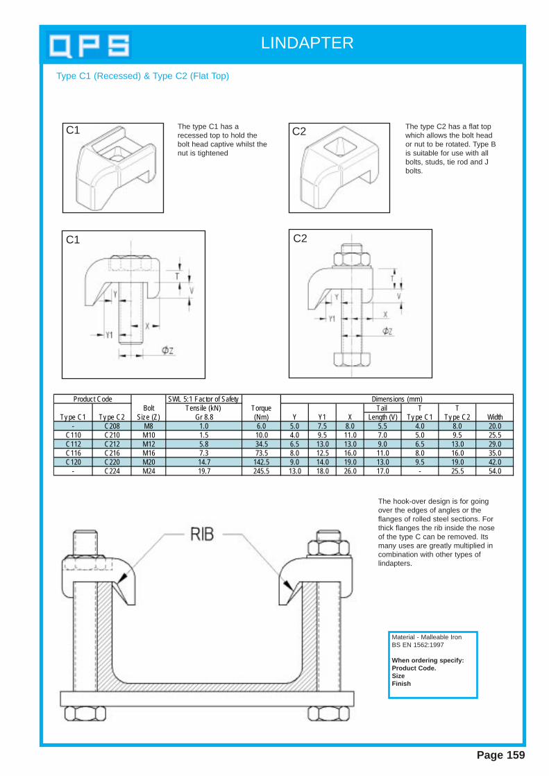
LINDAPTER
Page 159
Type C1 (Recessed) & Type C2 (Flat Top)
The type C1 has arecessed top to hold thebolt head captive whilst thenut is tightened
The type C2 has a flat topwhich allows the bolt heador nut to be rotated. Type Bis suitable for use with allbolts, studs, tie rod and Jbolts.
SWL 5:1 Factor of SafetyBolt Tensile (kN) Torque Tail T T
Ty pe C1 Ty pe C2 Size (Z) Gr 8.8 (Nm) Y Y1 X Length (V) Ty pe C1 Ty pe C2 Width- C208 M8 1.0 6.0 5.0 7.5 8.0 5.5 4.0 8.0 20.0
C110 C210 M10 1.5 10.0 4.0 9.5 11.0 7.0 5.0 9.5 25.5C112 C212 M12 5.8 34.5 6.5 13.0 13.0 9.0 6.5 13.0 29.0C116 C216 M16 7.3 73.5 8.0 12.5 16.0 11.0 8.0 16.0 35.0C120 C220 M20 14.7 142.5 9.0 14.0 19.0 13.0 9.5 19.0 42.0
- C224 M24 19.7 245.5 13.0 18.0 26.0 17.0 - 25.5 54.0
Product Code Dimensions (mm)
Material - Malleable IronBS EN 1562:1997
When ordering specify:Product Code.SizeFinish
C1 C2
C1 C2
The hook-over design is for goingover the edges of angles or theflanges of rolled steel sections. Forthick flanges the rib inside the noseof the type C can be removed. Itsmany uses are greatly multiplied incombination with other types of lindapters.
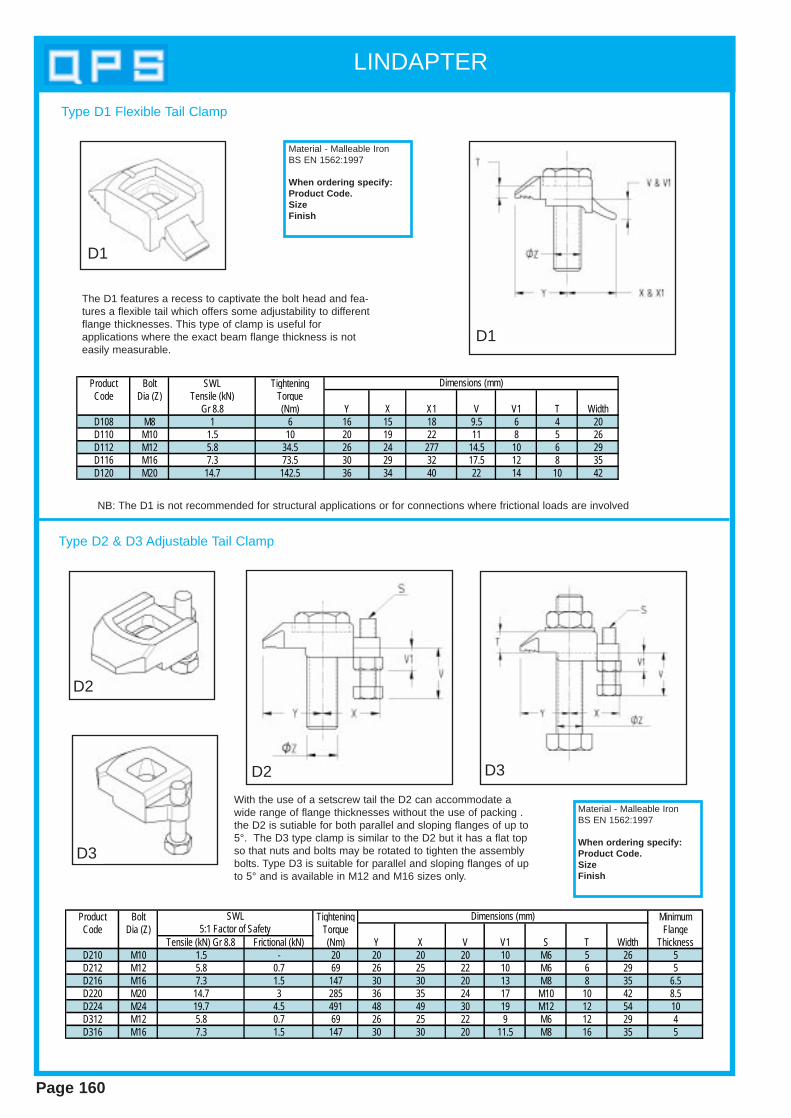
LINDAPTER
Page 160
Material - Malleable IronBS EN 1562:1997
When ordering specify:Product Code.SizeFinish
Type D1 Flexible Tail Clamp
Product Bolt SWL TighteningCode Dia (Z) Tensile (kN) Torque
Gr 8.8 (Nm) Y X X1 V V1 T WidthD108 M8 1 6 16 15 18 9.5 6 4 20D110 M10 1.5 10 20 19 22 11 8 5 26D112 M12 5.8 34.5 26 24 277 14.5 10 6 29D116 M16 7.3 73.5 30 29 32 17.5 12 8 35D120 M20 14.7 142.5 36 34 40 22 14 10 42
Dimensions (mm)
The D1 features a recess to captivate the bolt head and fea-tures a flexible tail which offers some adjustability to differentflange thicknesses. This type of clamp is useful for applications where the exact beam flange thickness is noteasily measurable.
NB: The D1 is not recommended for structural applications or for connections where frictional loads are involved
Type D2 & D3 Adjustable Tail Clamp
Product Bolt Tightening MinimumCode Dia (Z) Torque Flange
Tensile (kN) Gr 8.8 Frictional (kN) (Nm) Y X V V1 S T Width ThicknessD210 M10 1.5 - 20 20 20 20 10 M6 5 26 5D212 M12 5.8 0.7 69 26 25 22 10 M6 6 29 5D216 M16 7.3 1.5 147 30 30 20 13 M8 8 35 6.5D220 M20 14.7 3 285 36 35 24 17 M10 10 42 8.5D224 M24 19.7 4.5 491 48 49 30 19 M12 12 54 10D312 M12 5.8 0.7 69 26 25 22 9 M6 12 29 4D316 M16 7.3 1.5 147 30 30 20 11.5 M8 16 35 5
SWL5:1 Factor of Safety
Dimensions (mm)
Material - Malleable IronBS EN 1562:1997
When ordering specify:Product Code.SizeFinish
D2
D3
With the use of a setscrew tail the D2 can accommodate awide range of flange thicknesses without the use of packing .the D2 is sutiable for both parallel and sloping flanges of up to5°. The D3 type clamp is similar to the D2 but it has a flat topso that nuts and bolts may be rotated to tighten the assemblybolts. Type D3 is suitable for parallel and sloping flanges of upto 5° and is available in M12 and M16 sizes only.
D2 D3
D1
D1
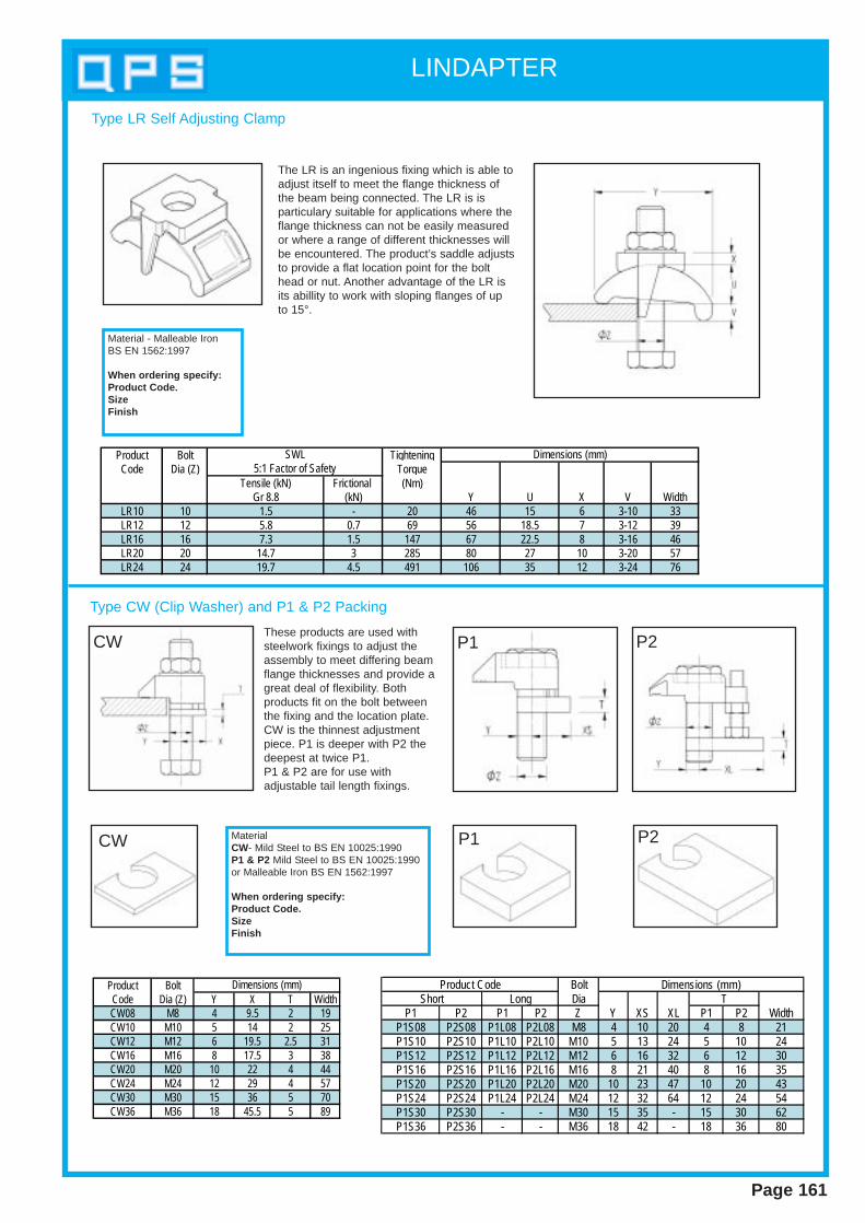
LINDAPTER
Page 161
Type LR Self Adjusting Clamp
Material - Malleable IronBS EN 1562:1997
When ordering specify:Product Code.SizeFinish
The LR is an ingenious fixing which is able toadjust itself to meet the flange thickness ofthe beam being connected. The LR is is particulary suitable for applications where theflange thickness can not be easily measuredor where a range of different thicknesses willbe encountered. The product’s saddle adjuststo provide a flat location point for the bolthead or nut. Another advantage of the LR isits abillity to work with sloping flanges of upto 15°.
Product Bolt TighteningCode Dia (Z) Torque
Tensile (kN) Frictional (Nm)Gr 8.8 (kN) Y U X V Width
LR10 10 1.5 - 20 46 15 6 3-10 33LR12 12 5.8 0.7 69 56 18.5 7 3-12 39LR16 16 7.3 1.5 147 67 22.5 8 3-16 46LR20 20 14.7 3 285 80 27 10 3-20 57LR24 24 19.7 4.5 491 106 35 12 3-24 76
SWL Dimensions (mm)5:1 Factor of Safety
Type CW (Clip Washer) and P1 & P2 Packing
CW Material CW- Mild Steel to BS EN 10025:1990P1 & P2 Mild Steel to BS EN 10025:1990or Malleable Iron BS EN 1562:1997
When ordering specify:Product Code.SizeFinish
Product BoltCode Dia (Z) Y X T WidthCW08 M8 4 9.5 2 19CW10 M10 5 14 2 25CW12 M12 6 19.5 2.5 31CW16 M16 8 17.5 3 38CW20 M20 10 22 4 44CW24 M24 12 29 4 57CW30 M30 15 36 5 70CW36 M36 18 45.5 5 89
Dimensions (mm) BoltDia
P1 P2 P1 P2 Z Y XS XL P1 P2 WidthP1S08 P2S08 P1L08 P2L08 M8 4 10 20 4 8 21P1S10 P2S10 P1L10 P2L10 M10 5 13 24 5 10 24P1S12 P2S12 P1L12 P2L12 M12 6 16 32 6 12 30P1S16 P2S16 P1L16 P2L16 M16 8 21 40 8 16 35P1S20 P2S20 P1L20 P2L20 M20 10 23 47 10 20 43P1S24 P2S24 P1L24 P2L24 M24 12 32 64 12 24 54P1S30 P2S30 - - M30 15 35 - 15 30 62P1S36 P2S36 - - M36 18 42 - 18 36 80
TShort LongProduct Code Dimensions (mm)
P1 P2CW
P1 P2
These products are used withsteelwork fixings to adjust theassembly to meet differing beamflange thicknesses and provide agreat deal of flexibility. Both products fit on the bolt betweenthe fixing and the location plate.CW is the thinnest adjustmentpiece. P1 is deeper with P2 thedeepest at twice P1. P1 & P2 are for use withadjustable tail length fixings.

Page 162
NOTES