introduction embedded system architecture · – broader system-level integration to support...
TRANSCRIPT

1
Nicola Bombieri Franco Fummi Graziano Pravadelli
Dipartimento di Informatica – Università di Verona
�������������� �������������������
22/05/2006 SFM'06-HW 2
Outline
• HDL and Embedded Systems Design• SystemC and VHDL• Platform Based Design• Transaction Level Modeling• Verification by Simulation• Example: a real case• Summary
22/05/2006 SFM'06-HW 3
Introduction
• Electronic systems consist of:– HW platform– SW application layers– Interfaces– Analog components– Sensors and transducers
• Main trends: – Migration from analog to digital processing– Broader system-level integration to support System-
On-a-Chip (SOC) approach
22/05/2006 SFM'06-HW 4
Embedded system architecture
ENVIRONMENT
MEMORY ISP
HARDWIRED UNITApplication-specific logic
TimersA/D and D/A Converters
SEN
SOR
S
AC
TU
AT
OR
S
EMBEDDED SYSTEM
Challenges in the design of embedded systems
• Increasing application complexity even in standard and large volume products– large systems with legacy functions– mixture of event driven and data flow tasks – flexiblity requirements – examples: multimedia, automotive, mobile communication
• Increasing target system complexity– mixture of different technologies, processor types, and design
styles– large systems-on-a-chip combining components from different
sources (IP market)• Numerous constraints and design objectives• Reduced and overlapping design cycles
Hardware/software co-design• Hardware/software co-design:
– combined design of hardware and software • Goals
– design process optimization • Increased design productivity
– design optimization• Improved product quality
• Tasks– co-specification and co-modeling– co-verification– co-design process integration and optimization– design optimization and co-synthesis
HW SW HW SW
co-design classic design
2
22/05/2006 SFM'06-HW 7
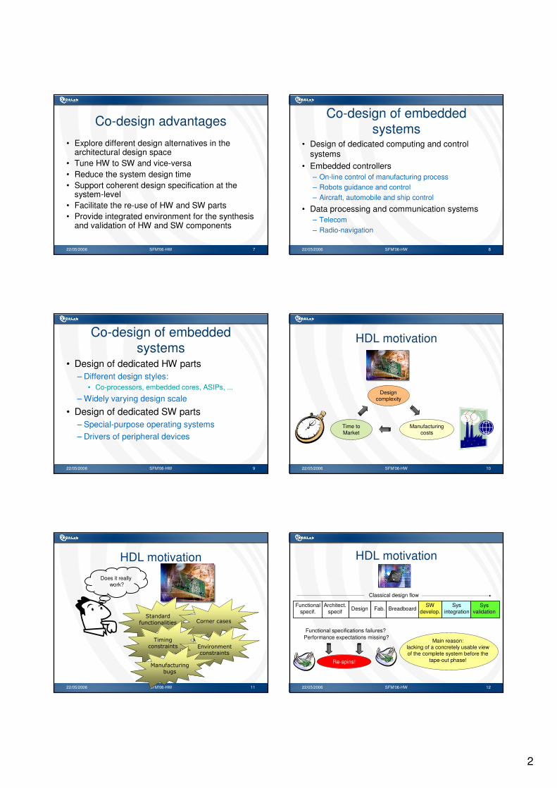
Co-design advantages
• Explore different design alternatives in the architectural design space
• Tune HW to SW and vice-versa• Reduce the system design time• Support coherent design specification at the
system-level• Facilitate the re-use of HW and SW parts• Provide integrated environment for the synthesis
and validation of HW and SW components
22/05/2006 SFM'06-HW 8
Co-design of embedded systems
• Design of dedicated computing and control systems
• Embedded controllers– On-line control of manufacturing process– Robots guidance and control– Aircraft, automobile and ship control
• Data processing and communication systems– Telecom– Radio-navigation
22/05/2006 SFM'06-HW 9
Co-design of embedded systems
• Design of dedicated HW parts– Different design styles:
• Co-processors, embedded cores, ASIPs, ...
– Widely varying design scale
• Design of dedicated SW parts– Special-purpose operating systems– Drivers of peripheral devices
22/05/2006 SFM'06-HW 10
HDL motivation
Manufacturing costs
Design complexity
Time toMarket
22/05/2006 SFM'06-HW 11
HDL motivation
Does it reallywork?
����������������� � ���� ���� �
������������� ������� ��
���������
���������������
22/05/2006 SFM'06-HW 12
HDL motivation
Functional specifications failures?Performance expectations missing?
Re-spins!
Main reason:lacking of a concretely usable view of the complete system before the
tape-out phase!
Functionalspecif.
Architect.specif Design Fab. Breadboard
SWdevelop.
Sysintegration
Sysvalidation
Classical design flow
3
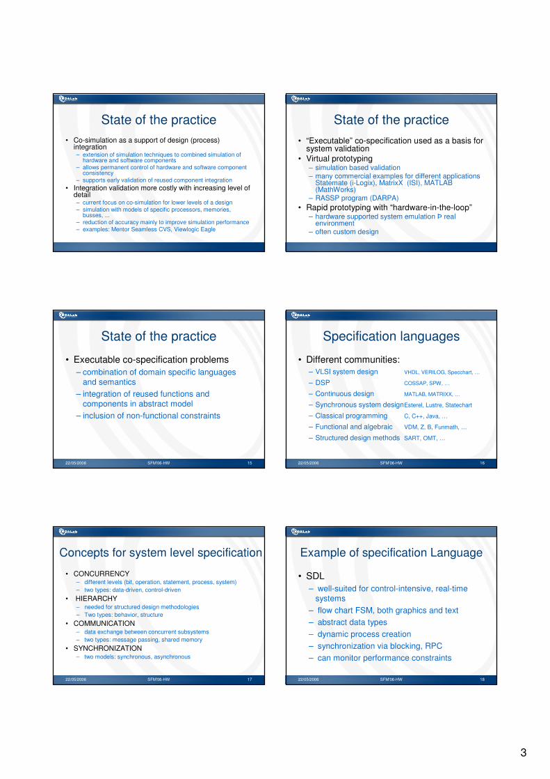
State of the practice• Co-simulation as a support of design (process)
integration– extension of simulation techniques to combined simulation of
hardware and software components– allows permanent control of hardware and software component
consistency– supports early validation of reused component integration
• Integration validation more costly with increasing level of detail– current focus on co-simulation for lower levels of a design– simulation with models of specific processors, memories,
busses, ... – reduction of accuracy mainly to improve simulation performance– examples: Mentor Seamless CVS, Viewlogic Eagle
State of the practice• “Executable” co-specification used as a basis for
system validation• Virtual prototyping
– simulation based validation– many commercial examples for different applications
Statemate (i-Logix), MatrixX (ISI), MATLAB (MathWorks)
– RASSP program (DARPA)• Rapid prototyping with “hardware-in-the-loop”
– hardware supported system emulation Þ real environment
– often custom design
22/05/2006 SFM'06-HW 15
State of the practice
• Executable co-specification problems– combination of domain specific languages
and semantics– integration of reused functions and
components in abstract model– inclusion of non-functional constraints
22/05/2006 SFM'06-HW 16
Specification languages
• Different communities:– VLSI system design VHDL, VERILOG, Specchart, …
– DSP COSSAP, SPW, …
– Continuous design MATLAB, MATRIXX, …
– Synchronous system designEsterel, Lustre, Statechart
– Classical programming C, C++, Java, …
– Functional and algebraic VDM, Z, B, Funmath, …
– Structured design methods SART, OMT, …
22/05/2006 SFM'06-HW 17
Concepts for system level specification
• CONCURRENCY– different levels (bit, operation, statement, process, system)– two types: data-driven, control-driven
• HIERARCHY– needed for structured design methodologies– Two types: behavior, structure
• COMMUNICATION– data exchange between concurrent subsystems– two types: message passing, shared memory
• SYNCHRONIZATION– two models: synchronous, asynchronous
22/05/2006 SFM'06-HW 18
Example of specification Language
• SDL– well-suited for control-intensive, real-time
systems– flow chart FSM, both graphics and text – abstract data types– dynamic process creation– synchronization via blocking, RPC– can monitor performance constraints

4
22/05/2006 SFM'06-HW 19
Example of specification Language
• StateCharts, SpecCharts– graphical FSM of states and transitions– addition of hierarchical states for modeling complex
reactive behaviors – SpecCharts adds
• behavioral completion• exceptions
– may attach VHDL code to states and transitions arcs– extended with arithmetics– Easy to use for control-dominated systems
22/05/2006 SFM'06-HW 20
Simulation and debugging requirements
• Embedded controllers:– ASICs plus SW running on a processor– VHDL or Verilog plus C programs– Weakly heterogeneous systems
• Embedded data processing and communication systems– ASICs plus SW running on a processor or ASIP– Environmental modeling (e.g. telephone lines)– Strongly heterogeneous systems
22/05/2006 SFM'06-HW 21
Co-simulation
• Simulate at the same time both hardware and software
• Two conflicting requirements:– execute the software as fast as possible– keep hardware and software simulations
synchronized so they interact as they will in the target system.
22/05/2006 SFM'06-HW 22
Co-simulation
• Desired features:– Level of timing accuracy– Speed of simulation runs– Visibility of internal states
• Potential problems:– Meaningful results are obtained with large SW
programs– Model availability– Strong heterogeneity requires specialized
environment
22/05/2006 SFM'06-HW 23
Co-simulation paradigms
• Homogeneous modeling:– HW models in HDL
– Processor model in HDL
– SW in assembly code
• Usage of HDL simulator for the whole system
including the processor model
• Simple method but quite inefficient
22/05/2006 SFM'06-HW 24
Co-simulation paradigms
• Weakly heterogeneous systems– a) HDL simulators with processor model– b) Compiled SW– c) HW emulation
• Strongly heterogeneous systems– Require specialized simulation environments
(e.g. Ptolemy)– Communication mechanisms among domains
and their corresponding schedulers

5
22/05/2006 SFM'06-HW 25
HDL processor modeling
• Precise timing model– Accurate timing and complete functionality
• Event-driven simulation
• Zero-Delay Model (ZDM) for timing– Correct transitions at clock edges
• Cycle-based simulation
• Instruction-set simulator – Model emulates processor while insuring
correct register and memory values
22/05/2006 SFM'06-HW 26
Compiled SW
• Basic assumption:– HW/SW communication protocol such that
communication delay has no effect on functionality
• SW is compiled and linked to simulator• HW/SW communication is replaced by
handshake• Simulation speed is limited by HW
simulation speed
22/05/2006 SFM'06-HW 27
HW emulation
• HW mapped onto programmable HW
– One order of magnitude loss in speed
• Programmable HW boards connected to
workstations
• Limited visibility of internal states
22/05/2006 SFM'06-HW 28
Software versus Hardware DesignSoftware versus Hardware Design
AlgorithmAlgorithm
TT
MBMB
ArchitectureArchitecture
MHzMHz
GateGate
AlgorithmAlgorithm
PrePre--defined defined Virtual MachineVirtual Machine
22/05/2006 SFM'06-HW 29
Example: GCD modeled in CExample: GCD modeled in C#include <stdio.h>
int gcd(int xi, int yi){
int x, y, temp;
x = xi;y = yi;while (x > 0){
if (x <= y){temp = y;y = x;x = temp;
}x = x - y;
}return(y);
}
main(){
int xi, yi, ou;
scanf("%d %d", &xi, &yi);ou = gcd(xi, yi);printf("%d\n", ou);
}
22/05/2006 SFM'06-HW 30
Hardware requirements (1)
• Input /OutputS printf, scanf...
Hcomponent interface must be defined
• TimingSCPU instructions are executed at the CPU
clock speedHone or more explicit CLOCK signals must be
defined

6
22/05/2006 SFM'06-HW 31
Hardware requirements (2)
• Variables sizeShidden implicit definition (integer 4bytes, char
1byte, …)Hall pre-defined and user-defined types must
be translated into bit vectors
• Relationships operands/operatorsSall operators in the C libraries are acceptedHexplicit mapping of operands on operators
22/05/2006 SFM'06-HW 32
Hardware requirements (3)
• Memory elements identificationSthe optimization module of the compiler
transparently maps variables onto CPU registers and memory elements
Hthe synthesis tool identifies memory elements by analyzing the algorithmic semantics
• Modules synchronizationSsequential execution of instructionsHinherently parallel execution of all
components
22/05/2006 SFM'06-HW 33
Entity/ArchitectureEntity/Architecture
GCDGCDYIYIXIXI
OUOU
CLOCKCLOCK RESETRESET
ENTITY gcd ISPORT ( clock, reset : IN bit;
xi,yi : IN unsigned (size-1 DOWNTO 0);ou : OUT unsigned (size-1 DOWNTO 0)
);END gcd;
variable sizevariable size22/05/2006 SFM'06-HW 34
Example: GCD modeled in VHDLExample: GCD modeled in VHDLARCHITECTURE behavioral OF gcd ISBEGIN
PROCESSVARIABLE x, y,temp : unsigned (size-1 DOWNTO 0);
BEGINWAIT UNTIL clock = '1';x := xi;y := yi;WHILE (x > 0) LOOP
IF (x <= y) THENtemp:=y;y := x;x:=temp;
END IF;x := x - y;
END LOOP;ou <= y;END PROCESS;
END behavioral;
timingtiming
memoriesmemories
22/05/2006 SFM'06-HW 35
• Identification of a target architecture– FSM + Data-Path (FSMD)
• Identification of time instants for each operation:– time order– time length
• Identification of operators:– data size– time performance
Algorithmic (Behavioral) Synthesis
schedulingscheduling
allocationallocation
22/05/2006 SFM'06-HW 36
FSMD ModelFSMD ModelPRIMARY INPUTS
CLOCK
CONTROLUNIT(FSM)
ELABORATIONUNIT
(Data-path)
RESET
PRIMARY OUTPUTS
CONTROL SIGNALS
CONDITION SIGNALS
FSMD
7
22/05/2006 SFM'06-HW 37
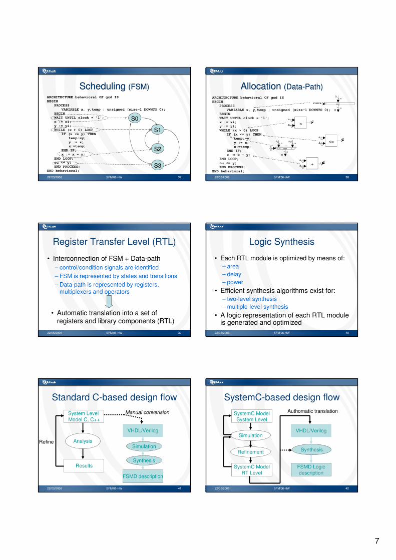
Scheduling (FSM)Scheduling (FSM)ARCHITECTURE behavioral OF gcd ISBEGIN
PROCESSVARIABLE x, y,temp : unsigned (size-1 DOWNTO 0);
BEGINWAIT UNTIL clock = '1';x := xi;y := yi;WHILE (x > 0) LOOP
IF (x <= y) THENtemp:=y;y := x;x:=temp;
END IF;x := x - y;
END LOOP;ou <= y;END PROCESS;
END behavioral;
S0S0
S1S1
S2S2
S3S3
22/05/2006 SFM'06-HW 38
Allocation (Data-Path)Allocation (Data-Path)ARCHITECTURE behavioral OF gcd ISBEGIN
PROCESSVARIABLE x, y,temp : unsigned (size-1 DOWNTO 0);
BEGINWAIT UNTIL clock = '1';x := xi;y := yi;WHILE (x > 0) LOOP
IF (x <= y) THENtemp:=y;y := x;x:=temp;
END IF;x := x - y;
END LOOP;ou <= y;END PROCESS;
END behavioral;
A
B
On
n>
A
B
On
n<=
S
n n
nO
muxm
A1 2mA
. . .0...0 1...1
A
B nOn
n+
CLOCK
nD
nQ
reg
22/05/2006 SFM'06-HW 39
Register Transfer Level (RTL)
• Interconnection of FSM + Data-path– control/condition signals are identified– FSM is represented by states and transitions– Data-path is represented by registers,
multiplexers and operators
• Automatic translation into a set of registers and library components (RTL)
22/05/2006 SFM'06-HW 40
Logic Synthesis
• Each RTL module is optimized by means of:– area– delay– power
• Efficient synthesis algorithms exist for:– two-level synthesis– multiple-level synthesis
• A logic representation of each RTL module is generated and optimized
22/05/2006 SFM'06-HW 41
Standard C-based design flow
Refine
System LevelModel C, C++
Results
Analysis
Manual converision
VHDL/Verilog
Simulation
Synthesis
FSMD description
22/05/2006 SFM'06-HW 42
SystemC-based design flow
VHDL/Verilog
Synthesis
FSMD Logicdescription
SystemC ModelSystem Level
SystemC ModelRT Level
Refinement
Simulation
Authomatic translation
8
22/05/2006 SFM'06-HW 43
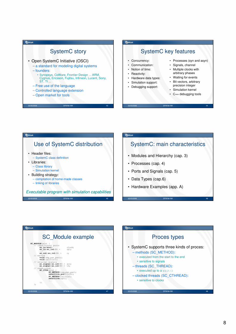
SystemC story
• Open SystemC Initiative (OSCI)– a standard for modeling digital systems– founders:
• Synopsys, CoWare, Frontier Design ... ARM, Cygnus, Ericsson, Fujitsu, Infineon, Lucent, Sony, ST, TI ...
– Free use of the language– Controlled language extension– Open market for tools
22/05/2006 SFM'06-HW 44
SystemC key features• Concurrency:• Communication:• Notion of time:• Reactivity:• Hardware data types:• Simulation support:• Debugging support:
• Processes (syn and asyn)• Signals, channel• Multiple clocks with
arbitrary phases• Waiting for events• Bit vectors, arbitrary
precision integer• Simulation kernel• C++ debugging tools
22/05/2006 SFM'06-HW 45
Use of SystemC distribution
• Header files:– SystemC class definition
• Libraries:– Class library– Simulation kernel
• Building strategy:– compilation of home-made classes– linking of libraries
ExecutableExecutable program program withwith simulationsimulation capabilitiescapabilities22/05/2006 SFM'06-HW 46
SystemC: main characteristics
• Modules and Hierarchy (cap. 3)
• Processes (cap. 4)
• Ports and Signals (cap. 5)
• Data Types (cap.6)
• Hardware Examples (app. A)
22/05/2006 SFM'06-HW 47
SC_Module exampleSC_MODULE(alu) {
// input/output portssc_in<bool> clock;sc_in<sc_int<N> > op1;...sc_out<sc_int<N> > o;
// methodvoid reg_par_par();void calcola();
// internal signalssc_signal<sc_int<N> > acc;sc_signal<sc_int<N> > t6;
// constructorSC_CTOR(alu) {
SC_METHOD(reg_par_par);sensitive_pos(clock);SC_METHOD(calcola);sensitive(op1);...
};};
22/05/2006 SFM'06-HW 48
Proces types
• SystemC supports three kinds of proces:– methods (SC_METHOD):
• executed from the start to the end• sensitive to signals
– threads (SC_THREAD):• executed up to a wait()
– clocked threads (SC_CTHREAD):• sensitive to clocks
9
22/05/2006 SFM'06-HW 49
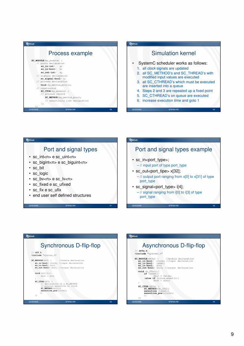
Process exampleSC_MODULE(my_module) {
// ports declarationsc_in<int> a;sc_in<bool> b;
sc_out<int> x;
// signals declarationsc_signal<bool> c;
// process declaration
void my_method_proc();
// constructorSC_CTOR(my_module) {// process record
SC_METHOD(my_method_proc);
// sensitivity list declaration};
};22/05/2006 SFM'06-HW 50
Simulation kernel
• SystemC scheduler works as follows: 1.1. allall clockclock signalssignals are are updatedupdated2.2. allall SC_METHODSC_METHOD’’s and SC_THREADs and SC_THREAD’’s s withwith
modifiedmodified input input valuesvalues are are executedexecuted3.3. allall SC_CTHREADSC_CTHREAD’’s s whichwhich mustmust bebe executedexecuted
are are insertedinserted intointo a a queuequeue4.4. StepsSteps 2 and 3 are 2 and 3 are repeatedrepeated up a up a fixedfixed pointpoint5.5. SC_CTHREADSC_CTHREAD’’s on s on queuequeue are are executedexecuted6.6. increaseincrease executionexecution time and goto 1time and goto 1
22/05/2006 SFM'06-HW 51
Port and signal types• sc_int<n> e sc_uint<n>• sc_bigint<n> e sc_biguint<n>• sc_bit• sc_logic• sc_bv<n> e sc_lv<n>• sc_fixed e sc_ufixed• sc_fix e sc_ufix• end user self defined structures
22/05/2006 SFM'06-HW 52
Port and signal types example
• sc_in<port_type>; – // input port of type port_type
• sc_out<port_tipe> x[32]; – // output port ranging from x[0] to x[31] of type
port_type
• sc_signal<port_type> i[4];– // signal ranging from i[0] to i[3] of type
port_type
22/05/2006 SFM'06-HW 53
Synchronous D-flip-flop// dff.h#include "systemc.h"
SC_MODULE(dff) { //module declaration
sc_in<bool> clock; //input declarationsc_in<bool> din;sc_out<bool> dout; //output declaration
void doit();{
dout = din;
}
SC_CTOR(dff) {// declaration of a SC_METHOD// process sensitive to clockSC_METHOD(doit);sensitive_pos(clock);};
};
22/05/2006 SFM'06-HW 54
Asynchronous D-flip-flop// dffa.h#include "systemc.h"
SC_MODULE(dffa) { //module declarationsc_in<bool> clock; //input declarationsc_in<bool> reset; sc_in<bool> din;sc_out<bool> dout; //output declaration
void do_ffa();{if (reset){
dout = false;}else if (clock.event()){
dout = din;}}
SC_CTOR(dffa) {SC_METHOD(do_ffa);sensitive (reset);sensitive_pos(clock);};
};

10
22/05/2006 SFM'06-HW 55
Parallel-parallel register// reg_par_par.h
#include "systemc.h"#define N 8
SC_MODULE(reg_par_par) { //module declaration
sc_in<bool> clock; //input declarationsc_in<sc_bv<N> > d;sc_out<sc_bv<N> > q; //output declaration
//method to build the registervoid register_par_par();
// constructor declarationSC_CTOR(reg_par_par) {
// declaration of a SC_METHOD// process sensitive to clockSC_METHOD(register_par_par);sensitive_pos(clock);
};};
22/05/2006 SFM'06-HW 56
Parallel-parallel register// reg_par_par.cpp
#include "reg_par_par.h“
// method implementationvoid reg_par_par::register_par_par(){
static sc_bv<N> reg;// local variable
reg = d.read(); // input port readingq.write(reg); // output port writing
}
22/05/2006 SFM'06-HW 57
Serial/serial register// reg_ser_ser.h#include "systemc.h"#define N 8
SC_MODULE(reg_ser_ser) {sc_in<bool> clock; sc_in<bool> i0;sc_out<bool> o;
void register_ser_ser();
SC_CTOR(reg_ser_ser) {SC_METHOD(register_ser_ser);sensitive_pos(clock);
};};
22/05/2006 SFM'06-HW 58
Serial/serial register// reg_ser_ser.cpp#include "reg_ser_ser.h"
void reg_ser_ser::register_ser_ser(){
static sc_bv<N> reg = "00000000";bool i01;
i01 = i0.read();
reg.range(N-2,0) = reg.range(N-1,1);reg[N-1] = i01;
i01 = (reg[0] == ’1’) ? 1 : 0;
o.write(i01); }
22/05/2006 SFM'06-HW 59
Parallel/serial register// reg_par_ser.h#include "systemc.h"#define N 8
SC_MODULE(reg_par_ser) {sc_in<bool> clock; sc_in<bool> i0;sc_in<sc_bv<N> > d; sc_in<bool> ps; sc_out<sc_bv<N> > q; sc_out<bool> o;
void register_par_ser();
SC_CTOR(reg_par_ser) {SC_METHOD(register_par_ser);sensitive_pos(clock);
};};
22/05/2006 SFM'06-HW 60
Parallel/serial register// reg_par_ser.cppvoid reg_par_ser::register_par_ser(){
static sc_bv<N> reg = "00000000bool i01, ps1;
ps1 = ps.read();if (ps1 == 1){
reg =d.read();}else{
i01 = i0.read();reg.range(N-2,0) = reg.range(N-1,1);reg[N-1] = i01;
}i01 = (reg[0] == ’1’) ? 1 : 0;o.write(i01);q.write(reg);
}
11
22/05/2006 SFM'06-HW 61
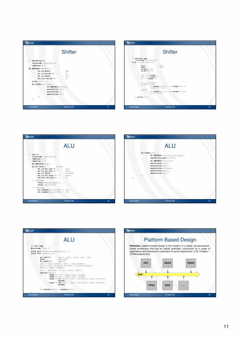
Shifter// shiftrer.h
#include "systemc.h"#define N 8
SC_MODULE(shifter) {sc_in<bool> ds;sc_in<sc_bv<N> > a;sc_in<bool> i0;sc_out<sc_bv<N> > o;
void shift();
SC_CTOR(shifter) {SC_METHOD(shift);sensitive(ds);sensitive(a);sensitive(i0);
};};
22/05/2006 SFM'06-HW 62
Shifter// shifter.cpp
#include "shifter.h"void shifter::shift()
{bool ds1;bool i01;sc_bv<N> a1;sc_bv<N> c1;
i01 = i0.read();ds1 = ds.read();a1 = a.read();
// rigth shiftif(ds1 == 1){
c1.range(N-2,0) = a1.range(N-1,1);c1[N-1] = i01;
}else{c1.range(N-1,1) = a1.range(N-2,0);c1[0] = i01;
}o.write(c1); }
22/05/2006 SFM'06-HW 63
ALU// alu.h
#include "systemc.h"#define N 8#define P 2
SC_MODULE(alu) {sc_in<bool> clock;
sc_in<sc_int<N> > op1;sc_in<sc_int<N> > op2;sc_in<bool> stored;sc_in<sc_uint<P> > oper;sc_out<sc_int<N> > o;
// methodsvoid reg_par_par();void calcola();
// signalssc_signal<sc_int<N> > acc;sc_signal<sc_int<N> > t6;
22/05/2006 SFM'06-HW 64
ALUSC_CTOR(alu) {
SC_METHOD(registro_par_par);sensitive_pos(clock);
SC_METHOD(calcola);sensitive(op1);sensitive(op2);sensitive(stored);sensitive(oper);sensitive(acc);
};};
22/05/2006 SFM'06-HW 65
ALU// alu.cpp#include "alu.h"
void alu::register_par_par(){..}void alu::calcola(){
sc_int<N> op11, op21, acc1, sel, t61;bool stored1;sc_uint<P> oper1;op11 = op1.read(); op21 = op2.read();acc1 = acc.read(); stored1 = stored.read();oper1 = oper.read()
sel = (stored1 == 1) ? acc1; op21;switch(opr1){
case 0: t61 = op11+sel; break;case 1: t61 = op11-sel; break;case 2: if(op11 < sel) t61=op11; else t61=sel;
break;case 3: if(op11 > sel) t61=op11; else t61=sel;
break;}
t6.write(t61); o.write(t61);
}22/05/2006 SFM'06-HW 66
Platform Based Design
���
�������
���� ����
����
�
Definition: platform-based design is the creation of a stable microprocessor-based architecture that can be rapidly extended, customized for a range of applications and delivered to customers for quick deployment. (J.M. Chateau –STMicroelectronics)
12
22/05/2006 SFM'06-HW 67
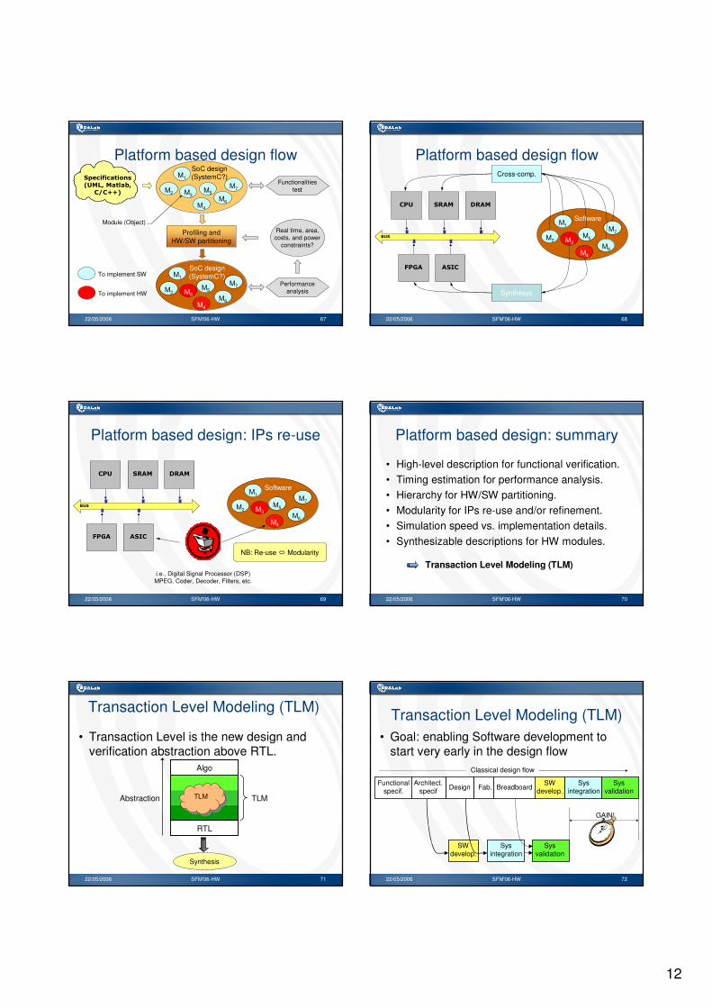
Platform based design flow��� ! ����
"�� #������$#�
�%�&&'
Functionalitiestest
Profiling andHW/SW partitioning
M1
M2 M3
M4
M5M6
M7
SoC design(SystemC?)
M1
M2 M3
M4
M5
M6
M7
SoC design(SystemC?)
Performanceanalysis
Real time, area,costs, and power
constraints?
Module (Object)
To implement SW
To implement HW
22/05/2006 SFM'06-HW 68
Platform based design flow
���
�������
���� ����
����
M1
M2 M3M5
M7
Software
M4
M6
Cross-comp.
Synthesys
22/05/2006 SFM'06-HW 69
Platform based design: IPs re-use
���
�������
���� ����
����
M1
M2 M3M5
M7
Software
M4
M6
NB: Re-use � Modularity
i.e., Digital Signal Processor (DSP)MPEG, Coder, Decoder, Filters, etc.
22/05/2006 SFM'06-HW 70
Platform based design: summary
• High-level description for functional verification.• Timing estimation for performance analysis.• Hierarchy for HW/SW partitioning.• Modularity for IPs re-use and/or refinement.• Simulation speed vs. implementation details.• Synthesizable descriptions for HW modules.
Transaction Level Modeling (TLM)
22/05/2006 SFM'06-HW 71
Transaction Level Modeling (TLM)
• Transaction Level is the new design and verification abstraction above RTL.
Algo
TLMAbstraction
RTL
Synthesis
TLMTLM
22/05/2006 SFM'06-HW 72
Transaction Level Modeling (TLM)
Functionalspecif.
Architect.specif Design Fab. Breadboard
SWdevelop.
Sysintegration
Sysvalidation
Classical design flow
SWdevelop.
Sysintegration
Sysvalidation
GAIN!
• Goal: enabling Software development to start very early in the design flow

13
22/05/2006 SFM'06-HW 73
Transaction Level Modeling (TLM)• Key concept: more emphasis on the data transfer functionality and
less on their implementation details at the early design stage.
write (data, addr);
clk
req
gnt
data_0
data_31
addr_0
addr_31
……
RTL TLM
22/05/2006 SFM'06-HW 74
TLM: design languages
Algo
Abstr.
RTL
Synthesis
TLMTLM
�������
������(����
�����
� ����
� �� �
� ����
--
--
--
--
22/05/2006 SFM'06-HW 75
TLM design languages
• SystemC 2.0.1 � IEEE 1666.• Open SystemC Initiative (OSCI) Standard
TLM: released in February 2005, rigorously defines implementation rules:– API defined for every TLM layer, since they
form the heart of the TLM standard.– Transactor: to allow communications between
components implemented at different abstraction levels.
22/05/2006 SFM'06-HW 76
TLM design languages
• Other implementation rules:– Argument passing semantics in function calls, to
assure safety in concurrent environments.– Blocking/non-blocking calls to characterize
communication semantics (i.e. polling, interrupt, etc.).– Pipelined communication mechanism, to implement
different architectural choices to meet throughput requirements.
– Uni/Bidirectional communication channels, to implement FIFO's or hierarchical channels.
22/05/2006 SFM'06-HW 77
TLM layers
!��
�( ��
� �����
�����$�������
�����
) �*� ��+
�� ,�� ����
)���!��-
����������./��
")���%������'
�0����$�(������
) �*�� ,�� ����)���� ���
1
������ ������� ��
")���%������'
��� ! �����������2
"�����#�
����������
3��4����� , �$5
��6+��67
��85��!����!������8��
����7��,�����)� ����� ����
�� ��
9��#
��:���#�(���(
�(��
22/05/2006 SFM'06-HW 78
TLM key concepts
• Factoring out the common elements, the key concepts are:
– To implement a system at higher layer means to implement the system in a more abstract way:
• leave implementation details in order to speed-up simulation (for functional verification purpose).
– To implement a system at lower layer means to add implementation details to the system:
• in order to simulate the system in a more accurate way (for performance analysis purpose and architectural exploration).

14
22/05/2006 SFM'06-HW 79
TLM: architectural exploration
• Sequential re-timing: balancing combinational logic to maximize clock speed.
� ��� � � � ��
������������
���
• Resources sharing: area vs. latency (High-level synthesis).
• Pipeline optimization.
Examples:
22/05/2006 SFM'06-HW 80
TLM layer 3�
� � �
InterfaceModule
Process
� Executable specifications and first level of data and control functional partitioning.
� System proof of concepts.
� Implementation architecture-abstract.
� Untimed functionalities modeling.
� Event-driven simulation semantics.
� Point-to-point Initiator-Target connection.
� Abstract data types.
� Functional verification goal.
� Simulation speed!
22/05/2006 SFM'06-HW 81
TLM layer 2�
� �
BUS
�
Process
Module
Interface
� Hardware architectural performance and detailed behavior analysis.
� HW/SW partitioning and co-development.
� Cycle performance estimation.
� Split pipeline with time delays.
� Mapping ideal architecture into resource-constrained world.
� Memory/Register map accurate.
� Event driven simulation with time estimation.
22/05/2006 SFM'06-HW 82
TLM layer 1�
� �
BUS
�
Process
Module
clk
� Detailed analysis and low level SW development.
� Modeling CA interface for abstract simulation models of IP blocks such as embedded processors.
� Clock-accurate performance simulation
� Clock-accurate protocols mapped to the chosen HW interfaces and bus structures.
� Interface pins are hidden.
� Parametrizable to model different bus protocol and signal interfaces.
� Performance analysis goal
22/05/2006 SFM'06-HW 83
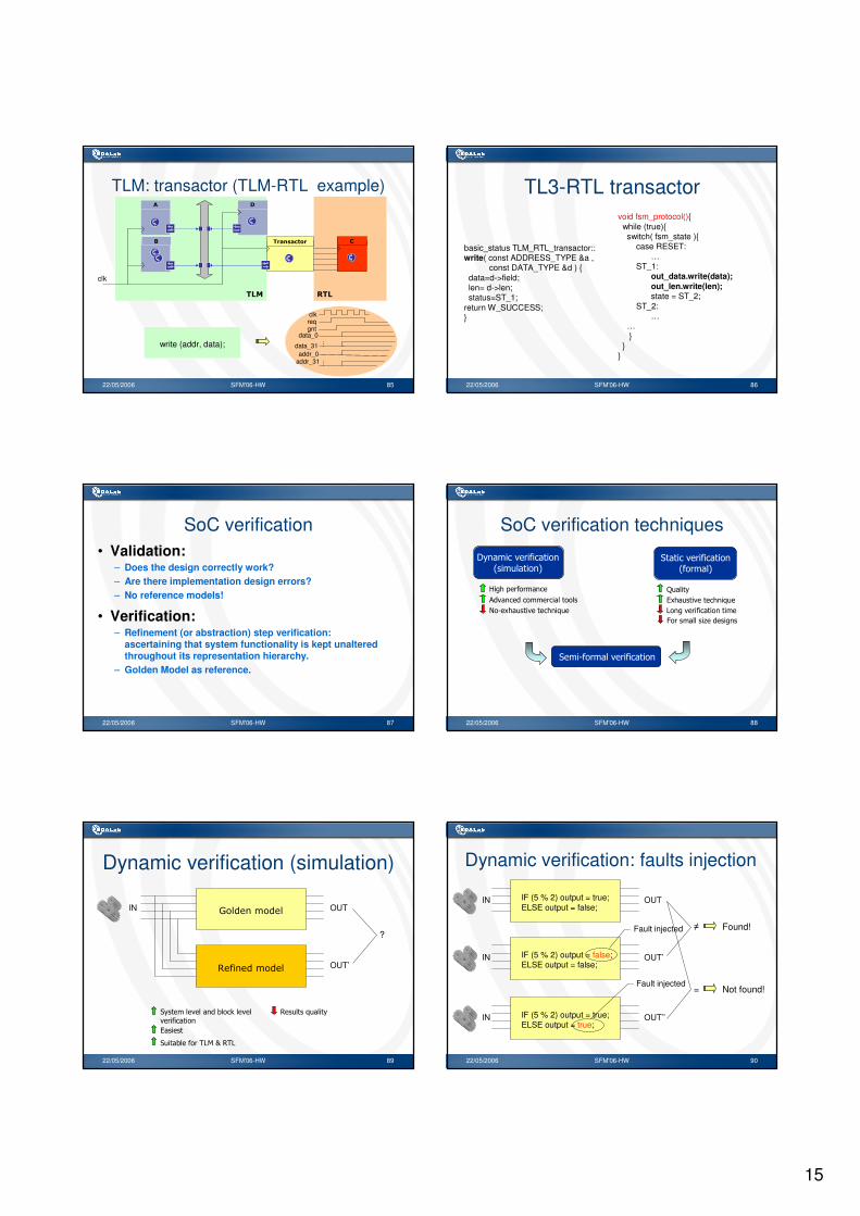
TLM: transactor (TLM-TLM example)
TLM layer iblock
I1 I2 ….. In
O1
… Om
Transactor
O’1 … O’m
I1
status write (Address a, Data d) { . . .
/* Reference block
implemented at
TLM layer i */
return a_status; }
I2 I’1
status write (Address a, Data d) { …
request.a = a;
request.d = d;
request.type = WRITE;
response = transport (request);
return response.status; }
I’2
I’1 I’2 ….. I’n
Resp transport (Request r) { …
/* Blockimplemented atTLM layer i - 1 */
return a_response; }
O1
In
O’1
…
Om
… O’m
…
I’n…
Referenceblock
Refinedblock
TLM layer i-1
block
22/05/2006 SFM'06-HW 84
basic_status mem_slave::write( const ADDRESS_TYPE &a,
const DATA_TYPE &d) {memory[a] = d;return basic_protocol::SUCCESS;
}
basic_status mem_slave::read( const ADDRESS_TYPE &a,
DATA_TYPE &d ) {d = memory[a];return basic_protocol::SUCCESS;
}
master slave
…statusw = port.write(SLAVE_ADDR, 27);…statusr = port.read(SLAVE_ADDR, mem); (thread)
write/read API (i.e.,TL3)
Transactor examples
tlm_transportchannel slavemaster
while(true) {request = in_port->get();switch( request.type ) {
case READ :response.d = memory[request.a];response.status = SUCCESS;break;
case WRITE:…}out_port->put( response );
}
sc_fifo…request.data = &data_pkt;request.address = SLAVE_ADDR;request.type = WRITE;out_port->put(request);
response = in_port->get();…
(thread) (thread)
put/get API (i.e.,TL2)
15
22/05/2006 SFM'06-HW 85
TLM: transactor (TLM-RTL example)�
� )���� ���
�
) �
clk
�
clkreqgnt
data_0
data_31addr_0
addr_31
……
�)
write (addr, data);
22/05/2006 SFM'06-HW 86
basic_status TLM_RTL_transactor::write( const ADDRESS_TYPE &a ,
const DATA_TYPE &d ) {data=d->field;len= d->len;status=ST_1;
return W_SUCCESS;}
void fsm_protocol(){while (true){switch( fsm_state ){
case RESET:…
ST_1:out_data.write(data);out_len.write(len);state = ST_2;
ST_2:…
…}
}}
TL3-RTL transactor
22/05/2006 SFM'06-HW 87
SoC verification• Validation:
– Does the design correctly work?– Are there implementation design errors?– No reference models!
• Verification:– Refinement (or abstraction) step verification:
ascertaining that system functionality is kept unaltered throughout its representation hierarchy.
– Golden Model as reference.
22/05/2006 SFM'06-HW 88
SoC verification techniques
�������������� ���������� ����
��������������
����������������� ����
�������� �� ������
� � ��������� �����������
����� �
����� �� ������
!���������� ���� ��
"�����������#�������
����������������� ���
22/05/2006 SFM'06-HW 89
Dynamic verification (simulation)
$��� ����� �IN OUT
! �� � ��� � OUT’
?
��� ���������$���%���
������ ���
����
&��� ������� �
��� �$������'!(�)�&'!
22/05/2006 SFM'06-HW 90
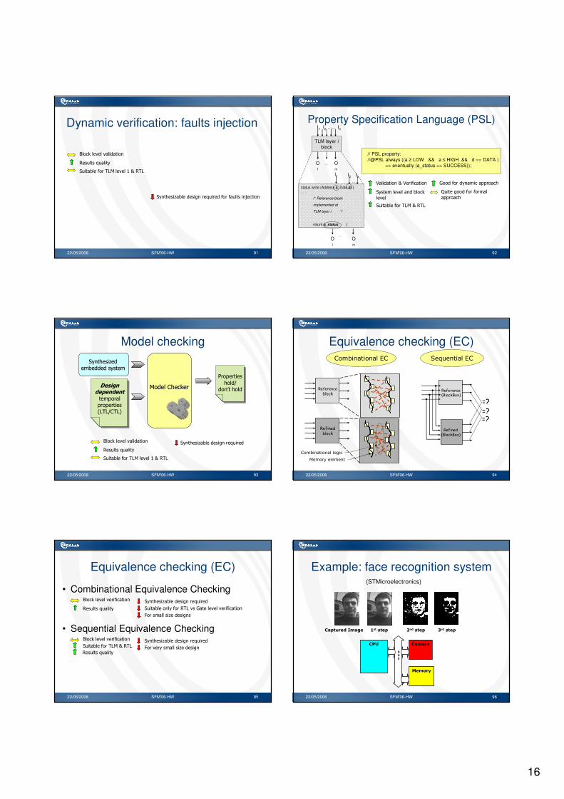
Dynamic verification: faults injection
IF (5 % 2) output = true;ELSE output = false;
IN OUT
IF (5 % 2) output = false;ELSE output = false;
OUT’
Fault injected
IF (5 % 2) output = true;ELSE output = true;
OUT’’
Fault injected
�
=
Found!
Not found!
IN
IN
16
22/05/2006 SFM'06-HW 91
Dynamic verification: faults injection
��� ���#�$����������������������� ����*� ���
+���%��������� ���
&��� ������� �
��� �$������'!(����,�)�&'!
22/05/2006 SFM'06-HW 92
Property Specification Language (PSL)
TLM layer iblock
I1 I2 ….. In
O1
… Om
I1
status write (Address a, Data d) { . . .
/* Reference block
implemented at
TLM layer i */
return a_status; }
I2
O1
In…
Om
…
// PSL property://@PSL always ((a � LOW && a � HIGH && d == DATA )
=> eventually (a_status == SUCCESS));
-����� ����)�-������ ���
��� ���������$���%
��
��� �$������'!(�)�&'!
.������������������������
��� ����������������
��������
22/05/2006 SFM'06-HW 93
Model checking��� ���#���� ���#�
�$������� ��$������� �
�������������� ����������� ���!'!/0'!�
(����0��%�(����0��%�
1���� ������/
���2 �����
+���%��������� ���
&��� ������� �
��� ���#�$��������������
��� �$������'!(����,�)�&'!
22/05/2006 SFM'06-HW 94
Equivalence checking (EC)
���������
���
������� ���
� ��� � � ��
��������� �� ������
��������� ������
��
����
��������������
������������� � %� ������
22/05/2006 SFM'06-HW 95
Equivalence checking (EC)
• Combinational Equivalence Checking+���%���������� ���
&��� ������� �
��� ���#�$��������������
��� �$�����������&'!��.� ���������� ���
• Sequential Equivalence Checking+���%���������� ���
��� �$������'!(�)�&'!��� ���#�$��������������
"��������������#������
"�����������#�������
&��� ������� �
22/05/2006 SFM'06-HW 96
Example: face recognition system
�������������������-�����������������1�� ������������2�� ���
(STMicroelectronics)
��� ������
�����(
BUS

17
22/05/2006 SFM'06-HW 97
Face recognition system: TLM level 3
��;
0�9��9<
��/
�99) 0��0 0 ���0 ��)�9��5
��) �<0 �� � �<0
�5���)�<5
:�<<0�
���0��
��)����0
���)�<�0
��3��� ��3����
�3��
����� �
��� 3��
����� �
�03'�& ���
��� $���%��������
22/05/2006 SFM'06-HW 98
Face recognition system: TLM level 2
"�&�&'�
���0�� ���)
�()�� )�)'�)� ����
���
�0�
�99)��/
��� � ��3���
�3��
����� �
��� 3��
����� �
��3����
����������
���� ����������
�������������3��� � ��3���
$������
22/05/2006 SFM'06-HW 99
Face recognition system: TLM level 1
"�&�&'�
���0�����)
�()�� )�)'�)� ����
���
�0�
�99)��/
�������������3���� � ��3���� $������
����
22/05/2006 SFM'06-HW 100
Face recognition system: RTL
*+$"
� ��������
�99)
!��
� ��������
���)
!��
"�&�&'�
���0��
�()�� )�)'�)� ����
014
�0�
� ��������
��/
!��
22/05/2006 SFM'06-HW 101
Summary• Platform Based Design (PBD): the customization
approach for design complexity, manufacturing cost and time-to-market challenges.
• Transaction Level Model (TLM) as SoC modeling style.• SystemC 2.1 as the de-facto reference languages for
SoC design: it rocks!• Assertion Based Verification (ABV) and Property
Specification Language (PSL)as the new validation and verification trend.
• Dynamic approach for system level verification and static approach for block level verification