accelerating “concept to rtl” for system-on-chip...
TRANSCRIPT

1© 2002 Synopsys, Inc. Accelerating “Concept to RTL design Seminar
Accelerating “Concept to RTL” for System-on-Chip
Designs with SystemC
��������������� �����������������
Agenda
• 1.00 p.m. Introduction and Seminar Overview• 1:10 p.m. SOC design challenge and SystemC methodology• 1:40 p.m. Introduce SystemC language• 2:30 p.m. Tea Break <-----------------------------------------------------• 3:00 p.m. The Concept to RTL flow for the SOHO router
� Today’s design – SOHO Router� Architecture SOC design� SW implementation & debug� Moving from Transaction Level Models to RTL � Reaching golden RTL
• 4:30 p.m. Demo: Multiprocessor ARM design for IP Router• 5:00 p.m. Q&A and Wrap up

2© 2002 Synopsys, Inc. Accelerating “Concept to RTL design Seminar
��������������� �����������������
Today’s Chip design challenges.
Products• Multi-domain/application
chips integrating HW and SW and analogue
• Conformance to Industry standards is critical for product success
• Re-use of NRE in follow-on projects is a requirement
• …. while shrinking Time To Market (TTM)
��������������� �����������������
Getting it right the first time
IC/ASIC Designs Having One or More Re-spins by Type of Flaw
4%
13%
17%
17%
20%
21%
23%
25%
28%
29%
67%
35%
0% 10% 20% 30% 40% 50% 60% 70%
Other
Firmware
Power
Race Condition
IR Drops
Mixed-Signal Interface
Yield
Clocking
Slow Path
Noise
Analog Circuit
Logic or Functional
Source: Collett International Research (Apr02)
IBS, SOC design Cost study
Time To Market counts!

3© 2002 Synopsys, Inc. Accelerating “Concept to RTL design Seminar
��������������� �����������������
SOC design applicationsKey challenges
• Time to market, time to volume� Reduce design time; achieve first time right!
• Adherence to public standards� While standards are still moving!
• Assure promised performance
1. Create an executable, golden architectural model before committing to RTL design� Use this model as a virtual system prototype to start Software
development early� Use this model as a System level test bench to perform RTL module
level verification2. Refine this model into golden RTL through RE-USE and
conformance testing before going to silicon
, … and solutions
��������������� �����������������
Main design tasks• What functions should the system perform?• Through what interfaces does it communicate?
Systemspecifications
Architecture design
• How is this functionality achieved?• Performance goals? What in HW, what in SW, ?
HW design• How is the HW functionality implemented?• Does the RTL do what it is supposed to do?
SW design• Realize the SW functionality? Create SW• Does the SW + HW implement he spec
PhysicalDesign
• Does the silicon implement the RTL• Timing closure, physical effects?

4© 2002 Synopsys, Inc. Accelerating “Concept to RTL design Seminar
��������������� �����������������
Typical flow and timeline
• Overlap in specification/Architecture phase and RTL design phase; multiple design changes� Architecture design done informally
• SW development starting late in the project• Little SW simulation pre-silicon (takes to long)
RTL Closure Tape out
Specification & Architecture
Hardware dev.
Software dev.
PhysicalDesign
��������������� �����������������
Accelerating concept to RTLObjectives for a new flow
• Introduce the concept of Architecture closure:� Achieve a reduction # of RTL iterations� Can perform concurrent Hardware and SW design� Shorten the time it takes to get to golden RTL
• Run SW on the architecture model
Tape outRTL Closure
Time savings Quality
Architecture Closure
Specification& Architecture
Create executable specifications
Especially when below 150 nm physical effects impact architecture!
Hardware dev.
Software dev.PhysicalDesign

5© 2002 Synopsys, Inc. Accelerating “Concept to RTL design Seminar
��������������� �����������������
1. Reaching Architectural closure
Goal: Model the entire system (HW & SW) to verify that it meets the performance goals optimally.� Validate the Architecture
• Eliminate bottlenecks in bus transactions • Refine data buffer structure/management• Close on HW/SW partitioning
� Perform Software based testing• Verify system setup, peripheral drivers and key
application SW features• Optimize timing-critical tasks of the embedded
software
��������������� ������������������
2. Reaching RTL closure
Goal: Implement and verify the architecture in RTL � Individual block level
• Implement/Synthesize RTL blocks,or • Import (& re-validate) design IP• “Prove” block level functionality and performance• Check conformance to specifications/standards
� Full chip level• Resolve micro-architecture corner cases (clock
domains, FIFOs, handshakes, split bus transactions)• Integrate imported IP, show chip level integrity• Perform software execution (reset, ……)

6© 2002 Synopsys, Inc. Accelerating “Concept to RTL design Seminar
��������������� ������������������
Virtual System Prototype
Accelerating Concept to RTL flow
DSPsub-system
Memories
Peripherals
ApplicationLogic
Analog
Interface(bridges)
MicroProcessor
sub-system
Incompleteand Slow!Limited SW
Typical flow: Step 1 and 2 performed on RTL model RTL closureArchitecture closure
DSPsub-system
Memories
Peripherals
ApplicationLogic
Analog
Interface(bridges)
MicroProcessor
sub-system
DSPsub-system
Memories
Peripherals
ApplicationLogic
Analog
Interface(bridges)
MicroProcessor
sub-system
Completeand Fast!SW early.
RTL closureArchitecture closureNew flow: Step 1 on transaction level, step 2 on RTL model
��������������� ������������������
Virtual prototyping helps find bugs
• TLM Execution speed is > 100 times faster than RTL� Longer stimuli can be applied� HW – SW co-simulation can be performed on large
portion of the SW code (not only set up) • Realistic conditions are applied to the design
� Traffic (burst length, error density, collision ) is injected
� Spot Bus bandwidth problem and data accumulation during peak utilization
� Adjust HW blocks performance (add pipelining, increase processing width)
7© 2002 Synopsys, Inc. Accelerating “Concept to RTL design Seminar
��������������� ������������������
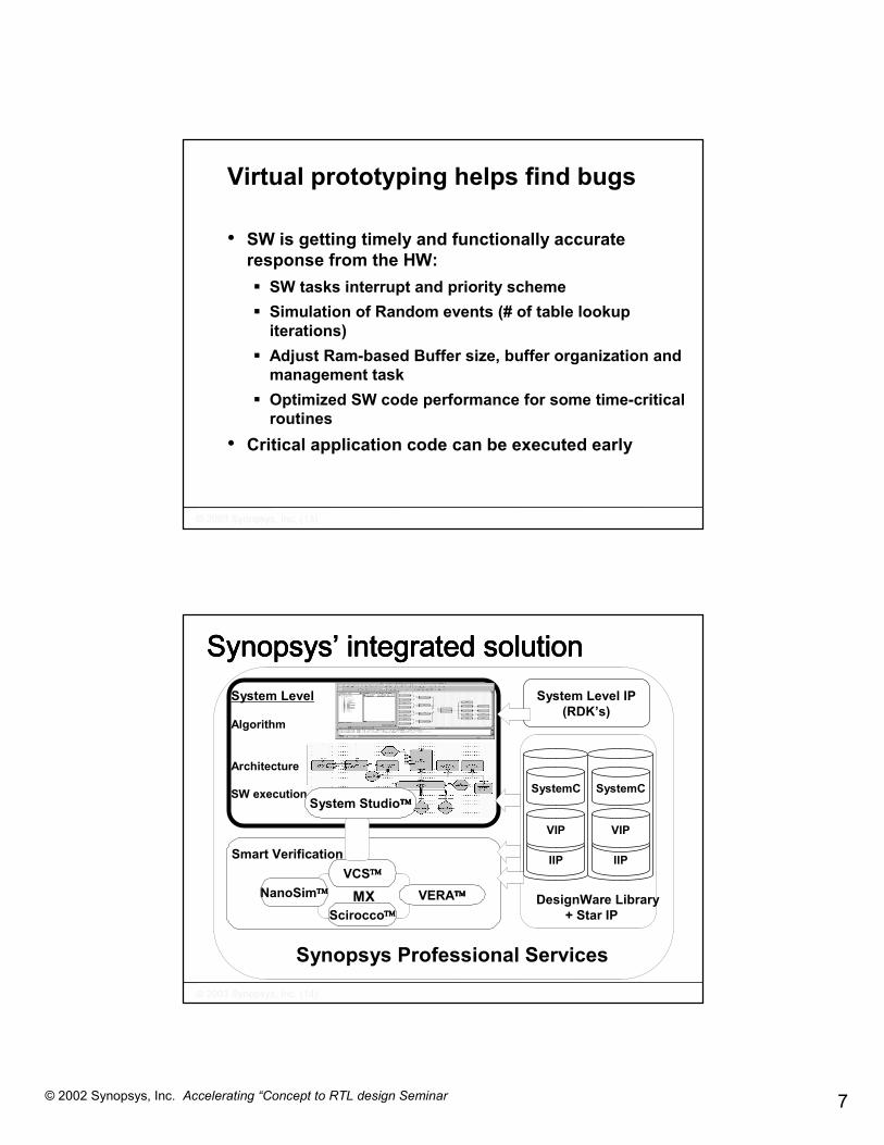
• SW is getting timely and functionally accurate response from the HW:� SW tasks interrupt and priority scheme� Simulation of Random events (# of table lookup
iterations)� Adjust Ram-based Buffer size, buffer organization and
management task � Optimized SW code performance for some time-critical
routines• Critical application code can be executed early
Virtual prototyping helps find bugs
��������������� ������������������
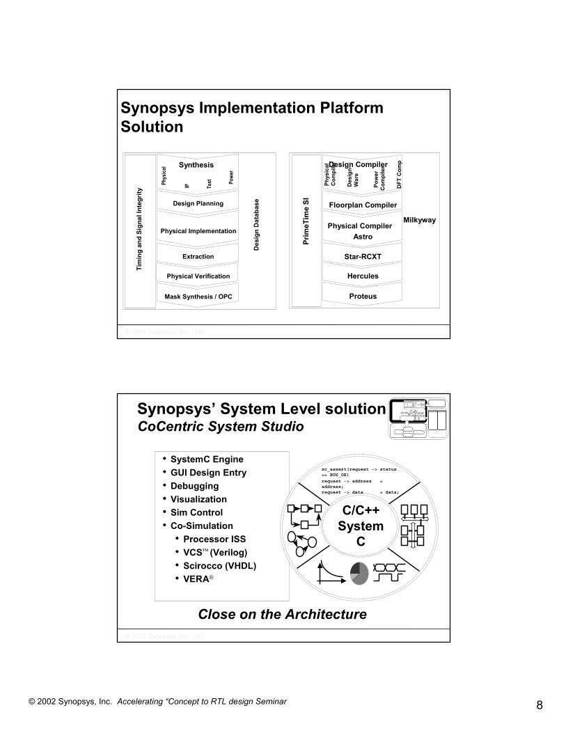
Synopsys Professional Services
������������������������������������ ���� �������������� �������������� �������������� ����������
Smart Verification
MXVCS
NanoSim VERAScirocco
System Level
Algorithm
Architecture
SW executionSystem Studio
IIP
VIP
SystemC
IIP
VIP
SystemC
DesignWare Library + Star IP
System Level IP(RDK’s)
8© 2002 Synopsys, Inc. Accelerating “Concept to RTL design Seminar
��������������� ������������������
Synopsys Implementation Platform Solution
Physical Implementation
Design Planning
Extraction
Physical Verification
Mask Synthesis / OPC
Des
ign
Dat
abas
e
Tim
ing
and
Sign
al In
tegr
ity
Test Po
wer
Phys
ical Synthesis
IP
Physical Compiler Astro
Floorplan Compiler
Star-RCXT
Hercules
Proteus
Milkyway
Prim
eTim
e SI
Design Compiler
DFT
Com
p
Pow
er
Com
pile
r
Des
ign-
War
e
Phys
ical
Com
pile
r
��������������� ������������������
Synopsys’ System Level solutionCoCentric System Studio
• SystemC Engine• GUI Design Entry• Debugging• Visualization• Sim Control• Co-Simulation
• Processor ISS• VCS™ (Verilog)• Scirocco (VHDL)• VERA®
sc_assert(request -> status== BUS_OK)
request -> address =address;request -> data = data;
C/C++System
C
Close on the Architecture

9© 2002 Synopsys, Inc. Accelerating “Concept to RTL design Seminar
��������������� ������������������
Synopsys’ Smart VerificationVCS. Scirocco, Vera
Controller
CPUROM
3rd PartyIP
UserDefinedLogic
Interface
Analog
Synopsys Solution
Simulation Testbench& IP
FormalCoverage
Assertions Controller
CPUROM
3rd PartyIP
UserDefinedLogic
Interface
Analog
•Fast RTL simulation•Highest capacity•Stimulus generation•Complex scenarios
•Assertion simulation•Assertion proofs•Profiling tools•Coverage tools
��������������� ������������������
Design & Verification IPThe models you need
SOC & ASICProcessor busesProtocolsNetworking
System LevelWirelessMultimedia
Synopsys IPEssential elements for project success
http://www.synopsys.com/products/designware/ipdir

10© 2002 Synopsys, Inc. Accelerating “Concept to RTL design Seminar
��������������� ������������������
Agenda
• 1.00 p.m. Introduction and Seminar Overview• 1:10 p.m. SOC design challenge and SystemC methodology• 1:40 p.m. Introduce SystemC language• 2:30 p.m. Tea Break <-----------------------------------------------------• 3:00 p.m. The Concept to RTL flow for the SOHO router
� Today’s design – SOHO Router� Architecture SOC design� SW implementation & debug� Moving from Transaction Level Models to RTL � Reaching golden RTL
• 4:30 p.m. Demo: Multiprocessor ARM design for IP Router• 5:00 p.m. Q&A and Wrap up
��������������� ������������������
What is SystemC?
... A language extension to C/C++ to describeand simulate HW/SW systems:� Multiple levels of abstraction� Concurrency� IP reuse methodology� For the SOC design challenge
SystemCLibrary
... A C++ class library to standardizeC-based system modelling
... A basic simulation kernel

11© 2002 Synopsys, Inc. Accelerating “Concept to RTL design Seminar
��������������� ������������������
C/C++ out of the box
• C/C++ does not support� Hardware style communication
• Signals, events, …etc.� Notion of time
• Time sequenced operations� Concurrency
• Hardware and systems are inherently concurrent, ie components operate in parallel
� Reactivity• HW is inherently reactive, it responds to stimuli and is in
constant interaction with its environment, which requires handling of exceptions
� Hardware datatypes• Bit type, bit-vector type, multi-valued logic type, signed
and unsigned integer types and fixed-point types
��������������� ������������������
Extends C/C++ for complex HW/SW systems design SystemC
SystemC Goes Beyond C/C++ & OOP
Extends computational capabilities of C
C++
SW development
Csynthesizable subset
• Separate Communication from Functionality• Separate Data from Control• Concurrency

12© 2002 Synopsys, Inc. Accelerating “Concept to RTL design Seminar
��������������� ������������������
SystemC Language Architecture
C++ Language Standard
Elementary ChannelsSignal, Timer, Mutex, Semaphore, FIFO, etc.
• Time • Concurrency• Modules• Processes• Interfaces• Ports• Channels• Events• Event-driven sim. kernel
Data Types• 4-valued logic (0, 1, X, Z)• 4-valued logic-vectors• Bits and bit-vectors• Arbitrary-precision integers• Fixed-point numbers• C++ user-defined types• C++ built-in types (int, char…)
SystemC 2.0 for different Models of Computation� Static Multi-rate Dataflow
� Dynamic Multi-rate Dataflow
� Communicating Sequential Processes/Control Models
� Discrete Event as used for� RTL hardware modeling� Network modeling (e.g. stochastic or “waiting room”models)� Transaction-based SoC platform modeling
� Kahn Process Networks

13© 2002 Synopsys, Inc. Accelerating “Concept to RTL design Seminar
��������������� ������������������
Open SystemC Initiative roadmapSystem
HardwareSoftware
Bus Cycle AccurateBCA
Cycle AccurateRTL
AbstractRTOSTask Partitioning
RTOSTarget RTOS/Core
Untimed Functional
Timed Functional
HW/SW Partitioning
Assign execution time
Refine behavior
Design ExplorationPerformance Analysis
Refine behavior
(2002) SystemC 3.0 SystemC 1.0 (2000)
SystemC 2.0 (2001)
��������������� ������������������
Modeling - A SystemC "System"
� System consists of a set of modules� Modules contain concurrent processes
� Process describes functionality� Processes communicate with each other through channels or events
� Inter-Module communication is through channels
Module Module
System
channelsor
events
channelsor
events Channel(s)
Process
Process
Process
Process

14© 2002 Synopsys, Inc. Accelerating “Concept to RTL design Seminar
Hierarchy� Modules are used to create hierarchy� Top level is not a module but is a SystemC function sc_main()� May instantiate modules inside sc_main()� May instantiate modules inside of other modules
sc_main
b
e f g
k
j
h
dc
instance names
giga
flop
mega
Top_level
module names
e
ModuleInstance
ModuleInstance
Process
Process
Channel
Channel
Channel
Process
Ports
Module
Basic Modeling Structure: Module
Module bodyModule instancesconcurrent processes
Module represents:system, block, board, chip…
Ports represent:interface, pins

15© 2002 Synopsys, Inc. Accelerating “Concept to RTL design Seminar
Basic Modeling Structure: Communication� Interfaces
� Defines set of access methods for a channel � Channels
� Implements an interface's methods� Ports
� Object through which processes access a channel’s interface
Channel Process
Module
Interface ( )
Port/interface binding ( )
Ports ( )
Inter-Module Communication:Channels, Interfaces, Ports� Interface
� Defines set of access methods� Does not provide the implementation of the methods� Purely functional, no data� Examples: sc_fifo_in_if, sc_fifo_out_if
� Channel� Implements an interface's methods
� Can implement one or more interfaces� Container for communication functionality� Example : sc_fifo<T>
� Port� Provides dedicated access methods to a channel� Object through which modules (and hence it's processes) can access a
channel’s interface� Process accesses channel by applying interface methods to port
� Defined in terms of an interface type� Can only be used with channels that implement this interface type
� Example: sc_port<sc_fifo_in_if<T> >

16© 2002 Synopsys, Inc. Accelerating “Concept to RTL design Seminar
Channels: Primitive & Hierarchical
� Primitive channels� No visible structure� No processes� Can not (directly) access other primitive channels
sc_signal<T>, sc_signal_rv<N>sc_fifo<T>, sc_mutex, sc_semaphoresc_buffer<T>
� Hierarchical channels� Modules
� Structure� Processes� Other modules� Can (directly) access other channels
� For modeling complex channels
Channels & Ports
� In general different channels require different interface methods
� Ports are “bound” to an interface� To connect a channel to a port
� Channel must implement the interface the port is bound to� Allows for refinement of channel independent of ports
� Ports may be bound to multiple channels

17© 2002 Synopsys, Inc. Accelerating “Concept to RTL design Seminar
Events and Dynamic Sensitivity
� Event (sc_event) is the basic synchronization object� Events are used to synchronize between processes� Channels use events to implement blocking
� Dynamic sensitivity for triggering processes� Sensitivity list for a process does not need to be defined before
simulation starts - can be altered during simulation� Enabled through events
� Wait ( wait() ) � Processes may wait for an event
� Dynamic sensitivity coupled with ability of process to wait on an event provide for:� Efficient simulation (faster)� Simple modeling at higher levels of abstraction
Simple Example - 1
main.cpp
stimgen.cpp
stimgen.h
adder.cpp
adder.h
monitor.cpp
monitor.h
Adderin1
in2out Response
MonitorreStimulusGenerator
a1
a2
Systems1
s2s3

18© 2002 Synopsys, Inc. Accelerating “Concept to RTL design Seminar
Simple Example - 2#include "systemc.h"#include "adder.h"#include "stimgen.h"#include "monitor.h"
int sc_main(int argc, char *argv[ ]){// Create fifos with a depth of 10sc_fifo<int> s1(10);sc_fifo<int> s2(10);sc_fifo<int> s3(10);
// Module instantiations// Stimulus Generatorstimgen stim("stim");stim(s1, s2);
// Adderadder add("add");add(s1, s2, s3);
// Response Monitormonitor mon ("mon");mon.re(s3);
// Start simulationsc_start();
return 0;}
main.cpp
stimgen.cpp
stimgen.h
adder.cpp
adder.h
monitor.cpp
monitor.h
Adderin1
in2out Response
MonitorreStimulusGenerator
a1
a2
Systems1
s2s3
Simple Example - 3
// header file adder.hSC_MODULE(adder) {// Input portssc_port<sc_fifo_in_if<int> > in1;sc_port<sc_fifo_in_if<int> > in2;
// Output portssc_port<sc_fifo_out_if<int> > out;
// sync process for addervoid adder_proc ();
// Module constructorSC_CTOR(adder) {
SC_THREAD(adder_proc);}
}
main.cpp
stimgen.cpp
stimgen.h
adder.cpp
adder.h
monitor.cpp
monitor.h
Adderin1
in2out Response
MonitorreStimulusGenerator
a1
a2
Systems1
s2s3
19© 2002 Synopsys, Inc. Accelerating “Concept to RTL design Seminar
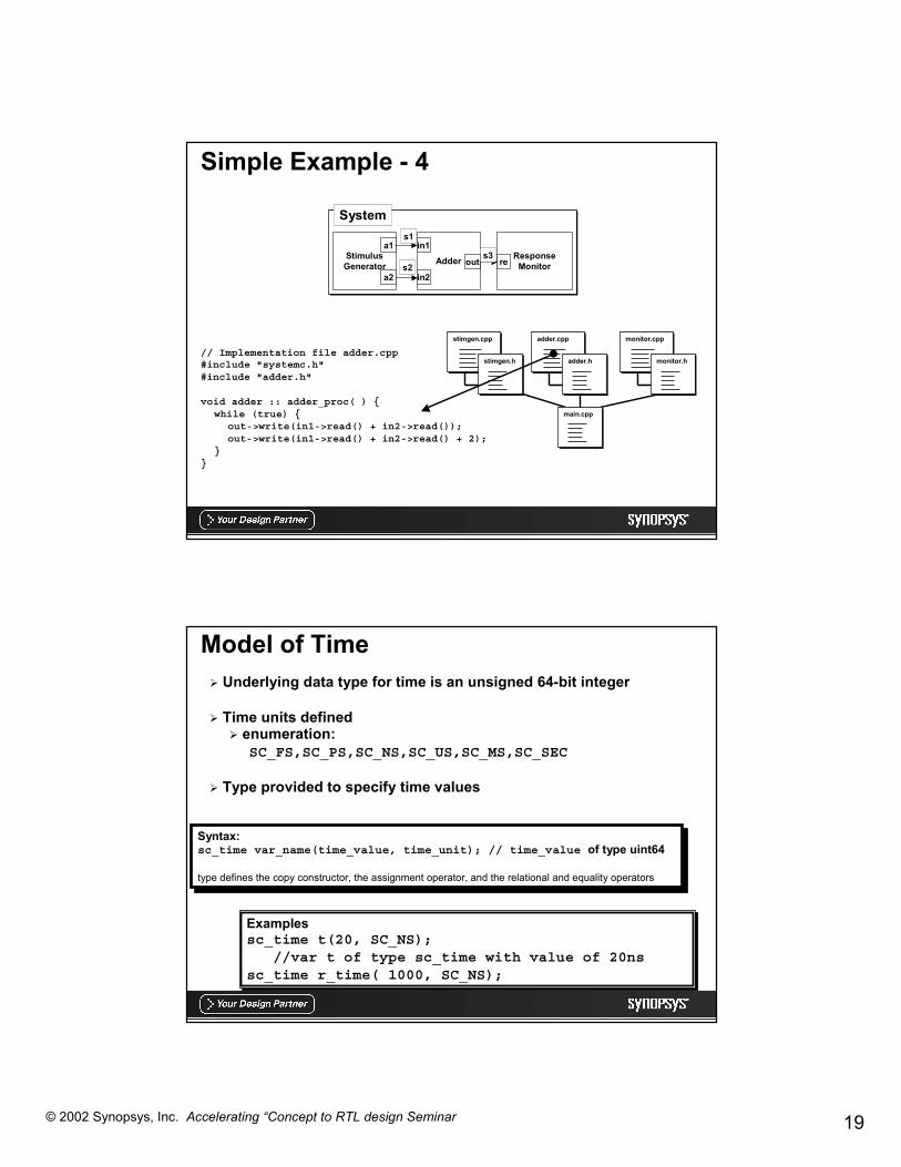
Simple Example - 4
// Implementation file adder.cpp#include "systemc.h"#include "adder.h"
void adder :: adder_proc( ) {while (true) {
out->write(in1->read() + in2->read());out->write(in1->read() + in2->read() + 2);
}}
main.cpp
stimgen.cpp
stimgen.h
adder.cpp
adder.h
monitor.cpp
monitor.h
Adderin1
in2out Response
MonitorreStimulusGenerator
a1
a2
Systems1
s2s3
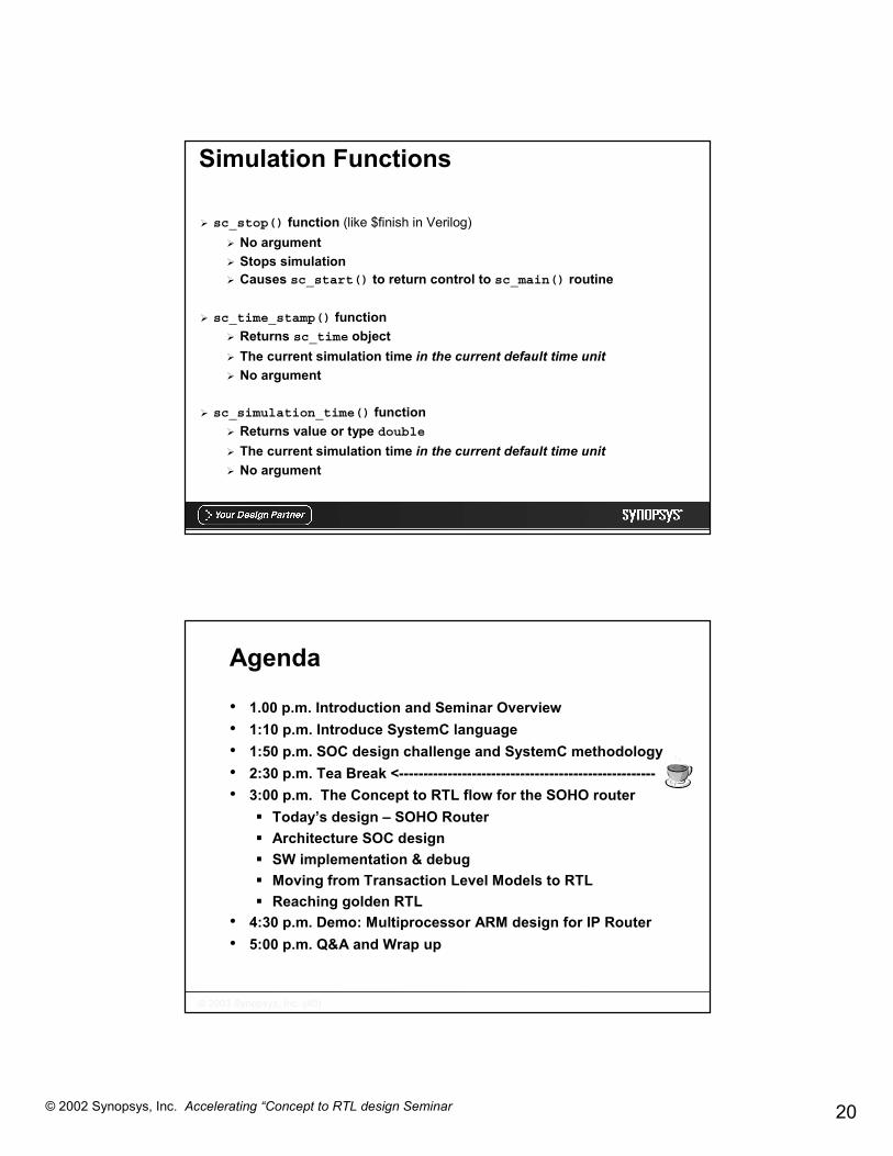
Model of Time� Underlying data type for time is an unsigned 64-bit integer
� Time units defined� enumeration:
SC_FS,SC_PS,SC_NS,SC_US,SC_MS,SC_SEC
� Type provided to specify time values
Syntax:sc_time var_name(time_value, time_unit); // time_value of type uint64
type defines the copy constructor, the assignment operator, and the relational and equality operators
Examplessc_time t(20, SC_NS);
//var t of type sc_time with value of 20nssc_time r_time( 1000, SC_NS);
20© 2002 Synopsys, Inc. Accelerating “Concept to RTL design Seminar
Simulation Functions
� sc_stop() function (like $finish in Verilog)� No argument� Stops simulation� Causes sc_start() to return control to sc_main() routine
� sc_time_stamp() function� Returns sc_time object� The current simulation time in the current default time unit� No argument
� sc_simulation_time() function� Returns value or type double� The current simulation time in the current default time unit� No argument
��������������� ������������������
Agenda
• 1.00 p.m. Introduction and Seminar Overview • 1:10 p.m. Introduce SystemC language• 1:50 p.m. SOC design challenge and SystemC methodology• 2:30 p.m. Tea Break <-----------------------------------------------------• 3:00 p.m. The Concept to RTL flow for the SOHO router
� Today’s design – SOHO Router� Architecture SOC design� SW implementation & debug� Moving from Transaction Level Models to RTL � Reaching golden RTL
• 4:30 p.m. Demo: Multiprocessor ARM design for IP Router• 5:00 p.m. Q&A and Wrap up

21© 2002 Synopsys, Inc. Accelerating “Concept to RTL design Seminar
��������������� ������������������
SOHO router products on the market
Communication processorsbased on AMBA bus architectures
ADSL routing solutions address the SOHO needs
��������������� ������������������
Our SOHO router system
ADSLtransceiver
CommunicationProcessor
Ethernet 10/100 base T
Local loop
Central officeDSLAM
SOHO equipment
USB
SOHO Router
ADSL transceiver = MC145650 or equivalentEthernet transceiver = TDK 78Q2120B or equivalent
SDRAM
Ethernettransceiver
MII
22© 2002 Synopsys, Inc. Accelerating “Concept to RTL design Seminar
��������������� ������������������
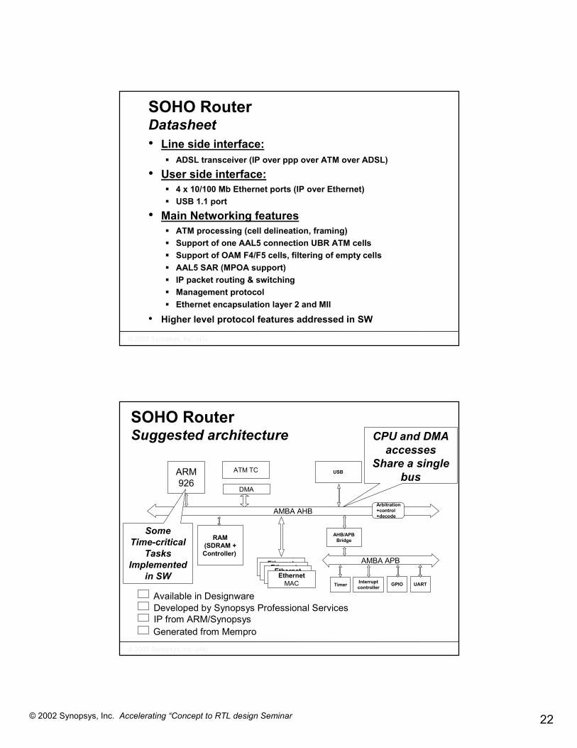
SOHO Router Datasheet• Line side interface:
� ADSL transceiver (IP over ppp over ATM over ADSL)
• User side interface:� 4 x 10/100 Mb Ethernet ports (IP over Ethernet)� USB 1.1 port
• Main Networking features� ATM processing (cell delineation, framing) � Support of one AAL5 connection UBR ATM cells� Support of OAM F4/F5 cells, filtering of empty cells� AAL5 SAR (MPOA support)� IP packet routing & switching� Management protocol� Ethernet encapsulation layer 2 and MII
• Higher level protocol features addressed in SW
��������������� ������������������
SOHO Router Suggested architecture
ARM926
Ethernet10/100
RAM(SDRAM +Controller)
AMBA AHB
AMBA APB
Arbitration+control+decode
AHB/APBBridge
USBATM TC
DMA
InterruptcontrollerTimer GPIO UART
Ethernet10/100Ethernet
10/100EthernetMAC
Available in DesignwareDeveloped by Synopsys Professional ServicesIP from ARM/SynopsysGenerated from Mempro
CPU and DMA accesses
Share a single bus
Some Time-critical
Tasks Implemented
in SW

23© 2002 Synopsys, Inc. Accelerating “Concept to RTL design Seminar
��������������� ������������������
Functional data path description
• Shown here one direction (ADSL to Ethernet) • Possible architecture bottle necks • These blocks share the AMBA bus and the
Ram device (single port)• The time-critical Networking tasks and
Interrupt service routines (ATM, Ethernet) are executed on the same processor core as the application SW (upper protocol layers)
IPWB
ATMWB
ATMTC
RAMATM buffer ARM
926
RAMIP
buffer
Ether-net
MAC
Ether-netL2
IPWB
Design
SWAAL5
SWAAL5
��������������� ������������������
SOHO Router Principle of operations (downstream traffic only)
1. ATM cell received2. ATM FIFO high threshold
reached, ATM DMA transfer to RAM buffer
3. ATM DMA triggers IT_ATM4. SW reads next ATM buffer
from RAM5. AAL5 SW Processing6. SW writes Ethernet buffer to
RAM7. Ethernet packets send on MII8. MII Collision detected9. Ethernet FIFO low threshold
reached, Ethernet DMA transfer from RAM buffer
10. Ethernet DMA triggers IT_ETHERNET
ATM IN RAM ARM926
Ethernet
OUT
1 23
4 1078
69
5
71
1
Critical data transfer on the AMBA BUS
24© 2002 Synopsys, Inc. Accelerating “Concept to RTL design Seminar
��������������� ������������������
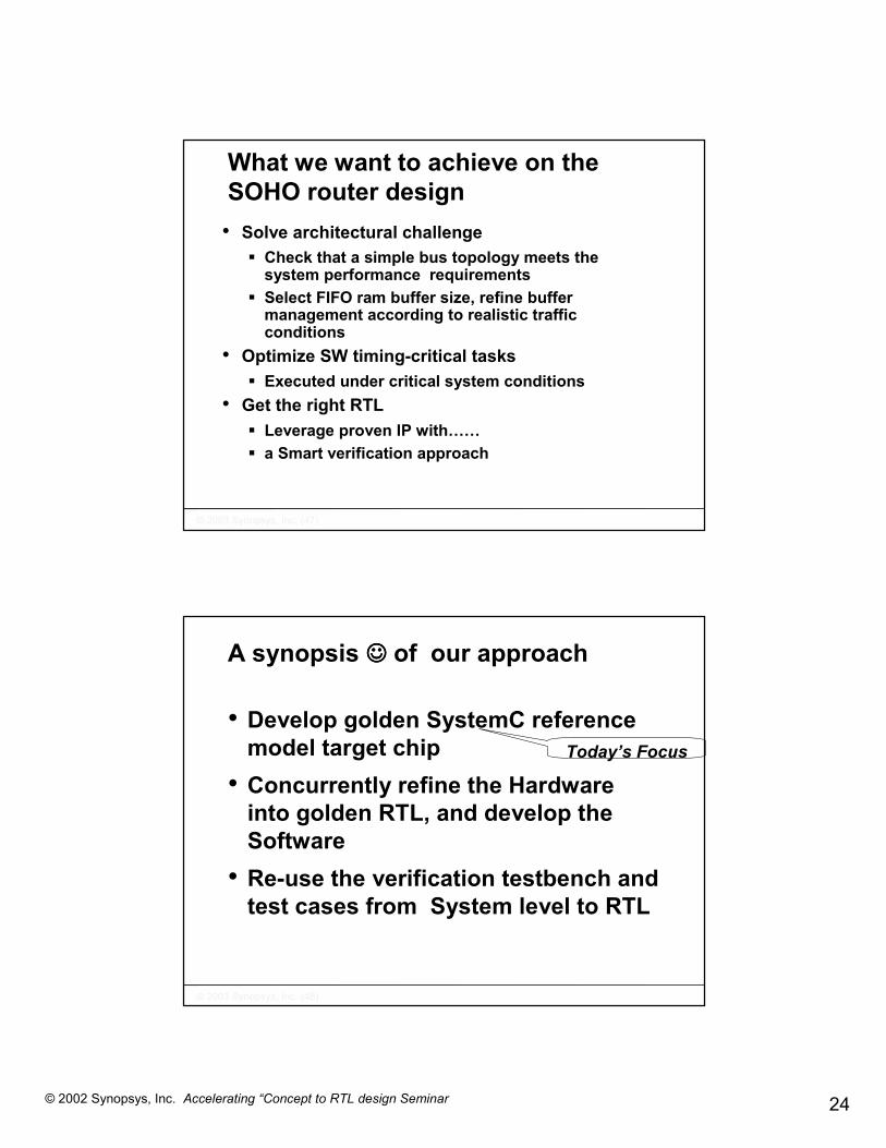
What we want to achieve on the SOHO router design • Solve architectural challenge
� Check that a simple bus topology meets the system performance requirements
� Select FIFO ram buffer size, refine buffer management according to realistic traffic conditions
• Optimize SW timing-critical tasks� Executed under critical system conditions
• Get the right RTL� Leverage proven IP with……� a Smart verification approach
��������������� ������������������
A synopsis ☺☺☺☺ of our approach
• Develop golden SystemC reference model target chip
• Concurrently refine the Hardware into golden RTL, and develop the Software
• Re-use the verification testbench and test cases from System level to RTL
Today’s Focus

25© 2002 Synopsys, Inc. Accelerating “Concept to RTL design Seminar
��������������� ������������������
reuse
Design Flow Overview
Architecture design
HW designSW design
PhysicalDesign
• Architectural SOC Executable specifications described at Transaction level (TLM)
• Catch bugs while there are still cheap to fix• Check Chip Level Architecture performance
• SW development and testingis performed early on a virtual prototype of the System
• Get the HW accurate response, with an acceptable simulation speed
• HW design uses TLM reference platform as the main verification testbench
• Reuse the same (successively refined) verification environment
• Add remaining interfaces• Add HDL Assertions• Perform Coverage metrics
Systemspecifications
��������������������������������
��������������� ������������������
Agenda
• 1.00 p.m. Introduction and Seminar Overview • 1:10 p.m. Introduce SystemC language• 1:50 p.m. SOC design challenge and SystemC methodology• 2:30 p.m. Tea Break <-----------------------------------------------------• 3:00 p.m. The Concept to RTL flow for the SOHO router
� Today’s design – SOHO Router� Architecture SOC design� SW implementation & debug� Moving from Transaction Level Models to RTL � Reaching golden RTL
• 4:30 p.m. Demo: Multiprocessor ARM design for IP Router• 5:00 p.m. Q&A and Wrap up
26© 2002 Synopsys, Inc. Accelerating “Concept to RTL design Seminar
��������������� ������������������
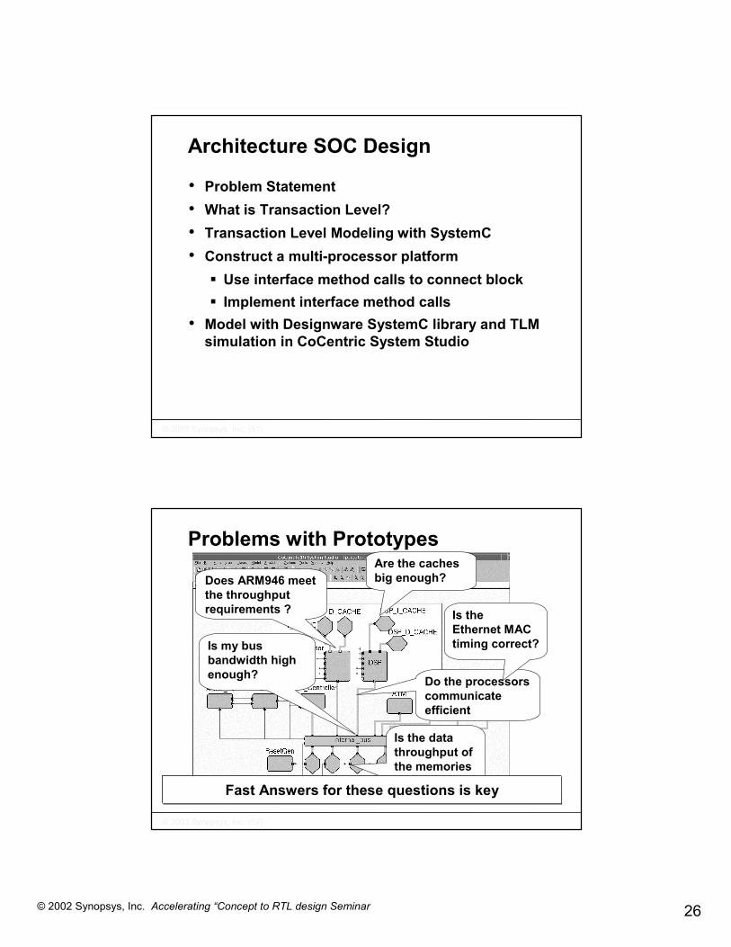
Architecture SOC Design
• Problem Statement• What is Transaction Level?• Transaction Level Modeling with SystemC• Construct a multi-processor platform
� Use interface method calls to connect block� Implement interface method calls
• Model with Designware SystemC library and TLM simulation in CoCentric System Studio
��������������� ������������������
Problems with Prototypes
Is my bus bandwidth high enough?
Does ARM946 meet the throughput requirements ?
Are the caches big enough?
Do the processors communicate efficient
Is theEthernet MAC timing correct?
Is the data throughput of the memories high enough?Fast Answers for these questions is key

27© 2002 Synopsys, Inc. Accelerating “Concept to RTL design Seminar
��������������� ������������������
Specification Questions
cell loss ?bit error rate ?
bus bandwidth ?Cache size ?
bus protocol ?pin behavior ?
audio quality ?bit error rate ?
bus bandwidth ?cache size ?
Transaction Level for multi-processor platform analysis
TransactionLevel
cycle buscycle
latencyannotation
untimedsubcycle
RTL
FunctionalLevel
SimulationSpeed1 10x
100x
1000x
��������������� ������������������
Requirements for Platform Modeling – Block Level
• Efficient modeling of interaction between processors, buses, memory and HW co-processors
• Cycle accuracy in crucial• High simulation speed• Efficient way of concurrent modeling• Efficient way to extend systems

28© 2002 Synopsys, Inc. Accelerating “Concept to RTL design Seminar
��������������� ������������������
Requirements for Platform Modeling – System Level
• System assembling� Fast� Configurable blocks needed� Easy access to configuration� Documentation
• Analysis� Easy way to chance platform configuration� visualization� Easy access to results for further processing� Interactive simulation and regressions
��������������� ������������������
Architecture SOC Design
• Problem Statement• What is Transaction Level?• Transaction Level Modeling with SystemC• Construct a multi-processor platform
� Use interface method calls to connect block� Implement interface method calls
• Model with Designware SystemC library and TLM simulation in CoCentric System Studio

29© 2002 Synopsys, Inc. Accelerating “Concept to RTL design Seminar
��������������� ������������������
Data Abstraction
Many designers start with data abstraction
struct my_packets{sc_int<8> dest_addressbool some_flags…..
}
Scheduler AnalysisRouting
Source
Source
SourceHW signal
��������������� ������������������
� Model does not answer these questions
Analysis Questions
Scheduler AnalysisRouting
Source
Source
Source
What scheduling algorithm do I need?
What is the scheduler throughput?
What is the maximum and/or average cell delay?
Is a buffer size 10 enough for the targeted cell lose ratio?

30© 2002 Synopsys, Inc. Accelerating “Concept to RTL design Seminar
��������������� ������������������
enabledata
sc_signals
Final Model with Data Abstraction
t
t
ready
Scheduler
FIFO T1
clock
• inefficient way of connecting blocks• fixed to one implementation (FIFO)• no flexibility
Scheduler AnalysisRouting
Source
Source
Source
Output rate = T1
��������������� ������������������
The Mistakes
• Mistake 1: Data abstraction does not solve the problem� Model does not allow to answer the
specification questions • Mistake 2: Using HW signals as
communication mechanism� HW signals are specific for reactive HW� Signal communication mechanism not
suitable for high level models

31© 2002 Synopsys, Inc. Accelerating “Concept to RTL design Seminar
��������������� ������������������
What can be done better?
Analysis
FIFOSource
Source
Source
Scheduler Routing
communication
Communication functionality:write, if buffer full wait until buffer freeread, if value availablebuffer management:
move pointers after each read and writecheck for full and empty
FIFOBehavior
clock
��������������� ������������������
Communication implementation
What can be done better?
Analysis
FIFOSource
Source
Source
Scheduler Routing
Communication abstraction
clock
� Efficient way of connecting blocks� Efficient way of develop models� Efficient way of extend systems and allow successive refinement

32© 2002 Synopsys, Inc. Accelerating “Concept to RTL design Seminar
��������������� ������������������
What is Transaction Level?
Analysis
Source
Source
Source
Scheduler Routing
Transaction level is not only data abstraction, it is also communication abstraction
clock
��������������� ������������������
Why Transaction Level Communication Abstraction?
• Reduce modeling effort for communication
• Increase simulation speed• Reduce the effort to develop and extend
complex systems

33© 2002 Synopsys, Inc. Accelerating “Concept to RTL design Seminar
��������������� ������������������
Architecture SOC Design
• Problem Statement• What is Transaction Level?• Transaction Level Modeling with SystemC• Construct a multi-processor platform
� Use interface method calls to connect block� Implement interface method calls
• Model with Designware SystemC library and TLM simulation in CoCentric System Studio
��������������� ������������������
adder_reg
RT-Level SystemC
add reg
#include “systemc.h”
SC_MODULE(adder_reg) {
};
sc_in<sc_int<8> > a; // input portsc_in<sc_int<8> > b; // input portsc_out<sc_int<9> > c; // output portsc_in<bool> clk; // clock
//Internal Signalssc_signal<sc_int<9> > temp;
// Adder Processvoid add(){ temp = a + b; }
// Register update processvoid reg(){ c = temp; }
SC_METHOD(add);sensitive << a << b;
// ConstructorSC_CTOR(adder_reg) {
}
SC_METHOD(reg);sensitive_pos << clk;
ab
c
clockInternal Communication
ParallelismFunctionality
Instances• Type• Sensitivity
Full RTL Guidewww.synopsys.com/sld
StructureI/O
adder_reg.c
temp

34© 2002 Synopsys, Inc. Accelerating “Concept to RTL design Seminar
��������������� ������������������
channel
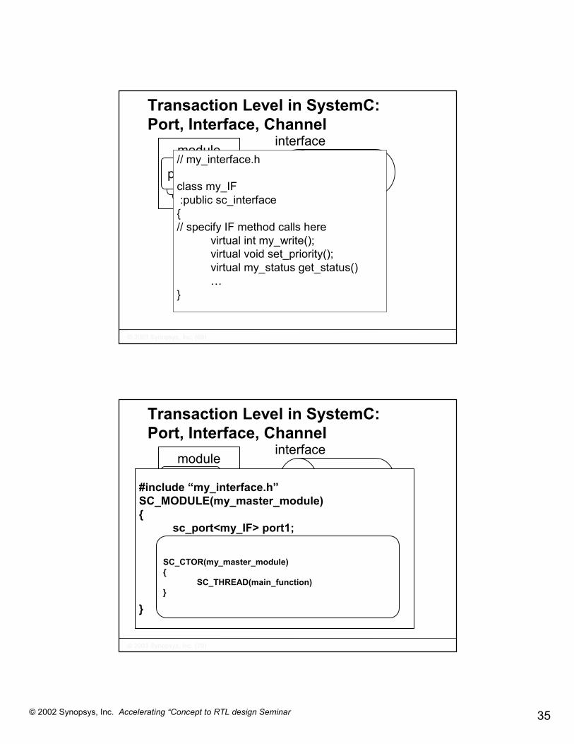
Transaction Level in SystemC: Port, Interface, Channel
module
port1processprocessprocess
interface
#include “my_interface.h”SC_MODULE(my_master_module){
sc_port<my_if> port1...
}
// my_interface.h
class my_if:public sc_interface
{// specify interface method calls here
virtual int my_write(&T);virtual void set_priority();virtual status get_status()…
}
my_master_module::main_function() {...port1->my_write(&data);
...}
#include “my_interface.h”SC_MODULE(my_master_module){
sc_port<my_if> port1;
}
SC_CTOR(my_master_module){
SC_THREAD(main_function)}
��������������� ������������������
channel
Transaction Level in SystemC: Port, Interface, Channel
module
port1processprocessprocess
interface
#include “my_interface.h”SC_MODULE(my_master_module){
sc_port<my_if> port1...
}
add
use
35© 2002 Synopsys, Inc. Accelerating “Concept to RTL design Seminar
��������������� ������������������
channel
Transaction Level in SystemC: Port, Interface, Channel
module
port1processprocessprocess
interface// my_interface.h
class my_IF:public sc_interface
{// specify IF method calls here
virtual int my_write();virtual void set_priority();virtual my_status get_status()…
}
��������������� ������������������
channel
Transaction Level in SystemC: Port, Interface, Channel
module
port1processprocessprocess
interface
#include “my_interface.h”SC_MODULE(my_master_module){
sc_port<my_IF> port1;
}
SC_CTOR(my_master_module){
SC_THREAD(main_function)}

36© 2002 Synopsys, Inc. Accelerating “Concept to RTL design Seminar
��������������� ������������������
channel
Transaction Level in SystemC: Port, Interface, Channel
module
port1processprocessprocess
interface
my_master_module::main_function() {...port1->my_write();
...}
��������������� ������������������
What’s so cool about SystemC Transaction-Level Modeling?
It is …• Most efficient way of modeling communication
between different components in a system• easy to use• fast
� use of Interface Method Calls (IMC) ⇒⇒⇒⇒ function calls instead of HW signals and control FSMs
• easy to develop and extend
37© 2002 Synopsys, Inc. Accelerating “Concept to RTL design Seminar
��������������� ������������������
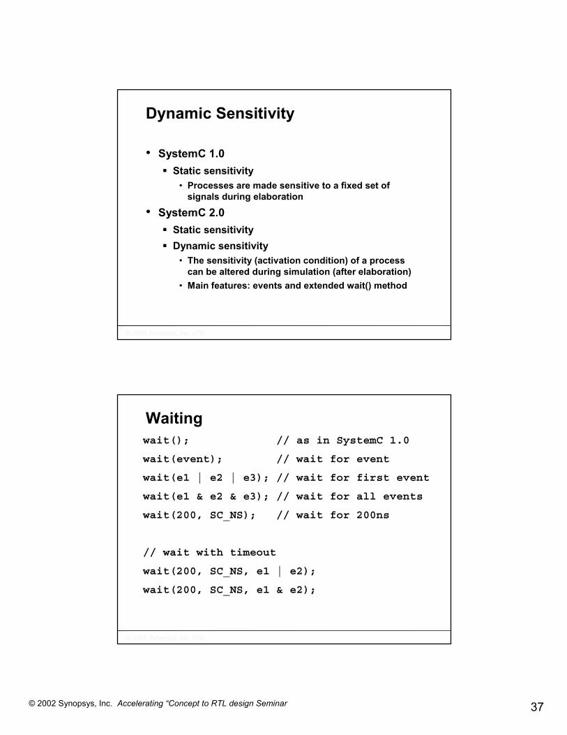
Dynamic Sensitivity
• SystemC 1.0� Static sensitivity
• Processes are made sensitive to a fixed set of signals during elaboration
• SystemC 2.0� Static sensitivity� Dynamic sensitivity
• The sensitivity (activation condition) of a process can be altered during simulation (after elaboration)
• Main features: events and extended wait() method
��������������� ������������������
Waitingwait(); // as in SystemC 1.0
wait(event); // wait for event
wait(e1 | e2 | e3); // wait for first event
wait(e1 & e2 & e3); // wait for all events
wait(200, SC_NS); // wait for 200ns
// wait with timeout
wait(200, SC_NS, e1 | e2);
wait(200, SC_NS, e1 & e2);

38© 2002 Synopsys, Inc. Accelerating “Concept to RTL design Seminar
��������������� ������������������
TLM Multi-Processor Example
µC
GPIO
channel
µP DSP
Mem
��������������� ������������������
Bus Example – Add Timing
GPIO Mem
channel
clockµC µP DSP
39© 2002 Synopsys, Inc. Accelerating “Concept to RTL design Seminar
��������������� ������������������
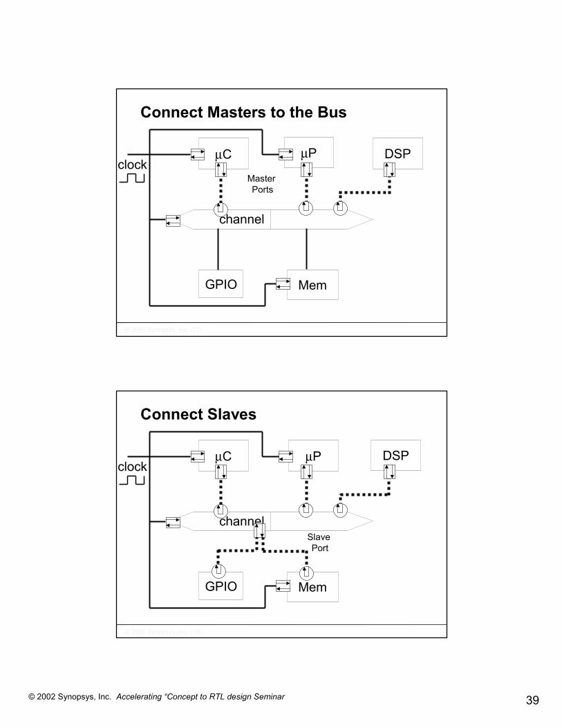
µC µP DSP
Connect Masters to the Bus
GPIO Mem
channel
clockMaster Ports
��������������� ������������������
µP DSPµC
Connect Slaves
GPIO Mem
channel
clock
Slave Port

40© 2002 Synopsys, Inc. Accelerating “Concept to RTL design Seminar
��������������� ������������������
DSPµPµC
Extract Arbitration
GPIO Mem
channel
clock
arbiterArbiterPorts
Key components are the interface method calls (IMC)
��������������� ������������������
Why Interface Files? // my_interface.h
class my_IF:public sc_interface{// specify IF access function here
virtual int my_write();virtual void set_priority();virtual my_status get_status()…
Key language element forcommunication abstraction
• Virtual declaration -> IMC declaration, but no implementation
� Separates declaration from implementation� Separates communication from functionality
• Key source of information• Block -> specifies access methods• Channels -> required implementation

41© 2002 Synopsys, Inc. Accelerating “Concept to RTL design Seminar
��������������� ������������������
AHB / APBBridge
DATE 03: New TL modeling standard
AMBA AHB (multi-layer)
AMBA APB
Other Peripheralse.g., Timer, R&P
InterruptController
AHBMonitor
APBMonitorGeneric
Slave(ex: memory
model)
Decoder
Generic Master
(ex: stimuligenerator)
ARM926EJ-S™processor
Arbiter
ARM946E-S™processor
Making your own TL models fit to Standard IP
ApplicationSpecific
ComponentAMBA SystemC Transfer-Layer
Interface Specification
��������������� ������������������
Architecture SOC Design
• Problem Statement• What is Transaction Level?• Transaction Level Modeling with SystemC• Construct a multi-processor platform
� Use interface method calls to connect block� Implement interface method calls
• Model with Designware SystemC library and TLM simulation in CoCentric System Studio

42© 2002 Synopsys, Inc. Accelerating “Concept to RTL design Seminar
��������������� ������������������
Add Master to a Bus-based System
portinterface
existing bus infrastructure
portinterface
existing bus infrastructure
Traffic Generator
��������������� ������������������
Master: Header File

43© 2002 Synopsys, Inc. Accelerating “Concept to RTL design Seminar
��������������� ������������������
Simple Bus Interface File#include <systemc.h>#include "simple_bus_types.h"class simple_bus_blocking_if \\ blocking interface
: public virtual sc_interface{ public:virtual simple_bus_status burst_read(unsigned int unique_priority
, int *data, unsigned int start_address, unsigned int length = 1, bool lock = false) = 0;
virtual simple_bus_status burst_write(unsigned int unique_priority, int *data, unsigned int start_address, unsigned int length = 1, bool lock = false) = 0;
}; // end class simple_bus_blocking_if
��������������� ������������������
Master: Source File
Read- IMC
Write - IMC

44© 2002 Synopsys, Inc. Accelerating “Concept to RTL design Seminar
��������������� ������������������
Analyze Architecture
Configuration: memory address space, # memory wait statementsbus bandwidth , Master priorityMaster latency ….
��������������� ������������������
Master: ConstructorConfigurable
Master

45© 2002 Synopsys, Inc. Accelerating “Concept to RTL design Seminar
��������������� ������������������
Configure System
Priority
Memory_access = new Memory_access(“Memory_access”,4, 0x4c, false, 300);
Master_latency
��������������� ������������������
Configure System

46© 2002 Synopsys, Inc. Accelerating “Concept to RTL design Seminar
��������������� ������������������
Run Architecture Exploration
arch_regressions.scf:
unix> Sim.x –control arch_regressions.scf
��������������� ������������������
Analyze Results

47© 2002 Synopsys, Inc. Accelerating “Concept to RTL design Seminar
��������������� ������������������
Implementation Steps
1. Include interface header file#include simple_bus_blocking_if.h
2. Specify port with interface typesc_port<simple_bus_blocking_if> my_new_port
3. Check interface header file for IMCs4. Use IMCs
my_new_port->burst_read (start_addr,&data,num_value, mode);(for processor integration:
check Synopsys’ transaction level processor modeling guide)5. Add parameters to configure system for exploration
• Constructor • Parameters
6. Use Tcl scripts to run simulations with various configurations7. Analyze architecture performance
��������������� ������������������
DesignWare SystemC Library
Memory
Data Bus
ProgramMemory
Instruction Bus
ARM 926Tightly coupledMemory (TCM)
InterconnectMatrix (IMC)
Arbiter
AddressDecoder

48© 2002 Synopsys, Inc. Accelerating “Concept to RTL design Seminar
��������������� ������������������
DesignWare AMBA AHB Components
• AHB bus with external arbiter and decoder• Interconnection matrix for AMBA multilayer
support• AHB bus monitor• Processors (ARM 926, ARM 946)• Pin Level adaptors• Example masters and slaves• Example AHB platforms
��������������� ������������������
DesignWare AMBA APB Components
• AHB-APB bridge with APB bus• APB bus monitor• Pin Level adaptors• APB peripherals
� Remap and pause controller� Interrupt controller� APB timer
• Example AHB/APB platforms

49© 2002 Synopsys, Inc. Accelerating “Concept to RTL design Seminar
��������������� ������������������
Summary – use IMCs
• Easy to connect blocks to the TLM bus infrastructures • Efficient way to design complex systems• Easy to use configuration mechanisms via constructor
arguments and CCSS_PARAMETERS • Comfortable configuration, simulation and analyze of
your multi-processor architecture with simulation control files
• Use System Studio to interact with the executable and visualize results
• With System Studio information flows nicely from block developer and block user
��������������� ������������������
Architecture SOC Design
• Problem Statement• What is Transaction Level?• Transaction Level Modeling with SystemC• Construct a multi-processor platform
� Use interface method calls to connect block� Implement interface method calls
• Model with Designware SystemC library and TLM simulation in CoCentric System Studio

50© 2002 Synopsys, Inc. Accelerating “Concept to RTL design Seminar
��������������� ������������������
GPIOMem
µPµC
Bus Example Transaction Level Model
arbiterchannel
clockDSP
channel
mem GPIO
arbiter
��������������� �������������������
Connect Slave Blocks
Tasks to implement slaves as interface method calls: 1. Define IMCs2. Implement IMCs
� fast mem� slow mem� slave pin adapter
3. Use IMCs in calling instance• Add slave port to bus (see master integration)
> sc_port<memory_slave_if> new_slave_port;• Call IMC in the bus to access slave
> read( &data, address);
Successive refinement

51© 2002 Synopsys, Inc. Accelerating “Concept to RTL design Seminar
��������������� �������������������
Define Interface Method Calls
Memory Slave Example IMCs� Read from memory -> read(data*, address)� Write to memory -> write(data*, address)� Build address range -> addr_range (start*, end*)
• Code example interface file
• d
class memory_slave_if: public sc_interface
{public:
// Slave interface method calls declarationvirtual status read(int *data, unsigned int address) = 0;virtual status write(int *data, unsigned int address) = 0;virtual void addr_range(unsigned int *start_ad, unsigned int *end_ad) = 0;
}; // end class memory_slave_if
��������������� �������������������
Implement Interface Method Calls- fast mem (header file)
slave 1fast mem
slave 1fast mem
To bus
class fast_mem: public memory_slave_if, public sc_module{public:
SC_HAS_PROCESS(fast_mem)// constructorfast_mem(sc_module_name name_ ,
unsigned int start_address, unsigned int end_address)
: sc_module(name_) , m_start_address(start_address) , m_end_address(end_address)
{sc_assert(m_start_address <= m_end_address); unsigned int size = (m_end_address-m_start_address+1)/4;MEM = new int [size];for (unsigned int i = 0; i < size; ++i)
MEM[i] = 0;}

52© 2002 Synopsys, Inc. Accelerating “Concept to RTL design Seminar
��������������� �������������������
Implement Interface Method Calls - fast mem (cont.)
// destructor~fast_mem();
// slave interface method callsstatus read(int *data, unsigned int address);status write(int *data, unsigned int address);void add_range(unsigned int *start_a, unsigned int *end_a);
private:int * MEM;unsigned int m_start_address;unsigned int m_end_address;
}; // end module fast_mem
slave 1fast mem
��������������� �������������������
Implement Interface Method Calls - fast mem (source file)
inline status fast_mem::read(int *data, unsigned int address){
*data = MEM[(address - m_start_address)/4];return SIMPLE_BUS_OK;
}
inline status fast_mem::write(int *data, unsigned int address){
MEM[(address - m_start_address)/4] = *data;return SIMPLE_BUS_OK;
}
inline void fast_mem::range_add(unsigned int *start_a, unsigned int *end_a) {
*start_a = m_start_address;*end_a = m_end_address;
}
inline fast_mem::~fast_mem(){ delete [] MEM; }
slave 1fast mem

53© 2002 Synopsys, Inc. Accelerating “Concept to RTL design Seminar
��������������� �������������������
Implement Interface Method Calls - slow mem slave 2
slow mem
slave 2slow memClock
class slow_mem: public memory_slave_if, public sc_module{public:// processesvoid wait_loop();// portssc_in_clk clockSC_HAS_PROCESS(slow_mem);// constructor
slow_mem(sc_module_name name_ , ….. unsigned int nr_wait_states)
: sc_module(name_) , m_start_address(start_address) , end_address(end_address), m_wait_count(-1){
SC_METHOD(wait_loop);dont_initialize();sensitive_pos << clock;sc_assert(m_start_address <= m_end_address);….
MEM[i] = 0;}
��������������� �������������������
Implement Interface Method Calls – slow mem (cont.) slave 2
slow mem
// destructor~slow_mem();
// slave interface method callsstatus read(int *data, unsigned int address);status write(int *data, unsigned int address);void add_range(unsigned int *start_a, unsigned int *end_a);
private:int * MEM;unsigned int m_start_address;unsigned int m_end_address;unsigned int m_wait_count;
}; // end module slow_mem

54© 2002 Synopsys, Inc. Accelerating “Concept to RTL design Seminar
��������������� �������������������
Implement Interface Method Calls – slow mem (cont.)
inline void slow_mem::wait_loop() {
if (m_wait_count > 0) m_wait_count--;}inline status slow_mem::read(int *data, unsigned int address){// accept a new call if m_wait_count < 0)if (m_wait_count < 0){m_wait_count = m_nr_wait_states;return SIMPLE_BUS_WAIT;
}if (m_wait_count == 0){*data = MEM[(address - m_start_address)/4];return SIMPLE_BUS_OK;
}return SIMPLE_BUS_WAIT; }
inline status slow_mem::write(int *data, unsigned int address) …inline void slow_mem::range_add(…inline slow_mem::~fast_mem() ….
slave 2slow mem
Return statusSIMPLE_BUS_WAITfor n_wait_count cycles
Implement wait_loop
��������������� �������������������
Transaction Level Bus Models• Synopsys’ Simple Bus
� Example implementation as starting point� Generic bus protocol� Limited features, cycle accurate
• Synopsys’ DesignWare AMBA � AMBA bus protocol implementation� Cycle accurate� Pin level adapters, peripherals, ARM, APB and AHB
• OCP (Synopsys, Nokia, TI, Sonics)� Defines communication IMCs� Specifies levels of abstraction

55© 2002 Synopsys, Inc. Accelerating “Concept to RTL design Seminar
��������������� �������������������
Summary – Implement IMCs
• Why is the interface method call concept so cool� parallels implementation of block and channels in
a multi-processor systems� Enhance interface functionality by adding
functions will not break the current design� Elegant refine of communication by adding more
detailed timing� Customization of channel accesses� Compiler already identifies if wrong access
methods used
��������������� �������������������
Architecture SOC Design
• Problem Statement• What is Transaction Level?• Transaction Level Modeling with SystemC• Construct a multi-processor platform
� Use interface method calls to connect block� Implement interface method calls
• Model with Designware SystemC library and TLM simulation in CoCentric System Studio

56© 2002 Synopsys, Inc. Accelerating “Concept to RTL design Seminar
��������������� �������������������
Simulate with System Studio
Model library and graphical entry
System time
Access parameters
��������������� �������������������
System Level Debugging with System Studio
Memory content
Bus transactions: which master, which slave, which activity, at which point in time

57© 2002 Synopsys, Inc. Accelerating “Concept to RTL design Seminar
��������������� �������������������
Architecture Exploration
��������������� �������������������
Generating realistic stimulusIP over ATM through AAL5-MPOA
Command file
Command file
ATM Workbench Generator
ATM dataClockCell Clock ATM cell
IP Workbench Generator
Generates IP datagrams sequences
Encapsulate in MPOA AAL5, generate ATM cells, insert
idle cellsSAP

58© 2002 Synopsys, Inc. Accelerating “Concept to RTL design Seminar
��������������� �������������������
Understanding CPU power requirements, Guide decision for HW / SW partitioning
Ethernet frame transmit
Dma eth # 1
Ethernet frame transmit
isr
Dma eth # 1
isr
Interrupt Ethernet #1
Time
Ethernet FIFO #1 low threshold reached
Dma descriptoravailable
1
2 3
Average timeavailable for onecomplete AAL5 processing cycle (4 Ethernet ports)
What about burst traffic conditions ? variable IP packet length ? Address look-up table searching ?
TLM SimulationsBecome Mandatory
��������������� �������������������
TLM Simulation ( AMBA bus bandwidth utilization per module )
• Simulation results of the worst-case downstream traffic
• More that 50 % of the bus bandwidth is available for upstream traffic
Optimization of the RAM-based buffer Management may reduce the CPU traffic

59© 2002 Synopsys, Inc. Accelerating “Concept to RTL design Seminar
��������������� �������������������
EthernetBuffer (E)
Ram-based buffer management principle
SW simply compute data accumulation into buffer
ATMbuffer SW
Interrupt from ATM DMA notifies that one more ATM buffer is ready:
A=A+1;
When SW task is complete:
B=B+1;
A=A -1;
Interrupt from Ethernet DMA (port B) notifies that one more buffer is needed:
B=B-1;
FromDMA
tx
ToDMA rx
EthernetBuffer (D)
EthernetBuffer (C)
EthernetBuffer (B)
��������������� �������������������
TLM Simulation (Ram-based Buffer utilization) • Architecture Issue :
Collisions on Ethernet port #3 produce data accumulation into ram buffer
• When “max buffer size” is reached, data for this port are lost
The buffer management should make used of the space free in other packet buffers

60© 2002 Synopsys, Inc. Accelerating “Concept to RTL design Seminar
��������������� �������������������
TLM Simulation (buffer management & architecture refinement)
• Architecture refinement #1� The buffer management should
share a pool of IP buffer among 4 Ethernet ports
• Architecture refinement #2� What must be done When pool is
full? • discard IP packet ? • Discard ATM cell ?
� What is the Impact of losing data on upper protocol layers
TLM simulationsEnable a what ifapproach
POOL
��������������� �������������������
SOHO router design: Reaching the performance
• The number of processor cycles is represented by the # of “loop” iterations
• A rough instruction cycle budget can be defined for each SW processing step:� CRC32, address route lookup search, AAL5 cell
buffer parsing, pattern matching …• TLM simulations can help to identify the first
bottlenecks ... Then for further details …Execution of the SW on the virtual design
Prototype must now be performed

61© 2002 Synopsys, Inc. Accelerating “Concept to RTL design Seminar
��������������� �������������������
TLM modeling summary
• We have:� Built a high level reference model of the chip
functionality made of pre-existing IP and new modules.
� Used the same language (SystemC) regardless of HW or SW implementation
� Generated real world stimuli to exercise the chip in critical modes of operations (TWB)
� Observed and Corrected architectural bottlenecks by Measuring System performances
� A virtual prototype of the design to be used for refining the HW / SW functional partitioning
��������������� �������������������
Agenda
• 1.00 p.m. Introduction and Seminar Overview • 1:10 p.m. SOC design challenge and SystemC methodology• 1:40 p.m. Introduce SystemC language• 2:30 p.m. Tea Break <-----------------------------------------------------• 3:00 p.m. The Concept to RTL flow for the SOHO router
� Today’s design – SOHO Router� Architecture SOC design� SW implementation & debug� Moving from Transaction Level Models to RTL � Reaching golden RTL
• 4:30 p.m. Demo: Multiprocessor ARM design for IP Router• 5:00 p.m. Q&A and Wrap up

62© 2002 Synopsys, Inc. Accelerating “Concept to RTL design Seminar
��������������� �������������������
SOHO router: Creating a virtual prototype
1. Design blocks have a register/bit accurate interface with the SW2. ARM 926 ISS is wrapped in a SystemC module3. SW includes peripheral low level drivers and time-critical tasks
(networking, data processing, interrupt service routines) SW application code linked in with the target processor startup code.
4. SW execution synchronized with test case controller
SystemCTWB
Test case controller
IP WB
IP WB
ATM processing
Ethernetprocessing
MemoryDesign
Test bench
ATM WB
AHB
4x 4x
ISS
Protocolstack Ethernet
1 1
3
2
Test case controller
4
��������������� �������������������
SOHO RouterModeling the processor function
• Simple SW model,• Functionality coded in
C or C++ • SystemC interface to
AMBA bus
• Same code can be used to run of ARM 926 when ISS replaced the simple processor model
read
write C-code
Compile ARM 926ISS
.0
AMBA

63© 2002 Synopsys, Inc. Accelerating “Concept to RTL design Seminar
��������������� �������������������
Processor modelSimplified SW functionality
• Focus is not complete SW functionality but processing latency & bus utilization
• Assumptions:� SW processing is just a delay loop � Loop duration represents the number of SW
instruction in The main task� SW keeps track of data accumulation into buffer � ATM buffer reads & IP buffer writes by CPU are done
sequentially (not interleaved, with SW processing)� Simple buffer management is used
��������������� �������������������
SW router specifications (limited functionality)
AAL5
Init
Interruptservice
Not IRQ
idle
Loop
RDburst
WRburst
IRQ
IRQATM_buffer /=0
ATM_buffer =0
Int_status /= 0
AAL5 processingIs made of 4 sub-states

64© 2002 Synopsys, Inc. Accelerating “Concept to RTL design Seminar
��������������� �������������������
SW Router (limited functionality)VOID SW_ROUTER main( MAIN_ARGS ){
// Initialization: write first descriptor to AtmInput block...while (true) {local_nIRQ = nIRQ.read(); // Read interrupt pinif (local_nIRQ == false){ // Service Interrupts...if (intr_status[0] == 1){// Process ATM interruptok = busport.burst_write(...); // Write Buffer Descriptor
}// Process Ethernet interrupts...// Clear Interrupt bits...
} else { // Main taskif (in_packet_cnt != 0){// Read cells from input buffer, do AAL5 reassembly...// AAL5 processing done, write packet to output bufferok = busport.burst_write(...);
}} // Main task
} // while (true)}
AAL5 main task is Idle until number of ATM buffer /= 0
Interrupt service routine takes priority over AAL5 reassembly
��������������� �������������������
Integrate The ARM 926 Processor Model• High Performance, High Accuracy behavioral
model– Runs SW as the final core would – 100% transaction accuracy– Native model executes at >500kHz
• Tight integration to simulation environment– Single-process simulation (SystemC kernel + Platform
models + Processor Model) => high speed• Cycle-based for no scheduling restrictions• Modeled as a bus master
– Also has a clock port and asynchronous interrupt ports

65© 2002 Synopsys, Inc. Accelerating “Concept to RTL design Seminar
��������������� �������������������
Cache ProfilerExecution ProfilerMemory Profiler
Tracer
VFPARMCoreModelRDI
CoproInterfaceCache
MMU/PUSimulation Framework Memory
DSP µµµµC
MEM ASIC
ARBBUS
clock
System Development Environment
ARM model Integration with SystemC
��������������� �������������������
Proc. SWmodel
Architecture model
ARM 926 processor integration
ARM 926 ISSARM 926ISS
Integrate the actual ISS
Complete ISS consist of ARM 926 Core model + a set of SystemCmodules

66© 2002 Synopsys, Inc. Accelerating “Concept to RTL design Seminar
��������������� �������������������
SW Debugging Using ARM Debugger
break point
step
Execution of The SOHO Virtual
design prototype
ARM SW Debugger
Direct link
��������������� �������������������
SW modeling summary
• SW functionality is modeled and simulated in SystemC prior to selecting the target processor.
• Virtual prototyping provides for a fast and accurate SW validation environment.
• The HW/SW glue logic is simulated with real hardware behavior.
• Resultant system is the development platform for software applications� Final memory map is available for SW development.� Validated startup code is linked to the application
software and guaranteed to work the first time.

67© 2002 Synopsys, Inc. Accelerating “Concept to RTL design Seminar
��������������� �������������������
Agenda
• 1.00 p.m. Introduction and Seminar Overview • 1:10 p.m. SOC design challenge and SystemC methodology• 1:40 p.m. Introduce SystemC language• 2:30 p.m. Tea Break <-----------------------------------------------------• 3:00 p.m. The Concept to RTL flow for the SOHO router
� Today’s design – SOHO Router� Architecture SOC design� SW implementation & debug� Moving from Transaction Level Models to RTL � Reaching golden RTL
• 4:30 p.m. Demo: Multiprocessor ARM design for IP Router• 5 p.m. Q&A and Wrap up
��������������� �������������������
SOHO router: Hardware design: Block level
1. Successive replacement of TLM modules by RTL blocks2. TLM platform is used as the test bench for module level testing
� Adapters bridge from transaction to signal level3. Assertions added to HDL, coverage measured, error injection4. SW subset focusing at module level verification
Test case controller
IP WB
IP WB
MemoryDesign
Test bench
ATM WB
AHB
4x 4x
ISS
Protocolstack Ethernet
SystemCTWB
DW IP
Ethernetprocessing
ATM processing
HDL
1 1
2 223 3
Test case controller
4

68© 2002 Synopsys, Inc. Accelerating “Concept to RTL design Seminar
��������������� �������������������
Designware
Design and verification IP used Synopsys’ AMBA IP
Application-Specific Logic
Application-Specific Logic
User logic
Star IP
InternalSRAM
ROM RAM
DW_ahb_master
AHB Monitor
APB Monitor
Verification IP
ExternalMem Intfc
AHB/APBBridge
AMBA AHB
USB 2.0
Int.Cntrl
TimerRemap/Pause UART1IR I/F GPIO
PCI-X
AMBA APB
Arbiter Decoder
SystemC IP
RTL IP
USB 2.0
ExternalMem Intfc
RstCntl
AMBA AHB
Arbiter Decoder
AHB/APBBridge
Int.Cntrl
TimerUART1 GPIORemap/Pause IR I/F
PCI-X
��������������� �������������������
Module level RTL design tasks
• Synthesize ATM block • Replace Ethernet block by DW IP• Provide transaction to signal adapters
� For ATM block and Ethernet Block• Perform Interface error injection
• Multiple levels • Add assertions for each RTL module • Add coverage metrics

69© 2002 Synopsys, Inc. Accelerating “Concept to RTL design Seminar
��������������� �������������������
ATM blockGetting from TLM to RTL
• TLM refinement and synthesis
TLMSystemC
SynthesizableSystemCrefinement
Synthesis:
SystemC CompilerOutput:VHDl/Verilog netlistand/or .db
Uses:DC and PC engines
HDLGates
Advantages:- stay in same language & environment
- synthesize from golden model
- can compare TL versus RTL
Disadvantages:- no formal equivalence checking
��������������� �������������������
ATM BlockRefinement for synthesis
SystemC Compiler
Hardware(gates)
Behavioral SystemC• Hardware datatypes• Bit widths
Design structure• Partition into blocks to be
individually synthesized• Design interfaces for communication
Synthesizable subset
Manual step
ATM TCSystemC spec.
Manually getting to RTL• I/O protocol• clock domains• latency, throughput• FSM & datapath for RTL

70© 2002 Synopsys, Inc. Accelerating “Concept to RTL design Seminar
��������������� �������������������
Ethernet BlockGetting from TLM to RTL
• Moving from TLM to Verilog
TLMSystemC
VerilogRTL
Synthesis:Design Compiler orPhysical Compiler
VerilogGates
Advantages:- known, supported, comfortable flow
Disadvantages:- Re-coding is always prone to errors.- Not feasible for large complex designs
Created from scratch
Imported asRTL IP
Re-use RTL IP
��������������� �������������������
SOHO routerEthernet TLM replaced by RTL IP
• AMBA AHB DMA interface� Uses descriptor architecture
for minimum CPU intervention• two dual-port FIFOs
• Media Independent Interface (MII) • Compliant with IEEE 802.3
� Supports Full and Half-duplex operations
� Supports 10/100 Mbps data transfer rates

71© 2002 Synopsys, Inc. Accelerating “Concept to RTL design Seminar
��������������� �������������������
ATMTLM
Verification requires simulation on TLM and RTL level
ATM RTL
TLM Adapters translate between different levels of abstraction over an interface� SystemC TL to
SystemC RTL� SystemC TL to HDL
RTL requires co-simulation
Compare RTL versus TL during simulation
��������������� �������������������
TLM to RTL Adapter
class Adapter
: public sc_module, public bus_slave_if
{ ... }
bus_status Adapter::read(bus_DType *data, bus_AType address) {
if (!m_selected) {
m_selected = true;
Read_o.write(true);
Addr_o.write(address - _start_address);
CS_o.write(true);
return BUS_WAIT;
} else {
m_selected = false;
*data = Data_i.read();
CS_o.write(false);
return BUS_OK;
}
}
Interface to RTL world =read/write port values
Inherits from the slave interface of the TLM bus
Implement the read methodof the TLM bus

72© 2002 Synopsys, Inc. Accelerating “Concept to RTL design Seminar
��������������� �������������������
SOHO router: Fault Injection Approach
1. Cell, packet, and interface errors are controlled by test case controller (SystemC)
2. Cell and packet-based errors handled by Telecom workbench 3. Interface signal-based fault injected by TLM adapter4. Bus monitor used for tracing bus events
Test case controller
IP WB
IP WB
MemoryDesign
Test bench
ATM WB
AHB
4x 4x
ISS
Protocolstack Ethernet
SystemCTWB
DW IP
Ethernetprocessing
ATM processing
RTL
Test case controller1
3
2
2
4
��������������� �������������������
Error injectionInterface signals type of errors
1 2 3 4 5 6 50 51 52 53 1 2
Clock/Data cycles
SoC
One cell
1 1 2 3 4 5 50 51 52 53 1 2
Clock/Data cycles
SoC
1 2 3 4 5 6 50 1 2 3 4 5
Clock/Data cycles
SoC
Incomplete cell
SoC asserted more than one cycle
53-byte standard ATM cell
Error#1
Error#2

73© 2002 Synopsys, Inc. Accelerating “Concept to RTL design Seminar
��������������� �������������������
SOHO RouterAdding assertions to the RTL (Verilog)
• Assertions typically define critical properties of the design:
• E.g. bus protocols • Assertion are declarative and more
concise than HDL� Are used in simulation (always on)� Can be used in formal tools
• Proof properties, generate stimulus• Assertions can easily be reused from
block level into chip level verification
��������������� �������������������
ResponseStimulus
Monitor
Assertion based verification methodology
Bloc
k le
vel
Chi
p le
vel
input output
Proofs & counter examples
Constraints
OVA RTL Formal Dynamic
input output
HDL & VERAsimulation
Filter
74© 2002 Synopsys, Inc. Accelerating “Concept to RTL design Seminar
��������������� �������������������
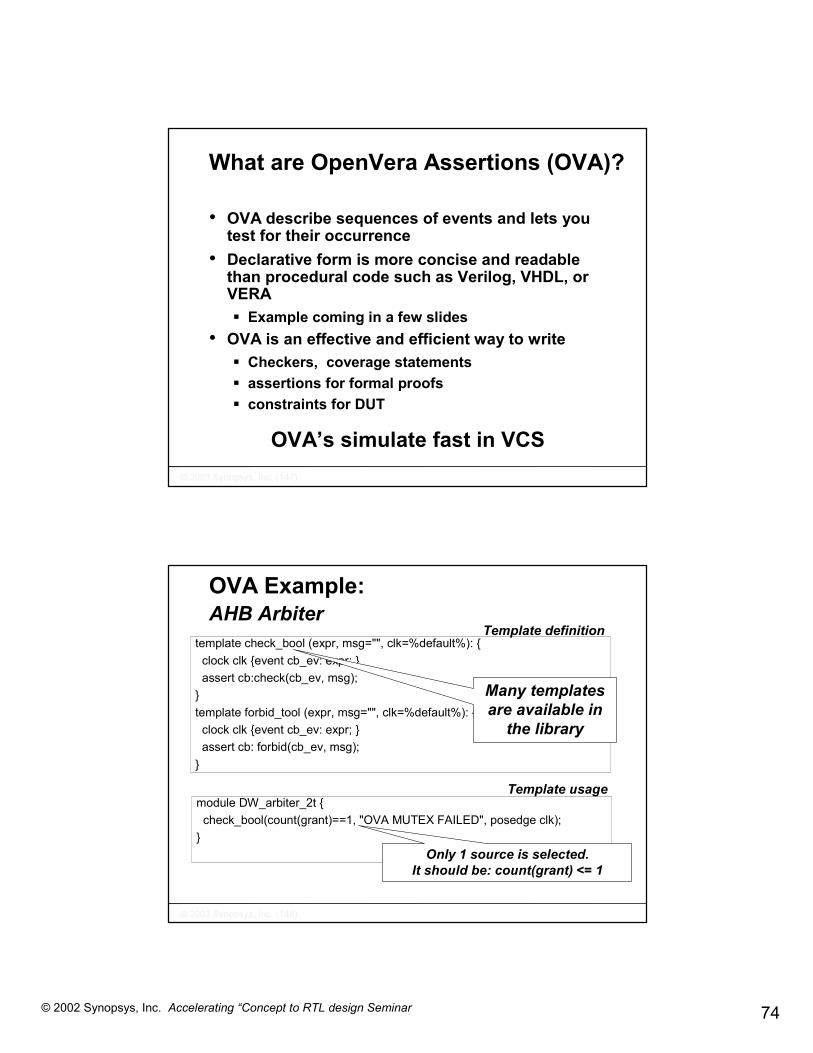
What are OpenVera Assertions (OVA)?
• OVA describe sequences of events and lets you test for their occurrence
• Declarative form is more concise and readable than procedural code such as Verilog, VHDL, or VERA� Example coming in a few slides
• OVA is an effective and efficient way to write� Checkers, coverage statements� assertions for formal proofs� constraints for DUT
OVA’s simulate fast in VCS
��������������� �������������������
OVA Example: AHB Arbiter
template check_bool (expr, msg="", clk=%default%): {clock clk {event cb_ev: expr; }assert cb:check(cb_ev, msg);
}template forbid_tool (expr, msg="", clk=%default%): {
clock clk {event cb_ev: expr; }assert cb: forbid(cb_ev, msg);
}
Many templates are available in
the library
Template definition
module DW_arbiter_2t {check_bool(count(grant)==1, "OVA MUTEX FAILED", posedge clk);
}Only 1 source is selected.
It should be: count(grant) <= 1
Template usage

75© 2002 Synopsys, Inc. Accelerating “Concept to RTL design Seminar
��������������� �������������������
OVA Example:AHB Arbiter
Ova [0]: "../src/test.ova", 12:srs_testbench_test_top.dut.ars_pin1.ars1.DW_ahb_1.U_arb.U_arb2t.ti1_cb:started at 25000 failed at 25000, "OVA MUTEX FAILED"Offending 'count(grant)==1'
Failed, because count(grant) == 0
OVA flow in VCS:1.Instrument & Monitor OVA
- % vcs –ova_debug –ova_report <files.ova>
2.Analyze OVA report- % more simv.vdb/report/ova.report
3.Debug error- % ovadbp
��������������� �������������������
OVA Example:Debug OVA with Virsim
Failed @25,000
Passed @75,000

76© 2002 Synopsys, Inc. Accelerating “Concept to RTL design Seminar
��������������� �������������������
Assertion Summary
• Assertions can incrementally be added to the design blocks� Assertions are automatically reused in chip level
simulation� Can be turned on/off globally/selectively
• Assertions constantly monitor RTL behavior� Requires low overhead in simulation (VCS
supports OVA natively)• Can be used in formal tools
� To proof properties� To generate effective stimulus
��������������� �������������������
SOHO Router: Block level designMeasuring coverage on RTL
• Code coverage metrics (line, condition, FSM)� Built in into VCS
• Functional coverage and dynamic feedback� Directly supported in VERA
• Assertion coverage (OVA)
• Using coverage objects to collect data (with API so info can be used dynamically) + reporting� Persistent coverage database (regression)� Built in into VERA

77© 2002 Synopsys, Inc. Accelerating “Concept to RTL design Seminar
��������������� �������������������
SOHO routerAdding Code Coverage
Coverage metrics flow in VCS:1. Instrument coverage types
- % vcs -cm line+cond+fsm
2. Monitor coverage types- % simv –cm line+cond+fsm
3. Generate/Analyze coverage report- % cmView
4. Test Grading- % cmView
��������������� �������������������
Code Coverage ResultscmView
Lines that are not
exercised
Statistic regarding the block
GUI for modules selection

78© 2002 Synopsys, Inc. Accelerating “Concept to RTL design Seminar
��������������� �������������������
Functional coverage and assertion coverage
• Instrument design with assertions� Link back to spec.
• Define coverage objects to “tally” hit rate
• Create custom reports
ARM 926ATM Block Ethernetblock
Memory
AHB
4x
Arbiter
Coverage object
Report
��������������� �������������������
Agenda
• 1.00 p.m. Introduction and Seminar Overview • 1:10 p.m. Introduce SystemC language• 1:50 p.m. SOC design challenge and SystemC methodology• 2:30 p.m. Tea Break <-----------------------------------------------------• 3:00 p.m. The Concept to RTL flow for the SOHO router
� Today’s design – SOHO Router� Architecture SOC design� SW implementation & debug� Moving from Transaction Level Models to RTL � Reaching golden RTL
• 4:30 p.m. Demo: Multiprocessor ARM design for IP Router• 5p.m. Q&A and Wrap up

79© 2002 Synopsys, Inc. Accelerating “Concept to RTL design Seminar
��������������� �������������������
SOHO router: Chip level design
1. Create top level RTL, connect to testbench through adapters2. Complete top level with remaining (pre-verified ) modules 3. Add remaining drivers.
Test case controller
IP WB
IP WB
Test bench
ATM WB
4x
Protocolstack Ethernet
SystemCTWB
DW IPRTL
Test case controller
MemoryDesign
AHB
4x
ISS Ethernetprocessing
ATM processing3
4Memory
Design
AHB
4x
ISS Ethernetprocessing
ATM processing
USBInterruptcontrollerTimer GPIO UART
UARTGPIO,…
USB
��������������� �������������������
SOHO RouterFull chip verification
• The Verification goal is to check chip level data paths integrity� Assure integrity of RTL for complete chip� Perform limited SW execution
• Focus on reset issues� Perform limited data path simulation
• Focus on corner cases
• Complete regression suite� Requires SystemC/VCS co-simulation

80© 2002 Synopsys, Inc. Accelerating “Concept to RTL design Seminar
��������������� �������������������
SOHO RouterCreating full RTL model
• Designware AMBA RTL bus IP replaces the transaction level models used so far
• ISS wrapped in SystemC is replaced by ISS wrapped in RTL wrapper, or full functional RTL model
• Add additional modules (from Designware) in design AND testbench:� USB controller� IP bus and peripherals
Simulate and build regression suite
��������������� �������������������
Physical designARM-Synopsys Reference Methodology

81© 2002 Synopsys, Inc. Accelerating “Concept to RTL design Seminar
��������������� �������������������
Agenda
• 1.00 p.m. Introduction and Seminar Overview • 1:10 p.m. SOC design challenge and SystemC methodology• 1:40 p.m. Introduce SystemC language• 2:30 p.m. Tea Break <-----------------------------------------------------• 3:00 p.m. The Concept to RTL flow for the SOHO router
� Today’s design – SOHO Router� Architecture SOC design� SW implementation & debug� Moving from Transaction Level Models to RTL � Reaching golden RTL
• 4:30 p.m. Demo: Multiprocessor ARM design for IP Router• 5:00 p.m. Q&A and Wrap up
��������������� �������������������
Concept to RTL SummaryTest case controller
IP WB
IP WB
Design
Test bench
ATM WB
Memory
AHB
4x 4x
Processor model
Protocolstack
Ethernet
Ethernetprocessing
ATM processing
Test case controller ReachArchitecture closure
Test case controller
IP WB
IP WB
ATM processing
Ethernetprocessing
MemoryDesign
Test bench
ATM WB
AHB
4x 4x
ISS
Protocolstack
Ethernet
Test case controllerTest case controller
IP WB
IP WB
MemoryDesign
Test bench
ATM WB
AHB
4x 4x
ISS
Protocolstack
Ethernet
Ethernetprocessing
ATM processing
Test case controller
Software dev.Hardware dev.
Block levelTest case controller
IP WB
IP WB
Test bench
ATM WB
4x
Protocolstack
Ethernet
Test case controller
MemoryDesign
AHB
4x
ISS Ethernetprocessing
ATM processing3
4MemoryDesign
AHB
4x
ISS Ethernetprocessing
ATM processing
USBInterruptcontrollerTimer GPIO UART
UARTGPIO,…
USB
Chip level
82© 2002 Synopsys, Inc. Accelerating “Concept to RTL design Seminar
��������������� �������������������
������������������������������������ ���������� �� �� �� �������� ��������������������������������
��������������������������������������������������������������������������������������������������������
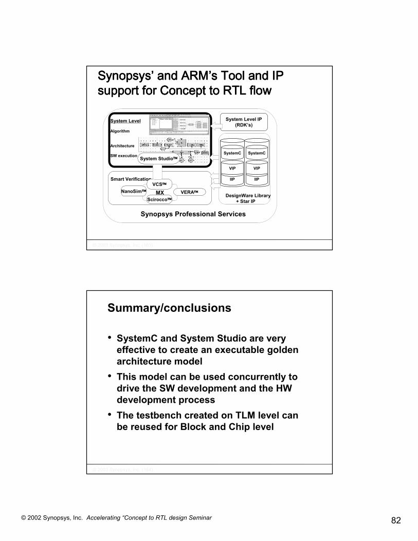
Synopsys Professional Services
Smart Verification
MXVCS
NanoSim VERAScirocco
System Level
Algorithm
Architecture
SW execution System Studio
IIP
VIP
SystemC
IIP
VIP
SystemC
DesignWare Library + Star IP
System Level IP(RDK’s)
��������������� �������������������
Summary/conclusions
• SystemC and System Studio are very effective to create an executable golden architecture model
• This model can be used concurrently to drive the SW development and the HW development process
• The testbench created on TLM level can be reused for Block and Chip level

83© 2002 Synopsys, Inc. Accelerating “Concept to RTL design Seminar
��������������� �������������������