introduction - chegrp5 - homechegrp5.wikispaces.com/file/view/group 5 prelab 4... · web viewthe...
TRANSCRIPT

Fluidized Bed University of Illinois
Fluidized Beds
Picture courtesy of: EPA
High velocity fluid and small solid particle packing are the key features of a fluidized bed reactor. The resulting fluid-particle mixture behaves as a fluid and allows for ample contact between the fluid and the
solid particles. These properties of fluidized bed reactors make them ideal reactors for many types of reactions including catalytic driven reactions. In this lab fluidized bed reactors will be modeled using
sand and silica as the solid packing and air as the high velocity fluid.
1Unit Operations ChE 382 Group 5 Spring 2011 3/14/2011Damo, Duffy, Guerrero, Hsu, Kosak, Qamar, Tyska

Fluidized Bed University of Illinois
Lab Prep Report
Unit Operations II Lab 4
March 14, 2011
Group 5
Andrew Duffy
Daniyal Qamar
Jeff Tyska
Bernard Hsu
Ryan Kosak
Tomi Damo
Alex Guerrero
2Unit Operations ChE 382 Group 5 Spring 2011 3/14/2011Damo, Duffy, Guerrero, Hsu, Kosak, Qamar, Tyska

Fluidized Bed University of Illinois
Contents1. Introduction.........................................................................................................................................4
2. Literature Review/Theory....................................................................................................................5
3. Experimental.....................................................................................................................................13
3.1. Apparatus..................................................................................................................................13
3.2. Materials and Supplies...............................................................................................................16
3.3. Experimental Procedure............................................................................................................18
4. Anticipated Results............................................................................................................................20
5. References.........................................................................................................................................22
6. Appendix I: Job Safety Analysis..........................................................................................................23
3Unit Operations ChE 382 Group 5 Spring 2011 3/14/2011Damo, Duffy, Guerrero, Hsu, Kosak, Qamar, Tyska

Fluidized Bed University of Illinois
1. Introduction
The purpose of this lab is to measure the affects of superficial velocity and particle size on the
pressure drop in a fluidized bed reactor. A fluidized bed reactor consists of a column filled with a solid
packing. High velocity fluid flowing through the column unseats the solid packing causing the
subsequent fluid-particle mixture to then act as a fluid itself (Lab Packet 1). The fluid used can be either
gas or liquid. The most common purpose of a fluidized bed reactor is to ensure that there is ample
contact between the solid particles, reactor fluid, and the reactor walls. This allows for virtually uniform
temperature distribution even when highly exothermic reactions are occurring. Often times the solid
particles are used to catalyze the reaction occurring within the column. In many cases the solid packing
is a support for a catalyst, and fluidization of the particles allows for significant contact between
reactants catalytic particles. The most common uses for fluidized beds are catalytic cracking in the
petroleum industry, as well as coal combustion, catalyst regeneration, solid-gas reactors, ore roasting
and gas adsorption operations (Lab Packet 1).
Though much more complex than a simple packed bed reactor, a fluidized bed reactor also includes
a void fraction for its packing. Because of the void fraction of the packing material, there is a maximum
velocity at which the fluid can move through the reactor without fluidizing the solid packing. The
particles are usually ≤ 500µm in length (Lab Packet 1), however other sources have cited smaller
particles: <300 μm with gases (Sinnott, Towler 667). However, in order for fluidization to occur, the fluid
has to have a minimum velocity in order for the particles to flow easily and rapidly. The observation of
bubbles of fluid passing through the solid packing of the bed is how one would determine that this
minimum velocity has been reached. The bed sits upon a distributor and this allows for an even fluid
4Unit Operations ChE 382 Group 5 Spring 2011 3/14/2011Damo, Duffy, Guerrero, Hsu, Kosak, Qamar, Tyska

Fluidized Bed University of Illinois
distribution. Located at the gas outlet is a disengaging section which prevents solid particles from
flowing out of the system.
Two different fluidized bed columns will be evaluated in this lab. The first will use sand as the solid
packing material. This sand will be of varying grain sizes and air will be the fluid. A second column will
be evaluated with silica as the solid packing material and air as the fluid. The second column will also be
heated. Flow rates and pressure drops throughout the column will be measured and recorded and then
the superficial velocity and minimum fluidization velocity of the system will be found using these
measurements. A relationship between gas velocity and pressure drop can then be established.
2. Literature Review/Theory
Fluidized beds are commonly used in chemical engineering process for multiple purposes, such
as catalytic reactions, solid-gas reactions, coal combustion, roasting ores, drying, and adsorption
operations (McCabe 3). Even though fluidized beds also contain a packing material to give good contact
between the phases, they have several major differences from packed beds. First, the packing is
supported by the up flowing phases and behaves much like a liquid, hence the name. The packing phase
is in constant motion within the fluidized bed. Such a unit is more complex than a simple fixed bed and
has several advantages which can be important in industrial applications: (1) the rapid mixing motion in
the bed gives a high heat transfer rate between the bed and the shell of the unit; thus, heat can be
easily transferred to or away from the bed, (2) the bed unit tends to be quite uniform in concentration
when compared to the non-mixed packed bed; this can be an advantage or a disadvantage for a given
separation or chemical reaction, and (3) the packing can flow out of the unit for separate treatment and
back into the unit (McCabe 145).5
Unit Operations ChE 382 Group 5 Spring 2011 3/14/2011Damo, Duffy, Guerrero, Hsu, Kosak, Qamar, Tyska

Fluidized Bed University of Illinois
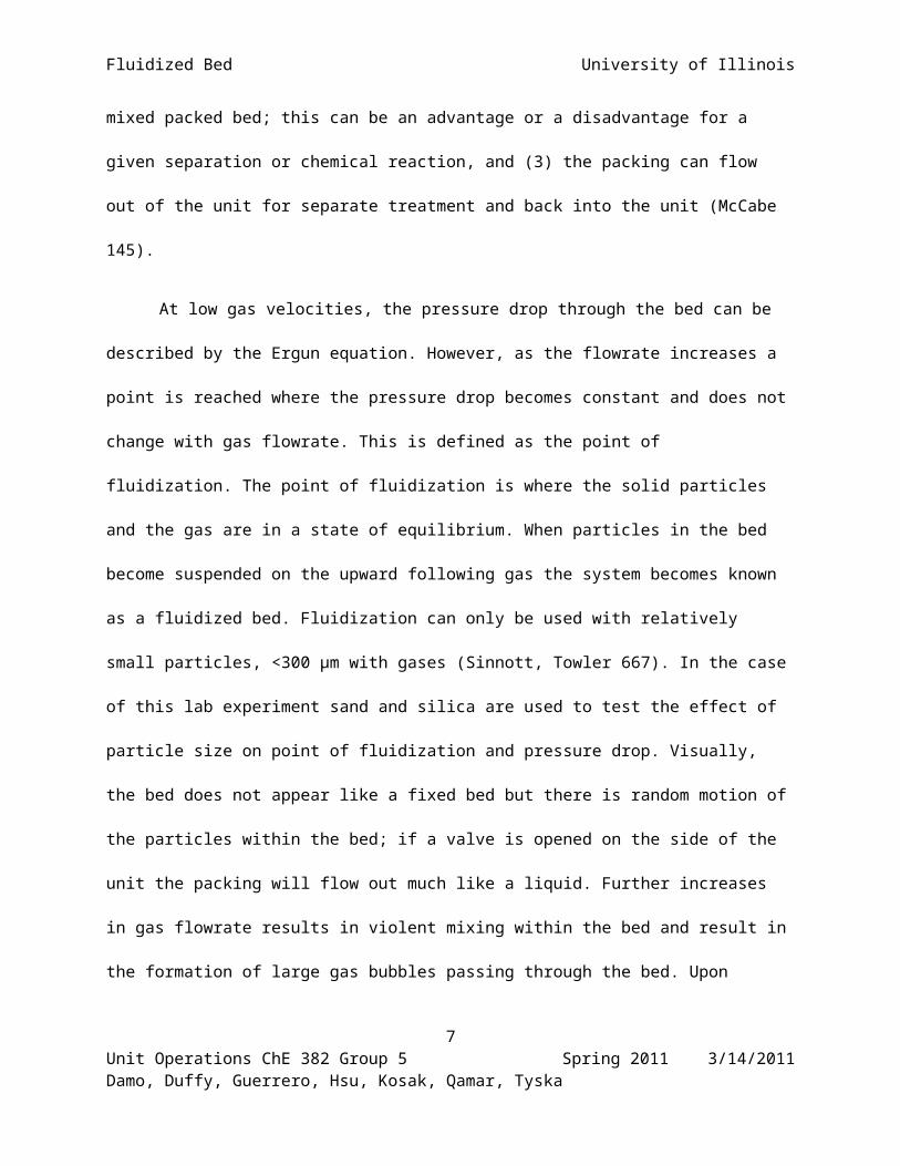
At low gas velocities, the pressure drop through the bed can be described by the Ergun
equation. However, as the flowrate increases a point is reached where the pressure drop becomes
constant and does not change with gas flowrate. This is defined as the point of fluidization. The point of
fluidization is where the solid particles and the gas are in a state of equilibrium. When particles in the
bed become suspended on the upward following gas the system becomes known as a fluidized bed.
Fluidization can only be used with relatively small particles, <300 μm with gases (Sinnott, Towler 667). In
the case of this lab experiment sand and silica are used to test the effect of particle size on point of
fluidization and pressure drop. Visually, the bed does not appear like a fixed bed but there is random
motion of the particles within the bed; if a valve is opened on the side of the unit the packing will flow
out much like a liquid. Further increases in gas flowrate results in violent mixing within the bed and
result in the formation of large gas bubbles passing through the bed. Upon decreasing the gas flowrate,
the pressure drop versus gas flowrate does not exactly follow the previous curve as seen in Figure 1
below. There is a significant hysteresis effect due to the frictional forces in the initial packed bed. The
reason for this path dependence is due to a change in the orientation of the packing particles as they
become looser than before due to the air flowing through the bed; this results in a lower friction factor
and lower pressure drop.
6Unit Operations ChE 382 Group 5 Spring 2011 3/14/2011Damo, Duffy, Guerrero, Hsu, Kosak, Qamar, Tyska
Fluidized Bed University of Illinois
The behavior of the particles based on pressure drop with relation to upward superficial velocity
can be seen in figure 1 below.
Figure 1: Pressure Drop vs. Superficial Velocity (McCabe 3)
In this figure it can be seen as the pressure drop is increased the superficial velocity increases somewhat
exponentially until it reaches a plateau where the minimum fluidization point is. Along the first section
of the graph (area A) the pressure drop can be related to the velocity using the Ergun Equation
(Equation 1). This equation can only be used in this section because of the small pressure drop and
velocity where it is considered a packed bed (Bird, Stewart, Lightfoot 191).
7Unit Operations ChE 382 Group 5 Spring 2011 3/14/2011Damo, Duffy, Guerrero, Hsu, Kosak, Qamar, Tyska

Fluidized Bed University of Illinois
(( P0−PL)∗ρ
G02 )∗(
Dp
L)∗( ε 3
1−ε)=150∗( 1−ε
D pG0
μ )+ 74 (1)
Where:
P0 = initial pressure [Pa]
PL = pressure at the end of the column [Pa]
G0 = mass flux [kg/m2*s]
Dp = particle diameter [m]
L = height of the bed [m]
ε = void fraction [dimensionless]
ρ = density of the particle [kg/m3]
μ = viscosity [kg/s*m]
8Unit Operations ChE 382 Group 5 Spring 2011 3/14/2011Damo, Duffy, Guerrero, Hsu, Kosak, Qamar, Tyska

Fluidized Bed University of Illinois
However, as the velocity and pressure drop increase the Ergun Equation (1) cannot be used in
the determination of fluidized bed values. Figure 2 also shows this relation but with the overall bed
height verses the superficial velocity in the column.
Figure 2: Bed Height vs. Superficial Velocity (McCabe 3)
Point C on both figures is the point of minimum fluidization velocity, V f, and can be calculated by the
following equations. (Note: The small frictional force exerted on the wall was ignored). First the
determination of the upward force by the gas on the bed can be calculated using Equation 2.
Upward forceon the bed=∆ P∗A (2)
Where:
ΔP = pressure drop across the bed [Pa]
A = cross-sectional area of the bed [m2]
9Unit Operations ChE 382 Group 5 Spring 2011 3/14/2011Damo, Duffy, Guerrero, Hsu, Kosak, Qamar, Tyska

Fluidized Bed University of Illinois
Next the volume of the particles can be solved for using Equation 3.
Volume of particles=(1−ε )∗A∗L (3)
Where:
ε = void fraction [dimensionless]
A = cross-sectional area of the bed [m2]
L = height of the bed [m]
From here we can determine the net weight of the particles in the column by using Equation 4.
Net weight of the particles= (1−ε )∗( ρp−ρf )∗A∗L∗g (4)
Where:
A = cross-sectional area of the bed [m2]
L = height of the bed [m]
ε = void fraction [dimensionless]
ρp = density of the particle [kg/m3]
ρ f= density of the fluid [kg/m3]
g = acceleration due to gravity [m/s2]
10Unit Operations ChE 382 Group 5 Spring 2011 3/14/2011Damo, Duffy, Guerrero, Hsu, Kosak, Qamar, Tyska

Fluidized Bed University of Illinois
The theoretical pressure drop can be determined by using Equation 5.
∆ P=(1−ε )∗( ρp−ρf )∗L∗g (5)
Where:
L = height of the bed [m]
ε = void fraction [dimensionless]
ρp = density of the particle [kg/m3]
Typically for a bed with small particles (Dp < 0.1 mm), the flow conditions are such that the Reynolds
number (Re) is relatively small (Re < 10) meaning that the Kozeny-Carmen Equation can be used to find
the velocity of fluidization (Vf) (McCabe 5). This Kozeny-Carmen Equation can be seen as Equation 6.
V f =
( ρp−ρ f )∗g∗Dp2
150∗μ∗ε3
1−ε(6)
Where:
Vf = fluid velocity [m/s]
ε = void fraction [dimensionless]
ρp = density of the particle [kg/m3]
ρ f = density of the fluid (or gas) [kg/m3]
g = acceleration due to gravity [m/s2]
Dp = particle diameter [m]
μ = viscosity [kg/s*m]
11Unit Operations ChE 382 Group 5 Spring 2011 3/14/2011Damo, Duffy, Guerrero, Hsu, Kosak, Qamar, Tyska

Fluidized Bed University of Illinois
When the superficial velocity (Vs) is equal to the fluidized velocity (Vf) this state is known as
“incipient fluidization” (McCabe 5). Next the settling velocity can be determined by restricting the size of
the particle to be small like before so that Stokes Law can be used to calculate this velocity. This can be
seen in Equation 7.
V Settling=( ρp−ρf )∗g∗Dp
2
18∗μ(7)
Where:
Vsettling = settling velocity [m/s]
ρp = density of the particle [kg/m3]
ρ f = density of the fluid (or gas) [kg/m3]
g = acceleration due to gravity [m/s2]
Dp = particle diameter [m]
μ = viscosity [kg/s*m]
Once the velocity of settling and the fluidization velocity are determined a ratio of the two can
be formed relating the void fraction back to both the velocities, which can be seen in Equation 8.
V settling
V f=
253
∗1−ε
ε3(8)
Where:
Vf = superficial velocity [m/s]
Vsettling = settling velocity [m/s]
ε = void fraction [dimensionless]
12Unit Operations ChE 382 Group 5 Spring 2011 3/14/2011Damo, Duffy, Guerrero, Hsu, Kosak, Qamar, Tyska

Fluidized Bed University of Illinois
In cases where the particles a very small it is likely that they may be carried out of the bed system.
Therefore, filters or cyclones must be emplaced to recover these particles at high superficial velocities.
Bubbling fluidization will occur in this experiment because this is strictly a gas-fluidized bed which will be
seen as large pockets of gas moving through the free particles.
3. Experimental
3.1.Apparatus
Equipment Manufacturer Purpose Description
Rotameter Nupro Company To measure air flowrate on column on left
Max flow = 2.2 L / min.
Pressure Meter Omega Engineering Measures pressure of air into rotameter mentioned above
0 – 100 psi
2 Air Valves Crane Company Changes air flowrate into rotameter mentioned above
No. 1. Cranite Disk
2 Half Turn Valves Smith Company Changes air flow rate into fluidized beds
On bottom of each fluidized bed
2 PVC Columns None listed Used as fluidized beds Two are given
2 Tops None Listed Tops to fluidized beds Funnels, so that sand is easy to pour
3 Pipette Bulbs None Listed Used to keep sand from flowing out of the fluidized beds
Normal pipette bulbs
1 U-Tube Manometer Meriam Instruments Used to measure pressure drop in fluidized beds
0 – 25 psi
13Unit Operations ChE 382 Group 5 Spring 2011 3/14/2011Damo, Duffy, Guerrero, Hsu, Kosak, Qamar, Tyska

Fluidized Bed University of Illinois
2- 250 mL Erlenmeyer Flasks
Pyrex Used to collect sand from the fluidized beds
Tubes hooked up to fluidized beds and U-Tube manometer
Plastic Tubes None Listed Used to link up the fluidized beds and U-Tube manometer to the Erlenmeyer flasks
4 in total
Set of Ceramic Spheres None Listed Packing in the bottom of each column
1 set in each column
Thermocouple Fluke Used to show data from thermometers in a fluidized bed
2166A digital thermometer
Thermometers Omega Hooked up to thermocouple, measure temperature in a fluidized bed
3 in total
Heater SE Engineering Used to heat the fluidized bed
In the middle of the apparatus
Rotameter F&P Co Used to measure the air flowrate in a fluidized bed
13.9 CFM maximum
Pressure Gauge None Listed Measures pressure of air to a fluidized bed (on the right)
Made in China, 0 – 200 psi
Valve Apollo To main air supply Yellow
Valve Willerson Corp Used to change the air flowrate into the rotameter on one of the fluidized beds
Near the pressure gauge without a manufacturer name
14Unit Operations ChE 382 Group 5 Spring 2011 3/14/2011Damo, Duffy, Guerrero, Hsu, Kosak, Qamar, Tyska

Fluidized Bed University of Illinois
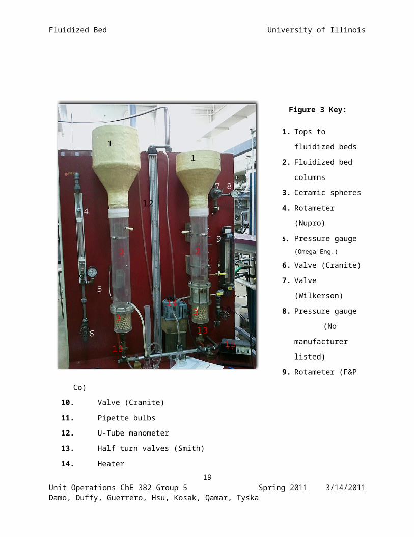
Figure 3 Key:
1. Tops to fluidized beds
2. Fluidized bed columns
3. Ceramic spheres
4. Rotameter (Nupro)
5. Pressure gauge (Omega
Eng.)
6. Valve (Cranite)
7. Valve (Wilkerson)
8. Pressure gauge
(No
manufacturer listed)
9. Rotameter (F&P Co)
10. Valve (Cranite)
11. Pipette bulbs
12. U-Tube manometer
13. Half turn valves (Smith)
14. Heater
15. Thermocouple
Figure 3: Fluidized Bed Lab Station
15Unit Operations ChE 382 Group 5 Spring 2011 3/14/2011Damo, Duffy, Guerrero, Hsu, Kosak, Qamar, Tyska

Fluidized Bed University of Illinois
3.2.Materials and Supplies
Equipment Manufacturer Purpose Description
1 Scooper None listed Used to scoop out sand
Made of plastic
1 Yardstick None listed Used to measure the height of the sand
Also used for other labs
Air None Used to create the fluidized bed
From the main compressed air line
Water None Used to help calculate the density of sand
From a faucet
Wet-Dry Vac Dayton For vacuuming up loose sand and silica
120 V, 60 Hz
Sieves Us Standard Sieve Series Used to separate the sand into different size distributions
Multiple sieves, 4750 – 28 microns
Graduated Cylinder 250 mL Used to store sand and water in for the density calculations
TC/TD at 20 degrees Celsius
Beaker Pyrex Used to store sand in for the density calculations
40 mL
Funnel None listed Used to funnel sand into beaker and graduated cylinder
1 in total
Sea Sand Fischer Scientific For use as packing in fluidized bed
Normal sand, various particle sizes
Silica Fischer Scientific For use as packing in fluidized bed
Looks like crushed quartz, similar particle sizes
16Unit Operations ChE 382 Group 5 Spring 2011 3/14/2011Damo, Duffy, Guerrero, Hsu, Kosak, Qamar, Tyska

Fluidized Bed University of Illinois
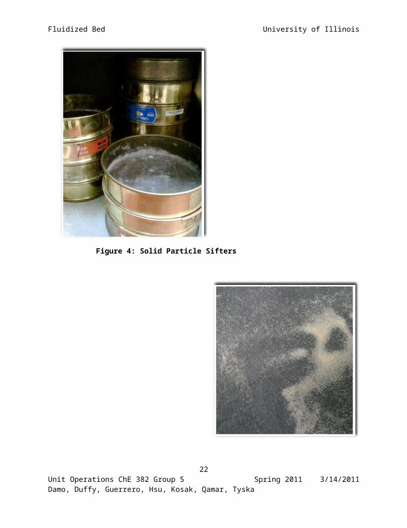
Figure 4: Solid Particle Sifters
17Unit Operations ChE 382 Group 5 Spring 2011 3/14/2011Damo, Duffy, Guerrero, Hsu, Kosak, Qamar, Tyska

Fluidized Bed University of Illinois
Figure 5: Solid Particle (sand)
3.3.Experimental Procedure
Start Up
1. Check that the apparatus and all required materials are present and in working order. Clean out
columns (2) if not already clean.
2. Clean, by taping, and stack the sieve trays in descending order of grain diameter. Set up a
container to catch the fly off sand
3. Record the diameter range of the two decided sand samples as well as the silica.
4. Using a 100 ml graduated cylinder, add 25 ml of sand sample.
5. Add an equal amount of water to the graduated cylinder.
6. Allow sufficient time to pass for the water to penetrate the sand layer then measure the final
volume.
7. Use these measurements to calculate the void fraction. Repeater for each sample.
18Unit Operations ChE 382 Group 5 Spring 2011 3/14/2011Damo, Duffy, Guerrero, Hsu, Kosak, Qamar, Tyska
Fluidized Bed University of Illinois
Sand Column Procedure
8. Load the first sand sample into the left column (2). Add roughly 10 cm of sand to the column.
Tap the column to even out the sand and accurately measure the sand’s height.
9. Make sure all valves are in the proper starting position
10. Fully open the valve at the base of the column (13), and then slowly open the flow meter valve
(5) to allow air in.
11. For each increment of change in the air flow record: the air flow rate, the pressure drop, height
of the packed bed also any notable observations with the packed bed.
12. Keep incrementally increasing the flow rate until the maximum is achieved. Maximum is noted
by a plateau of pressure drop with increasing air flow.
13. Repeat recording for decreases in airflow.
14. Remove all the sand with the Shop-Vac and repeat steps 8 to 13 with the second sample of
sand. Empty out the sand into separate container so not to mix it with the silica later on.
Silica Column Procedure
15. Load silica in the right column (2). Add enough silica to cover the top thermal sensor by 1.5
inches
16. Open the air valve at the bottom of the right column (13) (have the left one closed) then slowly
open the flow meter valve to let in air.
17. For each incremental change in air flow record: the air flow rate, the pressure drop, the height
of the packed bed and any observations.
18. Once the maximum is reached record it.
19. Start to slowly decrease the air flow rate and record the corresponding measurements.
19Unit Operations ChE 382 Group 5 Spring 2011 3/14/2011Damo, Duffy, Guerrero, Hsu, Kosak, Qamar, Tyska

Fluidized Bed University of Illinois
20. Turn of the air and the turn on the heater (14). Wait till packed material reaches steady state
temperature.
21. With the heated bed repeat steps 16 to 19. Along with the standard measurements also record
both top and bottom temperatures.
Shut Down and Clean Up
22. Turn of air supply (6), heater (14) and digital thermometer (15).
23. Remove funnels (1) for the top of both columns and use Shop-Vac to clean the column and
bench area.
24. Organize sieve trays and place inside the cabinet.
4. Anticipated Results
The purpose of this lab experiment is to use sand and silica to test the effect of particle
size on point of fluidization and pressure drop. The point of fluidization is reached when the
gas/liquid velocity is sufficient enough to lift the bed and cause it to behave like a fluid. As the
air velocity going through the bed is increased the pressure drop is noted. This pressure varies
according to the velocity of air flowing through the column and how tightly the bed is packed
(the void fraction).
The pressure vs. velocity graph should look very similar to figure 1 on page 7. As the
columns are packed and the air is let in, the pressure drop will start to increase. As more force
will be required to loosen the bed and get the bed to start moving, this pressure drop will keep
rising. The bed height will appear to stay constant as the pressure drop rises. Eventually the
pressure drop will stop increasing and the point of minimum fluidization velocity will be
20Unit Operations ChE 382 Group 5 Spring 2011 3/14/2011Damo, Duffy, Guerrero, Hsu, Kosak, Qamar, Tyska

Fluidized Bed University of Illinois
reached. At this point the bed has become fluidized and the sand or silica particles are loosened
and flying around in the column. The bed height will appear to start increasing and at this point
the energy needed to lift the bed particles is provided by the air velocity and increasing the
height of the bed does not influence the pressure drop anymore. As the air velocity is increased it
will reach a point when the sand or silica particles will start escaping the column, this velocity is
called the settling velocity and beyond this point the particles will exit the column with the air.
Just as in figure 1 on page 7 as the velocity of air will be decreased the pressure drop will take a
different path. The orientation of every particle will be a lot different than it was before the
minimum fluidization velocity was reached; the bed was a lot tightly packed and not loosened
yet. Since all the particles rearrange to a loosened configuration the pressure drop as the velocity
is decreased will be less as well.
In addition to the air velocity affect on the pressure drop, the particle grain size will also
affect the pressure drop. The size of the particles determines the void fraction which affects the
superficial velocity and the pressure drop as well. The finer the grain size is the lower the void
fraction is since the bed will be tightly packed. Referring to equation 6 it is clearly evident that as
the particle size increases (increase in void fraction, the diameter, and the density) the superficial
velocity increases as well. This increase in velocity will give rise to a higher pressure drop as
well. Since the diameter, the density, and the void fraction are all going to be bigger for larger
particles it can be concluded that a bigger value of the minimum fluidization velocity will be
seen for the bigger particles. However the finer grains will result in a larger bed height since
finer grains are easier to rise as the same pressure drop is applied.
The silica bed will be heated so an effect of temperature will be seen here as well. As the
air will expand upon heating the pressure drop will appear to increase as well. From equations 5
21Unit Operations ChE 382 Group 5 Spring 2011 3/14/2011Damo, Duffy, Guerrero, Hsu, Kosak, Qamar, Tyska
Fluidized Bed University of Illinois
and 6 it can be seen that as the density of the fluid decreases (expanded air, same mass bigger
volume) the velocity and the pressure drop both increase. The bed height will appear to be larger
as well since the air occupies more volume when heated.
5. References
Bird, R. Byron, Warren E. Stewart, and Edwin N. Lightfoot. Transport Phenomena. New York: J. Wiley, 2007. Print.
"Fluidized Beds." University of Illinois at Chicago - UIC. Web. 25 Jan. 2010. <http://www.uic.edu/depts/chme/UnitOps/che381-2005f-frame.html>.
Sinnott, Ray, and Gavin Towler. Chemical Engineering Design. Amsterdam: Elsevier, 2009. Print.
W.E. McCabe, J.C. Smith, and P. Harriott 2001. Unit Operations of Chemical Engineering, McGraw Hill, New York.
22Unit Operations ChE 382 Group 5 Spring 2011 3/14/2011Damo, Duffy, Guerrero, Hsu, Kosak, Qamar, Tyska

Fluidized Bed University of Illinois
6. Appendix I: Job Safety Analysis
What is the purpose of this experiment?
The purpose of this experiment is to determine the gas pressure drop across a bed of particles as
a function of the gas velocity. The fluidization behavior of a bed of small particles will be
studied.
What are the hazards associated with the experiment?
The spilling of sand and silica on the floor, which will occur during operation of the column and
during the sifting of the sand in order to obtain the right particle size range, makes for a slippery
work environment. Compressed air is used to fluidize the bed. Since there is air passing through
small sand and silica particles, it is possible that these particles could enter the eye, nose and/or
mouth. A heater adjacent to the fluidized bed apparatus is used and could possibly expel
exuberant amounts of heat and burn the operator.
How will the experiment be conducted in a safe manner?
A vacuum is included with the station to maintain a clean working and walking area when sand
and silica are being used. Eye protection will be worn so that sand and silica particles do not
enter the operator’s eyes. Care should be taken not to inhale either of these particles and hands
will be washed after working with the silica.
23Unit Operations ChE 382 Group 5 Spring 2011 3/14/2011Damo, Duffy, Guerrero, Hsu, Kosak, Qamar, Tyska

Fluidized Bed University of Illinois
What safety controls are in place?
The air inlet regulator has an internal diaphragm that will maintain constant inlet pressure of 40
psig. Should the pressure increase erratically, the regulator valve will relieve the pressure to
maintain the inlet pressure. The vacuum cleaner has a filter adapter attached which prevents
excessive dust accumulation when cleaning up the area. The columns are fitted with a
disengaging section to prevent solid particles from leaving the system.
Describe safe and unsafe ranges of operations.
In order to prevent blowing sand or silica out the top of the column, operate at a superficial
velocity below the settling velocity. Carefully controlling increments air flowing through the
column will prevent the discharge of the bed out the top of the column. Silica column cannot be
heated to temperatures greater than 110°F. Should the Plexiglas reach temperatures of 265ºF,
then it will melt.
I have read relevant background material for the Unit Operations Laboratory entitled:
“Fluidized Beds” and understand the hazards associated with conducting this experiment. I have
planned out my experimental work in accordance to standards and acceptable safety practices
and will conduct all of my experimental work in a careful and safe manner. I will also be aware
of my surroundings, my group members, and other lab students, and will look out for their safety
as well.
24Unit Operations ChE 382 Group 5 Spring 2011 3/14/2011Damo, Duffy, Guerrero, Hsu, Kosak, Qamar, Tyska
Fluidized Bed University of Illinois
I have read relevant background material for the Unit Operations Laboratory entitled:
“Fluidized Bed” and understand the hazards associated with conducting this experiment. I have
planned out my experimental work in accordance to standards and acceptable safety practices
and will conduct all of my experimental work in a careful and safe manner. I will also be aware
of my surroundings, my group members, and other lab students, and will look out for their safety
as well.
25Unit Operations ChE 382 Group 5 Spring 2011 3/14/2011Damo, Duffy, Guerrero, Hsu, Kosak, Qamar, Tyska

Fluidized Bed University of Illinois
Electronic Signatures:
Bernard Hsu
Daniya l Qamar
Jeff Tyska
Alex Guerrero
Tomi Damo
Ryan Kosak
Andrew Duffy
26Unit Operations ChE 382 Group 5 Spring 2011 3/14/2011Damo, Duffy, Guerrero, Hsu, Kosak, Qamar, Tyska