intravenous video arteriography of the intracranial …right extraocular muscle dysfunction, it was...
TRANSCRIPT

Charles M. Strother 1 Joseph F. Sackett1
Andrew B. Crummy1 Charles A. Mistretta 1
David l. Ergun 1 Chorng C. Shaw 1
Robert A. Kruger 1, 2
Thomas A. Duff3
Lincoln F. Ramirez3
William D. Turnipseed3, 4
Received November 17, 1980; accepted January 7, 1981
'Department of Radiology, University of Wisconsin, Clinical Science Center, 600 Highland Ave., Madison, WI 53792. Address reprint requests to C. M. Strother.
' Present address: Department of Radiology, University of Utah Medical Center, Salt Lake City, UT 84132.
3Department of Surgery, University of Wisconsin, Clinical Science Center, Madison, WI 53792.
' Present address: Department of Surgery, William S. Middleton Veterans Administration Hospital, Madison, WI 53792.
AJNR 2:215-218, May/ June 1981 0195-6108/ 81 / 0203-0215 $00.00 © American Roentgen Ray Society
Intravenous Video Arteriography of the Intracranial Vasculature: Early Experience
215
A computerized fluoroscopic apparatus developed by members of the University of Wisconsin Medical Physics Section was used for 12 months to perform intravenous video arteriography. In previous papers, the apparatus was described and its use was illustrated for performing time subtraction intravenous video arteriography of the extracranial carotid arteries, the arteries of the abdomen and extremities, as well as angiocardiography. In this report, the use and current limitations of this technique for evaluation of the intracranial vasculature are described and illustrated.
Until recently, it has been impossible to achieve satisfactory visualization of the intracranial vasculature following intravenous administration of contrast medium [1 - 3]. New digital electronic techniques permit processing of the video signal from a conventional image-intensified fluoroscopic system for isolation of the small iodine signal produced after the intravenous injection of contrast medium. Logarithmic amplification combined with subtraction can increase the ratio of the iodine signal to the signal variation of normal anatomic structures by a factor of greater than 100. This type of image processing ensures uniform visualization of the iodine as it passes from the heart to the arteries of the neck and into the cranial vault . Our experience in demonstrating the intracranial arteries with this new method is described.
Materials and Methods
For examination of intracranial vascular structures, mask mode rad iography is employed. An image is obtained before arrival of the contrast med ium and is stored in one of two memories . As the iodinated contrast medium passes through the vasculature of th e skull and brain, serial images are collected in a second memory, subtracted from the mask, and are then stored on a video disk and video tape. For examination of the intracranial vasculature , the exposure factors are 300 mA, '/ ' 5 sec at 65-85 kVp . Images are generated at the rate of 1 /sec. Further details of this imag ing sequence have been reported previously [4-6] .
Since our initial clinical reports [7, 8], our technique for intravenous inject ion of con trast medium has been modified. Previously, we injected 40-60 ml of contrast med ium at the rate of 12-14 ml / sec through a 16-gauge, 5-cm-long Angiocath inserted into a basilic vein. While using this technique for over 300 intravenous video arteriog rams, we encountered three instances of extravasation of the con trast med ium at the injection site. To eliminate this potential complication and to obtain a more consistent contrast bolus, we now use a percutaneously introduced 5 French catheter with an end hole and fou r side holes, positioning the tip in the cen tral innominate vein or superior vena cava .
For examinat ion of the petrous, cavernous, and supraclinoid parts of th e internal carotid artery, a project ion which positions the top of the petrous bones in the center of the orbit seems to provide the best results. Such a prOjection is also satisfactory for visualization of the distal segments of the vertebral arteries and of the major part of the basi lar artery . Because our resolution is cu rrent ly limited by focal spot size (over 1.1 mm during the exposures), and a large magn ificat ion factor (greater than 1.5) caused by an under-the-
216 STROTHER ET AL. AJNR :2 , May / June 1981
table tube position , we have not made a systematic effort to design projec tions for visualization of arteries above the c irc le of Willi s. Nonetheless, image quality is sufficient to allow, in many instances, evalu ation of the proximal parts of the middle and anterior cerebral arteries . These arteries are well seen in the projection described for examination of the intracranial segments of th e internal carotid artery .
Results
Because development and improvement of our computerized f luoroscopic apparatus is still ongoing, we have not felt it appropriate to carry out a study to compare intravenous video arteriograms with standard techniques. At this time, definitive study of the intracranial vasculature usually requires conventional intraarterial catheter techniques. Nonetheless, in some c ircumstances , the image quality with intravenous video arteriography is sufficient to allow decisions regardi ng diagnosis and management.
Representative Case Reports
Case 1
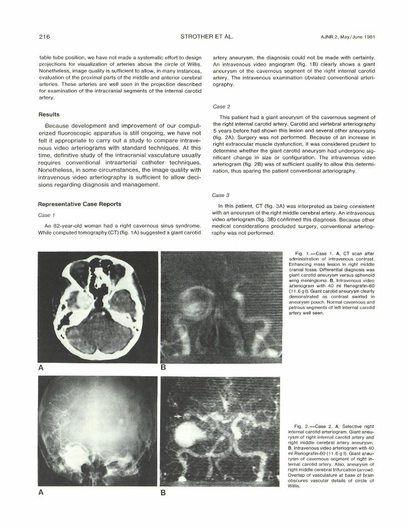
An 82-year-old woman had a right cavernous sinus syndrome. While computed tomography (CT) (fig. 1 A) suggested a giant carotid
A 8
artery aneu rysm, the diagnosis could not be made with certa inty. An intravenous video angiogram (fig. 1 B) clearly shows a giant aneurysm of the cavernous segment of the right internal carotid artery. The intravenous examination obviated conventional arteriography.
Case 2
This patient had a giant aneurysm of the cavernous segment of the right internal carotid artery. Carotid and vertebral arteriography 5 years before had shown this lesion and several other aneurysms (fig . 2A). Surgery was not performed. Because of an increase in right extraocular muscle dysfunction , it was considered prudent to determine whether the giant carotid aneurysm had undergone significant change in size or configurat ion . The intravenous video arteriog ram (fig . 2B) was of suffic ient quality to allow this determinat ion , thus sparing the patient conventional arteriography .
Case 3
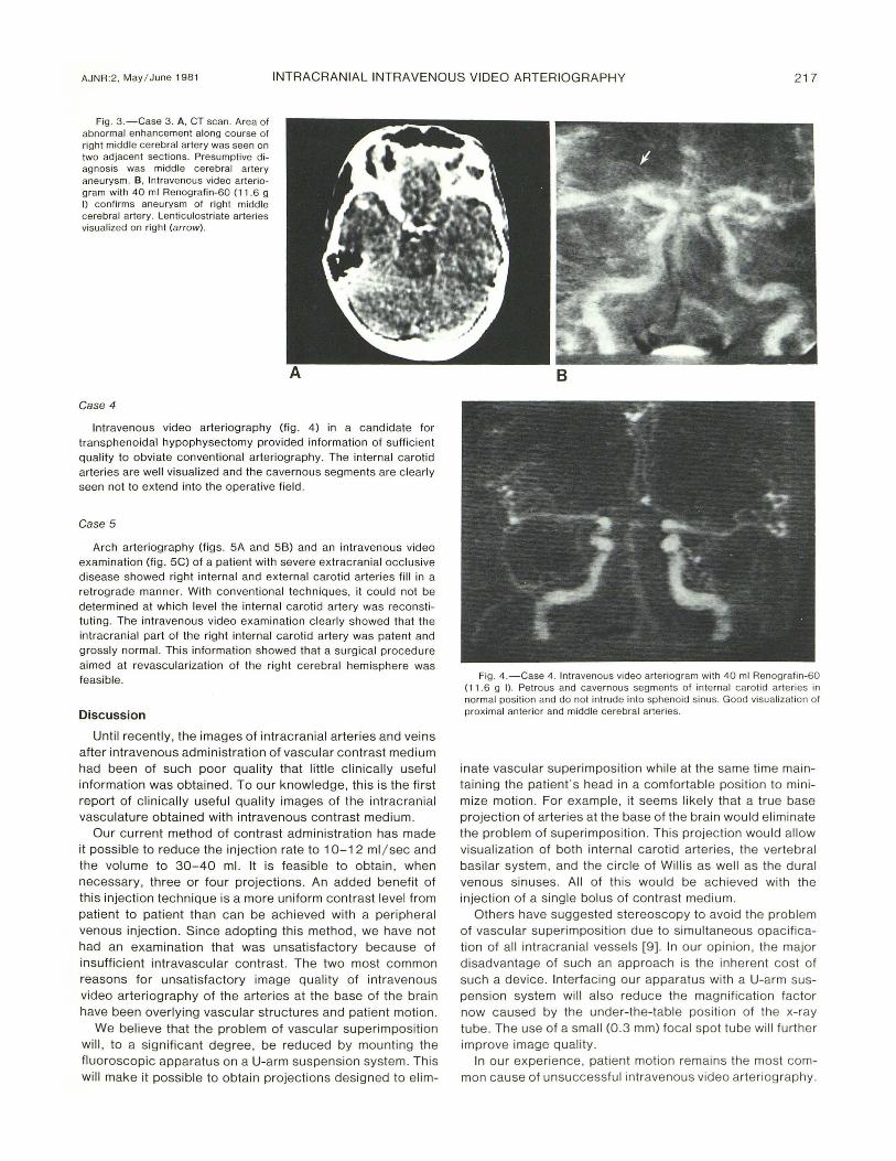
In this patient , CT (fig . 3 A) was interpreted as being consistent with an aneurysm of the right middle cerebral artery. An intravenous video arteriogram (fig. 3B) confirmed this diagnosis. Because other medical considerat ions precluded su rgery, conventional arteriography was not performed .
Fig . 1 .-Case 1. A, CT scan after admin istration of intravenous contrast. Enhancing mass lesion in right middle cranial fossa. Differential d iagnosis was giant carotid aneurysm versus sphenoid wing meningioma. B, Intravenous video arteriogram with 40 ml Renografin-60 (11 .6 g I) . Giant carotid aneurysm c learly demonstrated as contrast swirled in aneurysm pouch. Normal cavernous and petrous segments of left internal carotid artery well seen.
Fig . 2.-Case 2. A , Selective right intern al carotid arteriogram. Giant aneurysm of right internal carotid artery and right middle cerebral artery aneurysm. B, Intravenous video arteriogram with 40 ml Renografin-60 (11 .6 g I) . Giant aneurysm of cavernous segment of right internal carotid artery. Also, aneurysm of right middle cerebral trifurcation (arrow). Overlap of vasculature at base of brain obscures vascu lar details of c irc le of Wi ll is.
AJNR:2, May / June 198 1 INTRACRANIAL INTRAVENOUS VIDEO ARTERIOGRAPHY 217
Fig . 3. -Case 3. A , CT scan. Area of abnorm al enhancement along course of right middle cerebral artery was seen on two adjacent sections. Presumptive diagnosis was middle cerebral artery aneurysm. B, Intravenous video arteriogram with 40 ml Renografin-60 (11 .6 g I) confirms aneurysm of right middle cerebral artery. Lenticulostriate arteries visualized on right (arrow).
Case 4
Intravenous video arteriography (fig . 4) in a candidate for transphenoidal hypophysectomy provided information of sufficient quality to obviate conventional arteriography . The internal carotid arteries are well visualized and the cavernous segments are clearly seen not to extend into the operative field .
Case 5
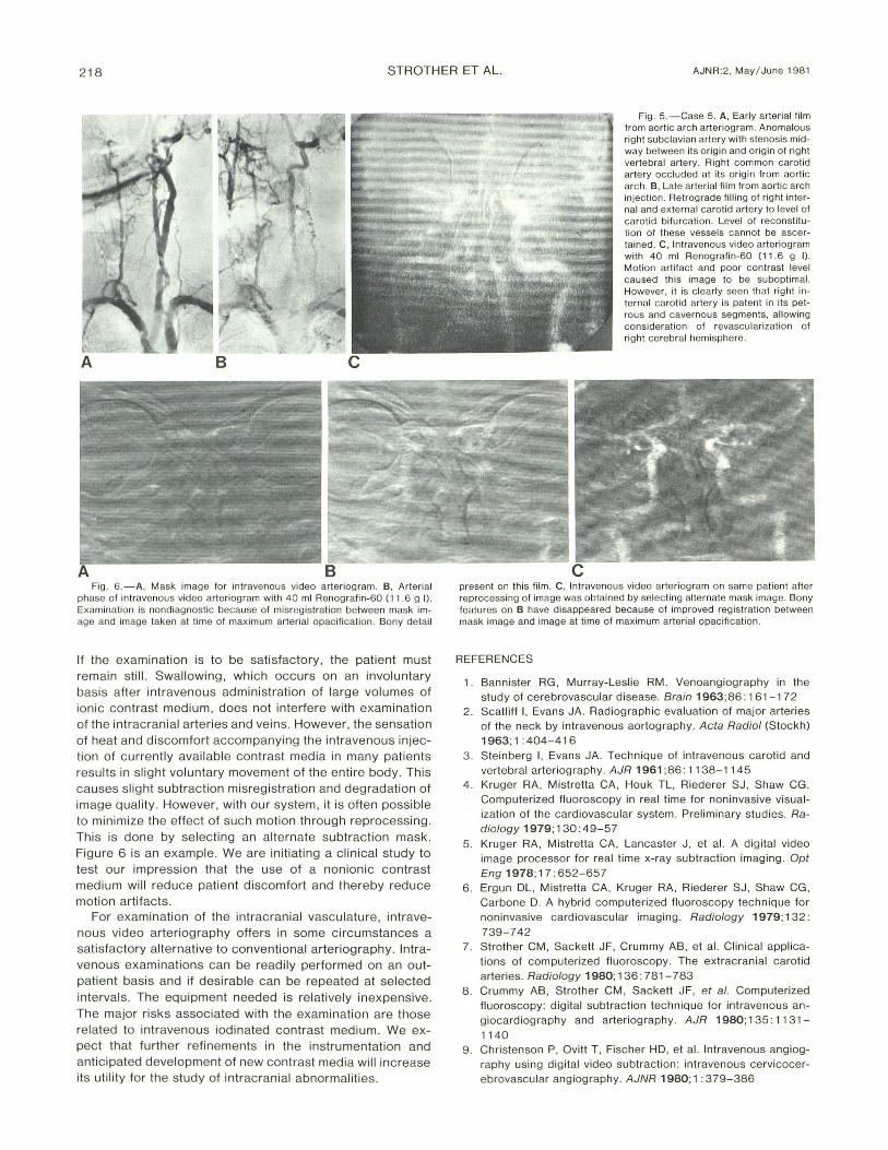
Arch arteriog raphy (figs. 5A and 58) and an intravenous video examination (fig. 5C) of a patient with severe extracranial occlusive disease showed right internal and external carotid arteries fill in a retrograde manner. With conventional techniques , it could not be determined at which level the internal carotid artery was reconstitut ing . The intravenous video examination c learly showed that the intracranial part of the right internal carotid artery was patent and grossly normal. This information showed th at a surgical procedure aimed at revascularization of the right cerebral hemisphere was feasib le.
Discussion
Until recently , the images of intracranial arteries and veins after intravenous administration of vascu lar contrast medium had been of such poor quality that little clinically useful information was obtained. To our knowledge, th is is the first report of clinicall y useful quali ty images of the intracran ial vasculature obtained with intravenous contrast medium.
Our current method of contrast administration has made it possible to reduce the injection rate to 10-12 ml / sec and the volume to 30- 40 ml. It is feasible to obtain, when necessary, three or four projections . An added benefit of this injection techn ique is a more uniform contrast level from patient to patient than can be achieved with a peripheral venous injection. Since adopting this method , we have not had an examination that was unsatisfactory because of insufficient intravascular contrast. The two most common reasons for unsatisfactory image quality of intravenous video arteriography of the arteries at the base of the brain have been overlying vascular structures and patient motion .
We believe that the problem of vascular superimposition will, to a significant degree, be reduced by mounting the fluoroscopic apparatus on a U-arm suspension system . This will make it possible to obtain projections designed to elim-
Fig. 4 .-Case 4. Intravenous video arteriogram with 40 ml Renografin-60 (11 .6 g I) . Pet rous and cavernous seg ments of intern al carot id arteries in normal posi tion and do not intrude into sphenoid sinus. Good visua lizat ion of proximal anteri or and middle cerebral arteries.
inate vascular superimposition whil e at the same time maintaining the patient's head in a comfortab le position to minimize motion . For example, it seems likely that a true base projection of arteries at the base of the brain would eliminate the problem of superimposition . Th is projection would al low visualization of both internal carotid arteries , the vertebral basilar system, and the c irc le of Will is as well as the dural venous sinuses. All of this would be ach ieved with the injection of a single bolus of contrast medium .
Others have suggested stereoscopy to avo id the problem of vascular superimposition due to simu ltaneous opac ification of all intracranial vessels [9]. In ou r op inion, the major disadvantage of such an approach is the inherent cost of such a device. Interfac ing ou r apparatus with a U-arm suspension system will also reduce the mag nification factor now caused by the under-the-table position of the x-ray tube. The use of a small (0 .3 mm) focal spot tube will furth er improve image quality.
In our experience, patient motion remains the most common cause of unsuccessful intravenous video arteriography.
218 STROTHER ET AL. AJNR:2, May / June 1981
A B c
Fig . 6. -A, Mask image for intravenous video arteriogram . B. Arterial phase of intravenous video arteriogram with 40 ml Renografin-60 (11 .6 g I) .
Examination is nondiagnosti c because of misregistration between mask image and image taken at time o f max imum arterial opac ification . Bony detail
If the examination is to be satisfactory, the patient must remain still. Swallowing, which occurs on an involuntary basis after intravenous administration of large volumes of ionic contrast medium, does not interfere with examination of the intracranial arteries and veins . However, the sensation of heat and d iscomfort accompanying the intravenous injection of currently available contrast media in many patients results in slight voluntary movement of the entire body. This causes slight subtraction misregistration and degradation of image quality. However, with our system, it is often possible to minimize the effect of such motion through reprocessing. This is done by se lecting an alternate subtraction mask. Figure 6 is an example. We are initiating a clin ical study to test our impression that the use of a nonionic contrast medium will reduce patient discomfort and thereby reduce motion artifacts.
For examination of the intracranial vasculature, intravenous video arteriography offers in some circumstances a satisfactory alternative to conventional arteriography. Intravenous examinations can be readi ly performed on an outpatient basis and if desirable can be repeated at selected intervals . The equ ipment needed is relatively inexpensive. The major risks associated with the examination are those related to intravenous iodinated contrast medium. We expect that further refinements in the instrumentation and anticipated development of new contrast media wi ll increase its utility for the study of intracranial abnormalities.
Fig. 5.-Case 5. A, Early arterial film from aortic arch arteriogram . Anomalous right subclavian artery with stenosi s midway between its origin and origin of right vertebral artery . Right common carotid artery occ luded at its orig in from aortic arch. B , Late arterial fi lm from aortic arch injection . Retrograde fi lling of right internal and extern al carotid artery to level of carotid bifurcation. Level of reconstitution of these vessels cannot be ascertained . C, Intravenous video arteriogram with 40 ml Renografin-60 (11 .6 g I). Motion artifac t and poor contrast level caused this image to be subopt imal. However, it is c learly seen that right internal carotid artery is patent in its petrous and cavernous segments, allowing consideration of revascularization of right cerebral hemisphere.
present on this film . C. Intravenous video arteriogram on same patient after reprocessing of image was obtained by selecting alternate mask image. Bony features on B have disappeared because o f improved reg istration between mask image and image at time of maximum arterial opacification .
REFERENCES
1. Bannister RG, Murray-Leslie RM . Venoangiography in the study of cerebrovascu lar disease. Brain 1963;86: 161 -1 72
2 . Scatliff I, Evans JA. Radiographic evaluation of major arteries of the neck by intravenous aortography. Acta Radiol (Stockh) 1963; 1 : 404-416
3 . Steinberg I, Evans JA. Technique of intravenous carotid and vertebral arteriography. AJR 1961 ;86 : 11 38-1145
4 . Kruger RA , Mistretta CA, Houk TL, Riederer SJ , Shaw CG. Computerized fluoroscopy in real time for noninvasive visualization of the cardiovascu lar system . Preliminary stud ies. Radiology 1979; 130: 49-57
5. Kruger RA , Mistretta CA , Lancaster J , et al. A digital video image processor for real time x-ray subtract ion imaging . Opt Eng 1978; 17 : 652-657
6. Ergun DL, Mistretta CA, Kruger RA , Riederer SJ, Shaw CG, Carbone D. A hybrid computerized fluoroscopy technique for noninvasive card iovascu lar imaging. Radiology 1979; 132: 739-742
7. Strother CM, Sackett JF, Crummy AB, et al. Clinical applications of computerized fluoroscopy. The extracranial carotid arteries. Radiology 1980; 136: 781-783
8 . Crummy AB , Strother CM, Sackett JF, et al. Computerized fluoroscopy: digital subtraction technique for intravenous angiocardiography and arteriog raphy . AJR 1980; 135 : 11 31-
1140 9. Christenson P, Ovitt T, Fischer HD, et al. Intravenous angiog
raphy using digital video subtraction : intravenous cerv icocerebrovascular angiography . AJNR 1980; 1 : 379-386