interpolators and interpolation · spectrum of interpolator and periodic spectrum of zero-packed...
TRANSCRIPT

InterpolatorsAnd Interpolation
1

Applications
• Fixed Up-Sampler Interpolators• Fixed Down-Sample Filters• Reduced Cost Filtering When Large
Ratio of Sample Rate to Bandwidth• Timing Recovery Re-Sampling of Time
Series• Timing Recovery Re-Sampling of
Matched Filter• Clock Domain Alignment
2

Spectrum of Interpolator andPeriodic Spectrum of
Zero-Packed Shaping Filter
-30 -20 -10 0 10 20 30-80
-60
-40
-20
0
Spectrum of Shaping Filter and 1-to-32 Interpolating Filter
Normalized Frequency
Gai
n (d
B)
-8 -6 -4 -2 0 2 4 6 8-80
-60
-40
-20
0
Zoom to Spectrum
Normalized Frequency
Gai
n (d
B)
3

Spectrum of 1-to-32 Interpolated Shaping Filter
-30 -20 -10 0 10 20 30-80
-60
-40
-20
0
Spectrum of Interpolated Shaping Filter
Normalized Frequency
Gai
n (d
B)
-8 -6 -4 -2 0 2 4 6 8-80
-60
-40
-20
0
Zoom to Spectrum
Normalized Frequency
Gai
n (d
B)
4

Polyphase Partition of M-PathResampling Filter
H (Z )
H (Z )
H (Z )
H (Z )
0
1
2
M-1
x(n) y(m)
N/M= 4
....
....
5

Efficient Hardware Implementation of 1-to-M Polyphase Interpolator
N/M= 4
H (Z ) r
......
x(n) y(m )
h(0+ nM)
h(1+ nM)
h(2+ nM)
h(M-1+ nM)
6

Interpolation Options
Initial Sample Grid,
Unit distance
Between Samples
Same Rate Samp le Grid,
Unit Distance
Between Sam ples
Higher Rate Sam ple Grid ,
Less Than Unit Distance
Between Samp les
Lower Rate Sam ple Grid,
More Than Unit Distance
Between Samp les
Interpola ted Samp le PositionsInitial Sample Positions
7

M-Path, 1-to-M/Q Interpolator
H (Z )
H (Z )
H (Z )
H (Z )
0
1
2
M-1
x(n)y(m )
N/M= 4
....
.... Q:1
Q:11:Mx(n) y(m)
H(Z)
Polyphase Filter
8

5/3, Rational Ratio Re-Sampling
3-to-1
phs(0)
phs(1)
phs(2)
phs(3)
phs(4)
x(n)
y (m)= x(n+ k/5)5
y(m)= x(n+ 3k/5)
n n+ 1 n+ 2 n+ 3
0 1 2 3 4 0 1 2 3 4 0 1 2 3 4 0 1 2 3 4
x x x x xx x x xx x x x
In Out
n 0,3
n+ 1 1,4
n+ 2 2
K(m+1)=[k(m)+3] modulo(5)
9

Rational Ratio Interpolation. Example; up 8, down 3
n+ 1
m+ 1 m+ 3
m+ 6
n+ 2
m+ 2 m+ 4
m+ 7
m+ 5
m+ 8
n+ 3
n
m
Input Samples and availab le
1-to-8 Interpola ted Samp les
3-to-8 Interpolated Samples
(up 8, down 3)
10

Interpolation To Time Position Between Available Interpolation Points
(Arbitrary Ratio Interpolation)
n n+ 1
Desired Sample
Position n+ k/M+
Desired Sample Value
Available Sample Value
Nearest Available
Sample Position
n+ k/M
Input
Sample
Error
11

Zero Order Hold Model of
Nearest (Left) Neighbor Interpolation
n n+ 1
Desired Sample Position n+ k/M+
Error
Interpolated Sample Values
Zero-Order-Hold
Analog Levels
12

Spectrum of Up-Sampled Signal at Input and Output of Virtual DAC
BW= 1
BW= 1
0
0
N
N
f
f
2N
2N
Output Sample Rate
Output Sample Rate
DAC Response
13

Frequency Response of DAC at First Spectral
Null
NN-0.5 N+ 0.5
f
DAC ResponseH( f)= - f1N
1 1 1 1 | ( ) | : | ( ) | : 2
2 2 2
( 1) 7 2 , 8( ), 2 128
When signal is already 4-times oversampled
Need 32 stage up-sampler to suppress spectral artifact
s
to -
bH f f H
N N N
bN Say b bits N
48 dB
14

Shaping Filter: Time and Frequency Response, Four Times Over Sampled
-5 0 5 10 15 20 25 30 35 40 45 50-0.1
0
0.1
0.2
0.3time response of shaping filter
time
am
plit
ude
-2 -1.5 -1 -0.5 0 0.5 1 1.5 2
-60
-40
-20
0
spectral response of shaping filter
frequency
log m
agnitude
15

Time and Frequency Response of 32/6.4 Left Neighbor Interpolator
0 50 100 150 200 250
-0.01
0
0.01
0.02
0.03
0.04
0.05
-10 -8 -6 -4 -2 0 2 4 6 8 10-80
-60
-40
-20
0
16

Time and Frequency Response of 32/6.37 Left Neighbor Interpolator
0 50 100 150 200 250
-0.01
0
0.01
0.02
0.03
0.04
0.05
-10 -8 -6 -4 -2 0 2 4 6 8 10-80
-60
-40
-20
0
17

Prototype Interpolator Length for 8-bit data, initially Over Sampled by 2.
f
f
0
0
2
2
-2
-2
-0.5
-0.5
0.5
0.5
1.5
1.5
-1.5
-1.5
-4
-4
4
4
f= 1
f= 1
DCDCDC DC
To Obtain 128 Over Sample, M=64, N=(128/1)(66/22)=384N/M=6: Need 64 6-tap filters in Polyphase Interpolator
18

Prototype Interpolator Length for 8-bit data, initially Over Sampled by 4.
f
f
0 8-8
-8
-0.5 0.5 3.5
3.5
-1.5
-3.5
-4
-4
4
4 8
f= 3
f= 3
DCDC
DCDC
0-0.5 0.5
To Obtain 128 Over Sample, M=32, N=(128/3)(66/22)=128N/M=4: Need 32 4-tap filters in Polyphase Interpolator
19

Address Control: Modulo Accumulator
...
Mod(M) Int(--)Z-1
d-acc
acc(m)
-
k(m)
(m)
Filterx(n) y(m)
Polyphase
Weights
n n+ 1 n+ 2
Input
Samples
Output
Samples
0 1 2 3 4 5 6 9 8 9 0 1 2 3 4 5 6 9 0 1 2........ ....
TINTOUT
Input Time index ”n”Polyphase index ”k”
Fractional Offset: d-acc
- Out In
In Out
T fd acc M M
T f
On Overflow, Insert New Input
Fractional Part(For later use)
20

Two Neighbor, Linear Slope Interpolator
n
n+ 1
Desired Sample
Position k+
Desired
Sample
Value
Interpolated
Sample Value
Left Available
Interpolation
Sample Position
Left Available
Interpolated
Sample Value
Right Available
Interpolation
Sample Position
Right Available
Interpolated
Sample Value
Input
Sample
value
Input
Sample
value
Linear
Interpolator
n+ k/Mn+ (k+ 1)/M
21

Equivalent Interpolating Kernel
k-1 k+ 2
TRI(k)TRI(k+ 1)
k k+ 1
x(k)
x(k+ )
x(k)
x(k+ 1)
x(k+ 1)
M M M M
22

Spectrum of Up-Sampled Signal at Input and Output of Virtual Linear
Interpolator
BW= 1
BW= 1
0
0
N
N
f
f
2N
2N
Output Sample Rate
Output Sample Rate
Triangle Spectral
Response
Repeated
Spectral Zeros
23

Frequency Response at First Spectral Null of Linear Interpolator
NN-0.5 N+ 0.5
f
Triangle
Response
H( f)= f1N
[ ]2
2 2 211 1 1 / 2
| ( ) | : | ( ) | : 2 : 22 2 2
( / 2 1) 7 2 , 16( ), 2 128
When signal is already 4-times ov
1
2
b bH f f H
N N N
bN Say b bits N
N
ersampled
Need 32 stage up-sampler to suppress spectral artifacts by -96 dB
24

Estimate y(n+k/M) & y(n+k/M) With 3 Arms of Polyphase Filter
PHS-(k-2)
PHS-(k)
PHS-(k-1)
PHS-(k+ 1)
PHS-(k+ 2)
y(n+ k/M)
y(n)
- y(n+ k/M)
.
.
25

Estimate y(n+k/M) & y(n+k/M) With 2 Polyphase Filters
Polyphase
Derivative
Matched
Filter
Polyphase
Matched
Filter
y(n+ k/M)
y(n)
y(n+ k/M)
....
....
.
k
k
.
26

y(n+k/M) & y(n+k/M) With 2 Efficient Polyphase Filters
1-Stage Filter
1-Stage Filter
y(n+ k/M)
y(n+ k/M)y(n)
.
Polyphase
Matched Filter
Coeffic ients
Polyphase
Derivative
Matched Filter
Coeffic ients
Coeffic ient
Selection
.
27

Interpolation with Polyphase Low-pass Filter and Polyphase Derivative Filter
for Local Slope Correction
Mod(M) Int(--)Z-1
d-acc
acc(m)
-
k(m)
k(m)
(m)
Filter
Filter
x(n)x(n)
x(n)
y(n+ k/M)y(n+ k/M+ /M) =
y(n+ k/M)+ y(n+ k/M)
y(n+ k/M)
h (n)k
dh (n)k
.
.
Derivative Polyphase Filter
dh=conv(h,[1 0 -1]*M/2
dh=dh(2:length(dh)-1);
28

Input Shaping Filter at4-Samples per Symbol
29

Spectra of 64/10.49 Interpolated Signal
0 200 400 600 800 1000 1200
-0.2
0
0.2
0.4
0.6
0.8
1
Interpolated Shaping Filter
-20 -15 -10 -5 0 5 10 15 20-120
-100
-80
-60
-40
-20
0
Frequency Response
Normalized Frequency (f/fsym
)
Lo
g m
ag
nitu
de
(d
B)
30

Signal Conditioning and Processing
Spectral Centers 1.7 MHz SeparationChannel BW: 1.7 MHzChannels Span 30 MHz ( 17 Channels)24-Channel Channelizer: 24*1.7=40.8MHz12-to-1 Down Sample in ChannelizerOutput Sample Rate; 3.4 MHz/Channel
160 MHz
ADC Half
Band
Filter
Half
Band
Filter
Interpolate
Filter
DDS
DDS
Phase
Accumulator
160
MHz81.6
MHz
40.8
MHz
40.8
MHz
163.2
MHz
3.4
MHz
3.4
MHz 3.4
MHz
22 22
2
2
24-Path
Polyphase
Filter
24-PNT
FFT
Interp
Bank
...
16
Ch
an
ne
ls
Circ
ula
r Bu
ffe
r
12-to-1
31

Wide Dynamic Range Resampler
32

Spectra from 24-channel Channelizer at 3.4 MHz Sample Rate
-1.5 -1 -0.5 0 0.5 1 1.5
-150
-100
-50
0
-1 0 1
-150
-100
-50
0
-1 0 1
-150
-100
-50
0
-1 0 1
-150
-100
-50
0
-1.5 -1 -0.5 0 0.5 1 1.5
-150
-100
-50
0
-1 0 1
-150
-100
-50
0
-1 0 1
-150
-100
-50
0
-1 0 1
-150
-100
-50
0
-1.5 -1 -0.5 0 0.5 1 1.5
-150
-100
-50
0
-1 0 1
-150
-100
-50
0
-1 0 1
-150
-100
-50
0
-1 0 1
-150
-100
-50
0
-1.5 -1 -0.5 0 0.5 1 1.5
-150
-100
-50
0
-1 0 1
-150
-100
-50
0
-1 0 1
-150
-100
-50
0
-1 0 1
-150
-100
-50
0
-1.5 -1 -0.5 0 0.5 1 1.5
-150
-100
-50
0
-1 0 1
-150
-100
-50
0
-1 0 1
-150
-100
-50
0
-1 0 1
-150
-100
-50
0
-1.5 -1 -0.5 0 0.5 1 1.5
-150
-100
-50
0
-1 0 1
-150
-100
-50
0
-1 0 1
-150
-100
-50
0
-1 0 1
-150
-100
-50
0
33

Time Series from 24-channel Channelizer at 3.4 MHz Sample Rate
0 50 100 150 200-2
0
2
0 50 100 150 200-2
0
2
0 50 100 150 200-2
0
2
0 50 100 150 200-2
0
2
0 50 100 150 200-2
0
2
0 50 100 150 200-2
0
2
0 50 100 150 200-2
0
2
0 50 100 150 200-2
0
2
0 50 100 150 200-2
0
2
0 50 100 150 200-2
0
2
0 50 100 150 200-2
0
2
0 50 100 150 200-2
0
2
0 50 100 150 200-2
0
2
0 50 100 150 200-2
0
2
0 50 100 150 200-2
0
2
0 50 100 150 200-2
0
2
0 50 100 150 200-2
0
2
0 50 100 150 200-2
0
2
0 50 100 150 200-2
0
2
0 50 100 150 200-2
0
2
0 50 100 150 200-2
0
2
0 50 100 150 200-2
0
2
0 50 100 150 200-2
0
2
0 50 100 150 200-2
0
2
34

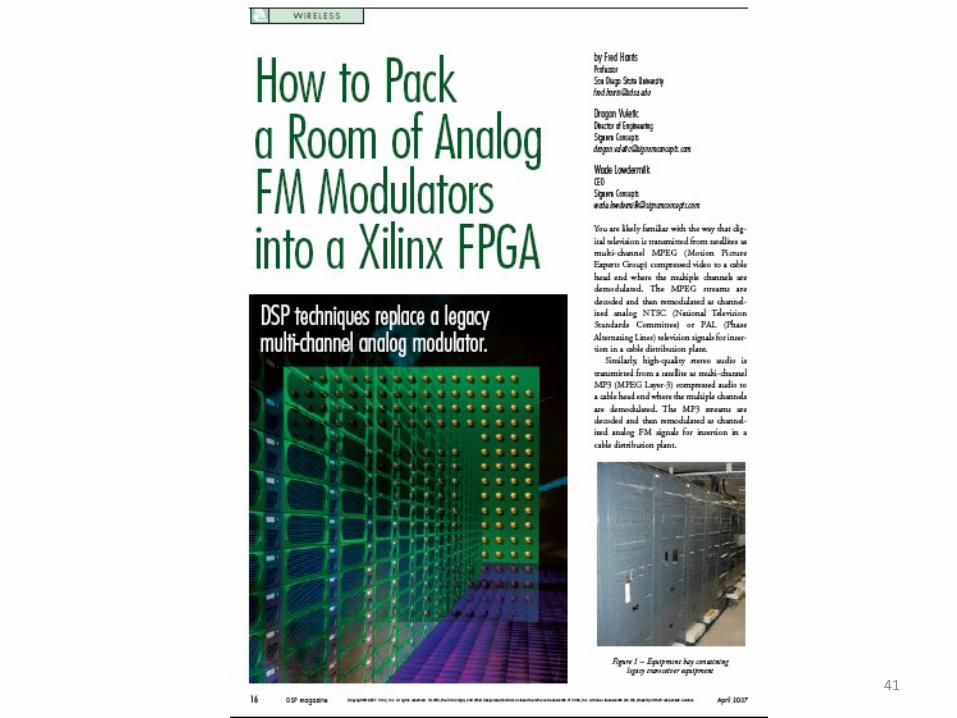
Equipment Bay: 192-Stereo FM Modulators
35

Conversation with Client!• How big a room will we need to house the DSP
version of this Transceiver?
• Answer: I think it will fit on one chip.
• Response: Don’t be Absurd, You Can’t Pack a Room into a Single Chip!
• Results: 48-Analog Devices Blackfin Processors to Demodulate 192 MP3 Stereo Channels.
• 1 Virtex V-4 for 192 Digital Stereo FM Modulators and 256 Channel Channelizer @ 293 kHz Bandwidth per channel. (60% of Chip)
36

Prototype Analog Stereo FM Modulator
dbx
Encode
dbx
Encode
50- sec
Pre-emph
75- sec
Pre-emph
50- sec
Pre-emph
LPF
14 kHz
LPF
14 kHz
LPF
7.5 kHz
BPF
15-50 kHz
BPF
60-90 kHz
VCO
32 kHz
VCO
80 kHz
100. .
0. .
3.2 MHz
3.2 MHz
Left
Right
SCA
L+ R
L - R IF
Output
37

DSP Based Stereo FM Modulator
dbx
Encoder
dbx
Encoder
LPF
14-kHz
LPF
14-kHz
LPF
14-kHz
BPF
35-kHz
BPF
30-kHz
DDS FM-MOD
&
Up-Converter
DDS FM-MOD
&
Up-Converter
50-usec
Pre-emph
50-usec
Pre-emph
75-usec
Pre-emph
48-to-293
Arb itrary
Re-Sample
48-to-293
Arb itrary
Re-Sample
48-to-293
Arb itrary
Re-Sample
Gain
Gain
Gain
Gain
IIR
IIR
KACC
KACC
IIR IIR
IIR
IIRIIR
IIRSCA
Left
Right
(L+ R)
(L-R)
32 kHz
32 kHz
CORDIC
CORDIC
Satellite Clock Domain Transceiver Clock Domain
38

256 Channel Channelizer for 50-MHz
Digital IF Sampled at 225.024 MHz
Radix-2 Butterfly of two 128-Point FFT’s
25
6 C
ha
nn
els
1:2
Up
_Sa
mp
ler
25
6 C
ha
nn
els
Ad
de
r
OddSamples
EvenSamples
12
8 P
oin
t FFT
12
8 P
oin
t FFT
12
8 P
ath
Po
lyp
ha
se F
ilte
r
1
1-T
ap
s Pe
r Pa
th1
28 P
ath
Po
lyp
ha
se F
ilte
r
1
1-T
ap
s Pe
r Pa
th
Ha
lf Ba
nd
Ph
ase
Shift
1-to-3Up-Sample
DDS
Quantize DAC
50 MHz
225.024 Mhz
225.024 Mhz
75.008 Mhz
39

40
41

42