international journal of scientific & engineering … · unified power quality conditioner ......
TRANSCRIPT
International Journal of Scientific & Engineering Research, Volume 6, Issue 7, July-2015 72 ISSN 2229-5518
IJSER © 2015 http://www.ijser.org
Power Quality Improvement using Unified Power Quality Conditioner with Distributed Generation
Anagha R. Tembhurne1 S.S.Dhamse2
1 M.E. Student, Electrical Engineering Department, Government College of Engineering, Aurangabad, India. 2 Faculty, Electrical Engineering Department, Government College of Engineering, Aurangabad, India.
Abstract— Recently power quality has become more important issue. Now a day’s power electronics based appliances are widely used in industries and in distribution system which creates more power quality problems. The power electronics based power conditioning devices can be an effective solution to improve power quality in power system. Unified Power Quality Conditioner (UPQC) is one of the custom power devices which are used to solve voltage and current related problems simultaneously. In this paper, combined operation of UPQC with Distributed Generation (DG) is discussed. This system integrated with wind energy is able to compensate voltage sag/swell, load current disturbances. Also proposed system is able to compensate voltage interruption and active power transfer to load and source in both interconnected and islanding mode and help to improve power quality. The operation of UPQC with DG has been evaluated through simulation studies using MATLAB/SIMULINK software.
Index Terms— Uninterruptible Power Supplies (UPS), Unified Power Quality Conditioner (UPQC), Distributed Generation (DG), Point of Common Coupling (PCC), Voltage Source Inverter (VSI), Distribution Static Compensator (DSTATCOM), Dynamic Voltage Restorer (DVR), Fast Fourier Transform (FFT).
1 INTRODUCTION
N electrical power system power electronics devices plays an important role. In distribution system it has three aspect first one is that introduces valuable industrial and domestic
equipments, second one is that creates problems, third one is that help to solve problems. Now a day’s modern semiconduc-tor switching devices such as controlled rectifiers, Uninter-ruptible Power Supplies (UPS), arc furnaces etc. are widely used particularly in domestic and industrial loads.
These non linear loads create power quality problems such as voltage sag, voltage swell, voltage interruption, voltage flickers, voltage spikes, harmonics etc. Such poor power quali-ty causes increase in power losses and other remarkable ab-normalities in distribution sides. Thus, it is very important to maintain a high standard of power quality. Earlier passive filters were used to solve power quality problems. However because of some limitations of passive filters, now a day’s cus-tom power devices are used to solve power quality problems in distribution side.
The compensating custom power devices are used for ac-tive filtering, load balancing, power factor improvement and voltage regulating (sag/swell).There are three types of custom power devices: Distribution Static Compensator (DSTAT-COM), Dynamic Voltage Restorer (DVR) and Unified Power Quality Conditioner (UPQC). Unified Power Quality Conditioner (UPQC) is one of the custom power devices, which can solve voltage and current related problem simultaneously. This is connected before load to make load voltage distortion free and at the same time reac-tive current drawn from source should be compensated in such a way that the currents at source side would be in phase with supply voltage. The interest in Distributed Generation (DG) has been in-creased rapidly. The world wide concern about environmental pollution and the energy shortage has led to the increasing interest in generation of renewable electrical energy. As Dis-
tribution Generation (DG) play very important role in power system and help to solve many problems that ac conventional power system has. There are several DGs such as PV system, fuel cell, wind turbine. Wind power has become fastest grow-ing energy source among various renewable energy source. In this paper deals with combined operation of UPQC with wind energy and output of DG system is connected to DC bus of UPQC. The UPQC with DG help to compensate Voltage and current power quality problems and have give additional ben-efit by providing the power to load whenever voltage inter-ruption occur with source side [1].
This paper discussed combined operation of UPQC with DG and this system is integrated with wind energy. The pro-posed system is able to compensate voltage sag/swell, load current disturbances. In addition to this it is able to compen-sate voltage interruption and active power transfer to load and source in both interconnected and islanding mode and help to improve power quality. The operation of UPQC with DG has been evaluated through simulation studies using MATLAB/SIMULINK software [2].
2 SYSTEM DESCRIPTION UPQC has two voltage-source inverters which are connected back to back by common DC bus. A series inverter is connect-ed through transformer between source and PCC and a shunt inverter is connected across load. Series inverter is responsible for mitigation of supply side disturbances such as voltage sag/swell, flickers, voltage unbalance. It inserts voltage so as to maintain the load voltage at desire level, balanced and dis-tortion free. The shunt inverter is responsible for mitigating the current related problems caused by consumers such as poor power factor, load harmonic currents, load unbalance etc. It injects current in system in such a way that source current become balanced, sinusoids and in phase with the supply
I
IJSER

International Journal of Scientific & Engineering Research, Volume 6, Issue 7, July-2015 73 ISSN 2229-5518
IJSER © 2015 http://www.ijser.org
voltage. The general block diagram of UPQC is shown in fig-ure 1.
fig1. General block diagram of UPQC
fig2. Proposed system
3 CONTROLLER DESIGN 3.1 Extraction of Unit Vector Template Input voltage source contains fundamental and other distorted component at PCC. The UPQC should separate out fundamen-tal positive sequence components from other components. The unit vector template can be obtained by multiplying input voltage with gain which is equal to 1/Vm, where Vm is nothing but the peak amplitude of fundamental input voltage. For synchronization of signals these unit vector templates are passed through a Phase Lock Loop (PLL) system and finally we get the unit vector templates for different phases [5].
In this paper, the system under consideration is as shown in figure 2. It consists of three phase four wire UPQC with wind energy source as DG and its output is connected to DC bus of UPQC. The system neutral is connected to the negative termi-nal of DC link voltage to avoid the requirement of fourth leg in Voltage Source Inverter (VSI) of shunt active filter [3],[4].This system has two modes of operation - intercon-nected mode in which DG provide power to source and load and islanding mode in which DG provide power to load within its power rating. The proposed system also consists of two DC storage device but each leg of VSI can be controlled independently. , are three phase source voltages , , are the terminal voltages and voltages injected by series active filters , , and of phase a, b and c respectively. The three phase source currents are , , , .The load currents are , and current injected by shunt active filter are , , .The feeder resistance and inductance are Rs and Ls and respec-tively. The interfacing inductance and resistance of shunt ac-tive filter are Lf and Rf respectively. The interfacing induct-ance and capacitance of series active filter Lse are Cse and re-spectively. The total DC link voltage is and In is the neutral current.
3.2 Generation of Reference Compensator Currents The terminal voltage becomes unbalanced and distorted whenever unbalanced and distorted load current flowing through the feeder impedance. The series active filters makes the voltages at PCC balanced and sinusoidal but it still con-tains switching frequency components and they contain some distortions. If this terminal voltage used for generating shunt
sav sbv scv,
)sin( 120−= tbU ω
tav tbv tcvinjav injbv
injcvsai scisbi lcilbi,lai
fai fbi fci
dcdcdcdcbus vvvv 2)21( =+
)240sin( −= tcU ω
)sin( tUa ω=
IJSER

International Journal of Scientific & Engineering Research, Volume 6, Issue 7, July-2015 74 ISSN 2229-5518
IJSER © 2015 http://www.ijser.org
filter current reference then it results in erroneous compensa-tion. Thus, fundamental positive sequence voltages v+la1(t), v+lb1 (t), and v+lc1 (t) are extracted from PCC and used to gen-erate reference current for shunt active filter. The equation for reference compensator current is given in equation (1). In this equation Plavg is average load power and is obtained using a moving average filter of one cycle window of time T in se-conds. Ploss denotes the switching losses and ohmic losses and generated using a capacitor voltage PI controller. The term is desired phase angle between the source voltage and current and for unity power factor, 𝛾 is set to zero [3], [4], [6].
(1)
Where,
This gives balanced source currents after compensation. The reference voltage for series inverter is
=desired load voltage and = reference series active fil-ter voltage. The reference and actual quantities are given to the hysteresis current controller in order to get switching command for VSI switches. Whenever error limit exceeds a specified tolerance band ±ℎ then switching command is given to VSI switches [7]. The Control block diagram of UPQC is as shown in figure 3.
(a)
(b) fig3. UPQC control part (a) series inverter control (b) shunt
inverter control
4 WIND ENERGY GENERATING SYSTEM In this system, the wind generation is based on constant speed topology with pitch control turbine and induction generator is used in this system because of its simplicity as it does not re-quire a separate field circuit and diode bridge rectifier is used to convert power generated by induction generator into dc power. The output power of the turbine is given by the follow-ing equation [8].
where,
Pm Mechanical output power of the turbine (W)
CP Performance coefficient of the turbine
ρ Air density (kg/m3)
A Turbine swept area (m2)
Vwind Wind speed (m/s)
λ Tip speed ratio of the rotor blade tip speed to wind speed
β Blade pitch angle (deg)
5 MATLAB/SIMULINK MODEL The power circuit is modeled as a three phase four wire system with a nonlinear load that is composed of a three phase diode bridge rectifier with RL load as shown in figure 4.
ϕ
)()(
1
111** losslavglclbla
lasalafa PPvvviiii +∆
−+−=−=+
+++ γ
)()(
1
111** losslavglalclb
lbsblbfb PPvvviiii +∆
−+−=−=+
+++ γ
)()(
1
111** losslavglblalc
lcsclcfc PPvvviiii +∆
−+−=−=+
+++ γ
∑=
+=∆
cbajljv
,,
2)1( 3/)tan(ϕγ =
tiliinji vvv −= **
cbai ,,=*injiv*
liv 3)(2
),( windVApCmP ρβλ=IJSER

International Journal of Scientific & Engineering Research, Volume 6, Issue 7, July-2015 75 ISSN 2229-5518
IJSER © 2015 http://www.ijser.org
fig4. MATLAB/SIMULINK model of system
6 SIMULATION RESULTS In this paper, three phase four wire 230V (line-neutral) 50Hz system is considered. There are two operation modes in the proposed system. One is called the interconnected mode, in which the DG provides power to the source and the load. The other is called the islanding mode, in which the DG provides power to the load only within its power rating. The operation of proposed system was verified through MATLAB/SIMULINK software.
Fig.5 shows the waveforms of source current, shunt invert-
er current and load current respectively. When a non-linear load injects harmonic current then it can be compensated us-ing shunt inverter current of UPQC to make source current sinusoidal.
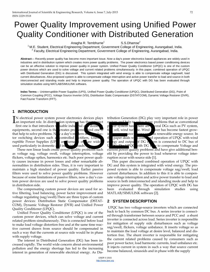
Fig.6 shows the Fast Fourier Transform (FFT) analysis of load current and source current. As shown in FFT analysis, the Total Harmonic Distortion (THD) of supply current is 0.69% and that of load current is 28%.
fig5. Current harmonic compensation (a) Source current (b) Shunt inverter current (c) Load current
(a) (b)
s c
sag2
s c
sag1
s c
sag
Discrete,Ts = 5e-005 s
powergui
measurements
i +-
in
+v e
-v e
WInd
v +-
v +-
A B C
a b c
A B C
a b c
A
B
C
a
b
c
A
B
C
a
b
c
Subsystem
Rf2Rf1Rf
Lse3
Lse2
Lse1
Lf2Lf1Lf
g CE
g CE
g CE
g CE
g CE
g CE
g CE
g CE
g CE
g CE
g CE
g CE
Inuetral
Goto2
Vdc2
Goto1
Vdc1
Goto
S2a S4a S6a
S5aS3a
S2 S4 S6
S5S3S1
S1a
Cse3Cse2
Cse1
12
3
12
2
12
1
IJSER
International Journal of Scientific & Engineering Research, Volume 6, Issue 7, July-2015 76 ISSN 2229-5518
IJSER © 2015 http://www.ijser.org
fig6. Fast Fourier Transform (FFT) analysis of (a) Load current (b) Source current
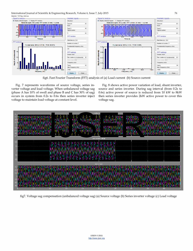
Fig. 7 represents waveforms of source voltage, series in-verter voltage and load voltage. When unbalanced voltage sag (phase A has 10% of swell and phase B and C has 30% of sag) occurs in system from 0.2s to 0.6s then series inverter inject voltage to maintain load voltage at constant level.
Fig. 8 shows active power variation of load, shunt inverter, source and series inverter. During sag interval (from 0.2s to 0.6s) active power of source is reduced from 10 kW to 8kW then series inverter provides 2kW active power to cover this voltage sag.
fig7. Voltage sag compensation (unbalanced voltage sag) (a) Source voltage (b) Series inverter voltage (c) Load voltage
IJSER

International Journal of Scientific & Engineering Research, Volume 6, Issue 7, July-2015 77 ISSN 2229-5518
IJSER © 2015 http://www.ijser.org
fig8. Active power of (a) Load (b) Shunt inverter (c) Source (d) Series inverter
Fig.9 shows waveforms of source voltage, shunt inverter
voltage and load voltage. When voltage interruption occurs from 0.2s to 0.6s then during that interval shunt inverter inject voltage to maintain load voltage constant.
Fig.10 shows the active power of load, shunt inverter, source and series inverter.
In forward flow mode, shunt inverter with DG supplies power to the load in parallel with the main source. During normal operation, source and shunt inverter provides 10kW power to load respectively. But when voltage interruption occurs (from 0.2s to 0.6s) active power of source becomes ze-ro and during this interval only shunt inverter provides 20kW active power to load.
fig9. Voltage interruption (forward flow mode) (a) Source voltage (b) shunt inverter voltage (c) load voltage
IJSER
International Journal of Scientific & Engineering Research, Volume 6, Issue 7, July-2015 78 ISSN 2229-5518
IJSER © 2015 http://www.ijser.org
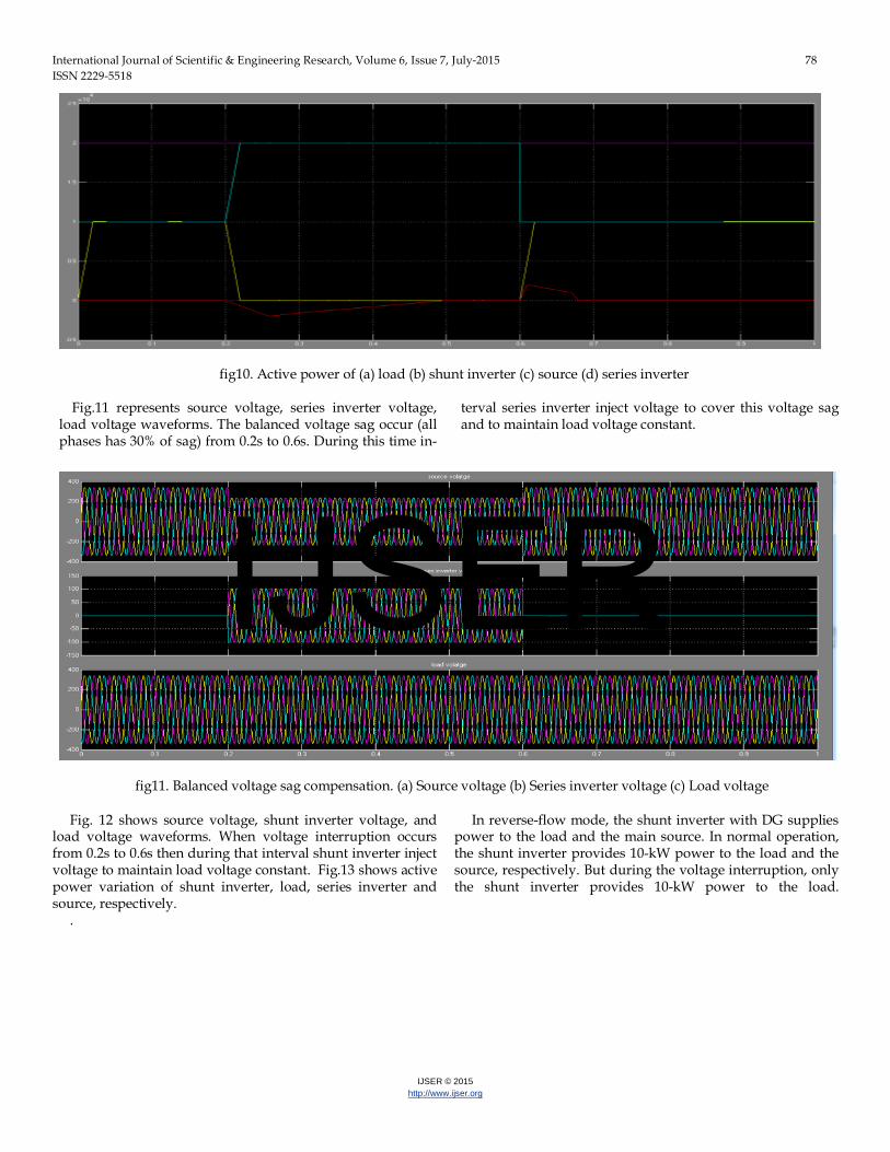
fig10. Active power of (a) load (b) shunt inverter (c) source (d) series inverter
Fig.11 represents source voltage, series inverter voltage,
load voltage waveforms. The balanced voltage sag occur (all phases has 30% of sag) from 0.2s to 0.6s. During this time in-
terval series inverter inject voltage to cover this voltage sag and to maintain load voltage constant.
fig11. Balanced voltage sag compensation. (a) Source voltage (b) Series inverter voltage (c) Load voltage
Fig. 12 shows source voltage, shunt inverter voltage, and
load voltage waveforms. When voltage interruption occurs from 0.2s to 0.6s then during that interval shunt inverter inject voltage to maintain load voltage constant. Fig.13 shows active power variation of shunt inverter, load, series inverter and source, respectively.
In reverse-flow mode, the shunt inverter with DG supplies power to the load and the main source. In normal operation, the shunt inverter provides 10-kW power to the load and the source, respectively. But during the voltage interruption, only the shunt inverter provides 10-kW power to the load.
.
IJSER

International Journal of Scientific & Engineering Research, Volume 6, Issue 7, July-2015 79 ISSN 2229-5518
IJSER © 2015 http://www.ijser.org
fig12. Voltage interruption (reverse flow mode) (a) Source voltage (b) Shunt inverter voltage (c) Load voltage
fig13. Variation of active power of (a) Shunt inverter (b) Load (c) Series inverter (d) Source
7 CONCLUSION In this paper, the combined operation of UPQC with DG is explained. The proposed system is composed of series and shunt inverter, wind energy system connected to the DC link through rectifier. The proposed system is able to compensate voltage sag, voltage swell, voltage interruption and current harmonics in interconnected and islanding mode.
Hence, the proposed system improves power quality at the point of installation on power distribution system or industrial power systems. The operation of UPQC with DG has been evaluated through simulation studies using MATLAB/SIMULINK software. REFERENCES [1] Vinod Khadkikar, Member, IEEE,” Enhancing Electric Power Quality Using UPQC:A Comprehensive Overview”, IEEE Transactions On Power Electronics, Vol. 27, No. 5, May 2012.
[2] B. Han, Senior Member, Ieee, B. Bae, H. Kim, And S. Baek,” Combined Operation Of Unified Power-Quality Conditioner With Distributed Gen-eration”, IEEE Transactions On Power Delivery, Vol. 21, No. 1, January 2006. [3] Srinivas Bhaskar Karanki, Nagesh Geddada, Student Member, IEEE, Mahesh K. Mishra, Senior Member, IEEE,B. Kalyan Kumar, Member, IEEE,’’ A Modified Three-Phase Four Wire UPQC Topology with Reduced DC-Link Voltage Rating’’ 2011 IEEE. [4] P. Divya Swathi,K. Vijay Kumar,” A New Reduced Type Three Phase Four Wire UPQC Topology for PQ features using VPI” IJIFR volume 2 issue 5 January 2015. [5] Kuldeep Kumar Singh, J. K Dwivedi,” Performance Study of Unified Power Quality Conditioner Using Matlab Simulink”, International Journal Of Scientific & Technology Research Volume 1, Issue 11, December 2012. [6] S. Srikanthan and Mahesh Kumar Mishra, Senior Member, IEEE, “DC Capacitor Voltage Equalization in Neutral Clamped Inverters for DSTAT-
IJSER

International Journal of Scientific & Engineering Research, Volume 6, Issue 7, July-2015 80 ISSN 2229-5518
IJSER © 2015 http://www.ijser.org
COM Application”, IEEE Transactions On Industrial Electronics, Vol. 57, No. 8, August 2010. [7] M.Aziz, Vinod Kumar, Aasha Chauhan, Bharti Thakur,” Power Quali-ty Improvement by Suppression of Current Harmonics Using Hysteresis Controller Technique”,International Journal of Recent Technology and Engineering volume-2,Issue-2,May 2013. [8] Sharad W. Mohod, Member, IEEE, and Mohan V. Aware,” A STAT-COM-Control Scheme for Grid Connected Wind Energy System for Power Quality Improvement”, IEEE Systems Journal, Vol. 4, No. 3, September 2010.
IJSER