international journal of heat and mass transfer · study of the critical heat flux condition with...
TRANSCRIPT

International Journal of Heat and Mass Transfer 52 (2009) 3235–3249
Contents lists available at ScienceDirect
International Journal of Heat and Mass Transfer
journal homepage: www.elsevier .com/locate/ i jhmt
Study of the critical heat flux condition with water and R-123 during flow boilingin microtubes. Part I: Experimental results and discussion of parametric effects
A.P. Roday, M.K. Jensen *
Department of Mechanical, Aerospace and Nuclear Engineering, Rensselaer Polytechnic Institute, Troy, NY 12180-3590, USA
a r t i c l e i n f o
Available online 9 March 2009
Keywords:CHFBoilingWaterR-123Flow patternQualitySubcooledSaturatedMicrotube
0017-9310/$ - see front matter � 2009 Elsevier Ltd. Adoi:10.1016/j.ijheatmasstransfer.2009.02.003
* Corresponding author.E-mail address: [email protected] (M.K. Jensen).
a b s t r a c t
Extensive experimentation was performed to obtain flow boiling critical heat flux data in single stainlesssteel microtubes with diameters from 0.286 to 0.700 mm over a wide range of mass fluxes, inlet subcoo-lings, and exit pressures for two different working fluids (water and R-123). The effect of different oper-ating parameters – mass flux, inlet subcooling, exit quality, heated length and diameter – were assessedin detail (Part I of the paper). The conventional DNB-type behavior is observed in the high subcooledregion, and the typical dryout type behavior is seen in the high-quality saturated region when the flowis completely annular. The flow in transitional flow patterns (churn–annular or slug–annular) causes apeculiar increase of CHF with exit quality. Also, the increased void fraction near the saturated regionin subcooled boiling results in increased subcooled CHF values. Part II of the paper deals with comparisonof data with existing correlations and development of a new correlation to predict the CHF condition inthe subcooled liquid region.
� 2009 Elsevier Ltd. All rights reserved.
1. Introduction
In heat transfer engineering, the thermal management of elec-tronic devices has become challenging due to the continuous andrapid development of integrated circuit technology. With the in-creased packaging density and performance of microelectronic de-vices, IC chip power has significantly risen in the last two decades.This imposes a practical limit on traditional cooling approachessuch as natural and forced convection using air. The use of two-phase cooling has many attractive features from a thermal per-spective, such as reduced volume requirements when removinglarge amounts of heat and operating with lower temperature dif-ferences. In contrast to the above heat flux controlled applications,in modern wall temperature controlled situations, with the devel-opment of nanotechnology and fuel-cell technology, more compactand enhanced heat exchangers are being designed. Ultra-compactheat exchangers typically have surface area densities as high as10,000 m2/m3 [1]. Both of the above applications are characterizedby channels having dimensions in the 100–1000 lm range. Duringflow boiling, the critical heat flux (CHF) condition sets an upperlimit on the heat transfer and this should be understood well to de-sign efficient micron-sized heat transfer devices.
There are few investigations of CHF studies in microchannelsand mini/micro circular tubes. There have been some studies intubes with smaller dimensions (up to about 0.3-mm) involving
ll rights reserved.
very high mass velocities intended for extremely high heat flux re-moval as in fusion reactors [2,3]. Celata et al. [4] have conductedsubcooled CHF studies in tube diameters as small as 0.25 mm,but these were, again, for very high heat fluxes (up to 70 MW/m2) and high mass fluxes (greater than 5000 kg/m2s) in the fusiontechnology application. Studies at lower mass fluxes, intended forapplications as mentioned above, are limited. Nariai et al. [5] re-ported CHF studies with water at ambient exit pressure in stainlesssteel tubes with inside diameter of 1-mm; tests were performedfrom the subcooled to the quality region (very close to zero qual-ity) for high mass fluxes ranging from 7000 to 11,000 kg/m2s. Theyindicated that the CHF decreased with an increase in exit quality inthe subcooled region. It has a minimum in this region very close tozero quality. As quality was further increased to a positive valuethe CHF increased sharply and, thereafter, had a decreasing trendwith increases in quality. The maximum exit quality in their datawas 0.05. A similar trend was observed by Bergles et al. [6] forCHF with deionized water in a stainless steel 2.38-mm tube withL/d = 15, mass flux of 3000 kg/m2s, and an exit pressure of 207 kPa.
Roach et al. [7] studied the CHF associated with flow boiling ofsubcooled water in circular tubes with diameters of 1.17-mm(L/d = 137) and 1.45-mm (L/d = 110), mass velocities from 250 to1000 kg/m2s, exit pressures from 344 to 1043 kPa, and inlet tem-peratures from 49 to 72 �C. They observed the CHF condition atvery high exit qualities (around 0.8) indicating dryout. They foundthat in both the tube sizes for pressure around 100 psi and massflux about 800 kg/m2s, CHF did not occur at all, and a smooth tran-sition from nucleate to film boiling took place.

Nomenclature
G mass flux, kg/m2sJ superficial velocity, m/sL length of the tube, mmNu Nusselt numberP Pressure, kPaPr Prandtl numberQ volumetric flow rate, m3/sRe Reynolds numberT temperature, �CWe Weber numberd diameter, mmh specific enthalpy, J/kgx quality
Greek lettersDT temperature difference, �CDp pressure difference, Paq density, kg/m3
r surface tension, N/md axial location, mm
SubscriptsT totalTS test sectionc criticald diameterexit at exitf liquidfg liquid–vaporg vaporh heatedi inletin inside, tubeo outletout outside, tubesat saturationsh shuntsub subcooling, inletw wall
3236 A.P. Roday, M.K. Jensen / International Journal of Heat and Mass Transfer 52 (2009) 3235–3249
CHF experiments were performed by Lazarek and Black [8] withR-113 in a stainless steel tube of inside diameter 3.15-mm(L/d = 40) in a vertical orientation. The mass velocities were inthe range of 140–740 kg/m2s. Inlet subcooling varied between 3and 73 �C. They found that the CHF occurred at very high exit qual-ities (from 0.5 to 0.8). Following the power increase, the wall tem-peratures underwent progressively large oscillations due tointermittent rewetting of the passage wall. CHF occurred at the exitof the heated test section.
Qu and Mudawar [9] measured the CHF for a water-cooled micro-channel heat sink which contained 21 parallel 215 � 821 lm chan-nels. The tests were conducted with deionized water over a massvelocity range of 86–368 kg/m2s, inlet temperatures of 30 and60 �C, and outlet pressure of 113 kPa. CHF was found to increasewith the increase in mass velocity, but virtually independent of inlettemperature.
Yu et al. [10] carried out CHF experiments with water in a stain-less steel 2.98-mm inside diameter tubing (Lh/d = 305) and a pres-sure of about 200 kPa. The outside diameter of the test section was4.76-mm. CHF was found to decrease with a decrease in mass flux(mass fluxes varied between 50 and 200 kg/m2s). CHF qualitieswere found to be relatively high, above 0.5. Lezzi et al. [11] re-ported experimental results on CHF in forced convection boilingof water in a horizontal tube of diameter 1-mm and L/d = 250,500, and 1000. The mass flux was varied between 800 and2700 kg/m2s. In all the cases the quality at the outlet was high(greater than 0.6), and the critical heat flux was reached throughdryout.
Jiang et al. [12] conducted CHF studies with water with anarray of microchannels of either 35 or 58 channels each of 40-lm hydraulic diameter and either 10 or 34 channels of 80-lmhydraulic diameter. In all the tested devices, the wall temperatureincreased almost linearly with heat flux until the onset of CHFcondition was developed. They concluded that due to the micro-scale size of the channels, a stable vapor core was establishedin the microchannel at an early stage such that the evaporationat the liquid film–vapor core interface became the dominantheat transfer mechanism. The typical bubbly flow where thebubbles form, grow, and detach from the channel wall wassuppressed.
Recently, Wojtan et al. [13] investigated saturated critical heatflux with R-134a and R-245fa in a single uniformly heated micro-channel of 0.5 and 0.8 mm internal diameter. They did not find anyinfluence of inlet subcooling on CHF, but at the same time theyfound the CHF to decrease with an increase in exit quality; how-ever, the range of inlet subcooling considered was very limitedranging from 4.5 to 12 �C.
Flow instabilities can severely affect the tests conducted todetermine the CHF condition, and instabilities need to be ad-dressed when performing the CHF experiments. With the absenceof an upstream throttle valve, as in studies by Jiang et al. [12], thecompressible volume instability could be likely responsible for areduced CHF value. Qu and Mudawar [9] took care to address thisinstability by installing a throttle valve upstream of the heat sinkand found that severe flow oscillations occurred when the valvewas open; by throttling this valve, the oscillations were virtuallyeliminated. However, Qu and Mudawar observed an unusual phe-nomenon as CHF approached; there was a vapor backflow from allthe channels towards the inlet plenum and this was responsible forthe lack of inlet subcooling effect seen in the CHF data as men-tioned previously. In case of single microchannels, this can be ta-ken care of by having a very high upstream pressure drop as isseen in the studies described in a subsequent section by Rodayet al. [14]. In the case of parallel microchannels, improved fabrica-tion techniques can be used to employ flow restrictions at the inletof each channel to accomplish the pressure drop needed [15] and,thus, avoid excursive instabilities observed by Qu and Mudawar.This technique was used by Kos�ar et al. [16], who employed inletrestrictors to study the suppression of flow boiling oscillations ina silicon microchannel device having five channels of size 200-lm wide and 264-lm deep, 1 cm long. Using the same device,Kos�ar and Peles [17] studied the CHF condition of R-123 at exitpressures ranging from 227 to 520 kPa. CHF data were obtainedover heat fluxes from 53 to 196 W/cm2 and mass fluxes from 291to 1118 kg/m2s. Flow images and high exit qualities suggested thatdryout was the leading CHF mechanism. CHF increased fairly line-arly with mass flux. Kuan and Kandlikar [18] studied the effect offlow boiling stability on CHF with R-123 in six parallel microchan-nels of hydraulic diameter 546.5-lm (cross-sectional area of eachmicrochannel is 1054-lm � 157-lm) machined on a copper block

A.P. Roday, M.K. Jensen / International Journal of Heat and Mass Transfer 52 (2009) 3235–3249 3237
of dimensions 88.9 mm � 29.6 mm by using pressure drop ele-ments (PDE) which were expected to help reduce vapor backflow;however, no visual flow patterns were reported. They developed atheoretical model to represent the CHF mechanism and correlatedit with their experimental data. Their results show a decrease inthe CHF value with the use of restrictors which is contrary to whatis expected. Since the actual design of the restrictors is not well de-scribed, the reasons for this behavior are not clear. Better design ofthe restrictors is needed to control this instability as in the study ofKos�ar et al. [16], who used microfabricated orifices which were apart of the microchannel device.
The CHF condition has received much less attention than the boil-ing heat transfer coefficient. The studies dealing with CHF in smalldiameter tubes for low mass fluxes are limited although there havebeen studies in small tube diameters down to about 0.3 mm, butsuch studies involved very high mass fluxes [3]. The data availablefor tubes are those for flow boiling of R-113 and water. There arefew data for any of the hydro chlorofluorocarbons (HCFCs). Thereare few studies for CHF at sub-atmospheric pressures or studiesclose to ambient pressure with low mass fluxes. There are not en-ough data to analyze the effect of the different variables (such asmass flux, pressure, exit quality, tube diameter) on the CHFcondition.
There are numerous discrepancies in the existing data about theCHF condition. Thus, there is no general agreement on the mini/microchannel CHF studies conducted so far. For example, in mini-channels, Roach et al. [7] found the CHF to increase with increasingchannel diameter, but Bergles et al. [6] found an inverse depen-dence of diameter on CHF. Oh and Englert [19] found a weak linearrelationship between inlet subcooling and CHF, but Bowers andMudawar [20] found that the CHF was not at all affected by the in-let subcooling during their studies in parallel microchannels. Woj-tan et al. [13] also found, in their studies with single tubes, that theCHF was not dependent on inlet subcooling. The data by Yu et al.[10] indicated that the CHF increased with an increase in exit qual-ity, but the Wojtan et al. [13] data depicts the opposite effect. TheCHF studies by Roach et al. [7] shows that the CHF increases withincreasing pressure, but the data in some studies [13] do not showa strong dependence of pressure on CHF. Many researchers haveattempted to predict their data with existing correlations, but withmixed results. Many different correlations have been developed,but they are mostly applicable to the limited data range over whichthe experiments were conducted. Conjugate heat transfer effectshave been neglected, and the effect of flow instabilities have notbeen investigated properly during some of the experiments. The ef-fects of axial conduction through the tube walls or through theblocks on which the channels are machined can significantly alterthe CHF condition. Most of the experiments have ignored this as-pect. Likewise, flow oscillations can have a significant negative ef-fect on the CHF condition. Generally, flow distribution in parallelchannels tends to be non-uniform. Since the CHF condition isdependent on flow rate, most of the data from the experimentsusing parallel channels are not reliable as the flow rate throughthe individual channels is not exactly known. The current literatureon CHF in microchannels is not sufficient to predict the boiling cri-sis over the range of parameters typically encountered in applica-tions where such small-size channels find potential use. Likewise,there is a clear lack of accurate and validated models to predicttwo-phase heat transfer characteristics. Thus, the objectives ofthe present study are:
� To gain a better understanding of the CHF condition in micro-channels, so that the CHF condition can be predicted with confi-dence over a wide range of operating parameters such aschannel material, type of fluid, geometrical sizes, mass fluxes,operating pressures and inlet subcoolings.
� To understand the impact of flow oscillations on the critical heatflux condition.
� To determine the flow patterns from the experimental CHF datausing existing flow pattern maps/models.
� To assess the capability of using existing correlations for con-ventionally sized channels and available correlations for micro-channels to predict the onset of the critical condition inmicrochannels and develop new correlations if needed (Part IIof the paper).
2. Experimental apparatus and procedures
For the CHF experiments, a flow loop was designed and con-structed to obtain experimental data on the CHF condition over awide range of operating conditions [refer Table 1(a) and (b)]. Theflow loops used for testing water and R-123 were identical, exceptthat the equipment used on the refrigerant set-up was selected tobe compatible with R-123. A schematic of the flow loop used fortesting is shown in Fig. 1.
The major components of the loop are a storage tank, flowme-ters, and the test section assembly. The tank was equipped so thatthe pressure could be varied from a vacuum to a pressure of 5 bars;likewise, it was used to degas the fluids. As a safety measure, apressure relief valve was also provided on the tank.
Fluid was circulated in the loop by imposing a pressure dif-ference between the two tanks. The fluid was heated to the de-sired temperature by passing it through a 200-mm longpreheater section. The preheated fluid was throttled before it en-tered the test section. The throttling valve controlled the inletcondition of the fluid to the test section and reduced flow insta-bilities during boiling. The preheated fluid then flowed throughthe test section. (A detailed discussion of the test section andits mounting is provided below.) A differential pressure trans-ducer measured the pressure drop across the test section length.A Bourdon-type pressure gauge recorded the pressure at the exitof the test section. Following the test section, the fluid enteredTank B from where it was later pumped back to the main stor-age Tank A.
The test sections used for obtaining boiling heat transfer andCHF data were made from individual hypodermic tubing havinga circular geometry. The diameter of each test section used inthe experiment was carefully measured using an optical micro-scope having a measuring probe attachment. The test sectionwas heated by passing DC power through it. The test sectionwas enclosed by a guard heater to minimize heat losses duringdiabatic experiments as shown in Fig. 2. A 2.0-cm thick layer ofinsulation was wrapped around the test section. A 5-cm diametercopper tube, with resistance wire and a thermocouple bonded toit, was secured over this insulation. Then another 3-cm layer ofinsulation was wrapped around the copper tube. The guard heatercovered the area from compression fitting to compression fitting.The power to this guard heater was controlled through a variabletransformer.
An automatic test section power shut-off circuit was used toprevent test section damage at CHF. The switching time of the relayis about 7 ms. Once the test section assembly was completed, T-type thermocouples (copper–constantan) were bonded to the testsection at different axial locations using a high-temperature epoxy.Thermocouples nearer to the exit of the heated section werespaced close to each other (about 2.0 mm apart) to better trackthe CHF condition. Also, one thermocouple was mounted on thetest section ahead of the heated length to check for any backflowof vapor and axial conduction away from the heated section. Pres-sure taps were provided at the two ends of the test section (about

Table 1Experimental conditions for water and R-123 CHF experiments.
Parameter Test section – A Test section – B Test section – C
(a) CHF data – waterdin (mm) 0.286 0.427 0.700dout (mm) 0.450 0.550 1.060Lh (mm) 21.66, 39.82, 57.62 59.00 70.70, 96.0LT (mm) 138.65 121.96 138.07G (kg/m2s) 320, 1570 315, 560, 870, 1570 315, 560Pexit (kPa) 26, 102 25.3, 102, 179 102DTsub (�C) 5–80a 2–50 2–80
Test section – D Test section – E Test section – F
(b) CHF data – R-123din (mm) 0.286 0.430 0.700dout (mm) 0.450 0.550 1.060Lh (mm) 17.26, 37.13, 58.91 25.37, 55.47 39.72, 90.84LT (mm) 136.20 141.70 138.07G (kg/m2s) 375, 530, 825 375, 530, 825 375, 530, 825Pexit (kPa) 165, 225b 168 168DTsub (�C) 2–25a 2–17 2–15
a The range depends on exit pressure.b For the pressure of 225 kPa the heated lengths were 17.26 and 58.91 mm.
Fig. 1. Schematic of the flow loop.
Fig. 2. Test section assembly.
3238 A.P. Roday, M.K. Jensen / International Journal of Heat and Mass Transfer 52 (2009) 3235–3249
35 mm away from the heated section). Temperature probes mea-sured the temperature of the working fluid at the inlet and exitof the test sections at the same locations as the pressure taps.The inlet and exit portions of the test section were heavily insu-lated to avoid heat loss.
Calibration of the flowmeters was done using the weigh tanktechnique of measuring the volume of fluid collected in a givenamount of time. Calibration of the Bourdon-type pressure gaugeswas done using a deadweight tester. The differential pressuretransducers were calibrated for each diaphragm using a water col-umn over the full pressure range of the transducers for the lowerdifferential pressure ranges and with deadweight tester for thehigher differential pressure range.
The fluid was degassed before circulating in the loop. This wasdone by passing high pressure argon through the water stored inthe Tank A. This gas stripped the dissolved oxygen from the fluid.The process was carried out in vacuum (about 50 kPa) so that dis-solved gases along with the argon were removed from the tank,thus leaving the tank with degassed water.
For an experimental run, the flow was set to the desired valueby adjusting the in-line valves. The exit pressure was set by con-trolling the pressure in Tank B. The preheater and guard heaterwere turned on and set to the desired values. A criterion of a max-imum ±0.5 �C variation in wall temperatures in about 15 min wasset to detect the quasi-steady state as the wall temperatures re-mained fairly constant after about 15 min indicating that a steady

A.P. Roday, M.K. Jensen / International Journal of Heat and Mass Transfer 52 (2009) 3235–3249 3239
state was attained. It took up to about 2 h to reach the initial quasi-steady state depending on the operating conditions, and about30 min for each new setting of the flow rate. For every new settingof the inlet temperature, it took another 1 h for the flow to reachsteady state. Once steady state was reached, data were recordedof those operating conditions.
A single-phase experiment was first performed, and the heatloss was estimated by comparing the sensible heat gained by thewater (inlet and outlet water temperatures were measured duringthe experiment) with the power input to the test section. Thisexperiment was done by setting the power to the test section ata particular value, and adjusting the guard heater power so thatthe guard heater temperature was only slightly above the walltemperature on the test section. This ensured minimum heat lossfrom the test section wall. The measurements of flow, temperature,and voltages were then recorded.
Next, the guard heater temperature was set close to the satura-tion temperature (corresponding to the outlet pressure). The inletfluid temperature was again set to the desired value, steady statewas reached, and then the power to the test section was increasedin progressively smaller increments until the CHF condition wasreached. This condition was marked by a nearly instantaneous risein the wall temperature of about 80–100 �C over the saturationtemperature.
3. Data reduction
The measured quantities were the total pressure drop (DpT-expt)from the differential pressure transducer, the volumetric flow rate(Q) from the flowmeter, the test section inside diameter (din), thetest section length (L), the voltage across the shunt (Vsh), voltageacross the test section (VTS), heated length of the test section (Lh),fluid inlet temperature (Tf,i), fluid exit temperature (Tf,o), the walltemperatures (Tw,o,d), and the exit pressure (Pexit). The derivedquantities included mass flow rate, mass flux, Reynolds number,heat flux, Nusselt number, and quality. An energy balance was usedto calculate local fluid conditions in the test section; CHF condi-tions were identified at the last thermocouple location. Heat lossfrom the test section was estimated by calibration of the system;the guard heater ensured a heat loss of less than ±5% of test sectionpower. Total pressure drop was calculated including entrance andexit losses and frictional losses (developing region and fully devel-oped region). The thermophysical and the thermodynamic proper-ties of water and R-123 were obtained using Engineering EquationSolver (EES). An uncertainty analysis was performed using themethod suggested by Kline and McClintock [21] for the propaga-tion of error, and uncertainties (depending on test section diame-ter) were estimated to be: mass flux, ±2.1–2.7%; Reynoldsnumber, ±2.1–2.8%; heat flux, ±5%; Nusselt number, ±5.3–5.5%;quality, ±5.8%. The details of the data reduction and uncertaintyanalysis are described in Roday [22].
4. Experimental results
Following the procedures outlined, the CHF condition wasexperimentally investigated in stainless steel microtubes of
Table 2Property comparison for R-123 and water.
Property R-123 Water
qf/qg 101–138 930–6022r (N/m) 0.012–0.013 0.056–0.065hgf (kJ/kg) 160–165 2211–2343Wed 2–25 0.5–20Pc (kPa) 3668 22064Pexit/Pc 0.045–0.061 0.001–0.008
various diameters (din) for water and R-123 over a range of massfluxes, inlet subcoolings and exit pressures (see Table 1). A totalof about 225 CHF data points were obtained during this study.
A comparison between the properties of R-123 and water basedon their respective experimental conditions (from Table 1) is pro-vided in Table 2.
4.1. Single-phase pressure drop and heat transfer – water and R-123
Single-phase studies were conducted in the test sections beforerunning CHF experiments. The experimental pressure drops wereclose (within ±10%) to that calculated from correlations for mostof the data over Re up to 1100 for all the test sections. Fig. 3 showsthis agreement for din = 0.286, 0.427, and 0.700 mm for studiesconducted with water.
During the single-phase heat transfer experiments, the flow washydrodynamically fully developed but was thermally developingfor parts or all of the test section heated length. The heat transferresults were compared with the modified Hausen correlation (forconstant heat flux) given below.
Nu ¼ 4:36þ 0:19ðRePrdin=LÞ0:8
1þ 0:117ðRePrdin=LÞ0:467 ð1Þ
This correlation overpredicted the data at lower Reynoldsnumber and underpredicted them at higher Re for all the threediameters. As seen in Fig. 4, the deviation for din = 0.427 mm[Test section B, Table 1(a)] is about �75% at lower Reynoldsnumber (Re � 50) and 25% at Re � 900. The data for the othertwo diameters were qualitatively similar. These laminar single-phase heat transfer results are consistent with other results fromthe literature [23,24].
Most of the studies on single-phase flow in microchannelswere able to measure pressure drop characteristics which wereconsistent with conventional sized channels but showed markeddeviations in heat transfer characteristics [25], similar to whatwe have observed. A definite reason for this disagreement inmicrochannels is not yet known. Single-phase pressure dropand heat transfer experiments were performed before the CHFexperiments were carried out for R-123 as well. Results showfairly good agreement of pressure drop predictions, but the Nus-selt Number was underpredicted at low Re and overpredicted athigh Re similar to that observed in experiments conducted withwater.
Fig. 3. DpT-expt/DpT-calc versus Re for din = 0.286, 0.427, and 0.700 mm.

Fig. 4. Comparison of experimental Nusselt number with modified Hausencorrelation, din = 0.427 mm.
0
5
10
15
20
25
30
0 20 40 60 80
Time [sec]
ΔP[k
Pa]
q"=247 kW/m²
q"=455 kW/m²
q"=810 kW/m²
d=0.286 mm, G=320 kg/m²s, ΔTsub=64°C
Fig. 6. Pressure drop versus time for water; G = 320 kg/m2s, DTsub = 64 �C,din = 0.286 mm.
3240 A.P. Roday, M.K. Jensen / International Journal of Heat and Mass Transfer 52 (2009) 3235–3249
4.2. Critical heat flux (CHF) studies
In the two-phase study, there were about 140 CHF data pointswith water and 85 for R-123. There are some additional data pointswhere the characteristic sharp rise in wall temperature associatedwith the CHF condition was not observed. All the data are tabu-lated in Roday [22]. Before discussing the results for each of thethree diameter tubes, the flow conditions during these experi-ments are described and plots of typical wall temperature varia-tions with heat flux are depicted in the next sub-section.
Flow was stabilized during the CHF experiments by maintaininga very high pressure drop (130–200 kPa) upstream of the test sec-tion through use of an inlet throttle valve; the rotameter float po-sition was constant. A thermocouple mounted on the test sectionwall just before the heated section did not show any appreciablevariations in temperature (the temperature was very close to theinlet water temperature), which indicated that there was no back-flow of vapor or axial conduction outwards from the heated sec-tion. The pressure drop showed only small fluctuations with time(single-phase and two-phase flow regimes) except for very close
0
5
10
15
20
0 20 40 60 80 100 120 140
Time [sec]
ΔP[k
Pa]
q"=10.6 kW/m²
q"=100 kW/m²
q"=149 kW/m²(CHF)
Fig. 5. Pressure drop versus time for water; G = 560 kg/m2s, DTsub = 38 �C,Pexit = 25 kPa, din = 0.427 mm.
to the CHF condition. One such plot of pressure drop versus timefor din = 0.427 mm, at sub-atmospheric pressure and a mass flowrate of 560 kg/m2s for water, is shown in Fig. 5. Pressure drop fluc-tuations for din = 0.286 mm are depicted in Fig. 6. The magnitudesof the fluctuations in Figs. 5 and 6 were typical of all tests.
For the flow boiling tests (water and R-123), there was a char-acteristic sharp rise in wall temperature at the point of CHF, ascan be seen in the plot of wall superheat versus heat flux depictedin Fig. 7 for water CHF data and Fig. 8 for R-123. Note, also, thatprior to the initiation of the CHF condition, often the wall temper-ature initially jumped up by about 35 �C, then dropped back; withfurther increases in heat flux, the CHF condition was reached (walltemperature was approximately 165 �C). At this point, test sectionpower was automatically shut-off to prevent test section damage.A similar observation was made in other tests with lower massfluxes where the steady increase in heat flux caused the wall tem-peratures to increase by about 40–50 �C and then fall back beforefinally attaining the CHF condition. The jumps in the wall temper-ature just prior to CHF could be due to the occurrence of drypatches on the tube wall and when the liquid occasionally rewett-ed the wall, the temperatures would fall back. CHF would occur
-40
-20
0
20
40
60
80
100
120
0 20 40 60 80 100 120 140 160
Heat Flux [kW/m²]
ΔTsa
t [°C
]
Fig. 7. Wall superheat versus heat flux for water (Pexit = 25 kPa; G = 315 kg/m2s;DTsub = 15 �C, din = 0.427 mm).

Fig. 8. Wall superheat versus heat flux for R-123 (din = 0.430 mm, DTsub = 11.3 �C,G = 375 kg/m2s, Lh = 25.37 mm).
0
100
200
300
400
500
0 500 1000 1500 200 0
Mass Flux [kg/m2s]
CH
F [k
W/m
2 ]
P=179 kPaP=102 kPaP=25.3 kPa
Fig. 10. Effect of mass flux on CHF for din = 0.427 mm with water.
Fig. 11. Effect of mass flux on CHF for R-123, din = 0.430 and 0.700 mm.
A.P. Roday, M.K. Jensen / International Journal of Heat and Mass Transfer 52 (2009) 3235–3249 3241
near the exit when the tube wall became completely dry. Lazarekand Black [8] observed a similar wall temperature response duringCHF tests in a 3.1 mm diameter tube at mass flux of about270 kg/m2s.
The characteristic CHF did not occur for some of the waterCHF experiments up to high heat fluxes, at which point powerwas shut down so that the test sections were not destroyed. Thishappened for some of the tests carried out at low values of inletsubcooling (DTsub = 2–7 �C). The wall temperature kept linearlyincreasing as the heat flux was increased. When the wall super-heats reached a relatively high value (40–60 �C), the experimentwas stopped before the CHF was observed to save the test sec-tion. For this reason, very few saturated CHF data points couldbe obtained.
4.3. Parametric effects on CHF
4.3.1. Effect of mass flux on CHFFig. 9 depicts the dependence of CHF on mass flux for the tube
diameter of 0.286 mm. The subcooled CHF data were compared at
Fig. 9. Effect of mass flux on CHF for din = 0.286 mm with water.
about a fixed value of inlet subcooling. It is seen that for the twoexit pressures (Pexit = 102 and 66 kPa), the CHF increased with massflux for all the three heated lengths. A similar mass flux effect isobserved in tests conducted with din = 0.700 and 0.427 mm. Theresults for the CHF dependence on mass flux for four different massflux values in 0.427 mm diameter tube are depicted in Fig. 10.
For R-123, the CHF increases with an increase in mass fluxat a given value of inlet subcooling. Fig. 11 shows that CHF in-creases with mass flux for both the tube diameters din = 0.430mm and 0.700 mm. A similar mass flux effect is observed fordin = 0.286 mm.
A similar mass flux dependence of CHF has been observed byother researchers such as for water at reduced pressures throughparallel microchannels of 0.227 mm hydraulic diameter [26], andfor flow of R-134a through single stainless steel tubes of 0.5 and0.8 mm inside diameter [13]. Thus, an increasing CHF with massflux is seen in studies with different fluids. However, the waterdata of Kosar et al. and the data shown here have a major differ-ence. The Kosar et al. data have significantly higher CHFs – perhapsdue to a smaller hydraulic diameter or conjugate heat transfer ef-fects since their experiments were multiple parallel channels in ahigh conductivity block (Si).

Fig. 12. Effect of inlet subcooling on CHF for din = 0.427 mm and Pexit = 25.3 kPa.
3242 A.P. Roday, M.K. Jensen / International Journal of Heat and Mass Transfer 52 (2009) 3235–3249
4.3.2. Effect of inlet subcooling and exit qualityThe effect of inlet subcooling on CHF for din = 0.427 mm is
shown in Fig. 12 at different mass fluxes. It seems, from the lim-ited data that could be obtained at higher subcoolings, that theCHF slightly decreased with a decrease in inlet subcooling forcritical qualities further away from the saturated liquid point,which is similar to conventional tubes but the number of datapoints are not enough to prove it conclusively. From Fig. 12,the slight decrease at higher subcoolings is more evident forG = 315 and 870 kg/m2s where the critical qualities are about�0.40 when compared to the other data (G = 560 and 1570kg/m2s) where this trend seems to be missing as the criticalqualities were only about �0.25. At lower subcoolings (water in-let temperature close to the saturation temperature), the CHF in-creased with a decrease in subcooling. This trend was observedat all exit pressures. For the cases where the CHF dramaticallyincreased with reduction in inlet subcooling, the exit quality atCHF was close to zero. With further decrease in inlet subcooling(DTsub � 2–4 �C), the wall temperature kept linearly increasingwith heat flux and, as previously mentioned, the experimenthad to be stopped before the CHF condition was observed.
Fig. 13. Effect of exit quality on CHF for din = 0.427 mm and Pexit = 102 kPa.
Detailed results for the effect of exit quality on CHF fordin = 0.427 mm are presented in Fig. 13. Note that in Fig. 13, theCHF first decreases with an increase in quality in the subcooled re-gion, but with a further increase in quality (near zero quality andabove), the CHF is found to have an increasing trend with quality.Much higher values of CHF are found in the region close to satura-tion when compared to the high subcooled region. With still fur-ther increases in heat flux/exit quality, the CHF condition did notoccur even when the wall superheat (DTsat = Tw � Tsat) reachedabout 40–60 �C; the wall temperature increased essentially line-arly with increases in heat flux. At this point, the experimentwas terminated to save the test section. Therefore, very few datacould be obtained in the saturation region. The results for the exitquality are consistent with the trends observed for the variation ofCHF with inlet subcooling.
In the case of test section having inside diameter of 0.700 mm, asimilar trend for inlet subcooling and exit quality was observed forexperiments conducted with both heated lengths (Lh = 70.7 and96.0 mm).
With tube diameter of 0.286 mm data trends for inlet subcool-ing and exit quality were very similar to that observed fordin = 0.427 and 0.700 mm at higher mass fluxes. However, forG = 320 kg/m2s, much higher critical qualities were found (as highas 0.9) in the saturated region for Pexit = 102 kPa (Fig. 15) and max-imum critical quality of about 0.6–0.7 was attained at the lowerexit pressure of 26 kPa. There are two interesting cases observedin the data:
1. Case I (Fig. 14) – CHF seems to initially decrease with a reduc-tion in inlet subcooling in the higher absolute value of the neg-ative critical quality region. However, the decrease is not tooevident in some of the data because the negative critical qualityband is narrow. More data at still higher inlet subcoolings overa wider range would be able to provide more insight into thisspeculation. With further decrease in inlet subcooling, CHFincreased (similar to observations for din = 0.427 and0.700 mm), and finally (when very low inlet subcoolingsapproached), CHF had a decreasing trend with quality (similarto that in conventional tubes) where the flow seems to be annu-lar as discussed in a later section on flow maps.
2. Case II – CHF seems to initially decrease with a reduction ininlet subcooling at higher negative critical quality. With furtherdecrease in inlet subcooling, CHF increased (up to low inlet
Fig. 14. Effect of inlet subcooling on CHF (din = 0.286 mm, Lh = 39.82 mm, andPexit = 102 kPa).

Fig. 15. Effect of exit quality on CHF (din = 0.286 mm, Lh = 39.82 mm, andPexit = 102 kPa).
Fig. 16. Water data flow patterns using flow-pattern map of Hassan et al. [28].
A.P. Roday, M.K. Jensen / International Journal of Heat and Mass Transfer 52 (2009) 3235–3249 3243
subcoolings). The decreasing trend of CHF with further decreasein inlet subcooling at very low subcoolings is not obvious orpresent (similar to Fig. 12) as the data fall in the transitionregime between churn and annular flow.
These data are not in apparent agreement with some other datathat exist for CHF in microchannels. For example, the data by Woj-tan et al. [13] show the CHF to be affected by exit quality, but onlya small influence of inlet subcooling is observed. However, theystate that measurements with larger inlet subcoolings were notpossible, and so the data are for subcooling ranging only from 4.5to 12 �C. They claim the observation to be in good agreement withthe results of Qu and Mudawar [9] for parallel microchannels.However, Qu and Mudawar observed parallel channel instability(vapor back flow) as the CHF was approached, resulting in a dimin-ished influence of inlet subcooling as vapor mixed with the sub-cooled inlet fluid in the plenum. Their data showed hardly anyinfluence of inlet subcooling.
The increase in CHF from subcooled to the saturated region (asobserved in the data) was also seen by Nariai et al. [5] in their stud-ies on CHF in minitubes (1–3 mm inside diameter) but with muchhigher mass fluxes (7000–11,000 kg/m2s). The maximum exitquality in their data was 0.05. Bergles et al. [27] reported similarfindings for flow of water through a 2.38 mm tube with a mass fluxof 1350 kg/m2s. They found the CHF to increase from subcooled tothe saturated region, but at qualities above 0.4, the CHF had a con-ventional decreasing trend (dryout type behavior). Similarly, thedata from Wojtan et al. [13] showed a decreasing trend of CHF withquality (x > 0.4), but no data were available at lower qualities, andthus, no comments can be made about the discontinuity from sub-cooled to saturated region.
During the present experiments it was not possible to visualizethe flow to determine the flow patterns. The data were mappedusing the flow pattern maps available for microchannels to assessthe flow condition at the instance of the CHF condition. First thewater CHF data are mapped using the flow pattern map of Hassanet al. [28]. This is a universal flow map developed for horizontalmicrochannels of diameter less than 1.0 mm. The effects of surfacetension are more significant in microchannels and this flow mapcharacterizes the flow regimes in two major categories: the surfacetension (bubbly, plug, and slug flow) and inertia dominated flowregimes (churn and annular). The redefined transition boundaries
gave a good approximation of flow regime transitions when Has-san et al. compared the flow map with the previous studies thatwere conducted in microchannels. The water CHF data of the pres-ent study mapped using the Hassan et al. flow map are shown inFig. 16 and indicate the flow-type at the instance of the CHFcondition.
The superficial liquid (Jf) and superficial gas velocities (Jg) werecalculated as
Jf ¼Gð1� xcÞ
qfð2Þ
Jg ¼Gxc
qgð3Þ
The following observations are made from this flow regimemap:
(a) Most of the data fall in the churn flow, churn–annular tran-sition or annular flow very close to the transition zone.
(b) Almost all of the data where the experiment had to bestopped to prevent destruction of the test section fell inthe churn flow regime.
(c) Most of the data from the tube diameters of 0.427 and0.700 mm were either in the churn or the churn–annulartransition zone. The churn flow is characterized by a highlyirregular interface with oscillatory flow of the liquid. Withincrease in quality in the saturated region, more vapor isgenerated, and it is possible that the waves are stabilizeddue to the high vapor. This might be a possible reason forincrease in CHF with quality during the transition asobserved in all the saturated CHF data for the tube diametersof 0.427 and 0.700 mm.
(d) Some of the data for tube diameter of 0.286 mm were inannular flow, with the remaining in churn or churn–annularregime. It is interesting to see that the data for this tubediameter far away from the churn–annular transition linecorrespond to those at very high qualities where the CHFhas a decreasing trend with inlet subcooling and CHF isalmost constant or decreases slightly with exit quality. Theflow then could be an annular flow exhibiting dryout typebehavior. For all other data points (in churn flow as well aschurn–annular transition) and even those in annular flowcloser to transition, the flow might still be churn/intermit-tent and a similar behavior as observed in other tube diam-eters is expected where the CHF increases with quality. For
3244 A.P. Roday, M.K. Jensen / International Journal of Heat and Mass Transfer 52 (2009) 3235–3249
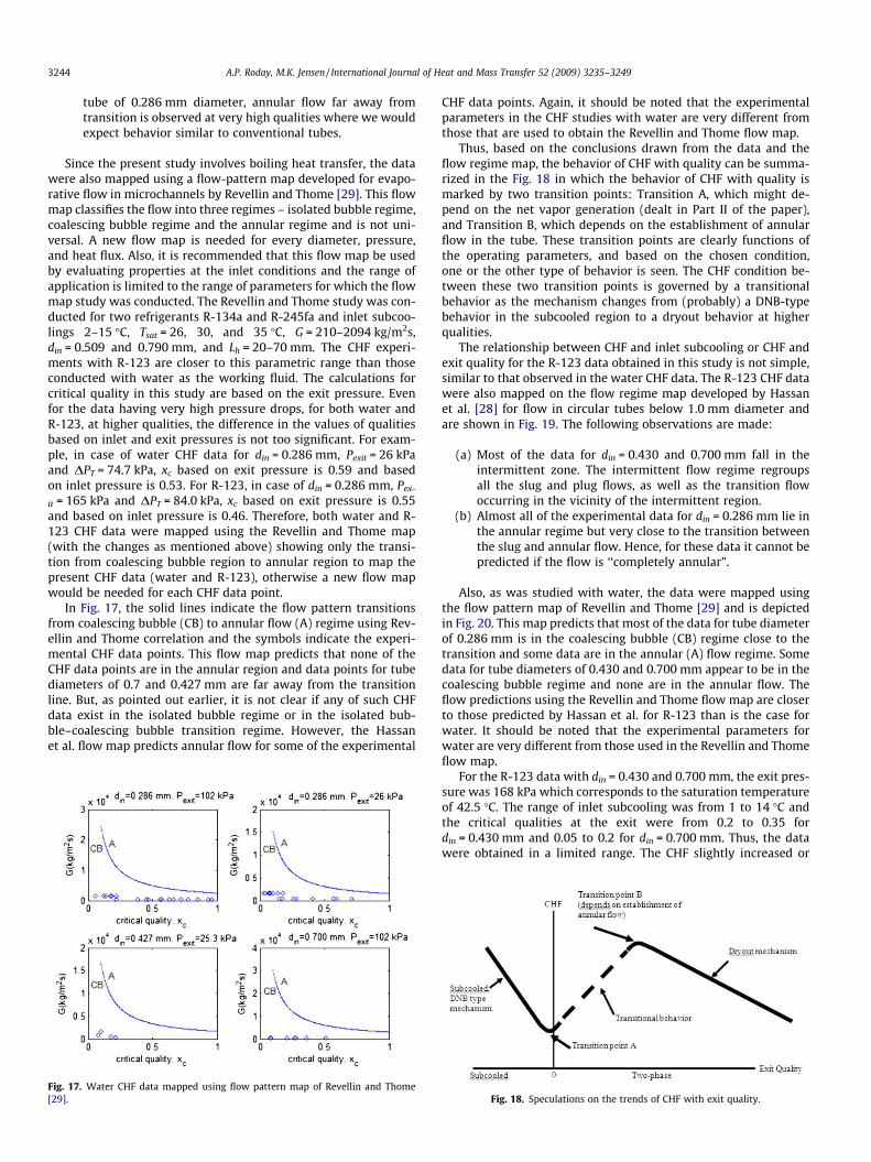
tube of 0.286 mm diameter, annular flow far away fromtransition is observed at very high qualities where we wouldexpect behavior similar to conventional tubes.
Since the present study involves boiling heat transfer, the datawere also mapped using a flow-pattern map developed for evapo-rative flow in microchannels by Revellin and Thome [29]. This flowmap classifies the flow into three regimes – isolated bubble regime,coalescing bubble regime and the annular regime and is not uni-versal. A new flow map is needed for every diameter, pressure,and heat flux. Also, it is recommended that this flow map be usedby evaluating properties at the inlet conditions and the range ofapplication is limited to the range of parameters for which the flowmap study was conducted. The Revellin and Thome study was con-ducted for two refrigerants R-134a and R-245fa and inlet subcoo-lings 2–15 �C, Tsat = 26, 30, and 35 �C, G = 210–2094 kg/m2s,din = 0.509 and 0.790 mm, and Lh = 20–70 mm. The CHF experi-ments with R-123 are closer to this parametric range than thoseconducted with water as the working fluid. The calculations forcritical quality in this study are based on the exit pressure. Evenfor the data having very high pressure drops, for both water andR-123, at higher qualities, the difference in the values of qualitiesbased on inlet and exit pressures is not too significant. For exam-ple, in case of water CHF data for din = 0.286 mm, Pexit = 26 kPaand DPT = 74.7 kPa, xc based on exit pressure is 0.59 and basedon inlet pressure is 0.53. For R-123, in case of din = 0.286 mm, Pex-
it = 165 kPa and DPT = 84.0 kPa, xc based on exit pressure is 0.55and based on inlet pressure is 0.46. Therefore, both water and R-123 CHF data were mapped using the Revellin and Thome map(with the changes as mentioned above) showing only the transi-tion from coalescing bubble region to annular region to map thepresent CHF data (water and R-123), otherwise a new flow mapwould be needed for each CHF data point.
In Fig. 17, the solid lines indicate the flow pattern transitionsfrom coalescing bubble (CB) to annular flow (A) regime using Rev-ellin and Thome correlation and the symbols indicate the experi-mental CHF data points. This flow map predicts that none of theCHF data points are in the annular region and data points for tubediameters of 0.7 and 0.427 mm are far away from the transitionline. But, as pointed out earlier, it is not clear if any of such CHFdata exist in the isolated bubble regime or in the isolated bub-ble–coalescing bubble transition regime. However, the Hassanet al. flow map predicts annular flow for some of the experimental
Fig. 17. Water CHF data mapped using flow pattern map of Revellin and Thome[29].
CHF data points. Again, it should be noted that the experimentalparameters in the CHF studies with water are very different fromthose that are used to obtain the Revellin and Thome flow map.
Thus, based on the conclusions drawn from the data and theflow regime map, the behavior of CHF with quality can be summa-rized in the Fig. 18 in which the behavior of CHF with quality ismarked by two transition points: Transition A, which might de-pend on the net vapor generation (dealt in Part II of the paper),and Transition B, which depends on the establishment of annularflow in the tube. These transition points are clearly functions ofthe operating parameters, and based on the chosen condition,one or the other type of behavior is seen. The CHF condition be-tween these two transition points is governed by a transitionalbehavior as the mechanism changes from (probably) a DNB-typebehavior in the subcooled region to a dryout behavior at higherqualities.
The relationship between CHF and inlet subcooling or CHF andexit quality for the R-123 data obtained in this study is not simple,similar to that observed in the water CHF data. The R-123 CHF datawere also mapped on the flow regime map developed by Hassanet al. [28] for flow in circular tubes below 1.0 mm diameter andare shown in Fig. 19. The following observations are made:
(a) Most of the data for din = 0.430 and 0.700 mm fall in theintermittent zone. The intermittent flow regime regroupsall the slug and plug flows, as well as the transition flowoccurring in the vicinity of the intermittent region.
(b) Almost all of the experimental data for din = 0.286 mm lie inthe annular regime but very close to the transition betweenthe slug and annular flow. Hence, for these data it cannot bepredicted if the flow is ‘‘completely annular”.
Also, as was studied with water, the data were mapped usingthe flow pattern map of Revellin and Thome [29] and is depictedin Fig. 20. This map predicts that most of the data for tube diameterof 0.286 mm is in the coalescing bubble (CB) regime close to thetransition and some data are in the annular (A) flow regime. Somedata for tube diameters of 0.430 and 0.700 mm appear to be in thecoalescing bubble regime and none are in the annular flow. Theflow predictions using the Revellin and Thome flow map are closerto those predicted by Hassan et al. for R-123 than is the case forwater. It should be noted that the experimental parameters forwater are very different from those used in the Revellin and Thomeflow map.
For the R-123 data with din = 0.430 and 0.700 mm, the exit pres-sure was 168 kPa which corresponds to the saturation temperatureof 42.5 �C. The range of inlet subcooling was from 1 to 14 �C andthe critical qualities at the exit were from 0.2 to 0.35 fordin = 0.430 mm and 0.05 to 0.2 for din = 0.700 mm. Thus, the datawere obtained in a limited range. The CHF slightly increased or
Fig. 18. Speculations on the trends of CHF with exit quality.

Fig. 19. Flow patterns for R-123 using Hassan et al. [28] flow map.
Fig. 20. Flow patterns for R-123 using Revellin and Thome [29] flow map.
Fig. 21. Effect of inlet subcooling on CHF for R-123 with din = 0.700 mm.
A.P. Roday, M.K. Jensen / International Journal of Heat and Mass Transfer 52 (2009) 3235–3249 3245
was fairly constant with a reduction in inlet subcooling for boththe tube diameters, which is contrary to that observed in conven-tional sized channels and is shown for 0.700 mm diameter inFig. 21.
Experiments conducted with test section of inside diameter0.286 mm show that the CHF first increases with reduction in inletsubcooling, but starts to decrease as the inlet temperature of thefluid approaches the saturation temperature (Fig. 22). The datapoints which correspond to the decreasing trend of CHF with inletsubcooling are farther away from the intermittent–annular transi-tion line. These data not only show a decrease in the CHF value butalso are marked by a lower value of critical quality. This suggeststhat as the fluid inlet temperature approaches the saturation tem-perature, the annular flow is triggered at lower qualities. But datapoints closer to the annular–intermittent transition show anincrease in CHF with inlet subcooling and the trends exhibit anincrease in critical quality (Fig. 23) as the inlet temperature israised (subcooling is lowered).
4.3.3. Effect of heated length on CHFCHF studies with water were conducted at different heated
lengths of 21.66, 39.82, and 57.6 mm for the tube diameter of0.286 mm. The results for Pexit = 102 kPa are shown in Fig. 24 forthe mass flux of 320 kg/m2s and five different conditions of inletsubcoolings. The results show an inverse dependence of CHF onheated length.
For the R-123 data as well, the CHF is found to decrease with anincrease in heated length at a fixed value of inlet subcooling asseen in Fig. 25 for tube diameter of 0.430 mm. When the same dataare plotted against the exit quality (Fig. 26), it is observed that theCHF decreases with an increase in heated length at a fixed exitquality, unlike large tube diameters. This behavior is similar to thatseen in the water CHF data of the present study. The experimentswith din = 0.286 and 0.700 mm also show the inverse relationshipof CHF with heated length for fixed inlet subcooling. Fig. 27 depictsthis relationship for din = 0.286 mm with three different heatedlengths for a mass flux of G = 825 kg/m2s. The data at other massfluxes (375 and 530 kg/m2s) show a similar trend.
4.3.4. Effect of exit pressure on CHFFor water, the CHF increases with an increase in exit pressure
for a constant value of inlet subcooling. This behavior fordin = 0.286 mm is depicted in Fig. 28 for the heated length of
Fig. 22. Effect of inlet subcooling on CHF for R-123 with din = 0.286 mm.

Fig. 23. Effect of exit quality on CHF for R-123 with din = 0.286 mm.
Fig. 24. Effect of heated length on CHF (din = 0.286 mm, G = 320 kg/m2s,Pexit = 102 kPa).
Fig. 25. Effect of heated length on CHF for din = 0.430 mm at fixed inlet subcoolings.
Fig. 26. Effect of heated length on CHF for din = 0.430 mm at fixed exit quality.
3246 A.P. Roday, M.K. Jensen / International Journal of Heat and Mass Transfer 52 (2009) 3235–3249
57.62 mm. Results for din = 0.427 mm also show that the CHF ispressure dependent and increases with an increase in exitpressure.
CHF studies were conducted by Wojtan et al. [13] for R-134 intube of inside diameter 0.5 mm at two different saturation temper-atures of 30 and 35 �C. They found that there was hardly any differ-ence in CHF values for tests at these two saturation temperaturesbelow mass fluxes of 1000 kg/m2s, but for higher values of massflux, the CHF increased with saturation temperature (increase inpressure). Experimental studies by Kosar and Peles [17] in sili-con-based parallel microchannel heat sink over exit pressures from227 to 520 kPa showed that the CHF increased with increase in exitpressure up to about 315 kPa for a range of mass fluxes and had adecreasing trend with increase in exit pressures beyond 315 kPa.Thus, they observed a maximum in the CHF value in the experi-ments conducted over a range of exit pressures.
Studies were conducted with R-123 at two different exit pres-sures of 165 and 225 kPa for the test section with inside diameterof 0.286 mm for two different heated lengths of 17.26 and58.91 mm. It can be seen from Fig. 29 that the effect of pressure
on CHF is not significant. However, the water CHF data did showa large influence of pressure on CHF. It should be noted that thewater experiments were conducted over a much larger range ofdensity ratios than those for R-123 (Table 2).
4.3.5. Effect of diameter on CHFThe water CHF data for the three different tube diameters are
given in Fig. 30. The data compared are for a mass flux of about320 kg/m2s, Lh/d � 139, and exit pressure close to atmospheric.The CHF increased substantially with a reduction in tube diameterto 0.286 mm from 0.427 mm. The differences in the CHF values fortube diameters of 0.427 and 0.700 mm are not substantial and theCHF values seem to be higher for din = 0.700 mm compared to0.427 mm in the negative quality region. It is worth noticing thatmost of these data are very close to x = 0, with couple of data pointsfrom din = 0.700 mm almost at x = 0. As pointed out earlier, CHF in-creases from the subcooled to the saturation region and since thesedata points are so close to the saturation, the inverse dependence isnot apparent. But, looking at the CHF values in the saturation re-gion, CHF for din = 0.427 mm is about 290 kW/m2 (at x � 0.2) andthat for din = 0.700 mm is about 140 kW/m2 (at x � 0.09).
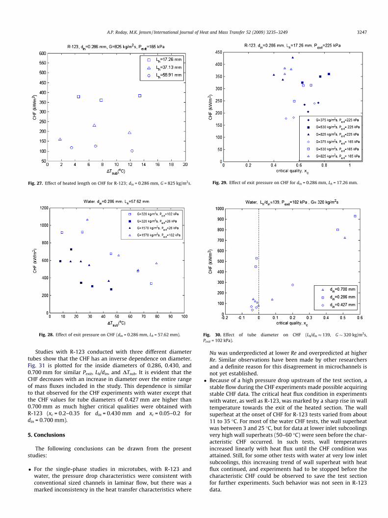
Fig. 27. Effect of heated length on CHF for R-123; din = 0.286 mm, G = 825 kg/m2s.
Fig. 28. Effect of exit pressure on CHF (din = 0.286 mm, Lh = 57.62 mm).
Fig. 29. Effect of exit pressure on CHF for din = 0.286 mm, Lh = 17.26 mm.
Fig. 30. Effect of tube diameter on CHF (Lh/din � 139, G � 320 kg/m2s,Pexit = 102 kPa).
A.P. Roday, M.K. Jensen / International Journal of Heat and Mass Transfer 52 (2009) 3235–3249 3247
Studies with R-123 conducted with three different diametertubes show that the CHF has an inverse dependence on diameter.Fig. 31 is plotted for the inside diameters of 0.286, 0.430, and0.700 mm for similar Pexit, Lh/din, and DTsub. It is evident that theCHF decreases with an increase in diameter over the entire rangeof mass fluxes included in the study. This dependence is similarto that observed for the CHF experiments with water except thatthe CHF values for tube diameters of 0.427 mm are higher than0.700 mm as much higher critical qualities were obtained withR-123 (xc = 0.2–0.35 for din = 0.430 mm and xc = 0.05–0.2 fordin = 0.700 mm).
5. Conclusions
The following conclusions can be drawn from the presentstudies:
� For the single-phase studies in microtubes, with R-123 andwater, the pressure drop characteristics were consistent withconventional sized channels in laminar flow, but there was amarked inconsistency in the heat transfer characteristics where
Nu was underpredicted at lower Re and overpredicted at higherRe. Similar observations have been made by other researchersand a definite reason for this disagreement in microchannels isnot yet established.
� Because of a high pressure drop upstream of the test section, astable flow during the CHF experiments made possible acquiringstable CHF data. The critical heat flux condition in experimentswith water, as well as R-123, was marked by a sharp rise in walltemperature towards the exit of the heated section. The wallsuperheat at the onset of CHF for R-123 tests varied from about11 to 35 �C. For most of the water CHF tests, the wall superheatwas between 3 and 25 �C, but for data at lower inlet subcoolingsvery high wall superheats (50–60 �C) were seen before the char-acteristic CHF occurred. In such tests, wall temperaturesincreased linearly with heat flux until the CHF condition wasattained. Still, for some other tests with water at very low inletsubcoolings, this increasing trend of wall superheat with heatflux continued, and experiments had to be stopped before thecharacteristic CHF could be observed to save the test sectionfor further experiments. Such behavior was not seen in R-123data.

Fig. 31. Effect of diameter on CHF for R-123.
3248 A.P. Roday, M.K. Jensen / International Journal of Heat and Mass Transfer 52 (2009) 3235–3249
In microchannels, at higher vapor qualities it is likely that a sta-ble vapor core is established (bubble grows to the channel size veryquickly), typical bubbly flow is suppressed, and evaporation at theliquid film vapor core is the dominant heat transfer mechanism.Such flow pattern has been observed by Thome et al. and couldbe a possible reason for wall temperatures to increase linearly withheat flux from single-phase region until the CHF, and the typicalchange in slope of DTsat versus q00 during boiling (boiling plateau)is suppressed. Jiang et al. had observed such wall temperaturebehaviors as well. In the present study, with water and R-123, sim-ilar wall temperature response with heat flux (linearly increasing)is more pronounced in experiments conducted with very low inletsubcoolings.
The data from this study were mapped using the flow patternmaps developed by Hassan et al. and by Revellin and Thome formicrotubes. Most of the water CHF data lie in the churn, churn–annular transition and annular regions close to the transitionwhereas the R-123 data are in the slug, slug–annular and annularregions. The data for water have high superficial liquid velocitiesand, hence, likely to exhibit a churn type behavior as opposed tothe slug behavior in the R-123 data.
From the extensive experiments conducted in this study, it isseen that flow patterns have a strong influence on the way differ-ent operating parameters affect the CHF condition. Previous stud-ies on CHF have not thoroughly investigated the effect of thedifferent operating parameters. Such parametric effects on CHFwere analyzed in this study for water and R-123, and the followingobservations were made:
� The increasing trend of CHF with mass flux is in general agree-ment with other researchers on CHF in microchannels. In thepresent data, for saturated conditions, the CHF is found toincrease with mass flux at fixed exit quality and is contraryto that found in conventional sized tubes. In conventionalsized tubes, increasing mass flux increases the CHF in the sub-cooled region because of increased convective effects,whereas in the saturated region, increasing the mass fluxdecreases the CHF at a given quality. This is a result ofincreased entrainment which accompanies increasing massflux in the annular flow regime. The data here similarly showan increasing trend of CHF with mass flux for a fixed value ofinlet subcooling in the subcooled region and also have thesame trend in the saturated region (refer to the sub-sectionon the effect of exit quality on CHF). This might indicate that
the flow regime in not ‘‘fully” annular in the sense thatentrainment in the vapor core is not too significant. Such com-parisons of mass flux effects at fixed exit quality in the satura-tion region have not been done by other researchers. Thiscontrary behavior could be because the data are taken forcomparatively lower mass fluxes and pressures than are avail-able for large-sized tubes. In this study, two types of flow pat-terns, churn and annular, exist in positive quality CHFconditions. The slug type of flow pattern during R-123 testsshows mainly subcooled CHF behavior. It is possible that thewavy interface during churn flow is more stable at highervapor velocities (for the same quality) leading to an increasein CHF with mass flux. Also, for the CHF data with annularflow, since such flows are triggered at lower heat fluxes, itcould be likely that initially large amount of droplets are bro-ken off into vapor core and as flow advances, the liquid drop-lets get deposited back on the liquid film increasing itsthickness, and this rate of deposition could be higher forhigher mass flux at the same quality inducing higher CHFvalues.� The data exhibit a complex behavior of CHF with exit qual-
ity. For the experiments conducted with water most of thedata are in the subcooled region with some being in the sat-urated region. The CHF decreased with an increase in qualityin the subcooled region, but as qualities approached zero,this trend was reversed, and the CHF increased with qualityinto the saturated region. Similar findings were reported byNariai et al. and Bergles et al. in minitubes.
Based on the data obtained in this study, Part II of the paper willdeal with the comparison of the data with the existing CHF corre-lations (micro/macrochannels). A new correlation will be proposedto predict CHF based on the trends obtained in this study. Also, theunique behavior of the CHF with exit quality will be looked into de-tail to see if the point of net vapor generation (PNVG) could be oneof the transition points for the change in behavior from the sub-cooled to the saturated region.
Acknowledgments
The support of the National Science Foundation with Grant No.CTS 0245642 and of Rensselaer Polytechnic Institute is gratefullyacknowledged. This work is supported in part by the Office of Na-val Research (ONR) under the Multidisciplinary University Re-search Initiative (MURI) Award GG10919.
References
[1] S. Kakac, H. Liu, Heat Exchangers: Selection, Rating and Thermal Design, CRCPress, 1998. pp. 903–904 (Chapter 9).
[2] C.L. Vandervort, A.E. Bergles, M.K. Jensen, An experimental study of criticalheat flux in very high heat flux subcooled boiling, Int. J. Heat Mass Transfer 37(Suppl. 1) (1994) 161–173.
[3] G.P. Celata, M. Cumo, A. Mariani, Burnout in highly subcooled water flowboiling in small diameter tubes, Int. J. Heat Mass Transfer 36 (1993) 1269–1285.
[4] G.P. Celata, M. Cumo, A. Mariani, Geometrical effects on the subcooled flowboiling critical heat flux, Rev. Générale Thermique 36 (1997) 807–814.
[5] H. Nariai, F. Inasaka, K. Uehara, Critical heat flux in narrow tubes with uniformheating, Trans. Jpn. Soc. Mech. Eng. 54 (1988) 1406–1410.
[6] A.E. Bergles, W.M. Rohsenow, Forced-convection surface-boiling heat transferand burnout in tubes of small diameter, Contract AF 19(604)-7344 Report,Department of Mechanical Engineering, Massachusetts Institute ofTechnology, 1962.
[7] G.M. Roach Jr., S.I. Abdel-Khalik, S.M. Ghiaasiaan, M.F. Dowling, S.M. Jeter, Lowflow critical heat flux in heated microchannels, Nucl. Sci. Eng. 131 (1999) 411–425.
[8] G.M. Lazarek, S.H. Black, Evaporative heat transfer, pressure drop and criticalheat flux in a small vertical tube with R-113, Int. J. Heat Mass Transfer 25(1982) 945–960.

A.P. Roday, M.K. Jensen / International Journal of Heat and Mass Transfer 52 (2009) 3235–3249 3249
[9] W. Qu, I. Mudawar, Measurement and correlation of critical heat flux in two-phase micro-channel heat sinks, Int. J. Heat Mass Transfer 47 (2004) 2045–2059.
[10] W. Yu, D.M. France, M.W. Wambsganss, J.R. Hull, Two-phase pressure drop,boiling heat transfer, and critical heat flux to water in a small-diameterhorizontal tube, Int. J. Multiphase Flow 28 (2002) 927–941.
[11] A.M. Lezzi, A. Niro, G.P. Beretta, Experimental data on CHF for forced convectionwater boiling in long horizontal capillary tubes, in: Proceedings of the 10thInternational Heat Transfer Conference, vol. 7, Rugby, UK, 1994, pp. 491–496.
[12] L. Jiang, M. Wong, Y. Zohar, Phase change in microchannel heat sinks withintegrated temperature sensors, J. Microelectromech. Syst. 8 (1999) 358–365.
[13] L. Wojtan, R. Revellin, J.R. Thome, Investigation of saturated critical heat flux in asingle uniformly heated microchannel, Exp. Thermal Fluid Sci. 30 (2006) 765–774.
[14] A.P. Roday, T. Borca-Tasçiuc, M.K. Jensen, The critical heat flux condition withwater in a uniformly heated microtube, J. Heat Transfer 130 (2008) 012901-1–012901-10.
[15] A.E. Bergles, S.G. Kandlikar, On the nature of critical heat flux in microchannels,J. Heat Transfer 127 (2005) 101–107.
[16] A. Kos�ar, C.-J. Kuo, Y. Peles, Suppression of boiling flow oscillations in parallelmicrochannels by inlet restrictors, J. Heat Transfer 128 (2006) 251–260.
[17] A. Kos�ar, Y. Peles, Critical heat flux of R-123 in silicon-based microchannels, J.Heat Transfer 129 (2007) 844–851.
[18] W.K. Kuan, S.G. Kandlikar, Critical heat flux measurement and model forefrigerant-123 under stabilized flow conditions in microchannels, in:Proceedings of IMECE 2006, IMECE2006-13310, 2006 ASME InternationalMechanical Engineering Congress and Exposition, Chicago, IL, USA, November5–10, 2006.
[19] C.H. Oh, S.B. Englert, Critical heat flux for low flow boiling in vertical uniformlyheated thin rectangular channels, Int. J. Heat Mass Transfer 36 (1993) 325–335.
[20] M.B. Bowers, I. Mudawar, High flux boiling in low flow rate, low pressure dropmini-channel and micro-channel heat sinks, Int. J. Heat Mass Transfer 37(1994) 321–332.
[21] S.J. Kline, F.A. McClintock, Describing uncertainties in single sampleexperiments, Mech. Eng. 75 (1953) 3–8.
[22] A.P. Roday, Study of the critical heat flux condition in microtubes, Ph.D. thesis,Rensselaer Polytechnic Institute, Troy, NY, 2007.
[23] G.P. Celata, M. Cumo, M. Guglielmi, G. Zummo, Experimental investigation ofhydraulic and single-phase heat transfer in 0.13-mm capillary tube, MicroscaleThermophys. Eng. 6 (2002) 85–97.
[24] X.F. Peng, G.P. Peterson, Convective heat transfer and flow friction for waterflow in microchannel structures, Int. J. Heat Mass Transfer 39 (1996) 2599–2608.
[25] G.P. Celata, N. Ksagi, Preface, Int. J. Heat Fluid Flow 28 (2007) 1.[26] A. Kos�ar, C.-J. Kuo, Y. Peles, Reduced pressure boiling heat transfer in
rectangular microchannels with interconnected reentrant cavities, J. HeatTransfer 127 (2005) 1106–1114.
[27] A.E. Bergles, R.F. Lopina, M.P. Fiori, Critical-heat-flux and flow-patternobservations for low-pressure water flowing in tubes, J. Heat Transfer (1967)69–74.
[28] I. Hasaan, M. Vaillancourt, K. Pehlivan, Two-phase flow regime transitions inmicrochannels: a comparative experimental study, Microscale Thermophys.Eng. 9 (2005) 165–182.
[29] R. Revellin, J.R. Thome, A new type of diabatic flow pattern map for boilingheat transfer in microchannels, J. Micromech. Microeng. 17 (2007) 788–796.