international iso standard 13007-4 - official site · iso 4200, plain end steel tubes, welded and...
TRANSCRIPT

Reference numberISO 13007-4:2005(E)
© ISO 2005
INTERNATIONAL STANDARD
ISO13007-4
First edition2005-09-15
Ceramic tiles — Grouts and adhesives —Part 4: Test methods for grouts
Carreaux céramiques — Mortiers de joints et colles —
Partie 4: Méthodes d'essai pour les mortiers de joints
Licensed to MAPEI SPA/MAPEI SPA MAPEI SPAISO Store order #: 694255/Downloaded: 2005-09-21Single user licence only, copying and networking prohibited

ISO 13007-4:2005(E)
PDF disclaimer This PDF file may contain embedded typefaces. In accordance with Adobe's licensing policy, this file may be printed or viewed but shall not be edited unless the typefaces which are embedded are licensed to and installed on the computer performing the editing. In downloading this file, parties accept therein the responsibility of not infringing Adobe's licensing policy. The ISO Central Secretariat accepts no liability in this area.
Adobe is a trademark of Adobe Systems Incorporated.
Details of the software products used to create this PDF file can be found in the General Info relative to the file; the PDF-creation parameters were optimized for printing. Every care has been taken to ensure that the file is suitable for use by ISO member bodies. In the unlikely event that a problem relating to it is found, please inform the Central Secretariat at the address given below.
© ISO 2005 All rights reserved. Unless otherwise specified, no part of this publication may be reproduced or utilized in any form or by any means, electronic or mechanical, including photocopying and microfilm, without permission in writing from either ISO at the address below or ISO's member body in the country of the requester.
ISO copyright office Case postale 56 • CH-1211 Geneva 20 Tel. + 41 22 749 01 11 Fax + 41 22 749 09 47 E-mail [email protected] Web www.iso.org
Published in Switzerland
ii © ISO 2005 – All rights reserved
Licensed to MAPEI SPA/MAPEI SPA MAPEI SPAISO Store order #: 694255/Downloaded: 2005-09-21Single user licence only, copying and networking prohibited
ISO 13007-4:2005(E)
© ISO 2005 – All rights reserved iii
Contents Page
Foreword............................................................................................................................................................ iv 1 Scope ..................................................................................................................................................... 1 2 Normative references ........................................................................................................................... 1 3 General test conditions and procedures............................................................................................ 2 3.1 Sampling................................................................................................................................................ 2 3.2 Test conditions ..................................................................................................................................... 2 3.3 Test materials........................................................................................................................................ 2 3.4 Mixing procedures ................................................................................................................................ 2 3.5 Test report ............................................................................................................................................. 3 4 Test methods......................................................................................................................................... 3 4.1 Determination of flexural and compressive strength ....................................................................... 3 4.2 Determination of water absorption ..................................................................................................... 6 4.3 Determination of shrinkage ................................................................................................................. 7 4.4 Determination of resistance to abrasion............................................................................................ 9 4.5 Determination of transverse deformation ........................................................................................ 11 4.6 Determination of chemical resistance.............................................................................................. 11 Annex A (normative) Requirements for test apparatus ............................................................................... 21 Bibliography ..................................................................................................................................................... 25
Licensed to MAPEI SPA/MAPEI SPA MAPEI SPAISO Store order #: 694255/Downloaded: 2005-09-21Single user licence only, copying and networking prohibited
ISO 13007-4:2005(E)
iv © ISO 2005 – All rights reserved
Foreword
ISO (the International Organization for Standardization) is a worldwide federation of national standards bodies (ISO member bodies). The work of preparing International Standards is normally carried out through ISO technical committees. Each member body interested in a subject for which a technical committee has been established has the right to be represented on that committee. International organizations, governmental and non-governmental, in liaison with ISO, also take part in the work. ISO collaborates closely with the International Electrotechnical Commission (IEC) on all matters of electrotechnical standardization.
International Standards are drafted in accordance with the rules given in the ISO/IEC Directives, Part 2.
The main task of technical committees is to prepare International Standards. Draft International Standards adopted by the technical committees are circulated to the member bodies for voting. Publication as an International Standard requires approval by at least 75 % of the member bodies casting a vote.
Attention is drawn to the possibility that some of the elements of this document may be the subject of patent rights. ISO shall not be held responsible for identifying any or all such patent rights.
ISO 13007-4 was prepared by Technical Committee ISO/TC 189, Ceramic Tile.
ISO 13007 consists of the following parts, under the general title Ceramic Tiles — Grouts and adhesives:
Part 1: Terms, definitions and specifications for adhesives
Part 2: Test methods for adhesives
Part 3: Terms, definitions and specifications for grouts
Part 4: Test methods for grouts
Licensed to MAPEI SPA/MAPEI SPA MAPEI SPAISO Store order #: 694255/Downloaded: 2005-09-21Single user licence only, copying and networking prohibited
INTERNATIONAL STANDARD ISO 13007-4:2005(E)
© ISO 2005 – All rights reserved 1
Ceramic tiles — Grouts and adhesives —
Part 4: Test methods for grouts
1 Scope
This part of ISO 13007 specifies methods for determining characteristics for grouts used in the installation of ceramic tiles.
The following test methods are described:
determination of flexural and compressive strength (4.1);
determination of water absorption (4.2);
determination of shrinkage (4.3);
determination of resistance to abrasion (4.4);
determination of transverse deformation (4.5);
determination of chemical resistance (4.6).
2 Normative references
The following referenced documents are indispensable for the application of this document. For dated references, only the edition cited applies. For undated references, the latest edition of the referenced document (including any amendments) applies.
ISO 409-1, Metallic materials — Hardness test —Tables of Vickers hardness values for use in tests made on flat surfaces — Part 1: HV 5 to HV 100
ISO 630, Structural steels — Plates, wide flats, bars, sections and profiles
ISO 1101, Geometrical Product Specifications (GPS) — Geometrical tolerancing — Tolerances of form, orientation, location and run-out
ISO 1302, Geometrical Product Specifications (GPS) — Indication of surface texture in technical product documentation
ISO 4200, Plain end steel tubes, welded and seamless — General tables of dimensions and masses per unit length
ISO 8486-1, Bonded abrasives — Determination and designation of grain size distribution — Part 1: Macrogrits F4 to F220
ISO 13007-2:2005, Ceramic tiles — Grouts and adhesives — Part 2: Test methods for adhesives
Licensed to MAPEI SPA/MAPEI SPA MAPEI SPAISO Store order #: 694255/Downloaded: 2005-09-21Single user licence only, copying and networking prohibited

ISO 13007-4:2005(E)
2 © ISO 2005 – All rights reserved
3 General test conditions and procedures
3.1 Sampling
A representative sample of at least 2 kg shall be used.
3.2 Test conditions
Standard conditions shall be (23 ± 2) °C and (50 ± 5) % relative humidity and a circulation of air in the testing area less than 0,2 m/s. Other test conditions may be specified in Clause 4. The tolerance in the time of conditioning for all test specimens shall be as follows:
Conditioning Tolerance
24 h ± 0,5 h
7 days ± 3 h
14 days ± 6 h
21 days ± 9 h
28 days ± 12 h
3.3 Test materials
Condition all test materials including water for at least 24 h under standard conditions. The grout to be tested shall be within its shelf life, where this is specified.
3.4 Mixing procedures
3.4.1 Cementitious grouts (CG)
The amount of water and/or liquid admix required for preparing the grout shall be as stated by the manufacturer in parts by weight, i.e. liquid to dry powder (in the case where a range of values is given, the average shall be used).
Prepare a minimum quantity of 2 kg of the powder and the necessary liquid using a mixer of the planetary type (see ISO 13007-2:2005, Figures 1 and 2), running at the slow speed settings (140 ± 5) rev/min and (62 ± 5) rev/min planetary movement.
Carry out the following procedure:
pour the liquid into the pan;
scatter the dry powder over the liquid;
mix for 30 s;
take out the mixing paddle;
scrape down the paddle and pan within 1 min;
replace the paddle and mix for 1 min.
If required by the grout manufacturer’s instructions, let the grout mature as specified and then mix for an additional 15 s.
Licensed to MAPEI SPA/MAPEI SPA MAPEI SPAISO Store order #: 694255/Downloaded: 2005-09-21Single user licence only, copying and networking prohibited

ISO 13007-4:2005(E)
© ISO 2005 – All rights reserved 3
3.4.2 Reaction resin grouts (RG)
Where reaction resin grouts are to be used, the manufacturer’s instructions shall be followed.
3.5 Test report
The following information shall be provided in the test report:
a) reference to this part of ISO 13007, i.e. “ISO 13007-4”;
b) date of test;
c) type of grout, commercial designation and manufacturer's name;
d) source, date obtained and complete identification of test sample;
e) handling and storage of samples before testing;
f) test conditions;
g) amount of water or liquid used for preparing grout;
h) test results (individual and mean values and mode of failure where required);
i) any other factor that could have affected the result.
4 Test methods
4.1 Determination of flexural and compressive strength
Flexural and compressive strength shall be tested following the general test conditions and procedures given in Clause 3 and the specific instructions which follow.
4.1.1 Apparatus
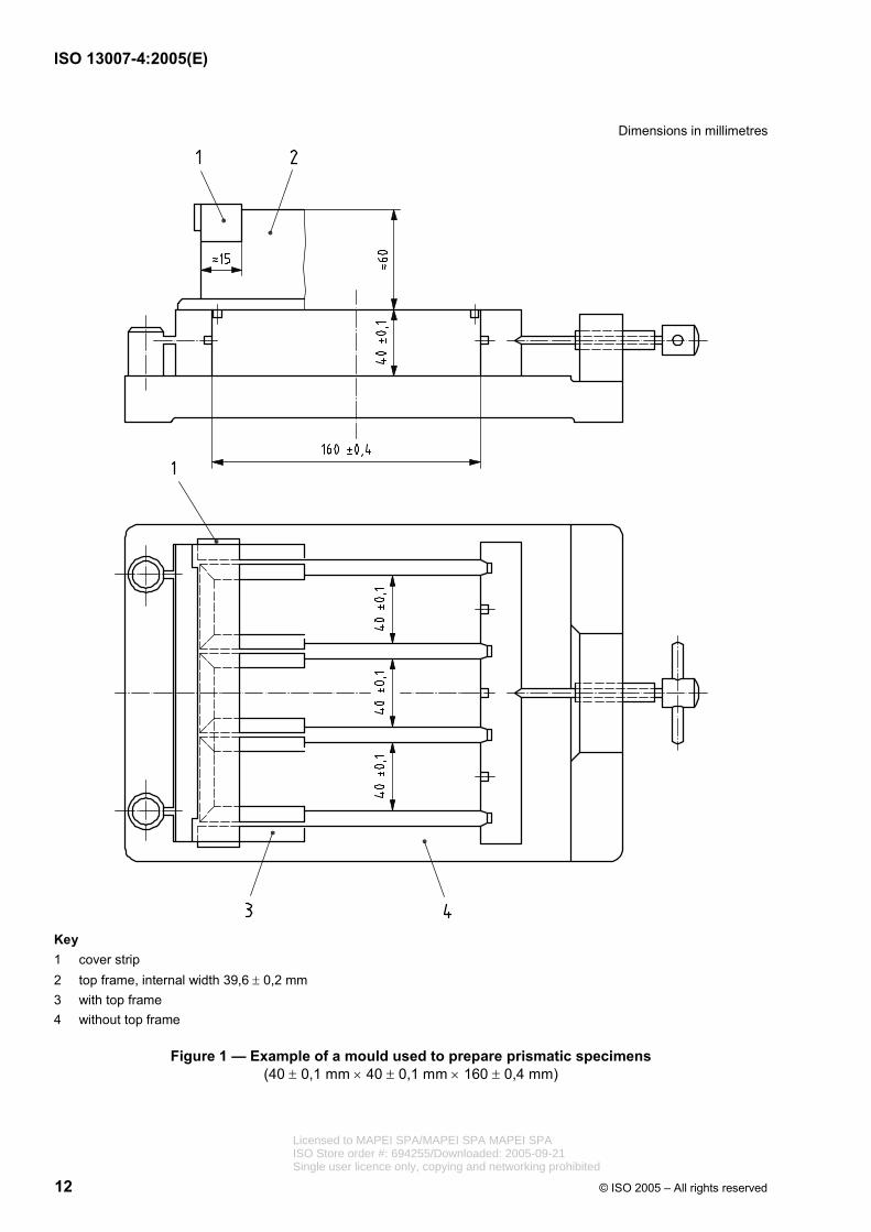
4.1.1.1 Gang moulds, three gang moulds used to prepare prismatic specimens (40 ± 0,1) mm × (40 ± 0,1) mm × (160 ± 0,4) mm, with ground surfaces, made of steel.
Holes for fitting suitable pins shall be pierced into the sides of the moulds corresponding to the ends of test specimen (see Figure 1).
4.1.1.2 Jolting apparatus or jolting table, used for the settlement of 40 mm × 40 mm × 160 mm grout specimen in accordance with Figure 2.
4.1.1.3 Testing machine.
The testing machine shall be capable of applying the load with suitable capacity and sensitivity for the test. The machine shall be provided with a flexure device in accordance with Figure 3.
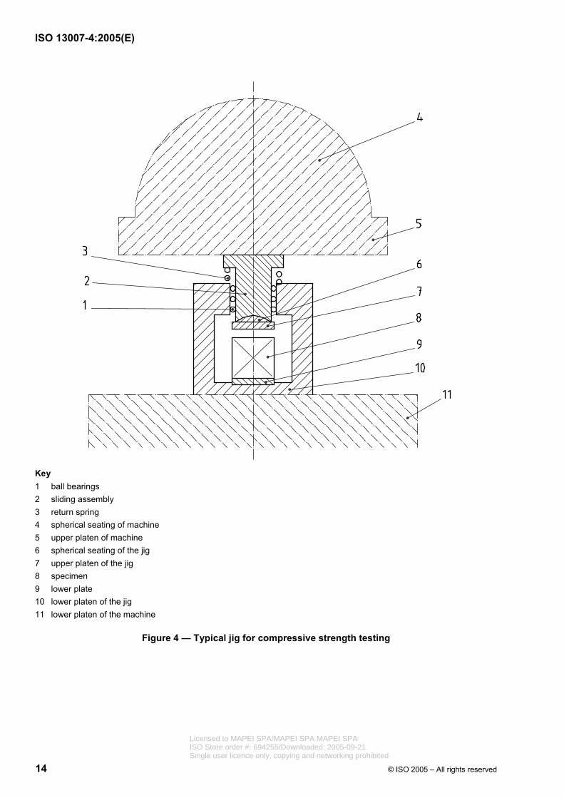
4.1.1.4 Testing jig.
The compressive strength test requires the use of a jig, in accordance with Figure 4, to be incorporated in the lower platen; the upper platen receives the load from the compressive strength testing machine through an intermediate spherical seating.
Licensed to MAPEI SPA/MAPEI SPA MAPEI SPAISO Store order #: 694255/Downloaded: 2005-09-21Single user licence only, copying and networking prohibited

ISO 13007-4:2005(E)
4 © ISO 2005 – All rights reserved
4.1.2 Preparation of test units
Mould the specimens immediately after the mixing of the grout, with the mould firmly clamped to the jolting table.
Introduce, using a suitable scoop, the first of two layers of grout into each of the compartments, directly from the mixing bowl.
Spread the layer uniformly, then compact using 60 jolts.
Introduce the second layer of grout, level and compact with a further 60 jolts.
Prepare three specimens for each grout.
Lift the mould gently from the jolting table, strike off excess of material and smooth the surface with a flat trowel.
Wipe off the grout left on the perimeter of the mould.
Place a 210 mm × 185 mm plate glass sheet of 6 mm thickness on the mould. A plate of steel or other impermeable material of similar size may be used.
Place the mould, suitably identified, on a horizontal base in standard conditions, (23 ± 2) °C and (50 ± 5) % R.H.
After 24 h, carefully remove the specimen from the mould.
Prepare three specimens for each grout.
For fast setting grout, demould the specimen immediately before the test.
4.1.3 Flexural strength under standard conditions
Keep the demoulded prism in standard conditions for 27 days, leaving a clearance between prisms of at least 25 mm.
After conditioning has been completed, place the prism in the testing machine (4.1.1.3) with one side face on the supporting rollers and with the longitudinal axis normal to the support.
Apply the load vertically by means of the loading roller to the opposite side face of the prism, and increase it smoothly at the rate of (50 ± 10) N/s until fracture.
Keep the prism halves in standard conditions until tested in compression.
4.1.4 Compressive strength under standard conditions
Test the prism halves broken in flexion, by means of the equipment specified in 4.1.1.4.
Centre the prism halves laterally to the platens of the machine within ± 0,5 mm, and longitudinally such that the end face of the prism overhangs the platens or auxiliary plates by about 10 mm.
Increase the load smoothly at the rate of (2 400 ± 200) N/s over the entire load application until fracture.
4.1.5 Flexural and compressive strength after freeze-thaw cycles
Prepare the test units in accordance with 4.1.2.
Licensed to MAPEI SPA/MAPEI SPA MAPEI SPAISO Store order #: 694255/Downloaded: 2005-09-21Single user licence only, copying and networking prohibited
ISO 13007-4:2005(E)
© ISO 2005 – All rights reserved 5
Condition the test units for 6 days in standard conditions, and then immerse in water for 21 days before carrying out 25 freeze-thaw cycles, following the procedure given in 4.4.4.5 of ISO 13007-2.
Condition the test units for 3 days in standard conditions after the last cycle, and prior to test, examine them and record a brief description of surface appearance of the specimen.
Determine the flexural strength in accordance with 4.1.3 and the compressive strength in accordance with 4.1.4
4.1.6 Evaluation of results
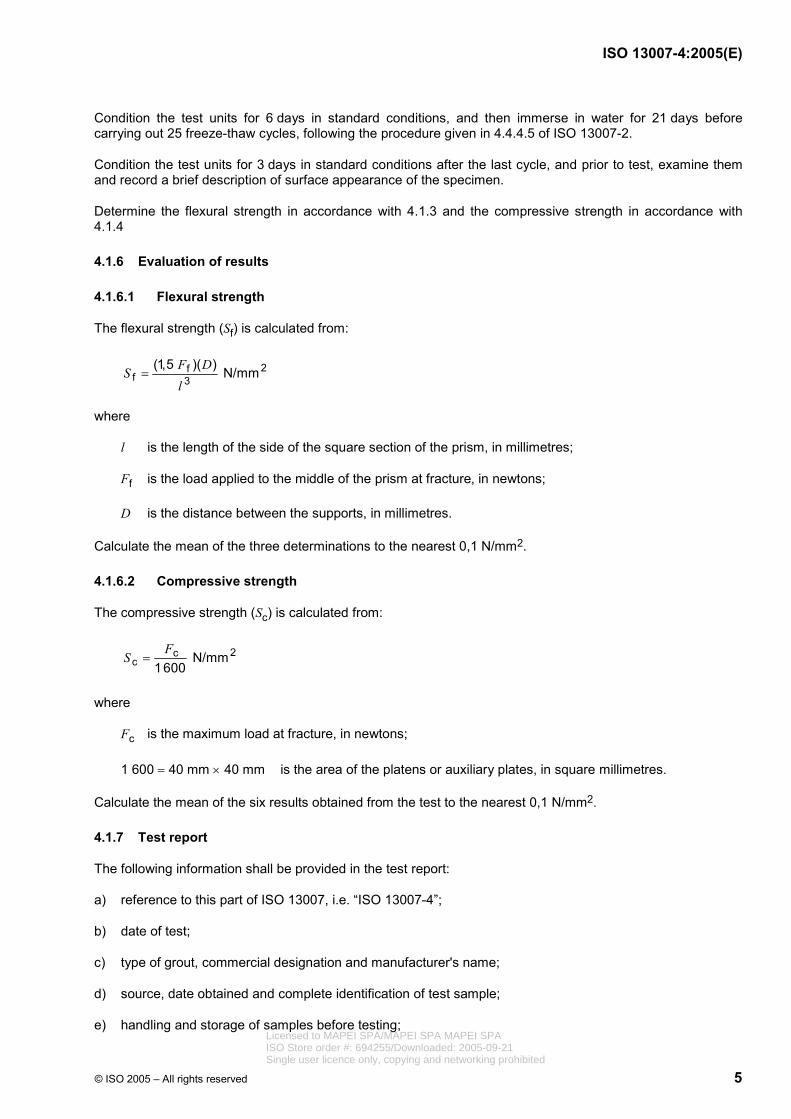
4.1.6.1 Flexural strength
The flexural strength (Sf) is calculated from:
2ff 3
(1,5 )( ) N/mmF DSl
=
where
l is the length of the side of the square section of the prism, in millimetres;
Ff is the load applied to the middle of the prism at fracture, in newtons;
D is the distance between the supports, in millimetres.
Calculate the mean of the three determinations to the nearest 0,1 N/mm2.
4.1.6.2 Compressive strength
The compressive strength (Sc) is calculated from:
2cc
N/mm
1600F
S =
where
Fc is the maximum load at fracture, in newtons;
1 600 = 40 mm × 40 mm is the area of the platens or auxiliary plates, in square millimetres.
Calculate the mean of the six results obtained from the test to the nearest 0,1 N/mm2.
4.1.7 Test report
The following information shall be provided in the test report:
a) reference to this part of ISO 13007, i.e. “ISO 13007-4”;
b) date of test;
c) type of grout, commercial designation and manufacturer's name;
d) source, date obtained and complete identification of test sample;
e) handling and storage of samples before testing; Licensed to MAPEI SPA/MAPEI SPA MAPEI SPAISO Store order #: 694255/Downloaded: 2005-09-21Single user licence only, copying and networking prohibited
ISO 13007-4:2005(E)
6 © ISO 2005 – All rights reserved
f) test conditions;
g) amount of water or liquid used for preparing grout;
h) test results (individual and mean values and mode of failure where required);
i) any other factor that could have affected the result;
j) results of visual inspection of each specimen before and after testing, with test results individual and mean values for each condition in newtons per square millimetre;
4.2 Determination of water absorption
4.2.1 General
Water absorption shall be tested following the general test conditions and procedures given in Clause 3 and the specific instructions which follow.
4.2.2 Apparatus
4.2.2.1 Gang moulds, three gang moulds as described in 4.1.1.1.
4.2.2.2 Inserts, three, 1 mm thick of rigid plastic (e.g. PTFE) or HDPE with no release agent.
4.2.2.3 Jolting apparatus or jolting table, as described in 4.1.1.2.
4.2.2.4 Tray, with a flat base large enough to contain three test specimens.
4.2.3 Preparation of test samples
Place the inserts approximately in the middle of the mould, parallel to the smaller faces. Following the procedure described in 4.1.2, prepare six specimens of each grout. After demoulding, condition the samples for 20 days in standard conditions. Seal the four sides with dimension 40 mm by 80 mm by means of a neutral curing silicone sealant so as to be water impermeable. Then condition the samples for 7 additional days.
4.2.4 Test procedure
Twenty eight days after mixing, weigh each test sample to the nearest 0,01 g and then place them vertically in the tray, with the unsealed surface down on round or triangular spacers with dimension 40 mm by 40 mm, immersed in water, 5 mm to 10 mm deep, taking care to prevent the prism faces from coming in contact with each other.
Maintain the water level constant by adding water when necessary.
After 30 min, remove the test samples from water, quickly dry them by blotting with a dampened cloth and immediately weigh.
Replace in the tray and repeat the procedure after an additional 210 min.
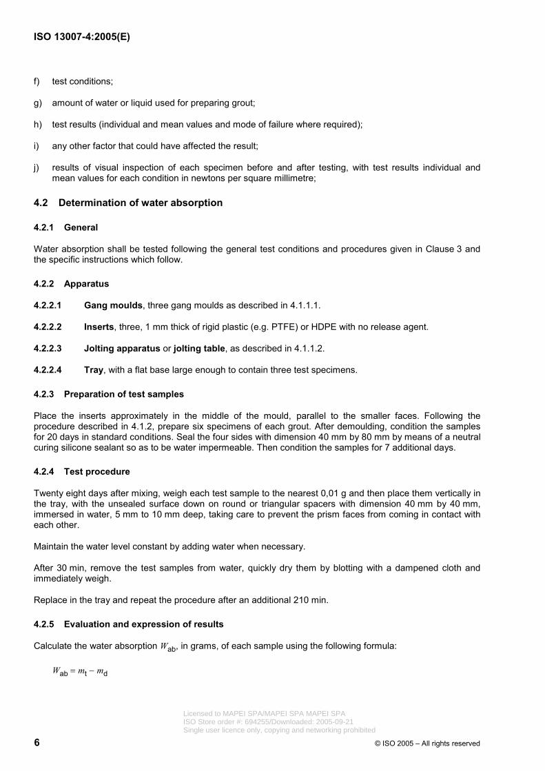
4.2.5 Evaluation and expression of results
Calculate the water absorption Wab, in grams, of each sample using the following formula:
Wab = mt − md
Licensed to MAPEI SPA/MAPEI SPA MAPEI SPAISO Store order #: 694255/Downloaded: 2005-09-21Single user licence only, copying and networking prohibited

ISO 13007-4:2005(E)
© ISO 2005 – All rights reserved 7
where
md is the mass of the dry specimen, in grams;
mw is the mass of the specimen after immersion, in grams.
Calculate the mean of at least three test samples.
4.2.6 Test report
The following information shall be provided in the test report:
a) reference to this part of ISO 13007, i.e. “ISO 13007-4”;
b) date of test;
c) type of grout, commercial designation and manufacturer's name;
d) source, date obtained and complete identification of test sample;
e) handling and storage of samples before testing;
f) test conditions;
g) amount of water or liquid used for preparing grout;
h) test results (individual and mean values and mode of failure where required);
i) any other factor that could have affected the result;
j) test results expressed as individual and mean values after 30 min and 240 min.
4.3 Determination of shrinkage
4.3.1 General
Shrinkage shall be tested following the general test conditions and procedures given in Clause 3 and the specific instructions which follow.
4.3.2 Apparatus
4.3.2.1 Gang moulds, three gang moulds with optional inserts as described in 4.1.1.1.
4.3.2.2 Inserts, six smooth inserts: rigid, non-absorbent frames (e.g. in polyethylene or PTFE), with dimensions of (40 ± 0,1 × 160 ± 0,4) mm and thickness of (15 ± 0,1) mm.
4.3.2.3 Jolting apparatus, as described in Figure 2.
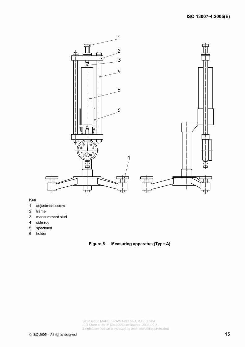
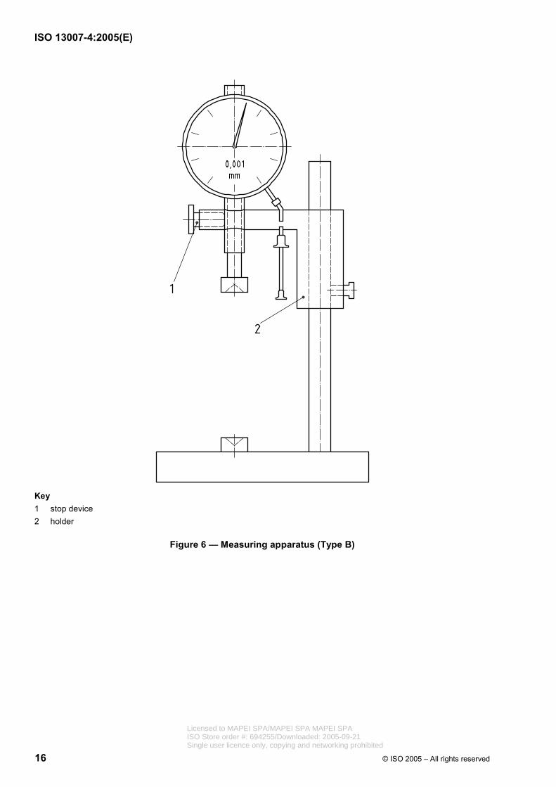
4.3.2.4 Measuring apparatus.
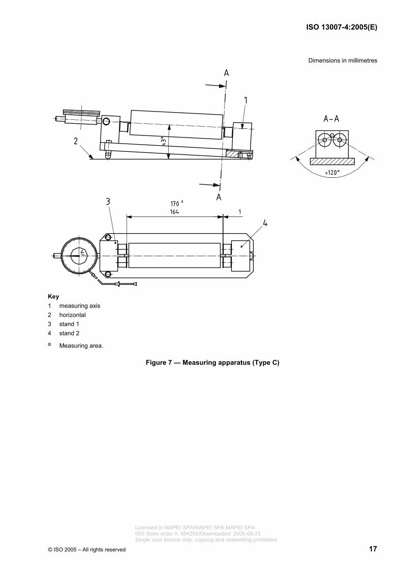
Measuring apparatus shall consist of a measurement attachment and a base with adjustment screws. The measurement attachment shall be formed by a dial gauge, which reads accurately to 0,01 mm, rigidly mounted in a measuring frame (see Figures 5, 6 and 7).
4.3.2.5 Calibration rod.
Calibration rod or reference rod shall be used as a standard length against which gauge readings can be tested. The rod shall be made of material having a negligible coefficient of expansion (e.g. Invar).
Licensed to MAPEI SPA/MAPEI SPA MAPEI SPAISO Store order #: 694255/Downloaded: 2005-09-21Single user licence only, copying and networking prohibited
ISO 13007-4:2005(E)
8 © ISO 2005 – All rights reserved
4.3.3 Preparation of test samples
Assemble suitable mould to prepare samples.
Mould the specimens immediately after the mixing of the grout, with the mould firmly clamped to the jolting table. Introduce, using a suitable scoop, the first of two layers of grout into each of the compartments, directly from the mixing bowl.
Spread the layer uniformly, then compact using 60 jolts.
Introduce the second layer of grout, level and compact with a further 60 jolts.
Lift the mould gently from the jolting table, strike off excess material and smooth the surface with a flat trowel.
Wipe off the grout left on the perimeter of the mould.
Cover with a glass plate according to 4.1.2.
Place the mould, suitably identified, on a horizontal base in standard conditions, (23 ± 2°) °C and (50 ± 5) % R.H.
After 24 h, carefully remove the specimens from the mould.
Prepare three specimens for each grout.
4.3.4 Test procedure
Immediately after demoulding determine the length of the test samples (initial reading) using the measuring apparatus (see 4.3.1.4).
Keep the demoulded prisms on a 10 mm dimension under standard conditions, leaving a clearance of at least 25 mm between specimens.
Take a reading of each specimen after 27 days ± 12 h from the initial reading.
4.3.5 Evaluation of results
The linear shrinkage is reported in millimetres per metre as the mean of three values based on the initial measurement.
4.3.6 Test report
The following information shall be provided in the test report:
a) reference to this part of ISO 13007, i.e. “ISO 13007-4”;
b) date of test;
c) type of grout, commercial designation and manufacturer's name;
d) source, date obtained and complete identification of test sample;
e) handling and storage of samples before testing;
f) test conditions;
g) amount of water or liquid used for preparing grout;
Licensed to MAPEI SPA/MAPEI SPA MAPEI SPAISO Store order #: 694255/Downloaded: 2005-09-21Single user licence only, copying and networking prohibited
ISO 13007-4:2005(E)
© ISO 2005 – All rights reserved 9
h) test results (individual and mean values and mode of failure where required);
i) any other factor that could have affected the result;
j) results of visual inspection of each specimen before and after testing, with test results individual and mean values for each condition in newtons per square millimetre;
k) test results (individual and mean values) in millimetres per metre
4.4 Determination of resistance to abrasion
4.4.1 General
Resistance to abrasion shall be tested following the general test conditions and procedures given in Clause 3, and the specific instructions which follow.
4.4.2 Apparatus
4.4.2.1 Abrasion apparatus, consisting essentially of a rotating disc, a storage hopper with a dispensing device for the abrasive material, a test specimen support and a counterweight (see Figure 8).
The disc is made of E 235 A (Fe 360 A) in accordance with ISO 630, with a diameter of (200 ± 0,2) mm and thickness at the edge of ten (10 ± 0,1) mm, and with a revolution rate of 75 rev/min. The pressure with which the test specimens are held against the steel disc is determined by calibrating the apparatus against transparent fused silica. The pressure is adjusted such that, after 150 revolutions using F 80 (ISO 8486-1) abrasive, a chord (24 ± 0,5) mm is produced. Transparent fused silica shall be used as a primary standard. A secondary standard of float glass or other products may be used. When the diameter has worn by 0,5 % of the initial diameter, the steel disc shall be replaced.
4.4.2.2 Abrasive material, white fused aluminium oxide of grain size 80 in accordance to ISO 8486-1.
4.4.2.3 Measuring gauge, accurate to 0,1 mm.
4.4.2.4 Template, a smooth, square, rigid, non absorbent frame (e.g. in polyethylene or PTFE), with internal dimensions of (100 ± 1) mm × (100 ± 1) mm and thickness of (10 ± 1) mm.
4.4.3 Preparation of test samples
The grout shall be prepared as described in Clause 3.
Place the template over a polyethylene film.
Trowel sufficient quantity of grout across the template, and then screed clean so as to neatly and completely fill the hole in the template.
Cover with a glass plate in accordance with 4.1.2.
After 24 h, carefully remove the template.
Condition the units according to the test requirements.
Prepare two specimens for each grout sample.
4.4.4 Test procedure
Place a test specimen in the apparatus (4.4.1.1) with the trowelled face against the disc so that it is tangential against the rotating disc.
Licensed to MAPEI SPA/MAPEI SPA MAPEI SPAISO Store order #: 694255/Downloaded: 2005-09-21Single user licence only, copying and networking prohibited

ISO 13007-4:2005(E)
10 © ISO 2005 – All rights reserved
Ensure that abrasive material (4.4.1.2) is fed uniformly into the grinding zone at a rate of (100 ± 10) g per 100 revolutions.
Rotate the steel disc for 50 revolutions.
Remove the test specimen from the apparatus and measure the chord length (L) of the groove to the nearest 0,5 mm.
Test each test specimen in at least two places at right angles to each other.
Do not re-use the abrasive material.
4.4.5 Expression of results
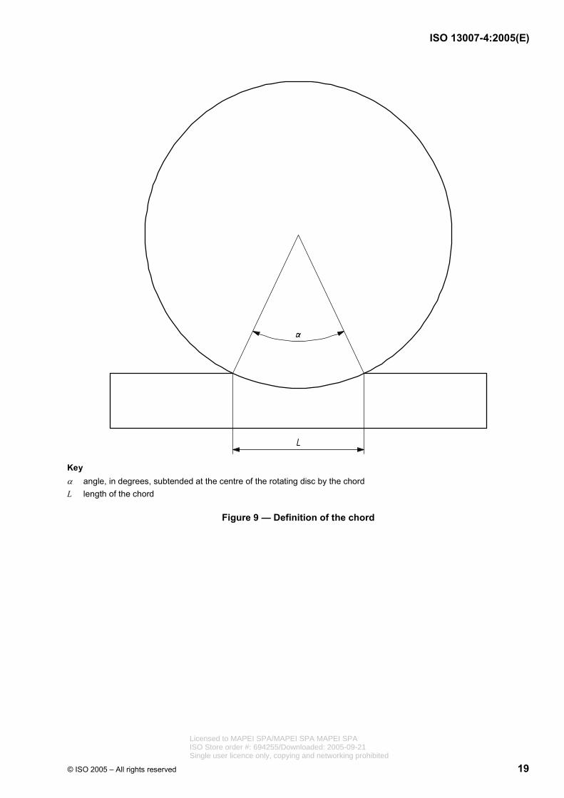
The resistance to deep abrasion is expressed as the volume V, in cubic millimetres, of material removed, and is calculated from the chord length (L) of the groove using the equation:
2sin
180 8hdV α απ = − ×
with
( )sin 0,5 Ld
α =
α is the angle, in degrees, subtended at the centre of the rotating disc by the chord (see Figure 9):
h is the thickness, in millimetres, of the rotating disc;
d is the diameter, in millimetres, of the rotating disc; and
L is the length, in millimetres, of the chord.
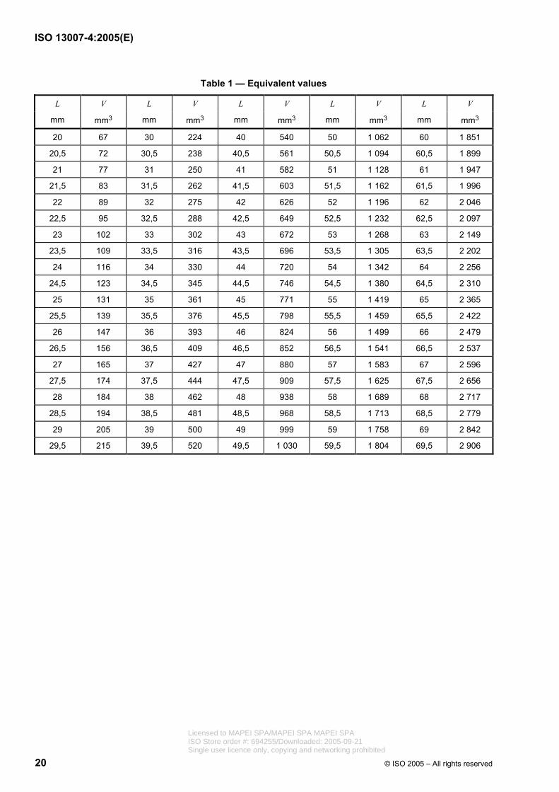
Some equivalent values of L and V are given in Table 1.
4.4.6 Test report
The following information shall be provided in the test report:
a) reference to this part of ISO 13007, i.e. “ISO 13007-4”;
b) date of test;
c) type of grout, commercial designation and manufacturer's name;
d) source, date obtained and complete identification of test sample;
e) handling and storage of samples before testing;
f) test conditions;
g) amount of water or liquid used for preparing grout;
h) test results (individual and mean values and mode of failure where required);
i) any other factor that could have affected the result;
Licensed to MAPEI SPA/MAPEI SPA MAPEI SPAISO Store order #: 694255/Downloaded: 2005-09-21Single user licence only, copying and networking prohibited
ISO 13007-4:2005(E)
© ISO 2005 – All rights reserved 11
j) results of visual inspection of each specimen before and after testing, with test results individual and mean values for each condition in newtons per square millimetre;
k) the chord length (L) of each groove to the nearest 0,5 mm;
l) the volume (V), in cubic millimetres, for each individual groove; and
m) the average volume (Vav) in cubic millimetres.
4.5 Determination of transverse deformation
Transverse deformation shall be tested and reported by following the procedures given in 4.5 of ISO 13007-2.
4.6 Determination of chemical resistance
Chemical resistance shall be tested and reported by following the procedures given in 4.6 of ISO 13007-2.
Licensed to MAPEI SPA/MAPEI SPA MAPEI SPAISO Store order #: 694255/Downloaded: 2005-09-21Single user licence only, copying and networking prohibited
ISO 13007-4:2005(E)
12 © ISO 2005 – All rights reserved
Dimensions in millimetres
Key 1 cover strip 2 top frame, internal width 39,6 ± 0,2 mm 3 with top frame 4 without top frame
Figure 1 — Example of a mould used to prepare prismatic specimens (40 ± 0,1 mm × 40 ± 0,1 mm × 160 ± 0,4 mm)
Licensed to MAPEI SPA/MAPEI SPA MAPEI SPAISO Store order #: 694255/Downloaded: 2005-09-21Single user licence only, copying and networking prohibited

ISO 13007-4:2005(E)
© ISO 2005 – All rights reserved 13
Dimensions in millimetres
Key 1 lug 2 cam 3 stop 4 cam follower
NOTE Moulds and jolting tables from different manufacturers may have unrelated external dimensions and masses, so their compatibility needs to be ensured by the purchaser.
Figure 2 — Typical jolting apparatus
Dimensions in millimetres
Figure 3 — Arrangement of loading for determination of flexural strength
Licensed to MAPEI SPA/MAPEI SPA MAPEI SPAISO Store order #: 694255/Downloaded: 2005-09-21Single user licence only, copying and networking prohibited
ISO 13007-4:2005(E)
14 © ISO 2005 – All rights reserved
Key 1 ball bearings 2 sliding assembly 3 return spring 4 spherical seating of machine 5 upper platen of machine 6 spherical seating of the jig 7 upper platen of the jig 8 specimen 9 lower plate 10 lower platen of the jig 11 lower platen of the machine
Figure 4 — Typical jig for compressive strength testing
Licensed to MAPEI SPA/MAPEI SPA MAPEI SPAISO Store order #: 694255/Downloaded: 2005-09-21Single user licence only, copying and networking prohibited
ISO 13007-4:2005(E)
© ISO 2005 – All rights reserved 15
Key 1 adjustment screw 2 frame 3 measurement stud 4 side rod 5 specimen 6 holder
Figure 5 — Measuring apparatus (Type A)
Licensed to MAPEI SPA/MAPEI SPA MAPEI SPAISO Store order #: 694255/Downloaded: 2005-09-21Single user licence only, copying and networking prohibited
ISO 13007-4:2005(E)
16 © ISO 2005 – All rights reserved
Key 1 stop device 2 holder
Figure 6 — Measuring apparatus (Type B)
Licensed to MAPEI SPA/MAPEI SPA MAPEI SPAISO Store order #: 694255/Downloaded: 2005-09-21Single user licence only, copying and networking prohibited
ISO 13007-4:2005(E)
© ISO 2005 – All rights reserved 17
Dimensions in millimetres
Key 1 measuring axis 2 horizontal 3 stand 1 4 stand 2
a Measuring area.
Figure 7 — Measuring apparatus (Type C)
Licensed to MAPEI SPA/MAPEI SPA MAPEI SPAISO Store order #: 694255/Downloaded: 2005-09-21Single user licence only, copying and networking prohibited

ISO 13007-4:2005(E)
18 © ISO 2005 – All rights reserved
Key 1 sample 2 alumina grit 3 steel wheel
Figure 8 — Schematic diagram of deep abrasion equipment
Licensed to MAPEI SPA/MAPEI SPA MAPEI SPAISO Store order #: 694255/Downloaded: 2005-09-21Single user licence only, copying and networking prohibited
ISO 13007-4:2005(E)
© ISO 2005 – All rights reserved 19
Key α angle, in degrees, subtended at the centre of the rotating disc by the chord L length of the chord
Figure 9 — Definition of the chord
Licensed to MAPEI SPA/MAPEI SPA MAPEI SPAISO Store order #: 694255/Downloaded: 2005-09-21Single user licence only, copying and networking prohibited
ISO 13007-4:2005(E)
20 © ISO 2005 – All rights reserved
Table 1 — Equivalent values
L V L V L V L V L V
mm mm3 mm mm3 mm mm3 mm mm3 mm mm3
20 67 30 224 40 540 50 1 062 60 1 851
20,5 72 30,5 238 40,5 561 50,5 1 094 60,5 1 899
21 77 31 250 41 582 51 1 128 61 1 947
21,5 83 31,5 262 41,5 603 51,5 1 162 61,5 1 996
22 89 32 275 42 626 52 1 196 62 2 046
22,5 95 32,5 288 42,5 649 52,5 1 232 62,5 2 097
23 102 33 302 43 672 53 1 268 63 2 149
23,5 109 33,5 316 43,5 696 53,5 1 305 63,5 2 202
24 116 34 330 44 720 54 1 342 64 2 256
24,5 123 34,5 345 44,5 746 54,5 1 380 64,5 2 310
25 131 35 361 45 771 55 1 419 65 2 365
25,5 139 35,5 376 45,5 798 55,5 1 459 65,5 2 422
26 147 36 393 46 824 56 1 499 66 2 479
26,5 156 36,5 409 46,5 852 56,5 1 541 66,5 2 537
27 165 37 427 47 880 57 1 583 67 2 596
27,5 174 37,5 444 47,5 909 57,5 1 625 67,5 2 656
28 184 38 462 48 938 58 1 689 68 2 717
28,5 194 38,5 481 48,5 968 58,5 1 713 68,5 2 779
29 205 39 500 49 999 59 1 758 69 2 842
29,5 215 39,5 520 49,5 1 030 59,5 1 804 69,5 2 906
Licensed to MAPEI SPA/MAPEI SPA MAPEI SPAISO Store order #: 694255/Downloaded: 2005-09-21Single user licence only, copying and networking prohibited
ISO 13007-4:2005(E)
© ISO 2005 – All rights reserved 21
Annex A (normative)
Requirements for test apparatus
A.1 Jolting apparatus
A.1.1 General
The jolting apparatus (a typical design is shown in Figure 2) shall comply with the following requirements.
The apparatus consists essentially of a rectangular table rigidly connected by two light arms to a pivot at 800 mm from the centre of the table.
A.1.2 Table components, dimensions and mass
The table shall incorporate at the centre of its lower face a projecting lug with a rounded face. Beneath the projecting lug, shall be a small stop with a plane upper surface. In the rest position, the common normal through the point of contact of the lug and the stop shall be vertical. When the projecting lug rests on the stop, the top face of the table shall be horizontal so that the level of any of the four corners does not deviate from the mean level by more than 1,0 mm.
The table shall have dimensions equal to or greater than those of the mould baseplate, and a plane machined upper surface. Clamps shall be provided for firm attachment of the mould to the table.
The combined mass of the table, including arms, empty mould, hopper and clamps shall be (20,0 ± 0,5) kg.
A.1.3 Arms
The arms connecting the table assembly to the pivot shall be
rigid, and
constructed of round tubing with an outside diameter lying in the range 17 mm to 22 mm selected from tube sizes given in ISO 4200.
The total mass of the two arms, including any cross bracing, shall be (2,25 ± 0,25) kg. The pivot bearings shall be of the ball or roller type and protected from ingress of grit or dust. The horizontal displacement of the centre of the table as caused by the play of the pivot shall not exceed 1,0 mm.
A.1.4 Lug and stop
The lug and the stop shall be made of hardened steel of at least HV 500 Vickers hardness value (see ISO 409-1). The curvature of the lug shall be about 0,01 mm.
In operation, the table is raised by a cam and allowed to fall freely from a height of (15,0 ± 0,3) mm before the lug strikes the stop.
A.1.5 Cam
The cam shall be made of steel of at least HV 400 Vickers hardness value and its shaft shall be mounted in ball bearings of such construction that the free drop requirement of (15,0 ± 0,3) mm is always satisfied.
Licensed to MAPEI SPA/MAPEI SPA MAPEI SPAISO Store order #: 694255/Downloaded: 2005-09-21Single user licence only, copying and networking prohibited

ISO 13007-4:2005(E)
22 © ISO 2005 – All rights reserved
The cam follower shall be of a construction which ensures least wear of the cam.
The cam shall be driven by an electric motor of about 250 W through a reduction gear at a uniform speed of one revolution per second. A control mechanism and a counter shall be provided which ensures that one period of jolting comprises exactly 60 jolts.
A.1.6 Mould position
The position of the mould on the table shall be such that the longitudinal dimension of the compartments is in line with the direction of the arms and perpendicular to the axis of rotation of the cam.
Suitable reference marks shall be provided to facilitate the positioning of the mould in such a way that the centre of the central compartment is directly above the point of impact.
A.1.7 Concrete block
The apparatus shall be firmly mounted on a concrete block of
mass of about 600 kg,
volume of about 0,25 m3, and
dimensions giving a suitable working height for the mould.
The entire base of the concrete block shall stand on an elastic pad, e.g. natural rubber, having a suitable isolation efficiency preventing external vibrations from affecting the compaction.
A.1.8 Base of the apparatus
The base of the apparatus shall be fixed level to the concrete base by anchor bolts.
A thin layer of mortar shall be placed between the base of the apparatus and the concrete base to ensure overall and vibration-free contact.
A.2 Flexural strength testing machine
The testing machine for the determination of flexural strength shall be capable of applying loads up to 10 kN, with an accuracy of ± 1,0 % of the recorded load in the upper four-fifths of the range being used, at a rate of loading of (50 ± 10) N/s.
The machine shall be provided with a flexure device incorporating two steel supporting rollers of (10,0 ± 0,5) mm diameter spaced (100,0 ± 0,5) mm apart and a third steel loading roller of the same diameter placed centrally between the other two. The length of these rollers shall be between 45 mm and 50 mm. The loading arrangement is shown in Figure 3.
The three vertical planes through the axes of the three rollers shall be parallel and remain parallel, equidistant and normal to the direction of the specimen under test. One of the supporting rollers and the loading roller shall be capable of tilting slightly to allow a uniform distribution of the load over the width of the specimen without subjecting it to any torsional stresses.
The determination of flexural strength may be carried out in a compressive strength testing machine. In this case, a device complying with the specification in this subclause shall be used.
Licensed to MAPEI SPA/MAPEI SPA MAPEI SPAISO Store order #: 694255/Downloaded: 2005-09-21Single user licence only, copying and networking prohibited
ISO 13007-4:2005(E)
© ISO 2005 – All rights reserved 23
A.3 Compressive strength testing machine
The testing machine for the determination of compressive strength shall be of suitable capacity for the test. (see note 1.
It shall have an accuracy of ± 1,0 % of the recorded load in the upper 4/5 of the range being used, and it shall provide a rate of loading of (2 400 ± 200) N/s.
It shall be fitted with an indicating device, which shall be so constructed that the value indicated at failure of the specimen remains indicated after the testing machine is unloaded. This can be achieved by the use of a maximum indicator on a pressure gauge or a memory on a digital display.
Manually-operated testing machines shall be fitted with a pacing device to facilitate the control of the load increase.
The vertical axis of the ram shall coincide with the vertical axis of the machine and during loading the direction of movement of the ram shall be along the vertical axis of the machine. Furthermore, the resultant of the forces shall pass through the centre of the specimen. The surface of the lower machine platen shall be normal to the axis of the machine and remain normal during loading.
The centre of the upper platen spherical seating shall be at the point of intersection of the vertical machine axis with the plane of the lower surface of the upper machine platen with a tolerance of ± 1 mm. The upper platen shall be free to align as contact is made with the specimen, but during loading the relative attitude of the upper and lower platens shall remain fixed.
The testing machine shall be provided with platens made of hardened steel, with a Vickers hardness (see ISO 409-1) of at least HV 600, or preferably of tungsten carbide. These platens shall be at least 10 mm thick, (40,0 ± 0,1) mm wide, and at least (40,0 ± 0,1) mm long. The flatness tolerance, according to ISO 1101, over the entire contact surface with the specimen, shall be 0,01 mm. The surface texture, according to ISO 1302, shall be not smoother than N3 and not rougher than N6.
Alternatively, two auxiliary plates of hardened steel, or preferably of tungsten carbide, at least 10 mm thick and complying with the requirements for the platens, may be provided. Provision shall be made for centring the auxiliary plates with respect to the axis of the loading system with an accuracy of ± 0,5 mm.
Where there is no spherical seating in the testing machine or where the spherical seating is blocked, or where the diameter of the spherical seating is greater than 120 mm, a jig according to A.4 shall be used.
NOTE 1 The testing machine may be provided with two or more load ranges. The highest value of the lower range should be approximately 1/5 of the highest value of the next higher range.
NOTE 2 It is considered advisable for the machine to be provided with an automatic method for adjusting the rate of loading and with equipment for recording the results.
NOTE 3 The spherical seating of the machine may be lubricated to facilitate adjustment on contact with the specimen but only to such an extent that movement of the platen cannot take place under load during the test. Lubricants which are effective under high pressure are not suitable.
NOTE 4 The terms “vertical”, “lower” and “upper” refer to conventional testing machines. However, machines whose axis is not vertical are also permitted provided that they satisfy an acceptance testing procedure and that the other requirements of A.3 are fulfilled.
A.4 Jig for compressive strength testing machine
When A.3 requires the use of a jig (see Figure 4), it shall be placed between the platens of the machine to transmit the load of the machine to the compression surfaces of the mortar specimen.
A lower plate shall be used in this jig and it can be incorporated in the lower platen. Licensed to MAPEI SPA/MAPEI SPA MAPEI SPAISO Store order #: 694255/Downloaded: 2005-09-21Single user licence only, copying and networking prohibited
ISO 13007-4:2005(E)
24 © ISO 2005 – All rights reserved
The upper platen receives the load from the upper platen of the machine through an intermediate spherical seating. This seating forms part of an assembly, which shall be able to slide vertically without appreciable friction in the jig guiding its movement.
The jig shall be kept clean and the spherical seating shall be free to rotate in such a way that the platen will accommodate itself initially to the shape of the specimen and then remain fixed during the test. All requirements stated in A.3 apply equally when a jig is used.
NOTE 1 The spherical seating of the jig may be lubricated but only to such an extent that movement of the platen cannot take place under load during the test. Lubricants which are effective under high pressure are not suitable.
NOTE 2 It is desirable that the assembly should return automatically to its initial position after crushing the specimen.
Licensed to MAPEI SPA/MAPEI SPA MAPEI SPAISO Store order #: 694255/Downloaded: 2005-09-21Single user licence only, copying and networking prohibited
ISO 13007-4:2005(E)
© ISO 2005 – All rights reserved 25
Bibliography
[1] ISO 1513, Paints and varnishes — Examination and preparation of samples for testing
[2] ISO 13006, Ceramic tiles — Definitions, classification, characteristics and marking
[3] ISO 13007-1, Ceramic tiles — Grouts and adhesives — Part 1: Terms, definitions and specifications for adhesives
[4] ISO 13007-3, Ceramic tiles — Grouts and adhesives — Part 3: Terms, definitions and specifications for grouts
[5] ISO 15528,1) Paints, varnishes and raw materials for paints and varnishes — Sampling
1) ISO 15528 cancels and replaces ISO 1512, Paints and varnishes — Sampling of products in liquid or paste form, which has been withdrawn.
Licensed to MAPEI SPA/MAPEI SPA MAPEI SPAISO Store order #: 694255/Downloaded: 2005-09-21Single user licence only, copying and networking prohibited

ISO 13007-4:2005(E)
ICS 91.100.10; 91.100.23 Price based on 25 pages
© ISO 2005 – All rights reserved
Licensed to MAPEI SPA/MAPEI SPA MAPEI SPAISO Store order #: 694255/Downloaded: 2005-09-21Single user licence only, copying and networking prohibited